Embed Size (px)
Citation preview
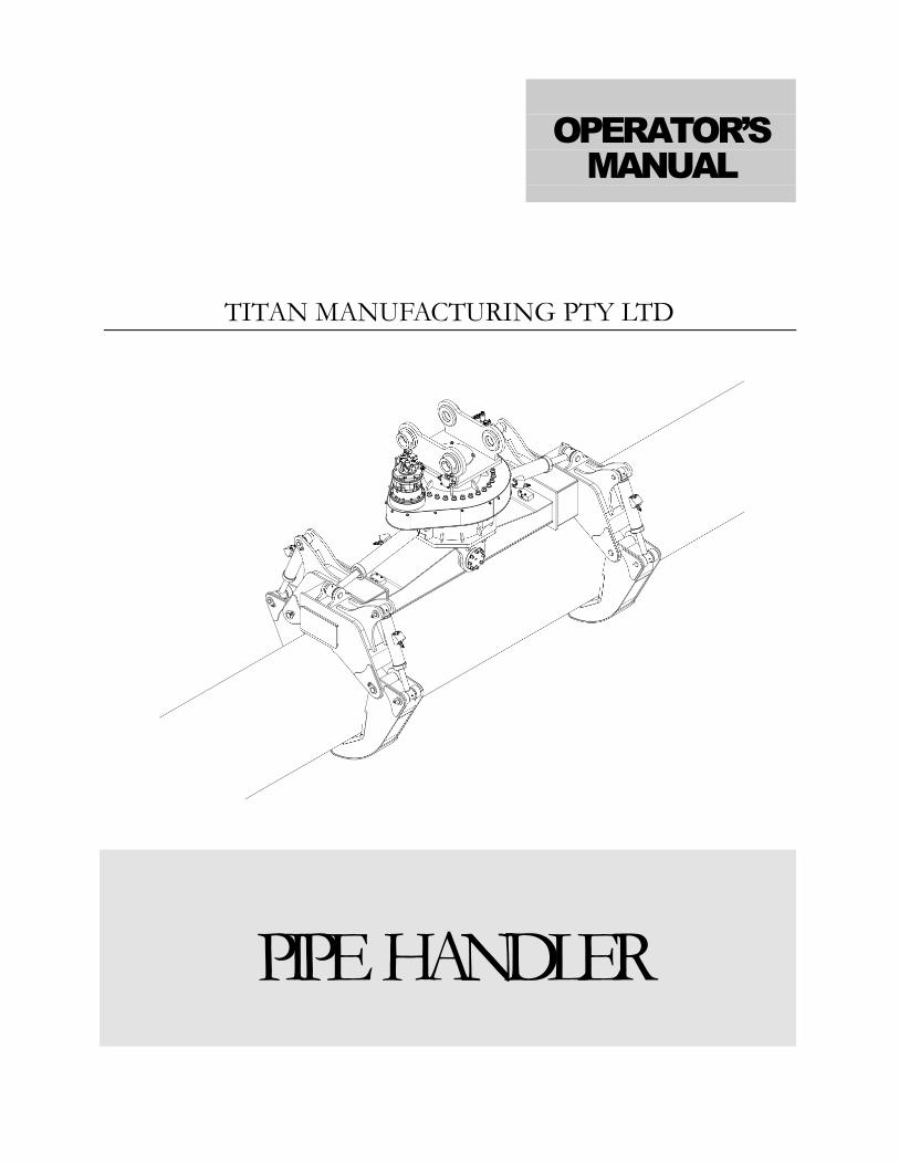
TITAN MANUFACTURING PTY LTD
PIPE HANDLER
OPERATOR’S
MANUAL

www.titanmanufacturing.com.au
TITAN Manufacturing Pty Ltd Level 1/55 Enterprise Street,
Cleveland, QLD 4163 Phone 07 3286 3794 • Fax 07 3286 4582
Table of Contents
Introduction .......................................................................................... ……1 Safety Precautions ...................................................................................... 3 Intended Use ................................................................................................. …5
Familiarization ............................................................................................. 6 Operation .................................................................................................... 9
Connecting to a quick coupler .......................................................................... 9
Picking-up and unloading of Pipes ................................................................. 10
Tilting of pipes ................................................................................................ 13
Rotating of pipes ............................................................................................. 14
Lifting capcity .................................................................................................. 14
Installation ................................................................................................ 15 Hydraulic Circuit ............................................................................................ 17
Electric Circuit ............................................................................................... 18
Maintenance ............................................................................................. 19
Preventive Maintenance ................................................................................. 20
Daily Inspections ............................................................................................ 21
Monthly Inspections ....................................................................................... 22
Annualy Inspections ...................................................................................... 22
Lubrication ..................................................................................................... 25
Spare Parts ............................................................................................... 28
Warranty ................................................................................................... 39
P I P E H A N D L E R
1
Introduction
ongratulations on purchasing your new Titan Pipe Handler. Please take the time to read this manual carefully to ensure you obtain optimum results from your new product.
To avoid injuries; read, understand and follow all safety precautions and procedures found in this manual before attempting operation, inspection or maintenance of this equipment. Manufacturer cannot anticipate every possible circumstance that might involve a potential hazard. The warnings in this publication and on the product are therefore not all inclusive. If a tool, procedure, work method or operation technique not specifically recommended by the manufacturer is used; you must satisfy yourself that it is safe for you and others. You should also ensure that the product will not be damaged or made unsafe by the operation, lubrication, maintenance and/or repair procedures you choose.
Chapter
1
C
P I P E H A N D L E R
2
GENERAL
This manual contains procedures to aid the operator gain peak performance through effective, economical operation and the maintenance of the equipment.
Before using the equipment, operators must thoroughly read and understand all Safety, Operation and Maintenance instructions found in this manual. Failure to follow the instructions given in this manual may lead to serious injury to persons or equipment failure.
Operators and persons working with this equipment should continually study this manual until proper Safety; Operation and Maintenance procedures are completely understood.
This manual describes the basic operating techniques. Skill is gained as the operator utilizes these techniques and perfects them with the actual equipment.
Some pictures may be different from your equipment, as technical improvement is continuous; manuals are periodically updated to reflect these changes.
This manual may not contain optional equipment. Please contact an authorized Manufacturer for any optional equipment required.
The contents of this manual and operation of the equipment are based on the use of genuine manufacturer sourced parts. Use of non-genuine replacement or modified parts is not recommended.
Materials and specifications are subject to change without notice.
NOTICE
Owing to the policy of continual improvement, changes may be made by the manufacturer to any of its products without any obligation on the part by the manufacturer.
P I P E H A N D L E R
3
Safety Precautions
Do not operate or perform any maintenance on this pipe handler until all instructions found in this manual have been thoroughly read and understood. Improper operation or maintenance of this equipment may cause accidents and could result in serious injury or death.
Always keep this manual with the pipe handler for further reference.
If manual is lost or damage, call manufacturer for replacement or log onto
www.titanmanufacturing.com.au to download another copy.
1. Most accidents, which occur during operation, are due to neglect of precautionary measures and
safety rules. Sufficient care should be taken to avoid these accidents. Lubrication and
maintenance services can be very dangerous and may cause injury. Therefore all precautionary
measures, DANGERS, WARNINGS, CAUTIONS and IMPORTANT contained in this
manual and on the pipe handler should be read and understood by all personnel before starting
any work with or on the pipe handler.
2. Operation, inspection, and maintenance should be carefully carried out, and safety must be
given the first priority. Safety messages are indicated using the following safety alert symbols
and signal words. The safety information contained in this manual is intended only to
supplement safety codes, insurance requirements, local laws, rules and regulations.
3. Messages of safety appear in this manual and are identified by the words “DANGER”,
“WARNING”, “CAUTION” and “IMPORTANT”.
4. While using this equipment, be sure to work with great care to avoid damage to the pipe
handler, and accidents from occurring.
Chapter
2
P I P E H A N D L E R
4
The serviceman or mechanic may be unfamiliar with many of the systems on this equipment. This makes it important to use caution when performing service work. Knowledge of the systems and components is important before removal or disassembly of any component. Because of the size of some components on this equipment, the serviceman or mechanic should use correct lifting procedures and if unsure of their capabilities of lifting, should consider a two person or assisted lift. The following is a list of basic precautions that must always be observed. 1. Read and understand this manual before operating, maintaining or repairing this equipment.
2. Always wear protective glasses and protective shoes whenever working on this equipment.
In particular, wear protective glasses when using hammers, punches or drifts on any part of
this equipment. Use safety gloves, hood/goggles, apron and the protective clothing
appropriate to the welding job being performed. Do not wear loose fitting or torn clothing.
Remove all rings from fingers, loose jewelry; confine long hair and loose clothing before
working on this equipment.
3. Do not work on any pipe handler that is only supported by the machine. Always place the
pipe handler on solid ground to reduce the risk of hydraulic failure of the machine.
4. Relieve all pressures in hydraulic lines before disconnecting. Always make sure raised
components are blocked correctly to ensure they cannot fall when lines are disconnected
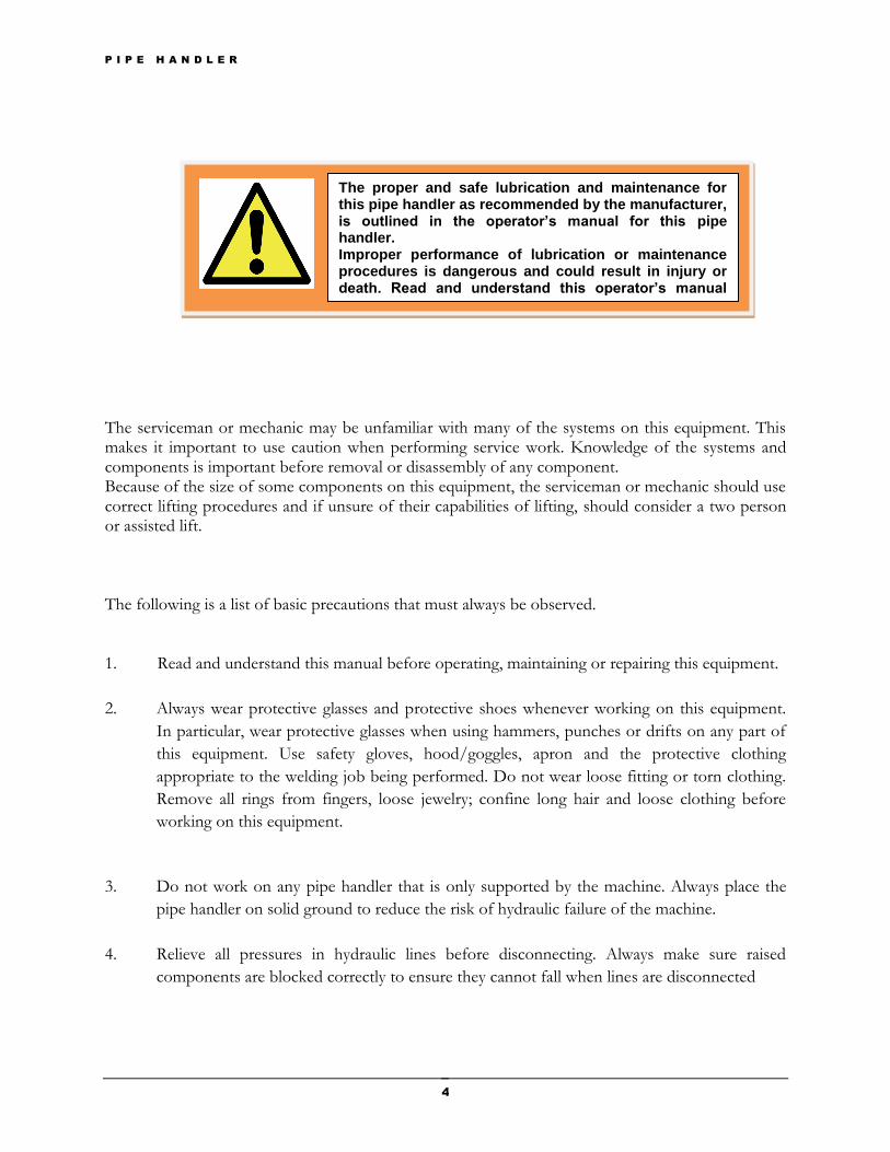
The proper and safe lubrication and maintenance for this pipe handler as recommended by the manufacturer, is outlined in the operator’s manual for this pipe handler. Improper performance of lubrication or maintenance procedures is dangerous and could result in injury or death. Read and understand this operator’s manual before performing any lubrication or maintenance.
P I P E H A N D L E R
5
5. Avoid back injury. Use a hoist when lifting components that weigh 20kg (45lb) or more.
Make sure all chains, hooks, slings, etc. are in good condition and are the correct rated
capacity to lift the weight you are lifting. Be sure hooks are positioned correctly. Lifting eyes
are not to be side loaded during a lifting operation.
6. Repairs which require welding should be performed only with the benefit of the appropriate
reference information and by personnel adequately trained and knowledgeable in welding
procedures. Determine the type of metal being welded and select correct welding procedure
to provide a weld metal strength at least equivalent of that of the parent metal.
Intended use
TITAN Pipe Handler is designed to use with all excavators. Hoist machine minimum requirements are given in the compliance plate attached to the pipe handler. The default pipe handler is included with UHMWPE wear pad. This is suitable for HDPE pipes or similar. The pipe handler is intended to use with following operations,
1. Picking-up and unloading of pipes
2. Moving of pipes for laying down
3. Positioning of pipes (rotating, and tilting)
4. Clamping of pipes for welding
P I P E H A N D L E R
6
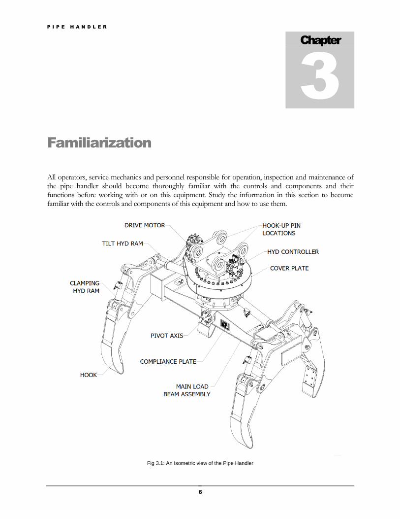
Familiarization
All operators, service mechanics and personnel responsible for operation, inspection and maintenance of the pipe handler should become thoroughly familiar with the controls and components and their functions before working with or on this equipment. Study the information in this section to become familiar with the controls and components of this equipment and how to use them.
Fig 3.1: An Isometric view of the Pipe Handler
Chapter
3
P I P E H A N D L E R
7
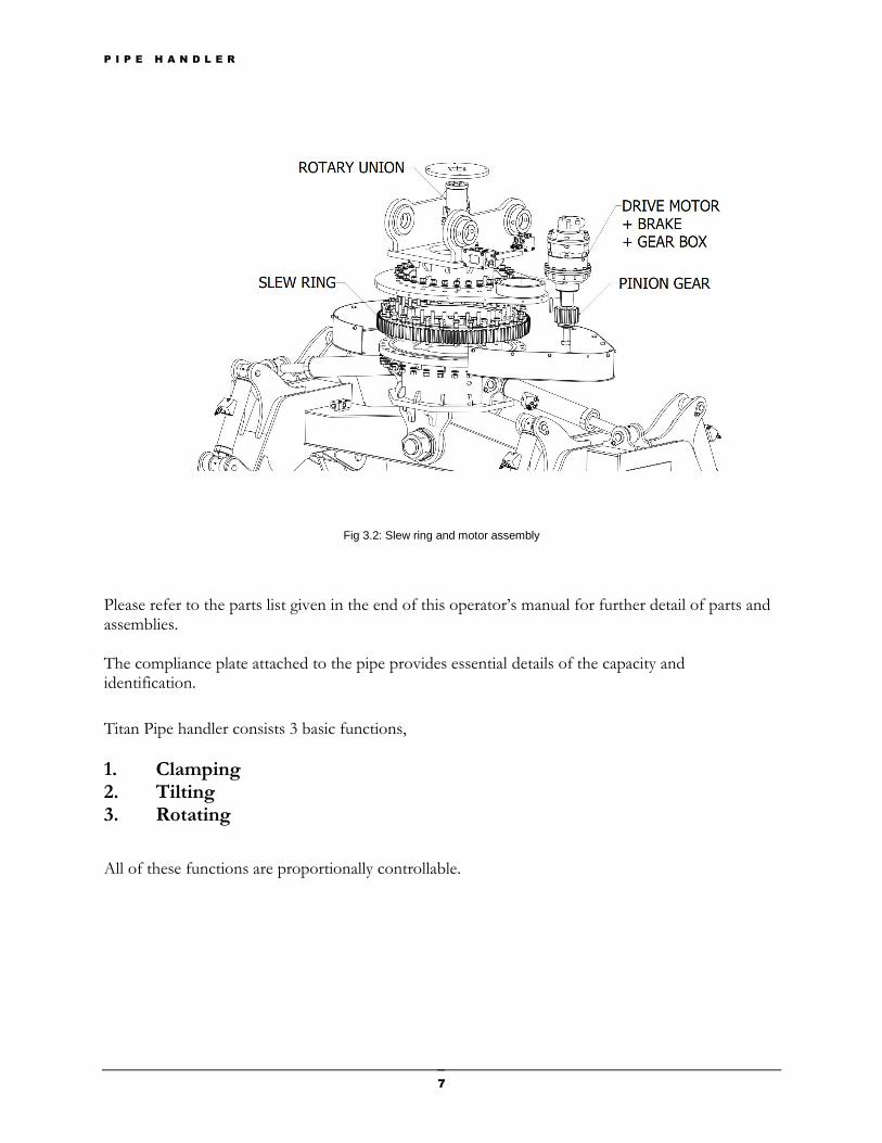
Fig 3.2: Slew ring and motor assembly
Please refer to the parts list given in the end of this operator’s manual for further detail of parts and assemblies. The compliance plate attached to the pipe provides essential details of the capacity and identification.
Titan Pipe handler consists 3 basic functions,
1. Clamping 2. Tilting 3. Rotating
All of these functions are proportionally controllable.
P I P E H A N D L E R
8
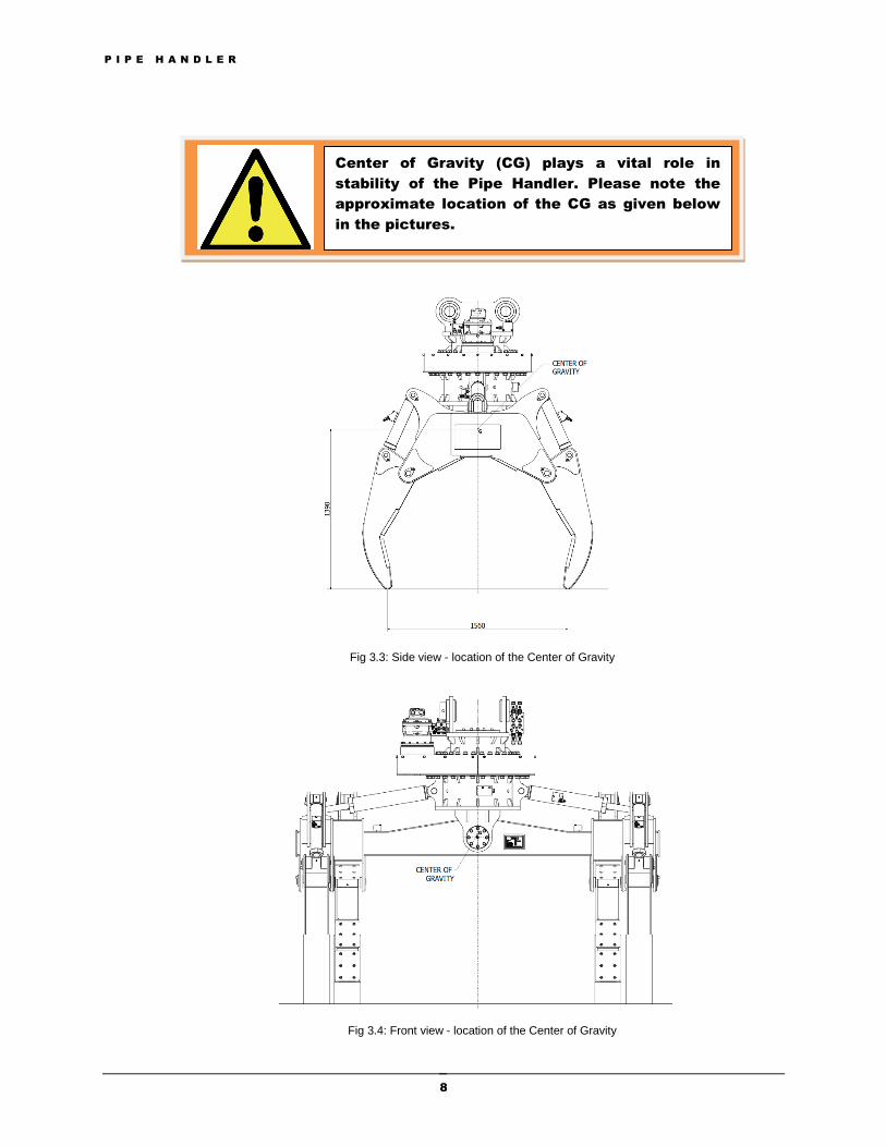
Fig 3.3: Side view - location of the Center of Gravity
Fig 3.4: Front view - location of the Center of Gravity
Center of Gravity (CG) plays a vital role in
stability of the Pipe Handler. Please note the
approximate location of the CG as given below
in the pictures.
P I P E H A N D L E R
9
Operation
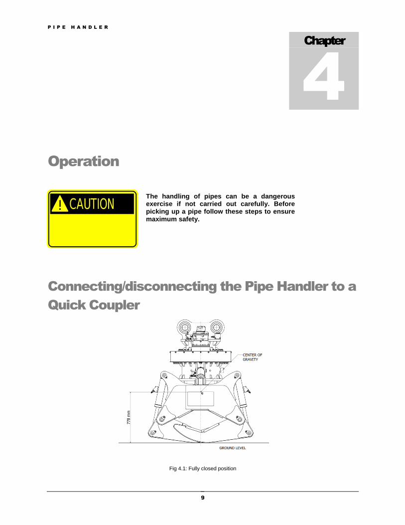
Connecting/disconnecting the Pipe Handler to a
Quick Coupler
Fig 4.1: Fully closed position
Chapter
4
The handling of pipes can be a dangerous exercise if not carried out carefully. Before picking up a pipe follow these steps to ensure maximum safety.
P I P E H A N D L E R
10
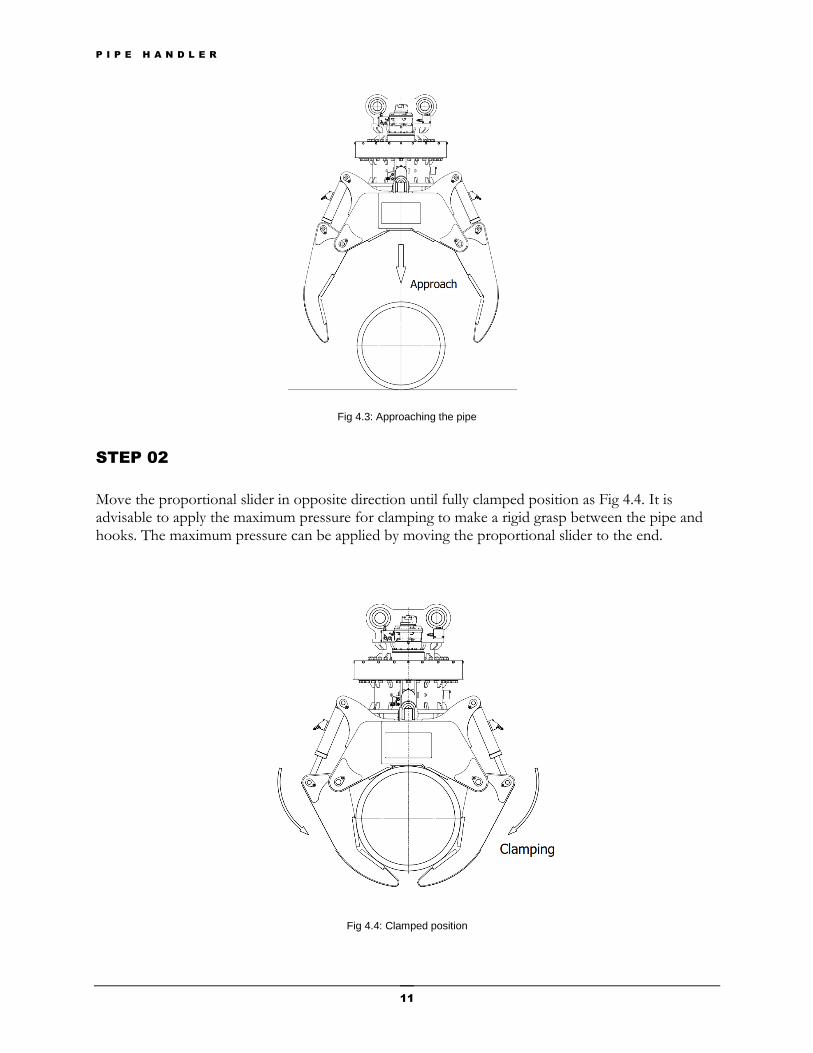
Fig 4.1 shows the fully closed position of the pipe handler. This position guarantees the lowest center of gravity (CG), resulting the most stable position on the ground level.
Picking-up and unloading of pipes
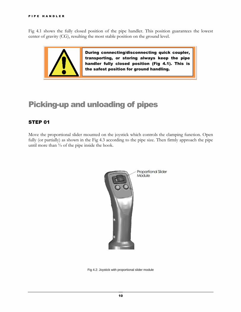
STEP 01
Move the proportional slider mounted on the joystick which controls the clamping function. Open fully (or partially) as shown in the Fig 4.3 according to the pipe size. Then firmly approach the pipe until more than ¾ of the pipe inside the hook.
Fig 4.2: Joystick with proportional slider module
During connecting/disconnecting quick coupler,
transporting, or storing always keep the pipe
handler fully closed position (Fig 4.1). This is
the safest position for ground handling.
P I P E H A N D L E R
11
Fig 4.3: Approaching the pipe
STEP 02
Move the proportional slider in opposite direction until fully clamped position as Fig 4.4. It is advisable to apply the maximum pressure for clamping to make a rigid grasp between the pipe and hooks. The maximum pressure can be applied by moving the proportional slider to the end.
Fig 4.4: Clamped position
P I P E H A N D L E R
12
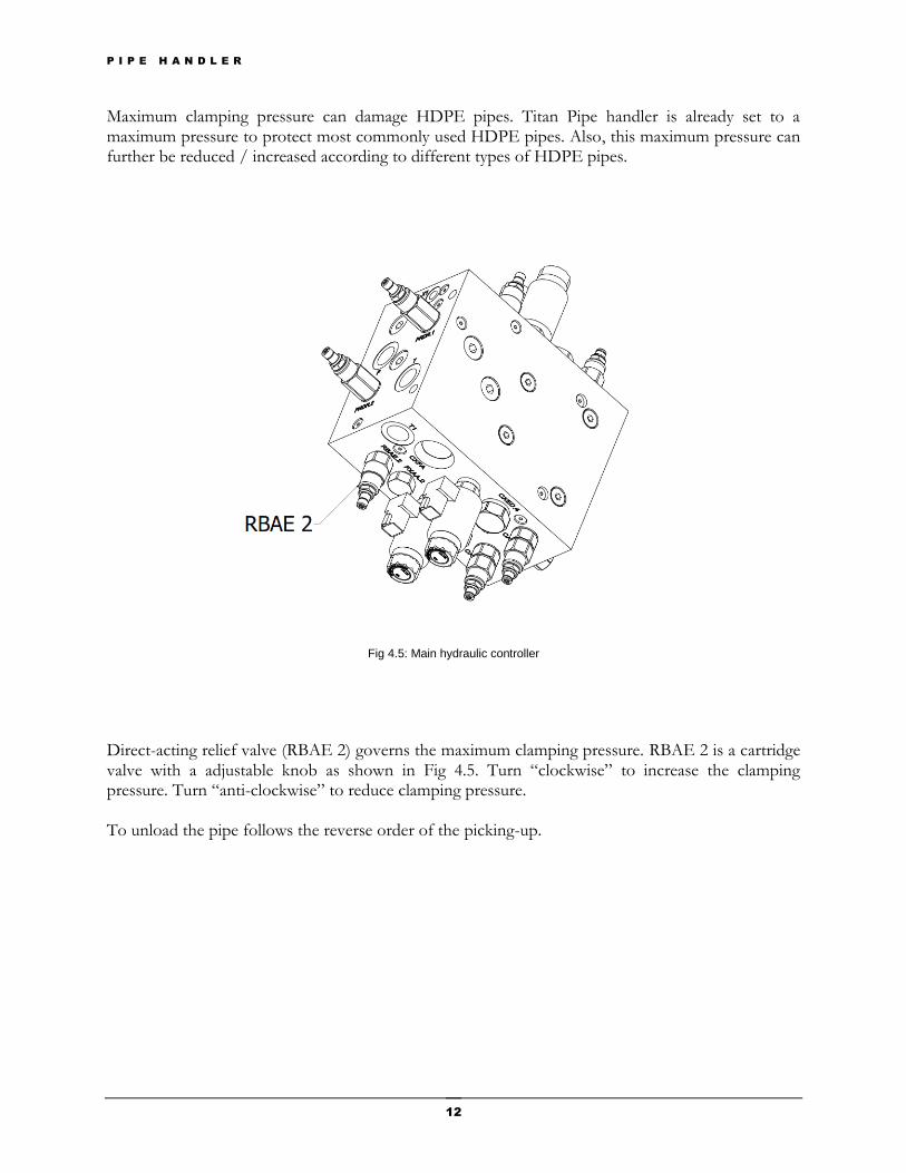
Maximum clamping pressure can damage HDPE pipes. Titan Pipe handler is already set to a maximum pressure to protect most commonly used HDPE pipes. Also, this maximum pressure can further be reduced / increased according to different types of HDPE pipes.
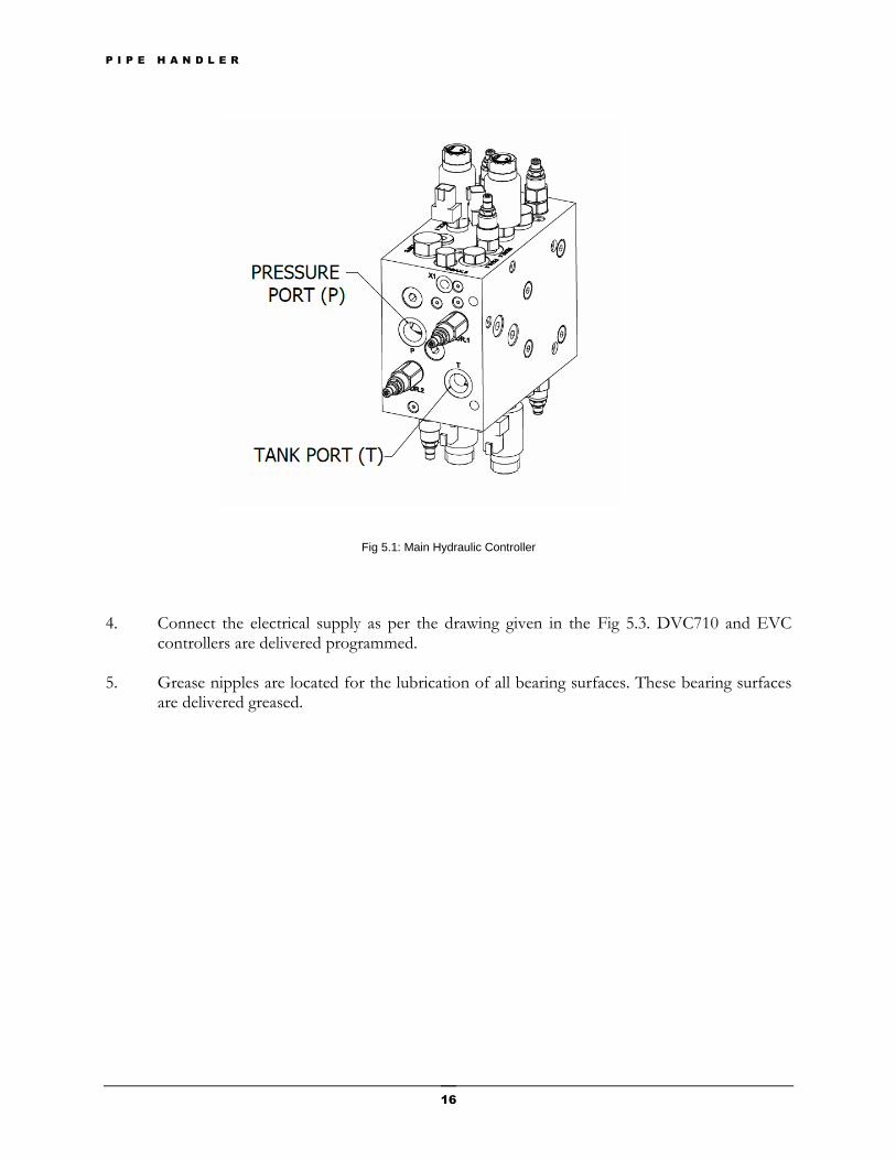
Fig 4.5: Main hydraulic controller
Direct-acting relief valve (RBAE 2) governs the maximum clamping pressure. RBAE 2 is a cartridge valve with a adjustable knob as shown in Fig 4.5. Turn “clockwise” to increase the clamping pressure. Turn “anti-clockwise” to reduce clamping pressure. To unload the pipe follows the reverse order of the picking-up.
P I P E H A N D L E R
13
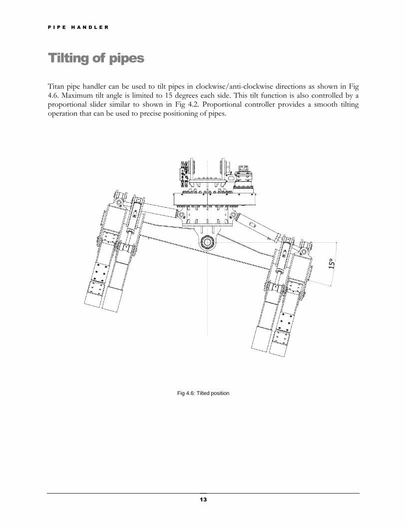
Tilting of pipes
Titan pipe handler can be used to tilt pipes in clockwise/anti-clockwise directions as shown in Fig 4.6. Maximum tilt angle is limited to 15 degrees each side. This tilt function is also controlled by a proportional slider similar to shown in Fig 4.2. Proportional controller provides a smooth tilting operation that can be used to precise positioning of pipes.
Fig 4.6: Tilted position
P I P E H A N D L E R
14
Rotating of pipes
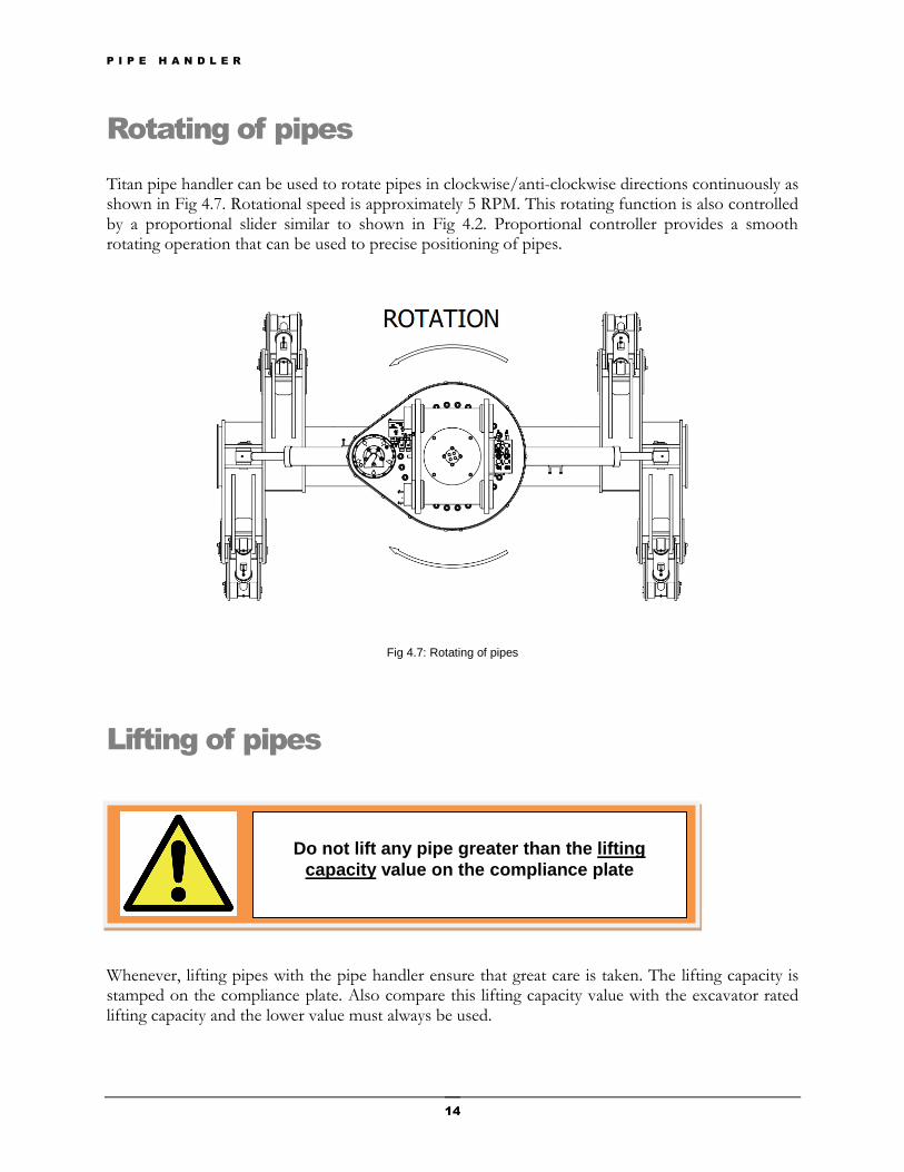
Titan pipe handler can be used to rotate pipes in clockwise/anti-clockwise directions continuously as shown in Fig 4.7. Rotational speed is approximately 5 RPM. This rotating function is also controlled by a proportional slider similar to shown in Fig 4.2. Proportional controller provides a smooth rotating operation that can be used to precise positioning of pipes.
Fig 4.7: Rotating of pipes
Lifting of pipes
Whenever, lifting pipes with the pipe handler ensure that great care is taken. The lifting capacity is stamped on the compliance plate. Also compare this lifting capacity value with the excavator rated lifting capacity and the lower value must always be used.
Do not lift any pipe greater than the lifting
capacity value on the compliance plate
P I P E H A N D L E R
15
Installation
1. Care should be taken when installing the pipe handler. Always use hardened, drilled and grooved pins in the top of the pipe handler. Hardened pins are NOT supplied with the pipe handler. When installing the hydraulic hoses and electrical wires to the pipe handler, they should be checked on full rotation around the pivot point of dipper arm for fretting or pinching of hoses or wires.
2. Please note that all hydraulic hoses and fittings connected into the pipe handler must be
thoroughly cleaned and flushed prior to installation to prevent damage to the hydraulic control system.
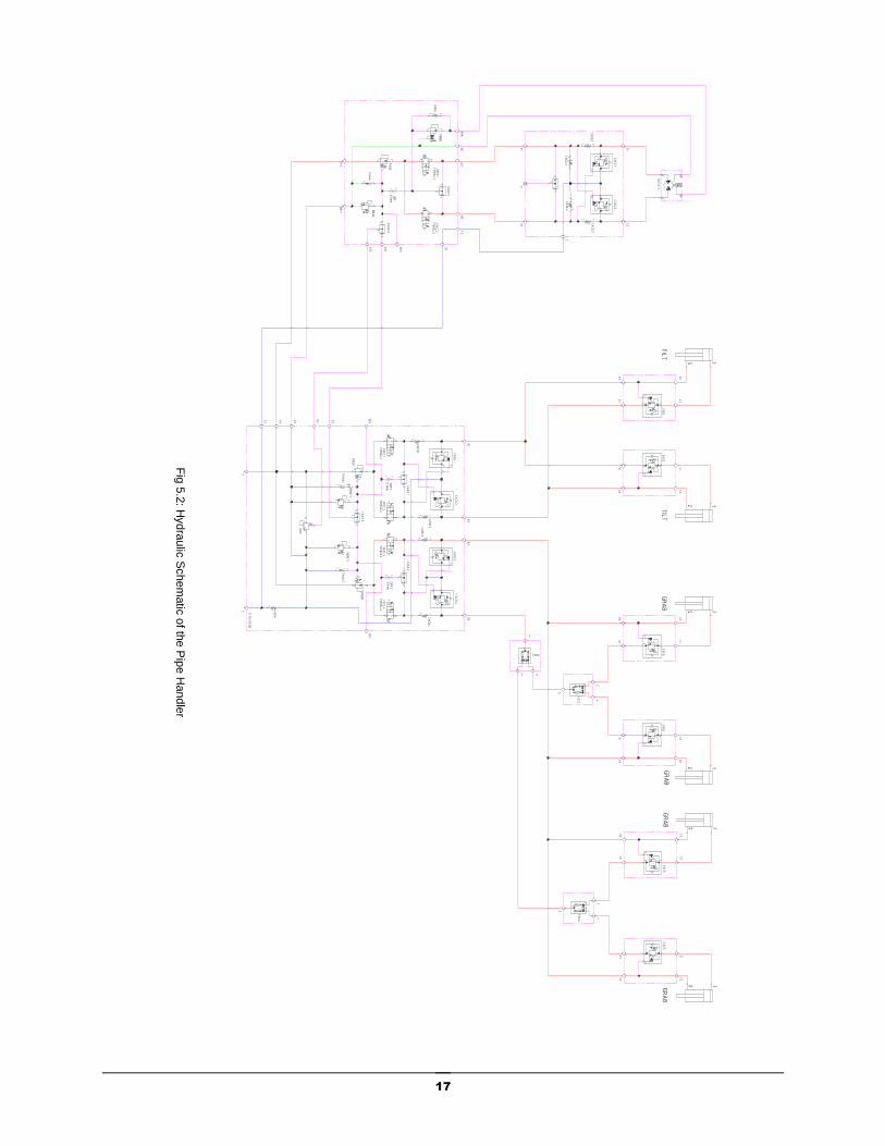
3. Connect the hydraulic supply as per the drawing given in the Fig 5.2. Hydraulic pressure
settings are given below in the table 5.1.
Table 5.1 Pressure settings for the controller
Maximum Pressure @ P
250 bar
Maximum Back Pressure @ T
5 bar
Flow Rate
100 LPM
Chapter
5
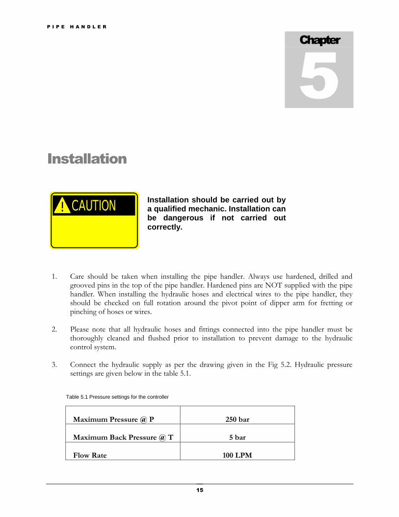
Installation should be carried out by a qualified mechanic. Installation can be dangerous if not carried out
correctly.
P I P E H A N D L E R
16
Fig 5.1: Main Hydraulic Controller
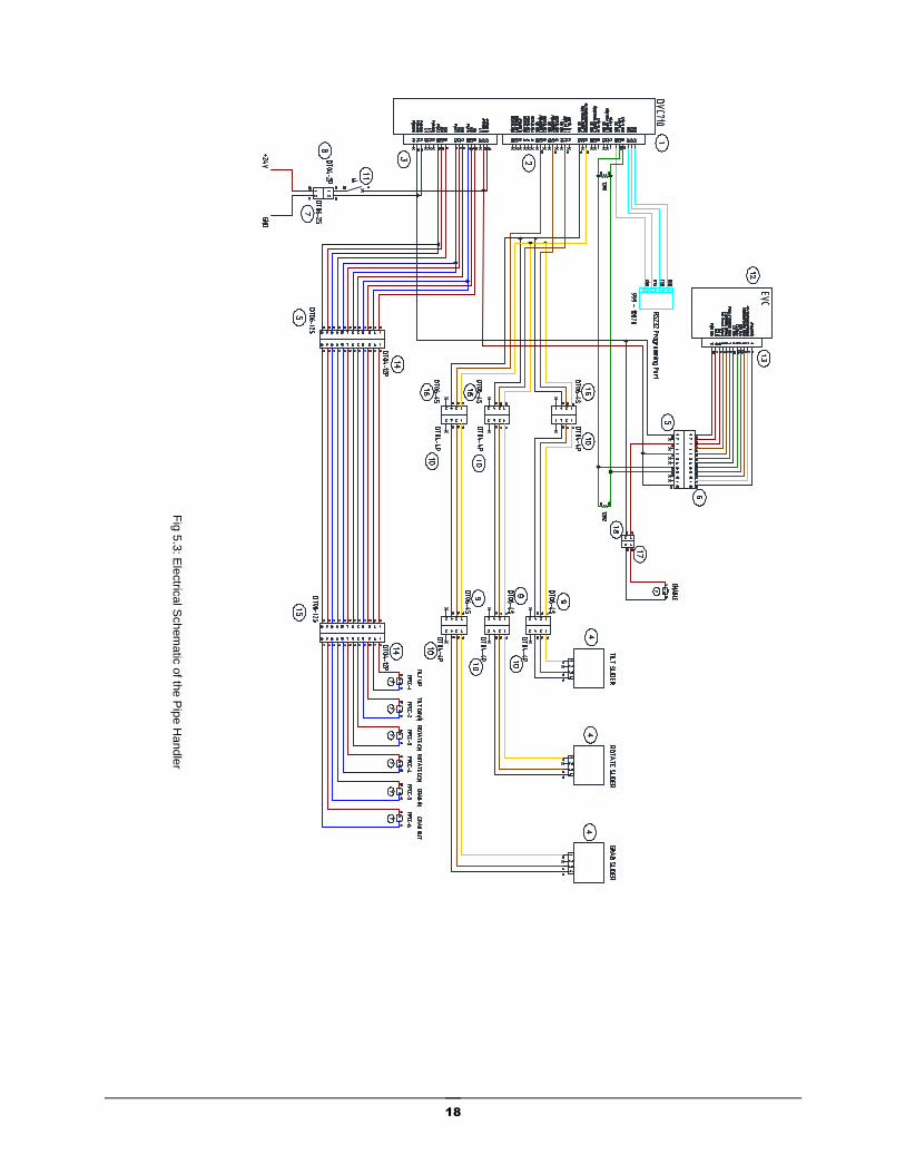
4. Connect the electrical supply as per the drawing given in the Fig 5.3. DVC710 and EVC controllers are delivered programmed.
5. Grease nipples are located for the lubrication of all bearing surfaces. These bearing surfaces
are delivered greased.
P I P E H A N D L E R
17
AB DR
BR
ROTATE
123
CACG.1
123
CACG.2
31
2
12
CXCD.1
12
CXCD.2
21
CXDA.1
21
CXDA.2
C1
C2
V1
V2
T
123
CACG
C1
C2
V1
V2
FSDS
2
3
4
FSCS
3
24
42
3
12
GRAB
CACG
C1
C2
V1
V2
GRAB
123
CACG
C1
C2
V1
V2
12
TILT
CACG
C1
C2
V1
V2
TILT
123
CACG
C1
C2
V1
V2
2
3
4
FSCS
3
24
12GRAB
CACG
C1
C2
V1
V2
GRAB
12 3
CACG.1
123
CACG.2
12 3
CACG.3
123
CACG.4
31
2 CSAX.1
31
2
CSAX.2
1 2
a
FPCC.1
770924.1
1 2
aFPCC.2
770924.2
1 2
a
FPCC.3
770924.3
1 2
aFPCC.4
770924.4
12
RBAE.1
12
RBAE.2
31
2
CSAX.3
12
3
LRFC
2 1
CXFA
12
ORF.1
0.5mm
12
ORF.2
0.5mm
A1
B1
A2
B2
PT
12
CXED.1
12
CXED.2
12CXED.3
12
CXED.4
TP1
TP2
2 1
FXAA.1
2 1
FXAA.2
P1
T1
Z1
X1
X2
S
31
2
CSAX.1
31
2 CSAX.2
2 1
FXAA
12
RBAE
1 2ORF
0.5mm
P11
DR11
A3
B3
X11
X22
TP3
3
12
PRDR
T3
T11
123
PBBB
2 1
CXBA
BRK
DR
1 2
a
FPCC.1
770924.1
1 2
a
FPCC.2
770924.2
3
12PRDR
bar
3
12
PRDR
Fig
5.2
: Hydra
ulic
Schem
atic
of th
e P
ipe H
andle
r
P I P E H A N D L E R
18
Fig
5.3
: Ele
ctric
al S
chem
atic
of th
e P
ipe H
andle
r
P I P E H A N D L E R
19
Maintenance
It is recommended that an inspection and maintenance schedule be developed and maintained with written records, on a regular basis to aid with any warranty claims. An example maintenance schedule is demonstrated below. Table 6.1: Maintenance record
DATE EXTENT OF WORK TECHNITIAN
Greased all points specified.
Checked for cracks and damages
Checked condition of hydraulic ram
Fastener survey
Chapter
6
Do not attempt other inspection or
maintenance procedures other than
those specified in the manual.
P I P E H A N D L E R
20
Preventive Maintenance
PROTECTION SURVEY A visual examination makes it possible to ensure the integrity of parts.
Absence of excessive stretch, cracks or tears
Signs of wear or damage
Correct positioning
Evidence of oil leakage
Check for pollutants such as sand, coal, metallic particles, etc.
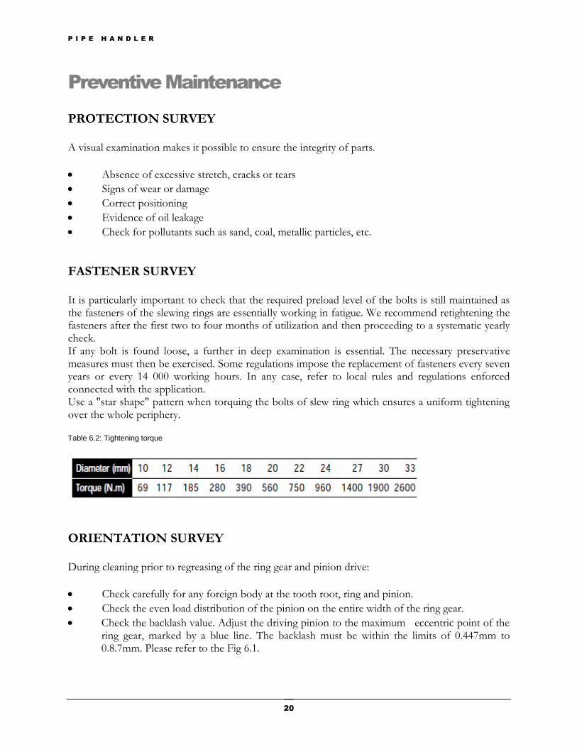
FASTENER SURVEY It is particularly important to check that the required preload level of the bolts is still maintained as the fasteners of the slewing rings are essentially working in fatigue. We recommend retightening the fasteners after the first two to four months of utilization and then proceeding to a systematic yearly check. If any bolt is found loose, a further in deep examination is essential. The necessary preservative measures must then be exercised. Some regulations impose the replacement of fasteners every seven years or every 14 000 working hours. In any case, refer to local rules and regulations enforced connected with the application. Use a "star shape" pattern when torquing the bolts of slew ring which ensures a uniform tightening over the whole periphery. Table 6.2: Tightening torque
ORIENTATION SURVEY During cleaning prior to regreasing of the ring gear and pinion drive:
Check carefully for any foreign body at the tooth root, ring and pinion.
Check the even load distribution of the pinion on the entire width of the ring gear.
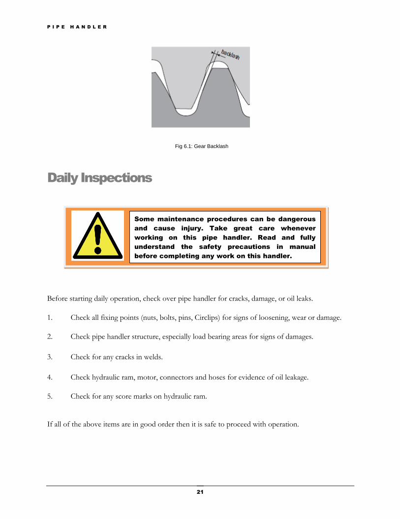
Check the backlash value. Adjust the driving pinion to the maximum eccentric point of the ring gear, marked by a blue line. The backlash must be within the limits of 0.447mm to 0.8.7mm. Please refer to the Fig 6.1.
P I P E H A N D L E R
21
Daily Inspections
Before starting daily operation, check over pipe handler for cracks, damage, or oil leaks.
1. Check all fixing points (nuts, bolts, pins, Circlips) for signs of loosening, wear or damage.
2. Check pipe handler structure, especially load bearing areas for signs of damages.
3. Check for any cracks in welds.
4. Check hydraulic ram, motor, connectors and hoses for evidence of oil leakage.
5. Check for any score marks on hydraulic ram.
If all of the above items are in good order then it is safe to proceed with operation.
Some maintenance procedures can be dangerous
and cause injury. Take great care whenever
working on this pipe handler. Read and fully
understand the safety precautions in manual
before completing any work on this handler.
Fig 6.1: Gear Backlash
P I P E H A N D L E R
22
Monthly Inspections
1. Thoroughly clean Pipe Handler.
2. Visually inspect the pipe handler structure, especially load bearing areas to ensure it is free
from defects and signs of excessive wear.
3. Check for any cracks in welds.
4. Check hydraulic ram, motor, connectors and hoses for evidence of oil leakage.
5. Check for any score marks on hydraulic ram.
6. Check condition of lifting hooks for evidence of fatigue, weld failure or stress.
7. Check condition of the all mechanical and electrical components.
If all of the above items are in good order then it is safe to proceed with operation.
Annually Inspections
1. Dissemble following items from the pipe handler.
Hooks
Hydraulic rams
Rotary union
2. Check hooks structure, especially load bearing areas for signs of damages.
3. Check for any cracks in welds.
4. Check hydraulic rotary union, ram, connectors and hoses for evidence of oil leakage.
5. It is recommended to carry out a pressure testing for the hydraulic rotary union and ram.
Maximum pressure (350bar, 5000PSI).
P I P E H A N D L E R
23
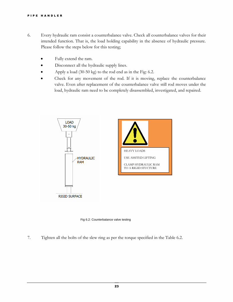
6. Every hydraulic ram consist a counterbalance valve. Check all counterbalance valves for their
intended function. That is, the load holding capability in the absence of hydraulic pressure.
Please follow the steps below for this testing;
Fully extend the ram.
Disconnect all the hydraulic supply lines.
Apply a load (30-50 kg) to the rod end as in the Fig: 6.2.
Check for any movement of the rod. If it is moving, replace the counterbalance
valve. Even after replacement of the counterbalance valve still rod moves under the
load, hydraulic ram need to be completely disassembled, investigated, and repaired.
7. Tighten all the bolts of the slew ring as per the torque specified in the Table 6.2.
HEAVY LOADS USE ASSITED LIFTING CLAMP HYDRAULIC RAM TO A RIGID STUCTURE
Fig 6.2: Counterbalance valve testing
P I P E H A N D L E R
24
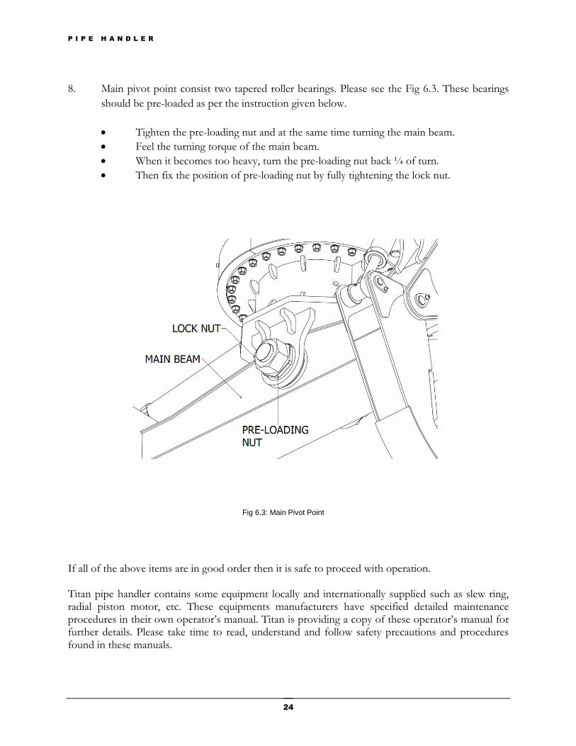
8. Main pivot point consist two tapered roller bearings. Please see the Fig 6.3. These bearings
should be pre-loaded as per the instruction given below.
Tighten the pre-loading nut and at the same time turning the main beam.
Feel the turning torque of the main beam.
When it becomes too heavy, turn the pre-loading nut back ¼ of turn.
Then fix the position of pre-loading nut by fully tightening the lock nut.
If all of the above items are in good order then it is safe to proceed with operation. Titan pipe handler contains some equipment locally and internationally supplied such as slew ring, radial piston motor, etc. These equipments manufacturers have specified detailed maintenance procedures in their own operator’s manual. Titan is providing a copy of these operator’s manual for further details. Please take time to read, understand and follow safety precautions and procedures found in these manuals.
Fig 6.3: Main Pivot Point
P I P E H A N D L E R
25
Lubrication
A suitable lubrication is essential for the longevity of the raceways of slew ring, gears, and bearings. The operating conditions such as loads, temperatures, speeds, vibrations, etc. determine the choice of lubricant. As being a significant component of the bearing, grease will improve the bearing capabilities and longevity.
Recommendations for bearing lubricants
Lithium-base soap.
Minimum viscosity of the base: 150 mm2/sec.
Grade NLGI 2.
Anti-wear and extreme pressure additives.
Service temperature : – 30° C à + 120° C
Greasing Frequency
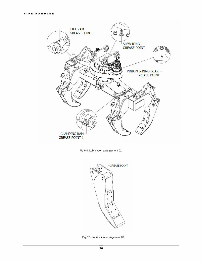
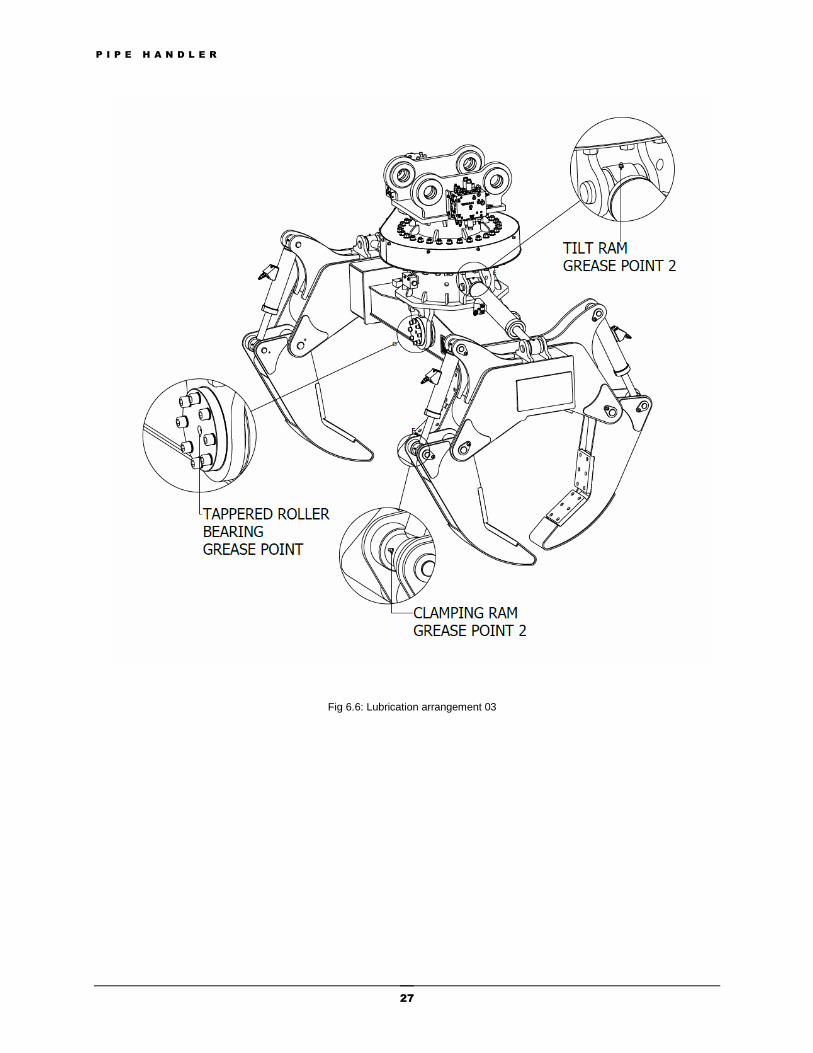
The greasing frequency varies according to utilization and environment. We recommend regreasing every 150 hours in normal usage. This frequency is to be reduced to 50 hours when the conditions of application are severe or if the environment is dusty or wet. Greasing is required, before and after a long idle period. Regrease every 6 months, while rotating, during prolonged idle periods. Apply grease to the points given in the Fig 6.4, Fig 6.5, and Fig 6.6 using a high pressure grease gun. All greasing points are located externally and easily accessible.
The proper and safe lubrication and maintenance for this pipe handler as recommended by the manufacturer, is outlined in the operator’s manual. Improper performance of lubrication or maintenance procedures is dangerous and could result in injury or death. Read and understand this operator’s manual before performing any lubrication or maintenance.
P I P E H A N D L E R
26
Fig 6.4: Lubrication arrangement 01
Fig 6.5: Lubrication arrangement 02
P I P E H A N D L E R
27
Fig 6.6: Lubrication arrangement 03
P I P E H A N D L E R
28
Spare Parts
The spare parts list includes illustrations of the assemblies which make up the pipe handler. All spare parts are identified by a unique part number. When ordering parts, your order should specify the part number, quantity, and part name. Continuing improvement of product design may cause changes to the product which may not be included in this publication. Each publication is revised to update and include these changes in later editions. TITAN reserves the right to alter part number and forms of consisting parts for improvement without prior notice. Whenever a question arises regarding your product or this parts list, please consult TITAN for latest information. For satisfactory service, we recommend the use of genuine TITAN parts.
Chapter
7
P I P E H A N D L E R
29
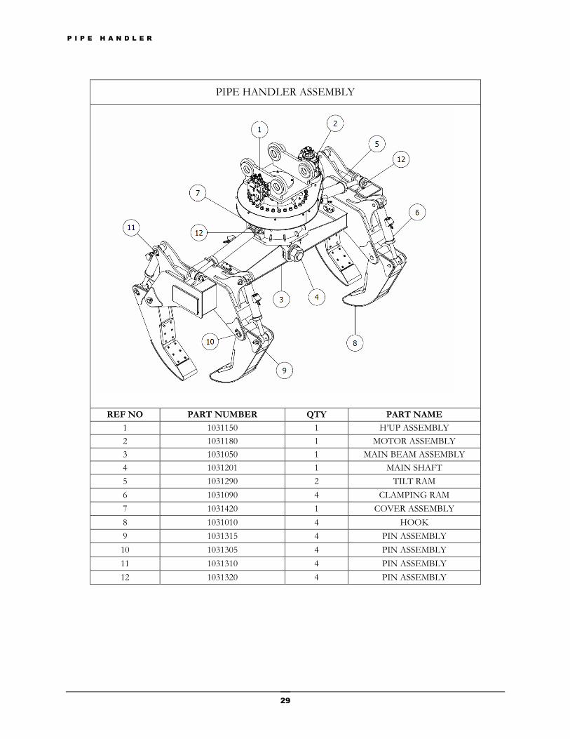
PIPE HANDLER ASSEMBLY
REF NO PART NUMBER QTY PART NAME
1 1031150 1 H’UP ASSEMBLY
2 1031180 1 MOTOR ASSEMBLY
3 1031050 1 MAIN BEAM ASSEMBLY
4 1031201 1 MAIN SHAFT
5 1031290 2 TILT RAM
6 1031090 4 CLAMPING RAM
7 1031420 1 COVER ASSEMBLY
8 1031010 4 HOOK
9 1031315 4 PIN ASSEMBLY
10 1031305 4 PIN ASSEMBLY
11 1031310 4 PIN ASSEMBLY
12 1031320 4 PIN ASSEMBLY
P I P E H A N D L E R
30
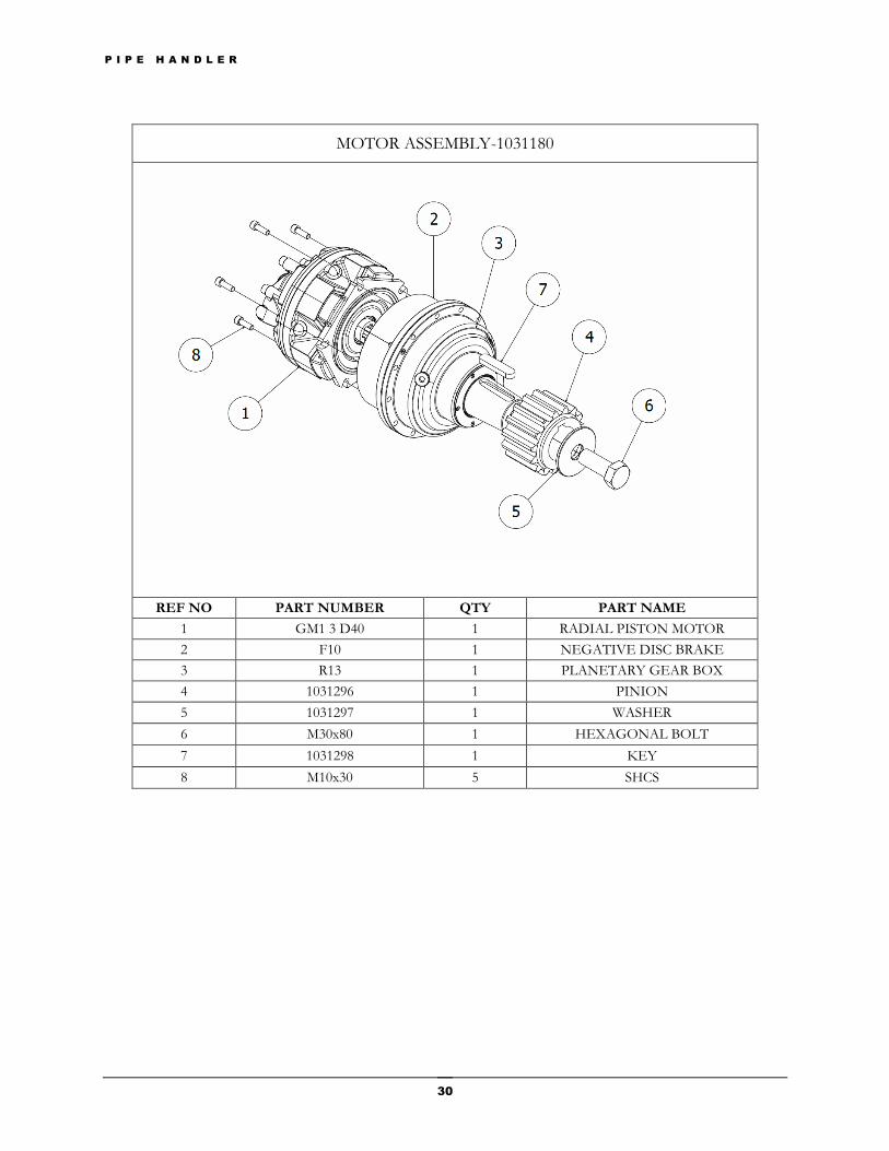
MOTOR ASSEMBLY-1031180
REF NO PART NUMBER QTY PART NAME
1 GM1 3 D40 1 RADIAL PISTON MOTOR
2 F10 1 NEGATIVE DISC BRAKE
3 R13 1 PLANETARY GEAR BOX
4 1031296 1 PINION
5 1031297 1 WASHER
6 M30x80 1 HEXAGONAL BOLT
7 1031298 1 KEY
8 M10x30 5 SHCS
P I P E H A N D L E R
31
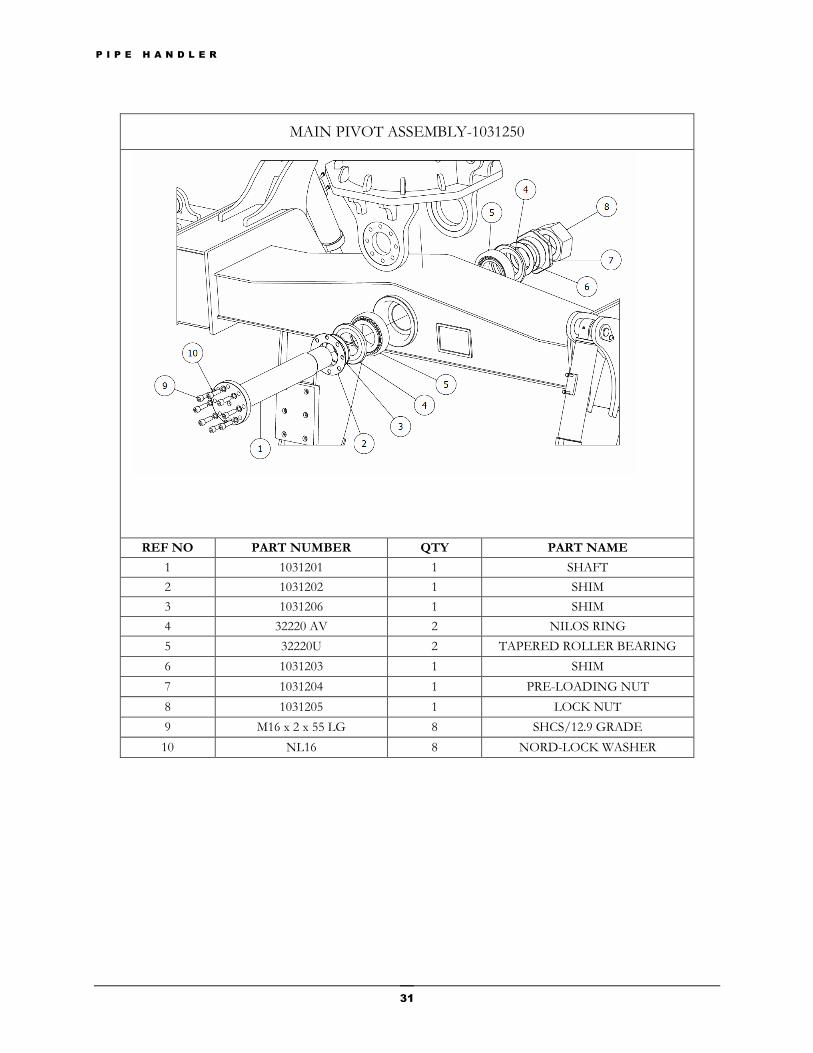
MAIN PIVOT ASSEMBLY-1031250
REF NO PART NUMBER QTY PART NAME
1 1031201 1 SHAFT
2 1031202 1 SHIM
3 1031206 1 SHIM
4 32220 AV 2 NILOS RING
5 32220U 2 TAPERED ROLLER BEARING
6 1031203 1 SHIM
7 1031204 1 PRE-LOADING NUT
8 1031205 1 LOCK NUT
9 M16 x 2 x 55 LG 8 SHCS/12.9 GRADE
10 NL16 8 NORD-LOCK WASHER
P I P E H A N D L E R
32
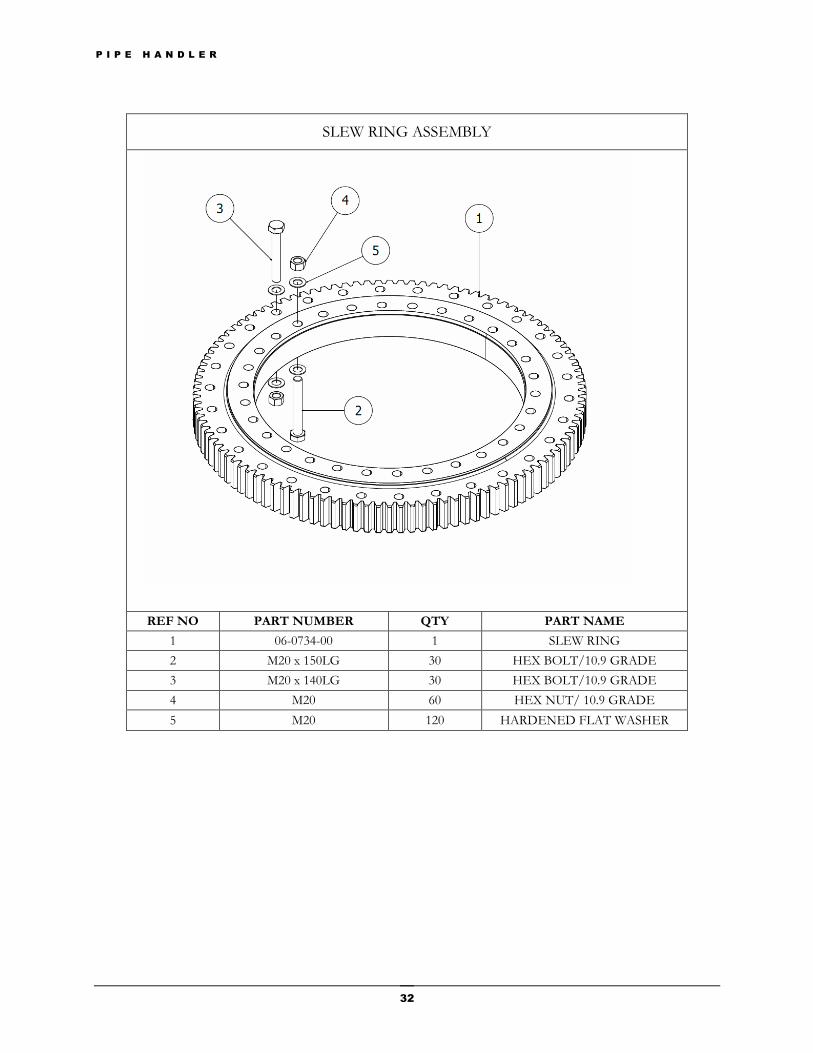
SLEW RING ASSEMBLY
REF NO PART NUMBER QTY PART NAME
1 06-0734-00 1 SLEW RING
2 M20 x 150LG 30 HEX BOLT/10.9 GRADE
3 M20 x 140LG 30 HEX BOLT/10.9 GRADE
4 M20 60 HEX NUT/ 10.9 GRADE
5 M20 120 HARDENED FLAT WASHER
P I P E H A N D L E R
33
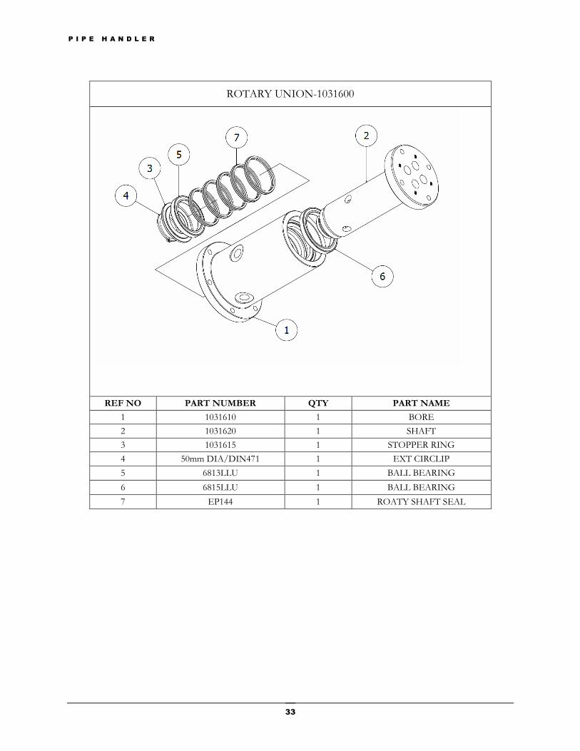
ROTARY UNION-1031600
REF NO PART NUMBER QTY PART NAME
1 1031610 1 BORE
2 1031620 1 SHAFT
3 1031615 1 STOPPER RING
4 50mm DIA/DIN471 1 EXT CIRCLIP
5 6813LLU 1 BALL BEARING
6 6815LLU 1 BALL BEARING
7 EP144 1 ROATY SHAFT SEAL
P I P E H A N D L E R
34
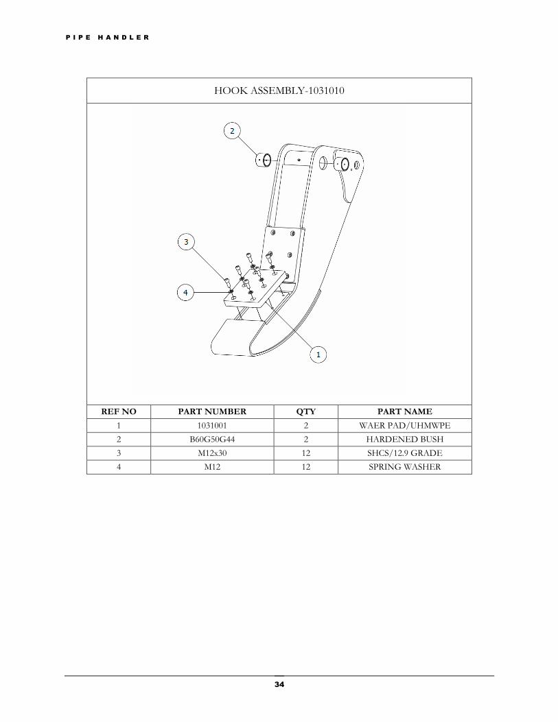
HOOK ASSEMBLY-1031010
REF NO PART NUMBER QTY PART NAME
1 1031001 2 WAER PAD/UHMWPE
2 B60G50G44 2 HARDENED BUSH
3 M12x30 12 SHCS/12.9 GRADE
4 M12 12 SPRING WASHER
P I P E H A N D L E R
35
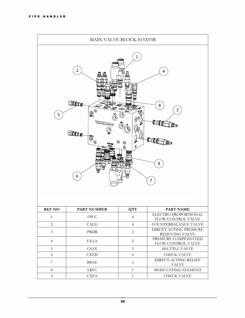
MAIN VALVE BLOCK-S15X93B
REF NO PART NUMBER QTY PART NAME
1 FPCC 4 ELECTRO-PROPORTIONAL
FLOW CONTROL VALVE
2 CACG 4 COUNTERBALANCE VALVE
3 PRDR 2 DIRCET-ACTING PRESSURE
REDUCING VALVE
4 FXAA 2 PRESSURE COMPENSATED
FLOW CONTROL VALVE
5 CSAX 3 SHUTTLE VALVE
6 CXED 4 CHECK VALVE
7 RBAE 2 DIRECT-ACTING RELIEF
VALVE
8 LRFC 1 MODULATING ELEMENT
9 CXFA 1 CHECK VALVE
P I P E H A N D L E R
36
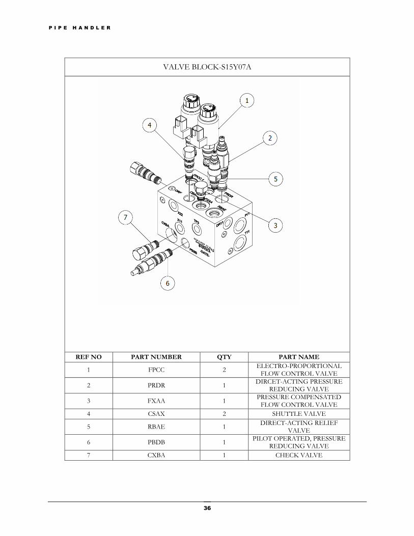
VALVE BLOCK-S15Y07A
REF NO PART NUMBER QTY PART NAME
1 FPCC 2 ELECTRO-PROPORTIONAL
FLOW CONTROL VALVE
2 PRDR 1 DIRCET-ACTING PRESSURE
REDUCING VALVE
3 FXAA 1 PRESSURE COMPENSATED
FLOW CONTROL VALVE
4 CSAX 2 SHUTTLE VALVE
5 RBAE 1 DIRECT-ACTING RELIEF
VALVE
6 PBDB 1 PILOT OPERATED, PRESSURE
REDUCING VALVE
7 CXBA 1 CHECK VALVE
P I P E H A N D L E R
37
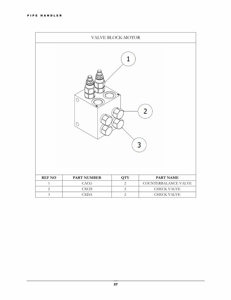
VALVE BLOCK-MOTOR
REF NO PART NUMBER QTY PART NAME
1 CACG 2 COUNTERBALANCE VALVE
2 CXCD 2 CHECK VALVE
3 CXDA 2 CHECK VALVE
P I P E H A N D L E R
38
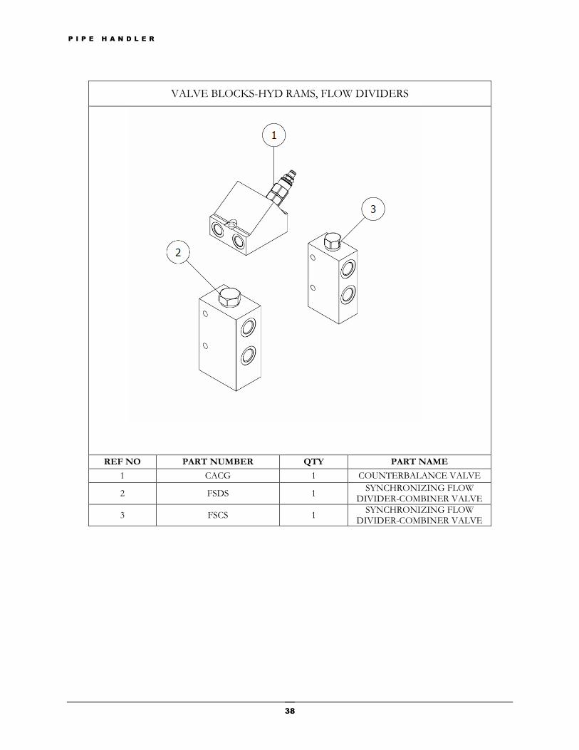
VALVE BLOCKS-HYD RAMS, FLOW DIVIDERS
REF NO PART NUMBER QTY PART NAME
1 CACG 1 COUNTERBALANCE VALVE
2 FSDS 1 SYNCHRONIZING FLOW
DIVIDER-COMBINER VALVE
3 FSCS 1 SYNCHRONIZING FLOW
DIVIDER-COMBINER VALVE
P I P E H A N D L E R
39
Warranty
1. LIMITED WARRANTY. If you follow all instructions and use the equipment in the appropriate manner, the equipment will perform substantially.
2. TERM OF WARRANTY. Goods are hereby sold and warranted against any defect in
workmanship appearing under proper usage within six (6) months from date of delivery. 3. EXCLUSIONS FROM WARRANTY. This warranty does not cover problems caused by
your acts (or failures to act), the acts of others, or events beyond the reasonable control of the manufacturer or installer. The manufacturer reserves the right to make null and void the warranty should the equipment be modified, altered, damaged or put to any undue stress other than in the way the equipment was designed to perform (including but not limited to the Customer’s failure to engage the safety pin during quick coupler operation).
4. WORK AND/OR SERVICE CARRIED OUT ON EQUIPMENT BY ANYONE
OTHER THAN MANUFACTURER. Any work and/or service carried out on the equipment by anyone other than Titan Manufacturing shall make the warranty null and void unless the Customer obtains prior written consent before any remedial work is carried out.
5. WARRANTY PROCEDURES. In respect of all claims the supplier shall not be liable to
compensate the Customer for any delay in either replacing or repairing the equipment or in properly assessing the Customers claims.
6. NO OTHER WARRANTIES. The limited warranty is the only direct warranty from the
manufacturer (Titan Manufacturing). No express warranty is given as to fitness or suitability of the equipment for any specific application or use unless expressly endorsed by the supplier.
7. RETURN OR GOODS. Return of equipment from the Customer to the
supplier/manufacturer can only be made with the prior written approval of the Supplier.
Chapter
7
P I P E H A N D L E R
40
8. DESIGN UPDATES. The manufacturer reserves the right to make changes and improvements to its Goods and Equipment without incurring any obligations whatsoever to install or make any changes and improvements to Goods and/or Equipment already supplied.
9. TRAINING ON USE OF EQUIPMENT. The Customer shall insure that its operator is
licensed to operate the Equipment which the Supplier’s Goods and/or Equipment form part thereof and is trained in the correct use of the Goods and/or Equipment.
10. The Warranty does not extend to components or accessory equipment which is not
manufactured by the Supplier. The Supplier agrees to assign to the Customer on request any manufacturer’s warranty under contract or by implication or operation of law to the extent possible.
11. The Supplier warrants that the Work will be carried out in accordance with all
relevant laws in an appropriate and skilful way, in accordance with the plans and specifications supplied by the Customer using materials that are good and suitable for the purpose for which they are intended to be used.
12. The Customer shall inspect the Goods on delivery and shall within seven (7) days of
delivery notify the Supplier of any alleged shortage in quantity, damage or failure to comply
with the description. The Customer shall afford the Supplier an opportunity to inspect the
Goods within a reasonable time following delivery if the Customer believes the Goods are
defective in any way. If the Customer shall fail to comply with these provisions the Goods
shall be conclusively presumed to be in accordance with the terms and conditions and free
from any damage.
13. All labour costs in replacing defective parts and all costs of transportation of such parts are
the responsibility of the Customer. 14. The Customer agrees that it will not make any claim against the Supplier and further
indemnifies the Supplier against all loss or damage to person or property that may be occasioned due to the Customer’s failure to carry out operator training in the correct use of the Goods. For the avoidance of doubt this includes any and all loss or damage due to negligence on the part of the Customer, its officers, employees or agents.