Embed Size (px)
Citation preview

Operator's Manualand
Parts Book
1000Accumulator
Effective: Nov 2013Revision "E"
Serial No.: 05316-Current
Printed in USA Part No: 02352
HOELSCHER, INC.312 S Main Bushton, KS 67427
Phone: 620-562-3575 Fax: 620-562-3359www.hoelscherinc.com
Each operator should read and understand thecontents of this manual before using the machine.
COMMERCIAL PRODUCTS
!READ
BEFORE USE


IntroductonThe purpose of this manual, is to explain the safe operation and maintenance of the Model 1000 Bale Ac-cumulator. Everyone who will be using the machine should first acquaint themselves with the safety and operational procedures explained in this manual. Your dealer will review the safety precautions, operation, maintenance and adjustment procedures with you at the time of delivery. He willl assist in filling out the Warranty Registration, which should be returned to us within 10 days of you taking receipt of the equip-ment.
ContentsGeneral Warranty.................................................1 Specifications.........................................1 Machine Identification............................1Safety Safety Words.........................................2 Equipment Safety Guidelines................3 Lighting and Marking.............................3 Safety Sign Care...................................3 Tire Safety..............................................3 Before Operation...................................4 During Operation...................................4 Following Operation...............................4 Highway and Transport Operations.......5 Performing Maintenance.......................5 Safety Sign Locations............................6Set-up and Pre-operation Installation and Pre-operation...........7, 8 Set-up Instructions.................................9 Caster Brake Assembly & Adjustment.10 Attaching to Conventional Baler...........11 Attaching to Center-line Baler..............12 Bale Length Adjustment.......................13 Control Lever and Detent Adjustment.14 Hydraulic System Conversion.............15 Use of Actuating Screw.......................16 Side Rail and Control Bar Adjustment.17 Safety Valve Adjustment & Cleaning...18 Lubrication...........................................19 Arm Speed Control..............................20Operation Operation.......................................21, 22Troubleshooting Troubleshooting.............................23, 24Options Wagon Hitch........................................25 15 Bale Conversion.............................26 Side Hill Kit..........................................27 Hold-down Kit......................................28 Bed Extension Kit................................29 Hydraulic Power Pack.........................30 Dolly Wheel.........................................31Parts Frame Assembly..................................32 Push-over Arm Assembly.....................33 Bed Assembly......................................34 Hydraulic Assembly..............................35 Hydraulic Control Assembly.................36Appendix Bolt Torque..........................................37 Tire Inflation.........................................37 Tire Warranty Information....................37
Identification Plate
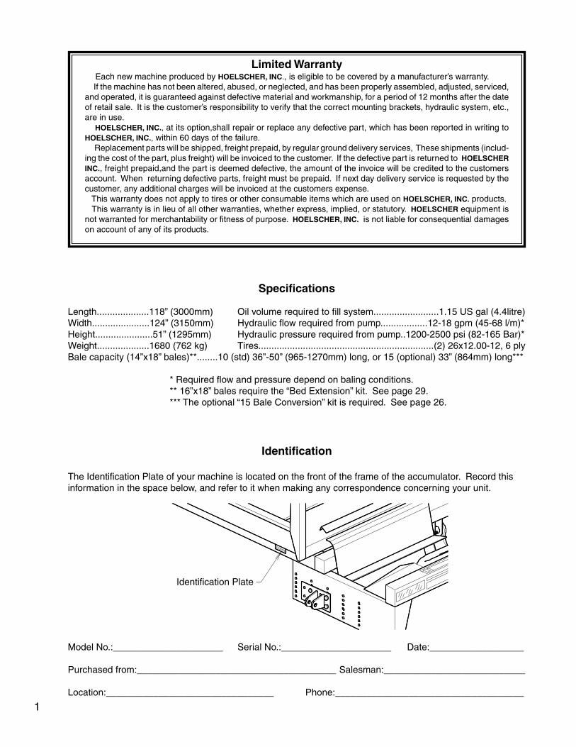
Limited Warranty Each new machine produced by HOELSCHER, INC., is eligible to be covered by a manufacturer’s warranty. If the machine has not been altered, abused, or neglected, and has been properly assembled, adjusted, serviced, and operated, it is guaranteed against defective material and workmanship, for a period of 12 months after the date of retail sale. It is the customer’s responsibility to verify that the correct mounting brackets, hydraulic system, etc., are in use. HOELSCHER, INC., at its option,shall repair or replace any defective part, which has been reported in writing to HOELSCHER, INC., within 60 days of the failure. Replacement parts will be shipped, freight prepaid, by regular ground delivery services, These shipments (includ-ing the cost of the part, plus freight) will be invoiced to the customer. If the defective part is returned to HOELSCHER INC., freight prepaid,and the part is deemed defective, the amount of the invoice will be credited to the customers account. When returning defective parts, freight must be prepaid. If next day delivery service is requested by the customer, any additional charges will be invoiced at the customers expense. This warranty does not apply to tires or other consumable items which are used on HOELSCHER, INC. products. This warranty is in lieu of all other warranties, whether express, implied, or statutory. HOELSCHER equipment is not warranted for merchantability or fitness of purpose. HOELSCHER, INC. is not liable for consequential damages on account of any of its products.
Specifications
Length....................118” (3000mm) Oil volume required to fill system.........................1.15 US gal (4.4litre)Width......................124” (3150mm) Hydraulic flow required from pump..................12-18 gpm (45-68 l/m)*Height......................51” (1295mm) Hydraulic pressure required from pump..1200-2500 psi (82-165 Bar)*Weight....................1680 (762 kg) Tires...................................................................(2) 26x12.00-12, 6 plyBale capacity (14”x18” bales)**........10 (std) 36”-50” (965-1270mm) long, or 15 (optional) 33” (864mm) long***
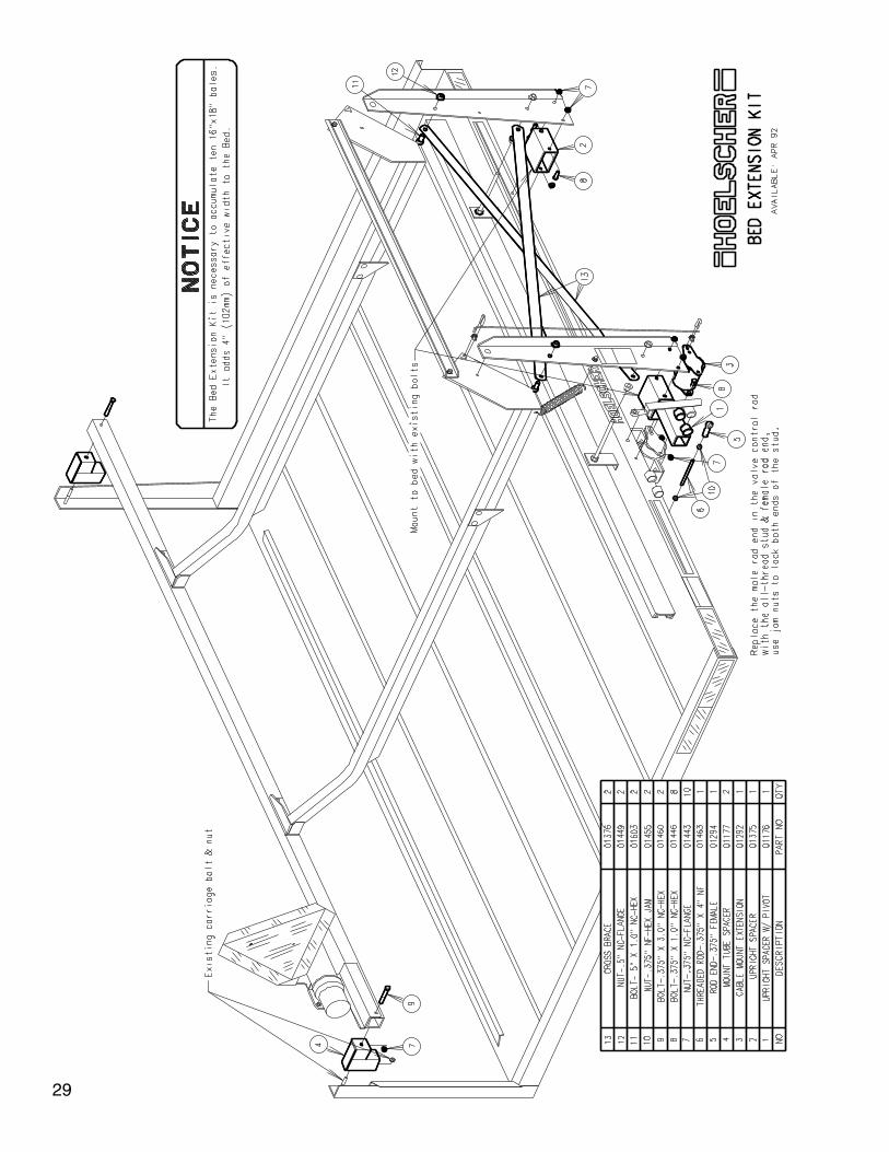
* Required flow and pressure depend on baling conditions. ** 16”x18” bales require the “Bed Extension” kit. See page 29. *** The optional “15 Bale Conversion” kit is required. See page 26.
Identification
The Identification Plate of your machine is located on the front of the frame of the accumulator. Record this information in the space below, and refer to it when making any correspondence concerning your unit.
Model No.:_____________________ Serial No.:_____________________ Date:__________________
Purchased from:______________________________________ Salesman:___________________________
Location:________________________________ Phone:____________________________________
1

This symbol means:
-YOUR SAFETY IS INVOLVED!
-BECOME ALERT!
-ATTENTION!
DANGER, indicates an imminently hazardous situation that, if not avoided, will result in death or serious injury. This signal word is to be limited to the most extreme situ-ations typically for machine components which, for functional purposes, cannot be guarded.
Signal WordsNote the use of the signal words DANGER, WARNING, and CAUTION with the safety messages. The appropri-ate signal word for each has been selected using the following guidelines.
WARNING, indicates a potentially hazardous situation that, if not avoided, could result in death or serious injury, and includes hazards that are exposed when guards are removed. It may also be used to alert against unsafe practices.
CAUTION, indicates a potentially hazardous situation that, if not avoided, may result in minor or moderate injury. It may also be used to alert against unsafe practices.
Safety Symbol Take note! This SAFETY ALERT SYMBOL found throughout this manual, and on safety signs, is used to call your attention to instructions involving your personal safety and the safety of others. Failure to follow these instructions can result in injury or death.
If you have questions not answered in this manual, or require additional copies, contact:HOELSCHER INC - 312 S Main St - Bushton, KS 67427
620-562-3575 - www.hoelscherinc.com
2

SAFETY...YOU CAN LIVE WITH IT
Equipment Safety Guidelines
Safety of the operator is one of our main concerns, and we have built in as many safety features as possible. However, accidents occur which could have been avoided by the operator’s careful approach to handling equipment. You, the operator, can avoid many accidents by observing the following precautions in this manual. To avoid personal injury, study the following precautions and insist that those working with you follow them.
Replace any CAUTION, WARNING, DANGER, or instruction safety sign that is not readable or is missing. The locations of such signs are indicated on page 6, in this manual.
Do not attempt to operate this equipment under the influence of drugs or alcohol.
Review the safety instructions with all users periodically.
This equipment is dangerous to children and persons unfamiliar with its operation. The operator should be a responsible adult faimiliar with farm machinery and trained in this equipment’s operations. Do not allow persons to operate or assemble this unit until they have read this manual and have developed understanding of the safety precautions and of how the machine works.
To prevent injury or death, use a tractor equipped with a Roll Over Protective System (ROPS). Do not paint over, remove or deface any safety signs on your equipment. Observe all safety signs and practice theinstructions on them.
Lighting and Marking
It is the responsibility of the customer to know the lighting and marking requirements of the local highway authorities, and to install and maintain the equipment to provide compliance with the regulations. Add extra lights when transporting at night or during periods of limited visibility.
Safety Sign Care
* Keep safety signs clean and legible at all times.* Replace safety signs that are missing or have become illegible.* Replaced parts that displayed a safety sign should also display the proper sign.* Safety signs are available from your dealer, or the factory.
How to Install Safety Signs:
* Be sure that the installation area is clean and dry.* Decide on the exact position before you remove the backing paper.* Remove a portion of the split backing paper.* Align the decal over the specified area and carefully press the exposed portion of the sign into place.* Peel back the remaining backing paper and smooth the remaining portion of the sign into place.
Tire Safety
* Failure to follow procedures when mounting a tire on a wheel or rim can produce an explosion, which may result in serious injury or death.* Do not attempt to mount a tire unless you have the proper equipment and experience to do the job.* Inflating or servicing tires can be dangerous. Whenever possible, trained personnel should be called to service and/or mount tires.* Always order and install tires and wheels with appropriate capacity to meet or exceed the anticipated weight to be placed on the equipment.* Always maintain proper tire inflation.
3
Before Operation
* Carefully study and understand this manual.* Do not wear lose-fitting clothing which may catch in moving parts.* Assure that tires are inflated properly.* Give the unit a visual inspection for any loose bolts, worn or cracked parts, etc. Follow the maintenance safety instructions included in this manual.* Be sure that there are no tools lying on or in the equipment.* Do not start the unit until you are sure that the area is clear, expecially children and animals.* Never touch the Arm Control Lever, or allow anything else to touch it. The Push-over Arm moves fast and could seriously injure you.* Because it is possible that this equipment may be used in dry areas, or in the presence of combustibles, special precautions should be taken to prevent fires, and fire fighting equipment should be readily available.* Don’t hurry the learning process. Ease into it and become familiar with the equipment.* Practice operation of your equipment and its attachments. Completely familiarize yourself and other operators with its operation before using.
During Operation
* Never touch the Arm Control Lever, or allow anything else to touch it. The Push-over Arm moves fast and could seriously injure you. Be sure that the hydraulic system is disengaged and the tractor engine stopped before approaching the machine.* Beware of bystanders, particularly children! NO PASSENGERS ALLOWED. This machine operates auto- matically, and its movements are rapid and powerful. Always look around to make sure that it is safe to start the engine of the towing vehicle or move the unit. This is particularly important with higher noise levels and quiet cabs, as you may not hear people shouting.* Never stand alongside of unit with engine running.* Allow for extra length and width when making turns. The accumulator will swing wide when turning.* Keep hands and clothing clear of moving parts.* Do not clean, lubricate or adjust your equipment while it is powered.* When halting operation, even periodically, set the towing vehicle brakes, disengage the hydrauilc system, shut off the engine and remove the ignition key.* Be observant of the operating area and terrain. Watch for holes, rocks, or other hidden hazards.* Do not operate near the edge of drop-offs or banks.* Do not operate on steep slopes, as overturn may result.* Be extra careful when working on inclines.* Periodically clear the equipment of debris, chaff, or other combustible materials.* Maneuver the tractor or towing vehicle at safe speeds.* Avoid overhead wires or other obstacles. Contact with overhead lines could cause serious injury or death.* Do not walk or work under raised components unless securely positioned and blocked.* Keep all bystanders, pets and livestock clear of the work area.* Operate the towing vehicle from the operator’s seat only.* Never leave running equipment unattended.* Recheck equipment and hardware every 100 hours of operation. Correct all problems while following the maintenance safety procedures.
Following Operation
* When disconnecting from the towing vehicle, set the brakes, disengage the hydraulic system, shut off engine and remove the ignition key.* Store the unit away from human activity.* Do not park equipment where it will be exposed to livestock. Equipment damage, and livestock injury could result.* Do not permit children to play on or around the stored unit.* Make sure all parked machines are on a hard, level surface and engage all safety devices.* Wheel chocks may be needed to prevent unit from rolling.
4

Highway and Transport Operations
* Adopt safe driving practices.* Do not travel on the road with bales on the accumulator’s bed. They could slide off and cause a hazard.* Always disengage the hydraulic system before road travel.* Caster wheels may whip at high speeds and cause you to lose control. Do not exceed 15 mph (24 kph).* Allow for extra length and width when on the road. The accumulator will swing wide when turning.* Keep the brake pedals latched together at all times. Never use independent braking with a machine in tow. Loss of control and/or upset can result.* Always drive at a safe speed relative to local conditions and ensure that your speed is low enough for an emergency stop to be safe and secure. Keep speed to a minimum.* Avoid sudden uphill turns on steep slopes.* Always keep the towing vehicle in gear to provide engine braking when going downhill. Do not coast.* Do not drink and drive!* Comply with state and local laws governing safety and movement of farm machinery on public roads.* Use approved accessory lighting, flags and necessary warning devices to protect operators of other vehicles on the highway during daylight and nighttime transport. Various safety lights and devices are available from your dealer.* The use of flashing amber lights is acceptable in most localities. However, some localities prohibit their use. Local laws should be checked for all highway lighting and marking requirements.* When driving the tractor and equipment on the road at under 20 mph (40 kph) at night or day, use flashing amber warning lights and a slow moving vehicle (SMV) emblem.* Plan your route to avoid heavy traffic.* Be observant of bridge load ratings and widths. Do not cross bridges of insufficient ratings or widths.* Watch for obstructions overhead and to the side while transporting.* Always operate equipment in a position to provide maximum visibility at all times. Make allowances for increased length and weight of the equipment when making turns, stopping, etc.
Performing Maintenance
* Good maintenance is your responsibility. Poor maintenance is an invitation to trouble.* Make sure there is plenty of ventilation. Never operate the engine of the towing vehicle in a closed building. The exhaust fumes may cause asphyxiation.* Before working on this machine, stop the towing vehicle, set the brakes, disengage the hydraulic system, disengage the PTO, shut off engine, and remove the ignition key.* Be certain all moving parts have come to a complete stop before attempting to perform maintenance.* Always use a safety support and block the wheels. Never use a jack to support the machine.* Always use the proper tools or equipment for the job at hand.* Use extreme caution when making adjustments.* Follow the torque chart in this manual when tightening bolts and nuts.* Never use your hands to locate a hydraulic leak. Use a small piece of cardboard or wood. Hydraulic fluid escaping under pressure can penetrate the skin.* Openings in the skin and minor cuts are susceptible to infection from hydraulic fluid. If injured by escaping hydraulic fluid, see a doctor at once. Gangrene can result. Without immediate medical treatment, serious infection and reactions can occur.* When disconnecting hydraulic lines, shut of the tractor, and relieve all hydraulic pressure by moving the tractor’s hydraulic levers both ways several times.* After servicing, be sure all tools, parts and service equipment are removed.* Do not allow grease or oil to build up on any step or platform.* Never replace hex bolts with less than grade five bolts unless otherwise specified. Refer to bolt torque charge for head identification marking.* Where replacement parts are necessary for periodic maintenance and servicing, genuine factory replace ment parts must be used to restore your equipment to original specifications. The manufacturer will not claim responsibility for use of unapproved parts and/or accessories and damages as a result of their use.* If equipment has been altered in any way from original design, the manufacturer does not accept any liability for injury or warranty.* A fire extinguisher and first aid kit should be readily accessible while maintaining or using this equipment.
5
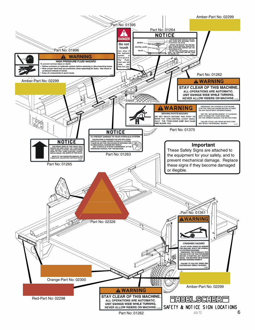
Part No: 01395
Part No: 01261
Part No: 01370
Part No: 01896
Part No: 01262
Part No: 01263
Part No: 01265
Part No: 01264
Red-Part No: 02298
Orange-Part No: 02300
Part No: 02326
Amber-Part No: 02299
Part No: 01262
Amber-Part No: 02299
Amber-Part No: 02299
ImportantThese Safety Signs are attached to the equipment for your safety, and to prevent mechanical damage. Replace these signs if they become damaged or illegible.
6
Installation and Pre-operation
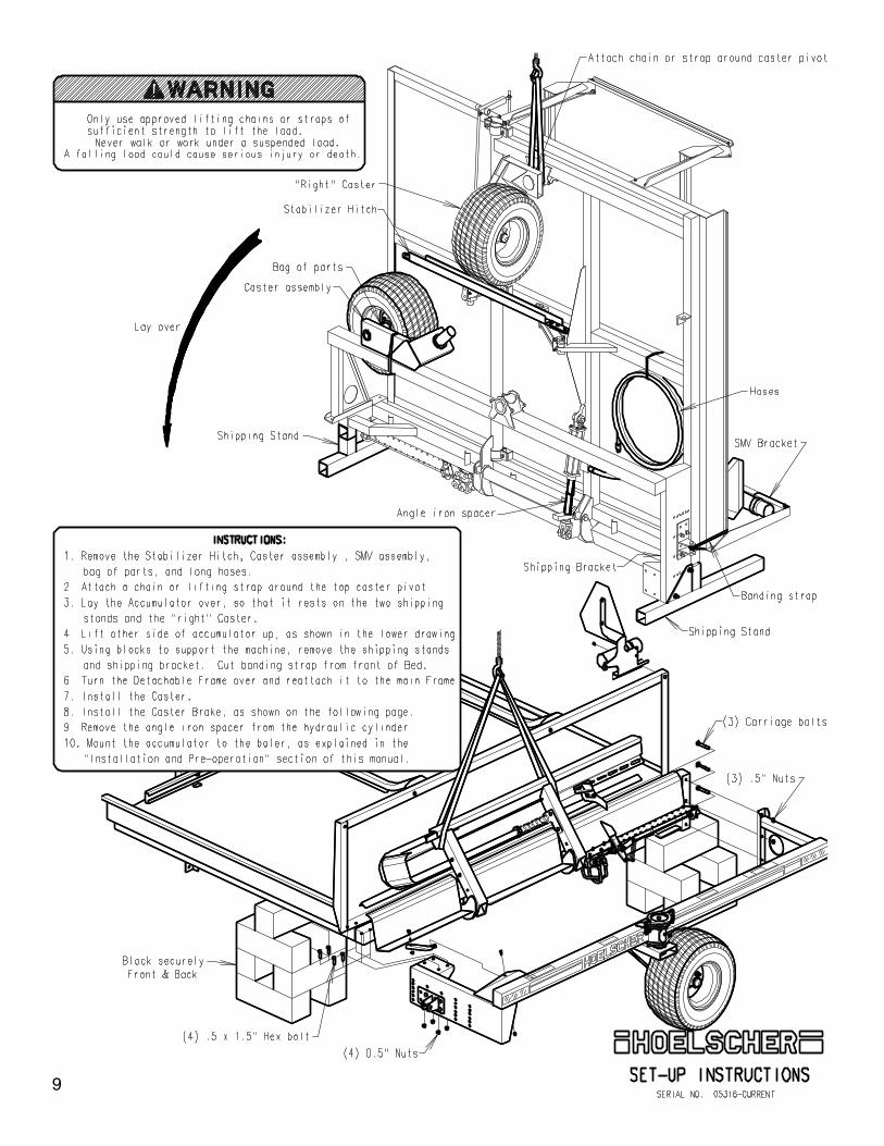
1. Assemble the accumulator, as shown on page 9 and 10.
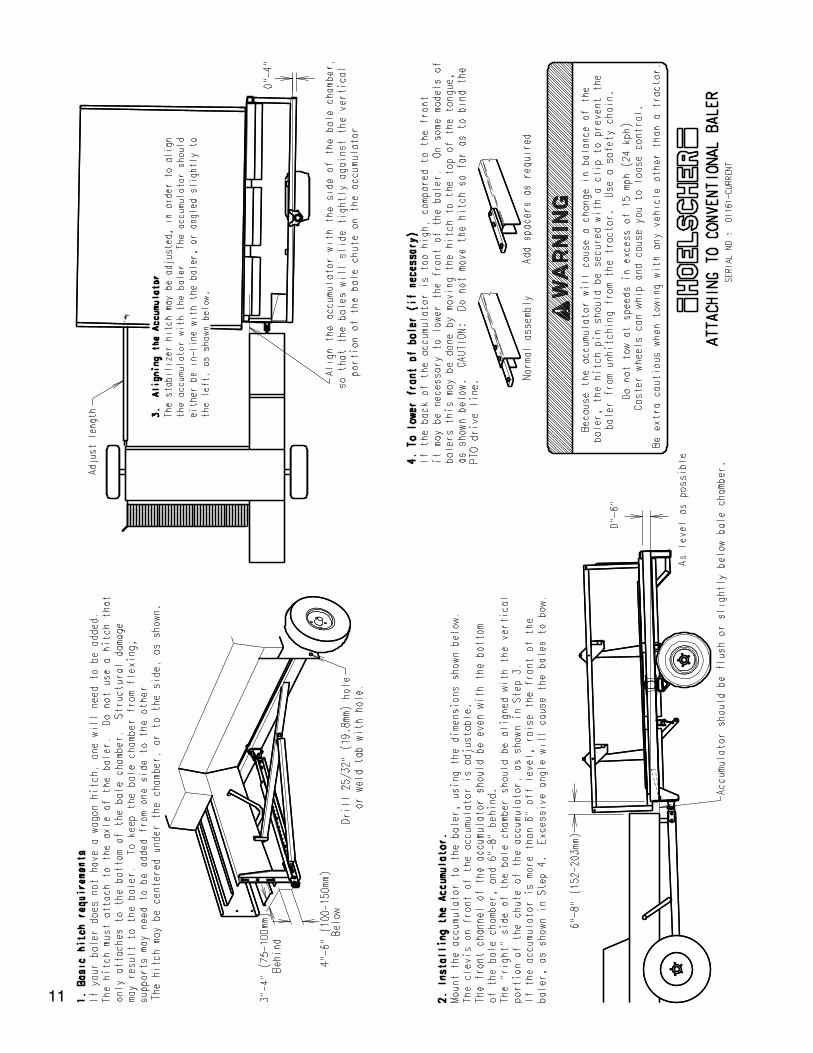
2. Mount the accumulator to the baler with a hitch as described on page 11 or 12, depending on the type of baler that you are using.
3. Route the hydraulic hoses to the tractor’s remote quick couplers (or to the optional Hydraulic Power Pack). Secure the hoses to the baler, so as to avoid cutting, crushing, or scuffing. Do not attach near moving parts, such as the needle carriage, pick-up, PTO, or where they might rub the ground.
4. Check all bolts and hydraulic fittings for tightness.
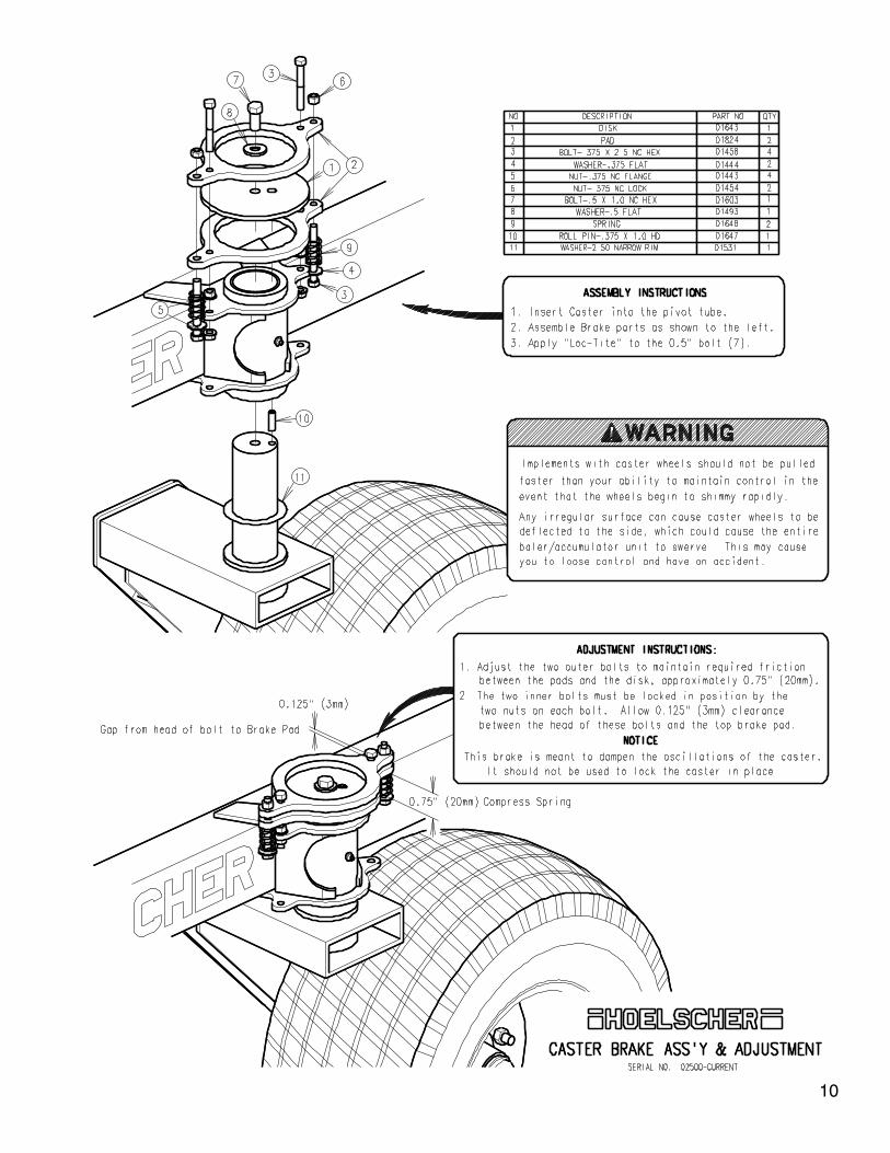
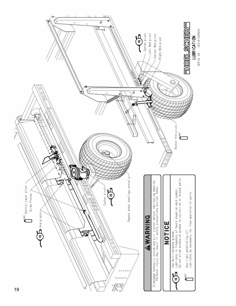
5. Grease all lubrication points. See “Lubrication”, page 19.
6. Adjust the accumulator for the desired length of bale, as shown on page 13. If the Arm Control Lever must be relocated to allow for a different length of bale, the Detent must also be moved accordingly, see page 14. Since there is no oil in the hydrauilc system at this time, the Push-over Arm may be raised by hand to verify adjustments. This is a good time to study the operation of the Detent in relation to the Arm Control Lever. This is the most critical adjustment on the machine. Lower the Push-over Arm and check adjustment of the retractable Piston in the Arm. For most condi-tions, it should be set to the dimensions shown on page 33.
7. If any options are to be installed, do so now. i.e.: 15 Bale Conversion, Side-hill Kit, Hold-down Kit, or Bed Extension Kit.
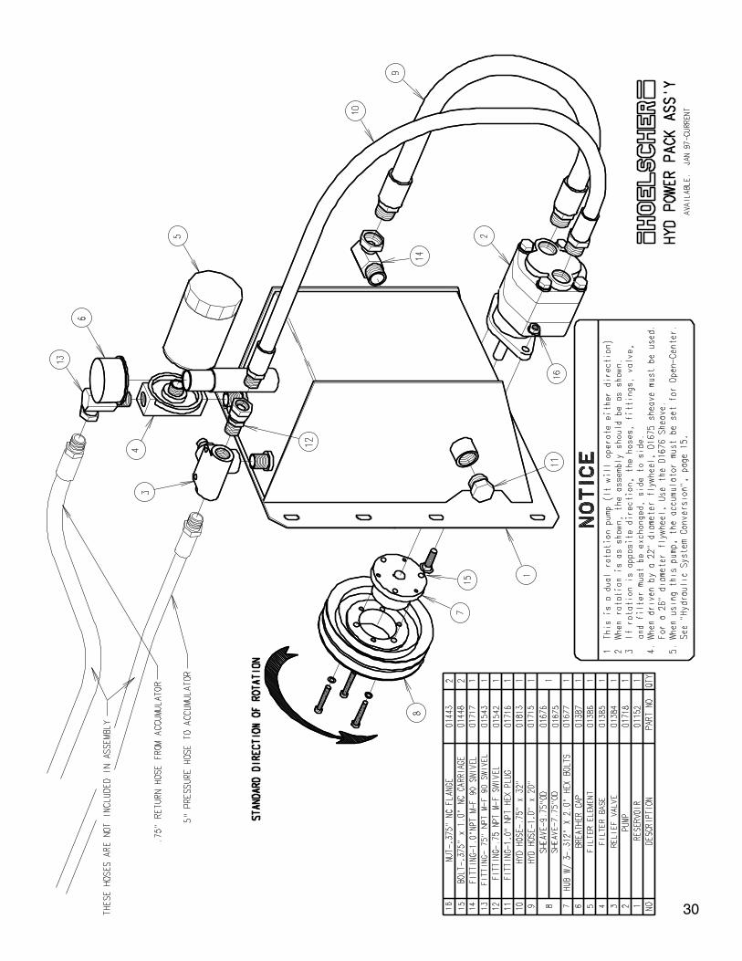
8. Refer to the tractor’s operator’s manual to find the type of hydraulic system the tractor is equipped with, “open-center” or “closed-center”. Set the accumulator appropriately, as shown on page 15.If your tractor uses a “load-sensing” hydraulic system, it is usually best to set the accumulator for “open-cen-ter”. With these systems, it is important to adjust the tractor’s hydraulic flow control for the minimum amount of oil required for proper operation of the Push-over Arm. Higher flow rates will cause excessive heat in the hydraulic system. If in doubt of which system your tractor has, try both settings, and use the setting that puts the least load on the tractor. If your tractor has a “priority valve”, this should be used to power the accumulator.
Incorrect setting of the accumulator’s hydraulic system may result in damage to the tractor’s hydraulic system.
9. Connect the hydraulic hoses to their respective couplers on the tractor. The smaller hose is the “pres-sure”, and the large hose is the “Return”. With everyone standing clear, energize the hydraulic system by holding the tractor’s hydraulic control lever “back”.
It will take a few seconds to purge air from the system. Let the oil circulate for 30 seconds. If the Push-over Arm or Bed of the accumulator moves, immediately move the tractor’s hydraulic control lever to neutral. No part of the accumulator should move at this time. If the Push-over Arm did raise, reverse the hoses at the tractor’s couplers. Each time the hydraulic system is energized, verify that the hoses are connected to the tractor, so that no part of the accumulator moves.
It is best if the hoses are connected to the tractor, so that the hydraulic control lever is pulled “back” to energize the accumulator. The reason for this is, if the hydraulic control lever is pushed “forward”, the lever could inadvertantly be pushed it into “float” position. In “float”, the hydraulic system does not provide flow.
7
Pre-operation, cont’d
If the hoses are connected to the tractor incorrectly, or if the tractor’s hydraulic control lever is moved in the wrong direction, the Push-over Arm and Bed will raise, and could cause severe damage. It is important to always connect the hoses to the tractor correctly, and pull “back” on the hydraulic control lever.
In operation, the tractor’s hydraulic lever will need to be secured in the “back” position. If the tractor does not have a means of locking the control lever back, a tarp strap may be used.
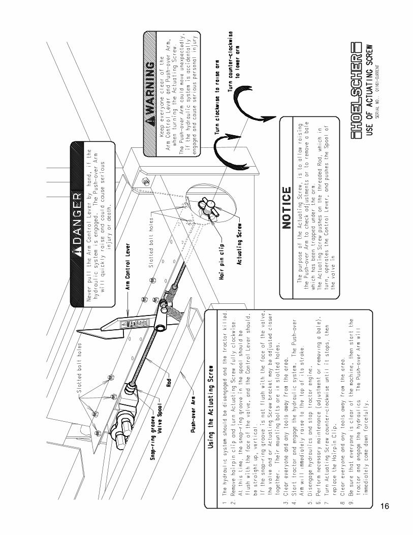
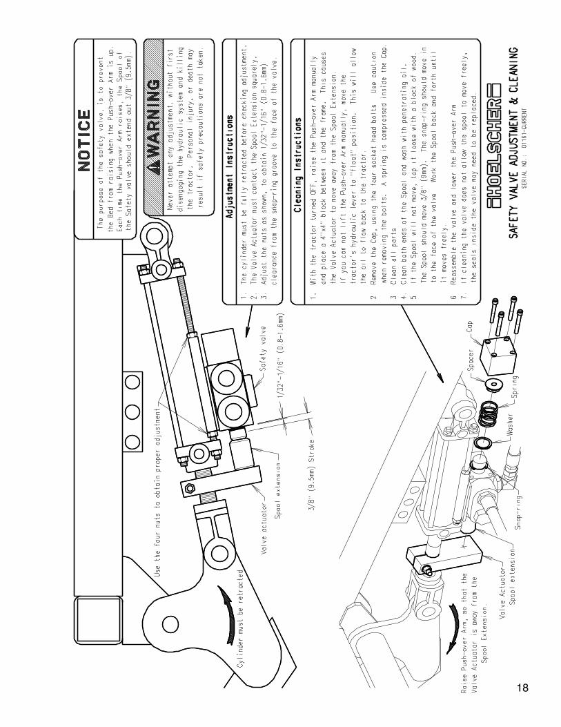
10. Disengage the hydraulic system and kill the tractor. Follow the procedure on page 16, “Use of Actuat-ing Screw”. Be sure that everyone is clear of the machine. Start the tractor and engage the hydraulic system. The Push-over Arm will raise quickly and forcefully to the top of its stroke. Disengage the hydraulic system and kill the tractor, set the brake and remove the ignition key. Verify that the Spool of the Safety Valve has extended out, as shown on page 18. If not, it may be stuck from setting without oil in it for some time. If necessary, remove the square block on back of the Safety Valve and tap on the spool to loosen it. Turn the Actuating Screw counter-clockwise fully and install the hairpin clip. With everyone clear of the accumulator, start the tractor and engage the hydraulic system. The Push-over Arm will return down quickly and forcefully.
Never touch the Arm Control Lever by hand if the tractor is running. If the hydraulic system is engaged, the Push-over Arm will move quickly and could cause serious personal injury or death.
11. Check for any leaks in the hydraulic system. Due to the volume of hydraulic oil used to fill the hoses, valves, and cylinders of the accumulator, it will be necessary to fill the tractor’s hydraulic reservoir.
12. Check for proper tire inflation. Maximum pressure is 30 psi (207 kPa). Lower pressure may be used to allow for a smoother ride. Minimum pressure provides for a rolling radius (distance from the ground to the center of the spindle) of 10.9” (277mm) when loaded.
13. It is the responsibility of the customer to know the lighting and marking requirements of the local high-way authorities, and to maintain the equipment to provide compliance with the regulations. Add extra lights when transporting at night or during periods of limited visibility.
14. With steps 1 through 13 completed, the accumulator should now be ready for final adjustments, which are best made in the field.
8
9
10
11
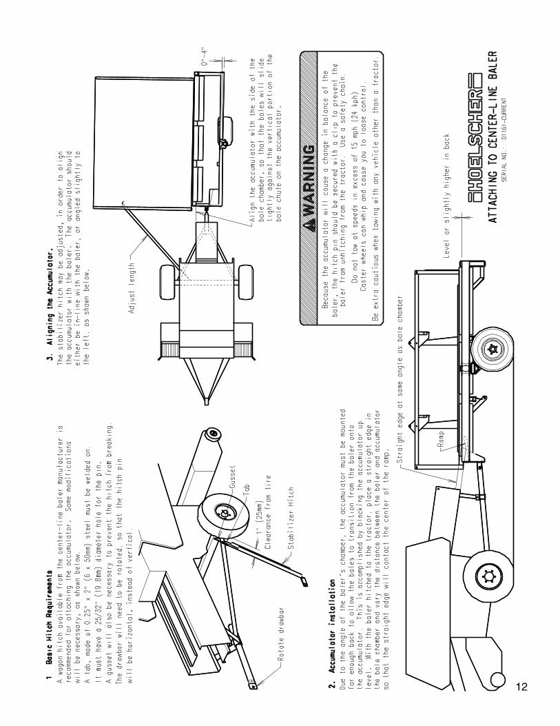
12
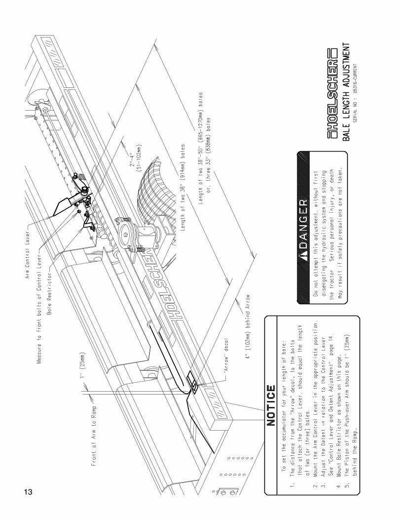
13
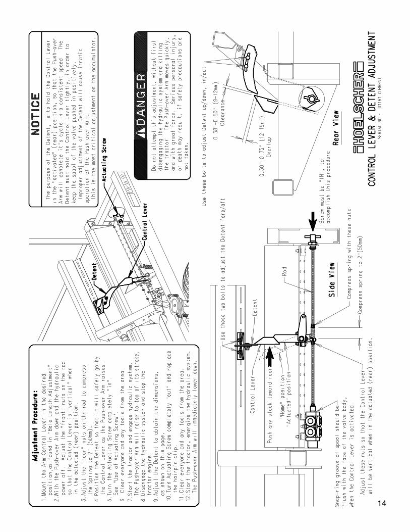
14
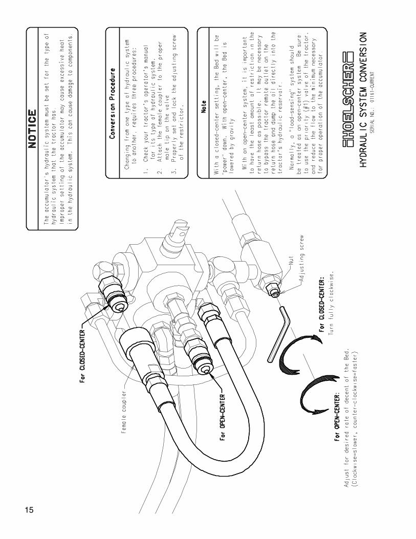
15
16
17
18
19
20
Operation
1. When in the field and everyone is clear of the machine, start the baler and energize the hydraulic system. Always watch the accumulator when energizing the hydraulic system to verify that the hydraulic hoses are attached properly to the tractor. Nothing on the accumulator should move at this time. The tractor’s hydraulic control lever will need to be secured in the “back” position. If there is no provision to lock the lever back, a tarp strap may be used.
2. Start baling and proceed until the first bale almost reaches the Arm Control Lever. Stop baling, disen-gage the hydraulic system, stop the baler, and turn off the tractor.
3. Check to see if the bale length is correct and meets the conditions shown in “Bale Length” on page 13. If the Arm Control Lever of the accumlator has been set to the desired bale length, adjust the bale length on the baler as necessary to maintain that length.
If it appears that the combined length of both bales is more than 8” (203mm) from the desired length, remove those bales before resuming baling. These bales will need to be rebaled to the proper length.
Never attempt any adjustment while the hydraulic system is energized or if the tractor is run-ning. Serious personal injury or death could result.
4. Adjust the speed of the Push-over Arm as necessary. For tractors with adjustable hydraulic flow con-trol, use only enough speed to make the Push-over Arm cycle without catching the next bale out of the baler, as the Arm returns down. Excessive flow will cause heat build up in the hydraulic system and the bales will be thrown, rather than placed into position. If the tractor does not have a flow control, use the Needle Valve shown on page 20.
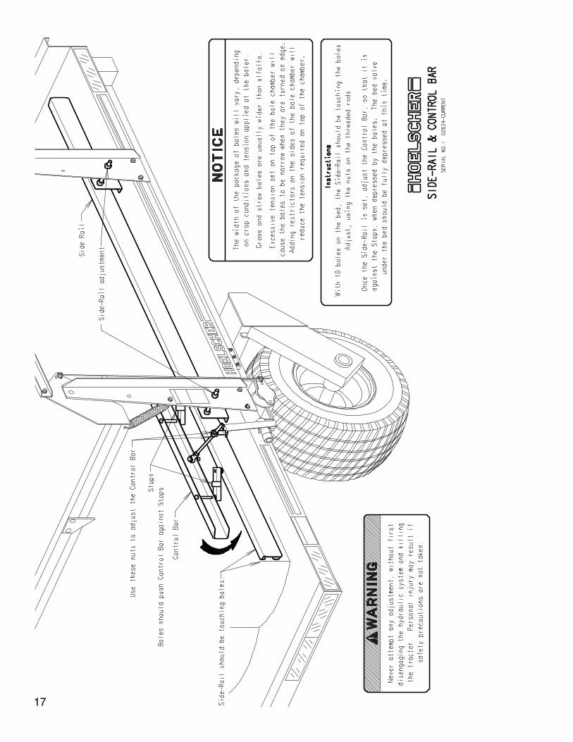
5. Start the tractor and baler, and engage the hydraulic system. Resume baling until 10 (or 15) bales are on the accumulator’s bed. If the Bed does not dump, or if the bales do not slide off evenly, stop baling. Disengage the hydraulic system, stop the baler, and kill the tractor. Check adjustment of the Side-rail and Bed Control Bar. See page 17.
6. Adjust rate of decent of the Bed, as shown on page 15. It should return down slowly, but before the next bales are ready to be loaded onto the Bed. With a closed-center hydraulic system, the restrictor should be completely “in”.
7. With the above adjustments verified, the accumulator should now be ready for use. The baler will pro-duce bales of varying length depending on crop conditions, and will require periodic adjustment to maintain a length compatable with the accumulator’s setting. Also, when baling different crops, the Bed Side-rail and Control Bar may need to be readjusted. See the “Troubleshooting” section of this manual if you experience difficulties in operation.
8. If a bale should get caught under the Push-over Arm, stop, disengage the hydraulic system, stop the baler, and kill the tractor. The Push-over Arm should be raised, so that the bale can be safely removed, by fol-lowing the procedures explained in “Actuating Screw”, page 16.
Never attempt to remove the bale while the hydrauic system is energized, or if the tractor is running. Serious personal injury or death could result.
This condition is usually caused by the bale length being shorter than the setting of the accumulator, or the speed of the Push-over Arm is too slow. Adjust the bale length of the baler accordingly, or increase hydraulic flow from the tractor (or adjust the Needle Valve).
21
Operation, continued
9. If a bale should get wedged between the Push-over Arm and Mount Tube above the Bed, or the front upright, stop baling. Disengage the hydraulic system, stop the baler and kill the tractor. If the bale can not be manually dislodged, it will need to be cut and the crop material will need to be removed.
Do not put any part of your body within the movement area of the Push-over Arm. When the material is removed, the Arm could move and cause serious personal injury or death. Always verify that the hydraulic system has been disengaged and the tractor turned off.
This condition is usually caused by the bale length being longer than the setting of the accumulator, or the Push-over Arm moving too fast. Adjust the bale length of the baler accordingly, or decrease hydraulic flow from the tractor. If the tractor does not have a flow control, use the Needle Valve on the accumulator as shown on page 20.
10. If the Push-over Arm does not cycle at a consistant rate, the Detent is probably not holding the Control Lever back properly. Check adjustment of the Arm Control Lever and Detent, page 14, by using the procedure explained in Use of Actuating Screw, page 16.
11. Always disengage the hydraulic system, stop the baler, kill the tractor, set parking brake, and remove the ignition key before leaving the tractor.
12. See Troubleshooting, pages 23 and 24 for other problems encountered.
22
Tro
ub
lesh
oo
tin
g
S
ymp
tom
Cau
se
Rem
edy
Bal
e ca
tche
s on
fron
t cor
ner
of b
ed, a
s th
e P
ush-
over
1.
Bal
e le
ngth
is to
o lo
ng.
1. S
hort
en b
ale
leng
th o
f bal
er.
Arm
is p
ushi
ng th
e ba
les
onto
the
bed.
2.
Arm
Con
trol
Lev
er is
too
far
forw
ard.
2.
Mov
e A
rm C
ontr
ol L
ever
rea
rwar
d. P
age
13
Bal
e is
trap
ped
unde
r pu
sh-o
ver
arm
, as
the
arm
is
1.
Bal
e le
ngth
is to
o sh
ort.
1. In
crea
se b
ale
leng
th o
f bal
er.
retu
rnin
g do
wn.
2. A
rm c
ontr
ol le
ver
is to
o fa
r ba
ck.
2.
Mov
e A
rm C
ontr
ol L
ever
forw
ard.
Pag
e 13
3.
Pus
h-ov
er A
rm is
mov
ing
too
slow
ly.
3. In
crea
se h
ydra
ulic
flow
from
the
trac
tor.
4.
Tra
velin
g to
o fa
st fo
r hy
drau
lic fl
ow.
4. R
educ
e tr
avel
spe
ed.
Bal
es a
re b
ent a
s th
ey s
lide
onto
the
accu
mul
ator
.
1. T
oo m
uch
angl
e be
wee
n th
e ba
ler
and
accu
mla
tor.
1.
Lev
el th
e ba
ler
as m
uch
as p
ossi
ble.
2. In
crea
se d
ista
nce
betw
een
bale
r an
d ac
cum
ulat
or.
Bal
e co
ntac
ts th
e A
rm C
ontr
ol L
ever
, but
the
Pus
h-ov
er
1. H
ydra
ulic
sys
tem
is n
ot o
pera
ting.
1. E
ngag
e th
e tr
acto
r’s h
ydra
ulic
sys
tem
.A
rm d
oes
not m
ove.
2.
Con
trol
Lev
er li
nkag
e is
mal
func
tioni
ng.
2. C
heck
link
age
for
dam
age
or b
indi
ng.
Pus
h-ov
er A
rm r
aise
s pa
rt w
ay, t
hen
retu
rns
dow
n, o
r
1. T
he D
eten
t is
not h
oldi
ng th
e A
rm C
ontr
ol L
ever
bac
k 1.
Adj
ust A
rm C
ontr
ol L
ever
and
Det
ent,
page
14
cont
inue
s up
slo
wly
.
pos
itive
ly fo
r th
e fu
ll st
roke
of t
he P
ush-
over
Arm
.
Pus
h-ov
er A
rm r
aise
s pa
rt w
ay, t
hen
retu
rns
back
dow
n 1.
A b
ale
slid
ing
back
may
brie
fly c
onta
ct th
e A
rm C
ontr
ol
1. V
erify
that
the
four
bol
ts h
oldi
ng th
e A
rm V
alve
are
and
then
rai
ses
agai
n im
med
iate
ly.
Lev
er p
rem
atur
ely.
As
the
Pus
h-ov
er A
rm s
tart
s up
, the
inst
alle
d w
ith th
e he
ad o
n bo
ttom
See
pag
e 16
bal
e sl
ides
forw
ard,
rel
easi
ng th
e C
ontr
ol L
ever
. W
hen
2. B
ale
Res
tric
tor
shou
ld b
e m
ount
ed 2
”-4”
the
bale
r m
akes
its
next
str
oke,
the
bale
aga
in a
ctiv
ates
(50
-100
mm
) ah
ead
of th
e A
rm C
ontr
ol L
ever
.
th
e A
rm C
ontr
ol L
ever
. T
his
usua
lly o
ccur
s in
ext
rem
ely
S
ee p
age
13
d
ry, s
lick
cond
ition
s.
Pus
h-ov
er A
rm d
oes
not r
etur
n do
wn.
1.
The
Det
ent i
s no
t rel
easi
ng th
e A
rm C
ontr
ol L
ever
.
1. A
djus
t as
show
n on
pag
e 14
.
2. T
he A
rm v
alve
or
linka
ge is
stic
king
.
2.
Cle
an o
r ad
just
val
ve a
nd li
nkag
e as
nec
essa
ry.
3.
The
Saf
ety
Val
ve is
stic
king
.
3. C
lean
and
adj
ust a
s sh
own
on p
age
18.
Bal
es d
o no
t set
pro
perly
on
Bed
.
1. P
ush-
over
Arm
doe
s no
t pus
h th
e ba
les
far
enou
gh.
1. D
eten
t is
not h
oldi
ng A
rm C
ontr
ol s
uffic
ient
ly.
2.
Pus
h-ov
er A
rm m
oves
too
fast
, and
thro
ws
the
bale
s.
2. R
educ
e hy
drau
lic fl
ow fr
om th
e tr
acto
r, or
adj
ust
th
e N
eedl
e va
lve,
as
show
n on
pag
e 20
.
Bal
es d
o no
t piv
ot p
rope
rly w
hile
bei
ng p
ushe
d to
the
Bed
. 1.
Bal
es a
re n
ot c
lose
eno
ugh
to th
e ve
rtic
al p
art o
f the
1.
Mov
e th
e en
tire
accu
mul
ator
to th
e le
ft as
far
as
B
ale
Chu
te o
f the
acc
umul
ator
.
p
ossi
ble,
in r
elat
ion
to th
e ba
ler.
Pag
es 1
1 an
d 12
.
2. P
ush-
over
Arm
mov
es to
o fa
st, a
nd th
row
s th
e ba
les.
2.
Red
uce
hydr
aulic
flow
from
the
trac
tor,
or a
djus
t
the
Nee
dle
valv
e, a
s sh
own
on p
age
20.
Bal
es s
lide
on th
e B
ed a
nd c
onta
ct th
e B
ed C
ontr
ol B
ar
1. W
orki
ng o
n ex
cess
ive
incl
ine.
1. T
rave
l in
othe
r di
rect
ion
if po
ssib
le.
befo
re th
e B
ed is
fully
load
ed.
2.
Pus
h-ov
er A
rm is
ope
ratin
g to
o fa
st.
2. R
educ
e hy
drau
lic fl
ow fr
om th
e tr
acto
r, or
adj
ust
3. R
ever
se th
e D
ogs
on th
e H
old-
dow
n B
ars,
so
that
th
e ba
les
cont
act t
he v
ertic
al s
ide,
inst
ead
of th
e
tape
red
side
.
23

Trou
bles
hoot
ing,
con
t’d
Bal
es fa
ll ba
ck o
nto
the
Pus
h-ov
er A
rm, a
fter
bein
g pl
aced
1.
The
Pus
h-ov
er A
rm d
id n
ot tr
avel
thro
ugh
it’s
full
cycl
e,
1. C
heck
adj
ustm
ent o
f the
Arm
Con
trol
Lev
er a
ndon
the
Bed
.
a
nd th
e ba
les
wer
e no
t com
plet
ely
on th
e B
ed.
Det
ent.
See
pag
e 14
.
2. W
orki
ng o
n ex
cess
ive
incl
ine.
2. In
stal
l Sid
e-hi
ll K
it, a
s sh
own
on p
age
27.
Pus
h-ov
er A
rm o
pera
tes
inco
nsis
tant
ly.
1. A
rm C
ontr
ol L
ever
and
Det
ent a
re n
ot a
djus
ted
prop
erly
. 1.
Adj
ust a
s sh
own
on p
age
14.
Bal
es c
atch
on
Upr
ight
, on
left
side
of B
ed w
hile
dum
ping
. 1.
The
bal
es w
ere
not c
ompl
etel
y on
the
Bed
. 1.
Ver
ify th
at th
e P
ush-
over
Arm
is m
akin
g its
full
c
ycle
. A
djus
t as
nece
ssar
y. S
ee p
age
14.
2.
Wor
king
on
exce
ssiv
e in
clin
e.
2.
Inst
all S
ide-
hill
Kit,
as
show
n on
pag
e 27
.
3. A
ccum
ulat
or is
not
pro
perly
alig
ned
with
the
bale
r.
3. T
he a
ccum
ulat
or s
houl
d be
mou
nted
, so
that
the
r
ear
is to
the
“left”
. S
ee p
age
11 o
r 12
.
The
Bed
rai
ses
too
slow
ly, a
llow
ing
the
bale
s to
sep
arat
e 1.
Bed
Con
trol
Bar
is n
ot fu
lly d
epre
ssed
.
1.
Che
ck a
djus
tmen
t as
show
n on
pag
e 17
.
2. In
suffi
cien
t hyd
raul
ic fl
ow to
the
Bed
cyl
inde
r.
2. C
heck
the
Res
tric
tor
on th
e B
ed v
alve
for
debr
is
that
may
be
bloc
king
flow
.
Bed
will
not
rai
se.
1. B
ales
hav
e no
t con
tact
ed th
e B
ed C
ontr
ol B
ar.
1.
Adj
ust S
ide-
rail
and
Con
trol
Bar
. P
age
17.
2.
Bal
es a
re n
ot p
ushe
d fa
r en
ough
to c
onta
ct C
ontr
ol B
ar.
2. C
heck
adj
ustm
ent o
f the
Arm
Con
trol
Lev
er a
nd
Det
ent.
See
pag
e 14
.
3. S
afet
y V
alve
is n
ot b
eing
dep
ress
ed b
y th
e V
alve
Act
uato
r. 3.
Che
ck o
pera
tion
of th
e S
afet
y V
alve
. P
age
18.
Bed
rai
ses
but w
ill n
ot r
etur
n do
wn.
1.
Bed
Con
trol
Bar
or
Bed
Val
ve a
re s
ticki
ng.
1. In
spec
t, cl
ean
and
lubr
icat
e.
2. R
estr
ictio
n in
the
retu
rn h
ose
to th
e tr
acto
r. (
On
Ope
n-
2. R
epla
ce q
uick
-cou
pler
on
retu
rn h
ose
and
chec
k
c
ente
r sy
stem
s, th
e B
ed is
not
pow
ered
dow
n)
for
dam
aged
hos
es b
etw
een
the
Bed
Val
ve a
nd
R
estr
ictio
ns a
re m
ost l
ikel
y ca
used
by
a qu
ick-
coup
ler,
or
th
e tr
acto
r.
a
dam
aged
hos
e.
Bed
dec
ends
too
slow
ly.
1. R
estr
icto
r is
res
tric
ting
too
muc
h. I
f the
acc
umul
ator
is s
et
1. A
djus
t Res
tric
tor,
as s
how
n on
pag
e 15
.
fo
r op
en-c
ente
r, th
e B
ed n
eeds
a fr
ee r
ever
se fl
ow.
Bal
es c
atch
on
Bed
Con
trol
Bar
, as
the
Bed
is d
umpi
ng.
1. C
ontr
ol B
ar is
not
flus
h w
ith th
e S
ide-
rail.
1.
Mov
e th
e S
ide
Rai
l in,
tow
ards
the
bale
s. T
hen
r
eadj
ust t
he C
ontr
ol B
ar, a
s sh
own
on p
age
17.
Bal
e fa
lls o
ut o
f bal
e ch
ambe
r of
cen
ter-
line
bale
r, an
d
1. D
ue to
the
dist
ance
bet
wee
n th
e ba
ler
and
accu
mul
ator
, 1.
Add
res
tric
tors
(w
edge
s) in
side
the
cham
ber,
is c
augh
t und
er th
e P
ush-
over
Arm
.
bal
es le
ss th
an 3
8” (
965m
m)
are
rele
ased
from
the
as
near
the
rear
as
poss
ible
. P
refe
rabl
y, w
ithin
cha
mbe
r pr
emat
urel
y. (
Cen
ter-
line
bale
rs o
nly)
1
” (25
mm
).
24
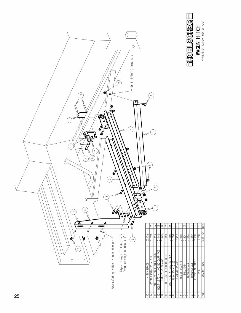
25
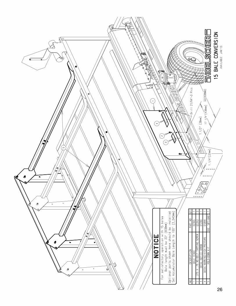
26
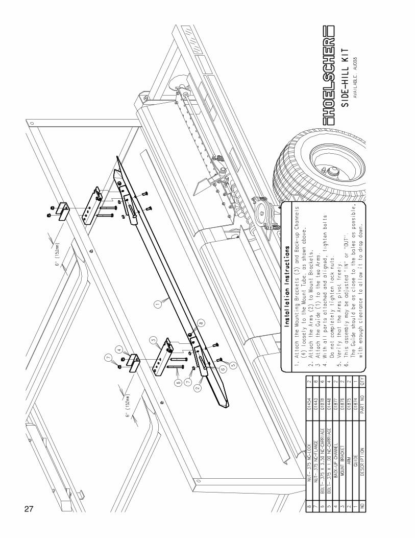
27
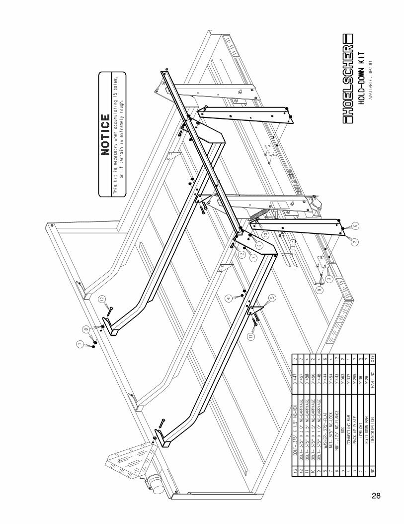
28
29
30
31
32
33
34
35
36

Bolt Torque Specifications
The table below gives correct torque values for various bolts and capscrews used for attaching flat surfaces together. Tighten all bolts to these specifications, unless otherwise noted. Check tightness of bolts periodi-cally. Replace hardware of the same strength bolt. Torque values shown are for non-lubricated threads. Do not grease or oil bolts unless otherwise specified. When using locking elements, increase torque values by 5%. Lock nuts used to adjust devices such as a spring, should not be torqued to these values.
Bolt Size Grade 2 Grade 5 Grade 8 in-tpi ft.lb. Nm ft.lb. Nm ft.lb. Nm
1/4-20 5.6 7.4 8 11 12 161/4-28 6 8.5 10 13 14 185/16-18 11 15 17 24 25 335/16-24 13 17 19 26 27 373/8-16 20 27 31 42 44 593/8-24 22 31 35 47 49 677/16-14 32 43 49 67 70 957/16-20 36 49 55 75 78 1051/2-13 49 66 76 105 105 1451/2-20 55 75 85 115 120 1659/16-12 70 95 110 150 155 2109/16-18 79 105 120 165 170 2355/8-11 97 130 150 205 210 2855/8-18 110 150 170 230 240 3253/4-10 170 235 265 360 375 5103/4-16 190 260 295 405 420 5707/8-9 165 225 430 585 605 8207/8-14 185 250 475 640 670 9051-8 250 340 645 875 910 12301-12 275 370 705 955 995 1350
Tire Inflation
12-12x12.00, 6 ply: 30 psi (207 kPa) maximum
Lower pressure may be used to allow for a smoother ride. Minimum pressure provides a rolling radius (dis-tance from ground to center of wheel) of 10.9” (277mm).
Tire Warranty Information
All tires are warranted by the original manufacturer of the tire. For assistance or information, contact your nearest farm tire retailer that sells the appropriate brand.
37

38

39


HOELSCHER, INC - 312 S Main St - Bushton, KS 67427620-562-3575
www.hoelscherinc.com
COMMERCIAL PRODUCTS