Embed Size (px)
Citation preview

GTH2550Owner’s Manual

2
Safe Operation Practices for Ride-On MowersIMPORTANT: THIS CUTTING MACHINE IS CAPABLE OF AMPUTATING HANDS AND FEET AND THROWING OBJECTS.FAILURE TO OBSERVE THE FOLLOWING SAFETY INSTRUCTIONS COULD RESULT IN SERIOUS INJURY OR DEATH.
SAFETY RULES
I. GENERAL OPERATION• Read, understand, and follow all instructions in the
manual and on the machine before starting.• Only allow responsible adults, who are familiar with the
instructions, to operate the machine.• Clear the area of objects such as rocks, toys, wire, etc.,
which could be picked up and thrown by the blade.• Be sure the area is clear of other people before mowing.
Stop machine if anyone enters the area.• Never carry passengers.• Do not mow in reverse unless absolutely necessary.
Always look down and behind before and while backing.• Be aware of the mower discharge direction and do not
point it at anyone. Do not operate the mower withouteither the entire grass catcher or the guard in place.
• Slow down before turning.• Never leave a running machine unattended. Always turn
off blades, set parking brake, stop engine, and removekeys before dismounting.
• Turn off blades when not mowing.• Stop engine before removing grass catcher or unclog-
ging chute.• Mow only in daylight or good artificial light.• Do not operate the machine while under the influence of
alcohol or drugs.• Watch for traffic when operating near or crossing road-
ways.• Use extra care when loading or unloading the machine
into a trailer or truck.• Data indicates that operators, age 60 years and above,
are involved in a large percentage of riding mower-related injuries. These operators should evaluate theirability to operate the riding mower safely enough toprotect themselves and others from serious injury.
II. SLOPE OPERATIONSlopes are a major factor related to loss-of-control andtipover accidents, which can result in severe injury or death.All slopes require extra caution. If you cannot back up theslope or if you feel uneasy on it, do not mow it.
DO:• Mow up and down slopes, not across.• Remove obstacles such as rocks, tree limbs, etc.• Watch for holes, ruts, or bumps. Uneven terrain could
overturn the machine. Tall grass can hide obstacles.• Use slow speed. Choose a low gear so that you will not
have to stop or shift while on the slope.• Follow the manufacturer’s recommendations for wheel
weights or counterweights to improve stability.• Use extra care with grass catchers or other attach-
ments. These can change the stability of the machine.• Keep all movement on the slopes slow and gradual. Do
not make sudden changes in speed or direction.• Avoid starting or stopping on a slope. If tires lose
traction, disengage the blades and proceed slowlystraight down the slope.
DO NOT:• Do not turn on slopes unless necessary, and then, turn
slowly and gradually downhill, if possible.• Do not mow near drop-offs, ditches, or embankments.
The mower could suddenly turn over if a wheel is over theedge of a cliff or ditch, or if an edge caves in.
• Do not mow on wet grass. Reduced traction could causesliding.
• Do not try to stabilize the machine by putting your footon the ground.
• Do not use grass catcher on steep slopes.
III. CHILDRENTragic accidents can occur if the operator is not alert to thepresence of children. Children are often attracted to themachine and the mowing activity. Never assume thatchildren will remain where you last saw them.• Keep children out of the mowing area and under the
watchful care of another responsible adult.• Be alert and turn machine off if children enter the area.• Before and when backing, look behind and down for
small children.• Never carry children. They may fall off and be seriously
injured or interfere with safe machine operation.• Never allow children to operate the machine.• Use extra care when approaching blind corners, shrubs,
trees, or other objects that may obscure vision.
IV. SERVICE• Use extra care in handling gasoline and other fuels.
They are flammable and vapors are explosive.- Use only an approved container.- Never remove gas cap or add fuel with the engine
running. Allow engine to cool before refueling. Donot smoke.
- Never refuel the machine indoors.- Never store the machine or fuel container inside
where there is an open flame, such as a water heater.• Never run a machine inside a closed area.• Keep nuts and bolts, especially blade attachment bolts,
tight and keep equipment in good condition.• Never tamper with safety devices. Check their proper
operation regularly.• Keep machine free of grass, leaves, or other debris
build-up. Clean oil or fuel spillage. Allow machine to coolbefore storing.
• Stop and inspect the equipment if you strike an object.Repair, if necessary, before restarting.
• Never make adjustments or repairs with the enginerunning.
• Grass catcher components are subject to wear, dam-age, and deterioration, which could expose moving partsor allow objects to be thrown. Frequently check compo-nents and replace with manufacturer's recommendedparts, when necessary.
• Mower blades are sharp and can cut. Wrap the blade(s)or wear gloves, and use extra caution when servicingthem.
• Check brake operation frequently. Adjust and serviceas required.

3
• Be sure the area is clear of other people before mowing.Stop machine if anyone enters the area.
• Never carry passengers or children even with theblades off.
• Do not mow in reverse unless absolutely necessary.Always look down and behind before and while backing.
• Never carry children. They may fall off and be seriouslyinjured or interfere with safe machine operation.
• Keep children out of the mowing area and under thewatchful care of another responsible adult.
• Be alert and turn machine off if children enter the area.• Before and when backing, look behind and down for
small children.• Mow up and down slopes (15° Max), not across.• Remove obstacles such as rocks, tree limbs, etc.• Watch for holes, ruts, or bumps. Uneven terrain could
overturn the machine. Tall grass can hide obstacles.• Use slow speed. Choose a low gear so that you will not
have to stop or shift while on the slope.• Avoid starting or stopping on a slope. If tires lose
traction, disengage the blades and proceed slowlystraight down the slope.
• If machine stops while going uphill, disengage blades,shift into reverse and back down slowly.
• Do not turn on slopes unless necessary, and then, turnslowly and gradually downhill, if possible.
SAFETY RULESSafe Operation Practices for Ride-On Mowers
IMPORTANT: THIS CUTTING MACHINE IS CAPABLE OF AMPUTATING HANDS AND FEET AND THROWING OBJECTS.FAILURE TO OBSERVE THE FOLLOWING SAFETY INSTRUCTIONS COULD RESULT IN SERIOUS INJURY OR DEATH.
Look for this symbol to point out importantsafety precautions. It means CAUTION!!!BECOME ALERT!!! YOUR SAFETY IS IN-VOLVED.
CAUTION: In order to prevent acciden-tal starting when setting up, transport-ing, adjusting or making repairs, alwaysdisconnect spark plug wire and placewire where it cannot contact spark plug.
WARNINGEngine exhaust, some of its constituents, and certainvehicle components contain or emit chemicals knownto the State of California to cause cancer and birthdefects or other reproductive harm.
WARNINGBattery posts, terminals and related accessories con-tain lead and lead compounds, chemicals known tothe State of California to cause cancer and birthdefects or other reproductive harm. Wash hands afterhandling.
CAUTION: Do not coast down a hill inneutral, you may lose control of the trac-tor.
CAUTION: Tow only the attachmentsthat are recommended by and complywith specifications of the manufacturerof your tractor. Use common sensewhen towing. Operate only at the lowestpossible speed when on a slope. Tooheavy of a load, while on a slope, isdangerous. Tires can lose traction withthe ground and cause you to lose controlof your tractor.

4
PRODUCT SPECIFICATIONS
GASOLINE CAPACITY 3.5 GALLONSAND TYPE: UNLEADED REGULAR
OIL TYPE (API-SF-SJ): SAE 10W30 (above 32°F)SAE 5W-30 (below 32°F)
OIL CAPACITY: W/ FILTER: 4.0 PINTSW/O FILTER: 3.75 PINTS
SPARK PLUG: CHAMPION RC12YC(GAP: .040")
GROUND SPEED (MPH): FORWARD: 0 – 5.8REVERSE: 0 – 2.1
TIRE PRESSURE: FRONT: 14 PSIREAR: 10 PSI
CHARGING SYSTEM: 16 AMPS @ 3600 RPM
BATTERY: AMP/HR: 30MIN. CCA: 240CASE SIZE: U1R
BLADE BOLT TORQUE: 27–35 FT. LBS.
CONGRATULATIONS on your purchase of a new tractor. Ithas been designed, engineered and manufactured to giveyou the best possible dependability and performance.
Should you experience any problem you cannot easilyremedy, please contact your nearest authorized servicecenter/department. We have competent, well-trained tech-nicians and the proper tools to service or repair this tractor.
Please read and retain this manual. The instructions willenable you to assemble and maintain your tractor properly.Always observe the “SAFETY RULES”.
CUSTOMER RESPONSIBILITIES• Read and observe the safety rules.• Follow a regular schedule in maintaining, caring for and
using your tractor.• Follow the instructions under “Customer Responsibili-
ties” and “Storage” sections of this owner’s manual.
WARNING: This tractor is equipped with an internal com-bustion engine and should not be used on or near anyunimproved forest-covered, brush-covered or grass-cov-ered land unless the engine’s exhaust system is equippedwith a spark arrester meeting applicable local or state laws(if any). If a spark arrester is used, it should be maintainedin effective working order by the operator.
A spark arrester for the muffler is available through yournearest authorized service center/department (See REPAIRPARTS section of this manual).
In the state of California the above is required by law (Section4442 of the California Public Resources Code). Other statesmay have similar laws. Federal laws apply on federal lands.
TABLE OF CONTENTSSAFETY RULES ........................................................ 2-3PRODUCT SPECIFICATIONS ....................................... 4CUSTOMER RESPONSIBILITIES ......................4, 17-20ASSEMBLY.............................................................. 6-10OPERATION............................................................11-16MAINTENANCE SCHEDULE....................................... 17
SERVICE AND ADJUSTMENTS .............................21-27STORAGE ................................................................... 28TROUBLESHOOTING .............................................29-30REPAIR PARTS ......................................................32-45WARRANTY ................................................................ 47

5
UNASSEMBLED PARTS
Steering Wheel Insert
Steering Wheel
Mower
(3) Retainer Springs (double loop)
(4) Retainer Springs (single loop)
(2) Front Link Assemblies
Gauge Wheels
(4) Washers 3/8 x 3/4 x 14 Ga.
(4) Wheels
(4) Adjusting Bars
(4) Retainer Springs (double loop)
(4) Clevis Pins
(4) Locknuts 3/8-16
(4) Shoulder Bolts
Nose Roller
Nose Roller NoseRollerBrackets
(2) Hex Bolts 3/8-16 x 1
(2) Washers 17/32 x 7/8 x 16 Ga.
(2) Nylon Locknuts 3/8-16
Steering Wheel
(1) Knob
(1) Washer 17/32 x 1-3/16 x 12 Gauge
Seat
(4) Brackets
(12) Carriage Bolts5/16-18 x 5/8
(12) Crownlock Nuts 3/16 x 8
(2) Keys
Keys Slope Sheet
(1) Oil Drain Tube For Future Use

6
ASSEMBLY
HOW TO SET UP YOUR TRACTOR
CHECK BATTERY (See Fig. 2)• Lift hood to raised position.• If this battery is put into service after month and year
indicated on label (label located between terminals)charge battery for minimum of one hour at 6-10 amps.(See "BATTERY" in CUSTOMER RESPONSIBILITIESsection of this manual for charging instructions).
Your new tractor has been assembled at the factory with exception of those parts left unassembled for shipping purposes. Toensure safe and proper operation of your tractor all parts and hardware you assemble must be tightened securely. Use thecorrect tools as necessary to insure proper tightness.
TOOLS REQUIRED FOR ASSEMBLYA socket wrench set will make assembly easier. Standardwrench sizes are listed.
(1) 1/2" wrench (1) Tire pressure gauge
(2) 9/16" wrenches (1) Utility knife
(1) 3/4" socket w/drive (1) Pliersratchet
When right or left hand is mentioned in this manual, it meanswhen you are in the operating position (seated behind thesteering wheel).
TO REMOVE TRACTOR FROM CARTON
UNPACK CARTON• Remove all accessible loose parts and parts cartons
from carton.• Cut, from top to bottom, along lines on all four corners
of carton, and lay panels flat.• Remove mower and packing materials.• Check for any additional loose parts or cartons and
remove.
BEFORE REMOVING TRACTOR FROMSKID
ATTACH STEERING WHEEL (See Fig. 1)• Remove hex bolt, lock washer and large flat washer from
steering shaft.• Position front wheels of the tractor so they are pointing
straight forward.• Slide the steering sleeve over the steering shaft.• Align tabs and press steering sleeve extension into
bottom of steering wheel.• Position steering wheel so cross bars are horizontal (left
to right) and slide onto steering wheel adapter.• Secure steering wheel to steering shaft with hex bolt,
lock washer and large flat washer previously removed.Tighten securely.
• Snap steering wheel insert into center of steering wheel.• Remove protective materials from tractor hood and grill.IMPORTANT: CHECK FOR AND REMOVE ANY STAPLESIN SKID THAT MAY PUNCTURE TIRES WHERE TRACTORIS TO ROLL OFF SKID.
FIG. 1
STEERING WHEELINSERT
STEERINGWHEELADAPTER
STEERINGSHAFT
STEERINGWHEEL
HEX BOLT
LOCKWASHER
FLAT WASHER
FIG. 2
LABEL
TABS
STEERINGSLEEVE
7
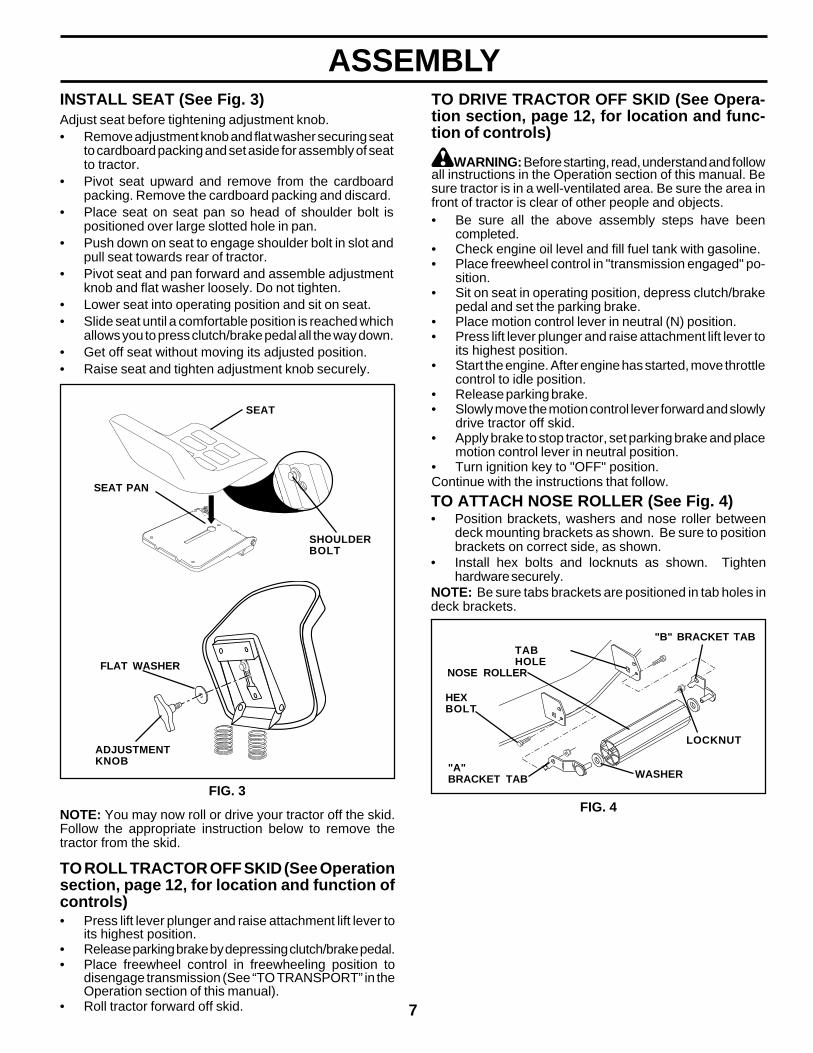
INSTALL SEAT (See Fig. 3)Adjust seat before tightening adjustment knob.• Remove adjustment knob and flat washer securing seat
to cardboard packing and set aside for assembly of seatto tractor.
• Pivot seat upward and remove from the cardboardpacking. Remove the cardboard packing and discard.
• Place seat on seat pan so head of shoulder bolt ispositioned over large slotted hole in pan.
• Push down on seat to engage shoulder bolt in slot andpull seat towards rear of tractor.
• Pivot seat and pan forward and assemble adjustmentknob and flat washer loosely. Do not tighten.
• Lower seat into operating position and sit on seat.• Slide seat until a comfortable position is reached which
allows you to press clutch/brake pedal all the way down.• Get off seat without moving its adjusted position.• Raise seat and tighten adjustment knob securely.
FIG. 3
SHOULDERBOLT
ADJUSTMENTKNOB
FLAT WASHER
SEAT PAN
SEAT
NOTE: You may now roll or drive your tractor off the skid.Follow the appropriate instruction below to remove thetractor from the skid.
TO ROLL TRACTOR OFF SKID (See Operationsection, page 12, for location and function ofcontrols)• Press lift lever plunger and raise attachment lift lever to
its highest position.• Release parking brake by depressing clutch/brake pedal.• Place freewheel control in freewheeling position to
disengage transmission (See “TO TRANSPORT” in theOperation section of this manual).
• Roll tractor forward off skid.
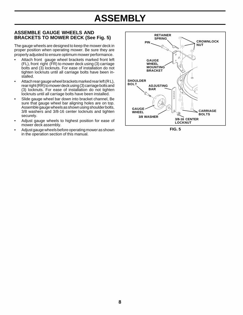
TO ATTACH NOSE ROLLER (See Fig. 4)• Position brackets, washers and nose roller between
deck mounting brackets as shown. Be sure to positionbrackets on correct side, as shown.
• Install hex bolts and locknuts as shown. Tightenhardware securely.
NOTE: Be sure tabs brackets are positioned in tab holes indeck brackets.
FIG. 4
"B" BRACKET TAB
WASHER
LOCKNUT
TABHOLE
NOSE ROLLER
"A"BRACKET TAB
HEXBOLT
TO DRIVE TRACTOR OFF SKID (See Opera-tion section, page 12, for location and func-tion of controls)
WARNING: Before starting, read, understand and followall instructions in the Operation section of this manual. Besure tractor is in a well-ventilated area. Be sure the area infront of tractor is clear of other people and objects.• Be sure all the above assembly steps have been
completed.• Check engine oil level and fill fuel tank with gasoline.• Place freewheel control in "transmission engaged" po-
sition.• Sit on seat in operating position, depress clutch/brake
pedal and set the parking brake.• Place motion control lever in neutral (N) position.• Press lift lever plunger and raise attachment lift lever to
its highest position.• Start the engine. After engine has started, move throttle
control to idle position.• Release parking brake.• Slowly move the motion control lever forward and slowly
drive tractor off skid.• Apply brake to stop tractor, set parking brake and place
motion control lever in neutral position.• Turn ignition key to "OFF" position.Continue with the instructions that follow.
ASSEMBLY
8
ASSEMBLY
FIG. 5
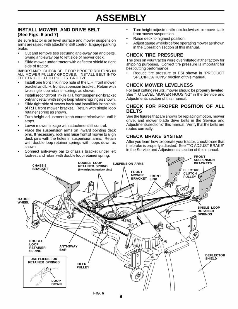
ASSEMBLE GAUGE WHEELS ANDBRACKETS TO MOWER DECK (See Fig. 5)
The gauge wheels are designed to keep the mower deck inproper position when operating mower. Be sure they areproperly adjusted to ensure optimum mower performance.• Attach front gauge wheel brackets marked front left
(FL), front right (FR) to mower deck using (3) carriagebolts and (3) locknuts. For ease of installation do nottighten locknuts until all carriage bolts have been in-stalled.
• Attach rear gauge wheel brackets marked rear left (R L),rear right (RR) to mower deck using (3) carriage bolts and(3) locknuts. For ease of installation do not tightenlocknuts until all carriage bolts have been installed.
• Slide gauge wheel bar down into bracket channel, Besure that gauge wheel bar aligning holes are on top.Assemble gauge wheels as shown using shoulder bolts,3/8 washers and 3/8-16 center locknuts and tightensecurely.
• Adjust gauge wheels to highest position for ease ofmower deck assembly.
• Adjust gauge wheels before operating mower as shownin the operation section of this manual.
SHOULDERBOLT
GAUGEWHEEL
3/8-16 CENTERLOCKNUT
GAUGEWHEELMOUNTINGBRACKET
3/8 WASHER
CARRIAGEBOLTS
CROWNLOCKNUT
ADJUSTINGBAR
PIN
RETAINERSPRING
9
ASSEMBLY• Turn height adjustment knob clockwise to remove slack
from mower suspension.• Raise deck to highest position.• Adjust gauge wheels before operating mower as shown
in the Operation section of this manual.
CHECK TIRE PRESSUREThe tires on your tractor were overinflated at the factory forshipping purposes. Correct tire pressure is important forbest cutting performance.• Reduce tire pressure to PSI shown in “PRODUCT
SPECIFICATIONS” section of this manual.
CHECK MOWER LEVELNESSFor best cutting results, mower should be properly leveled.See “TO LEVEL MOWER HOUSING” in the Service andAdjustments section of this manual.
CHECK FOR PROPER POSITION OF ALLBELTSSee the figures that are shown for replacing motion, mowerdrive, and mower blade drive belts in the Service andAdjustments section of this manual. Verify that the belts arerouted correctly.
CHECK BRAKE SYSTEMAfter you learn how to operate your tractor, check to see thatthe brake is properly adjusted. See “TO ADJUST BRAKE”in the Service and Adjustments section of this manual.
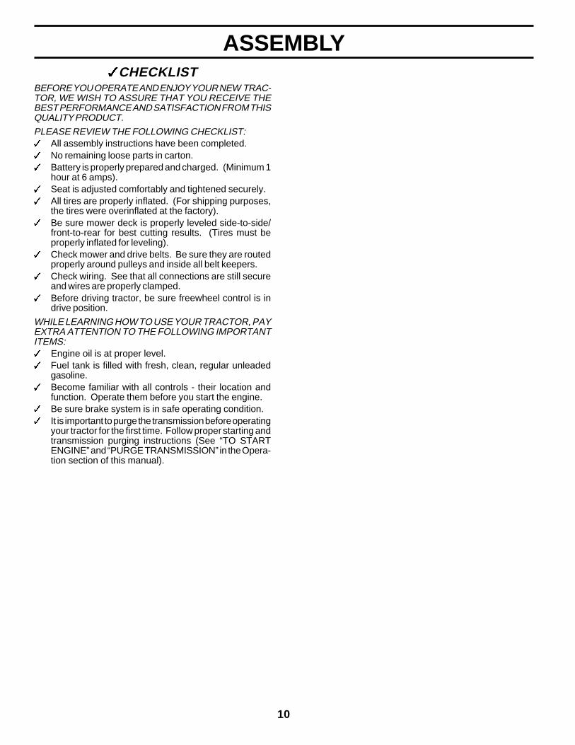
INSTALL MOWER AND DRIVE BELT(See Figs. 6 and 7)Be sure tractor is on level surface and mower suspensionarms are raised with attachment lift control. Engage parkingbrake.• Cut and remove ties securing anti-sway bar and belts.
Swing anti-sway bar to left side of mower deck.• Slide mower under tractor with deflector shield to right
side of tractor.IMPORTANT: CHECK BELT FOR PROPER ROUTING INALL MOWER PULLEY GROOVES. INSTALL BELT INTOELECTRIC CLUTCH PULLEY GROOVE.• Install one front link in top hole of the L.H. front mower
bracket and L.H. front suspension bracket. Retain withtwo single loop retainer springs as shown.
• Install second front link in R.H. front suspension bracketonly and retain with single loop retainer spring as shown.
• Slide right side of mower back and install link in top holeof R.H. front mower bracket. Retain with single loopretainer spring as shown.
• Turn height adjustment knob counterclockwise until itstops.
• Lower mower linkage with attachment lift control.• Place the suspension arms on inward pointing deck
pins. If necessary, rock and raise front of mower to aligndeck pins with the holes in suspension arms. Retainwith double loop retainer springs with loops down asshown.
• Connect anti-sway bar to chassis bracket under leftfootrest and retain with double loop retainer spring.
CHASSISBRACKET
ANTI-SWAYBAR
DOUBLELOOPRETAINERSPRING
GAUGEWHEEL
IDLERPULLEY
SUSPENSION ARMS
FRONTMOWERBRACKET
DEFLECTORSHIELD
SINGLE LOOPRETAINERSPRINGS
DOUBLE LOOPRETAINER SPRING(Inward pointing deck pins) ELECTRIC
CLUTCHPULLEY
FRONTSUSPENSIONBRACKETS
FRONTLINK
USE PLIERS FORRETAINER SPRINGS
FIG. 6
LOOPDOWN
10
ASSEMBLY3CHECKLIST
BEFORE YOU OPERATE AND ENJOY YOUR NEW TRAC-TOR, WE WISH TO ASSURE THAT YOU RECEIVE THEBEST PERFORMANCE AND SATISFACTION FROM THISQUALITY PRODUCT.PLEASE REVIEW THE FOLLOWING CHECKLIST:3 All assembly instructions have been completed.3 No remaining loose parts in carton.3 Battery is properly prepared and charged. (Minimum 1
hour at 6 amps).3 Seat is adjusted comfortably and tightened securely.3 All tires are properly inflated. (For shipping purposes,
the tires were overinflated at the factory).3 Be sure mower deck is properly leveled side-to-side/
front-to-rear for best cutting results. (Tires must beproperly inflated for leveling).
3 Check mower and drive belts. Be sure they are routedproperly around pulleys and inside all belt keepers.
3 Check wiring. See that all connections are still secureand wires are properly clamped.
3 Before driving tractor, be sure freewheel control is indrive position.
WHILE LEARNING HOW TO USE YOUR TRACTOR, PAYEXTRA ATTENTION TO THE FOLLOWING IMPORTANTITEMS:3 Engine oil is at proper level.3 Fuel tank is filled with fresh, clean, regular unleaded
gasoline.3 Become familiar with all controls - their location and
function. Operate them before you start the engine.3 Be sure brake system is in safe operating condition.3 It is important to purge the transmission before operating
your tractor for the first time. Follow proper starting andtransmission purging instructions (See “TO STARTENGINE” and “PURGE TRANSMISSION” in the Opera-tion section of this manual).

11
OPERATIONThese symbols may appear on your tractor or in literature supplied with the product. Learn and understand their meaning.
BATTERY CAUTION ORWARNING
REVERSE FORWARD FAST SLOW
ENGINE ON ENGINE OFF OIL PRESSURE LIGHTS ON
FUEL CHOKE MOWER HEIGHT PARKING BRAKELOCKED
UNLOCKED
REVERSE NEUTRAL HIGH LOWATTACHMENTCLUTCH ENGAGED
MOWER LIFT
DANGER, KEEP HANDS AND FEET AWAY FREE WHEEL
(Automatic Models only)
OVER TEMPLIGHT
PARKING BRAKE
IGNITIONATTACHMENT
CLUTCH DISENGAGED
P
KEEP AREA CLEAR SLOPE HAZARDS
15 15 15
(SEE SAFETY RULES SECTION)
12
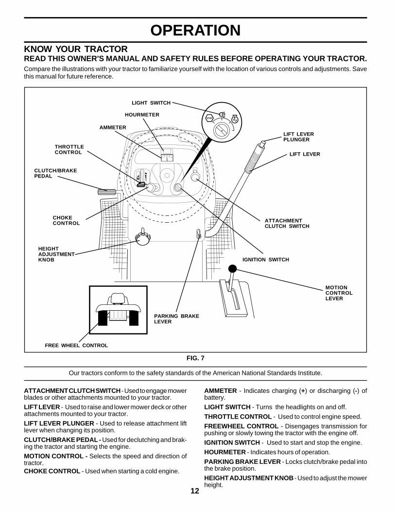
OPERATIONKNOW YOUR TRACTORREAD THIS OWNER'S MANUAL AND SAFETY RULES BEFORE OPERATING YOUR TRACTOR.Compare the illustrations with your tractor to familiarize yourself with the location of various controls and adjustments. Savethis manual for future reference.
FIG. 7
THROTTLECONTROL
CHOKECONTROL
ATTACHMENT CLUTCH SWITCH - Used to engage mowerblades or other attachments mounted to your tractor.
LIFT LEVER - Used to raise and lower mower deck or otherattachments mounted to your tractor.
LIFT LEVER PLUNGER - Used to release attachment liftlever when changing its position.
CLUTCH/BRAKE PEDAL - Used for declutching and brak-ing the tractor and starting the engine.
MOTION CONTROL - Selects the speed and direction oftractor.CHOKE CONTROL - Used when starting a cold engine.
AMMETER - Indicates charging (+) or discharging (-) ofbattery.
LIGHT SWITCH - Turns the headlights on and off.
THROTTLE CONTROL - Used to control engine speed.
FREEWHEEL CONTROL - Disengages transmission forpushing or slowly towing the tractor with the engine off.
IGNITION SWITCH - Used to start and stop the engine.
HOURMETER - Indicates hours of operation.
PARKING BRAKE LEVER - Locks clutch/brake pedal intothe brake position.
HEIGHT ADJUSTMENT KNOB - Used to adjust the mowerheight.
Our tractors conform to the safety standards of the American National Standards Institute.
MOTIONCONTROLLEVER
PARKING BRAKELEVER
HEIGHTADJUSTMENTKNOB IGNITION SWITCH
CLUTCH/BRAKEPEDAL
LIFT LEVER
ATTACHMENTCLUTCH SWITCH
FREE WHEEL CONTROL
LIFT LEVERPLUNGER
LIGHT SWITCH
HOURMETER
AMMETER
13
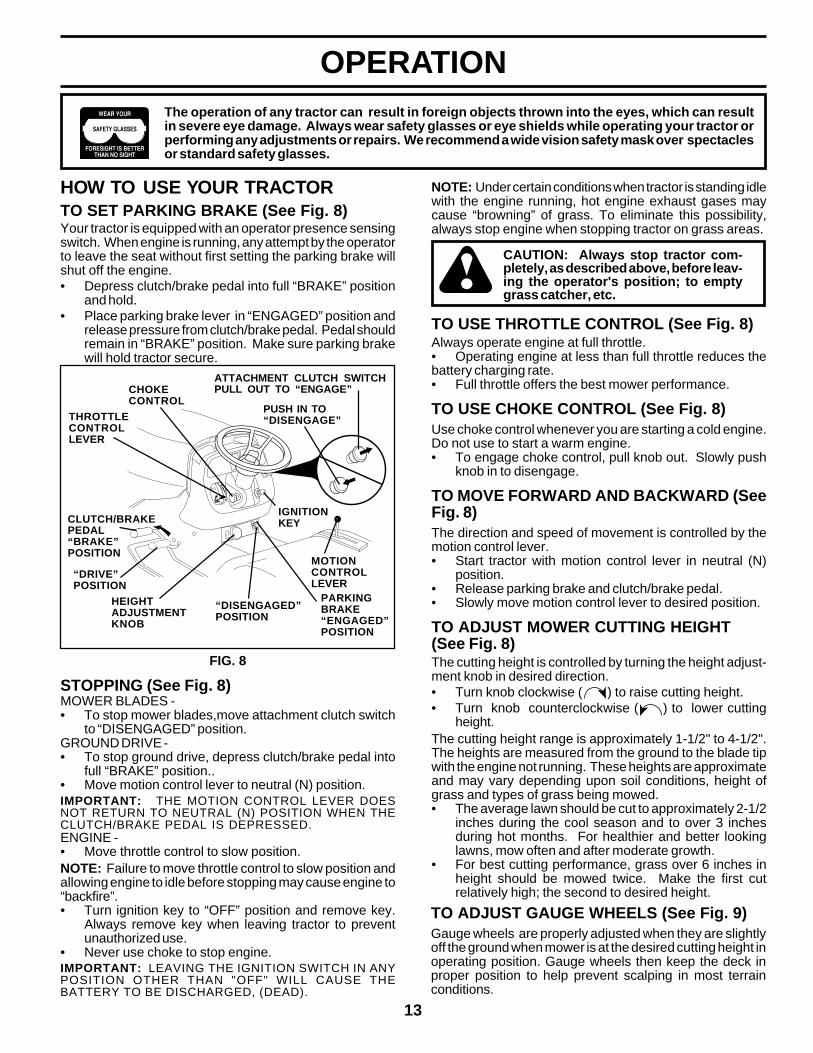
OPERATION
HOW TO USE YOUR TRACTORTO SET PARKING BRAKE (See Fig. 8)Your tractor is equipped with an operator presence sensingswitch. When engine is running, any attempt by the operatorto leave the seat without first setting the parking brake willshut off the engine.• Depress clutch/brake pedal into full “BRAKE” position
and hold.• Place parking brake lever in “ENGAGED” position and
release pressure from clutch/brake pedal. Pedal shouldremain in “BRAKE” position. Make sure parking brakewill hold tractor secure.
The operation of any tractor can result in foreign objects thrown into the eyes, which can resultin severe eye damage. Always wear safety glasses or eye shields while operating your tractor orperforming any adjustments or repairs. We recommend a wide vision safety mask over spectaclesor standard safety glasses.
NOTE: Under certain conditions when tractor is standing idlewith the engine running, hot engine exhaust gases maycause “browning” of grass. To eliminate this possibility,always stop engine when stopping tractor on grass areas.
CAUTION: Always stop tractor com-pletely, as described above, before leav-ing the operator's position; to emptygrass catcher, etc.
TO USE THROTTLE CONTROL (See Fig. 8)Always operate engine at full throttle.• Operating engine at less than full throttle reduces thebattery charging rate.• Full throttle offers the best mower performance.
TO USE CHOKE CONTROL (See Fig. 8)Use choke control whenever you are starting a cold engine.Do not use to start a warm engine.• To engage choke control, pull knob out. Slowly push
knob in to disengage.
TO MOVE FORWARD AND BACKWARD (SeeFig. 8)The direction and speed of movement is controlled by themotion control lever.• Start tractor with motion control lever in neutral (N)
position.• Release parking brake and clutch/brake pedal.• Slowly move motion control lever to desired position.
TO ADJUST MOWER CUTTING HEIGHT(See Fig. 8)The cutting height is controlled by turning the height adjust-ment knob in desired direction.• Turn knob clockwise ( ) to raise cutting height.• Turn knob counterclockwise ( ) to lower cutting
height.The cutting height range is approximately 1-1/2" to 4-1/2".The heights are measured from the ground to the blade tipwith the engine not running. These heights are approximateand may vary depending upon soil conditions, height ofgrass and types of grass being mowed.• The average lawn should be cut to approximately 2-1/2
inches during the cool season and to over 3 inchesduring hot months. For healthier and better lookinglawns, mow often and after moderate growth.
• For best cutting performance, grass over 6 inches inheight should be mowed twice. Make the first cutrelatively high; the second to desired height.
FIG. 8
“DRIVE”POSITION
PARKINGBRAKE“ENGAGED”POSITION
IGNITIONKEY
HEIGHTADJUSTMENTKNOB
“DISENGAGED”POSITION
STOPPING (See Fig. 8)MOWER BLADES -• To stop mower blades,move attachment clutch switch
to “DISENGAGED” position.GROUND DRIVE -• To stop ground drive, depress clutch/brake pedal into
full “BRAKE” position..• Move motion control lever to neutral (N) position.IMPORTANT: THE MOTION CONTROL LEVER DOESNOT RETURN TO NEUTRAL (N) POSITION WHEN THECLUTCH/BRAKE PEDAL IS DEPRESSED.ENGINE -• Move throttle control to slow position.NOTE: Failure to move throttle control to slow position andallowing engine to idle before stopping may cause engine to“backfire”.• Turn ignition key to “OFF” position and remove key.
Always remove key when leaving tractor to preventunauthorized use.
• Never use choke to stop engine.IMPORTANT: LEAVING THE IGNITION SWITCH IN ANYPOSITION OTHER THAN "OFF" WILL CAUSE THEBATTERY TO BE DISCHARGED, (DEAD).
ATTACHMENT CLUTCH SWITCHPULL OUT TO “ENGAGE”
PUSH IN TO“DISENGAGE”
MOTIONCONTROLLEVER
CLUTCH/BRAKEPEDAL“BRAKE”POSITION
CHOKECONTROL
THROTTLECONTROLLEVER
TO ADJUST GAUGE WHEELS (See Fig. 9)Gauge wheels are properly adjusted when they are slightlyoff the ground when mower is at the desired cutting height inoperating position. Gauge wheels then keep the deck inproper position to help prevent scalping in most terrainconditions.
14
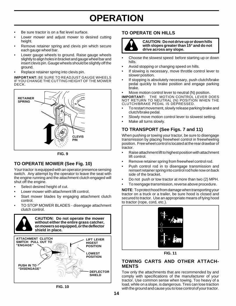
OPERATIONTO OPERATE ON HILLS
CAUTION: Do not drive up or down hillswith slopes greater than 15° and do notdrive across any slope.
• Choose the slowest speed before starting up or downhills.
• Avoid stopping or changing speed on hills.• If slowing is necessary, move throttle control lever to
slower position.• If stopping is absolutely necessary, push clutch/brake
pedal quickly to brake position and engage parkingbrake.
• Move motion control lever to neutral (N) position.IMPORTANT: THE MOTION CONTROL LEVER DOESNOT RETURN TO NEUTRAL (N) POSITION WHEN THECLUTCH/BRAKE PEDAL IS DEPRESSED.• To restart movement, slowly release parking brake and
clutch/brake pedal.• Slowly move motion control lever to slowest setting.• Make all turns slowly.
FIG. 11
TO OPERATE MOWER (See Fig. 10)Your tractor is equipped with an operator presence sensingswitch. Any attempt by the operator to leave the seat withthe engine running and the attachment clutch engaged willshut off the engine.• Select desired height of cut.• Lower mower with attachment lift control.• Start mower blades by engaging attachment clutch
control.• TO STOP MOWER BLADES - disengage attachment
clutch control.
CAUTION: Do not operate the mowerwithout either the entire grass catcher,on mowers so equipped, or the deflectorshield in place.
LOWESTPOSITION
DEFLECTORSHIELD
FIG. 10
FIG. 9
TO TRANSPORT (See Figs. 7 and 11)When pushing or towing your tractor, be sure to disengagetransmission by placing freewheel control in freewheelingposition. Free wheel control is located at the rear drawbar oftractor.• Raise attachment lift to highest position with attachment
lift control.• Remove retainer spring from freewheel control rod.• Push control rod in to disengage transmission and
reinsert retainer spring into control rod hole now on backside of the bracket.
• Do not push or tow tractor at more than two (2) MPH.• To reengage transmission, reverse above procedure.
NOTE: To protect hood from damage when transporting yourtractor on a truck or a trailer, be sure hood is closed andsecured to tractor. Use an appropriate means of tying hoodto tractor (rope, cord, etc.).
• Be sure tractor is on a flat level surface.• Lower mower and adjust mower to desired cutting
height.• Remove retainer spring and clevis pin which secure
each gauge wheel bar.• Lower gauge wheels to ground. Raise gauge wheels
slightly to align holes in bracket and gauge wheel bar andinsert clevis pin. Gauge wheels should be slightly off theground.
• Replace retainer spring into clevis pin.IMPORTANT: BE SURE TO READJUST GAUGE WHEELSIF YOU CHANGE THE CUTTING HEIGHT OF THE MOWERDECK.
CLEVISPIN
RETAINERSPRING
TOWING CARTS AND OTHER ATTACH-MENTSTow only the attachments that are recommended by andcomply with specifications of the manufacturer of yourtractor. Use common sense when towing. Too heavy of aload, while on a slope, is dangerous. Tires can lose tractionwith the ground and cause you to lose control of your tractor.
LIFT LEVERHIGESTPOSITION
ATTACHMENT CLUTCHSWITCH PULL OUT TO“ENGAGE”
PUSH IN TO“DISENGAGE”
15
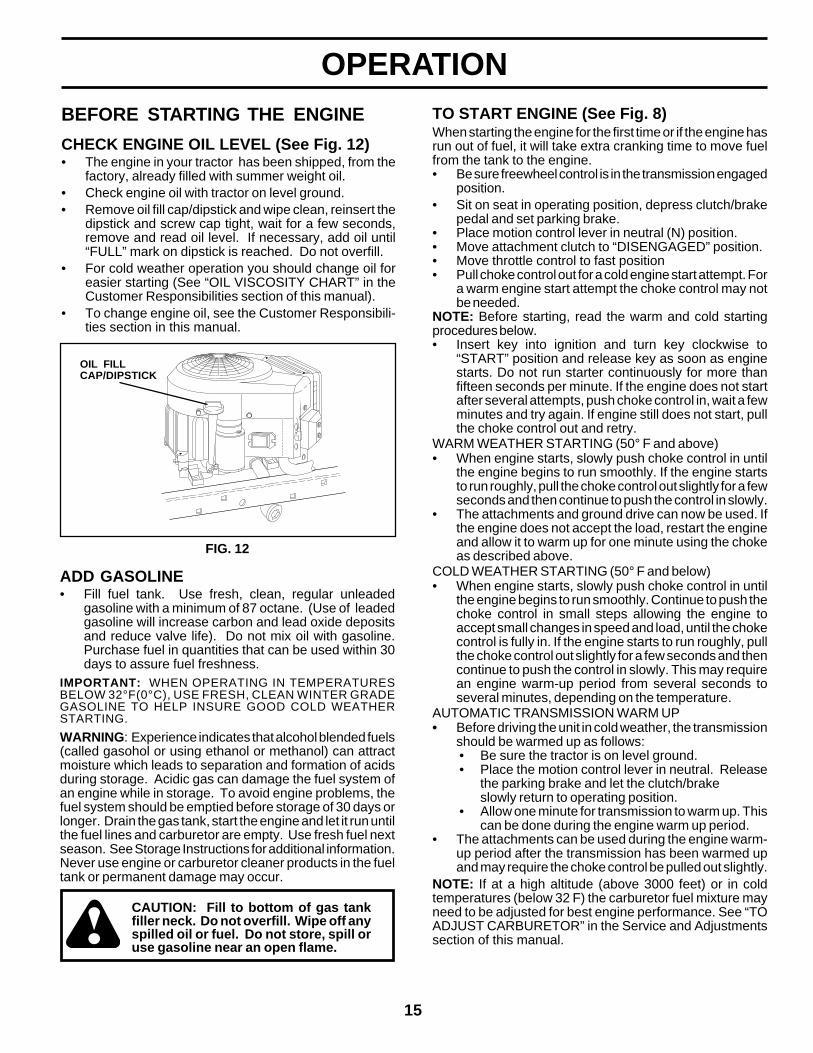
OPERATIONBEFORE STARTING THE ENGINE
CHECK ENGINE OIL LEVEL (See Fig. 12)• The engine in your tractor has been shipped, from the
factory, already filled with summer weight oil.• Check engine oil with tractor on level ground.• Remove oil fill cap/dipstick and wipe clean, reinsert the
dipstick and screw cap tight, wait for a few seconds,remove and read oil level. If necessary, add oil until“FULL” mark on dipstick is reached. Do not overfill.
• For cold weather operation you should change oil foreasier starting (See “OIL VISCOSITY CHART” in theCustomer Responsibilities section of this manual).
• To change engine oil, see the Customer Responsibili-ties section in this manual.
OIL FILLCAP/DIPSTICK
FIG. 12
ADD GASOLINE• Fill fuel tank. Use fresh, clean, regular unleaded
gasoline with a minimum of 87 octane. (Use of leadedgasoline will increase carbon and lead oxide depositsand reduce valve life). Do not mix oil with gasoline.Purchase fuel in quantities that can be used within 30days to assure fuel freshness.
IMPORTANT: WHEN OPERATING IN TEMPERATURESBELOW 32°F(0°C), USE FRESH, CLEAN WINTER GRADEGASOLINE TO HELP INSURE GOOD COLD WEATHERSTARTING.
WARNING: Experience indicates that alcohol blended fuels(called gasohol or using ethanol or methanol) can attractmoisture which leads to separation and formation of acidsduring storage. Acidic gas can damage the fuel system ofan engine while in storage. To avoid engine problems, thefuel system should be emptied before storage of 30 days orlonger. Drain the gas tank, start the engine and let it run untilthe fuel lines and carburetor are empty. Use fresh fuel nextseason. See Storage Instructions for additional information.Never use engine or carburetor cleaner products in the fueltank or permanent damage may occur.
CAUTION: Fill to bottom of gas tankfiller neck. Do not overfill. Wipe off anyspilled oil or fuel. Do not store, spill oruse gasoline near an open flame.
TO START ENGINE (See Fig. 8)When starting the engine for the first time or if the engine hasrun out of fuel, it will take extra cranking time to move fuelfrom the tank to the engine.• Be sure freewheel control is in the transmission engaged
position.• Sit on seat in operating position, depress clutch/brake
pedal and set parking brake.• Place motion control lever in neutral (N) position.• Move attachment clutch to “DISENGAGED” position.• Move throttle control to fast position• Pull choke control out for a cold engine start attempt. For
a warm engine start attempt the choke control may notbe needed.
NOTE: Before starting, read the warm and cold startingprocedures below.• Insert key into ignition and turn key clockwise to
“START” position and release key as soon as enginestarts. Do not run starter continuously for more thanfifteen seconds per minute. If the engine does not startafter several attempts, push choke control in, wait a fewminutes and try again. If engine still does not start, pullthe choke control out and retry.
WARM WEATHER STARTING (50° F and above)• When engine starts, slowly push choke control in until
the engine begins to run smoothly. If the engine startsto run roughly, pull the choke control out slightly for a fewseconds and then continue to push the control in slowly.
• The attachments and ground drive can now be used. Ifthe engine does not accept the load, restart the engineand allow it to warm up for one minute using the chokeas described above.
COLD WEATHER STARTING (50° F and below)• When engine starts, slowly push choke control in until
the engine begins to run smoothly. Continue to push thechoke control in small steps allowing the engine toaccept small changes in speed and load, until the chokecontrol is fully in. If the engine starts to run roughly, pullthe choke control out slightly for a few seconds and thencontinue to push the control in slowly. This may requirean engine warm-up period from several seconds toseveral minutes, depending on the temperature.
AUTOMATIC TRANSMISSION WARM UP• Before driving the unit in cold weather, the transmission
should be warmed up as follows:• Be sure the tractor is on level ground.• Place the motion control lever in neutral. Release
the parking brake and let the clutch/brakeslowly return to operating position.
• Allow one minute for transmission to warm up. Thiscan be done during the engine warm up period.
• The attachments can be used during the engine warm-up period after the transmission has been warmed upand may require the choke control be pulled out slightly.
NOTE: If at a high altitude (above 3000 feet) or in coldtemperatures (below 32 F) the carburetor fuel mixture mayneed to be adjusted for best engine performance. See “TOADJUST CARBURETOR” in the Service and Adjustmentssection of this manual.

16
OPERATIONPURGE TRANSMISSION
CAUTION: Never engage or disengagefreewheel lever while the engine is run-ning.
To ensure proper operation and performance, it is recom-mended that the transmission be purged before operatingtractor for the first time. This procedure will remove anytrapped air inside the transmission which may have devel-oped during shipping of your tractor.IMPORTANT: SHOULD YOUR TRANSMISSION REQUIREREMOVAL FOR SERVICE OR REPLACEMENT, ITSHOULD BE PURGED AFTER REINSTALLATION BEFOREOPERATING THE TRACTOR.• Place tractor safely on level surface with engine off and
parking brake set.• Disengage transmission by placing freewheel control in
freewheeling position (See “TO TRANSPORT” in thissection of this manual).
• Sitting in the tractor seat, start engine. After the engineis running, move throttle control to slow position. Withmotion control lever in neutral (N) position, slowlydisengage clutch/brake pedal.
• Move motion control lever to full forward position andhold for five (5) seconds. Move lever to full reverseposition and hold for five (5) seconds. Repeat thisprocedure three (3) times.
NOTE: During this procedure there will be no movement ofdrive wheels. The air is being removed from hydraulic drivesystem.• Move motion control lever to neutral (N) position. Shut
off engine and set parking brake.• Engage transmission by placing freewheel control in
driving position (See “TO TRANSPORT” in this sectionof this manual).
• Sitting in the tractor seat, start engine. After the engineis running, move throttle control to half (1/2) speed. Withmotion control lever in neutral (N) position, slowlydisengage clutch/brake pedal.
• Slowly move motion control lever forward. After thetractor moves approximately five (5) feet, slowly movemotion control lever to reverse position. After the tractormoves approximately five (5) feet, return the motioncontrol lever to the neutral (N) position. Repeat thisprocedure with the motion control lever three (3) times.
• Your tractor is now purged and ready for normal opera-tion.
MOWING TIPS• Tire chains cannot be used when the mower housing is
attached to tractor.• Mower should be properly leveled for best mowing
performance. See “TO LEVEL MOWER HOUSING” inthe Service and Adjustments section of this manual.
• The left hand side of mower should be used for trimming.• Drive so that clippings are discharged onto the area that
has been cut. Have the cut area to the right of the tractor.This will result in a more even distribution of clippingsand more uniform cutting.
• When mowing large areas, start by turning to the right sothat clippings will discharge away from shrubs, fences,driveways, etc. After one or two rounds, mow in theopposite direction making left hand turns until finished(See Fig. 13).
• If grass is extremely tall, it should be mowed twice toreduce load and possible fire hazard from dried clip-pings. Make first cut relatively high; the second to thedesired height.
• Do not mow grass when it is wet. Wet grass will plugmower and leave undesirable clumps. Allow grass to drybefore mowing.
• Always operate engine at full throttle when mowingto assure better mowing performance and proper dis-charge of material. Regulate ground speed by selectinga low enough gear to give the mower cutting perfor-mance as well as the quality of cut desired.
• When operating attachments, select a ground speedthat will suit the terrain and give best performance of theattachment being used.
FIG. 13
17
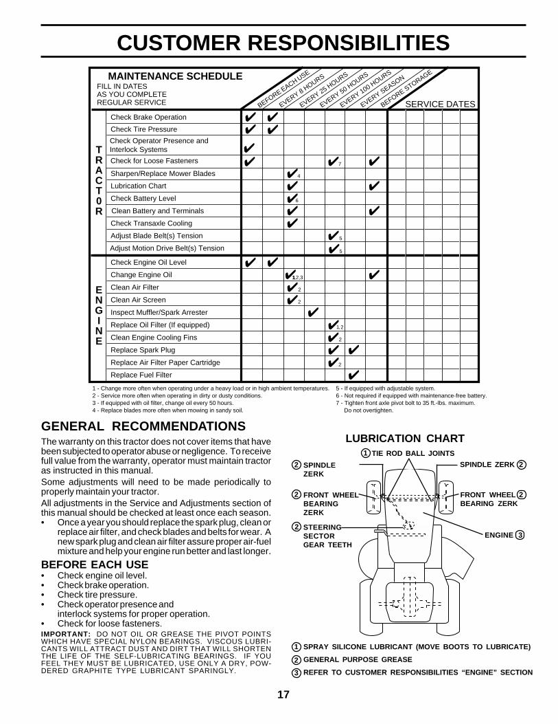
BEFORE EACH USE
TRACT0R
Adjust Motion Drive Belt(s) Tension
Inspect Muffler/Spark Arrester
Lubrication Chart
Check Brake Operation
Clean Air Filter
Change Engine Oil
Replace Air Filter Paper Cartridge
Replace Spark Plug
Check Battery Level
Check Tire Pressure
Clean Battery and Terminals
FILL IN DATESAS YOU COMPLETEREGULAR SERVICE
MAINTENANCE SCHEDULE
EVERY 8 HOURS
EVERY 25 HOURS
EVERY 50 HOURS
EVERY 100 HOURS
EVERY SEASON
SERVICE DATES
Check for Loose Fasteners
BEFORE STORAGE
Check Engine Oil Level
Clean Engine Cooling Fins
Sharpen/Replace Mower Blades
Check Operator Presence andInterlock Systems
Clean Air Screen
1 - Change more often when operating under a heavy load or in high ambient temperatures.2 - Service more often when operating in dirty or dusty conditions.3 - If equipped with oil filter, change oil every 50 hours.4 - Replace blades more often when mowing in sandy soil.
ENGINE
Replace Oil Filter (If equipped)
Check Transaxle Cooling
Adjust Blade Belt(s) Tension
Replace Fuel Filter
1
4
2
2
2
2
5 - If equipped with adjustable system.6 - Not required if equipped with maintenance-free battery.7 - Tighten front axle pivot bolt to 35 ft.-lbs. maximum. Do not overtighten.
1,
12,3,
2
5
5
6
7
GENERAL RECOMMENDATIONSThe warranty on this tractor does not cover items that havebeen subjected to operator abuse or negligence. To receivefull value from the warranty, operator must maintain tractoras instructed in this manual.Some adjustments will need to be made periodically toproperly maintain your tractor.All adjustments in the Service and Adjustments section ofthis manual should be checked at least once each season.• Once a year you should replace the spark plug, clean or
replace air filter, and check blades and belts for wear. Anew spark plug and clean air filter assure proper air-fuelmixture and help your engine run better and last longer.
BEFORE EACH USE• Check engine oil level.• Check brake operation.• Check tire pressure.• Check operator presence and
interlock systems for proper operation.• Check for loose fasteners.
TIE ROD BALL JOINTS1
FRONT WHEELBEARING ZERK
2
ENGINE
SPINDLEZERK
FRONT WHEELBEARINGZERK
2
2 2
3
SPINDLE ZERK
STEERINGSECTORGEAR TEETH
2
LUBRICATION CHART
SPRAY SILICONE LUBRICANT (MOVE BOOTS TO LUBRICATE)
GENERAL PURPOSE GREASE
REFER TO CUSTOMER RESPONSIBILITIES “ENGINE” SECTION
IMPORTANT: DO NOT OIL OR GREASE THE PIVOT POINTSWHICH HAVE SPECIAL NYLON BEARINGS. VISCOUS LUBRI-CANTS WILL ATTRACT DUST AND DIRT THAT WILL SHORTENTHE LIFE OF THE SELF-LUBRICATING BEARINGS. IF YOUFEEL THEY MUST BE LUBRICATED, USE ONLY A DRY, POW-DERED GRAPHITE TYPE LUBRICANT SPARINGLY.
2
1
3
CUSTOMER RESPONSIBILITIES
18
CUSTOMER RESPONSIBILITIES
FIG. 14
MANDRELASSEMBLY
BLADE
TRAILING EDGE UP
FLATWASHER
LOCKWASHER
HEX BOLT(GRADE 8)*
*A GRADE 8 HEAT TREATED BOLT CAN BEIDENTIFIED BY SIX LINES ON THE BOLT HEAD.
CENTERHOLE
STAR
TRACTORAlways observe safety rules when performing any mainte-nance.
BRAKE OPERATIONIf tractor requires more than six (6) feet stopping distance athigh speed in highest gear, then brake must be adjusted.(See “TO ADJUST BRAKE” in the Service and Adjustmentssection of this manual).
TIRES• Maintain proper air pressure in all tires (See “PRODUCT
SPECIFICATIONS” section of this manual).• Keep tires free of gasoline, oil, or insect control chemi-
cals which can harm rubber.• Avoid stumps, stones, deep ruts, sharp objects and
other hazards that may cause tire damage.NOTE: To seal tire punctures and prevent flat tires due toslow leaks, tire sealant may be purchased from your localparts dealer. Tire sealant also prevents tire dry rot andcorrosion.
OPERATOR PRESENCE SYSTEMBe sure operator presence and interlock systems are work-ing properly. If your tractor does not function as described,repair the problem immediately.• The engine should not start unless the clutch/brake
pedal is fully depressed and attachement clutch controlis in the disengaged position.
• When the engine is running, any attempt by the operatorto leave the seat without first setting the parking brakeshould shut off the engine.
• When the engine is running and the attachment clutch isengaged, any attempt by the operator to leave the seatshould shut off the engine.
• The attachment clutch should never operate unless theoperator is in the seat..
BLADE CAREFor best results mower blades must be kept sharp. Replacebent or damaged blades.
BLADE REMOVAL (See Fig. 14)• Raise mower to highest position to allow access to
blades.• Remove hex bolt, lock washer and flat washer securing
blade.• Install new or resharpened blade with trailing edge up
towards deck as shown.
IMPORTANT: TO ENSURE PROPER ASSEMBLY, CENTERHOLE IN BLADE MUST ALIGN WITH STAR ON MANDRELASSEMBLY.• Reassemble hex bolt, lock washer and flat washer in
exact order as shown.• Tighten bolt securely (27-35 Ft. Lbs. torque).IMPORTANT: BLADE BOLT IS GRADE 8 HEAT TREATED.
TO SHARPEN BLADE (See Fig. 15)NOTE: We do not recommend sharpening blade - but if youdo, be sure the blade is balanced.Care should be taken to keep the blade balanced. Anunbalanced blade will cause excessive vibration and even-tual damage to mower and engine.• The blade can be sharpened with a file or on a grinding
wheel. Do not attempt to sharpen while on the mower.• To check blade balance, you will need a 5/8" diameter
steel bolt, pin, or a cone balancer. (When using a conebalancer, follow the instructions supplied with balancer).
NOTE: Do not use a nail for balancing blade. The lobes ofthe center hole may appear to be centered, but are not.• Slide blade on to an unthreaded portion of the steel bolt
or pin and hold the bolt or pin parallel with the ground. Ifblade is balanced, it should remain in a horizontalposition. If either end of the blade moves downward,sharpen the heavy end until the blade is balanced.
5/8" BOLTOR PIN
BLADE
CENTER HOLE
FIG. 15BATTERYYour tractor has a battery charging system which is suffi-cient for normal use. However, periodic charging of thebattery with an automotive charger will extend its life.• Keep battery and terminals clean.• Keep battery bolts tight.• Keep small vent holes open.• Recharge at 6-10 amperes for 1 hour.
NOTE: The original equipment battery on your tractor ismaintenance free. Do not attempt to open or remove capsor covers. Adding or checking level of electrolyte is notnecessary.
TO CLEAN BATTERY AND TERMINALSCorrosion and dirt on the battery and terminals can causethe battery to “leak” power.• Remove terminal guard.• Disconnect BLACK battery cable first then RED
battery cable and remove battery from tractor.• Rinse the battery with plain water and dry.• Clean terminals and battery cable ends with wire brush
until bright.• Coat terminals with grease or petroleum jelly.• Reinstall battery (See “REPLACING BATTERY" in the
SERVICE AND ADJUSTMENTS section of this manual).
19
CUSTOMER RESPONSIBILITIESV-BELTSCheck V-belts for deterioration and wear after 100 hours ofoperation and replace if necessary. The belts are notadjustable. Replace belts if they begin to slip from wear.
TRANSAXLE COOLINGThe transmission fan and cooling fins should be kept cleanto assure proper cooling.
Do not attempt to clean fan or transmission while engine isrunning or while the transmission is hot. To prevent possibledamage to seals, do not use high pressure water or steamto clean transaxle.• Inspect cooling fan to be sure fan blades are intact and
clean.• Inspect cooling fins for dirt, grass clippings and other
materials. To prevent damage to seals, do not usecompressed air or high pressure sprayer to clean coolingfins.
TRANSAXLE PUMP FLUIDThe transaxle was sealed at the factory and fluid mainte-nance is not required for the life of the transaxle. Should thetransaxle ever leak or require servicing, contact your nearestauthorized service center/department.
CLEAN AIR SCREENAir screen must be kept free of dirt and chaff to preventengine damage from overheating. Clean with a wire brush orcompressed air to remove dirt and stubborn dried gum fibers.
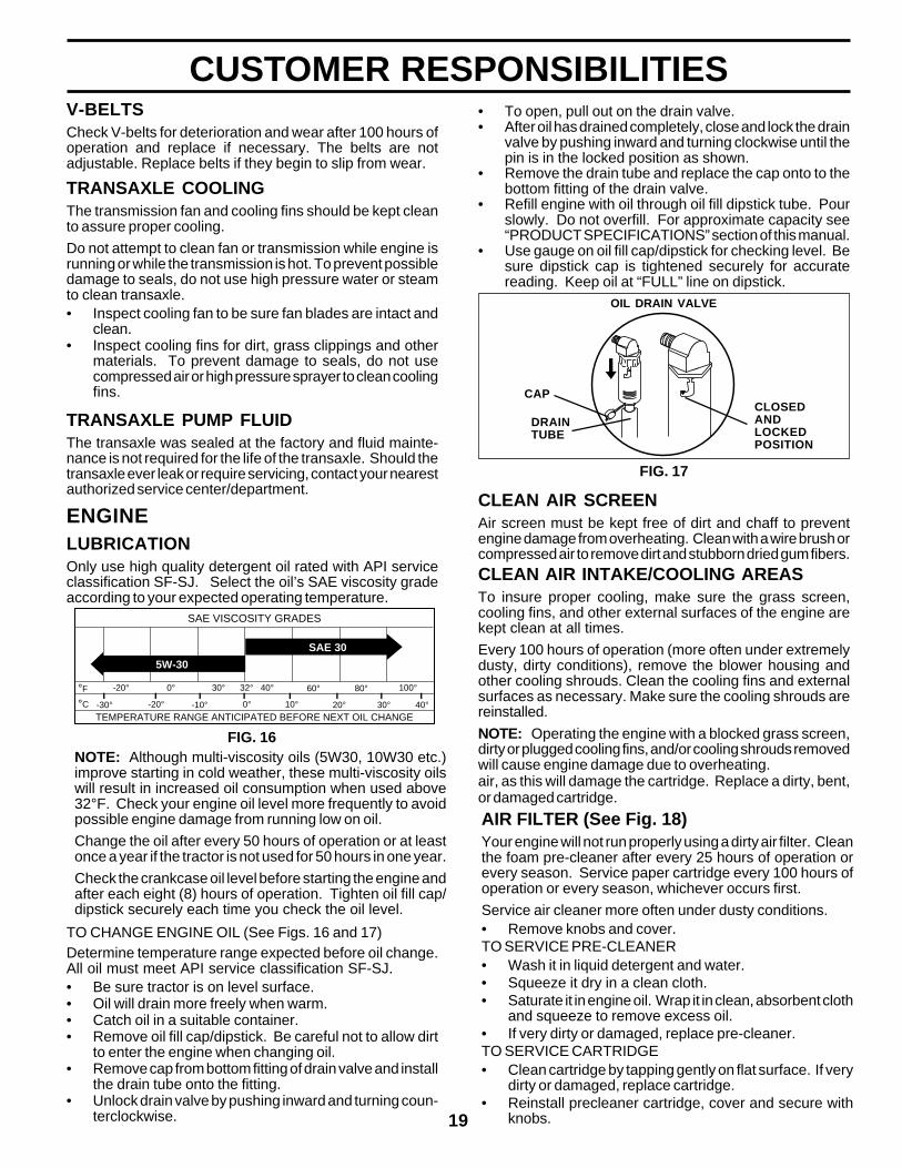
ENGINELUBRICATIONOnly use high quality detergent oil rated with API serviceclassification SF-SJ. Select the oil’s SAE viscosity gradeaccording to your expected operating temperature.
CLEAN AIR INTAKE/COOLING AREASTo insure proper cooling, make sure the grass screen,cooling fins, and other external surfaces of the engine arekept clean at all times.
Every 100 hours of operation (more often under extremelydusty, dirty conditions), remove the blower housing andother cooling shrouds. Clean the cooling fins and externalsurfaces as necessary. Make sure the cooling shrouds arereinstalled.
NOTE: Operating the engine with a blocked grass screen,dirty or plugged cooling fins, and/or cooling shrouds removedwill cause engine damage due to overheating.air, as this will damage the cartridge. Replace a dirty, bent,or damaged cartridge.
TO CHANGE ENGINE OIL (See Figs. 16 and 17)Determine temperature range expected before oil change.All oil must meet API service classification SF-SJ.• Be sure tractor is on level surface.• Oil will drain more freely when warm.• Catch oil in a suitable container.• Remove oil fill cap/dipstick. Be careful not to allow dirt
to enter the engine when changing oil.• Remove cap from bottom fitting of drain valve and install
the drain tube onto the fitting.• Unlock drain valve by pushing inward and turning coun-
terclockwise.
• To open, pull out on the drain valve.• After oil has drained completely, close and lock the drain
valve by pushing inward and turning clockwise until thepin is in the locked position as shown.
• Remove the drain tube and replace the cap onto to thebottom fitting of the drain valve.
• Refill engine with oil through oil fill dipstick tube. Pourslowly. Do not overfill. For approximate capacity see“PRODUCT SPECIFICATIONS” section of this manual.
• Use gauge on oil fill cap/dipstick for checking level. Besure dipstick cap is tightened securely for accuratereading. Keep oil at “FULL” line on dipstick.
AIR FILTER (See Fig. 18)Your engine will not run properly using a dirty air filter. Cleanthe foam pre-cleaner after every 25 hours of operation orevery season. Service paper cartridge every 100 hours ofoperation or every season, whichever occurs first.
Service air cleaner more often under dusty conditions.• Remove knobs and cover.TO SERVICE PRE-CLEANER• Wash it in liquid detergent and water.• Squeeze it dry in a clean cloth.• Saturate it in engine oil. Wrap it in clean, absorbent cloth
and squeeze to remove excess oil.• If very dirty or damaged, replace pre-cleaner.TO SERVICE CARTRIDGE• Clean cartridge by tapping gently on flat surface. If very
dirty or damaged, replace cartridge.• Reinstall precleaner cartridge, cover and secure with
knobs.
FIG. 16NOTE: Although multi-viscosity oils (5W30, 10W30 etc.)improve starting in cold weather, these multi-viscosity oilswill result in increased oil consumption when used above32°F. Check your engine oil level more frequently to avoidpossible engine damage from running low on oil.
Change the oil after every 50 hours of operation or at leastonce a year if the tractor is not used for 50 hours in one year.
Check the crankcase oil level before starting the engine andafter each eight (8) hours of operation. Tighten oil fill cap/dipstick securely each time you check the oil level.
TEMPERATURE RANGE ANTICIPATED BEFORE NEXT OIL CHANGE
SAE VISCOSITY GRADES
-20° 0° 30° 40° 80° 100°
-30° -20° 0° 20° 30° 40°
°F
°C
32°
-10° 10°
60°
5W-30
SAE 30
FIG. 17
CLOSEDANDLOCKEDPOSITION
CAP
DRAINTUBE
OIL DRAIN VALVE
20
CUSTOMER RESPONSIBILITIES
FIG. 19
FUEL FILTER
CLAMP
CLAMP
CLEANING• Clean engine, battery, seat, finish, etc. of all foreign
matter.• Keep finished surfaces and wheels free of all gasoline,
oil, etc.• Protect painted surfaces with automotive type wax.
We do not recommend using a garden hose to clean yourtractor unless the electrical system, muffler, air filter andcarburetor are covered to keep water out. Water in enginecan result in a shortened engine life.
FIG. 18
FOAMPRE-CLEANER
KNOBS
COVERCARTRIDGE
IMPORTANT: PETROLEUM SOLVENTS, SUCH ASKEROSENE, ARE NOT TO BE USED TO CLEAN THECARTRIDGE. THEY MAY CAUSE DETERIORATION OFTHE CARTRIDGE. DO NOT OIL CARTRIDGE. DO NOTUSE PRESSURIZED AIR TO CLEAN OR DRY CARTRIDGE.
MUFFLERInspect and replace corroded muffler and spark arrester (ifequipped) as it could create a fire hazard and/or damage.
SPARK PLUGSReplace spark plugs at the beginning of each mowingseason or after every 100 hours of operation, whicheveroccurs first. Spark plug type and gap setting are shown in“PRODUCT SPECIFICATIONS” section of this manual.
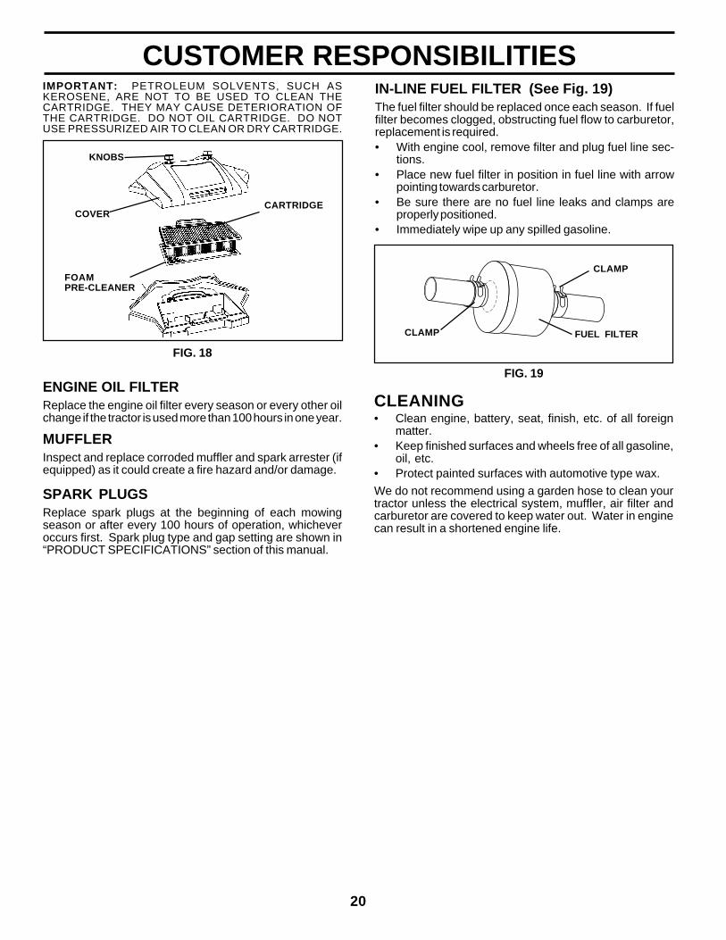
IN-LINE FUEL FILTER (See Fig. 19)The fuel filter should be replaced once each season. If fuelfilter becomes clogged, obstructing fuel flow to carburetor,replacement is required.• With engine cool, remove filter and plug fuel line sec-
tions.• Place new fuel filter in position in fuel line with arrow
pointing towards carburetor.• Be sure there are no fuel line leaks and clamps are
properly positioned.• Immediately wipe up any spilled gasoline.
ENGINE OIL FILTERReplace the engine oil filter every season or every other oilchange if the tractor is used more than 100 hours in one year.
21
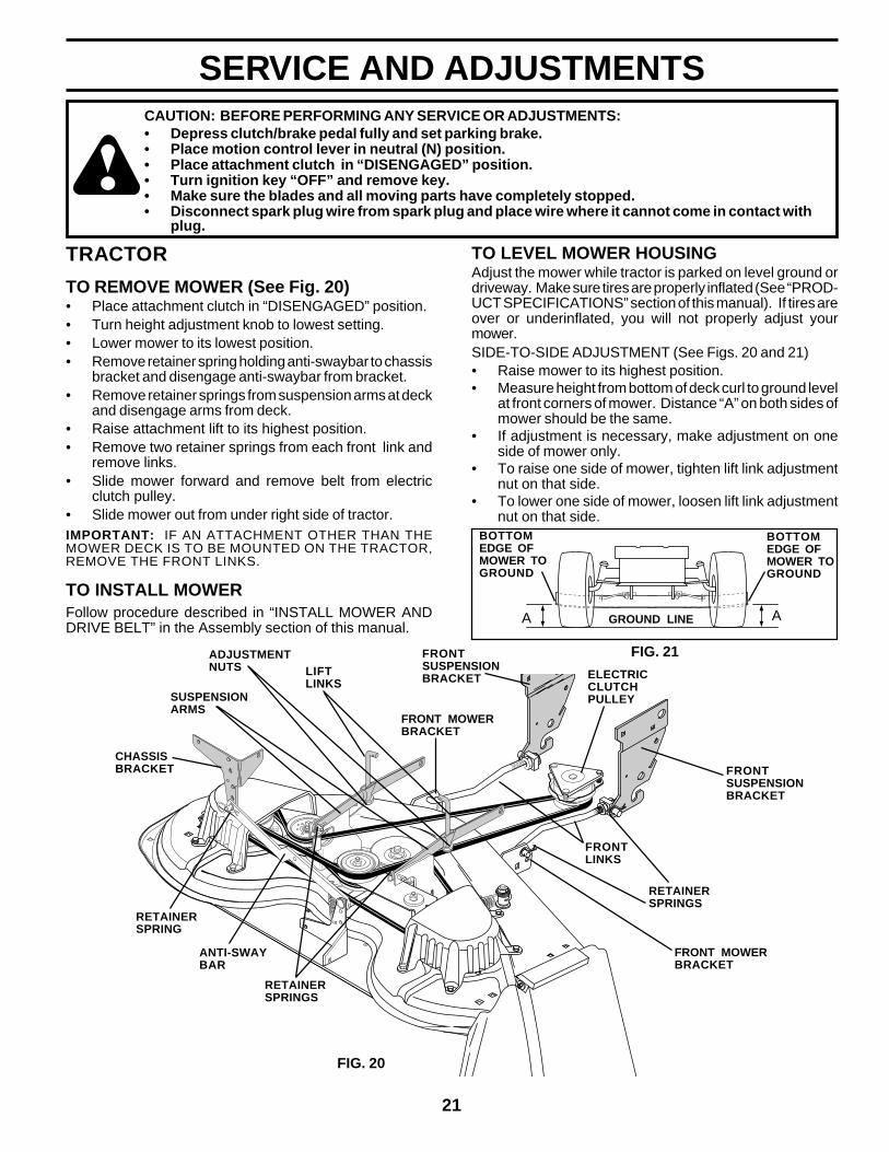
SERVICE AND ADJUSTMENTSCAUTION: BEFORE PERFORMING ANY SERVICE OR ADJUSTMENTS:• Depress clutch/brake pedal fully and set parking brake.• Place motion control lever in neutral (N) position.• Place attachment clutch in “DISENGAGED” position.• Turn ignition key “OFF” and remove key.• Make sure the blades and all moving parts have completely stopped.• Disconnect spark plug wire from spark plug and place wire where it cannot come in contact with
plug.
TO LEVEL MOWER HOUSINGAdjust the mower while tractor is parked on level ground ordriveway. Make sure tires are properly inflated (See “PROD-UCT SPECIFICATIONS” section of this manual). If tires areover or underinflated, you will not properly adjust yourmower.SIDE-TO-SIDE ADJUSTMENT (See Figs. 20 and 21)• Raise mower to its highest position.• Measure height from bottom of deck curl to ground level
at front corners of mower. Distance “A” on both sides ofmower should be the same.
• If adjustment is necessary, make adjustment on oneside of mower only.
• To raise one side of mower, tighten lift link adjustmentnut on that side.
• To lower one side of mower, loosen lift link adjustmentnut on that side.
FIG. 21
AA GROUND LINE
FRONTSUSPENSIONBRACKET
FRONTSUSPENSIONBRACKET
RETAINERSPRINGS
LIFTLINKS
FIG. 20
RETAINERSPRING
ADJUSTMENTNUTS
SUSPENSIONARMS
CHASSISBRACKET
FRONT MOWERBRACKET
ELECTRICCLUTCHPULLEY
ANTI-SWAYBAR
RETAINERSPRINGS
FRONTLINKS
FRONT MOWERBRACKET
TRACTOR
TO REMOVE MOWER (See Fig. 20)• Place attachment clutch in “DISENGAGED” position.• Turn height adjustment knob to lowest setting.• Lower mower to its lowest position.• Remove retainer spring holding anti-swaybar to chassis
bracket and disengage anti-swaybar from bracket.• Remove retainer springs from suspension arms at deck
and disengage arms from deck.• Raise attachment lift to its highest position.• Remove two retainer springs from each front link and
remove links.• Slide mower forward and remove belt from electric
clutch pulley.• Slide mower out from under right side of tractor.IMPORTANT: IF AN ATTACHMENT OTHER THAN THEMOWER DECK IS TO BE MOUNTED ON THE TRACTOR,REMOVE THE FRONT LINKS.
TO INSTALL MOWERFollow procedure described in “INSTALL MOWER ANDDRIVE BELT” in the Assembly section of this manual.
BOTTOMEDGE OFMOWER TOGROUND
BOTTOMEDGE OFMOWER TOGROUND
22
SERVICE AND ADJUSTMENTS
FRONT LINKS
NUT “H”
NUT “G”
FIG. 23
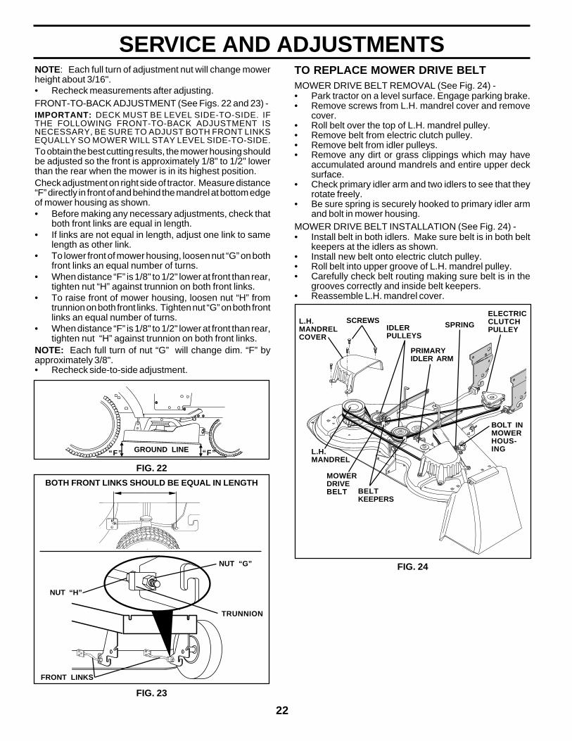
TO REPLACE MOWER DRIVE BELTMOWER DRIVE BELT REMOVAL (See Fig. 24) -• Park tractor on a level surface. Engage parking brake.• Remove screws from L.H. mandrel cover and remove
cover.• Roll belt over the top of L.H. mandrel pulley.• Remove belt from electric clutch pulley.• Remove belt from idler pulleys.• Remove any dirt or grass clippings which may have
accumulated around mandrels and entire upper decksurface.
• Check primary idler arm and two idlers to see that theyrotate freely.
• Be sure spring is securely hooked to primary idler armand bolt in mower housing.
MOWER DRIVE BELT INSTALLATION (See Fig. 24) -• Install belt in both idlers. Make sure belt is in both belt
keepers at the idlers as shown.• Install new belt onto electric clutch pulley.• Roll belt into upper groove of L.H. mandrel pulley.• Carefully check belt routing making sure belt is in the
grooves correctly and inside belt keepers.• Reassemble L.H. mandrel cover.
NOTE: Each full turn of adjustment nut will change mowerheight about 3/16".• Recheck measurements after adjusting.FRONT-TO-BACK ADJUSTMENT (See Figs. 22 and 23) -IMPORTANT: DECK MUST BE LEVEL SIDE-TO-SIDE. IFTHE FOLLOWING FRONT-TO-BACK ADJUSTMENT ISNECESSARY, BE SURE TO ADJUST BOTH FRONT LINKSEQUALLY SO MOWER WILL STAY LEVEL SIDE-TO-SIDE.To obtain the best cutting results, the mower housing shouldbe adjusted so the front is approximately 1/8" to 1/2" lowerthan the rear when the mower is in its highest position.Check adjustment on right side of tractor. Measure distance“F” directly in front of and behind the mandrel at bottom edgeof mower housing as shown.• Before making any necessary adjustments, check that
both front links are equal in length.• If links are not equal in length, adjust one link to same
length as other link.• To lower front of mower housing, loosen nut “G” on both
front links an equal number of turns.• When distance “F” is 1/8" to 1/2" lower at front than rear,
tighten nut “H” against trunnion on both front links.• To raise front of mower housing, loosen nut “H” from
trunnion on both front links. Tighten nut “G” on both frontlinks an equal number of turns.
• When distance “F” is 1/8" to 1/2" lower at front than rear,tighten nut “H” against trunnion on both front links.
NOTE: Each full turn of nut “G” will change dim. “F” byapproximately 3/8".• Recheck side-to-side adjustment.
BOTH FRONT LINKS SHOULD BE EQUAL IN LENGTH
FIG. 22
GROUND LINE “F”“F”
ELECTRICCLUTCHPULLEYIDLER
PULLEYS
PRIMARYIDLER ARM
SPRINGL.H.MANDRELCOVER
FIG. 24
SCREWS
BELTKEEPERS
MOWERDRIVEBELT
L.H.MANDREL
BOLT INMOWERHOUS-ING
TRUNNION
23
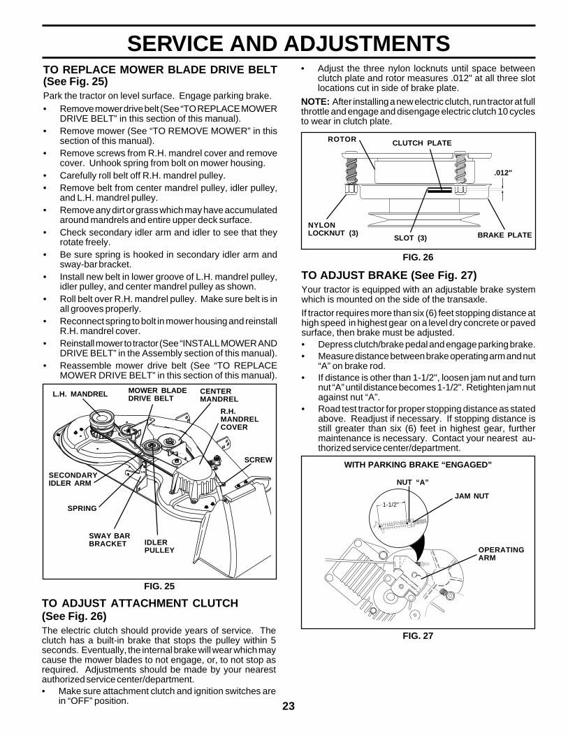
SERVICE AND ADJUSTMENTSTO REPLACE MOWER BLADE DRIVE BELT(See Fig. 25)Park the tractor on level surface. Engage parking brake.• Remove mower drive belt (See “TO REPLACE MOWER
DRIVE BELT” in this section of this manual).• Remove mower (See “TO REMOVE MOWER” in this
section of this manual).• Remove screws from R.H. mandrel cover and remove
cover. Unhook spring from bolt on mower housing.• Carefully roll belt off R.H. mandrel pulley.• Remove belt from center mandrel pulley, idler pulley,
and L.H. mandrel pulley.• Remove any dirt or grass which may have accumulated
around mandrels and entire upper deck surface.• Check secondary idler arm and idler to see that they
rotate freely.• Be sure spring is hooked in secondary idler arm and
sway-bar bracket.• Install new belt in lower groove of L.H. mandrel pulley,
idler pulley, and center mandrel pulley as shown.• Roll belt over R.H. mandrel pulley. Make sure belt is in
all grooves properly.• Reconnect spring to bolt in mower housing and reinstall
R.H. mandrel cover.• Reinstall mower to tractor (See “INSTALL MOWER AND
DRIVE BELT” in the Assembly section of this manual).• Reassemble mower drive belt (See “TO REPLACE
MOWER DRIVE BELT” in this section of this manual).
TO ADJUST ATTACHMENT CLUTCH(See Fig. 26)The electric clutch should provide years of service. Theclutch has a built-in brake that stops the pulley within 5seconds. Eventually, the internal brake will wear which maycause the mower blades to not engage, or, to not stop asrequired. Adjustments should be made by your nearestauthorized service center/department.• Make sure attachment clutch and ignition switches are
in “OFF” position.
ROTOR CLUTCH PLATE
.012"
NYLONLOCKNUT (3)
SLOT (3) BRAKE PLATE
FIG. 26
FIG. 25
MOWER BLADEDRIVE BELT
R.H.MANDRELCOVER
CENTERMANDREL
SCREW
L.H. MANDREL
SWAY BARBRACKET
SPRING
SECONDARYIDLER ARM
IDLERPULLEY
• Adjust the three nylon locknuts until space betweenclutch plate and rotor measures .012" at all three slotlocations cut in side of brake plate.
NOTE: After installing a new electric clutch, run tractor at fullthrottle and engage and disengage electric clutch 10 cyclesto wear in clutch plate.
TO ADJUST BRAKE (See Fig. 27)Your tractor is equipped with an adjustable brake systemwhich is mounted on the side of the transaxle.
If tractor requires more than six (6) feet stopping distance athigh speed in highest gear on a level dry concrete or pavedsurface, then brake must be adjusted.• Depress clutch/brake pedal and engage parking brake.• Measure distance between brake operating arm and nut
“A” on brake rod.• If distance is other than 1-1/2", loosen jam nut and turn
nut “A” until distance becomes 1-1/2". Retighten jam nutagainst nut “A”.
• Road test tractor for proper stopping distance as statedabove. Readjust if necessary. If stopping distance isstill greater than six (6) feet in highest gear, furthermaintenance is necessary. Contact your nearest au-thorized service center/department.
1-1/2"
OPERATINGARM
WITH PARKING BRAKE “ENGAGED”
NUT “A”
JAM NUT
FIG. 27
24
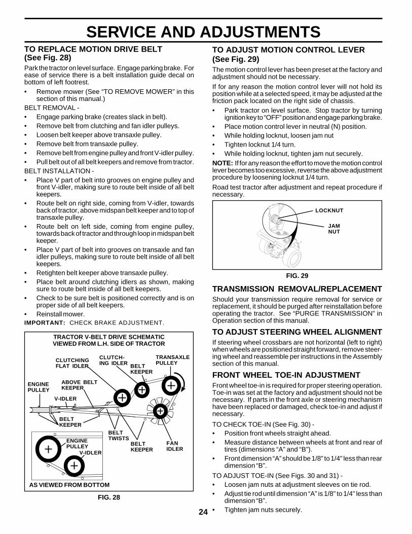
SERVICE AND ADJUSTMENTSTO REPLACE MOTION DRIVE BELT(See Fig. 28)Park the tractor on level surface. Engage parking brake. Forease of service there is a belt installation guide decal onbottom of left footrest.• Remove mower (See “TO REMOVE MOWER” in this
section of this manual.)BELT REMOVAL -• Engage parking brake (creates slack in belt).• Remove belt from clutching and fan idler pulleys.• Loosen belt keeper above transaxle pulley.• Remove belt from transaxle pulley.• Remove belt from engine pulley and front V-idler pulley.• Pull belt out of all belt keepers and remove from tractor.BELT INSTALLATION -• Place V part of belt into grooves on engine pulley and
front V-idler, making sure to route belt inside of all beltkeepers.
• Route belt on right side, coming from V-idler, towardsback of tractor, above midspan belt keeper and to top oftransaxle pulley.
• Route belt on left side, coming from engine pulley,towards back of tractor and through loop in midspan beltkeeper.
• Place V part of belt into grooves on transaxle and fanidler pulleys, making sure to route belt inside of all beltkeepers.
• Retighten belt keeper above transaxle pulley.• Place belt around clutching idlers as shown, making
sure to route belt inside of all belt keepers.• Check to be sure belt is positioned correctly and is on
proper side of all belt keepers.• Reinstall mower.IMPORTANT: CHECK BRAKE ADJUSTMENT.
TRACTOR V-BELT DRIVE SCHEMATICVIEWED FROM L.H. SIDE OF TRACTOR
V-IDLER
ENGINEPULLEY
BELTTWISTS
BELTKEEPER
BELTKEEPER
V-IDLER
AS VIEWED FROM BOTTOM
ABOVE BELTKEEPER
TRANSAXLEPULLEYCLUTCHING
FLAT IDLER
CLUTCH-ING IDLER BELT
KEEPER
ENGINEPULLEY
FANIDLER
FIG. 28
TO ADJUST MOTION CONTROL LEVER(See Fig. 29)The motion control lever has been preset at the factory andadjustment should not be necessary.
If for any reason the motion control lever will not hold itsposition while at a selected speed, it may be adjusted at thefriction pack located on the right side of chassis.• Park tractor on level surface. Stop tractor by turning
ignition key to “OFF” position and engage parking brake.• Place motion control lever in neutral (N) position.• While holding locknut, loosen jam nut• Tighten locknut 1/4 turn.• While holding locknut, tighten jam nut securely.NOTE: If for any reason the effort to move the motion controllever becomes too excessive, reverse the above adjustmentprocedure by loosening locknut 1/4 turn.
Road test tractor after adjustment and repeat procedure ifnecessary.
JAMNUT
FIG. 29
TRANSMISSION REMOVAL/REPLACEMENTShould your transmission require removal for service orreplacement, it should be purged after reinstallation beforeoperating the tractor. See “PURGE TRANSMISSION” inOperation section of this manual.
TO ADJUST STEERING WHEEL ALIGNMENTIf steering wheel crossbars are not horizontal (left to right)when wheels are positioned straight forward, remove steer-ing wheel and reassemble per instructions in the Assemblysection of this manual.
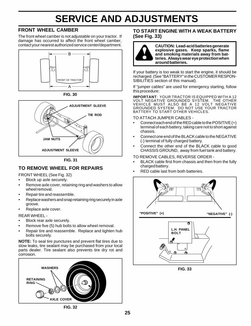
FRONT WHEEL TOE-IN ADJUSTMENTFront wheel toe-in is required for proper steering operation.Toe-in was set at the factory and adjustment should not benecessary. If parts in the front axle or steering mechanismhave been replaced or damaged, check toe-in and adjust ifnecessary.
TO CHECK TOE-IN (See Fig. 30) -• Position front wheels straight ahead.• Measure distance between wheels at front and rear of
tires (dimensions “A” and “B”).• Front dimension “A” should be 1/8" to 1/4" less than rear
dimension “B”.
TO ADJUST TOE-IN (See Figs. 30 and 31) -• Loosen jam nuts at adjustment sleeves on tie rod.• Adjust tie rod until dimension “A” is 1/8" to 1/4" less than
dimension “B”.• Tighten jam nuts securely.
LOCKNUT
25
SERVICE AND ADJUSTMENTS
A
B
FRONT OF TRACTOR
FIG. 30
TIE ROD
JAM NUTS
ADJUSTMENT SLEEVE
ADJUSTMENT SLEEVE
FIG. 31
FRONT WHEEL CAMBERThe front wheel camber is not adjustable on your tractor. Ifdamage has occurred to affect the front wheel camber,contact your nearest authorized service center/department.
FIG. 32
RETAININGRING
WASHERS
AXLE COVER
TO REMOVE WHEEL FOR REPAIRSFRONT WHEEL (See Fig. 32)• Block up axle securely.• Remove axle cover, retaining ring and washers to allow
wheel removal.• Repair tire and reassemble.• Replace washers and snap retaining ring securely in axle
groove.• Replace axle cover.
REAR WHEEL -• Block rear axle securely.• Remove five (5) hub bolts to allow wheel removal.• Repair tire and reassemble. Replace and tighten hub
bolts securely.
NOTE: To seal tire punctures and prevent flat tires due toslow leaks, tire sealant may be purchased from your localparts dealer. Tire sealant also prevents tire dry rot andcorrosion.
TO START ENGINE WITH A WEAK BATTERY(See Fig. 33)
CAUTION: Lead-acid batteries generateexplosive gases. Keep sparks, flameand smoking materials away from bat-teries. Always wear eye protection whenaround batteries.
If your battery is too weak to start the engine, it should berecharged. (See "BATTERY" in the CUSTOMER RESPON-SIBILITIES section of this manual).
If “jumper cables” are used for emergency starting, followthis procedure:IMPORTANT: YOUR TRACTOR IS EQUIPPED WITH A 12VOLT NEGATIVE GROUNDED SYSTEM. THE OTHERVEHICLE MUST ALSO BE A 12 VOLT NEGATIVEGROUNDED SYSTEM. DO NOT USE YOUR TRACTORBATTERY TO START OTHER VEHICLES.
TO ATTACH JUMPER CABLES -• Connect each end of the RED cable to the POSITIVE (+)
terminal of each battery, taking care not to short againstchassis.
• Connect one end of the BLACK cable to the NEGATIVE(-) terminal of fully charged battery.
• Connect the other end of the BLACK cable to goodCHASSIS GROUND, away from fuel tank and battery.
TO REMOVE CABLES, REVERSE ORDER -• BLACK cable first from chassis and then from the fully
charged battery.• RED cable last from both batteries.
“NEGATIVE” (-)“POSITIVE” (+)
L.H. PANELBOLT
FIG. 33
26
SERVICE AND ADJUSTMENTS
TO REPLACE HEADLIGHT BULB• Raise hood.• Pull bulb holder out of the hole in the backside of the grill.• Replace bulb in holder and push bulb holder securely
back into the hole in the backside of the grill.• Close hood.
INTERLOCKS AND RELAYSLoose or damaged wiring may cause your tractor to runpoorly, stop running, or prevent it from starting.• Check wiring. See electrical wiring diagram in the Repair
Parts section of this manual.
TO REPLACE FUSEReplace with 30 amp automotive-type plug-in fuse. The fuseholder is located behind the dash.
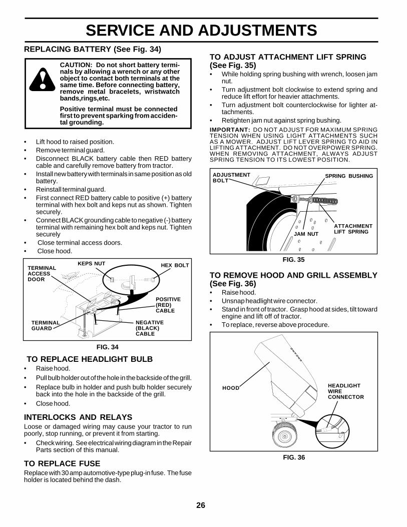
REPLACING BATTERY (See Fig. 34)
CAUTION: Do not short battery termi-nals by allowing a wrench or any otherobject to contact both terminals at thesame time. Before connecting battery,remove metal bracelets, wristwatchbands,rings,etc.
• Lift hood to raised position.• Remove terminal guard.• Disconnect BLACK battery cable then RED battery
cable and carefully remove battery from tractor.• Install new battery with terminals in same position as old
battery.• Reinstall terminal guard.• First connect RED battery cable to positive (+) battery
terminal with hex bolt and keps nut as shown. Tightensecurely.
• Connect BLACK grounding cable to negative (-) batteryterminal with remaining hex bolt and keps nut. Tightensecurely
• Close terminal access doors.• Close hood.
Positive terminal must be connectedfirst to prevent sparking from acciden-tal grounding.
HEX BOLTKEPS NUT
POSITIVE(RED)CABLE
NEGATIVE(BLACK)CABLE
TERMINALGUARD
TERMINALACCESSDOOR
FIG. 34
ADJUSTMENTBOLT
SPRING BUSHING
JAM NUTATTACHMENTLIFT SPRING
FIG. 35
TO ADJUST ATTACHMENT LIFT SPRING(See Fig. 35)• While holding spring bushing with wrench, loosen jam
nut.• Turn adjustment bolt clockwise to extend spring and
reduce lift effort for heavier attachments.• Turn adjustment bolt counterclockwise for lighter at-
tachments.• Retighten jam nut against spring bushing.IMPORTANT: DO NOT ADJUST FOR MAXIMUM SPRINGTENSION WHEN USING LIGHT ATTACHMENTS SUCHAS A MOWER. ADJUST LIFT LEVER SPRING TO AID INLIFTING ATTACHMENT. DO NOT OVERPOWER SPRING.WHEN REMOVING ATTACHMENT, ALWAYS ADJUSTSPRING TENSION TO ITS LOWEST POSITION.
TO REMOVE HOOD AND GRILL ASSEMBLY(See Fig. 36)• Raise hood.• Unsnap headlight wire connector.• Stand in front of tractor. Grasp hood at sides, tilt toward
engine and lift off of tractor.• To replace, reverse above procedure.
HOOD HEADLIGHTWIRECONNECTOR
FIG. 36
27
SERVICE AND ADJUSTMENTS
CLAMP SCREW
FIG. 38
FIG. 37
SWIVEL CLAMPSCREW
STOPENGINE
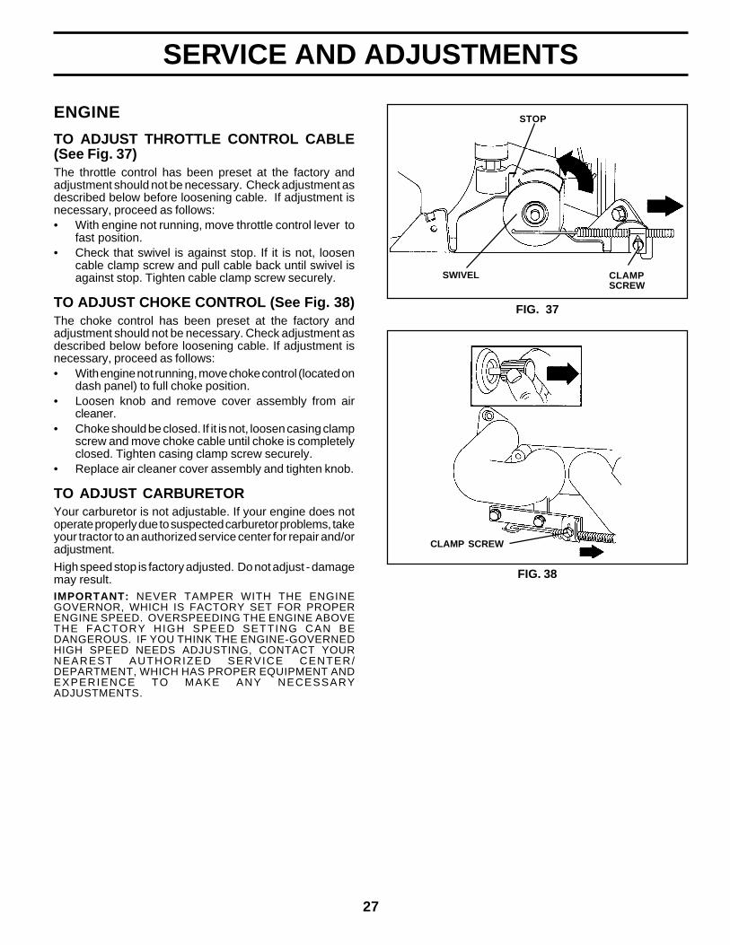
TO ADJUST THROTTLE CONTROL CABLE(See Fig. 37)The throttle control has been preset at the factory andadjustment should not be necessary. Check adjustment asdescribed below before loosening cable. If adjustment isnecessary, proceed as follows:• With engine not running, move throttle control lever to
fast position.• Check that swivel is against stop. If it is not, loosen
cable clamp screw and pull cable back until swivel isagainst stop. Tighten cable clamp screw securely.
TO ADJUST CHOKE CONTROL (See Fig. 38)The choke control has been preset at the factory andadjustment should not be necessary. Check adjustment asdescribed below before loosening cable. If adjustment isnecessary, proceed as follows:• With engine not running, move choke control (located on
dash panel) to full choke position.• Loosen knob and remove cover assembly from air
cleaner.• Choke should be closed. If it is not, loosen casing clamp
screw and move choke cable until choke is completelyclosed. Tighten casing clamp screw securely.
• Replace air cleaner cover assembly and tighten knob.
TO ADJUST CARBURETORYour carburetor is not adjustable. If your engine does notoperate properly due to suspected carburetor problems, takeyour tractor to an authorized service center for repair and/oradjustment.
High speed stop is factory adjusted. Do not adjust - damagemay result.IMPORTANT: NEVER TAMPER WITH THE ENGINEGOVERNOR, WHICH IS FACTORY SET FOR PROPERENGINE SPEED. OVERSPEEDING THE ENGINE ABOVETHE FACTORY HIGH SPEED SETTING CAN BEDANGEROUS. IF YOU THINK THE ENGINE-GOVERNEDHIGH SPEED NEEDS ADJUSTING, CONTACT YOURNEAREST AUTHORIZED SERVICE CENTER/DEPARTMENT, WHICH HAS PROPER EQUIPMENT ANDEXPERIENCE TO MAKE ANY NECESSARYADJUSTMENTS.
28
STORAGE
Immediately prepare your tractor for storage at the end of theseason or if the tractor will not be used for 30 days or more.
CAUTION: Never store the tractor withgasoline in the tank inside a buildingwhere fumes may reach an open flameor spark. Allow the engine to coolbefore storing in any enclosure.
TRACTORRemove mower from tractor for winter storage. When moweris to be stored for a period of time, clean it thoroughly,remove all dirt, grease, leaves, etc. Store in a clean, dryarea.• Clean entire tractor (See “CLEANING” in the Customer
Responsibilities section of this manual).• Inspect and replace belts, if necessary (See belt re-
placement instructions in the Service and Adjustmentssection of this manual).
• Lubricate as shown in the Customer Responsibilitiessection of this manual.
• Be sure that all nuts, bolts and screws are securelyfastened. Inspect moving parts for damage, breakageand wear. Replace if necessary.
• Touch up all rusted or chipped paint surfaces; sandlightly before painting.
BATTERY• Fully charge the battery for storage.• After a period of time in storage, battery may require
recharging.• To help prevent corrosion and power leakage during long
periods of storage, battery cables should be discon-nected and battery cleaned thoroughly (see “TO CLEANBATTERY AND TERMINALS” in the Customer Respon-sibilities section of this manual).
• After cleaning, leave cables disconnected and placecables where they cannot come in contact with batteryterminals.
• If battery is removed from tractor for storage, do notstore battery directly on concrete or damp surfaces.
ENGINE
FUEL SYSTEMIMPORTANT: IT IS IMPORTANT TO PREVENT GUMDEPOSITS FROM FORMING IN ESSENTIAL FUEL SYSTEMPARTS SUCH AS CARBURETOR, FUEL FILTER, FUELHOSE, OR TANK DURING STORAGE. ALSO,EXPERIENCE INDICATES THAT ALCOHOL BLENDEDFUELS (CALLED GASOHOL OR USING ETHANOL ORMETHANOL) CAN ATTRACT MOISTURE WHICH LEADSTO SEPARATION AND FORMATION OF ACIDS DURINGSTORAGE. ACIDIC GAS CAN DAMAGE THE FUELSYSTEM OF AN ENGINE WHILE IN STORAGE.• Drain the fuel tank.• Start the engine and let it run until the fuel lines and
carburetor are empty.• Never use engine or carburetor cleaner products in the
fuel tank or permanent damage may occur.• Use fresh fuel next season.
NOTE: Fuel stabilizer is an acceptable alternative inminimizing the formation of fuel gum deposits during stor-age. Add stabilizer to gasoline in fuel tank or storagecontainer. Always follow the mix ratio found on stabilizercontainer. Run engine at least 10 minutes after addingstabilizer to allow the stabilizer to reach the carburetor. Donot drain the gas tank and carburetor if using fuel stabilizer.
ENGINE OILDrain oil (with engine warm) and replace with clean engine oil.(See “ENGINE” in the Customer Responsibilities section ofthis manual).
CYLINDER(S)• Remove spark plug(s).• Pour one ounce of oil through spark plug hole(s) into
cylinder(s).• Turn ignition key to “START” position for a few seconds
to distribute oil.• Replace with new spark plug(s).
OTHER• Do not store gasoline from one season to another.• Replace your gasoline can if your can starts to rust.
Rust and/or dirt in your gasoline will cause problems.• If possible, store your tractor indoors and cover it to give
protection from dust and dirt.• Cover your tractor with a suitable protective cover that
does not retain moisture. Do not use plastic. Plasticcannot breathe which allows condensation to form andwill cause your tractor to rust.
IMPORTANT: NEVER COVER TRACTOR WHILE ENGINEAND EXHAUST AREAS ARE STILL WARM.

29
Will not start 1. Out of fuel. 1. Fill fuel tank.2. Engine not “CHOKED” properly. 2. See “TO START ENGINE” in Operation section.3. Engine flooded. 3. Wait several minutes before attempting to start.4. Bad spark plug. 4. Replace spark plug.5. Dirty air filter. 5. Clean/replace air filter.6. Dirty fuel filter. 6. Replace fuel filter.7. Water in fuel. 7. Drain fuel tank and carburetor, refill tank with fresh
gasoline and replace fuel filter.8. Loose or damaged wiring. 8. Check all wiring.9. Carburetor out of adjustment. 9. See “To Adjust Carburetor” in Service Adjustments
section.10. Engine valves out of adjustment. 10. Contact an authorized service center/department.
Hard to start 1. Dirty air filter. 1. Clean/replace air filter.2. Bad spark plug. 2. Replace spark plug.3. Weak or dead battery. 3. Recharge or replace battery.4. Dirty fuel filter. 4. Replace fuel filter.5. Stale or dirty fuel. 5. Drain fuel tank and refill with fresh gasoline.6. Loose or damaged wiring. 6. Check all wiring.7. Carburetor out of adjustment. 7. See “To Adjust Carburetor” in Service Adjustments
section.8. Engine valves out of adjustment. 8. Contact an authorized service center/department.
Engine will not turn over 1. Clutch/brake pedal not depressed. 1. Depress clutch/brake pedal.2. Attachment clutch is engaged. 2. Disengage attachment clutch.3. Weak or dead battery. 3. Recharge or replace battery.4. Blown fuse. 4. Replace fuse.5. Corroded battery terminals. 5. Clean battery terminals.6. Loose or damaged wiring. 6. Check all wiring.7. Faulty ignition switch. 7. Check/replace ignition switch.8. Faulty solenoid or starter. 8. Check/replace solenoid or starter.9. Faulty operator presence switch(es). 9. Contact an authorized service center/department.
Engine clicks but will not 1. Weak or dead battery. 1. Recharge or replace battery.start 2. Corroded battery terminals. 2. Clean battery terminals.
3. Loose or damaged wiring. 3. Check all wiring.4. Faulty solenoid or starter. 4. Check/replace solenoid or starter.
Loss of power 1. Cutting too much grass/too fast. 1. Set in “Higher Cut” position/reduce speed.2. Throttle in “CHOKE” position. 2. Adjust throttle control.3. Build-up of grass, leaves and trash under mower. 3. Clean underside of mower housing.4. Dirty air filter. 4. Clean/replace air filter.5. Low oil level/dirty oil. 5. Check oil level/change oil.6. Faulty spark plug. 6. Clean and regap or change spark plug.7. Dirty fuel filter. 7. Replace fuel filter.8. Stale or dirty fuel. 8. Drain fuel tank and refill with fresh gasoline.9. Water in fuel. 9. Drain fuel tank and carburetor, refill tank with fresh
gasoline and replace fuel filter.10. Spark plug wire loose. 10. Connect and tighten spark plug wire.11. Dirty engine air screen/fins. 11. Clean engine air screen/fins.12. Dirty/clogged muffler. 12. Clean/replace muffler.13. Loose or damaged wiring. 13. Check all wiring.14. Carburetor out of adjustment. 14. See “To Adjust Carburetor” in Service Adjustments
section.15. Engine valves out of adjustment. 15. Contact an authorized service center/department.
Excessive vibration 1. Worn, bent or loose blade. 1. Replace blade. Tighten blade bolt.2. Bent blade mandrel. 2. Replace blade mandrel.3. Loose/damaged part(s). 3. Tighten loose part(s). Replace damaged parts.
PROBLEM CAUSE CORRECTION
TROUBLESHOOTING POINTS

30
Engine continues to run 1. Faulty operator-safety presence control system. 1. Check wiring, switches and connections. If notwhen operator leaves seat corrected, contact an authorized service center/with attachment clutch department.engaged
Poor cut - uneven 1. Worn, bent or loose blade. 1. Replace blade. Tighten blade bolt.2. Mower deck not level. 2. Level mower deck.3. Buildup of grass, leaves, and trash under mower. 3. Clean underside of mower housing.4. Bent blade mandrel. 4. Replace blade mandrel.5. Clogged mower deck vent holes from buildup of 5. Clean around mandrels to open vent holes.
grass, leaves, and trash around mandrels.
Mower blades will not 1. Obstruction in clutch mechanism. 1. Remove obstruction.rotate 2. Worn/damaged mower drive belt. 2. Replace mower drive belt.
3. Frozen idler pulley. 3. Replace idler pulley.4. Frozen blade mandrel. 4. Replace blade mandrel.
Poor grass discharge 1. Engine speed too slow. 1. Place throttle control in “FAST” position.2. Travel speed too fast. 2. Shift to slower speed.3. Wet grass. 3. Allow grass to dry before mowing.4. Mower deck not level. 4. Level mower deck.5. Low/uneven tire air pressure. 5. Check tires for proper air pressure.6. Worn, bent or loose blade. 6. Replace/sharpen blade. Tighten blade bolt.7. Buildup of grass, leaves and trash under mower. 7. Clean underside of mower housing.8. Mower drive belt worn. 8. Replace mower drive belt.9. Blades improperly installed. 9. Reinstall blades sharp edge down.
10. Improper blades used. 10. Replace with blades listed in this manual.11. Clogged mower deck vent holes from buildup of 11. Clean around mandrels to open vent holes.
grass, leaves, and trash around mandrels.
Headlight(s) not working 1. Switch is “OFF”. 1. Turn switch “ON”.(if so equipped) 2. Bulb(s) burned out. 2. Replace bulb(s).
3. Faulty light switch. 3. Check/replace light switch.4. Loose or damaged wiring. 4. Check wiring and connections.5. Blown fuse. 5. Replace fuse.
Battery will not charge 1. Bad battery cell(s). 1. Replace battery.2. Poor cable connections. 2. Check/clean all connections.3. Faulty regulator (if so equipped). 3. Replace regulator.4. Faulty alternator. 4. Replace alternator.
Loss of drive 1. Freewheel control in “disengaged” position. 1. Place freewheel control in “engaged” position.2. Motion drive belt worn, damaged, or broken. 2. Replace motion drive belt.3. Air trapped in transmission during shipment 3. Purge transmission.
or servicing.
Engine “backfires” 1. Engine throttle control not set at “SLOW” 1. Move throttle control to “SLOW” position and allowwhen turning engine position for 30 seconds before stopping engine. to idle for 30 seconds before stopping engine.“OFF”
PROBLEM CAUSE CORRECTION
TROUBLESHOOTING POINTS
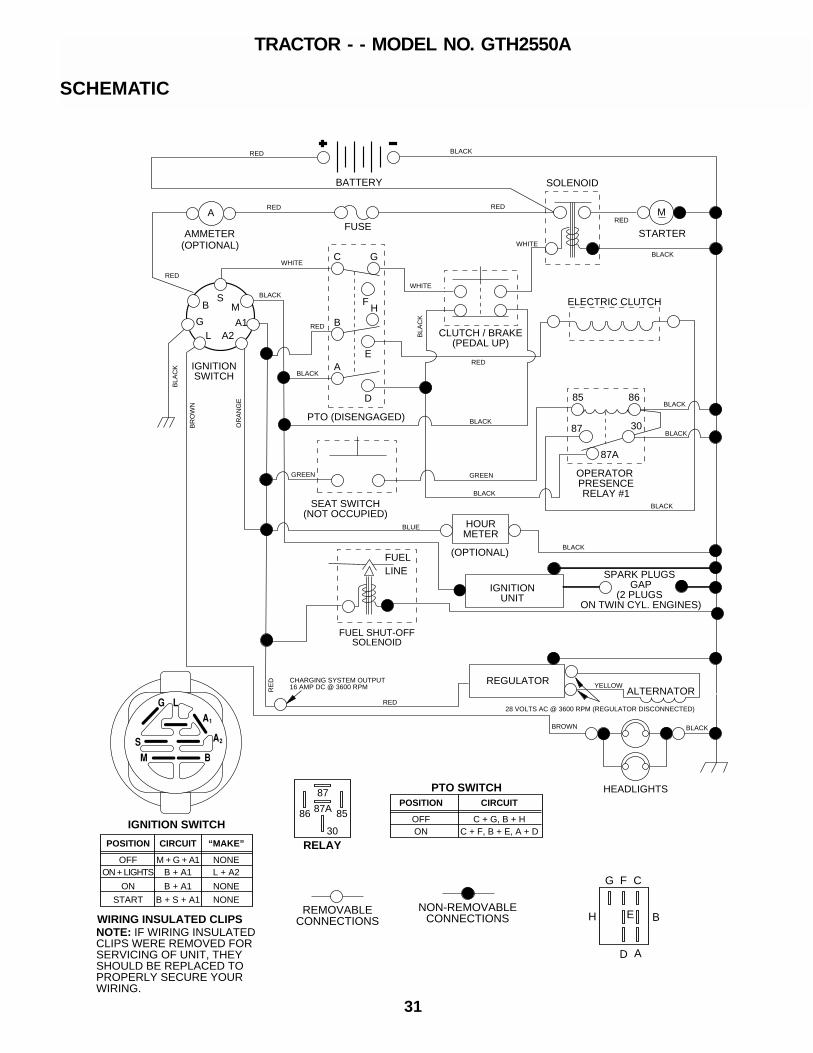
31
REPAIR PARTSTRACTOR - - MODEL NO. GTH2550A
BATTERY
FUSE RED
RED BLACK
BLACK
BLACK
BLACK
BLACK
BLACK
BLACK
BLACK
BLACK
NON-REMOVABLECONNECTIONS
REMOVABLECONNECTIONS
BLA
CK
BLA
CK
BR
OW
N
RE
D
OR
AN
GE
BROWN
M
SOLENOID
WIRING INSULATED CLIPSNOTE: IF WIRING INSULATED CLIPS WERE REMOVED FOR SERVICING OF UNIT, THEY SHOULD BE REPLACED TO PROPERLY SECURE YOUR WIRING.
A
AMMETER
RED
IGNITION SWITCH
CIRCUITPOSITION
OFFB + A1ON + LIGHTS
B + S + A1START
M + G + A1
B + A1ON
“MAKE”
L + A2
NONE
NONE
NONE
(OPTIONAL)
HEADLIGHTS
BLACK
ELECTRIC CLUTCH
CLUTCH / BRAKE(PEDAL UP)
PTO (DISENGAGED)
C G
F
B
EA
D
H
RED
GREEN GREEN
BLUE
RED
RED
RED
WHITE
WHITE
WHITE
BLACK
HOURMETER
(OPTIONAL)
STARTER
PTO SWITCHCIRCUITPOSITION
OFFC + F, B + E, A + DON
C + G, B + H
B
A
G
H
D
F C
E
IGNITIONSWITCH
G
BS
M
A1A2L
OPERATOR PRESENCERELAY #1
85 86
3087
87A
SEAT SWITCH(NOT OCCUPIED)
87
87A 8586
30RELAY
FUELLINE
RED28 VOLTS AC @ 3600 RPM (REGULATOR DISCONNECTED)
IGNITIONUNIT
ALTERNATORYELLOWREGULATORCHARGING SYSTEM OUTPUT
16 AMP DC @ 3600 RPM
SPARK PLUGS GAP
(2 PLUGS ON TWIN CYL. ENGINES)
FUEL SHUT-OFFSOLENOID
TRACTOR - - MODEL NO. GTH2550A
SCHEMATIC
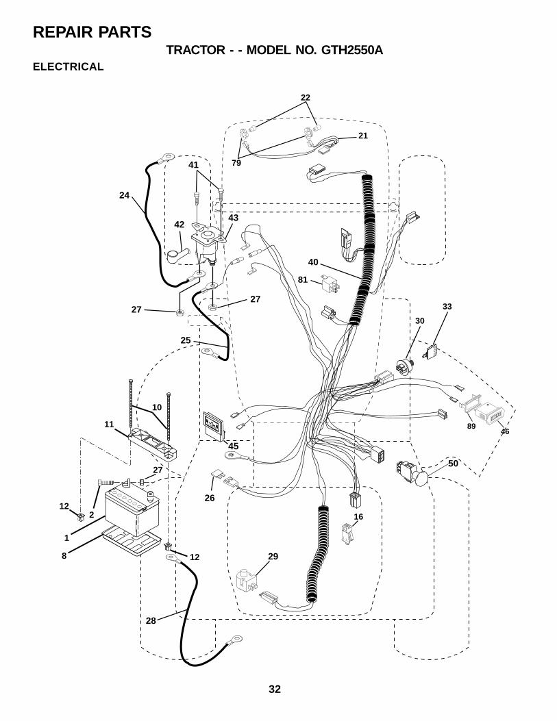
32
REPAIR PARTSTRACTOR - - MODEL NO. GTH2550A
ELECTRICAL
30
33
24
4243
40
26
28
25
50
29
2727
41
12
12
11
10
8
2
1
27
16
81
D.C. AMPERES
45
22
21
79
4689

33
REPAIR PARTSTRACTOR - - MODEL NO. GTH2550A
KEY PARTNO. NO. DESCRIPTION
1 532144926 Battery2 874760412 Bolt Hex Head 1/4-20 x 3/48 532124886 Tray, Battery10 532145211 Bolt, Battery Front 1/4-20 x 7.5 Zinc11 532150109 Holddown Battery Front Mount12 532145769 Nut, Push Nylon 1.4" Battery Front16 532153664 Switch Interlock Push-In21 532166184 Harness Socket Light w/4152J22 532004152 Bulb Light24 532124770 Cable, Battery25 532146149 Cable, Battery26 532108824 Fuse27 873510400 Nut Keps Hex 1/4-2028 532170697 Cable, Ground29 532160784 Switch, Plunger Normal Op Olive30 532175566 Switch, Ign33 532140401 Key40 532170238 Harness Ign.41 817720408 Screw 1/4-20 x 1/242 532131563 Cover, Terminal Red43 532175141 Solenoid45 532122822 Ammeter46 532169635 Hourmeter Snap-In50 532174651 Switch, PTO79 532163996 Bulbholder Asm81 532109748 Relay Asm.89 532169639 Bracket Snap-In Hourmeter
NOTE: All component dimensions given in U.S. inches1 inch = 25.4 mm
ELECTRICAL
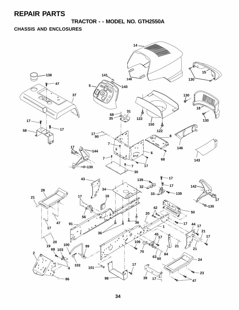
34
REPAIR PARTSTRACTOR - - MODEL NO. GTH2550A
3168
146
43
34
20
21
84
47
24
39 1786
4
2
1920
1617
56
21
4717
28
911
143
36
36
5042
17
17
17
21
21
44
23
106
8
68
1790
17
6
7
7
7
30
45
70
60
17
63
99100
17
98
101102
10368
35
15
130
5 140
141
14
18
130
130
47
37
17
17
58
138
14417
130
142
17
130
32
17139
17
33 139
122
150
122
148
CHASSIS AND ENCLOSURES
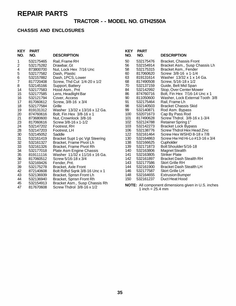
35
REPAIR PARTSTRACTOR - - MODEL NO. GTH2550A
1 532175465 Rail, Frame RH2 532175282 Drawbar, Gt4 873800700 Nut, Lock Hex 7/16 Unc5 532177582 Dash, Plastic6 532157882 Dash, 1PCS, Lower7 817720408 Screw, Thd Cut 1/4-20 x 1/28 532145166 Support, Battery14 532177583 Hood Asm., Pnt15 532177585 Lens, Headlight Bar16 532121794 Cover, Access17 817060612 Screw, 3/8-16 x 3/418 532177584 Grille19 819131312 Washer 13/32 x 13/16 x 12 Ga.20 874760616 Bolt, Fin Hex 3/8-16 x 121 873680600 Nut, Crownlock 3/8-1623 817060616 Screw 3/8-16 x 1-1/224 532147202 Footrest, RH28 532147203 Footrest, LH30 532145052 Saddle31 532161419 Bracket Supt 1-pc Vgt Steering32 532161327 Bracket, Frame Pivot Lh33 532161326 Bracket, Frame Pivot Rh34 532177018 Plate Asm Engine Chassis35 819111116 Washer 11/32 x 11/16 x 16 Ga.36 817060512 Screw 5/16-18 x 3/437 532169426 Fender, Pnt.39 532175278 Bracket, Axle Front42 872140608 Bolt Rdhd Sqnk 3/8-16 Unc x 143 532136939 Bracket, Spnsn Front Lh44 532136940 Bracket, Spnsn Front Rh45 532154913 Bracket Asm., Susp Chassis Rh47 817670608 Screw Thdrol 3/8-16 x 1/2
KEY PARTNO. NO. DESCRIPTION
50 532175476 Bracket, Chassis Front56 532154914 Bracket Asm., Susp Chassis Lh58 532175315 Bracket Asm., Fender60 817060620 Screw 3/8-16 x 1-1/463 819131614 Washer 13/32 x 1 x 14 Ga.68 817490508 Screw, 5/16-18 x 1/270 532137159 Guide, Belt Mid Span84 532142992 Stop, Over Center Mower86 874760716 Bolt, Fin Hex 7/16-14 Unc x 190 811050600 Washer, Lock External Tooth 3/891 532175464 Rail, Frame Lh98 532140503 Bracket Chassis Skid99 532140871 Rod Asm. Bypass100 532071673 Cap By Pass Rod101 817490628 Screw Thdrol. 3/8-16 x 1-3/4102 532124788 Retainer Spring 1"103 532142273 Bracket Lock Bypass106 532138776 Screw Thdrol Hex Head Zinc122 532161464 Screw Hex WSHD 8-18 x 7/8130 532164863 Screw Hw Hd Hi-Lo #13-16 x 3/4138 532166625 Cupholder139 532171873 Bolt Shoulder 5/16-18140 532163806 Magnet Stealth141 532163805 Striker Plate142 532161897 Bracket Dash Stealth RH143 532177586 Skirt Grille RH144 532161900 Bracket Dash Stealth LH146 532177587 Skirt Grille LH148 532164655 Extrusion Bumper150 532161237 Duct Heat Hood
KEY PARTNO. NO. DESCRIPTION
NOTE: All component dimensions given in U.S. inches1 inch = 25.4 mm
CHASSIS AND ENCLOSURES
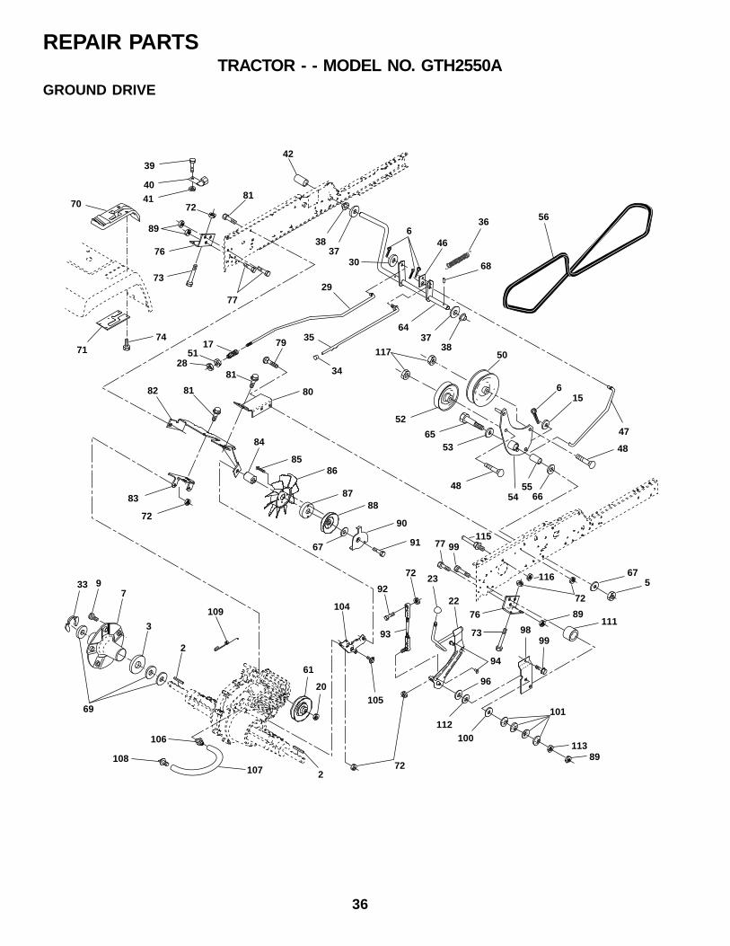
36
REPAIR PARTSTRACTOR - - MODEL NO. GTH2550A
GROUND DRIVE
9
117 50
615
4853
55
52
54
65
66
3
69
733
51
34
35
3738
4041
42
68
46
36
3738
64
48
47
39
675
56
29
72
72
89
76
73
77
70
7174
8976
9998
94
73
96
101
100112
8972
72
22
23
9991
90
8887
8685
84
80
79
8182
81
83
72
67
92
93
104
10520
61
2
2
109
17
113
77
6
30
111
116
115
107
106
108
8128
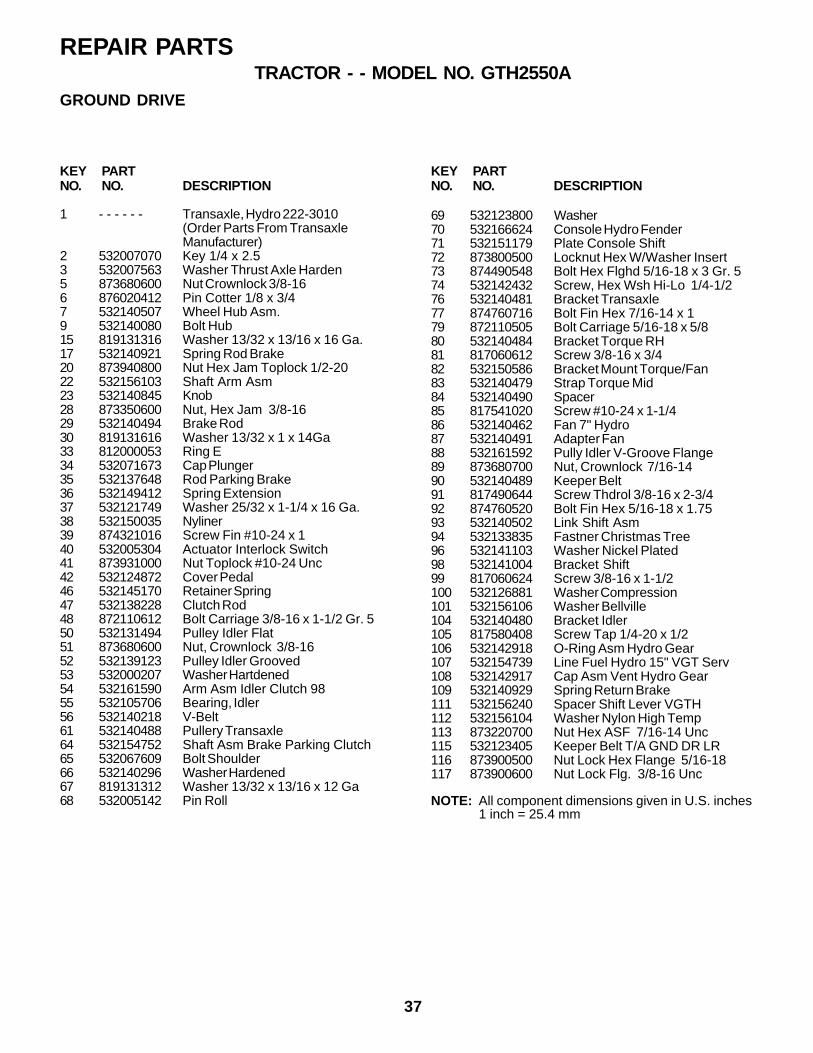
37
REPAIR PARTSTRACTOR - - MODEL NO. GTH2550A
KEY PARTNO. NO. DESCRIPTION
KEY PARTNO. NO. DESCRIPTION
1 - - - - - - Transaxle, Hydro 222-3010(Order Parts From TransaxleManufacturer)
2 532007070 Key 1/4 x 2.53 532007563 Washer Thrust Axle Harden5 873680600 Nut Crownlock 3/8-166 876020412 Pin Cotter 1/8 x 3/47 532140507 Wheel Hub Asm.9 532140080 Bolt Hub15 819131316 Washer 13/32 x 13/16 x 16 Ga.17 532140921 Spring Rod Brake20 873940800 Nut Hex Jam Toplock 1/2-2022 532156103 Shaft Arm Asm23 532140845 Knob28 873350600 Nut, Hex Jam 3/8-1629 532140494 Brake Rod30 819131616 Washer 13/32 x 1 x 14Ga33 812000053 Ring E34 532071673 Cap Plunger35 532137648 Rod Parking Brake36 532149412 Spring Extension37 532121749 Washer 25/32 x 1-1/4 x 16 Ga.38 532150035 Nyliner39 874321016 Screw Fin #10-24 x 140 532005304 Actuator Interlock Switch41 873931000 Nut Toplock #10-24 Unc42 532124872 Cover Pedal46 532145170 Retainer Spring47 532138228 Clutch Rod48 872110612 Bolt Carriage 3/8-16 x 1-1/2 Gr. 550 532131494 Pulley Idler Flat51 873680600 Nut, Crownlock 3/8-1652 532139123 Pulley Idler Grooved53 532000207 Washer Hartdened54 532161590 Arm Asm Idler Clutch 9855 532105706 Bearing, Idler56 532140218 V-Belt61 532140488 Pullery Transaxle64 532154752 Shaft Asm Brake Parking Clutch65 532067609 Bolt Shoulder66 532140296 Washer Hardened67 819131312 Washer 13/32 x 13/16 x 12 Ga68 532005142 Pin Roll
69 532123800 Washer70 532166624 Console Hydro Fender71 532151179 Plate Console Shift72 873800500 Locknut Hex W/Washer Insert73 874490548 Bolt Hex Flghd 5/16-18 x 3 Gr. 574 532142432 Screw, Hex Wsh Hi-Lo 1/4-1/276 532140481 Bracket Transaxle77 874760716 Bolt Fin Hex 7/16-14 x 179 872110505 Bolt Carriage 5/16-18 x 5/880 532140484 Bracket Torque RH81 817060612 Screw 3/8-16 x 3/482 532150586 Bracket Mount Torque/Fan83 532140479 Strap Torque Mid84 532140490 Spacer85 817541020 Screw #10-24 x 1-1/486 532140462 Fan 7" Hydro87 532140491 Adapter Fan88 532161592 Pully Idler V-Groove Flange89 873680700 Nut, Crownlock 7/16-1490 532140489 Keeper Belt91 817490644 Screw Thdrol 3/8-16 x 2-3/492 874760520 Bolt Fin Hex 5/16-18 x 1.7593 532140502 Link Shift Asm94 532133835 Fastner Christmas Tree96 532141103 Washer Nickel Plated98 532141004 Bracket Shift99 817060624 Screw 3/8-16 x 1-1/2100 532126881 Washer Compression101 532156106 Washer Bellville104 532140480 Bracket Idler105 817580408 Screw Tap 1/4-20 x 1/2106 532142918 O-Ring Asm Hydro Gear107 532154739 Line Fuel Hydro 15" VGT Serv108 532142917 Cap Asm Vent Hydro Gear109 532140929 Spring Return Brake111 532156240 Spacer Shift Lever VGTH112 532156104 Washer Nylon High Temp113 873220700 Nut Hex ASF 7/16-14 Unc115 532123405 Keeper Belt T/A GND DR LR116 873900500 Nut Lock Hex Flange 5/16-18117 873900600 Nut Lock Flg. 3/8-16 Unc
NOTE: All component dimensions given in U.S. inches1 inch = 25.4 mm
GROUND DRIVE

38
REPAIR PARTSTRACTOR - - MODEL NO. GTH2550A
STEERING ASSEMBLY
8629
28
23
31
41
22
21
20
44
145
14
25
34
3332
6
27
42
27
6
19
151435
18
16
987
2
66
4
1415 14
1415
9
3
8 7 3
66
5
1313
7 8
1415
14
14
36
38,40
37,39
17
14
26
12
1011
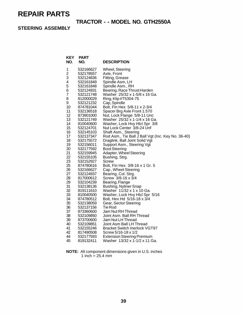
39
1 532166627 Wheel, Steering2 532178557 Axle, Front3 532124836 Fitting, Grease4 532161849 Spindle Asm, LH5 532161848 Spindle Asm., RH6 532124931 Bearing, Race Thrust Harden7 532121748 Washer 25/32 x 1-5/8 x 16 Ga.8 812000029 Ring, Klip #T5304-759 532121232 Cap, Spindle10 874781044 Bolt, Fin Hex 5/8-11 x 2-3/411 532136518 Spacer Brg Axle Front 1.57012 873901000 Nut, Lock Flange 5/8-11 Unc13 532121749 Washer 25/32 x 1-1/4 x 16 Ga.14 810040600 Washer, Lock Hvy Hlcl Spr 3/815 532124701 Nut Lock Center 3/8-24 Unf16 532145103 Shaft Asm., Steering17 532137347 Rod Asm., Tie Ball J Ball Vgt (Inc. Key No. 36-40)18 532175572 Draglink, Ball Joint Solid Vgt19 532156011 Support Asm., Steering Vgt20 532177592 Boot Steering21 532159945 Adapter, Wheel Steering22 532155105 Bushing, Strg.23 532152927 Screw25 874780616 Bolt, Fin Hex 3/8-16 x 1 Gr. 526 532166627 Cap , Wheel Steering27 532124937 Bearing, Col. Strg.28 817000612 Screw 3/8-16 x 3/429 532104239 Bearing, Flange31 532138136 Bushing, Nyliner Snap32 819111610 Washer 11/32 x 1 x 10 Ga.33 810040500 Washer, Lock Hvy Hlcl Spr 5/1634 874780512 Bolt, Hex Hd 5/16-18 x 3/435 532138059 Gear, Sector Steering36 532137156 Tie Rod37 873360600 Jam Nut RH Thread38 532109850 Joint Asm. Ball RH Thread39 873700600 Jam Nut LH Thread40 532109851 Joint Asm Ball LH Thread41 532155246 Bracket Switch Inerlock VGT9742 817490508 Screw 5/16-18 x 1/244 532177593 Extension Steering Premium45 819132411 Washer 13/32 x 1-1/2 x 11 Ga.
KEY PARTNO. NO. DESCRIPTION
NOTE: All component dimensions given in U.S. inches 1 inch = 25.4 mm
REPAIR PARTSTRACTOR - - MODEL NO. GTH2550A
STEERING ASSEMBLY
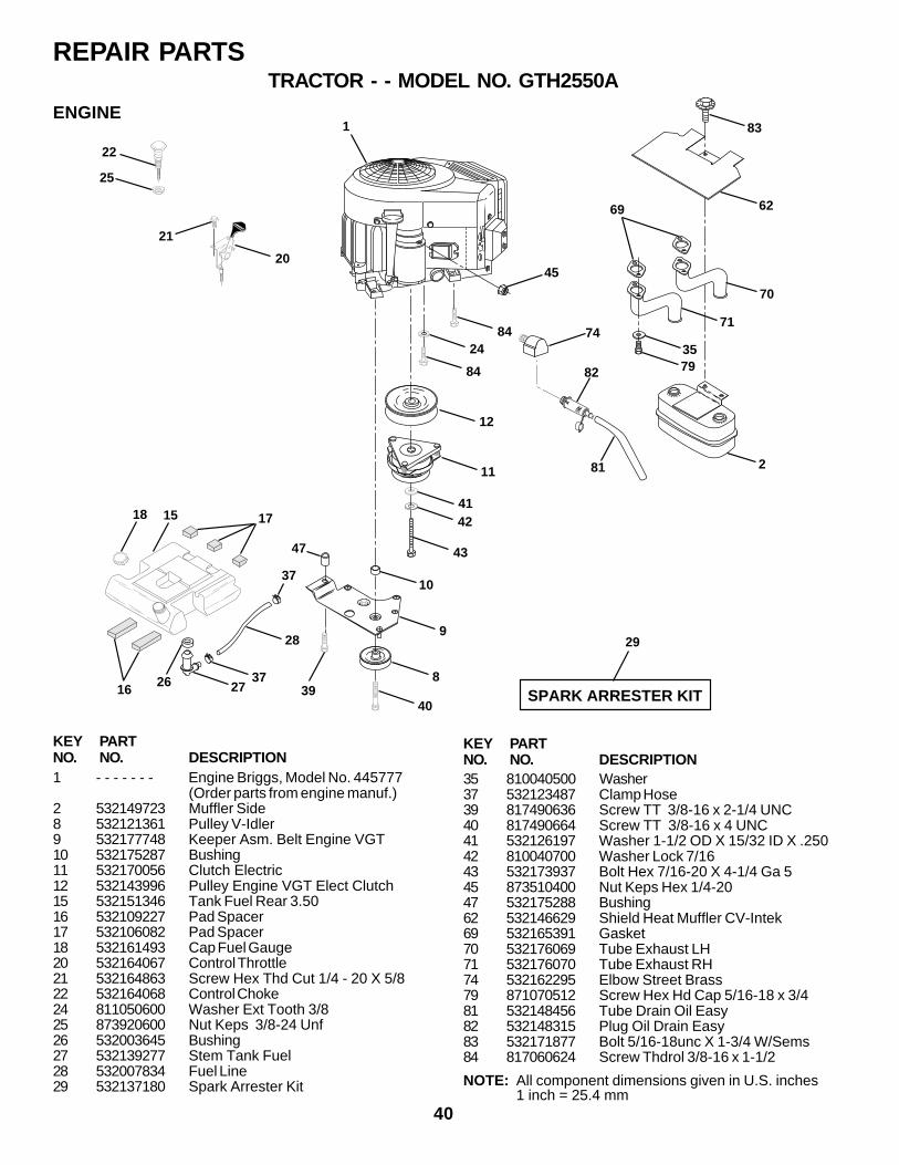
40
REPAIR PARTSTRACTOR - - MODEL NO. GTH2550A
1
84
24
12
11
4142
43
10
9
8
40
29
SPARK ARRESTER KIT
84
45
47
39
18 15 17
37
28
372726
16
22
25
21
20
74
62
70
71
79
69
83
35
281
82
KEY PARTNO. NO. DESCRIPTION1 - - - - - - - Engine Briggs, Model No. 445777
(Order parts from engine manuf.)2 532149723 Muffler Side8 532121361 Pulley V-Idler9 532177748 Keeper Asm. Belt Engine VGT10 532175287 Bushing11 532170056 Clutch Electric12 532143996 Pulley Engine VGT Elect Clutch15 532151346 Tank Fuel Rear 3.5016 532109227 Pad Spacer17 532106082 Pad Spacer18 532161493 Cap Fuel Gauge20 532164067 Control Throttle21 532164863 Screw Hex Thd Cut 1/4 - 20 X 5/822 532164068 Control Choke24 811050600 Washer Ext Tooth 3/825 873920600 Nut Keps 3/8-24 Unf26 532003645 Bushing27 532139277 Stem Tank Fuel28 532007834 Fuel Line29 532137180 Spark Arrester Kit
ENGINE
NOTE: All component dimensions given in U.S. inches1 inch = 25.4 mm
KEY PARTNO. NO. DESCRIPTION35 810040500 Washer37 532123487 Clamp Hose39 817490636 Screw TT 3/8-16 x 2-1/4 UNC40 817490664 Screw TT 3/8-16 x 4 UNC41 532126197 Washer 1-1/2 OD X 15/32 ID X .25042 810040700 Washer Lock 7/1643 532173937 Bolt Hex 7/16-20 X 4-1/4 Ga 545 873510400 Nut Keps Hex 1/4-2047 532175288 Bushing62 532146629 Shield Heat Muffler CV-Intek69 532165391 Gasket70 532176069 Tube Exhaust LH71 532176070 Tube Exhaust RH74 532162295 Elbow Street Brass79 871070512 Screw Hex Hd Cap 5/16-18 x 3/481 532148456 Tube Drain Oil Easy82 532148315 Plug Oil Drain Easy83 532171877 Bolt 5/16-18unc X 1-3/4 W/Sems84 817060624 Screw Thdrol 3/8-16 x 1-1/2
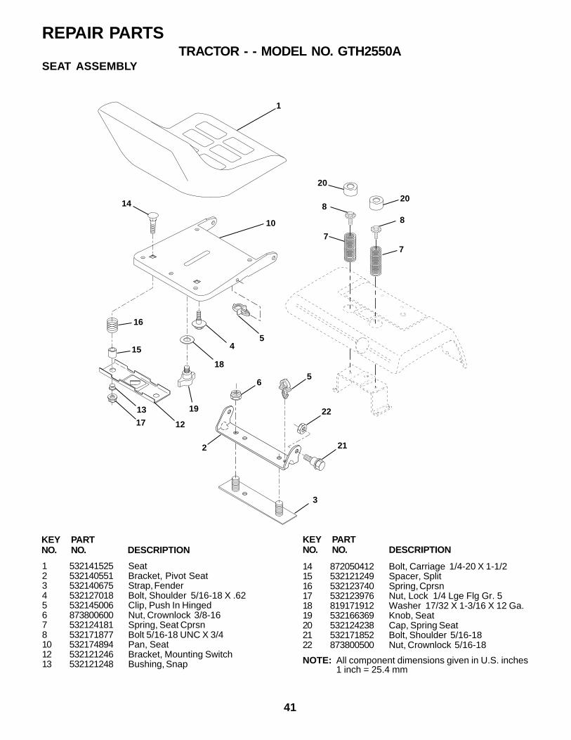
41
REPAIR PARTSTRACTOR - - MODEL NO. GTH2550A
1
10
5
18
19
16
15
12
13
17
4
14
2
6
22
21
7
7
3
5
20
820
8
1 532141525 Seat2 532140551 Bracket, Pivot Seat3 532140675 Strap, Fender4 532127018 Bolt, Shoulder 5/16-18 X .625 532145006 Clip, Push In Hinged6 873800600 Nut, Crownlock 3/8-167 532124181 Spring, Seat Cprsn8 532171877 Bolt 5/16-18 UNC X 3/410 532174894 Pan, Seat12 532121246 Bracket, Mounting Switch13 532121248 Bushing, Snap
14 872050412 Bolt, Carriage 1/4-20 X 1-1/215 532121249 Spacer, Split16 532123740 Spring, Cprsn17 532123976 Nut, Lock 1/4 Lge Flg Gr. 518 819171912 Washer 17/32 X 1-3/16 X 12 Ga.19 532166369 Knob, Seat20 532124238 Cap, Spring Seat21 532171852 Bolt, Shoulder 5/16-1822 873800500 Nut, Crownlock 5/16-18
KEY PARTNO. NO. DESCRIPTION
KEY PARTNO. NO. DESCRIPTION
NOTE: All component dimensions given in U.S. inches1 inch = 25.4 mm
SEAT ASSEMBLY
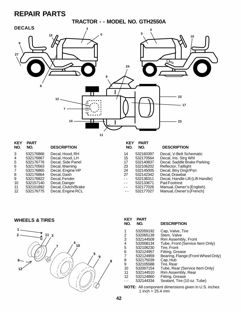
42
REPAIR PARTSTRACTOR - - MODEL NO. GTH2550A
WHEELS & TIRES
6
12
2
1
311
410
59
8
7
9
8
4
10
6
17
24
3 532176866 Decal, Hood, RH4 532176867 Decal, Hood, LH5 532176776 Decal, Side Panel6 532170563 Decal, Warning7 532176865 Decal, Engine HP8 532176864 Decal, Dash9 532176822 Decal, Fender10 532157140 Decal, Danger11 532101892 Decal, Clutch/Brake12 532176775 Decal, Engine RCL
14 532160397 Decal, V-Belt Schematic15 532170564 Decal, Ins. Strg Whl17 532140837 Decal, Saddle Brake Parking23 532106202 Reflector, Taillight24 532145005 Decal, Btry Dngr/Psn27 532142342 Decal, Drawbar- - 532138311 Decal, Handle Lift (Lift Handle)- - 532133671 Pad Footrest- - 532177026 Manual, Owner’s (English) - - 532177027 Manual, Owner’s (French)
KEY PARTNO. NO. DESCRIPTION
KEY PARTNO. NO. DESCRIPTION
KEY PARTNO. NO. DESCRIPTION
1 532059192 Cap, Valve, Tire2 532065139 Stem, Valve3 532144509 Rim Assembly, Front4 532008134 Tube, Front (Service Item Only)5 532106230 Tire, Front6 532124957 Fitting, Grease7 532124959 Bearing, Flange (Front Wheel Only)8 532175039 Cap, Hub9 532105588 Tire, Rear10 532007154 Tube, Rear (Service Item Only)11 532144510 Rim Assembly, Rear12 532124860 Fitting, Grease- - 532144334 Sealant, Tire (10 oz. Tube)
14
NOTE: All component dimensions given in U.S. inches 1 inch = 25.4 mm
15
3
1223
23
7
11
DECALS
27
5 5
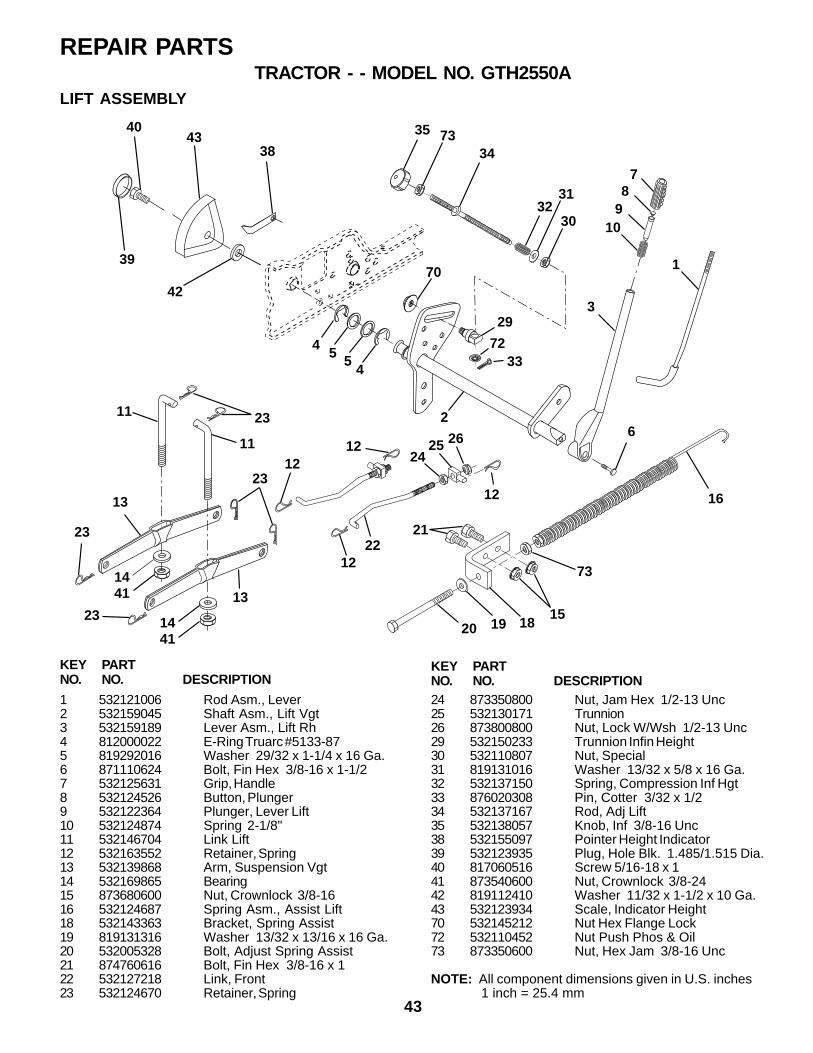
43
REPAIR PARTSTRACTOR - - MODEL NO. GTH2550A
1 532121006 Rod Asm., Lever2 532159045 Shaft Asm., Lift Vgt3 532159189 Lever Asm., Lift Rh4 812000022 E-Ring Truarc #5133-875 819292016 Washer 29/32 x 1-1/4 x 16 Ga.6 871110624 Bolt, Fin Hex 3/8-16 x 1-1/27 532125631 Grip, Handle8 532124526 Button, Plunger9 532122364 Plunger, Lever Lift10 532124874 Spring 2-1/8"11 532146704 Link Lift12 532163552 Retainer, Spring13 532139868 Arm, Suspension Vgt14 532169865 Bearing15 873680600 Nut, Crownlock 3/8-1616 532124687 Spring Asm., Assist Lift18 532143363 Bracket, Spring Assist19 819131316 Washer 13/32 x 13/16 x 16 Ga.20 532005328 Bolt, Adjust Spring Assist21 874760616 Bolt, Fin Hex 3/8-16 x 122 532127218 Link, Front23 532124670 Retainer, Spring
KEY PARTNO. NO. DESCRIPTION
35 7334
3231
30
4 5 54
2
11
11
78
910
3
6
1
1441
1441
12
13
13
21
192015
73
16
262524
22
2312
12
12
23
23
23
18
38
42
39
4043
29
70
3372
LIFT ASSEMBLY
KEY PARTNO. NO. DESCRIPTION24 873350800 Nut, Jam Hex 1/2-13 Unc25 532130171 Trunnion26 873800800 Nut, Lock W/Wsh 1/2-13 Unc29 532150233 Trunnion Infin Height30 532110807 Nut, Special31 819131016 Washer 13/32 x 5/8 x 16 Ga.32 532137150 Spring, Compression Inf Hgt33 876020308 Pin, Cotter 3/32 x 1/234 532137167 Rod, Adj Lift35 532138057 Knob, Inf 3/8-16 Unc38 532155097 Pointer Height Indicator39 532123935 Plug, Hole Blk. 1.485/1.515 Dia.40 817060516 Screw 5/16-18 x 141 873540600 Nut, Crownlock 3/8-2442 819112410 Washer 11/32 x 1-1/2 x 10 Ga.43 532123934 Scale, Indicator Height70 532145212 Nut Hex Flange Lock72 532110452 Nut Push Phos & Oil73 873350600 Nut, Hex Jam 3/8-16 Unc
NOTE: All component dimensions given in U.S. inches 1 inch = 25.4 mm
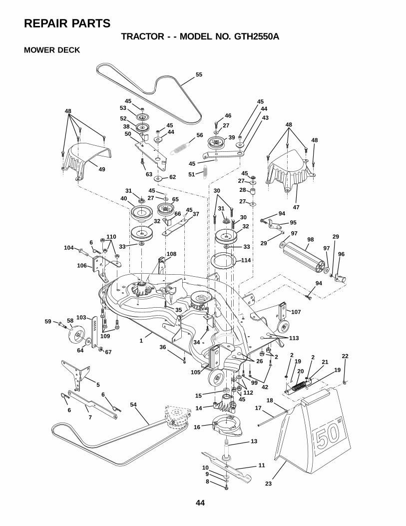
44
REPAIR PARTSTRACTOR - - MODEL NO. GTH2550A
55
46
27
39
4544
434544
51
45
56
48
48
4553
523850
48
4963
47
4527
28
2731
30
30
32
33
114
4527
31 40
3266 37
33
65
5
6
67
54
34
35
36
4299
113
26
4515
14
16
13
111098
219
20
2
1921
22
1817
23
1
45
62
104
106
107
105
108
103
67
59
6110
58
109
64
94
95
9798
97
29
96
29
94
2
112
MOWER DECK
45
REPAIR PARTSTRACTOR - - MODEL NO. GTH2550A
KEY PARTNO. NO. DESCRIPTION
KEY PARTNO. NO. DESCRIPTION
1 532178897 Deck Asm., Mower 50"2 873680500 Nut, Crownlock 5/16-185 532138457 Bracket Asm., Sway Bar6 532124670 Retainer, Spring7 532130832 Arm Suspension, Rear8 532850857 Bolt 3/8-24 x 1.25 Gr. 8 Patched9 810030600 Washer, Lock Hvy 3/8 Unplated10 532140296 Washer, Hard Blade Mower Vented11 532137380 Blade (3 Required)13 532137553 Shaft Asm., W/Lower Brg14 532137152 Housing, Mandrel 50" Vent15 532110485 Bearing, Ball Mandrel16 532174493 Stripper, Mower17 532106735 Rod, Hinge18 819111016 Washer 11/32 x 5/8 x 16 Ga.19 532105304 Cap Sleeve20 532123713 Spring, Torison Delector21 532137607 Bracket, Deflector22 532110452 Nut, Push23 532171593 Shield, Deflector Mower26 872110606 Bolt RdHd Sht Sqnk27 819131316 Washer 13/32 x 13/16 x 16 Ga.28 532132823 Spacer, Spring Stop Idler29 873800600 Nut, Lock Hex W/Wsh 3/8-16 Unc30 532157722 Screw Thd Rolling Washer Head31 532137266 Nut, Flg Top Lock Cntr 9/1632 532153535 Pulley, Mandrel33 532129963 Washer, Spacer Mower Vented34 872140610 Bolt, Carriage 3/8-16 x 1-1/435 872110616 Bolt, Carriage 3/8-16 x 236 872110608 Bolt, Carriage 3/8-16 x 1 Gr. 537 532137166 Stiffener, Arm Idler38 532156085 Keeper, Belt Idler39 532131494 Pulley, Idler Flat40 532136572 Pulley, Driven42 872140506 Bolt, Carriage 5/16-18 Unc x 3/443 532136460 Arm, Idler Secondary44 532165723 Spacer, Retainer45 873680600 Nut, Crownlock 3/8-16 Unc46 874760628 Bolt, Fin Hex 3/8-16 Unc x 1-3/447 532137200 Cover, Mandrel RH
48 532137729 Screw, Thd Roll 1/4-20 x 5/849 532136574 Cover, Mandrel LH50 532137272 Arm, Idler Primary51 532137273 Spring, Secondary52 532139245 Pulley, Idler V Groove53 532137789 Shield, Idler54 532139573 V-Belt, Mower Primary55 532144959 V-Belt, Mower Secondary56 532138687 Spring, Primary58 532133957 Wheel, Gauge59 532137644 Bolt, Shoulder62 532133943 Washer Hardened63 872110612 Bolt Carriage 3/8-16 x 1-1/264 819121414 Washer 3/8 x 7/8 x 14 Ga.65 532151831 Pulley Idler Flat Mower66 532156009 Keeper, Belt Idler 50" Vent67 873930600 Nut, Center Lock 3/8-1694 874760616 Bolt H 3/8-16 x 195 532132274 Bracket, Asm. Noseroller LH96 532132273 Bracket, Asm. Noseroller RH97 819171416 Washer 17/32 x 7/8 x 16 Ga.98 532132264 Roller, Nose99 872110614 Bolt, Carriage 3/8-16 x 1-3/4 Gr. 5103 532155986 Bar Adj. Gauge Wh.104 532156941 Pin Head Rivot105 532156852 Bracket Ga Wh Asm RH 50106 532156853 Bracket Ga Wh Asm LH 50107 532156854 Bracket Ga Wh Assy F RH 50108 532156856 Bracket Ga Wh Assy F LH 50109 872010505 Bolt Carraige 5/16- 18 x 5/8110 873980500 Nut Crownlock 5/16-18112 819171216 Washer 17/32 x 3/4 x 16 Ga.113 872110504 Bolt Carriage 5/16-Unc 1/2114 532153183 Reinforcement Mandrel Ring- - 532143651 Mandrel Asm (Includes Key Nos. 8-
10, 13-15, 31 and 33)- - 532178346 Mower Asm Service (Std. Deck -
Order separately all Nose Rollercomponents)
NOTE: All component dimensions given in U.S. inches1 inch = 25.4 mm
MOWER DECK
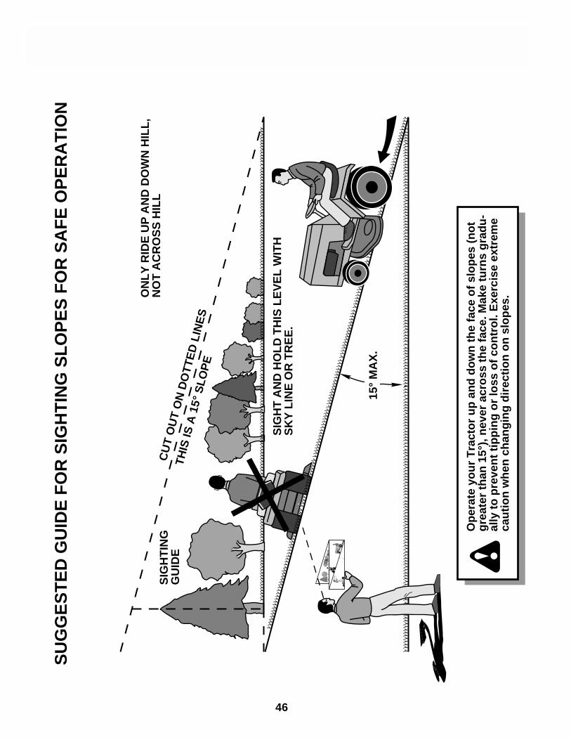
46
REPAIR PARTSTRACTOR - - MODEL NO. GTH2550A
15°
MA
X.
SIG
HT
AN
D H
OL
D T
HIS
LE
VE
L W
ITH
SK
Y L
INE
OR
TR
EE
.
CU
T O
UT
ON
DO
TTE
D L
INE
S
THIS
IS A
15°
SLO
PE
SIG
HT
ING
G
UID
E
ON
LY
RID
E U
P A
ND
DO
WN
HIL
L,
NO
T A
CR
OS
S H
ILL
SU
GG
ES
TE
D G
UID
E F
OR
SIG
HT
ING
SL
OP
ES
FO
R S
AF
E O
PE
RA
TIO
N
Op
erat
e yo
ur
Tra
cto
r u
p a
nd
do
wn
th
e fa
ce o
f sl
op
es (
no
tg
reat
er t
han
15°
), n
ever
acr
oss
th
e fa
ce. M
ake
turn
s g
rad
u-
ally
to
pre
ven
t ti
pp
ing
or
loss
of
con
tro
l. E
xerc
ise
extr
eme
cau
tio
n w
hen
ch
ang
ing
dir
ecti
on
on
slo
pes
.

47
REPAIR PARTSTRACTOR - - MODEL NO. GTH2550A
WA
RR
AN
TY S
TATE
ME
NT
SE
CT
ION
1: L
IMIT
ED
WA
RR
AN
TY
Hus
qvar
na F
ores
t &
Gar
den
Com
pany
(“H
usqv
arna
”) w
arra
nts
Hus
qvar
na p
rodu
ct t
o th
e or
igin
alpu
rcha
ser
to b
e fr
ee f
rom
def
ects
in m
ater
ial a
nd w
orkm
ansh
ip f
rom
the
dat
e of
pur
chas
e fo
r th
e“W
arra
nty
Per
iod”
of
the
prod
uct
as s
et f
orth
bel
ow:
Life
time
War
ran
ty: A
ll til
ler t
ines
, trim
mer
sha
fts, i
gniti
on c
oils
and
mod
ules
on
hand
hel
d pr
oduc
t.
2-Y
ear W
arra
nty
: Rid
ing
law
n m
ower
s, y
ard
and
gard
en tr
acto
rs, w
alk
behi
nd m
ower
s, ti
llers
, cha
insa
ws,
trim
mer
s, b
rush
cutte
rs, c
lear
ing
saw
s, s
now
blo
wer
s, h
andh
eld
blow
ers,
bac
kpac
k bl
ower
s,he
dge
trim
mer
s,
and
elec
tric
al p
rodu
cts
for
nonc
omm
erci
al,
nonp
rofe
ssio
nal,
non-
inst
itutio
nal o
rno
n-in
com
e pr
oduc
ing
use,
exc
ept
as h
erei
n st
ated
. E
mis
sion
con
trol
sys
tem
com
pone
nts
nece
ssar
y to
com
ply
with
CA
RB
-95
and
EP
A r
egul
atio
ns, e
xcep
t for
thos
e co
mpo
nent
s w
hich
are
part
of e
ngin
e sy
stem
s m
anuf
actu
red
by th
ird p
arty
eng
ine
man
ufac
ture
rs fo
r w
hich
the
purc
hase
rha
s re
ceiv
ed a
sep
arat
e w
arra
nty
with
pro
duct
info
rmat
ion
supp
lied
at t
ime
of p
urch
ase.
1-Y
ear
War
ran
ty:
Pow
er c
utte
rs,
stum
p gr
inde
r, h
ydra
ulic
pol
e pr
uner
s an
d hy
drau
lic p
ole
saw
sfo
r non
-com
mer
cial
, non
-pro
fess
iona
l, no
n-in
stitu
tiona
l or n
on-in
com
e pr
oduc
ing
use.
All
trim
mer
s,br
ushc
utte
rs,
clea
ring
saw
s, h
over
ing
trim
mer
s, s
tick
edge
rs,
back
pack
blo
wer
s, h
and
held
blow
ers,
hed
ge tr
imm
ers
and
mod
el s
erie
s 58
0 &
600
wal
k-be
hind
mow
ers
used
for
com
mer
cial
,in
stitu
tion-
al,
prof
essi
onal
or
inco
me
prod
ucin
g pu
rpos
es o
r us
e.
90-D
ay W
arra
nty
: C
hain
saw
s, p
ower
cut
ters
, st
ump
grin
ders
, tr
imm
ers,
bru
shcu
tters
, cl
earin
gsa
ws,
hov
erin
g tr
imm
ers,
stic
k ed
gers
, he
dge
trim
mer
s, b
ackp
ack
blow
ers,
han
d he
ld b
low
ers,
hydr
aulic
pol
e sa
ws,
hyd
raul
ic p
ole
prun
ers,
sno
w t
hrow
ers
or a
ny H
usqv
arna
pro
duct
use
d fo
rre
ntal
pur
pose
s or
use
exc
ept
as o
ther
wis
e pr
ovid
ed h
erei
n.
30 D
ay W
arra
nty
: Hus
qvar
na b
ow g
uide
bar
s, re
plac
emen
t par
ts in
clud
ing
bar a
nd c
hain
s, p
rodu
ctac
cess
orie
s, t
ools
, di
spla
y fe
atur
es a
nd s
afet
y ap
pare
l.
SE
CT
ION
2: H
US
QV
AR
NA
’S O
BL
IGA
TIO
NS
UN
DE
R T
HE
WA
RR
AN
TY
Hus
qvar
na w
ill r
epai
r or
rep
lace
def
ectiv
e co
mpo
nent
s w
ithou
t ch
arge
for
par
ts o
r la
bor
if a
com
pone
nt f
ails
bec
ause
of
a de
fect
in m
ater
ial o
r w
orkm
ansh
ip d
urin
g th
e w
arra
nty
perio
d.
SE
CT
ION
3: I
TE
MS
NO
T C
OV
ER
ED
BY
TH
IS W
AR
RA
NT
YT
he f
ollo
win
g ite
ms
are
not
cove
red
by t
his
war
rant
y:
(1) N
orm
al c
usto
mer
mai
nten
ance
item
s w
hich
bec
ome
wor
n th
roug
h no
rmal
regu
lar u
se, i
nclu
ding
,bu
t not
lim
ited
to, b
elts
, bla
des,
bla
de a
dapt
ers,
bul
bs, f
ilter
s, g
uide
bar
s, lu
bric
ants
, rew
ind
sprin
gs,
saw
cha
in,
spar
k pl
ugs,
sta
rter
rop
es a
nd t
ines
;
(2)
Nat
ural
dis
colo
ratio
n of
mat
eria
l due
to u
ltrav
iole
t lig
ht;
(3)
Eng
ine
and
driv
e sy
stem
s no
t m
anuf
actu
red
by H
usqv
arna
; th
ese
item
s ar
e co
vere
d by
the
resp
ectiv
e m
anuf
actu
rer’s
war
rant
y as
pro
vide
d in
writ
ing
with
the
prod
uct i
nfor
mat
ion
supp
lied
atth
e tim
e of
pur
chas
e;
all c
laim
s m
ust
be s
ent
to t
he a
ppro
pria
te m
anuf
actu
rer;
(4)
Law
n an
d ga
rden
atta
chm
ents
are
cov
ered
by
a th
ird p
arty
that
giv
es a
war
rant
y, a
ll cl
aim
s fo
rw
arra
nty
shou
ld b
e se
nt t
o th
e m
anuf
actu
rer;
and
(5) E
mis
sion
Con
trol
Sys
tem
com
pone
nts
nece
ssar
y to
com
ply
with
CA
RB
-95
and
EP
A re
gula
tions
whi
ch a
re m
anuf
actu
red
by t
hird
par
ty e
ngin
e m
anuf
actu
rer.
(6)
Bat
terie
s ha
ve a
one
-yea
r pr
orat
ed li
mite
d w
arra
nty
with
100
% r
epla
cem
ent
durin
g th
e fir
st 6
mon
ths.
SE
CT
ION
4: E
XC
EP
TIO
NS
AN
D L
IMIT
AT
ION
ST
his
war
rant
y sh
all b
e in
appl
icab
le t
o de
fect
s re
sulti
ng f
rom
the
fol
low
ing:
(1) A
ccid
ent,
abus
e, m
isus
e, n
eglig
ence
and
neg
lect
, inc
ludi
ng s
tale
fuel
, dirt
, abr
asiv
es, m
oist
ure,
rust
,co
rros
ion,
or
any
adve
rse
reac
tion
due
to i
ncor
rect
sto
rage
or
use
habi
ts;
(2) F
ailu
re to
ope
rate
or m
aint
ain
the
unit
in a
ccor
danc
e w
ith th
e O
wne
r’s/O
pera
tor’s
man
ual o
r ins
truc
tion
shee
t fu
rnis
hed
by H
usqv
arna
;
(3)
Alte
ratio
ns o
r m
odifi
catio
ns t
hat
chan
ge t
he i
nten
ded
use
of t
he p
rodu
ct o
r af
fect
s th
e pr
oduc
t’spe
rfor
man
ce, o
pera
tion,
saf
ety,
or d
urab
ility
, or c
ause
s th
e pr
oduc
t to
fail
to c
ompl
y w
ith a
ny a
pplic
able
law
s; o
r:
(4)
Add
ition
al d
amag
e to
par
ts o
r co
mpo
nent
s du
e to
con
tinue
d us
e oc
curr
ing
afte
r an
y of
the
abov
e.
RE
PA
IR O
R R
EP
LAC
EM
EN
T A
S P
RO
VID
ED
UN
DE
R T
HIS
WA
RR
AN
TY
IS
TH
E E
XC
LUS
IVE
RE
ME
DY
OF
TH
E P
UR
CH
AS
ER
. HU
SQ
VA
RN
A S
HA
LL N
OT
BE
LIA
BLE
FO
R A
NY
INC
IDE
NT
AL
OR
CO
NS
E-Q
UE
NT
IAL
DA
MA
GE
S F
OR
BR
EA
CH
OF
AN
Y E
XP
RE
SS
OR
IM
PLI
ED
WA
RR
AN
TY
ON
TH
ES
E P
RO
D-U
CT
S E
XC
EP
T T
O T
HE
EX
TE
NT
PR
OH
IBIT
ED
BY
AP
PLI
CA
BLE
LA
W. A
NY
IMP
LIE
DW
AR
RA
NT
Y O
F M
ER
CH
AN
TA
BIL
ITY
OR
FIT
NE
SS
FO
R A
PA
RT
ICU
LAR
PU
RP
OS
E O
N T
HE
SE
PR
OD
UC
TS
IS
LIM
IT-E
D I
N D
UR
AT
ION
TO
TH
E W
AR
RA
NT
Y P
ER
IOD
AS
DE
FIN
ED
IN
TH
ELI
MIT
ED
WA
RR
AN
TY
ST
AT
E-M
EN
T.
HU
SQ
VA
RN
A R
ES
ER
VE
S T
HE
RIG
HT
TO
CH
AN
GE
OR
IM
PR
OV
E T
HE
DE
SIG
N O
F T
HE
PR
OD
UC
T W
ITH
OU
T N
OT
ICE
, A
ND
DO
ES
NO
T A
SS
UM
E O
BLI
GA
TIO
N T
O U
PD
AT
E P
RE
VI-
OU
SLY
MA
NU
FA
CT
UR
ED
PR
OD
UC
TS
.
Som
e st
ates
do
not a
llow
the
excl
usio
n of
inci
dent
al o
r co
nseq
uent
ial d
amag
es, o
r lim
itatio
ns o
n ho
wlo
ng a
n im
plie
d w
arra
nty
last
s, s
o th
e ab
ove
limita
tions
or e
xclu
sion
s m
ay n
ot a
pply
to y
ou. T
his
war
rant
ygi
ves
you
spec
ific
lega
l rig
hts,
and
you
may
als
o ha
ve o
ther
rig
hts
whi
ch v
ary
from
sta
te t
o st
ate.
SE
CT
ION
5: C
US
TO
ME
R R
ES
PO
NS
IBIL
ITIE
ST
he p
rodu
ct m
ust e
xhib
it re
ason
able
car
e, m
aint
enan
ce, o
pera
tion,
sto
rage
and
gen
eral
upk
eep
as w
rit-
ten
in t
he m
aint
enan
ce s
ectio
n of
the
Ow
ner’s
/Ope
rato
r’s m
anua
l. S
houl
d an
ope
ratio
nal p
robl
em o
rfa
ilure
occ
ur,
the
prod
uct
shou
ld n
ot b
e us
ed,
but
deliv
ered
as
is t
o an
aut
horiz
ed H
usqv
arna
dea
ler
for
eval
uatio
n. P
roof
of
purc
hase
, as
exp
lain
ed in
sec
tion
6, r
ests
sol
ely
with
the
cus
tom
er.
SE
CT
ION
6: P
RO
CE
DU
RE
TO
OB
TA
IN W
AR
RA
NT
Y C
ON
SID
ER
AT
ION
It is
the
Ow
ner’s
and
Dea
ler’s
res
pons
ibili
ty t
o m
ake
cert
ain
that
the
War
rant
y R
egis
trat
ion
Car
d is
prop
erly
fille
d ou
t and
mai
led
to H
usqv
arna
For
est &
Gar
den
Com
pany
. Thi
s ca
rd s
houl
d be
mai
led
with
inte
n (1
0) d
ays
from
the
date
of p
urch
ase
in o
rder
to c
onfir
m th
e w
arra
nty
and
to fa
cilit
ate
post
-sal
e se
rvic
e.P
roof
of
purc
hase
mus
t be
pre
sent
ed t
o th
e au
thor
ized
Hus
qvar
na d
eale
r in
ord
er t
o ob
tain
war
rant
yse
rvic
e. T
his
proo
f m
ust
incl
ude
date
pur
chas
ed,
mod
el n
umbe
r, s
eria
l num
ber,
and
com
plet
e na
me
and
addr
ess
of th
e se
lling
dea
ler.
To
obta
in th
e be
nefit
of t
his
war
rant
y, th
e pr
oduc
t bel
ieve
d to
be
defe
ctiv
em
ust b
e de
liver
ed to
an
auth
oriz
ed H
usqv
arna
dea
ler
in a
tim
ely
man
ner,
no
late
r th
an th
irty
(30)
day
sfr
om d
ate
of th
e op
erat
iona
l pro
blem
or
failu
re. T
he p
rodu
ct m
ust b
e de
liver
ed a
t the
ow
ner’s
exp
ense
.P
ick-
up a
nd d
eliv
ery
char
ges
are
not
cove
red
by t
his
war
rant
y. A
n au
thor
ized
Hus
qvar
na d
eale
r ca
nbe
nor
mal
ly lo
cate
d th
roug
h th
e “Y
ello
w P
ages
” of
the
loca
l tel
epho
ne d
irect
ory
or b
y ca
lling
1-8
00-
HU
SK
Y62
for
a d
eale
r in
you
r ar
ea.
HU
SQ
VA
RN
A90
06 P
ER
IME
TE
R W
OO
DS
DR
IVE
CH
AR
LO
TT
E,
NC
282
1653
1 83
81-
23 1
1/99

532177026 1.10.01 JH Printed in U.S.A.