Embed Size (px)
Citation preview
Operator’s Manualwith Maintenance Information
First Edition
Fourth Printing
Part No. 62756

Genie S-120 & Genie S-125 Part No. 62756
Operator's Manual First Edition • Fourth Printing
Copyright © 2000 by Genie Industries
First Edition: First Printing, May 2000Second Printing, July 2000Third Printing, July 2000Fourth Printing, January 2001
"Genie" is a registered trademark ofGenie Industries in the U.S.A. and many othercountries. "S" is a trademark of Genie Industries.
These machines comply withANSI/SIA 92.5-1992.
Printed on recycled paper
Printed in U.S.A.
®
Important
Read, understand and obey these safety rules andoperating instructions before operating this machine.Only trained and authorized personnel shall bepermitted to operate this machine. This manual shouldbe considered a permanent part of your machine andshould remain with the machine at all times. If youhave any questions, call Genie Industries.
Contents
PageSafety Rules .............................................................. 1Controls ..................................................................... 7Pre-operation Inspection........................................... 10Maintenance ............................................................. 12Function Tests .......................................................... 15Work Place Inspection .............................................. 21Operating Instructions .............................................. 22Transport .................................................................. 26Decals ...................................................................... 27Specifications ........................................................... 29
Contact us:
Internet: http://www.genielift.comE-mail: [email protected]

Part No. 62756 Genie S-120 & Genie S-125 1
Operator's ManualFirst Edition · Fourth Printing
Safety Rules
Danger
Failure to obey the instructions andsafety rules in this manual will resultin death or serious injury.
Do Not Operate Unless:
You learn and practice the principles of safemachine operation contained in this operator'smanual.
1 Avoid hazardous situations.
Know and understand the above principlebefore going on to the next section.
2 Always perform a pre-operation inspection.
3 Always perform function tests prior to use.
4 Inspect the work place.
5 Only use the machine as it was intended.
You read, understand and obey:
Manufacturer's instructions and safetyrules—safety and operator's manualsand machine decals
employer's safety rules and worksiteregulations
applicable governmental regulations
You are properly trained to safely operate themachine.

2 Genie S-120 & Genie S-125 Part No. 62756
Operator's Manual First Edition · Fourth Printing
SAFETY RULES
Electrocution Hazards
This machine is not electrically insulated and willnot provide protection from contact with orproximity to electrical current.
Maintain safe distances from electrical power linesand apparatus in accordance with applicablegovernmental regulations and the following chart.
Voltage Minimum SafePhase to Phase Approach Distance
Feet Meters
0 to 300V Avoid Contact
300V to 50KV 10 3.05
50KV to 200KV 15 4.60
200KV to 350KV 20 6.10
350KV to 500KV 25 7.62
500KV to 750KV 35 10.67
750KV to 1000KV 45 13.72
Allow for platform movement, electrical line swayor sag and beware of strong or gusty winds.
Keep away from the machine if it contactsenergized power lines. Personnel on the ground orin the platform must not touch or operate themachine until energized power lines are shut off.
Do not use the machine as a ground for weldingunless the machine is equipped with the weld lineto platform option and it is properly connected.
Tip-over Hazards
Occupants and equipment shall not exceed themaximum platform capacity.
Maximum platform capacityS-120 750 lbs 340 kgS-125 500 lbs 227 kg
Maximum occupants 2
Do not raise or extend the boom unless themachine is on a firm, level surface.
Do not depend on the tilt alarm as a level indicator.The tilt alarm sounds in the platform only when themachine is on a severe slope.
Part No. 62756 Genie S-120 & Genie S-125 3
Operator's ManualFirst Edition · Fourth Printing
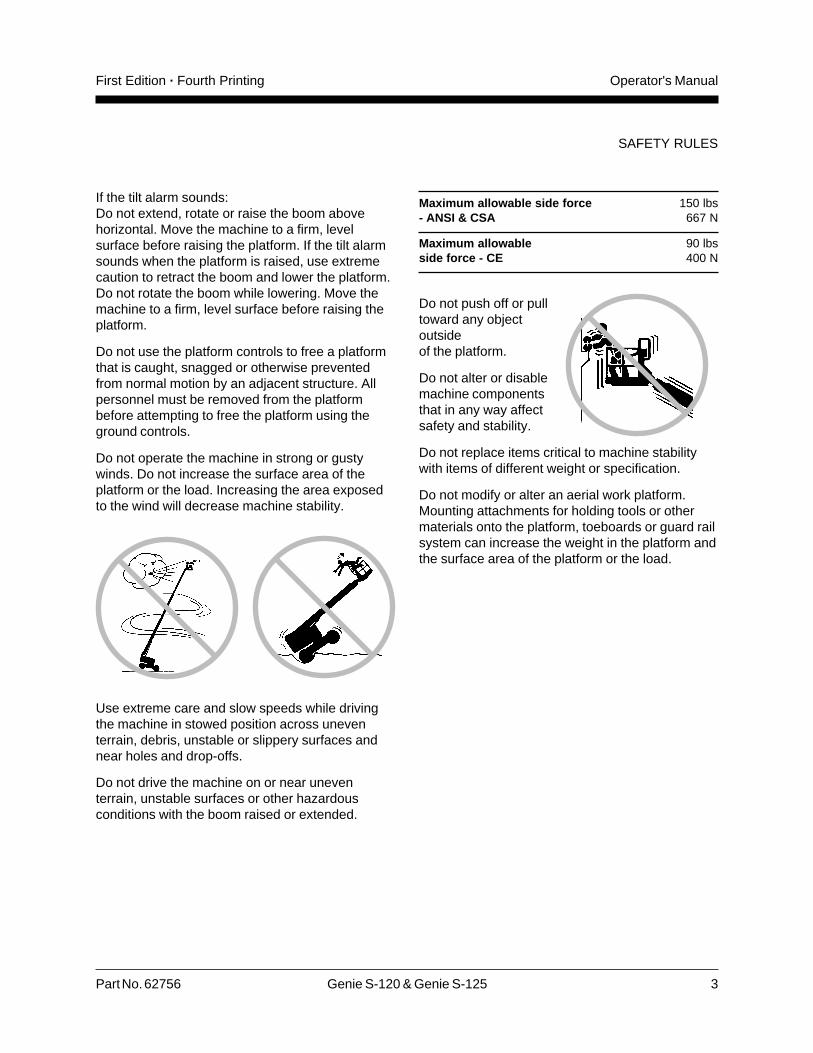
If the tilt alarm sounds:Do not extend, rotate or raise the boom abovehorizontal. Move the machine to a firm, levelsurface before raising the platform. If the tilt alarmsounds when the platform is raised, use extremecaution to retract the boom and lower the platform.Do not rotate the boom while lowering. Move themachine to a firm, level surface before raising theplatform.
Do not use the platform controls to free a platformthat is caught, snagged or otherwise preventedfrom normal motion by an adjacent structure. Allpersonnel must be removed from the platformbefore attempting to free the platform using theground controls.
Do not operate the machine in strong or gustywinds. Do not increase the surface area of theplatform or the load. Increasing the area exposedto the wind will decrease machine stability.
Use extreme care and slow speeds while drivingthe machine in stowed position across uneventerrain, debris, unstable or slippery surfaces andnear holes and drop-offs.
Do not drive the machine on or near uneventerrain, unstable surfaces or other hazardousconditions with the boom raised or extended.
Maximum allowable side force 150 lbs- ANSI & CSA 667 N
Maximum allowable 90 lbsside force - CE 400 N
Do not push off or pulltoward any objectoutsideof the platform.
Do not alter or disablemachine componentsthat in any way affectsafety and stability.
Do not replace items critical to machine stabilitywith items of different weight or specification.
Do not modify or alter an aerial work platform.Mounting attachments for holding tools or othermaterials onto the platform, toeboards or guard railsystem can increase the weight in the platform andthe surface area of the platform or the load.
SAFETY RULES

4 Genie S-120 & Genie S-125 Part No. 62756
Operator's Manual First Edition · Fourth Printing
Do not place or attach overhanging loads to anypart of this machine.
Do not place ladders or scaffolds in the platform oragainst any part of this machine.
Do not use the machine on a moving or mobilesurface or vehicle.
Be sure all tires are in good condition and lug nutsare properly tightened.
Fall Hazards
Occupants must wear asafety belt or harness inaccordance withgovernmental regulations.Attach the lanyard to theanchorage point provided inthe platform.
It is recommended that operators wear anapproved hard hat when operating the machine.
SAFETY RULES
Do not sit, stand or climb on the platform guardrails. Maintain a firm footing on the platform floorat all times.
Do not climb down from the platform when raised.
Keep the platform floor clear of debris.
Lower the platform entry mid-rail or close the entrygate before operating.
Collision Hazards
Be aware of limited sightdistance and blind spotswhen driving or operating.
Be aware of boom position and tailswing whenrotating turntable.
Check work area for overhead obstructions orother possible hazards.
Be aware of crushing hazard when grasping theplatform guard rail.

Part No. 62756 Genie S-120 & Genie S-125 5
Operator's ManualFirst Edition · Fourth Printing
SAFETY RULES
Component Damage Hazards
Do not use any battery or charger greater than 12Vto jump-start the engine.
Do not use the machine as a ground for welding.
Be sure the hydraulic shutoff valves (located byhydraulic tank) are open before starting the engine.
Explosion and Fire Hazards
Do not start the engine if you smell or detect liquidpetroleum gas (LPG), gasoline, diesel fuel or otherexplosive substances.
Do not refuel the machine with the engine running.
Refuel the machine and charge the battery only inan open, well-ventilated area away from sparks,flames and lighted tobacco.
Do not operate the machine in hazardous locationsor locations where potentially flammable orexplosive gases or particles may be present.
Observe and use the circle and square markingsand the color-coded direction arrows on theplatform controls and drive chassis for drive andsteer functions.
Do not lower the boom unless the area below isclear of personnel and obstructions.
Limit travel speed according to the condition ofground surface, congestion, slope, location ofpersonnel, and any other factors which may causecollision.
Do not operate a boom in the path of any craneunless the controls of the crane have been lockedout and/or precautions have been taken to preventany potential collision.
No stunt driving or horseplay while operating amachine.
6 Genie S-120 & Genie S-125 Part No. 62756
Operator's Manual First Edition · Fourth Printing
SAFETY RULES
Decal Legend
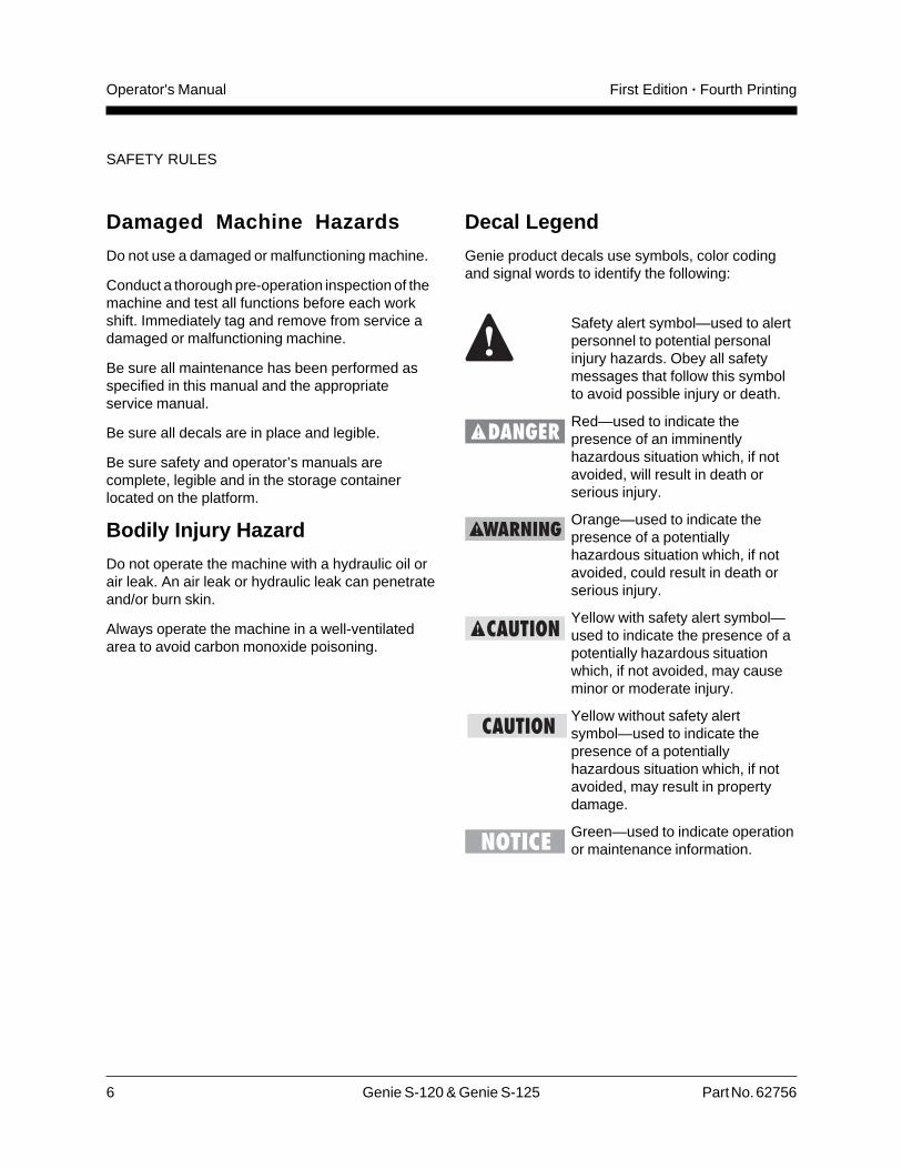
Genie product decals use symbols, color codingand signal words to identify the following:
Safety alert symbol—used to alertpersonnel to potential personalinjury hazards. Obey all safetymessages that follow this symbolto avoid possible injury or death.
Red—used to indicate thepresence of an imminentlyhazardous situation which, if notavoided, will result in death orserious injury.
Orange—used to indicate thepresence of a potentiallyhazardous situation which, if notavoided, could result in death orserious injury.
Yellow with safety alert symbol—used to indicate the presence of apotentially hazardous situationwhich, if not avoided, may causeminor or moderate injury.
Yellow without safety alertsymbol—used to indicate thepresence of a potentiallyhazardous situation which, if notavoided, may result in propertydamage.
Green—used to indicate operationor maintenance information.
Damaged Machine Hazards
Do not use a damaged or malfunctioning machine.
Conduct a thorough pre-operation inspection of themachine and test all functions before each workshift. Immediately tag and remove from service adamaged or malfunctioning machine.
Be sure all maintenance has been performed asspecified in this manual and the appropriateservice manual.
Be sure all decals are in place and legible.
Be sure safety and operator’s manuals arecomplete, legible and in the storage containerlocated on the platform.
Bodily Injury Hazard
Do not operate the machine with a hydraulic oil orair leak. An air leak or hydraulic leak can penetrateand/or burn skin.
Always operate the machine in a well-ventilatedarea to avoid carbon monoxide poisoning.

Part No. 62756 Genie S-120 & Genie S-125 7
Operator's ManualFirst Edition · Fourth Printing
Controls
Ground Control Panel
1 Boom down button
2 Boom extend/retract buttons
3 Boom up button
4 Engine speed select button
5 LCD screen control buttons
6 Gasoline/LPG select button
7 LCD readout screen
8 Emergency Stop button
9 Gasoline/LPG models: Choke buttonDeutz Diesel models: Glow plug button
10 Key switch for off/platform/ground selection
11 Engine start button
12 Auxiliary power button
13 High speed function enable button
14 Low speed function enable button
15 Alarm
16 Platform level up/down buttons
17 S-125 models: Jib boom up/down buttons
18 Platform rotate left/right buttons
19 Turntable rotate left/right buttons
8 Genie S-120 & Genie S-125 Part No. 62756
Operator's Manual First Edition · Fourth Printing
CONTROLS
1
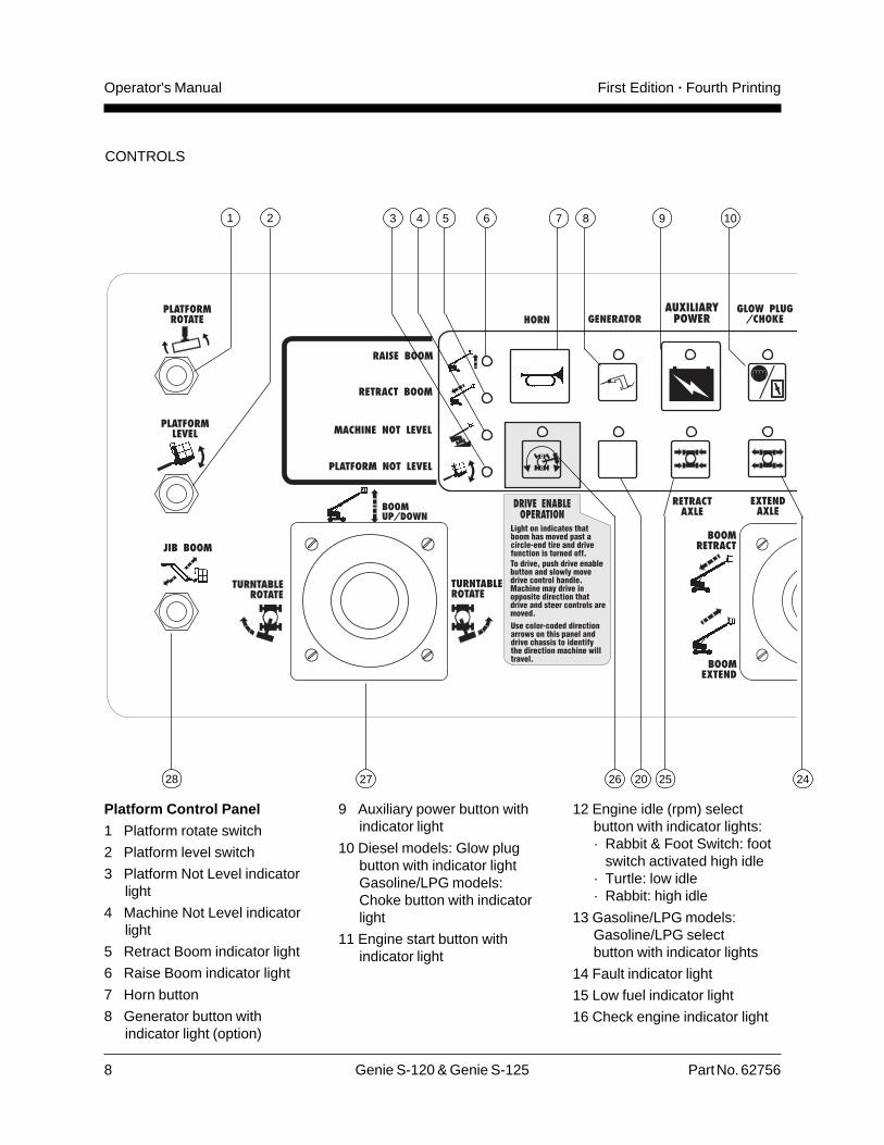
12 Engine idle (rpm) selectbutton with indicator lights:· Rabbit & Foot Switch: foot
switch activated high idle· Turtle: low idle· Rabbit: high idle
13 Gasoline/LPG models:Gasoline/LPG selectbutton with indicator lights
14 Fault indicator light
15 Low fuel indicator light
16 Check engine indicator light
Platform Control Panel
1 Platform rotate switch
2 Platform level switch
3 Platform Not Level indicatorlight
4 Machine Not Level indicatorlight
5 Retract Boom indicator light
6 Raise Boom indicator light
7 Horn button
8 Generator button withindicator light (option)
2 65 7 8 9 10
242520262728
43
9 Auxiliary power button withindicator light
10 Diesel models: Glow plugbutton with indicator lightGasoline/LPG models:Choke button with indicatorlight
11 Engine start button withindicator light

Part No. 62756 Genie S-120 & Genie S-125 9
Operator's ManualFirst Edition · Fourth Printing
CONTROLS
17 Emergency Stop button
18 Power indicator light
19 Dual axis proportional controlhandle for drive and steerfunctionsOR Proportional controlhandle for drive function andthumb rocker for steerfunction
20 Used for optional equipment
21 Steer mode select buttonswith indicator lights
11 12 13 1514 17
19 18
16
20212223
22 Drive select button withindicator lights:Machine on incline symbol:Low rangeoperation for inclinesMachine on level surfacesymbol: High range
operation for maximumdrive speed
23 Single axis proportionalcontrol handle for boomextend/retract function
24 Extend axle button withindicator light
25 Retract axle button withindicator light
26 Drive enable button withindicator light
27 Dual axis proportional controlhandle for boom up/downand turntable rotate left/rightfunctions
28 S-125 models: Jib boom up/down toggle switch
10 Genie S-120 & Genie S-125 Part No. 62756
Operator's Manual First Edition · Fourth Printing
Pre-operation Inspection
Do Not Operate Unless:
You learn and practice the principles of safemachine operation contained in this operator'smanual.
1 Avoid hazardous situations.
2 Always perform a pre-operationinspection.
Know and understand the above principlesbefore going on to the next section.
3 Always perform function tests prior to use.
4 Inspect the work place.
5 Only use the machine as it was intended.
Fundamentals
It is the responsibility of the operator to perform aPre-operation Inspection and routine maintenance.
The Pre-operation Inspection is a visual inspectionperformed by the operator prior to each work shift.The inspection is designed to discover if anythingis apparently wrong with a machine before theoperator performs the function tests.
The Pre-operation Inspection also serves todetermine if routine maintenance procedures arerequired. Only routine maintenance items specifiedin this manual may be performed by the operator.
Refer to the list on the next page and check eachof the items and locations for modifications,damage or loose or missing parts.
A damaged or modified machine must never beused. If damage or any variation from factorydelivered condition is discovered, the machinemust be tagged and removed from service.
Repairs to the machine may only be made by aqualified service technician, according to themanufacturer's specifications. After repairs arecompleted, the operator must perform apre-operation inspection again before going on tothe function tests.
Scheduled maintenance inspections shall beperformed by qualified service technicians,according to the manufacturer's specifications andthe requirements listed in the responsibilitiesmanual.

Part No. 62756 Genie S-120 & Genie S-125 11
Operator's ManualFirst Edition · Fourth Printing
PRE-OPERATION INSPECTION
Pre-operation Inspection
� Be sure that the operator’s, safety andresponsibilities manuals are complete, legibleand in the storage container located in theplatform.
� Be sure that all decals are legible and in place.See Decals section.
� Check for engine oil leaks and proper oil level.Add oil if needed. See Maintenance section.
� Check for hydraulic oil leaks and proper oil level.Add oil if needed. See Maintenance section.
� Check for engine coolant leaks and proper levelof coolant. Add coolant if needed. SeeMaintenance section.
� Check for battery fluid leaks and proper fluidlevel. Add distilled water if needed. SeeMaintenance section.
Check the following components or areas fordamage and improperly installed, loose ormissing parts:
� Electrical components, wiring andelectrical cables
� Hydraulic hoses, fittings, cylinders andmanifolds
� Fuel and hydraulic tanks
� Drive and turntable motors and drive hubs
� Boom and axle wear pads
� Tires and wheels
� Engine and related components
� Limit switches and horn
� Alarms and beacons (if equipped)
� Nuts, bolts and other fasteners
� Platform entry mid-rail or gate
Check entire machine for:
� Crack in welds or structural components
� Dents or damage to machine
� Be sure that all structural and other criticalcomponents are present and all associatedfasteners and pins are in place and properlytightened.
� After you complete your inspection, be sure thatall compartment covers are in place andlatched.

12 Genie S-120 & Genie S-125 Part No. 62756
Operator's Manual First Edition · Fourth Printing
Maintenance
Observe and Obey:
Only routine maintenance items specified in thismanual shall be performed by the operator.
Scheduled maintenance inspections shall becompleted by qualified service technicians,according to the manufacturer's specificationsand the requirements specified in theresponsibilities manual.
Maintenance Symbols Legend
The following symbols have beenused in this manual to helpcommunicate the intent of theinstructions. When one or more ofthe symbols appear at thebeginning of a maintenanceprocedure, it conveys the meaningbelow.
Indicates that tools will be required toperform this procedure.
Indicates that new parts will berequired to perform this procedure.
Indicates that a cold engine is requiredbefore performing this procedure.
Check the Engine Oil Level
Maintaining the proper engine oil level is essentialto good engine performance and service life.Operating the machine with an improper oil levelcan damage engine components.
Check the oil level with theengine off.
1 Check the engine oil dipstick. Add oil asneeded.
Cummins models:Result: The oil level should be within the "L" and"H" marks on the dipstick.
Deutz models:Result: The oil level should be within the twomarks on the dipstick.
Perkins models:Result: The oil level should be within the twonotches on the dipstick.
Cummins B3.9L Engine 11.5 quartsOil capacity (including filter) 10.9 liters
Cummins B3.9L EngineOil viscosity requirements
below 68°F / 20°C 5W-30
-10° to 68°F / -23° to 20°C 10W-30
above 15°F / -9°C 15W-40
Use oils meeting API classification CE (labeled CE/SG).
Deutz F4L 913 Engine 14 quartsOil capacity (including filter) 13.5 liters
Deutz F4L 913 Engine Oil viscosityrequirements
below 60°F / 15.5°C (synthetic) 5W-30
-10°F to 90°F / -23°C to 32°C 10W-40
above -4°F / -34°C 15W-40
Engine oil should have properties of API classificationCC/SE or CC/SF grades.

Part No. 62756 Genie S-120 & Genie S-125 13
Operator's ManualFirst Edition · Fourth Printing
MAINTENANCE
Check the Batteries
Proper battery condition is essential to good engineperformance and operational safety. Improper fluidlevels or damaged cables and connections canresult in engine component damage and hazardousconditions.
Electrocution hazard. Contact withhot or live circuits may result indeath or serious injury. Remove allrings, watches and other jewelry.
Bodily injury hazard. Batteriescontain acid. Avoid spilling orcontacting battery acid. Neutralizebattery acid spills with baking sodaand water.
1 Put on protective clothing and eye wear.
2 Be sure that the battery cable connections arefree of corrosion.
3 Be sure that the battery hold downs and cableconnections are tight.
4 Remove the battery vent caps.
5 Check the battery acid level. If needed,replenish with distilled water to the bottom of thebattery fill tube. Do not overfill.
6 Install the vent caps.
Adding terminal protectors and acorrosion preventative sealant willhelp eliminate corrosion on thebattery terminals and cables.
Perkins 1004-42 Engine 8.9 quartsOil capacity (including filter) 8.4 liters
Perkins 1004-42 Engine Oil viscosityrequirements
below 32°F / 0°C 0W
-13°F to 68°F / -25°C to 20°C 5W-20
10°F to 104°F / -12°C to 40°C 10W-30
14°F to 122°F / -10°C to 50°C 15W-40
above 23°F / -5°C 20W-50
Engine oil should have properties of API classificationCF4 grade.
Check the Hydraulic Oil Level
Maintaining the hydraulic oil at the proper level isessential to machine operation. Improper hydraulicoil levels can damage hydraulic components. Dailychecks allow the inspector to identify changes in oillevel that might indicate the presence of hydraulicsystem problems.
1 Be sure that the boom is in the stowed position,then visually inspect the sight gauge located onthe side of the hydraulic oil tank.
Result: The hydraulic oil level should be withinthe top 2 inches (5 cm) of the sight gauge.
Hydraulic oil specifications
Hydraulic oil type Dexron equivalent
Tank capacity 55 gallons 208 liters
Hydraulic system 65 gallons 246 liters(including tank)

14 Genie S-120 & Genie S-125 Part No. 62756
Operator's Manual First Edition · Fourth Printing
Scheduled MaintenanceThe scheduled maintenance items must becompleted by a person trained and qualified toperform maintenance on this machine according tothe procedures found in the service manual for thismachine.
Inspections and maintenance described belowrequire the qualified entity to record and retainrecords of all inspections and maintenance itemsfor four years.
Machines that have been out of service for morethan three months must receive the quarterlyinspection before placing the machine back intoservice.
Check the Engine Coolant Level- Liquid Cooled Models
Maintaining the engine coolant at the proper level isessential to engine service life. Improper coolantlevel will affect the engine's cooling capability anddamage engine components. Daily checks willallow the inspector to identify changes in coolantlevel that might indicate cooling system problems.
1 Check the fluid level in the coolant recoverytank. Add fluid as needed.
Result: The fluid level should be in theNORMAL range.
Bodily injury hazard. Fluids in theradiator are under pressure andextremely hot. Use caution whenremoving cap and adding fluids.
The Schedule
There are five types of maintenance inspectionsthat must be performed according to a schedule—daily, quarterly, six months, annual, two year. Toaccount for repeated procedures, the ScheduledMaintenance Procedures Section and theMaintenance Inspection Report have been dividedinto five subsections—A, B, C, D and E. Use thefollowing chart to determine which group(s) ofprocedures are required to perform a scheduledinspection.
Inspection Table or Checklist
Daily or every 8 hours A
Quarterly or every 250 hours A + B
Six months or every 500 hours A + B + C
Annual or every 1000 hours A + B + C + D
Two year or every 2000 hours A + B + C + D + E
Maintenance Inspection Report
The maintenance inspection report containschecklists for each type of scheduled inspection.
Make copies of the Maintenance Inspection Reportto use for each inspection. Store completed formsfor three years.
MAINTENANCE

Part No. 62756 Genie S-120 & Genie S-125 15
Operator's ManualFirst Edition · Fourth Printing
Function Tests
Fundamentals
The Function Tests are designed to discover anymalfunctions before the machine is put intoservice. The operator must follow the step-by-stepinstructions to test all machine functions.
A malfunctioning machine must never be used. Ifmalfunctions are discovered, the machine must betagged and removed from service. Repairs to themachine may only be made by a qualified servicetechnician, according to the manufacturer'sspecifications.
After repairs are completed, the operator mustperform a pre-operation inspection and functiontests again before putting the machine into service.
Do Not Operate Unless:
You learn and practice the principles of safemachine operation contained in this operator'smanual.
1 Avoid hazardous situations.
2 Always perform a pre-operationinspection.
3 Always perform function tests prior touse.
Know and understand the above principlesbefore going on to the next section.
4 Inspect the work place.
5 Only use the machine as it was intended.
1 Select a test area that is firm, level and free ofobstruction.
At the Ground Controls2 Turn the key switch to ground control.
3 Pull out the red Emergency Stop button tothe ON position.
Result: The LCD screen will come on anddisplay no error messages. The beacon (ifequipped) should flash.
Note: In cold climates, the LCD readout screen willneed to warm up before the display appears.
4 Start the engine (see Operating Instructionssection).
Test Emergency Stop
5 Push in the red Emergency Stop button to theOFF position.
Result: The engine should turn off and nofunctions should operate.
6 Pull out the red Emergency Stop button tothe ON position and restart the engine.
Test the Extendable Axles
Note: Start this test with the axles retracted.
7 At the ground controls, push and hold a functionenable/speed select button and push the boomup button.
Result: The boom should raise to 10° abovehorizontal and then stop. The boom should notraise above the limit switch unless both axlesare extended.
8 Push and hold a function enable/speed selectbutton and push the boom down button.
Result: The boom should lower and return tothe stowed position.

16 Genie S-120 & Genie S-125 Part No. 62756
Operator's Manual First Edition · Fourth Printing
FUNCTION TESTS
9 Push and hold a function enable/speed selectbutton and press the boom extend button.
Result: The boom will extend approximately 3feet (1 m) and then stop. The boom should notextend farther unless both axles are extended.
10 Push and hold a function enable/speed selectbutton and push the boom retract button.
Result: The boom should retract.
11 At the platform controls, move the drive controlhandle in the forward direction and push theextend axle button.
Result: The machine should drive and the axlesshould extend. The indicator light will flashwhile the axles are moving and stay on whenthe axles are fully extended.
Note: The extend axle function will only work whilethe machine is moving.
12 Return to the ground controls. At the groundcontrols, push and hold a function enable/speedselect button and push the boom up button andthe boom down button.
Result: The boom should raise and lowernormally.
13 At the ground controls, push and hold a functionenable/speed select button and push the boomextend button and the boom retract button.
Result: The boom should extend and retractnormally.
Test the Machine Functions
14 Do not press and hold a function enable/speedselect button. Attempt to activate each boomand platform function button.
Result: No boom and platform functions shouldoperate.
15 Press and hold a function enable /speed selectbutton and activate each boom and platformfunction button.
Result: All boom and platform functions shouldoperate through a full cycle. Descent alarm (ifequipped) should sound while boom islowering.
Test Auxiliary Controls
16 Turn the key switch to ground control and shutthe engine off.
17 Pull out the red Emergency Stop button to theON position.
18 Simultaneously push and hold the auxiliarypower button and push each boom functionbutton or activate each boom function toggleswitch.
Note: To conserve battery power, test eachfunction through a partial cycle.
Result: All boom functions should operate.
Part No. 62756 Genie S-120 & Genie S-125 17
Operator's ManualFirst Edition · Fourth Printing
FUNCTION TESTS
Test the Tilt Sensor
19 Push one of the LCDscreen buttons untilTURNTABLE LEVELSENSOR X-DIRECTIONappears.
Result: The LCD screen should display theangle in degrees.
20 Push one of the LCD screen buttons untilTURNTABLE LEVEL SENSOR Y-DIRECTIONappears.
Result: The LCD screen should display theangle in degrees.
21 Push one of the LCD screen buttons untilPLATFORM LEVEL SENSOR DEGREESappears.
Result: The LCD screen should display theangle in degrees.
Test the Operating Envelope
22 Simultaneously push theLCD screen buttons shownto activate status mode.
23 Push one of the LCD screenbuttons shown until BOOMANGLE is displayed.
24 Raise the boom and observe the LCD screen.
Result: The LCD screen should display:< 10>= 10>= 50> 65
25 Push one of the LCD screen buttons shown untilBOOM LENGTH is displayed.
26 Extend the boom and observe the LCD screen.
Result: The LCD screen should display:at 0> 0> 80= 100> 100
27 Retract the boom.
At the Platform ControlsTest Emergency Stop
28 Turn the key switch to platform control.
29 Push in the platform red Emergency Stop buttonto the OFF position.
Result: The engine should turn off and nofunctions should operate.
30 Pull out the red Emergency Stop button andrestart the engine.
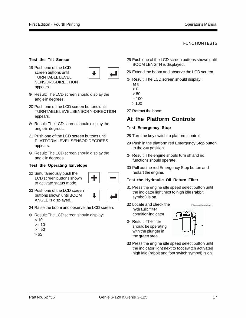
Test the Hydraulic Oil Return Filter
31 Press the engine idle speed select button untilthe indicator light next to high idle (rabbitsymbol) is on.
32 Locate and check thehydraulic filtercondition indicator.
Result: The filtershould be operatingwith the plunger inthe green area.
33 Press the engine idle speed select button untilthe indicator light next to foot switch activatedhigh idle (rabbit and foot switch symbol) is on.

18 Genie S-120 & Genie S-125 Part No. 62756
Operator's Manual First Edition · Fourth Printing
FUNCTION TESTS
Test the Horn
34 Push the horn button.
Result: The horn should sound.
Test the Tilt Sensor Alarm
35 Push a button, such as the engine RPM buttonor the fuel select button.
Result: The alarm should sound at the platformcontrols.
Test the Foot Switch
36 Push in the platform red Emergency Stop buttonto the OFF position.
37 Pull out the red Emergency Stop button tothe ON position but do not start the engine.
38 Press down the foot switch and attempt to startthe engine by pushing the engine start button.
Result: The engine should not start.
39 Do not press down the foot switch and restartthe engine.
40 Do not press down the foot switch and test eachmachine function.
Result: No machine functions should operate.
Test Machine Functions
41 Press down the foot switch.
42 Activate each machine function control handle,toggle switch or button.
Result: All functions should operate through afull cycle.
Test the Steering
43 Push the steermode selectbutton for square-end (blue arrow)steer.
44 Press down the foot switch.
45 Slowly move the drive/steer control handle in thedirection indicated by the blue triangle on thecontrol panel OR press the thumb rocker switch inthe direction indicated by the blue triangle.
Result: The square-end wheels should turn inthe direction that the blue triangles point on thedrive chassis.
46 Push the steermode selectbutton for circle-end (yellow arrow)steer.
47 Press down the foot switch.
48 Slowly move the drive/steer control handle in thedirection indicated by the yellow triangle on thecontrol panel OR press the thumb rocker switch inthe direction indicated by the yellow triangle.
Result: The circle-end wheels should turn in thedirection that the yellow triangles point on thedrive chassis.
49 Push the steermode selectbutton for crabsteer.
50 Press down the foot switch.
51 Slowly move the drive/steer control handle in thedirection indicated by the blue triangle on thecontrol panel OR press the thumb rocker switch inthe direction indicated by the blue traingle..
Result: All wheels should turn in the directionthat the blue triangles point on the drivechassis.
Part No. 62756 Genie S-120 & Genie S-125 19
Operator's ManualFirst Edition · Fourth Printing
52 Push the steermode selectbutton forcoordinated steer.
53 Press down the foot switch.
54 Slowly move the drive/steer control handle in thedirection indicated by the blue triangle on thecontrol panel OR press the thumb rocker switch inthe direction indicated by the blue traingle..
Result: The square-end wheels should turn inthe direction that the blue triangles point on thedrive chassis. The circle-end wheels should turnin the direction that the yellow triangles point onthe drive chassis.
Test Drive and Braking
55 Press down the foot switch.
56 Slowly move the drive/steer control handle in thedirection indicated by the blue arrow on thecontrol panel until the machine begins to move,then return the handle to the center position.
Result: The machine should move in thedirection that the blue arrow points on the drivechassis, then come to an abrupt stop.
57 Slowly move the drive/steer control handle in thedirection indicated by the yellow arrow on thecontrol panel until the machine begins to move,then return the handle to the center position.
Result: The machine should move in thedirection that the yellow arrow points on thedrive chassis, then come to an abrupt stop.
Note: The brakes must be able to hold the machineon any slope it is able to climb.
Blue
Yellow
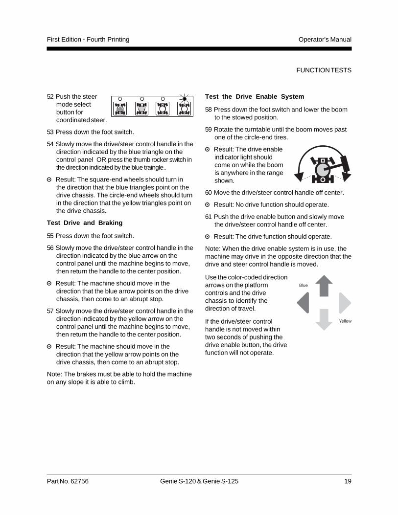
Test the Drive Enable System
58 Press down the foot switch and lower the boomto the stowed position.
59 Rotate the turntable until the boom moves pastone of the circle-end tires.
Result: The drive enableindicator light shouldcome on while the boomis anywhere in the rangeshown.
60 Move the drive/steer control handle off center.
Result: No drive function should operate.
61 Push the drive enable button and slowly movethe drive/steer control handle off center.
Result: The drive function should operate.
Note: When the drive enable system is in use, themachine may drive in the opposite direction that thedrive and steer control handle is moved.
Use the color-coded directionarrows on the platformcontrols and the drivechassis to identify thedirection of travel.
If the drive/steer controlhandle is not moved withintwo seconds of pushing thedrive enable button, the drivefunction will not operate.
FUNCTION TESTS

20 Genie S-120 & Genie S-125 Part No. 62756
Operator's Manual First Edition · Fourth Printing
FUNCTION TESTS
Test Limited Drive Speed
62 Press down the foot switch.
63 Raise the boom to 10° above horizontal.
64 Slowly move the drive control handle to the fulldrive position.
Result: The maximum achievable drive speedwith the boom raised should not exceed 1 footper second (0.3 meters per second).
Note: The machine will travel 40 feet in 40 seconds(12.2 meters in 40 seconds).
65 Lower the boom to the stowed position.
66 Extend the boom 4 feet (1.2 m).
67 Slowly move the drive control handle to the fulldrive position.
Result: The maximum achievable drive speedwith the boom extended should not exceed 1foot per second (0.3 meters per second).
Note: The machine will travel 40 feet in 40 seconds(12.2 meters in 40 seconds).
If the drive speed with the boom raised orextended exceeds 1 foot per second (0.3 metersper second), immediately tag and remove themachine from service.
68 Raise the boom to horizontal. Extend the boomas far as it will go.
69 Slowly move the drive control handle to the fulldrive position.
Result: The maximum achievable drive speedwith the boom fully extended should not exceed0.6 feet per second (0.2 meters per second).
Note: The machine will travel 40 feet in 70 seconds(12.2 meters in 70 seconds).
Test Auxiliary Controls
70 Shut off the engine.
71 Pull out the red Emergency Stop button tothe ON position.
72 Press down the foot switch.
73 Simultaneously press and hold the auxiliarypower button and activate each function controlhandle, toggle switch or button.
Note: To conserve battery power, test eachfunction through a partial cycle.
Result: All boom and steer functions shouldoperate.Machines equipped with the auxiliary powerdrive option: The drive function should operate.

Part No. 62756 Genie S-120 & Genie S-125 21
Operator's ManualFirst Edition · Fourth Printing
Work Place Inspection
Work Place Inspection
Be aware of and avoid the following hazardoussituations:
· drop-offs or holes
· bumps, floor obstructions or debris
· overhead obstructions and high voltageconductors
· hazardous locations
· inadequate surface support to withstand all loadforces imposed by the machine
· wind and weather conditions
· the presence of unauthorized personnel
· other possible unsafe conditions
Do Not Operate Unless:
You learn and practice the principles of safemachine operation contained in this operator'smanual.
1 Avoid hazardous situations.
2 Always perform a pre-operationinspection.
3 Always perform function tests prior to use.
4 Inspect the work place.
Know and understand the above principlesbefore going on to the next section.
5 Only use the machine as it was intended.
Fundamentals
The Work Place Inspection helps the operatordetermine if the work place is suitable for safemachine operation. It should be performed by theoperator prior to moving the machine to the workplace.
It is the operator's responsibility to read andremember the work place hazards, then watch forand avoid them while moving, setting up andoperating the machine.
22 Genie S-120 & Genie S-125 Part No. 62756
Operator's Manual First Edition · Fourth Printing
Operating Instructions
Starting the Engine
1 At the ground controls, turn the key switch tothe desired position.
2 Be sure both the ground and platform controlred Emergency Stop buttons are pulled out tothe ON position.
3 Gasoline/LPG models: Choose fuel by pressingthe fuel select button.
4 Press the engine start button. Ifthe engine fails to start or dies, therestart delay will disable the startbutton for 3 seconds.
If the engine fails to start after 15 seconds ofcranking, determine the cause and repair anymalfunction. Wait 60 seconds before trying to startagain.
All models: In extreme cold conditions, 20°F (-6°C)and below, warm the engine for 5 minutes toprevent hydraulic system damage.
Gasoline/LPG models: In extreme cold conditions,20°F (-6°C) and below, the machine should bestarted on gasoline, then switched to LPG.
Emergency Stop
Push in either the ground or platform redEmergency Stop button to the OFF position to stopall functions and turn the engine off.
Repair any function that operates when theEmergency Stop button is pushed in to the OFF
position.
Selecting and operating the ground controls willoverride the platform Emergency Stop button.
Do Not Operate Unless:
You learn and practice the principles of safemachine operation contained in this operator'smanual.
1 Avoid hazardous situations.
2 Always perform a pre-operationinspection.
3 Always perform function tests prior to use.
4 Inspect the work place.
5 Only use the machine as it was intended.
Fundamentals
The Operating Instructions section providesinstructions for each aspect of machine operation.It is the operator's responsibility to follow all thesafety rules and instructions in the operator's,safety and responsibilities manuals.
Using the machine for anything other than liftingpersonnel and tools to an aerial work site is unsafeand dangerous.
Only trained and authorized personnel should bepermitted to operate a machine. If more than oneoperator is expected to use a machine at differenttimes in the same work shift, they must all bequalified operators and are all expected to follow allsafety rules and instructions in the operator's,safety and responsibilities manuals. That meansevery new operator should perform a pre-operationinspection, function tests, and a work placeinspection before using the machine.

Part No. 62756 Genie S-120 & Genie S-125 23
Operator's ManualFirst Edition · Fourth Printing
OPERATING INSTRUCTIONS
Operation from Platform
1 Turn the key switch to platform control.
2 Pull out both ground and platform redEmergency Stop buttons to the ON position.
3 Gasoline/LPG models: Choose fuel by pressingthe fuel select button.
4 Start the engine. Do not press down the footswitch when starting the engine.
To Position Platform
1 Press down the foot switch.
2 Slowly move the appropriate function controlhandle or toggle switch or press the appropriatebutton according to the markings on the controlpanel.
To Steer
1 Press down the foot switch.
2 Select the steer mode by pressing a steer modebutton. The indicator light next to the currentsteer mode will be on.
3 Slowly move the drive/steercontrol handle in the blue oryellow triangle directionOR press the thumb rober switch located on topof the drive control handle.
Use the color-coded direction arrows on theplatform controls and the drive chassis to identifythe direction the wheels will turn.
Auxiliary Controls
Use auxiliary power if the primary power source(engine) fails.
1 Turn the key switch to ground or platformcontrol.
2 Pull out the red Emergency Stop button to theON position.
3 Press down the foot switch when operating theauxiliary controls from the platform.
4 Simultaneously hold the auxiliary power buttonand activate the desired function.
Machines equipped with the auxiliary power driveoption: The drive function will operate.
Operation from Ground
1 Turn the key switch to ground control.
2 Pull out the red Emergency Stop button tothe ON position.
3 Gasoline/LPG models: Choose fuel by pressingthe fuel select button.
4 Start the engine.
To Position Platform
1 Push and hold a function enable/speed select button.
2 Push the appropriate function buttonaccording to the markings on thecontrol panel.
Drive and steer functions are notavailable from the ground controls.
24 Genie S-120 & Genie S-125 Part No. 62756
Operator's Manual First Edition · Fourth Printing
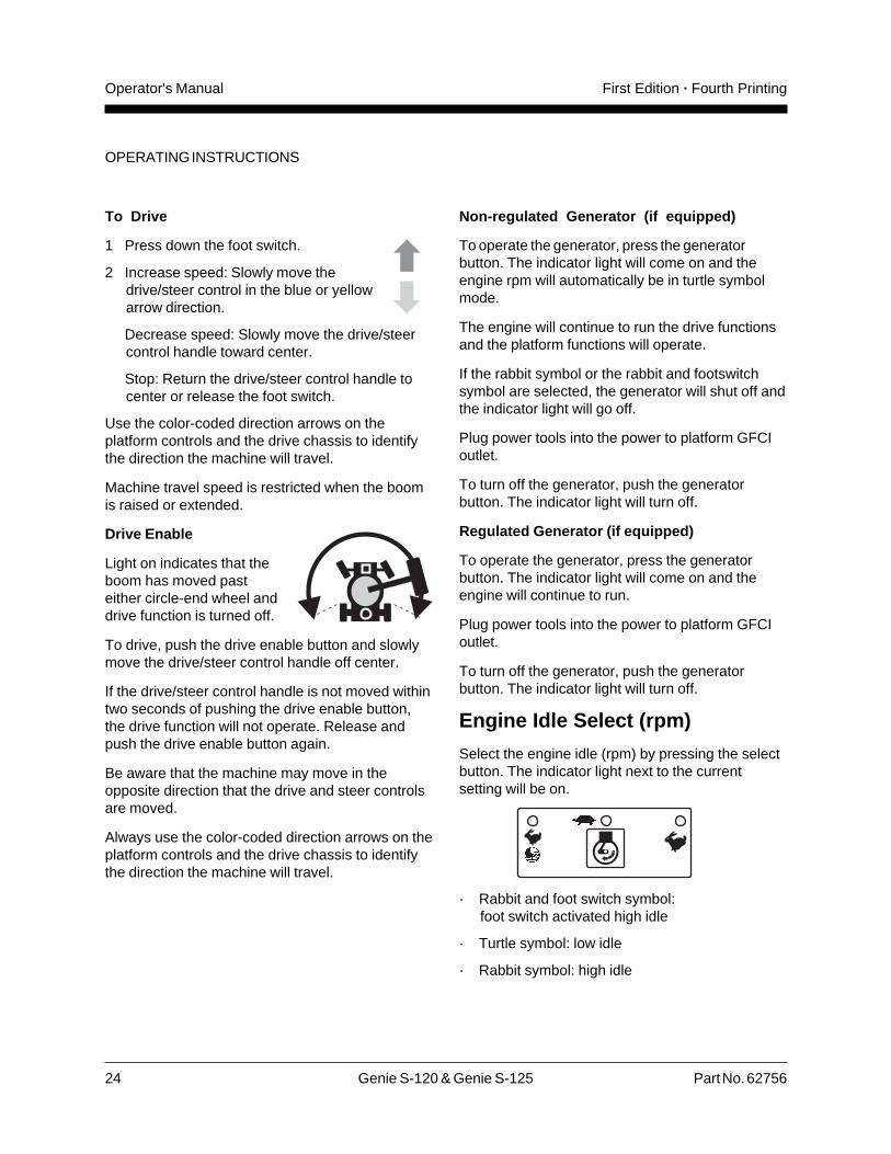
To Drive
1 Press down the foot switch.
2 Increase speed: Slowly move thedrive/steer control in the blue or yellowarrow direction.
Decrease speed: Slowly move the drive/steercontrol handle toward center.
Stop: Return the drive/steer control handle tocenter or release the foot switch.
Use the color-coded direction arrows on theplatform controls and the drive chassis to identifythe direction the machine will travel.
Machine travel speed is restricted when the boomis raised or extended.
Drive Enable
Light on indicates that theboom has moved pasteither circle-end wheel anddrive function is turned off.
To drive, push the drive enable button and slowlymove the drive/steer control handle off center.
If the drive/steer control handle is not moved withintwo seconds of pushing the drive enable button,the drive function will not operate. Release andpush the drive enable button again.
Be aware that the machine may move in theopposite direction that the drive and steer controlsare moved.
Always use the color-coded direction arrows on theplatform controls and the drive chassis to identifythe direction the machine will travel.
OPERATING INSTRUCTIONS
Non-regulated Generator (if equipped)
To operate the generator, press the generatorbutton. The indicator light will come on and theengine rpm will automatically be in turtle symbolmode.
The engine will continue to run the drive functionsand the platform functions will operate.
If the rabbit symbol or the rabbit and footswitchsymbol are selected, the generator will shut off andthe indicator light will go off.
Plug power tools into the power to platform GFCIoutlet.
To turn off the generator, push the generatorbutton. The indicator light will turn off.
Regulated Generator (if equipped)
To operate the generator, press the generatorbutton. The indicator light will come on and theengine will continue to run.
Plug power tools into the power to platform GFCIoutlet.
To turn off the generator, push the generatorbutton. The indicator light will turn off.
Engine Idle Select (rpm)
Select the engine idle (rpm) by pressing the selectbutton. The indicator light next to the currentsetting will be on.
· Rabbit and foot switch symbol:foot switch activated high idle
· Turtle symbol: low idle
· Rabbit symbol: high idle

Part No. 62756 Genie S-120 & Genie S-125 25
Operator's ManualFirst Edition · Fourth Printing
OPERATING INSTRUCTIONS
Check Engine Light
Light on and engine stopped: Tag the machine andremove from service.
Light on and engine still running: Contact servicepersonnel within 24 hours.
Operating Envelope IndicatorLights
The operating envelope indicator lights will comeon to notify the operator that a function has beeninterrupted (in some cases) and/or an action isrequired by the operator.
Raise Boom indicator lightflashing: To continue extendingthe boom, raise the boom until theindicator light is off.
Retract Boom indicator lightflashing: To continue lowering theboom, retract the boom until theindicator light is off.
Machine Not Level indicator lightflashing: The tilt alarm will besounding when this light isflashing. Move the machine to afirm level surface.
Platform Not Level indicator lightflashing:The tilt alarm will besounding when this light isflashing. The Platform Level toggle switch will onlywork in the direction that will level the platform.Level the platform until the indicator light is off.
Stopping the Engine
Push in the red Emergency Stop button and turnthe key switch to the OFF position.
After Each Use
1 Select a safe parking location—firm levelsurface, clear of obstruction and traffic.
2 Retract and lower the boom to the stowedposition.
3 Rotate the turntable so that the boom isbetween the circle-end wheels.
4 Turn the key switch to the OFF position andremove the key to secure from unauthorizeduse.
5 Chock the wheels.
26 Genie S-120 & Genie S-125 Part No. 62756
Operator's Manual First Edition · Fourth Printing
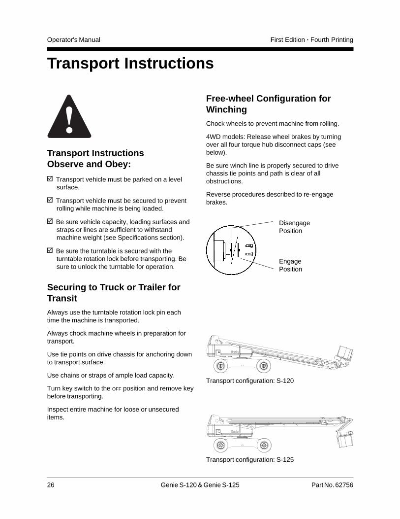
Free-wheel Configuration forWinchingChock wheels to prevent machine from rolling.
4WD models: Release wheel brakes by turningover all four torque hub disconnect caps (seebelow).
Be sure winch line is properly secured to drivechassis tie points and path is clear of allobstructions.
Reverse procedures described to re-engagebrakes.
Transport InstructionsObserve and Obey:
Transport vehicle must be parked on a levelsurface.
Transport vehicle must be secured to preventrolling while machine is being loaded.
Be sure vehicle capacity, loading surfaces andstraps or lines are sufficient to withstandmachine weight (see Specifications section).
Be sure the turntable is secured with theturntable rotation lock before transporting. Besure to unlock the turntable for operation.
Securing to Truck or Trailer forTransitAlways use the turntable rotation lock pin eachtime the machine is transported.
Always chock machine wheels in preparation fortransport.
Use tie points on drive chassis for anchoring downto transport surface.
Use chains or straps of ample load capacity.
Turn key switch to the OFF position and remove keybefore transporting.
Inspect entire machine for loose or unsecureditems.
Transport Instructions
Transport configuration: S-120
Transport configuration: S-125
DisengagePosition
EngagePosition

Part No. 62756 Genie S-120 & Genie S-125 27
Operator's ManualFirst Edition · Fourth Printing
Shading indicates decal is hidden from view, i.e.under covers
Decals
Part No. Description Quantity
25994 Caution, Component Damage Hazard 1
27204 Arrow, Blue 1
27205 Arrow, Yellow 1
27206 Triangle, Blue 2
27207 Triangle, Yellow 2
27564 Danger - Electrocution Hazard 4
28157 Label - Dexron 1
28159 Label, Diesel 1
28161 Warning, Crush Hand 4
28163 Notice, Max. Side Force, 150 lbs,ANSI & CSA 1
28164 Notice, Hazardous Materials 1
28165 Notice, Footswitch 1
28171 Label, No Smoking 1
28174 Label, Power to Platform, 230V 2
28175 Caution, Compartment Access 1
28176 Notice, Missing Manuals 1
28177 Warning, Collision Hazard 2
28181 Warning, No Step or Ride 1
28235 Label, Power to Platform, 115V 2
28236 Warning, Failure To Read . . . 1
30080 Notice, Maximum Capacity, 500 lbs, S-125 1
32700 Danger, General Safety 2
33952 Danger, Tip-over Hazard 1
40434 Label, Lanyard Anchorage Point 2
43594 Notice, Maximum Capacity, 750 lbs, S-120 1
44986 Notice, Max. Manual Force, 90 lbs, CE 1
61227 Ground Control Panel 1
Decal InspectionUse the pictures on the next page to verify that alldecals are legible and in place.
Below is a numerical list with quantities anddescriptions.
Part No. Description Quantity
65182 Platform Control Panel 1
65264 Cosmetic, Genie S-125 1
65265 Cosmetic, S-125 1
65266 Cosmetic, 4x4 1
65267 Cosmetic, Genie S-120 1
65268 Cosmetic, S-120 1
65269 Notice, Operating Instructions 2
65272 Serial Plate 1
65273 Notice, Tire Specifications 4
65274 Notice, Engine Specifications, Deutz 1
65275 Notice, Engine Specifications, Cummins 1
65276 Notice, Engine Specifications, Perkins 1
65278 Caution, No Step 4
65428 Danger, Tip-over Hazard, Tires 4
72051 Label, 20 amp Circuit Breaker 1
72052 Label, 40 amp Circuit Breaker 1
72053 Label, 30 amp Circuit Breaker 1
72087 Warning, Weld Line to Platform 2
72119 Label, Range of Motion Chart 1
72130 Warning, Bodily Injury Hazard 2
72131 Label, Cylinder Cover 2
72168 Notice, Starter Battery 1
72169 Notice, Controls Battery 1
72866 Warning, Explosion Hazard 2

28 Genie S-120 & Genie S-125 Part No. 62756
Operator's Manual First Edition · Fourth Printing
DECALS

Part No. 62756 Genie S-120 & Genie S-125 29
Operator's ManualFirst Edition · Fourth Printing
Specifications
S-120
Height, working maximum 126 ft 38.4 m
Height, platform maximum 120 ft 36.6 m
Height, stowed maximum 10 ft 1 in 3.1 m
Horizontal reach maximum 75 ft 22.9 m
Width, axles retracted 8 ft 6 in 2.6 m
Width, axles extended 11 ft 6 in 3.5 m
Length, stowed 39 ft 11 in 12.2 m
Maximum load capacity 750 lb 340 kg
Wheelbase 12 ft 3.7 m
Turning radius, outside, 24 ft 4 in 7.4 maxles retracted
Turning radius, inside, 16 ft 4 in 4.9 maxles retracted
Turning radius, outside, 20 ft 8 in 6.3 maxles extended
Turning radius, inside, 10 ft 1 in 3.1 maxles extended
Turntable rotation (degrees) 360 continuous
Turntable tailswing, 66 in 168 cmaxles retracted
Turntable tailswing 48 in 122 cmaxles extended
Power source Perkins Diesel 1004-42(choice) Deutz Diesel F4L913
Cummins Diesel 4B3.9
Drive speed, stowed 3.0 mph 4.4 km/h40 ft/9.1 sec 12.2 m/9.1 sec
Drive speed, 0.7 mph 1.1 km/hraised or extended 40 ft/40 sec 12.2 m/40 sec
Drive speed, 0.4 mph 0.6 km/hfully extended 40 ft/70 sec 12.2 m/70 sec
S-120
Controls 12V DC proportional
Platform dimensions, 96 x 36 inlength x width 2.4 m x 91 cm
Platform leveling self-leveling
Platform rotation 160°
AC outlet in platform standard
Hydraulic pressure (maximum) 4250 psi 293 bar(drive functions)
Tire size 18 x 22.5, 18 pr FF
Gradeability, stowed 40 %
Ground clearance 153/4 in 40 cm
Hydraulic tank capacity 55 gallons 208 liters
Fuel tank capacity 40 gallons 151 liters
Weight 44,340 lbs 20,112 kg
Airborne noise emissions 80 dBMaximum sound level at normal operating workstations(A-weighted)
Continuous improvement of our products is a Geniepolicy. Product specifications are subject to changewithout notice or obligation.
30 Genie S-120 & Genie S-125 Part No. 62756
Operator's Manual First Edition · Fourth Printing
SPECIFICATIONS
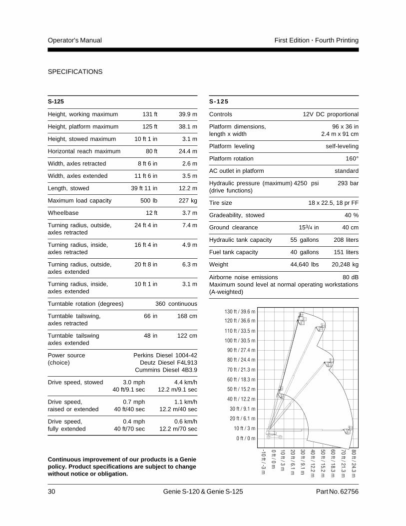
S-125
Height, working maximum 131 ft 39.9 m
Height, platform maximum 125 ft 38.1 m
Height, stowed maximum 10 ft 1 in 3.1 m
Horizontal reach maximum 80 ft 24.4 m
Width, axles retracted 8 ft 6 in 2.6 m
Width, axles extended 11 ft 6 in 3.5 m
Length, stowed 39 ft 11 in 12.2 m
Maximum load capacity 500 lb 227 kg
Wheelbase 12 ft 3.7 m
Turning radius, outside, 24 ft 4 in 7.4 maxles retracted
Turning radius, inside, 16 ft 4 in 4.9 maxles retracted
Turning radius, outside, 20 ft 8 in 6.3 maxles extended
Turning radius, inside, 10 ft 1 in 3.1 maxles extended
Turntable rotation (degrees) 360 continuous
Turntable tailswing, 66 in 168 cmaxles retracted
Turntable tailswing 48 in 122 cmaxles extended
Power source Perkins Diesel 1004-42(choice) Deutz Diesel F4L913
Cummins Diesel 4B3.9
Drive speed, stowed 3.0 mph 4.4 km/h40 ft/9.1 sec 12.2 m/9.1 sec
Drive speed, 0.7 mph 1.1 km/hraised or extended 40 ft/40 sec 12.2 m/40 sec
Drive speed, 0.4 mph 0.6 km/hfully extended 40 ft/70 sec 12.2 m/70 sec
S-125
Controls 12V DC proportional
Platform dimensions, 96 x 36 inlength x width 2.4 m x 91 cm
Platform leveling self-leveling
Platform rotation 160°
AC outlet in platform standard
Hydraulic pressure (maximum) 4250 psi 293 bar(drive functions)
Tire size 18 x 22.5, 18 pr FF
Gradeability, stowed 40 %
Ground clearance 153/4 in 40 cm
Hydraulic tank capacity 55 gallons 208 liters
Fuel tank capacity 40 gallons 151 liters
Weight 44,640 lbs 20,248 kg
Airborne noise emissions 80 dBMaximum sound level at normal operating workstations(A-weighted)
Continuous improvement of our products is a Geniepolicy. Product specifications are subject to changewithout notice or obligation.

Genie North America
Genie Australia Pty Ltd.
Genie China
Genie Malaysia
Genie Japan
Genie Korea
Genie Africa
Genie Latin America
Phone
Toll Free
Fax
Phone +
Fax +
Phone +
Fax +
Phone +
Fax +
Phone +
Fax +
Phone +
Fax +
Phone +
Fax +
Phone +
Fax +
425.881.1800
USA and Canada
800.536.1800
425.883.3475
61 7 3375 1660
61 7 3375 1002
86 21 53852570
86 21 53852569
60 4 228 1235
60 4 226 6872
81 3 3453 6082
81 3 3453 6083
82 2 558 7267
82 2 558 3910
27 11 455 0373
27 11 455 0355
55 11 4055 2499
55 11 4043 1661
Genie Holland
Genie Scandinavia
Genie France
Genie Iberica
Genie Germany
Genie U.K.
Genie Mexico City
Phone +
Fax +
Phone +
Fax +
Phone +
Fax +
Phone +
Fax +
Phone +
Fax +
Phone +
Fax +
Phone +
Fax +
31 70 51 78836
31 70 51 13993
46 31 3409612
33 (0)2 37 26 09 99
33 (0)2 37 26 09 98
34 93 579 5042
34 93 579 5059
49 (0)4202 88520
49 (0)4202 8852-20
44 (0)1476 584333
44 (0)1476 584334
52 5 653 03 84
52 5 664 40 16
46 31 3409613
Dis
trib
ute
dB
y:
California Proposition 65
WARNINGThe exhaust from this product contains chemicals
known to the State of California to cause cancer,
birth defects or other reproductive harm.


![4N[sic] - Electrocution](https://img.pdfslide.us/doc/110x75/5875aa491a28ab8b618b47a9/4nsic-electrocution.jpg)