Embed Size (px)
Citation preview

Operator’s Manual for the Coating Thickness Measuring Instrument
DUALSCOPE® MP0R USB DUALSCOPE® MP0RH USB DUALSCOPE® MP0R-FP USB DUALSCOPE® MP0RH-FP USB ISOSCOPE® MP0R USB and variants
DKD-K-33101

2
Operator’s Manual for ISOSCOPE® MP0R USB; DUALSCOPE®
MP0R(-FP) USB DUALSCOPE® MP0RH(-FP) USB Documentation order #: 952-584 Version 4.2 11/2006 Applies to software versions P0R04 and higher Manufacturer: HELMUT FISCHER GMBH+CO.KG Institute for Electronics and Measuring Technology Industriestrasse 21 71069 Sindelfingen, Germany Phone ++49 (0) 70 31 30 30 Fax ++49 (0) 70 31 30 379 Internet www.Helmut-Fischer.com eMail [email protected]
© 2006 by Helmut Fischer GmbH+Co.KG, Sindelfingen/Germany. This operator’s manual remains the copyrighted property of Helmut Fischer GmbH+Co.KG. All rights reserved. This manual may not be reproduced by any means (print, photocopy, microfilm or any other method) in full or in part, or processed, multiplied or distributed to third parties by electronic means without the written consent of Helmut Fischer GmbH+Co.KG. Subject to technical changes and corrections. ISOSCOPE® and DUALSCOPE® are registered trademarks of Helmut Fischer GmbH+Co.KG, Sindelfingen, Germany.

3
Table of Contents Page 1 Switching the instrument ON / OFF (valid for all instrument models except the “…-FP” models)......................... 5 2 Switching the “…-FP” instrument models ON / OFF............................................................................................. 6 3 Main Menu – Functional Overview ....................................................................................................................... 7 4 Measurements on coating material....................................................................................................................... 8 5 Evaluation of a test series (Statistics function) ................................................................................................... 10 6 Transmitting data to a computer ......................................................................................................................... 12
6.1 Transmitting only the current reading ......................................................................................................... 12 6.2 Transmitting all measurement data in the instrument memory ................................................................... 13 6.3 Sending the current mean value ................................................................................................................. 13
6.3.1 Triggering the mean value transmission manually .............................................................................. 14 6.3.2 Sending the mean value automatically................................................................................................ 14
7 Deleting measurements...................................................................................................................................... 15 7.1 Deleting only the last reading...................................................................................................................... 15

4
7.2 Deleting all measurement data from the measurement data memory ........................................................ 15 8 Normalizing......................................................................................................................................................... 16 9 Calibration .......................................................................................................................................................... 18 10 Deleting a calibration / Restoring the baseline of the characteristic................................................................. 20 11 Setting the specification limits........................................................................................................................... 22 12 Deleting the specification limits......................................................................................................................... 24 13 Triggering the group separator ......................................................................................................................... 25 14 Service Menus.................................................................................................................................................. 27 15 Trouble Shooting .............................................................................................................................................. 34 16 Technical data .................................................................................................................................................. 39 17 Order information for instruments and accessories .......................................................................................... 46

5
1 Switching the instrument ON / OFF (valid for all instrument models except the “…-FP” models) Note: The instrument does not have a specific ON / OFF switch.
Switching the instrument ON The instrument will switch ON automatically when it is placed on a specimen. If the instrument is placed on nonferromagnetic or electrically nonconductive material, the display will show the error note "Er6" and then four horizontal bars instead of a reading.
PLEASE NOTE! Do not power up the instrument by pressing a finger on the sensor! It may result in erroneous measurements. Switching the instrument OFF / Auto-Switch-Off After a certain time, the instrument will switch off automatically (OFF = when instrument’s display is empty) You can set the period from the last measurement to the automatic OFF from the service mode. See chapter 14 “Service Menus”, page 27.

6
2 Switching the “…-FP” instrument models ON / OFF Note: The on/off operation is different to the other MP0R models!. Switching the “…-FP” instrument ON The ON key is the key [OK]. Switch the instrument ON by pressing the key [OK]
Switching the instrument OFF / Auto-Switch-Off After a certain time, the instrument will switch off automatically (OFF = when instrument’s display is empty) You can set the period from the last measurement to the automatic OFF from the service mode. See chapter 14 “Service Menus”, page 27.

7
3 Main Menu – Functional Overview Select the specific sub-menus with [ ] or [ ] and press key [OK].

8
4 Measurements on coating material
Making measurements with the MP0R: 1. With the instrument switched ON, place the instrument on the specimen and wait, until the acoustic signal
sounds. The instrument will switch ON automatically this way. 2. Lift the instrument off the specimen.
The acoustic signal sounds and the reading will be displayed. Note: when lifting the instrument too early (before the beep sound), the error note "Er6" will appear. In this case, repeat step #1. The measurement is transmitted automatically to the radio receiver (cf. chapter 14 “Service Menus”, page 27, menu 3, “radio transmission ON/OFF”. The transmission is indicated by the flashing radio tower symbol.
3. When measuring with an instrument which is already swiched ON, a reading will be displayed at once. As well as with an instrument placed on the specimen and with the instrument lifted off.

9
Measurement with the MP0R instrument

10
5 Evaluation of a test series (Statistics function) Prerequisite: At least two readings must be saved in the measurement data memory. Note: The measurement data memory must always be empty before starting a test series that is to be evaluated (cf. chapter 7 "Deleting measurements", page 15). If at least two readings are not stored in memory when you first press RES and then [OK], the statistical evaluation will NOT start. Statistical evaluation of a test series: 1. The display menu shows "RES". This is the default setting of the instrument. If RES is not currently shown on
the display, use the arrow key [ ] or [ ] to switch to this setting. 2. Press button [OK] repeatedly.
After each [OK], the display will change to the next statistic number (see table below). 3. Press [ESC] or do further measurements to continue a block. This allows to do statistical evaluations within a
test series.

11
Display Explanation
Mean value (= arithmetic mean value)
s Standard deviation (= mean square deviation of the single readings from the mean value)
N Number of measurements in the test series MIN Lowest value in the test series MAX Highest value in the test series
Meaning of statistical evaluation data shown in the display.
12
6 Transmitting data to a computer The RS232 radio interface integrated in the instrument facilitates the transmission of the data stored in the measurement data memory to an optional radio receiver (order no. of US-receiver version: 603-544). The radio receiver, in turn, transmits the data to the evaluation computer via a cable. There is a separate operator's manual for the optional radio receiver. Prerequisite for all following sub-chapters: Settings of service menu must be “rF = 1” e.g. the radio transmitter is active. See chapter 14 “Service menu”, menu #3”, radio transmission, page 26.
6.1 Transmitting only the current reading Independent of the current menu selection, each reading is radioed to the computer automatically. At the same time, the reading is accepted into the measurement data memory of the instrument and can be evaluated statistically.

13
6.2 Transmitting all measurement data in the instrument memory
1. Set the display menu with [ ] or [ ] to show . 2. Press button [OK].
All readings in the memory are then radioed to the PC. This is indicated by the flashing radio tower symbol.
6.3 Sending the current mean value Prerequisite for following sub-chapters of 5.3: Settings of service menu must be “SI = 0” e.g. mean value transmission is active. See chapter 14 “Service menu, menu #4”, menu mean value transmission”.

14
6.3.1 Triggering the mean value transmission manually Prerequisite: Settings of service menu must be “bL = 1” e.g. mean value transmission is active. See chapter 14 “Service menu, menu #1”, menu point “Block length”. 1. Make desired number of measurements. 2. Set the display menu with [ ] or [ ] to show "RES”. Press button [OK]. The mean value of the readings in the
memory are then radioed to the PC. This is indicated by the flashing radio tower symbol.
6.3.2 Sending the mean value automatically Prerequisite: Service menu settings of “bL” must be between 2 and 20. The set value indicates the number of readings, which are collected in one block. See chapter 14 “Service menu”. 1. Make desired number of measurements. 2. Indepentently of the pre-set number of readings/block, a block mean value is radioed and a new block will be
begun.

15
7 Deleting measurements 7.1 Deleting only the last reading 1. Select the menu DEL with [ ] or [ ]. 2. Press button [OK]. The last reading will be deleted.
7.2 Deleting all measurement data from the measurement data memory 1. Select the menu RES with [ ] or [ ]. 2. Press button [OK]. 3. Select the menu DEL with [ ] or [ ]. 4. Press button [OK]. All measurement data will be deleted from the measurement data memory.

16
8 Normalizing A normalization is used to adjust the measuring instrument to a measuring task. The symbol on the display of the instrument indicates the “Normalization” operating mode. The following items are required for performing a normalization: • Uncoated specimen.
In geometry and substrate material, this specimen should correspond exactly to the parts to be measured. Note: All readings in the memory will be deleted when performing a normalization. Normalizing the instrument: Prerequisite: Instrument must be turned ON. 1. Select the menu (normalization) with button [ ] or [ ]. 2. Press button [OK]. The message "Base" (for “substrate (base) material”) appears.

17
3. Perform about 5 measurements on the uncoated specimen. After each measurement, the current reading will appear on the display. Note: If you want to delete wrong readings, press button [ESC]. Then, the complete data memory will be deleted, but the normalization routine will not be interrupted. After that, perform five more measurements.
4. Press button [OK]. By pressing button [OK], the mean value of all readings will be calculated and used for normalization. Thus, a good normalization is possible on rough surfaces as well. The mean value is set to zero. The reading 0.00 will appear on the display. Finished.
Note: the function „Normalization“ can be locked to protect the instrument from unintended interventions. Cf. Chapter 14 „Service menu“. If the normalization is called while the function lock (display: ) is active, the error note „Er29“ will appear on the display.

18
9 Calibration The following items are required for performing a calibration: An uncoated specimen: In geometry & substrate material, this specimen should correspond exactly to the parts to be measured and a calibration standard (instrument-specific correction foil 75 µm (3 mils)). Note: All readings in the memory will be deleted when performing a calibration. Calibrating the instrument (Prerequisite: Instrument must be turned ON) 1. Select the menu with button [ ] or [ ]. 2. Press button [OK]. The message "Base" (for “substrate (base) material”) appears. 3. Perform about 5 measurements on the uncoated specimen. After each measurement, the current reading will
appear on the display. (continued on next page!) 4. Press button [OK].
By pressing button [OK], the mean value of all readings will be calculated and used for normalization.

19
The mean value is set to zero. The reading 0.00 will appear on the display. The message STD1 (that is, calibration standard # 1) appears.
5. Place the calibration foil on the uncoated specimen and perform about 5 measurements. After each measurement, the current single reading will appear on the display. Note: If you want to delete wrong readings, press button [ESC]. Then, the complete data memory will be deleted, but the calibration routine will not be interrupted. In this case, repeat the test series with the calibration foil.
6. On the display, set the NOMINAL value for the calibration standard, e.g., "75 µm". Use the arrow key [ ] or [ ]. The NOMINAL value of the calibration standard is printed on the standard.
7. Press button [OK]. By pressing [OK], the mean value of all readings from step 5 will be used for calibration. Note: the function „Calibration“ can be locked to protect the instrument from unintended interventions. Cf. Chapter 14 „Service menu“. If the calibration is called while the function lock (display: ) is active, the error note „Er29“ will appear on the display.

20
10 Deleting a calibration / Restoring the baseline of the characteristic Sometimes, if an instrument does not measure correctly even after a calibration, the calibration can be deleted. This can occur if the previous calibration has not been carried out correctly. In such a case, the baseline of the characteristic can be restored to its original factory condition. Note to users of the DUALSCOPE MP0R (instrument version with two measurement channels): the base line of each of the two measurement channels must be restored separately (Fe Base and Al Base required).
Deleting the calibration of the instrument: (Instructions continued on next page) Prerequisite: Instrument is switched ON.
1. Select the menu option (i.e., calibration) using button [ ] or [ ]. 2. Press button [OK]. "Base" (i.e., “substrate material”) will appear on the display.
The instrument is now in calibration mode.

21
3. Perform three to five measurements on the uncoated specimen. The current reading appears on the display after each measurement.
4. Press button [OK]. Note: When pressing [OK], the mean value of all measurements is used as the normalization value. This mean value is set to 0. The display shows 0.00. STD1 (that is, calibration standard # 1) appears on the display.
5. Measure at least two times on the uncoated specimen. A reading will appear. 6. Use button [ ] or [ ] to set the displayed value to 0.00. 7. Press button [OK]. The baseline of the characteristic is restored.
Ready. The instrument is again ready to measure, but you must do a corrective calibration prior to measuring. Cf. Chapter 9 Calibration.

22
11 Setting the specification limits Example: Lower specification limit (MIN): 20 µm; upper specification limit (MAX): 40 µm
Setting the specification limits: 1. On the display, set the specification limit mode using the arrow key [ ] or [ ]. 2. Press button [OK]. " - - - " and MIN appear on the display. This means that no values are stored in memory
and that the instrument is ready for entering the MIN value; i.e., it is ready to enter the lower specification limit. 3. Make one measurement on the specimen that is to be tested. 4. Set the desired MIN value using the key [ ] or [ ]. Example: the lower specification limit 20 µm. 5. Press button [OK] to accept this value into the memory. MAX appears on the display.

23
6. Measure again once on the specimen (continued on next page!) 7. Set the desired MAX value using the key [ ] or [ ]. Example: the upper specification limit 40 µm. 8. Press button [OK] to accept this value into memory. 9. OFFS appears on the display. At this stage, you can enter an offset value using the key [ ] or [ ]. In the
measuring mode, this offset-value will be subtracted automatically from the readings. Application example: having a given, constant thickness of an intermediate layer, you can set this thickness as “offset”. In this case, only the thickness of the top coating will be displayed.
10. Press button [OK]. If you have entered an OFFS value, this will be accepted. The mode will be left. Finished.

24
12 Deleting the specification limits 1. Switch to the specification limit mode using the button [ ] or [ ]. 2. Press button [OK]. The set value appears on the display. 3. Set the value to "0.00" using the key [ ] or [ ]. 4. Press button [OK] to accept this value into memory. The MAX value will be set to zero with this action.
0.00 will appear on the display. 5. The value can be set to "0.00" using the button [ ] or [ ]. 6. Press button [OK]. The mode will be left. Now the specification limits no longer apply. The MIN and MAX values are deleted from the memory. The instrument is ready to make measurements.

25
13 Triggering the group separator The purpose for group separators is to obtain and present data sets in different blocks. In an Excel spreadsheet, the group separator has the effect of writing the succeeding data set into a new column adjacent to the one that has just been processed. Below is a description of the various options for triggering the radio transmission of a group separator of the MP0R instrument. General prerequisites: The setting of the GS menu option in Service Menu #4 must be I, i.e., “GS I“ must appear on the display when setting the menu. Cf. Chapter 14 in this operator’s manual (pages 27 pp.). Note: This applies also when single reading transmission is disabled, i.e., “SI0” or “SII” can be set. Cf. Chapter 14 “Service Menu”, Service Menu #4, Page 27)

26
1) Automatic triggering of the group separator (with fixed block sizes) Prerequisite: the block size is set > 0. A group separator is sent automatically after the computation of the block statistics (cf. Chapter 4 “Evaluation of a test series”, Page 9) and the subsequent automatic deletion of the data of the block in the measurement memory.
2) Manual triggering of the group separator (without creating a block) Prerequisite: Block size = 0 Obtain any number of measurements. Select using [ ] or [ ]. Press button [OK] to the statistics computation. Select using [ ] or [ ]. Press button [OK] to delete the measurement memory.
After this delete command, the instrument will send a group separator automatically.

27
14 Service Menus Access to the service menues and setting of the service points 1. Select the menu icon using the key [ ] or [ ]. 2. Press button [OK]. “157” will appear on the display. 3. Set “159” using the key [ ]. 4. Press button [OK]. FREE will be displayed. 5. Select the desired service menu number using [ ] [ ] (only service menues # 1, 2, 3, 4 and 10 are active) 6. Press button [OK] repeatedly to select the menu points. Set their current setting using the key [ ] or [ ]. 7. Press button [OK] to leave the service routine at the end. Note: By pressing [ESC], the service routine can be
left at any time. If you have modified an instrument setting, this will be saved automatically.
28
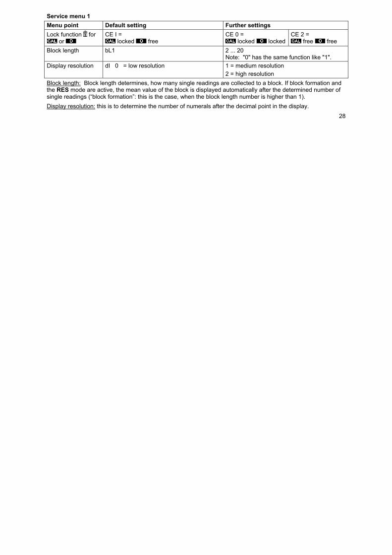
Service menu 1 Menu point Default setting Further settings Lock function for
or CE I =
locked free CE 0 =
locked locked CE 2 =
free free
Block length bL1 2 ... 20 Note: "0" has the same function like "1".
Display resolution dI 0 = low resolution 1 = medium resolution 2 = high resolution
Block length: Block length determines, how many single readings are collected to a block. If block formation and the RES mode are active, the mean value of the block is displayed automatically after the determined number of single readings (“block formation”: this is the case, when the block length number is higher than 1). Display resolution: this is to determine the number of numerals after the decimal point in the display.

29
Service menu 2 "Radio transmission"
Menu point Default setting Further settings SubNet number nN 0 0 ... 15 Instrument number within the SubNet
nr 0 0 ... 15
Repeat specification nP 1 0 ... 7 SubNet Number: this no. specifies a certain group of MP0R instruments, which are assigned to common radio receiver. This allows to distinguish this certain group from other instrument groups with radio transmission. Instrument number within the SubNet: this number identifies a single MP0R instrument within a subnet group. Repeat specification: a signal can be sent repeatedly to allow a transfer check. The set rate is the same as the number of repetitions.

30
Service menu 3 Menu point Default setting Further settings
Dimension unit UN = µm NILS = mils
Measuring program r 00 = display of coating thickness reading r 01 = display of the normalized probe output signal Xn (normalized countrate) (for service purposes only!)
r 02 = display of the measured probe output signal X (countrate) (for service purposes only!)

31
Menu point Default setting Further settings Acoustical signal bepI = beep sound ON bep0 = beep sound OFF Measuring mode (only displayed with Dualscope instr.)
dual = automatic selection between magnetic induction method and Eddy current method
Fe = measurements with magnetic induction method only NF = measurements with Eddy current method only
Radio transmission rF I = radio transmission ON rF 0 = radio transmission OFF Radio transmission in the continuous mode (for service purposes only)
FrL I = radio transmission in the continuous mode ON
FrL0 = radio transmission in the continuous mode OFF Assumption for the operation in the continuous mode: radio transmission is OFF. See “Measuring in the continuous mode” in menu 5.

32
Service menu 4 Menu point Default setting Further settings Single reading transmission / Mean value transmission
SI I Each single reading will be transmitted to the PC
SI 0 Mean values only will be transmitted to the PC
Group separation GS I Group separation ON GS 0 Group separation OFF Auto switching-off OFFI
short switch-off time approx. 1 minute OFF2 long switch-off time approx. 5 minutes
Display lighting ELI Display lighting ON
EL0 Display lighting OFF
Group separation: The end of a block can be marked with a group separator. The group separator can be transferred to the computer together with the readings.

33
Service menu 5 Menu point Meaning Measuring in the continuous mode
Assumption for the operation in the continuous mode: “Radio transmission in the „continuous mode” is OFF (see service menu 3 “FrL0”) Continuous mode ON: call service menu 5 Continuous mode OFF: call service menu 5 again Note: At the end of the operation with the MP0R instrument, always switch OFF the continuous mode! Otherwise the batteries will go empty (Auto-switch-off doesn’t work in the continuous mode!)
Service menu 10 Menu point Meaning Master calibration UCAL (for service purposes only!)

34
15 Trouble Shooting Message Explanation / Possible Cause Solution Er1 Internal error Perform a normalization. If the error occurs
repeatedly, call the Fischer service dpt. Er4 Overflow of the data memory Delete the data memory. Er5 Cannot determine value for substrate material. Perform calibration on coating using a suitable
calibration standard. The selected calibration standard should have at least 50% of the coating thickness of the coated specimen (this refers to the specimen that is used for the calibration on the coating).

35
Message Explanation / Possible Cause Solution Er6
Reading cannot be displayed since it is out of the measuring range. Cause: coating is too thick. Cause: measurement was not performed correctly Cause: erroneous normalization or calibration
Perform measurements on a specimen having a coating thickness measurable by the instrument. Perform measurements correctly (e.g. do not hover with the instrument over the specimen before or after the measurement or do not lift off the instrument from the specimen too swiftly after the measurement).
Er7 (continued on next page)
Outlier measurement was recognized during normalization or calibration - measurement on the calibration standard was not performed correctly.
Delete memory and perform new test series. Repeat normalization or calibration correctly (e.g. do not hover with the instrument or do not lift off the instrument too swiftly after the meas.

36
- measurement was performed on a the cal. standard instead of the uncoated specimen. - measurement on a creased cal. standard. - measurement was not performed with the instrument placed squarely on the specimen or the calibration standard.
Perform all measurements for the normalization using a mean value on the same specimen. Replace calibration standard. Perform all measurements correctly with the instrument placed squarely on the specimen or the calibration standard.
Er12 Calibration standards measured in wrong sequence during the calibration.
Repeat the calibration in the correct sequence.
Er13 (continued on next page)
Readings of the calibration standard are not in the admissible interval range of the master calibration. Used wrong calibration standards.
Inform customer service.
Use correct calibration standards.

37
Normalization performed by mistake on calibration standard instead of on uncoated specimen.
Perform normalization on uncoated specimen.
Er14 Internal instrument error: Not able to compute master characteristic. The original master characteristic is retained.
Repeat master calibration. If this error occurs repeatedly: Contact customer service.
Er15 Not able to save the master characteristic. Probe may be defective.
Contact customer service.
Er17 Not enough readings. Thus, not able to finish a block (applies to measurements w. fixed block limits). While calibration: STD1 has been measured only once.
Make additional measurements until the first block can be finished. Then generate a new final result. While calibration: STD1 has to be measured for approx. 5 times.

38
Er22 Internal instrument error. Error accessing the measurement memory or. EEPROM.
Contact customer service.
Er28 Internal instrument error: Not able to compute measurement.
Contact customer service.
Er29 A locked function has been called ( or ).
Set the function free again in service menu 1.

39
16 Technical data Instrument model DUALSCOPE® MP0R USB
DUALSCOPE® MP0R-FP USB ISOSCOPE® MP0R USB
Part no. standard version MP0R USB: 604-048 (MP0R-FP: 604-049) 604-063 Part no. US version MP0R USB: 604-051 (MP0R-FP: not available) 604-066 Coatings that can be measured (test methods)
NF, Iso/Fe Non-magnetic coatings or isolating coatings on steel or iron (Magnetic induction method) Iso/NF Isolating coatings on nonferrous metals (Eddy current method)
Iso/NF Isolating coatings on nonferrous metals (Eddy current method)

40
Instrument model DUALSCOPE® MP0R(-FP) USB ISOSCOPE® MP0R USB Measurement ranges NF,Iso/Fe 0 - 2000 µm (0 - 78 mils)
Iso/NF 0 - 2000 µm (0 - 78 mils) Iso/NF 0 - 1200 µm (0 - 48 mils)
Trueness based on Fischer standards
0 ... 75 µm (0 - 3 mils) 1.5 µm75 ... 1000 µm (2 - 39 mils) 2 % 1000 ... 2000 µm (40 - 78 mils) up to 3 %
0 ... 100 µm (0 - 4 mils) 1 µm 100 ... 500 µm (4 - 20 mils) 1 % 500 ... 1200 µm (20 - 48 mils) up to 2 %
Repeatability precision based on Fischer standards
0 ... 50 µm (0 - 2 mils) 0.5 µm50 ... 1000 µm (2 - 39 mils) 1 % 1000 ... 2000 µm (40 - 78 mils) up to 1.5 %
0 ... 100 µm (0 - 4 mils) 0.5 µm 100 ... 500 µm (4 - 20 mils) 0.5 % 500 ... 1200 µm (19.7-48 mils) up to 1 %
Weight 60 g (2.12 oz) (without batteries) Dimensions W x D x H: 64 x 30 x 85 mm (2.5” x 1.2” x 3.4”)

41
Power supply 2 x LR6.AA Power consumption Max. 0.2 Watt Permissible ambient temp. 5 ... 40°C (41 – 104°F) during operation; storage temp.: 5... 60°C (41 – 140°F) Permissible rel. humidity 30 ... 90 % (non-condensing) Radio communication Radio transmitter 868 MHz or 915 MHz (US-version) for the unidirectional transmission of
measurement data to an external computer (cf. order information next chapter). Transmitting power 25 mW standard USB data communication Bi-directional communication from MP0R instrument to a PC via optional interface cable Measurement data memory
A maximum of 999 measurement readings can be combined in one block. The memory contents are retained even without power supply.
Minimum meas. interval 2 seconds minimum duration between two measurements
42
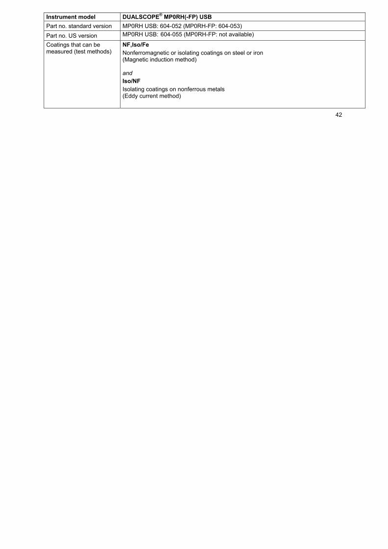
Instrument model DUALSCOPE® MP0RH(-FP) USB Part no. standard version MP0RH USB: 604-052 (MP0RH-FP: 604-053) Part no. US version MP0RH USB: 604-055 (MP0RH-FP: not available) Coatings that can be measured (test methods)
NF,Iso/Fe Nonferromagnetic or isolating coatings on steel or iron (Magnetic induction method) and Iso/NF Isolating coatings on nonferrous metals (Eddy current method)

43
Instrument model DUALSCOPE® MP0RH-FP USB Measurement ranges NF,Iso/Fe 0 - 7000 µm (0 - 275 mils)
Iso/NF 0 - 2000 µm (0 - 80 mils) Trueness based on Fischer standards
NF,Iso/Fe 0 ... 50 µm (0 - 2 mils) 2 µm50 ... 2000 µm (2 - 80 mils) 4 %2000 ... 7000 µm (80 - 275 mils) up to 6 %
Iso/NF 0 ... 50 µm (0 - 2 mils) 1 µm50 ... 1000 µm (2 - 40 mils) 2 %1000 ... 2000 µm (40 - 80 mils) up to 3 %
44
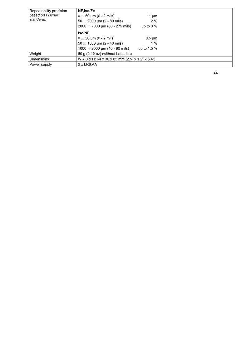
Repeatability precision based on Fischer standards
NF,Iso/Fe 0 ... 50 µm (0 - 2 mils) 1 µm50 ... 2000 µm (2 - 80 mils) 2 %2000 ... 7000 µm (80 - 275 mils) up to 3 %
Iso/NF 0 ... 50 µm (0 - 2 mils) 0.5 µm50 ... 1000 µm (2 - 40 mils) 1 %1000 ... 2000 µm (40 - 80 mils) up to 1.5 %
Weight 60 g (2.12 oz) (without batteries) Dimensions W x D x H: 64 x 30 x 85 mm (2.5” x 1.2” x 3.4”) Power supply 2 x LR6.AA

45
Power consumption Max. 0.2 Watt Permissible ambient temp. 5 ... 40°C (41 – 104°F) during operation; storage temp. 5 ... 60°C (41 - 140°F) Permissible rel. humidity 30 ... 90 % (non-condensing) Communication Radio transmitter 868 MHz or 915 MHz (US-version) for the unidirectional transmission of
measurement data to an external computer (cf. order information next chapter). Transmitting power 25 mW standard USB data communication Bi-directional communication from MP0R instrument to a PC via optional interface cable Measurement data memory
A maximum of 999 measurement readings can be combined in one block. The memory contents are retained even without power supply.
Minimum meas. interval 2 seconds minimum duration between two measurements.

46
17 Order information for instruments and accessories Item Part no. DUALSCOPE MP0R USB 604-048 (incl. standard accessories) DUALSCOPE MP0R-US USB 604-051 (incl. standard accessories) ISOSCOPE MP0R USB 604-063 (incl. standard accessories) ISOSCOPE MP0R-US USB 604-066 (incl. standard accessories) Radio receiver USB RS232 868 MHz 604-044 DUALSCOPE MP0RH USB 604-052
Item Part no. DUALSCOPE MP0RH-US USB 604-055 Radio receiver-US USB RS232 915 MHz 604-045Carrying loop MP0R 603-481 Calibration standard 75 µm 603-479 Software PC-DATEX 602-465 Protective cover MP0R 603-582 Calibration standard 75 µm plastic MP0R 603-479 Calibration standard Al-Base MP0R 603-478 Calibration standard Fe-Base MP0R 603-477