Embed Size (px)
Citation preview
Publication X30024©CONTINENTAL MOTORS, INC. AUGUST 2011
IO-470
CONTINENTAL® AIRCRAFT ENGINE
OPERATOR’SMANUAL
FAA APPROVED
A IO-470 Series Engine Operator’s Manual31 August 2011
Supersedure Notice
This manual revision replaces the front cover and list of effective pages for Publication Part No. X30024, dated June 1973. Previous editions are obsolete upon release of this manual.
Effective Changes for this Manual0....................... June 19731............... 31 August 2011
List of Effective Pages
Document Title:IO-470 Series Engine Operator’s ManualPublication Number: X30024 Initial Publication Date: June 1973 Page Change Page Change Page Change Page ChangeCover ..............................1A......................................1i thru vi ............................01 thru 41..........................042 Blank added...............1
Published and printed in the U.S.A. by Continental Motors, Inc.
Available exclusively from the publisher: P.O. Box 90, Mobile, AL 36601.
Copyright © 2011 Continental Motors, Inc. All rights reserved. This material may not be reprinted, republished, broadcast, or otherwise altered without the publisher's written permission. This manual is provided without express, statutory, or implied warranties. The publisher will not be held liable for any damages caused by or alleged to be caused by use, misuse, abuse, or misinterpretation of the contents. Content is subject to change without notice. Other products and companies mentioned herein may be trademarks of the respective owners.

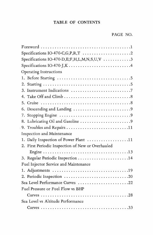
TABLE OF CONTENTS
PAGE NO.
Foreword .............. , ........................ 1
Specifications IO-470-C,G,P,R,T ..................... 2
Specifications IO-470-D,E;F,H,L,M,N,S,U,V ............ 3
Specifications IO-470-J,K .......................... .4
Operating Instructions
1. Before Starting ................................ 5
2. Starting ...................................... 5
3. Instrument Indications .......................... 7
4. Take Off and Climb ............................. 8
5. Cruise ....................................... 8
6. Descending and Landing ......................... 9
7. Stopping Engine ............................... 9
8. Lubricating Oil and Gasoline ...................... 9
,9. Troubles and Repairs ........................... 11
Inspection and Maintenance
1. Daily Inspection of Power plant .................. 11
2. First Periodic Inspection of New or Overhauled
Engine ..................................... 13
3. Regular Periodic Inspection ..... ' ................. 14
Fuel Injector Service and Maintenance
1. Adjustments ..........................•...... 19
2. Periodic Inspection .................... ; ....... 20
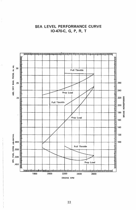
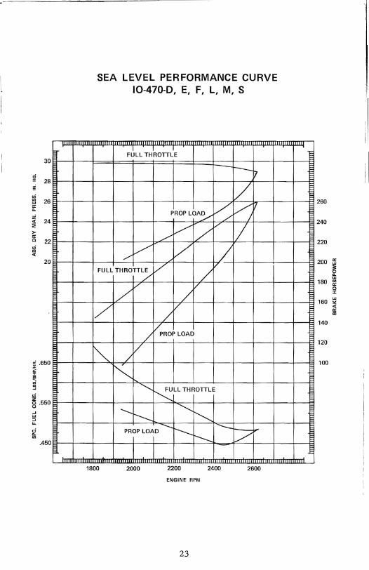
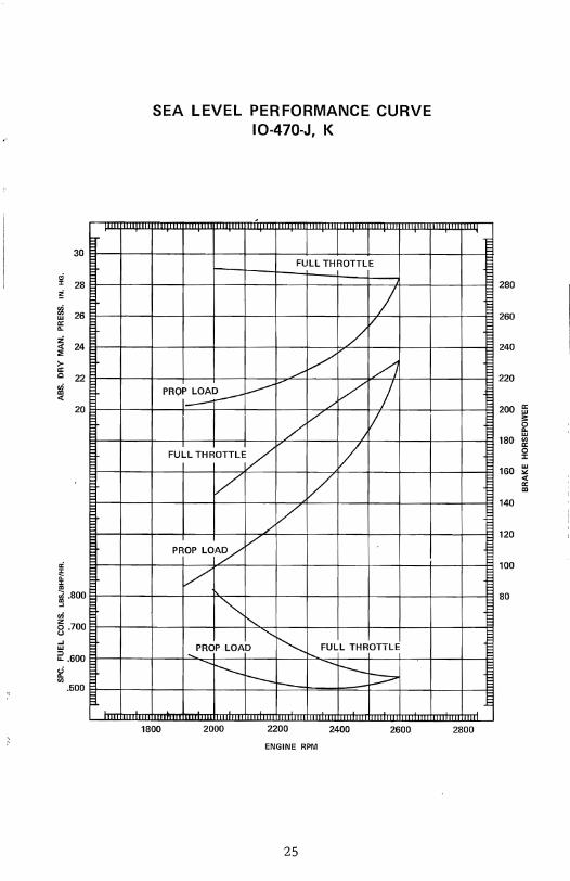
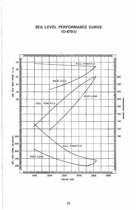
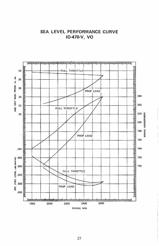
Sea Level Performance Curves ...................... 22
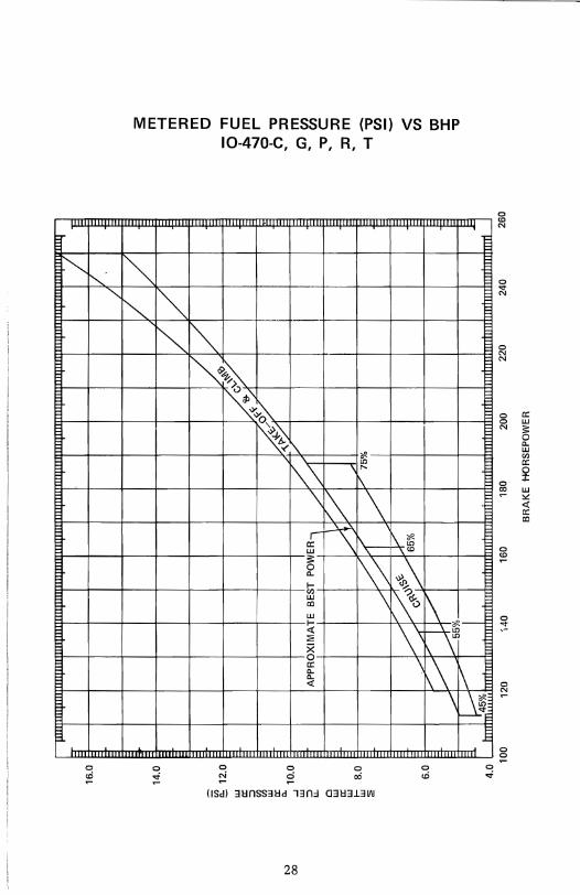
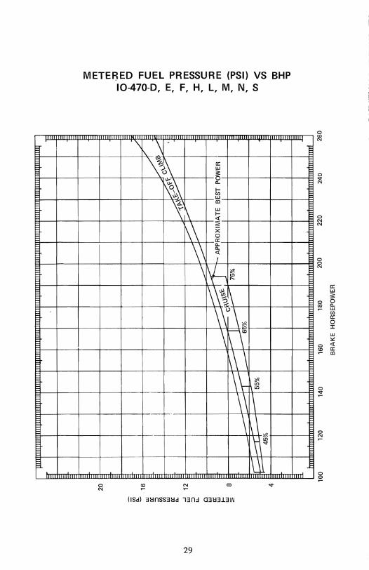
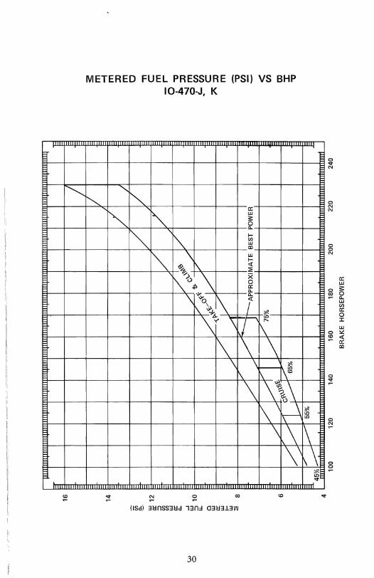
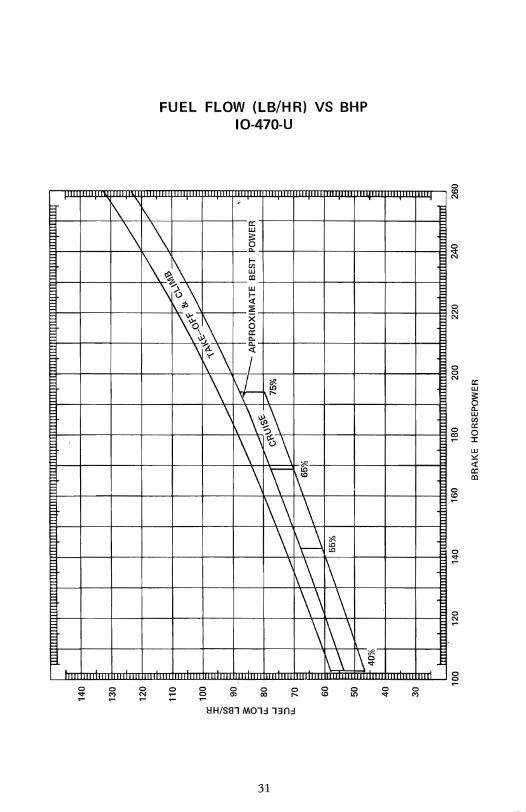
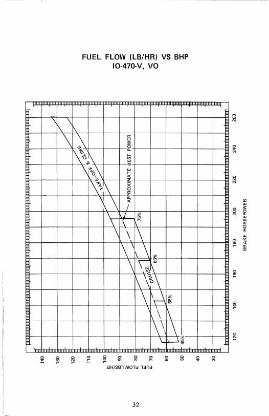
Fuel Pressure or Fuel Flow vs BHP
Curves ...................................... 28
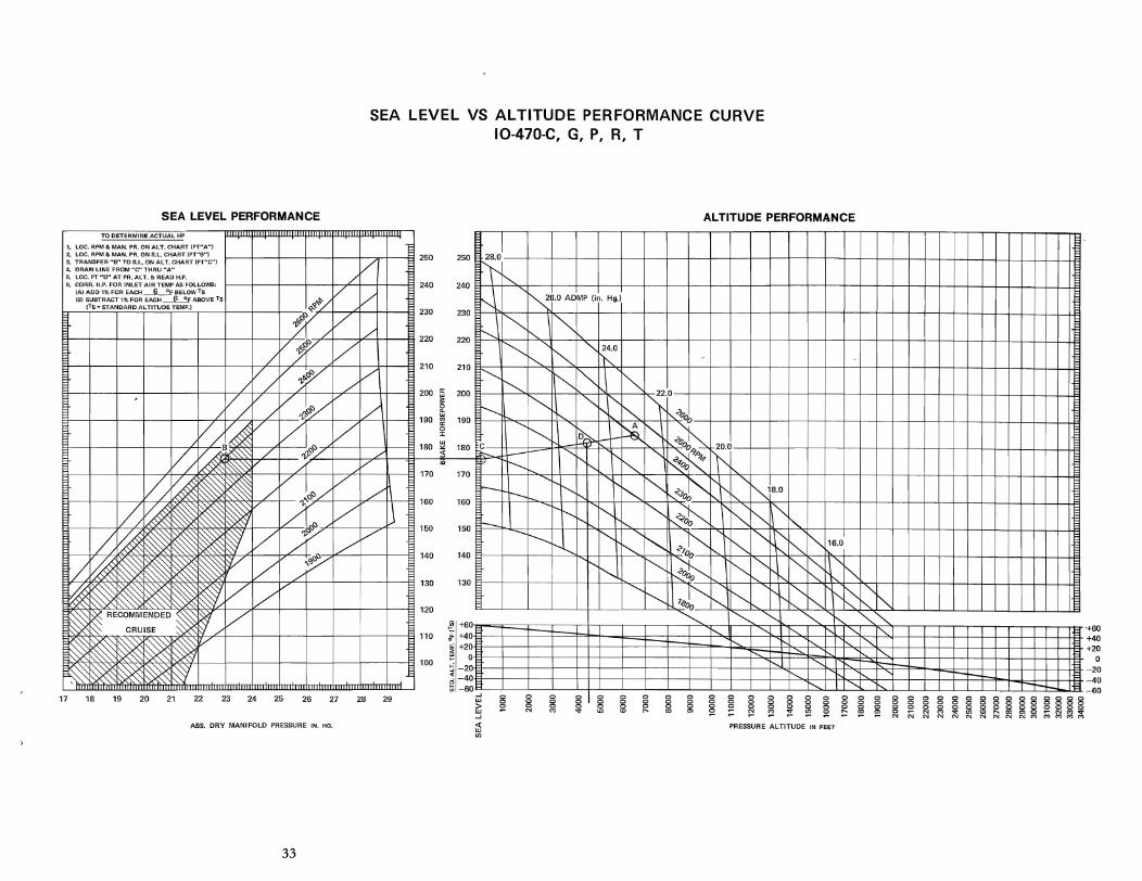
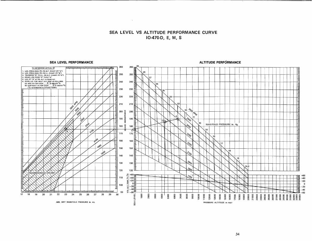
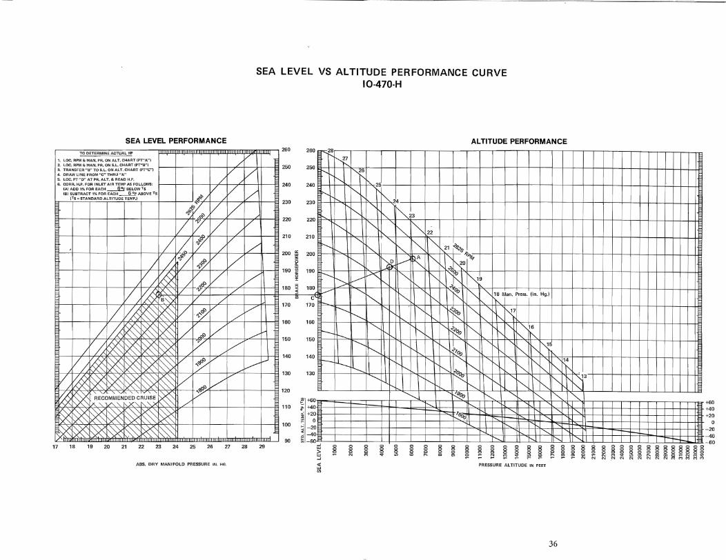
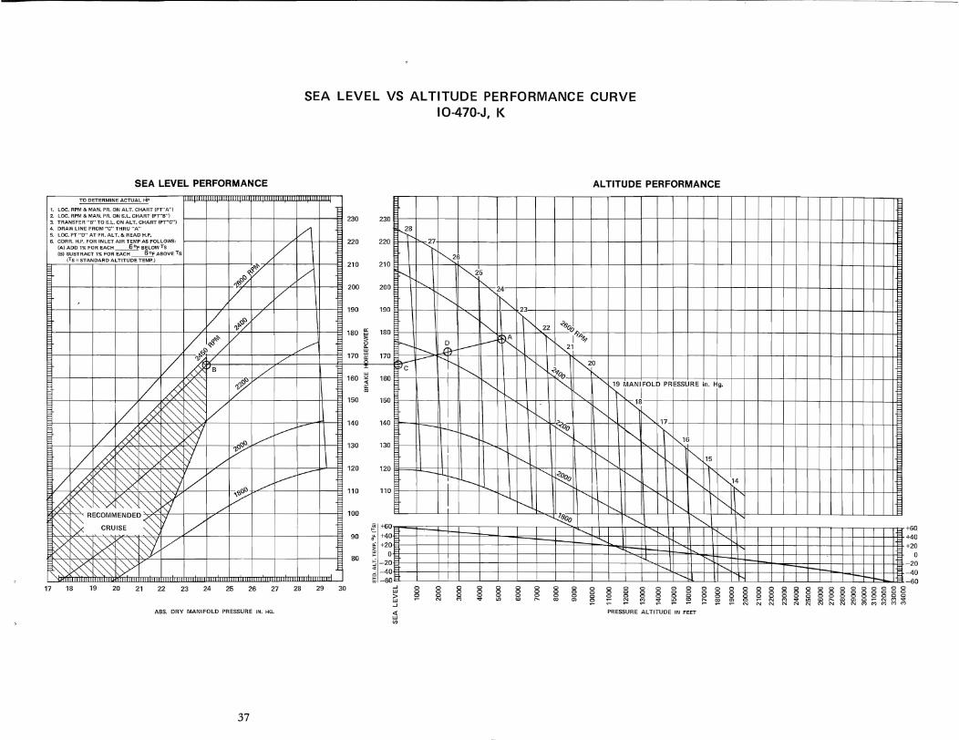
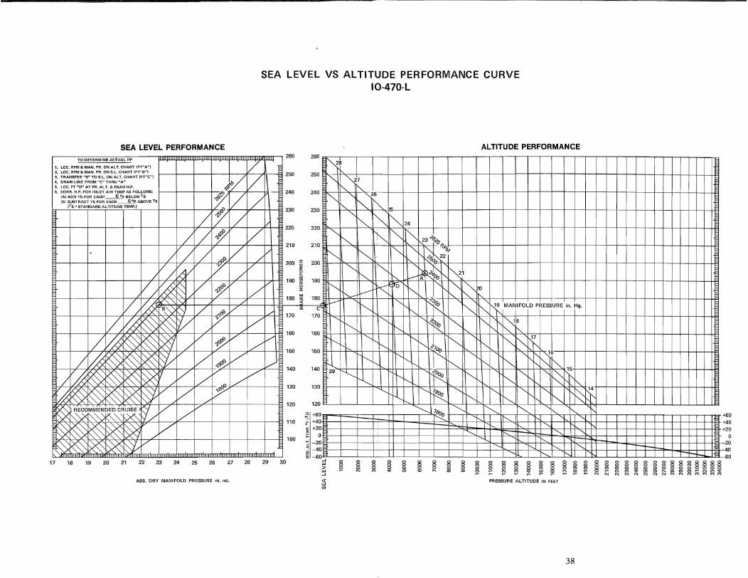
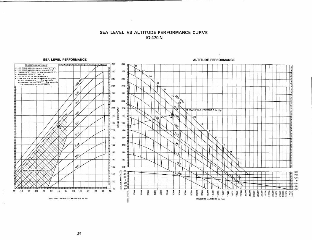
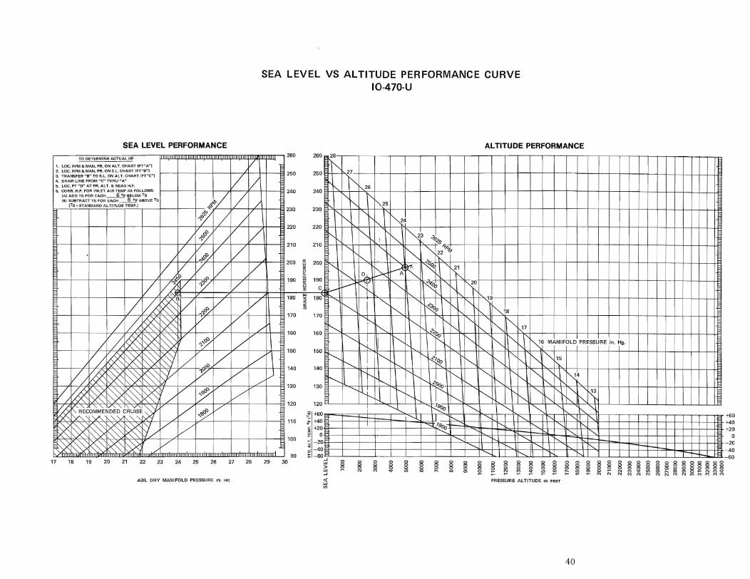
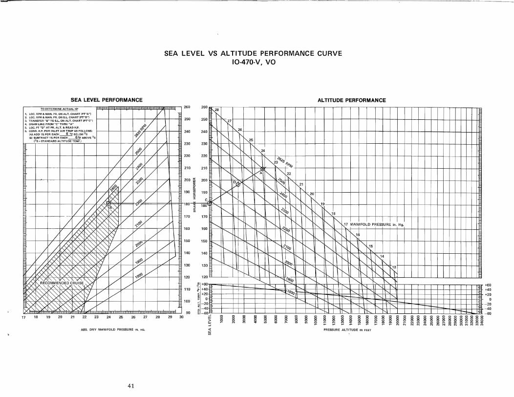
Sea Level vs Altitude Performance
Curves ...................................... 33
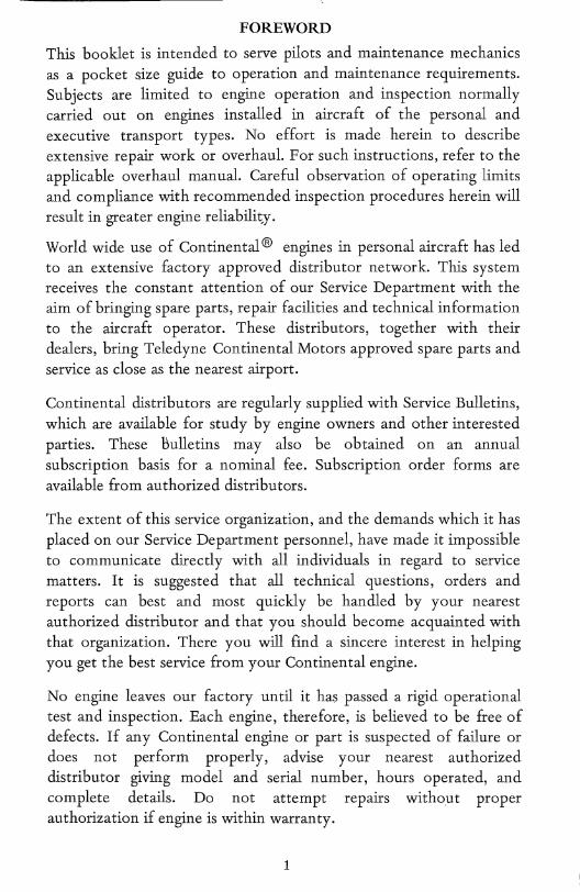
FOREWORD This booklet is intended to serve pilots and maintenance mechanics as a pocket size guide to operation and maintenance requirements. Subjects are limited to engine operation and inspection normally carried out on engines installed in aircraft of the personal and executive transport types. No effort is made herein to describe extensive repair work or overhaul. For such instructions, refer to the applicable overhaul manual. Careful observation of operating limits and compliance with recommended inspection procedures herein will result in greater engine reliabilit.y.
World wide use of Continental ® engines in personal aircraft has led to an extensive factory approved distributor network. This system receives the constant attention of our Service Department with the aim of bringing spare parts, repair facilities and technical information to the aircraft operator. These distributors, together with their dealers, bring Teledyne Continental Motors approved spare parts and service as close as the nearest airport.
Continental distributors are regularly supplied with Service Bulletins, which are available for study by engine owners and other interested parties. These bulletins may also be obtained on an annual subscription basis for a nominal fee. Subscription order forms are available from authorized distributors.
The extent of this service organization, and the demands which it has placed on our Service Department personnel, have made it impossible to communicate directly with all individuals in regard to service matters. It is suggested that all technical questions, orders and reports can best and most quickly be handled by your nearest authorized distributor and that you should become acquainted with that organization. There you will find a sincere interest in helping you get the best service from your Continental engine. ~
No engine leaves our factory until it has passed a rigid operational test and inspection. Each engine, therefore, is believed to be free of defects. If any Continental engine or part is suspected of failure or does not perform properly, advise your nearest authorized distributor giving model and serial number, hours operated, and complete details. Do not attempt repairs without proper authorization if engine is within warranty.
1
-~--l
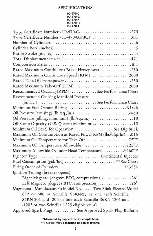
SPECIFICATIONS 10-470-C 10-470-G 10-470-P 10-470-R 10-470-T
Type Certificate Number - IO-470-C ...................... 273 Type Certificate Number - IO-470-G,P,R,T ................ 3El Number of Cylinders .......................... ; ......... 6 Cylinder Bore (inches) ................................... 5 Piston Stroke (inches) .................................. .4 Total Displacement (cu. in.) .. -.......................... .471 Compression Ratio ................. ' ................... 8: 1 Rated Maximum Continuous Brake Horsepower ............. 250 Rated Maximum Continuous Speed (RPM) ................ 2600 Rated Take-Off Horsepower ............................. 250 Rated Maximum Take-Off (RPM) ....................... 2600 Recommended Cruising (RPM) ........... See Performance Chart Recommended Cruising Manifold Pressure
(in. Hg.) ......................... See Performance Chart Minimum Fuel Octane Rating ......................... 91/96 Oil Pressure (cruising) (lb./sq./in.) ...................... 30-60 oil Pressure (idling, minimum) (lb./sq./in.) .................. 10 Oil Sump Capacity (U.S. Quarts) Maximum .................. 12 Minimum Oil Level for Operation ................ See Dip Stick Maximum Oil Consumption at Rated Power RPM (lbs/bhp/hr) .. 015 MinimumOil Temperature for Take-Off .................. 75°F Maximum Oil Temperature Allowable ................... 225° F Maximum Allowable Cylinder Head Temperature ......... *460° F Injector Type ........................... Continental Injector Fuel Consumption (gal./hr.) ...................... **See Chart Firing Order of Cylinders ............................ 163254 Ignition Timing (breaker opens)
Right Magneto (degrees BTC, compression) .... ~ ........ 26° Left Magneto (degrees BTC, compression) ......... : .... 26°
Magnetos: Manufacturer's Model No ..... Two Slick Electro Model 662 or 680 or Scintilla S6RN-25 or one each Scintilla S6RN-201 and -205 or one each Scintilla S6RN-1201 and -1205 or two Scintilla 1225 eligible on -C. "
Approved Spark Plugs ......... See Approved Spark Plug Bulletin
*Measured by tapped thermocouple boss. **This will vary according to power setting.
2
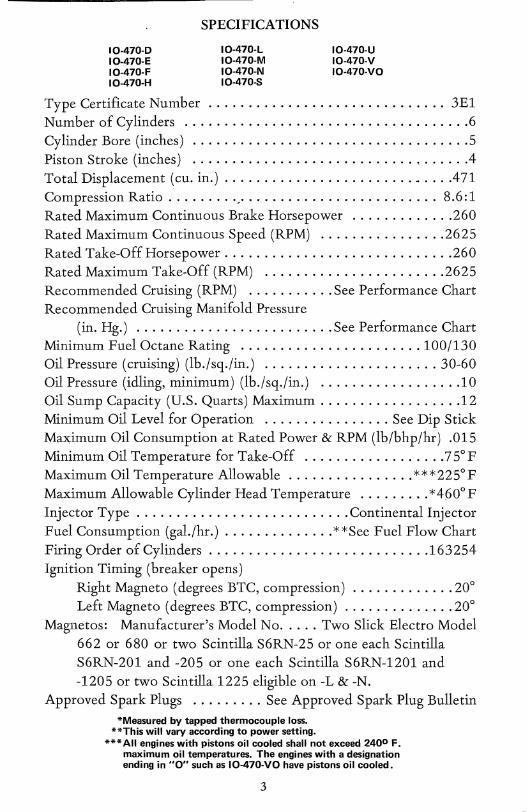
SPECIFICATIONS
10.470·0 10·470·L 10.470·E 10·470·M 10.470·F 10·470·N 10-470·H 10·470-8
10·470·U 10-470·V 10-470·VO
Type Certificate Number .............................. 3E1 Number of Cylinders .................................... 6 Cylinder Bore (inches) ................................... 5 Piston Stroke (inches) ............................ , ..... .4 Total Displacement (cu. in.) ........................ _ ... .471 Compression Ratio ........ ',' ........................ 8.6:1 Rated Maximum Continuous Brake Horsepower ............. 260 Rated Maximum Continuous Speed (RPM) ................ 2625 Rated Take-Off Horsepower ............................. 260 Rated Maximum Take-Off (RPM) ....................... 2625 Recommended Cruising (RPM) ........... See Performance Chart Recommended Cruising Manifold Pressure
(in. Hg.) ......................... See Performance Chart Minimum Fuel Octane Rating ....................... 100/130 oil Pressure (cruising) (lb./ sq .lin.) ...................... 30-60 Oil Pressure (idling, minimum) (lb./sq./in.) , ................. 10 Oil Sump Capacity (U.S. Quarts) Maximum .................. 12 Minimum Oil Level for Operation ................ See Dip Stick Max;imum Oil Consumption at Rated Power & RPM (lb/bhp/hr) .015 Minimum oil Temperature for Take-Off .................. 75° F Maximum Oil Temperature Allowable ................ ***225°F Maximum Allowable Cylinder Head Temperature ......... *460° F Injector Type ........................... Continental Injector Fuel Consumption (gal./hr.) .............. **See Fuel Flow Chart Firing Order of Cylinders ............................ 163254 Ignition Timing (breaker opens)
Right Magneto (degrees BTC, compression) ............. 20° Left Magneto (degrees BTC, compression) .............. 20°
Magnetos: Manufacturer's Model No ..... Two Slick Electro Model 662 or 680 or two Scintilla S6RN-25 or one each Scintilla S6RN-201 and -205 or one each Scintilla S6RN-1201 and -1205 or two Scintilla 1225 eligible on -L & -N.
Approved Spark Plugs ......... See Approved Spark Plug Bulletin *Measured by tapped thermocouple loss.
**This will vary according to power setting. *** All engines with pistons oil cooled shall not exceed 2400 F.
maximum oil temperatures. The engines with a designation ending in "0" such as 10-470·VO have pistons oil cooled.
3
l
SPECIFICATIONS
IO-470-J IO-470'K
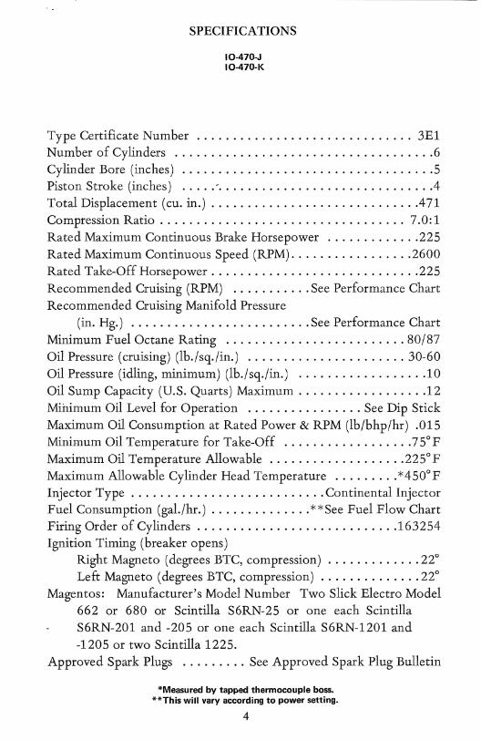
Type Certificate Number .............................. 3El Number of Cylinders .................................... 6 Cylinder Bore (inches) ................................... 5 Piston Stroke (inches) ..... ' ............................. .4 Total Displacement (cu. in.) ............................ .471 Compression Ratio .................................. 7.0: 1 Rated Maximum Continuous Brake Horsepower ............. 225 Rated Maximum Continuous Speed (RPM) ................. 2600 Rated Take-Off Horsepower ............................. 225 Recommended Cruising (RPM) ........... See Performance Chart Recommended Cruising Manifold Pressure
(in. Hg.) ......................... See Performance Chart Minimum Fuel Octane Rating ......................... 80/87 oil Pressure (cruising) (lb./sq./in.) ...................... 30-60 Oil Pressure (idling, minimum) (lb./sq./in.) .................. 10 Oil Sump Capacity (U.S. Quarts) Maximum .................. 12 Minimum oil Level for Operation ................ See Dip Stick Maximum Oil Consumption at Rated Power & RPM (lb/bhp/hr) .015 Minimum oil Temperature for Take-Off .................. 75° F Maximum oil Temperature Allowable ................... 225°F Maximum Allowable Cylinder Head Temperature ......... *450°F Injector Type ........................... Continental Injector Fuel Consumption (gal./hr.) .............. **See Fuel Flow Chart Firing Order of Cylinders ............................ 163254 Ignition Timing (breaker opens)
Right Magneto (degrees BTC, compression) ............. 22° Left Magneto (degrees BTC, compression) .............. 22°
Magentos: Manufacturer's Model Number Two Slick Electro Model 662 or 680 or Scintilla S6RN-25 or one each Scintilla S6RN-201 and -205 or one each Scintilla S6RN-1201 and -1205 or two Scintilla 1225.
Approved Spark Plugs ......... See Approved Spark Plug Bulletin
*Measured by tapped thermocouple boss. **This will vary according to power setting.
4
OPERATING INSTRUCTIONS
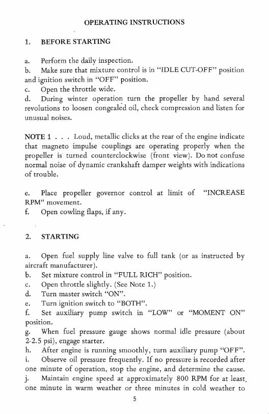
1. BEFORE STARTING
a. Perform the daily inspection. b. Make sure that mixture control is in "IDLE CUT-OFF" position and ignition switch in "OFF" position. c. Open the throttle wide. d. During winter operation turn the propeller by hand several revolutions to loosen congeal~d oil, check compression and listen for unusual noises.
NOTE 1 . . . Loud, metallic clicks at the rear of the engine indicate that magneto impulse couplings are operating properly when the propeller is' turned counterclockwise (front view). Do not confuse normal noise of dynamic crankshaft damper weights with indications of trouble.
e. place propeller governor control at. limit of "INCREASE RPM" movement. f. Open cowling flaps, if any.
2. STARTING
a. Open fuel supply line valve to full tank (or as instructed by aircraft manufacturer). b. Set mixture control in "FULL RICH" position. c. Open throttle slightly. (See Note 1.) d. Turn master switch "ON". e. Turn ignition switch to "~OTH". f. Set auxiliary pump switch in "LOW" or "MOMENT ON" position. g. When fuel pressure gauge shows normal idle pressure (about 2-2.5 psi), engage starter. h. After engine is running smoothly, turn auxiliary pump "OFF". i. Observe oil pressure frequently. If no pressure is recorded,after one minute of operation, stop the engine, and determine the cause. j. Maintain engine speed at approximately 800 RPM for at least, one minute in warm weather or three minutes in cold weather to
5
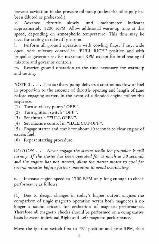
prevent cavitation in the pressure oil pump (unless the oil supply has been diluted or preheated.) k. Advance throttle slowly until tachometer indicates approximately 1200 RPM. Allow additional warm-up time at this speed, depending on atmospheric temperature. This time may be used for taxiing to take-off position. 1. Perform all ground operation with cowling flaps, if any, wide open, with mixture control in "FULL RICH" position and with propeller governor set for maximum RPM except for brief testing of mixture and governor controls: m. Restrict ground operation to the time necessary for warm-up and testing.
NOTE 2 . . . The auxiliary pump delivers a continuous flow of fuel in proportion to the amount of throttle opening and length of time before engaging starter. In the event of a flooded engine follow this sequence. (1) Turn auxiliary pump "OFF". (2) Turn ignition switch "OFF". (3) Set throttle "FULL OPEN". (4) Set mixture control in "IDLE CUT-OFF". (5) Engage starter and crank for about 1 0 seconds to clear engine of excess fuel. (6) Repeat starting procedure.
CA UTION ... Never engage the starter while the propeller is still turning. If the starter has been operated for as much as 30 seconds and the engine has not started, allow the starter motor to cool for several minutes before further operation to avoid overheating.
n. Increase engine speed to 1700 RPM only long enough to check performance as follows:
(1) Due to design changes in today's higher output engines the comparison of single magneto operation versus both magnetos is no longer a sound criteria for evaluation of magneto performance. Therefore all magneto checks should be performed on a comparative basis between individual Right and Left magneto performance.
Move the ignition switch first to "R" position and note RPM, then
6
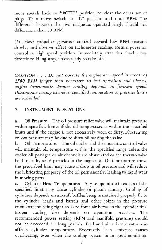
move switch back to "BOTH" posltlOn to clear the other set of plugs. Then move switch to "L" position and note RPM. The difference between the two magnetos operated singly should not differ more than 50 RPM.
(2) Move propeller governor control toward low RPM posltlOn slowly, and observe effect on tachometer reading. Return governor control to high speed position. Immediately after this check close throttle to idling stop, unless r~ady to take-off.
CA UTION . . . Do not operate the engine at a speed in excess of 1500 RPM longer than necessary to test operation and observe engine instruments. Proper cooling depends on forward speed. Discontinue testing whenever specified temperature or pressure limits are exceeded.
3. INSTRUMENT INDICATIONS
a. Oil Pressure: The oil pressure relief valve will maintain pressure within specified limits if the oil temperature is within the specified limits and if the engine is not excessively worn or dirty. Fluctuating or low pressure may be due to dirty oil passing the valve. b. oil Temperature: The oil cooler and thermostatic control valve will maintain oil temperature within the specified range unless the cooler oil passages or air channels are obstructed or the thermo valve held open by solid particles in the engine oil. oil temperature above the prescribed limit may cause a drop in oil pressure and will reduce the lubricating property of the oil permanently, leading to rapid wear in moving parts. c. Cylinder Head Temperature: Any temperature in excess of the specified limit may cause cylinder or piston damage. Cooling of cylinders depends on aircraft baffles being maintained properly fit to the cylinder heads and barrels and other joints in the pressure compartment being tight so as to force air between the cylinder fins. Proper cooling also depends on operation practices. The recommended power setting (RPM and manifold pressure) should not be exceeded for long periods. Fuel and air mixture ratio also affects cylinder temperature. Excessively lean mixture causes overheating, even when the cooling system is in good condition.
7
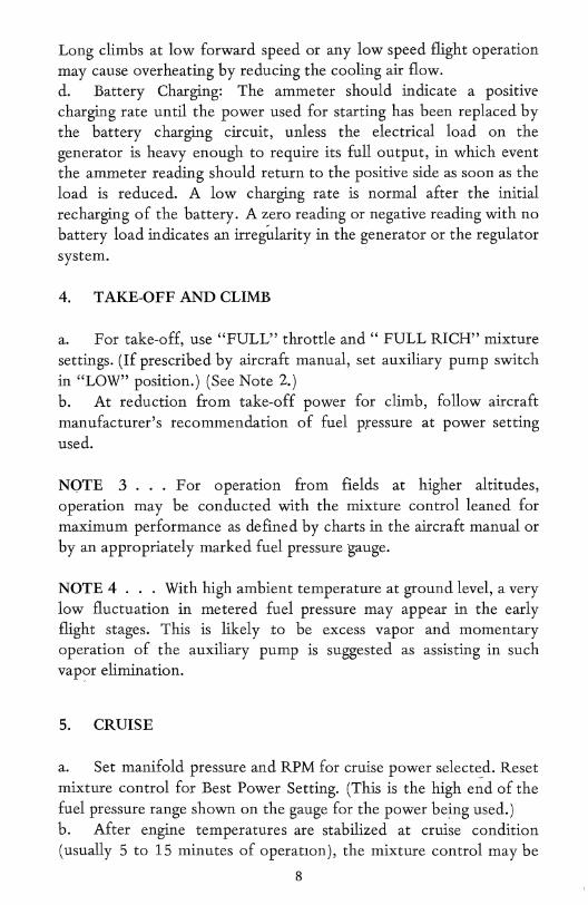
Long climbs at low forward speed or any low speed flight operation may cause overheating by reducing the cooling air flow. d. Battery Charging: The ammeter should indicate a positive charging rate until the power used for starting has been replaced by the battery charging circuit, unless the electrical load on the generator is heavy enough to require its full output, in which event the ammeter reading should return to the positive side as soon as the load is reduced. A low charging rate is normal after the initial recharging of the battery. A zero reading or negative reading with no battery load indicates an irregirlarity in the generator or the regulator system.
4. TAKE-OFF AND CLIMB
a. For take-off, use "FULL" throttle and " FULL RICH" mixture settings. (If prescribed by aircraft manual, set auxiliary pump switch in "LOW" position.) (See Note 2.) b. At reduction from take-off power for climb, follow aircraft manufacturer's recommendation of fuel pressure at power setting used.
NOTE 3 ... For operation from fields at higher altitudes, operation may be conducted with the mixture control leaned for maximum performance as defined by charts in the aircraft manual or by an appropriately marked fuel pressure gauge.
NOTE 4 . . . With high ambient temperature at ground level, a very low fluctuation in metered fuel pressure may appear in the early flight stages. This is likely to be excess vapor and momentary operation of the auxiliary pump is suggested as assisting in such vap?r elimination.
5. CRUISE
a. Set manifold pressure and RPM for cruise power selected. Reset mixture control for Best Power Setting. (This is the high e~d of the fuel pressure range shown on the gauge for the power being used.) b. After engine temperatures are stabilized at cruise condition (usually 5 to 15 minutes of operatlOn), the mixture control may be
8
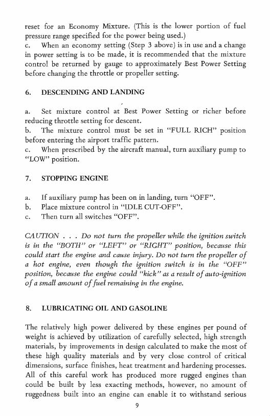
reset for an Economy Mixture. (This is the lower portion of fuel pressure range specified for the power being used.) c. When an economy setting (Step 3 above) is in use and a change in power setting is to be made, it is recommended that the mixture control be returned by gauge to approximately Best Power Setting before changing the throttle or propeller setting.
6. DESCENDING AND LANDING
a. Set mixture control at Best Power Setting or richer before reducing throttle setting for descent. b. The mixture control must be set in "FULL RICH" position before entering the airport traffic pattern. c. When prescribed by the aircraft manual, turn auxiliary pump to "LOW" position.
7. STOPPING ENGINE
a. If auxiliary pump has been on in landing, turn "OFF". b. Place mixture control in "~DLE CUT-OFF". c. Then turn all switches "OFF".
CA UTION . . . Do not turn the propeller while the ignition switch is in the "BOTH" or "LEFT" or "RIGHT" position, because this could start the engine and cause injury. Do not turn the propeller of a hot engine, even though the ignition switch is in the "OFF" position, because the engine could "kick" as a result of auto-ignition of a small amount of fuel remaining in the engine.
8. LUBRICATING OIL AND GASOLINE
The relatively high power delivered by these engines per pound of weight is achieved by utilization of carefully selected, high strength materials, by improvements in design calculated to make the most of these high quality materials and by very close control of critical dimensions, surface finishes, heat treatment and hardening processes. All of this careful work has produced more rugged engines than could be built by less exacting methods, however, no amount of ruggedness built into an engine can enable it to withstand serious
9
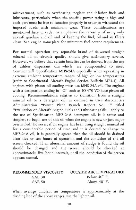
mistreatment, such as overheating; neglect and inferior fuels and lubricants, particularly when the specific power rating is high and each part must be free to function properly in order to withstand the imposed loads with minimum wear. These considerations are mentioned here in order to emphasize the necessity of using only aircraft gasoline and oil and of keeping the fuel, oil and air filters clean. See engine nameplate for minimum fuel octane requirement.
For normal operation any reputable brand of de-waxed straight mineral oil of aircraft quality should give satisfactory service. However, we believe that certain benefits can be derived from the use of ashless dispersant oils which are compounded to meet Continental® Specification MHS-24A especially when operating in extreme ambient temperature ranges of high or low temperatures (refer to Continental Aircraft Engine Service Bulletin M73-3). All engines with piston oil cooling must use MHS-24A oil. The engines with a designation ending in "0" such as IO-470-VO have piston oil cooling. Recommendations relative to transition from a straight mineral oil to a detergent oil, as outlined in civil Aeronautics Administration "Power plant Branch Report No. I" titled "Evaluation of Aircraft Engine Fuels and Lubricating Oils," apply to the use of Specification MHS-24A detergent oil. It is safest and simplest to begin use of this oil when the engine is new or just major overhauled. However, if an engine has been using straight mineral oil for a considerable period of time and it is desired to change to MHS-24A oil, it is generally agreed that the oil should be drained after five or ten hours of operation and the condition of the oil screen checked. If an abnormal amount of sludge is found the oil should be changed and the screen should be checked at approximately five hour intervals, until the condition of the screen appears normal.
RECOMMENDED VISCOSITY SAE 30 SAE 50
OUTSIDE AIR TEMPERATURE Below 40° F. Above 40° F.
When average ambient air temperature is approximately at the dividing line of the above ranges, use the lighter oil.
10
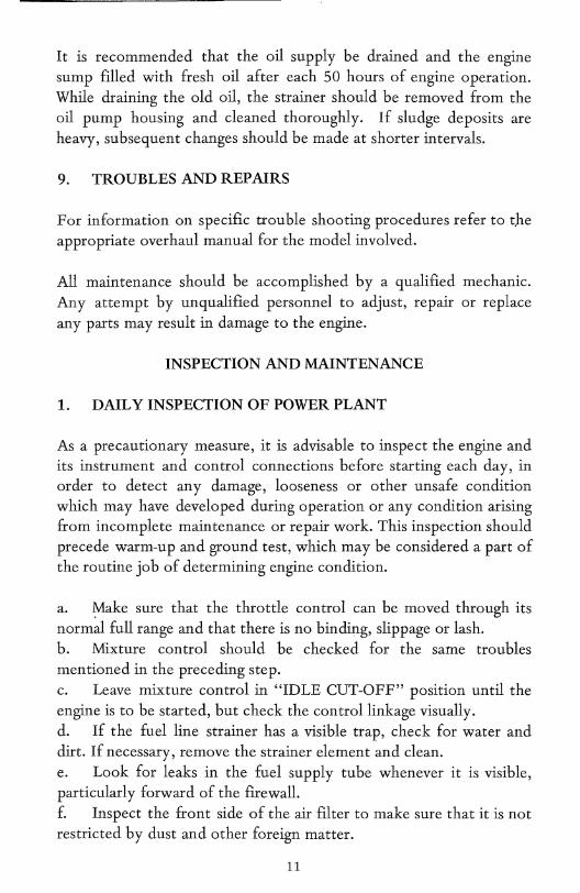
It is recommended that the oil supply be drained and the engine sump filled with fresh oil after each 50 hours of engine operation. While draining the old oil, the strainer should be removed from the oil pump housing and cleaned thoroughly. If sludge deposits are heavy, subsequent changes should be made at shorter intervals.
9. TROUBLES AND REPAIRS
For information on specific trouble shooting procedures refer to t.he appropriate overhaul manual for the model involved.
All maintenance should be accomplished by a qualified mechanic. Any attempt by unqualified personnel to adjust, repair or replace any parts may result in damage to the engine.
INSPECTION AND MAINTENANCE
1. DAIL Y INSPECTION OF POWER PLANT
As a precautionary measure, it is advisable to inspect the engine and its instrument and control connections before starting each day, in order to detect any damage, looseness or other unsafe condition which may have developed during operation or any condition arising from incomplete maintenance or repair work. This inspection should precede warm-up and ground test, which may be considered a part of the routine job of determining engine condition.
a. ~ake sure that the throttle control can be moved through its normal full range and that there is no binding, slippage or lash. b. . Mixture control should be checked for the same troubles mentioned in the preceding step. c. Leave mixture control in "IDLE CUT-OFF" position until the engine is to be started, but check the control linkage visually. d. If the fuel line strainer has a visible trap, check for water and dirt. If necessary, remove the strainer element and clean. e. Look for leaks in the fuel supply tube whenever it is visible, particularly forward of the firewalL f. Inspect the front side of the air filter to make sure that it is not restricted by dust and other foreign matter.
11
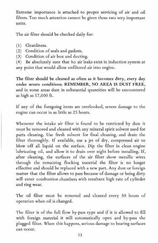
Extreme importance is attached to proper servicing of air and oil filters. Too much attention cannot be given these two very important units.
The air filter should be checked daily for:
(1) Cleanliness. (2) Condition of seals and gaskets. (3) Condition of air box and ducting. ( 4) Be absolutely sure that no air leaks exist in induction system at any point that would allow unfiltered air into engine.
The filter should be cleaned as often as it becomes dirty, every day under severe conditions. REMEMBER, NO AREA IS DUST FREE, and in some areas dust in substantial quantities will be encountered as high as 17,000 ft.
If any of the foregoing items are overlooked, severe damage to the engine can occur in as little as 25 hours. .
Whenever the intake air filter is found to be restricted by dust it must be removed and cleaned with any mineral spirit solvent used for parts cleaning. Use fresh solvent for final cleaning, and drain the filter thoroughly. If available, use a jet of dry, compressed air to blow off all liquid on the surface. Dip the filter in clean engine lubricating oil, and allow it to drain over night before installing. If, after cleaning, the surfaces of the air filter show metallic wires through the remaining flocking material the filter is no longer effective and should be replaced with a new part. Any dust or foreign matter that the filter allows to pass because of damage or being dirty will enter combustion chambers with resultant high rate of cylinder and ring wear.
The oil filter must be removed and cleaned every 50 hours of operation when oil is changed.
The filter is of the full flow by-pass type and if it is allowed to fill with foreign material it will automatically open and by-pass the plugged filter. When this happens, serious damage to bearing surfaces can occur.
12
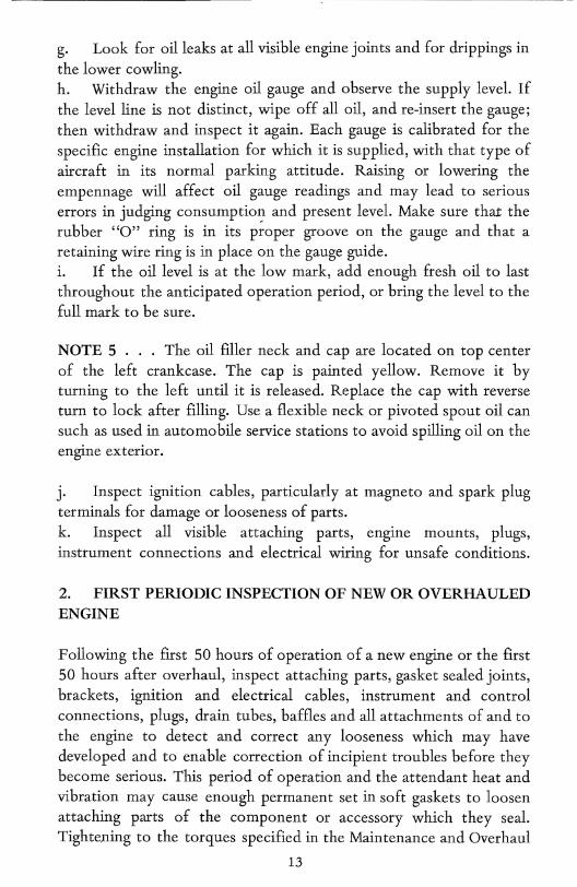
g. Look for oil leaks at all visible engine joints and for drippings in
the lower cowling. h. Withdraw the engine oil gauge and observe the supply level. If the level line is not distinct, wipe off all oil, and re-insert the gauge; then withdraw and inspect it again. Each gauge is calibrated for the specific engine installation for which it is supplied, with that type of aircraft in its normal parking attitude. Raising or lowering the empennage will affect oil gauge readings and may lead to serious errors in judging consumption and present level. Make sure that the rubber "0" ring is in its p~oper groove on the gauge and that a retaining wire ring is in place on the gauge guide. i. If the oil level is at the low mark, add enough fresh oil to last throughout the anticipated operation period, or bring the level to the full mark to be sure.
NOTE 5 . . . The oil fIller neck and cap are located on top center of the left crankcase. The cap is painted yellow. Remove it by turning to the left until it is released. Replace the cap with reverse turn to lock after filling. Use a flexible neck or pivoted spout oil can such as used in automobile service stations to avoid spilling oil on the engine exterior.
j. Inspect ignition cables, particularly at magneto and spark plug terminals for damage or looseness of parts. k. Inspect all visible attaching parts, engine mounts, plugs, instrument connections and electrical wiring for unsafe conditions.
2. FIRST PERIODIC INSPECTION OF NEW OR OVERHAULED ENGINE
Following the first 50 hours of operation of a new engine or the first 50 hours after overhaul, inspect attaching parts, gasket sealed joints, brackets, ignition and electrical cables, instrument and control connections, plugs, drain tubes, baffles and all attachments of and to the engine to detect and correct any looseness which may have developed and to enable correction of incipient troubles before they become serious. This period of operation and the attendant heat and vibration may cause enough permanent set in soft gaskets to loosen attaching parts of the component or accessory which they seal. Tightening to the torques specified in the Maintenance and Overhaul
13
-_. -~------. _. -.--~-~---
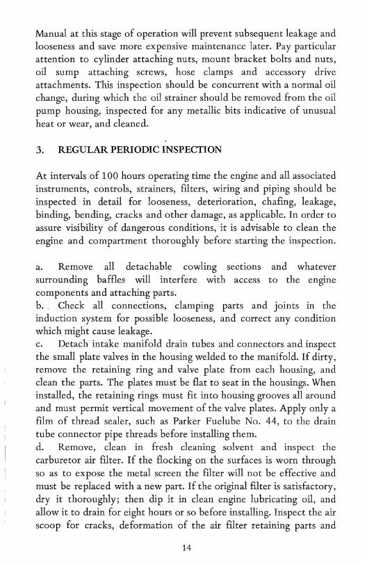
Manual at this stage of operation will prevent subsequent leakage and looseness and save more expensive maintenance later. Pay particular attention to cylinder attaching nuts, mount bracket bolts and nuts, oil sump attaching screws, hose clamps and accessory drive attachments. This inspection should be concurrent with a normal oil change, during which the oil strainer should be removed from the oil pump housing, inspected for any metallic bits indicative of unusual heat or wear, and cleaned.
3. REGULAR PERIODIC INSPECTION
At intervals of 100 hours operating time the engine and all associated instruments, controls, strainers, filters, wiring and piping should be inspected in detail for looseness, deterioration, chafing, leakage, binding, bending, cracks and other damage, as applicable. In order to assure visibility of dangerous conditions, it is advisable to clean the engine and compartment thoroughly before starting the inspection.
a. Remove all detachable cowling sections surrounding baffles will interfere with access
and whatever to the engine
components and attaching parts. b., Check all connections, clamping induction system for possible looseness, which might cause leakage.
parts and joints in the and correct any condition
c. Detach intake manifold drain tubes and connectors and inspect the small plate valves in the housing welded to the manifold. If dirty, remove the retaining ring and valve plate from each housing, and clean the parts. The plates must be flat to seat in the housings. When installed, the retaining rings must fit into housing grooves all around and must permit vertical movement of the valve plates. Apply only a film of thread sealer, such as Parker Fuelube No. 44, to the drain tube connector pipe threads before installing them. d. Remove, clean in fresh cleaning solvent and inspect the carburetor air filter. If the flocking on the surfaces is worn through so as to expose the metal screen the filter will not be effective and must be replaced with a new part. If the original filter is satisfactory, dry it thoroughly; then dip it in clean engine lubricating oil, and allow it to drain for eight hours or so before installing. Inspect the air scoop for cracks, deformation of the air filter retaining parts and
14
l 'I !
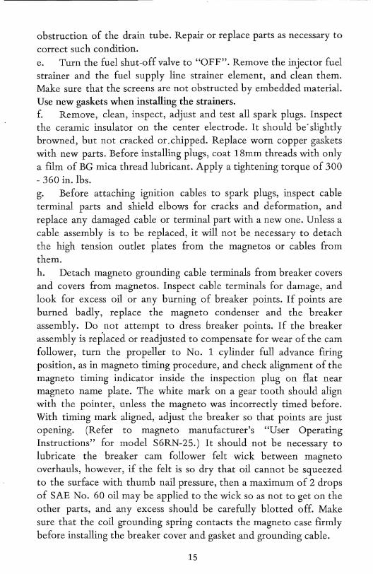
obstruction of the drain tube. Repair or replace parts as necessary to correct such condition. e. Turn the fuel shut-off valve to "OFF". Remove the injector fuel strainer and the fuel supply line strainer element, and clean them. Make sure that the screens are not obstructed by embedded material. Use new gaskets when installing the strainers. f. Remove, clean, inspect, adjust and test all spark plugs. Inspect the ceramic insulator on the center electrode. It should be'slightly browned, but not cracked or ,chipped. Replace worn copper gaskets with new parts, Before installing plugs, coat 18mm threads with only a ftlm of BG mica thread lubricant. Apply a tightening torque of 300 - 360 in. lbs. g. Before attaching ignition cables to spark plugs, inspect cable terminal parts and shield elbows for cracks and deformation, and replace any damaged cable or terminal part with a new one. Unless a cable assembly is to be replaced, it will not be necessary to detach the high tension outlet plates from the magnetos or cables from them. h. Detach magneto grounding cable terminals from breaker covers and covers from magnetos. Inspect cable terminals for damage, and look for excess oil or any burning of breaker points. If points are burned badly, replace the magneto condenser and the breaker assembly. Do not attempt to dress breaker points. If the breaker assembly is replaced or readjusted to compensate for wear of the cam follower, turn the propeller to No. 1 cylinder full advance fIring position, as in magneto timing procedure, and check alignment of the magneto timing indicator inside the inspection plug on flat near magneto name plate. The white mark on a gear tooth should align with the pointer, unless the magneto was incorrectly timed before. With timing mark aligned, adjust the breaker so that points are just opening. (Refer to magneto manufacturer's "User Operating Instructions" for model S6RN-25.) It should not be necessary to lubricate the breaker cam follower felt wick between magneto overhauls, however, if the felt is so dry that oil cannot be squeezed to the surface with thumb nail pressure, then a maximum of 2 drops of SAE No. 60 oil may be applied to the wick so as not to get on the other parts, and any excess should be carefully blotted off. Make sure that the coil grounding spring· contacts the magneto case frrmly before installing the breaker cover and gasket and grounding cable.
15
i. Remove valve rocker covers, and inspect visible parts of the valve mechanism for breakage and lack of lubrication. All parts should be covered with oil. If any rocker box is dry, or if the lower end of any valve rocker can be depressed by hand so as to allow a lash in the train, then the valve lifters under that cylinder should be removed, cleaned and inspected. Any valve lifter which cannot be made to operate properly by cleaning must be replaced with a new assembly. Make sure that pushrod oil holes are clear if the pushrods are removed on account of. lubrication failure. If oil leakage was found at the pushrod housing ends replace the housing oil seals with new parts. Use new gaskets to seal the covers, and install new lockwashers under attaching screw heads. j. Inspect the exhaust system for looseness of joints and other damage. If loose at any cylinder head, replace the copper-asbestos gasket in that joint. k. Test the generator drive belt tension by moving either side up and down. A movement of 1/2 inch either side of normal position indicates correct tension. If too loose, tighten the belt by shifting the generator outward on its pivot.
It is recommended that when any engine requires repair or major overhaul that the overhaul manuals covering the specific model be used as a reference for fits, limits and methods.
l. Differential Pressure Compression Check: The differential pressure tester is designed to check the compression of aircraft engines by measuring the leakage through the cylinders caused by worn or damaged components. The operation of the compression tester is based on the principle that, for any given airflow through a fixed orifice, a constant pressure drop across that orifice will result.
The restrict or orifice dimensions for Continental aircraft engines should be 0.040 inch orifice diameter, 0.250 inch long with 60° approach angle.
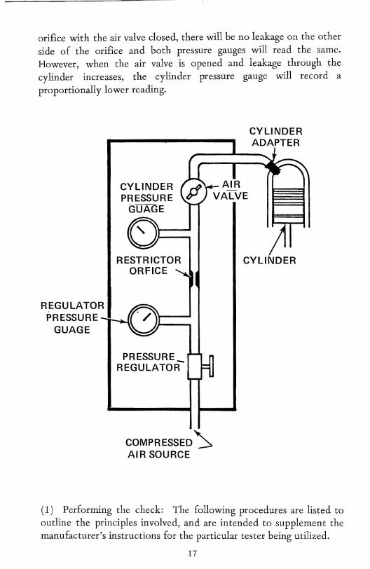
A typical schematic diagram of a differential pressure tester is shown below.
As the regulated air pressure is applied to one side of the restrict or
16
"--~--------1
orifice with the air valve closed, there will be no leakage on the other side of the orifice and both pressure gauges will read the same. However, when the air valve is opened and leakage through the cylinder increases, the cylinder pressure gauge will record a proportionally lower reading.
REGULATOR PRESSURE
GUAGE
CYLINDER PRESSURE
GUAGE
RESTRICTOR ORFICE
PRESSURE_ REGULATOR
COMPRESSED ~ AIR SOURCE
CYLINDER ADAPTER
CYLINDER
(1) Performing the check: The following procedures are listed to outline the principles involved, and are intended to supplement the manufacturer's instructions for the particular tester being utilized.
17
(a) Perform the compression test as soon as possible after the engine is shut down to ensure that the piston rings, cylinder walls, and other engine parts are well lubricated. (b) Remove the most accessible spark plug from each cylinder. (c) With the air valve closed, apply an external source of clean air (approximately 100 to 120 p.s.i.) to the tester. (d) Install an adapter in the spark plug bushing and connect the compression tester to the cylinder. (e) Adjust the pressure regulator to obtain a reading of 80 p.s.i. on the regulator pressure gauge. At this time, the cylinder pressure gauge should also register 80 p.s.i. (f) Turn the crankshaft by hand in the direction of rotation until the piston (in the cylinder being checked) is coming up on its compression stroke. Slowly open the air valve and pressurize the cylinder to approximately 20 p.s.i.
CA UTION . . . Care must be exercised in opening the air valve since sufficient air pressure will be built up in the cylinder to cause it to rotate the crankshaft if the piston is not at TDG.
Continue rotating the engine against this pressure until the piston reaches top dead center (TDC). Reaching TDG is indicated by a flat spot or sudden decrease in force required to turn the crankshaft. If the crankshaft is rotated too far, back up at least one-halfrevolution and start over again to eliminate the effect of backlash in the valve operating mechanism and to keep piston rings seated on the lower ring lands.
(g) Open the air valve completely. Check the regulated pressure and adjust, if necessary, to 80 p.s.i. .. . ..
(h) Observe the pressure indication on the cylinder pressure gauge. The difference between this pressure and the pressure shown by the regulator pressure gauge is the amount of leakage through the cylinder. A loss in excess of 25 percent of the input air pressure is cause to suspect the cylinder of being defective; however, recheck the readings after operating the engine for at least 3 minutes to- allow for sealing of the rings with oil. . (i) The source of air leakage can be determined by listening for the sound of flowing air at the intake, exhaust and crankcase vent.
18
(1) Leakage at exhaust signifies bad exhaust valve or foreign material under the valve face. (2) Leakage at intake signifies bad intake valve or foreign material under the valve face. (3) Leakage at the crankcase vent signifies broken, stuck or worn piston rings.
(j) If leakage is still occurring after a recheck, it may be possible to correct a low reading by staking the valves. This is accomplished by placing a fiber drift on the rocker arm directly over the valve stem and tapping the drift several times with a hammer to dislodge any foreign material between the valve face and seat.
NOTE ... When correcting a low reading in this manner, rotate the propeller so the piston will not be at TDC. This is necessary to prevent the valve from striking the top of the piston in some engines. Rotate the engine before rechecking compression to reseat the valves in the normal manner.
INJECTION SERVICE AND MAINTENANCE
When service is required, it is definitely worth checking other engine systems (particularly the aircraft fuel system and the ignition system) to be sure that the systems are functioning correctly before concluding that the trouble lies in the fuel injection system. Any fuel injection system trouble most likely will be associated with dirt or foreign matter in the system. The condition of the filter screens at the fuel injection control valve, at the fuel manifold valve, the nozzle air screens, and the main fuel filter in the aircraft supply line will go far in determining the cause of any trouble. Keep these filter units clean and the likelihood of trouble in the fuel injection system is rare.
1. ADJUSTMENTS
The idle speed adjustment is a conventional spring-loaded screw located in the air throttle lever. Set for idling speed as specified in aircraft handbook.
19
The idle mixture adjustment is the locknut at the metering valve end of the linkage between the metering valve and air throttle levers. Tightening the nut to shorten the linkage provides a richer mixture. A leaner mixture is obtained by backing off the nut to lengthen the linkage. Adjust to obtain a slight and momentary gain in idle speed as the mixture control is slowly moved toward idle cut off. (If set too lean, idle speed will drop under the same conditions.)
The injection pump pressure, is part of the basic calibration and requires the services of an authorized representative with the necessary equipment for testing and/or resetting. Do not attempt any adjustment other than idle speed and idle mixture as described. See Service Bulletin No. 72-3.
2. PERIODIC INSPECTION
While the basically simple design requires very little maintenance between overhauls, the following points are worth checking at normal periodic engine inspections:
a. Check all attaching parts for tightness. Check safetying devices. b. Check all fuel lines for leaks, evidence of damage such as sharp bends for flattened tubes, or chafing by metal-to-metal contact. c. Check control connections, levers, and linkages for security of attaching parts, for safetying, and for lost motion due to wear. d. Inspect nozzles for cleanliness, with particular attention to air screens and orifices. (Use standard 1/2 inch spark plug type deep socket to remove nozzles.) Do not remove shield to clean air screens in nozzles. Do not use wire or other object to clean orifices. To clean nozzles, remove from engine and immerse in tresh cleaning solvent. Use compressed air to dry. e. Unscrew strainer plug trom fuel injection control valve and clean screen in tresh cleaning solvent. Reinstall, safety, and check for leaks. f. In periodic lubrication, add a drop of engine grade oil on each end of the air throttle shaft and at each end of the linkage between the air throttle and fuel metering valve. No other lubrication is required. g. In the event that a line fitting in any part of the .injection system must be replaced, only a fuel soluble lubricant (stich as engine
20
oil) is authorized on the fitting threads at installation. Do not use any other form of thread compound.
Unless damaged, there should be little reason to replace nozzles. However, it is not necessary to replace nozzles as a set, but each
I replacement nozzle must match the one removed as marked.
~ ' .
. '.
21
I