Embed Size (px)
DESCRIPTION
PAK MASTER 100XL Plasma Cutter manual
Citation preview

Manual No. 0-2611December 16, 1998
PAK MASTER ® 100XLAir Plasma Cutting
Power Supply (CE)
Operating Manual
A-01355

WARNING
WARNING
Read and understand this entire Operating Manual and youremployer’s safety practices before installing, operating, orservicing the equipment.
While the information contained in this Operating Manualrepresents our best judgement, Thermal Dynamics Corporationassumes no liability for its use.
Pak Master® 100XL Air Plasma Cutting Power Supply (CE)Operating Manual Number 0-2611
Published by:Thermal Dynamics CorporationIndustrial Park No. 2West Lebanon, New Hampshire, USA 03784(603) 298-5711
Copyright 1997 byThermal Dynamics Corporation
All rights reserved.
Reproduction of this work, in whole or in part, without writtenpermission of the publisher is prohibited.
The publisher does not assume and hereby disclaims any liabil-ity to any party for any loss or damage caused by any error oromission in the Pak Master® 100XL Air Plasma Cutting PowerSupply (CE)Operating Manual, whether such error results fromnegligence, accident, or any other cause.
Printed in the United States of America
December 16, 1998
TABLE OF CONTENTS
SECTION 1:GENERAL INFORMATION .................................................................................................. 1
1.01 Notes, Cautions and Warnings ...................................................................... 11.02 Important Safety Precautions ........................................................................ 11.03 Publications ................................................................................................... 21.04 Note, Attention et Avertissement ................................................................... 31.05 Precautions De Securite Importantes ........................................................... 31.06 Documents De Reference ............................................................................. 51.07 Declaration of Conformity .............................................................................. 61.08 Statement of Warranty .................................................................................. 7
SECTION 2:INTRODUCTION ................................................................................................................. 9
2.01 Scope of Manual ........................................................................................... 92.02 General Description ...................................................................................... 92.03 Specifications/Design Features ..................................................................... 92.04 Power Supply Options and Accessories ...................................................... 10
SECTION 3:INSTALLATION PROCEDURES ........................................................................................ 11
3.01 Introduction ................................................................................................. 113.02 Site Selection .............................................................................................. 113.03 Unpacking ................................................................................................... 113.04 Lifting Options ............................................................................................. 123.05 Input Power Connections ............................................................................ 123.06 Input Voltage Selection ................................................................................ 133.07 Input Power Cable Connections .................................................................. 133.08 Gas Connections ......................................................................................... 143.09 Connecting Torch Leads .............................................................................. 153.10 Work Cable And Ground Connections......................................................... 16
SECTION 4:OPERATION ...................................................................................................................... 19
4.01 Introduction ................................................................................................. 194.02 Functional Overview .................................................................................... 194.03 Operating Controls ...................................................................................... 194.04 Sequence Of Operation .............................................................................. 214.05 Preparations for Operating .......................................................................... 224.06 Cut Quality .................................................................................................. 22
SECTION 5:CUSTOMER/OPERATOR SERVICE ................................................................................. 25
5.01 Introduction ................................................................................................. 255.02 General Maintenance .................................................................................. 255.03 Common Operating Problems ..................................................................... 255.04 Troubleshooting Guide ................................................................................. 265.05 Power Supply Parts Replacement ............................................................... 28

TABLE OF CONTENTS (continued)
SECTION 6:PARTS LISTS .................................................................................................................... 31
6.01 Introduction ................................................................................................. 316.02 Ordering Information ................................................................................... 316.03 Complete Power Supply Replacement ........................................................ 326.04 Options and Accessories ............................................................................ 32
APPENDIX I: INPUT WIRING REQUIREMENTS ..................................................................... 33
APPENDIX II: SEQUENCE OF OPERATION (BLOCK DIAGRAM) .......................................... 34
APPENDIX III: SYSTEM SCHEMATIC ..................................................................................... 36

1 GENERAL INFORMATION
SECTION 1:GENERAL INFORMATION
1.01 Notes, Cautions and Warnings
Throughout this manual, notes, cautions, and warningsare used to highlight important information. These high-lights are categorized as follows:
NOTE
An operation, procedure, or background informa-tion which requires additional emphasis or is help-ful in efficient operation of the system.
CAUTION
A procedure which, if not properly followed, maycause damage to the equipment.
WARNING
A procedure which, if not properly followed, maycause injury to the operator or others in the oper-ating area.
1.02 Important Safety Precautions
WARNING
OPERATION AND MAINTENANCE OFPLASMA ARC EQUIPMENT CAN BE DAN-GEROUS AND HAZARDOUS TO YOURHEALTH.
To prevent possible injury, read, understand andfollow all warnings, safety precautions and in-structions before using the equipment. Call 1-603-298-5711 or your local distributor if you have anyquestions.
GASES AND FUMES
Gases and fumes produced during the plasma cuttingprocess can be dangerous and hazardous to your health.
• Keep all fumes and gases from the breathing area.Keep your head out of the welding fume plume.
• Use an air-supplied respirator if ventilation is notadequate to remove all fumes and gases.
• The kinds of fumes and gases from the plasma arcdepend on the kind of metal being used, coatingson the metal, and the different processes. You mustbe very careful when cutting or welding any met-als which may contain one or more of the follow-ing:
Antimony Chromium MercuryArsenic Cobalt NickelBarium Copper SeleniumBeryllium Lead SilverCadmium Manganese Vanadium
• Always read the Material Safety Data Sheets (MSDS)that should be supplied with the material you areusing. These MSDSs will give you the informationregarding the kind and amount of fumes and gasesthat may be dangerous to your health.
• For information on how to test for fumes and gasesin your workplace, refer to item 1 in Subsection1.03, Publications in this manual.
• Use special equipment, such as water or down draftcutting tables, to capture fumes and gases.
• Do not use the plasma torch in an area where com-bustible or explosive gases or materials are located.
• Phosgene, a toxic gas, is generated from the vaporsof chlorinated solvents and cleansers. Remove allsources of these vapors.
ELECTRIC SHOCK
Electric Shock can injure or kill. The plasma arc processuses and produces high voltage electrical energy. Thiselectric energy can cause severe or fatal shock to the op-erator or others in the workplace.
• Never touch any parts that are electrically “live” or“hot.”
• Wear dry gloves and clothing. Insulate yourself fromthe work piece or other parts of the welding cir-cuit.
• Repair or replace all worn or damaged parts.
• Extra care must be taken when the workplace ismoist or damp.
• Install and maintain equipment according to NECcode, refer to item 9 in Subsection 1.03, Publica-tions.
• Disconnect power source before performing any ser-vice or repairs.
• Read and follow all the instructions in the Operat-ing Manual.
GENERAL INFORMATION 2
FIRE AND EXPLOSION
Fire and explosion can be caused by hot slag, sparks, orthe plasma arc.
• Be sure there is no combustible or flammable mate-rial in the workplace. Any material that cannot beremoved must be protected.
• Ventilate all flammable or explosive vapors fromthe workplace.
• Do not cut or weld on containers that may have heldcombustibles.
• Provide a fire watch when working in an area wherefire hazards may exist.
• Hydrogen gas may be formed and trapped underaluminum workpieces when they are cut under-water or while using a water table. DO NOT cutaluminum alloys underwater or on a water tableunless the hydrogen gas can be eliminated or dis-sipated. Trapped hydrogen gas that is ignited willcause an explosion.
NOISE
Noise can cause permanent hearing loss. Plasma arc pro-cesses can cause noise levels to exceed safe limits. Youmust protect your ears from loud noise to prevent per-manent loss of hearing.
• To protect your hearing from loud noise, wear pro-tective ear plugs and/or ear muffs. Protect othersin the workplace.
• Noise levels should be measured to be sure the deci-bels (sound) do not exceed safe levels.
• For information on how to test for noise, see item 1in Subsection 1.03, Publications, in this manual.
PLASMA ARC RAYS
Plasma Arc Rays can injure your eyes and burn your skin.The plasma arc process produces very bright ultra violetand infra red light. These arc rays will damage youreyes and burn your skin if you are not properly protected.
• To protect your eyes, always wear a welding hel-met or shield. Also always wear safety glasses withside shields, goggles or other protective eye wear.
• Wear welding gloves and suitable clothing to pro-tect your skin from the arc rays and sparks.
• Keep helmet and safety glasses in good condition.Replace lenses when cracked, chipped or dirty.
• Protect others in the work area from the arc rays.Use protective booths, screens or shields.
• Use the shade of lens as recommended in Subsec-tion 1.03, item 4.
1.03 Publications
Refer to the following standards or their latest revisionsfor more information:
1. OSHA, SAFETY AND HEALTH STANDARDS,29CFR 1910, obtainable from the Superintendent ofDocuments, U.S. Government Printing Office, Wash-ington, D.C. 20402
2. ANSI Standard Z49.1, SAFETY IN WELDING ANDCUTTING, obtainable from the American WeldingSociety, 550 N.W. LeJeune Rd, Miami, FL 33126
3. NIOSH, SAFETY AND HEALTH IN ARC WELD-ING AND GAS WELDING AND CUTTING, obtain-able from the Superintendent of Documents, U.S.Government Printing Office, Washington, D.C. 20402
4. ANSI Standard Z87.1, SAFE PRACTICES FOR OC-CUPATION AND EDUCATIONAL EYE AND FACEPROTECTION, obtainable from American NationalStandards Institute, 1430 Broadway, New York, NY10018
5. ANSI Standard Z41.1, STANDARD FOR MEN’SSAFETY-TOE FOOTWEAR, obtainable from theAmerican National Standards Institute, 1430 Broad-way, New York, NY 10018
6. ANSI Standard Z49.2, FIRE PREVENTION IN THEUSE OF CUTTING AND WELDING PROCESSES,obtainable from American National Standards Insti-tute, 1430 Broadway, New York, NY 10018
7. AWS Standard A6.0, WELDING AND CUTTINGCONTAINERS WHICH HAVE HELD COMBUS-TIBLES, obtainable from American Welding Society,550 N.W. LeJeune Rd, Miami, FL 33126
8. NFPA Standard 51, OXYGEN-FUEL GAS SYSTEMSFOR WELDING, CUTTING AND ALLIED PRO-CESSES, obtainable from the National Fire Protec-tion Association, Batterymarch Park, Quincy, MA02269
9. NFPA Standard 70, NATIONAL ELECTRICALCODE, obtainable from the National Fire ProtectionAssociation, Batterymarch Park, Quincy, MA 02269
10. NFPA Standard 51B, CUTTING AND WELDINGPROCESSES, obtainable from the National Fire Pro-tection Association, Batterymarch Park, Quincy, MA02269
11. CGA Pamphlet P-1, SAFE HANDLING OF COM-PRESSED GASES IN CYLINDERS, obtainable fromthe Compressed Gas Association, 1235 JeffersonDavis Highway, Suite 501, Arlington, VA 22202
3 GENERAL INFORMATION
12. CSA Standard W117.2, CODE FOR SAFETY INWELDING AND CUTTING, obtainable from the Ca-nadian Standards Association, Standards Sales, 178Rexdale Boulevard, Rexdale, Ontario, Canada M9W1R3
13. NWSA booklet, WELDING SAFETY BIBLIOGRA-PHY obtainable from the National Welding SupplyAssociation, 1900 Arch Street, Philadelphia, PA 19103
14. American Welding Society Standard AWSF4.1, REC-OMMENDED SAFE PRACTICES FOR THE PREPA-RATION FOR WELDING AND CUTTING OF CON-TAINERS AND PIPING THAT HAVE HELDHAZARDOUS SUBSTANCES, obtainable from theAmerican Welding Society, 550 N.W. LeJeune Rd,Miami, FL 33126
15. ANSI Standard Z88.2, PRACTICE FOR RESPIRA-TORY PROTECTION, obtainable from AmericanNational Standards Institute, 1430 Broadway, NewYork, NY 10018
1.04 Note, Attention etAvertissement
Dans ce manuel, les mots “note,” “attention,” et“avertissement” sont utilisés pour mettre en relief desinformations à caractère important. Ces mises en reliefsont classifiées comme suit :
NOTE
Toute opération, procédure ou renseignementgénéral sur lequel il importe d’insister davantageou qui contribue à l’efficacité de fonctionnementdu système.
ATTENTION
Toute procédure pouvant résulterl’endommagement du matériel en cas de non-respect de la procédure en question.
AVERTISSEMENT
Toute procédure pouvant provoquer des blessuresde l’opérateur ou des autres personnes se trouvantdans la zone de travail en cas de non-respect de laprocédure en question.
1.05 Precautions De SecuriteImportantes
AVERTISSEMENT
L’OPÉRATION ET LA MAINTENANCE DUMATÉRIEL DE SOUDAGE À L’ARC AU JETDE PLASMA PEUVENT PRÉSENTER DESRISQUES ET DES DANGERS DE SANTÉ.
Il faut communiquer aux opérateurs et au person-nel TOUS les dangers possibles. Afin d’éviter lesblessures possibles, lisez, comprenez et suivez tousles avertissements, toutes les précautions desécurité et toutes les consignes avant d’utiliser lematériel. Composez le + 603-298-5711 ou votredistributeur local si vous avez des questions.
FUMÉE et GAZ
La fumée et les gaz produits par le procédé de jet deplasma peuvent présenter des risques et des dangers desanté.
• Eloignez toute fumée et gaz de votre zone de respi-ration. Gardez votre tête hors de la plume de fuméeprovenant du chalumeau.
• Utilisez un appareil respiratoire à alimentation enair si l’aération fournie ne permet pas d’éliminer lafumée et les gaz.
• Les sortes de gaz et de fumée provenant de l’arc deplasma dépendent du genre de métal utilisé, desrevêtements se trouvant sur le métal et des différentsprocédés. Vous devez prendre soin lorsque vouscoupez ou soudez tout métal pouvant contenir unou plusieurs des éléments suivants:
antimoine cadmium mercureargent chrome nickelarsenic cobalt plombbaryum cuivre séléniumbéryllium manganèse vanadium
• Lisez toujours les fiches de données sur la sécuritédes matières (sigle américain “MSDS”); celles-cidevraient être fournies avec le matériel que vousutilisez. Les MSDS contiennent des renseignementsquant à la quantité et la nature de la fumée et desgaz pouvant poser des dangers de santé.
• Pour des informations sur la manière de tester lafumée et les gaz de votre lieu de travail, consultezl’article 1 et les documents cités à la page 5.
GENERAL INFORMATION 4
• Utilisez un équipement spécial tel que des tables decoupe à débit d’eau ou à courant descendant pourcapter la fumée et les gaz.
• N’utilisez pas le chalumeau au jet de plasma dansune zone où se trouvent des matières ou des gazcombustibles ou explosifs.
• Le phosgène, un gaz toxique, est généré par la fuméeprovenant des solvants et des produits de nettoyagechlorés. Eliminez toute source de telle fumée.
CHOC ELECTRIQUE
Les chocs électriques peuvent blesser ou même tuer. Leprocédé au jet de plasma requiert et produit de l’énergieélectrique haute tension. Cette énergie électrique peutproduire des chocs graves, voire mortels, pour l’opérateuret les autres personnes sur le lieu de travail.
• Ne touchez jamais une pièce “sous tension” ou“vive”; portez des gants et des vêtements secs.Isolez-vous de la pièce de travail ou des autres par-ties du circuit de soudage.
• Réparez ou remplacez toute pièce usée ouendommagée.
• Prenez des soins particuliers lorsque la zone de tra-vail est humide ou moite.
• Montez et maintenez le matériel conformément auCode électrique national des Etats-Unis. (Voir lapage 5, article 9.)
• Débranchez l’alimentation électrique avant tout tra-vail d’entretien ou de réparation.
• Lisez et respectez toutes les consignes du Manuelde consignes.
INCENDIE ET EXPLOSION
Les incendies et les explosions peuvent résulter des scorieschaudes, des étincelles ou de l’arc de plasma. Le procédéà l’arc de plasma produit du métal, des étincelles, desscories chaudes pouvant mettre le feu aux matières com-bustibles ou provoquer l’explosion de fuméesinflammables.
• Soyez certain qu’aucune matière combustible ou in-flammable ne se trouve sur le lieu de travail.Protégez toute telle matière qu’il est impossible deretirer de la zone de travail.
• Procurez une bonne aération de toutes les fuméesinflammables ou explosives.
• Ne coupez pas et ne soudez pas les conteneurs ayantpu renfermer des matières combustibles.
• Prévoyez une veille d’incendie lors de tout travaildans une zone présentant des dangers d’incendie.
• Le gas hydrogène peut se former ou s’accumulersous les pièces de travail en aluminium lorsqu’ellessont coupées sous l’eau ou sur une table d’eau. NEPAS couper les alliages en aluminium sous l’eau ousur une table d’eau à moins que le gas hydrogènepeut s’échapper ou se dissiper. Le gas hydrogèneaccumulé explosera si enflammé.
RAYONS D’ARC DE PLASMA
Les rayons provenant de l’arc de plasma peuvent blesservos yeux et brûler votre peau. Le procédé à l’arc de plasmaproduit une lumière infra-rouge et des rayons ultra-vio-lets très forts. Ces rayons d’arc nuiront à vos yeux etbrûleront votre peau si vous ne vous protégez pascorrectement.
• Pour protéger vos yeux, portez toujours un casqueou un écran de soudeur. Portez toujours des lunettesde sécurité munies de parois latérales ou des lu-nettes de protection ou une autre sorte de protec-tion oculaire.
• Portez des gants de soudeur et un vêtementprotecteur approprié pour protéger votre peaucontre les étincelles et les rayons de l’arc.
• Maintenez votre casque et vos lunettes de protec-tion en bon état. Remplacez toute lentille sale oucomportant fissure ou rognure.
• Protégez les autres personnes se trouvant sur la zonede travail contre les rayons de l’arc en fournissantdes cabines ou des écrans de protection.
• Respectez le teint de lentille recommandé dans learticle 4, page 5.
BRUIT
Le bruit peut provoquer une perte permanente de l’ouïe.Les procédés de soudage à l’arc de plasma peuventprovoquer des niveaux sonores supérieurs aux limitesnormalement acceptables. Vous dú4ez vous protéger lesoreilles contre les bruits forts afin d’éviter une pertepermanente de l’ouïe.
• Pour protéger votre ouïe contre les bruits forts, portezdes tampons protecteurs et/ou des protectionsauriculaires. Protégez également les autrespersonnes se trouvant sur le lieu de travail.
• Il faut mesurer les niveaux sonores afin d’assurerque les décibels (le bruit) ne dépassent pas lesniveaux sûrs.
5 GENERAL INFORMATION
• Pour des renseignements sur la manière de tester lebruit, consultez l’article 1, page 5.
1.06 Documents De Reference
Consultez les normes suivantes ou les révisions les plusrécentes ayant été faites à celles-ci pour de plus amplesrenseignements :
1. OSHA, NORMES DE SÉCURITÉ DU TRAVAIL ETDE PROTECTION DE LA SANTÉ, 29CFR 1910,disponible auprès du Superintendent of Docu-ments, U.S. Government Printing Office, Washing-ton, D.C. 20402
2. Norme ANSI Z49.1, LA SÉCURITÉ DESOPÉRATIONS DE COUPE ET DE SOUDAGE,disponible auprès de la Société Américaine deSoudage (American Welding Society), 550 N.W.LeJeune Rd., Miami, FL 33126
3. NIOSH, LA SÉCURITÉ ET LA SANTÉ LORS DESOPÉRATIONS DE COUPE ET DE SOUDAGE ÀL’ARC ET AU GAZ, disponible auprès du Superin-tendent of Documents, U.S. Government PrintingOffice, Washington, D.C. 20402
4. Norme ANSI Z87.1, PRATIQUES SURES POUR LAPROTECTION DES YEUX ET DU VISAGE AUTRAVAIL ET DANS LES ECOLES, disponible del’Institut Américain des Normes Nationales (Ameri-can National Standards Institute), 1430 Broadway,New York, NY 10018
5. Norme ANSI Z41.1, NORMES POUR LESCHAUSSURES PROTECTRICES, disponible auprèsde l’American National Standards Institute, 1430Broadway, New York, NY 10018
6. Norme ANSI Z49.2, PRÉVENTION DESINCENDIES LORS DE L’EMPLOI DE PROCÉDÉSDE COUPE ET DE SOUDAGE, disponible auprèsde l’American National Standards Institute, 1430Broadway, New York, NY 10018
7. Norme A6.0 de l’Association Américaine duSoudage (AWS), LE SOUDAGE ET LA COUPE DECONTENEURS AYANT RENFERMÉ DESPRODUITS COMBUSTIBLES, disponible auprès dela American Welding Society, 550 N.W. LeJeune Rd.,Miami, FL 33126
8. Norme 51 de l’Association Américaine pour la Pro-tection contre les Incendies (NFPA), LES SYSTEMESÀ GAZ AVEC ALIMENTATION EN OXYGENEPOUR LE SOUDAGE, LA COUPE ET LESPROCÉDÉS ASSOCIÉS, disponible auprès de laNational Fire Protection Association, BatterymarchPark, Quincy, MA 02269
9. Norme 70 de la NFPA, CODE ELECTRIQUE NA-TIONAL, disponible auprès de la National Fire Pro-tection Association, Batterymarch Park, Quincy, MA02269
10. Norme 51B de la NFPA, LES PROCÉDÉS DECOUPE ET DE SOUDAGE, disponible auprès dela National Fire Protection Association,Batterymarch Park, Quincy, MA 02269
11. Brochure GCA P-1, LA MANIPULATION SANSRISQUE DES GAZ COMPRIMÉS EN CYLINDRES,disponible auprès de l’Association des GazComprimés (Compressed Gas Association), 1235Jefferson Davis Highway, Suite 501, Arlington, VA22202
12. Norme CSA W117.2, CODE DE SÉCURITÉ POURLE SOUDAGE ET LA COUPE, disponible auprèsde l’Association des Normes Canadiennes, Stan-dards Sales, 178 Rexdale Boulevard, Rexdale,Ontario, Canada, M9W 1R3
13. ivret NWSA, BIBLIOGRAPHIE SUR LA SÉCURITÉDU SOUDAGE, disponible auprès de l’AssociationNationale de Fournitures de Soudage (NationalWelding Supply Association), 1900 Arch Street,Philadelphia, PA 19103
14. Norme AWSF4.1 de l’Association Américaine deSoudage, RECOMMANDATIONS DE PRATIQUESSURES POUR LA PRÉPARATION À LA COUPEET AU SOUDAGE DE CONTENEURS ET TUYAUXAYANT RENFERMÉ DES PRODUITSDANGEREUX , disponible auprès de la AmericanWelding Society, 550 N.W. LeJeune Rd., Miami, FL33126
15. Norme ANSI Z88.2, PRATIQUES DE PROTEC-TION RESPIRATOIRE, disponible auprès del’American National Standards Institute, 1430Broadway, New York, NY 10018

GENERAL INFORMATION 6
1.07 Declaration of ConformityManufacturer: Thermal Dynamics CorporationAddress: Industrial Park #2
West Lebanon, New Hampshire 03784USA
The equipment described in this manual conforms to all applicable aspects and regulations of the ‘Low Voltage Direc-tive’ (European Council Directive 73/23/EEC as amended by Council Directive 93/68/EEC) and to the National leg-islation for the enforcement of this Directive.
The equipment described in this manual conforms to all applicable aspects and regulations of the "EMC Directive"(European Council Directive 89/336/EEC) and to the National legislation for the enforcement of this Directive.
Serial numbers are unique with each individual piece of equipment and details description, parts used to manufacturea unit and date of manufacture.
National Standard and Technical Specifications
The product is designed and manufactured to a number of standards and technical requirements among them are:
* CSA (Canadian Standards Association) standard C22.2 number 60 for Arc welding equipment.
* UL (Underwriters Laboratory) rating 94VO flammability testing for all printed-circuit boards used.
* CENELEC EN50199 EMC Product Standard for Arc Welding Equipment.
* ISO/IEC 60974-1 (BS 638-PT10) (EN 60 974-1) applicable to welding equipment and associated accessories.
* Extensive product design verification is conducted at the manufacturing facility as part of the routine design andmanufacturing process. This is to ensure the product is safe, when used according to instructions in this manual andrelated industry standards, and performs as specified. Rigorous testing is incorporated into the manufacturingprocess to ensure the manufactured product meets or exceeds all design specifications.
Thermal Dynamics has been manufacturing products for more than 30 years, and will continue to achieve excellence in ourarea of manufacture.
Manufacturers responsible representative: David AshworthVice President & Managing DirectorThermadyne EuropeChorley England.
7 GENERAL INFORMATION
1.08 Statement of Warranty
LIMITED WARRANTY: Thermal Dynamics® Corporation (hereinafter “Thermal”) warrants that its products will be free ofdefects in workmanship or material. Should any failure to conform to this warranty appear within the time period applicable tothe Thermal products as stated below, Thermal shall, upon notification thereof and substantiation that the product has beenstored, installed, operated, and maintained in accordance with Thermal’s specifications, instructions, recommendations andrecognized standard industry practice, and not subject to misuse, repair, neglect, alteration, or accident, correct such defects bysuitable repair or replacement, at Thermal’s sole option, of any components or parts of the product determined by Thermal to bedefective.
THIS WARRANTY IS EXCLUSIVE AND IS IN LIEU OF ANY WARRANTY OF MERCHANTABILITY OR FITNESS FOR APARTICULAR PURPOSE.
LIMITATION OF LIABILITY: Thermal shall not under any circumstances be liable for special or consequential damages, suchas, but not limited to, damage or loss of purchased or replacement goods, or claims of customers of distributor (hereinafter“Purchaser”) for service interruption. The remedies of the Purchaser set forth herein are exclusive and the liability of Thermalwith respect to any contract, or anything done in connection therewith such as the performance or breach thereof, or from themanufacture, sale, delivery, resale, or use of any goods covered by or furnished by Thermal whether arising out of contract,negligence, strict tort, or under any warranty, or otherwise, shall not, except as expressly provided herein, exceed the price of thegoods upon which such liability is based.
THIS WARRANTY BECOMES INVALID IF REPLACEMENT PARTS OR ACCESSORIES ARE USED WHICH MAY IMPAIRTHE SAFETY OR PERFORMANCE OF ANY THERMAL PRODUCT.
THIS WARRANTY IS INVALID IF THE PRODUCT IS SOLD BY NON-AUTHORIZED PERSONS.
The limited warranty periods for Thermal products shall be as follows (with the exception of CutMaster 80XL , Cougar andDRAG-GUN): A maximum of three (3) years from date of sale to an authorized distributor and a maximum of two (2) years fromdate of sale by such distributor to the Purchaser, and with the further limitations on such two (2) year period (see chart below).
The limited warranty period for CutMaster 80XL shall be as follows: A maximum of four (4) years from date of sale to anauthorized distributor and a maximum of three (3) years from date of sale by such distributor to the Purchaser, and withthe further limitations on such three (3) year period (see chart below).
The limited warranty period for Cougar and DRAG-GUN shall be as follows: A maximum of two (2) years from date ofsale to an authorized distributor and a maximum of one (1) year from date of sale by such distributor to the Purchaser, andwith the further limitations on such two (2) year period (see chart below).
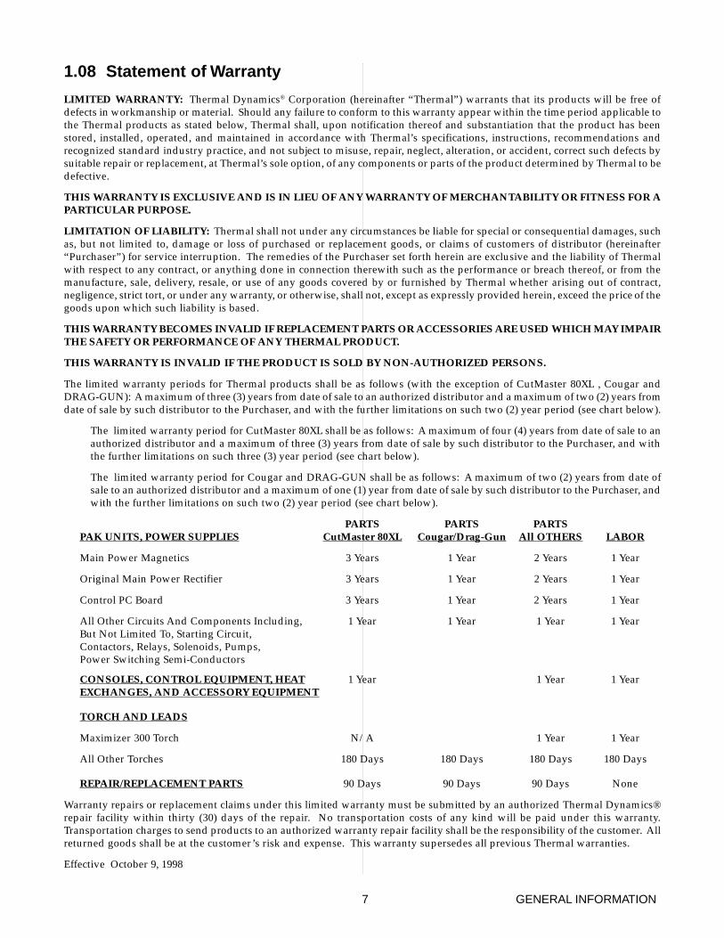
PARTS PARTS PARTSPAK UNITS, POWER SUPPLIES CutMaster 80XL Cougar/Drag-Gun All OTHERS LABOR
Main Power Magnetics 3 Years 1 Year 2 Years 1 Year
Original Main Power Rectifier 3 Years 1 Year 2 Years 1 Year
Control PC Board 3 Years 1 Year 2 Years 1 Year
All Other Circuits And Components Including, 1 Year 1 Year 1 Year 1 YearBut Not Limited To, Starting Circuit,Contactors, Relays, Solenoids, Pumps,Power Switching Semi-Conductors
CONSOLES, CONTROL EQUIPMENT, HEAT 1 Year 1 Year 1 YearEXCHANGES, AND ACCESSORY EQUIPMENT
TORCH AND LEADS
Maximizer 300 Torch N/A 1 Year 1 Year
All Other Torches 180 Days 180 Days 180 Days 180 Days
REPAIR/REPLACEMENT PARTS 90 Days 90 Days 90 Days None
Warranty repairs or replacement claims under this limited warranty must be submitted by an authorized Thermal Dynamics®repair facility within thirty (30) days of the repair. No transportation costs of any kind will be paid under this warranty.Transportation charges to send products to an authorized warranty repair facility shall be the responsibility of the customer. Allreturned goods shall be at the customer’s risk and expense. This warranty supersedes all previous Thermal warranties.
Effective October 9, 1998

GENERAL INFORMATION 8
Manual 0-2611 9 INTRODUCTION
SECTION 2:INTRODUCTION
2.01 Scope of Manual
This manual contains descriptions, operating instructionsand basic maintenance procedures for the PAK Master®
100XL Air Plasma Cutting Power Supply (CE). Serviceof this equipment is restricted to Thermal Dynamicstrained personnel; unqualified personnel are strictly cau-tioned against attempting repairs or adjustments not cov-ered in this manual, at the risk of voiding the Warranty.
Read this manual thoroughly. A complete understand-ing of the characteristics and capabilities of this equip-ment will assure the dependable operation for which itwas designed.
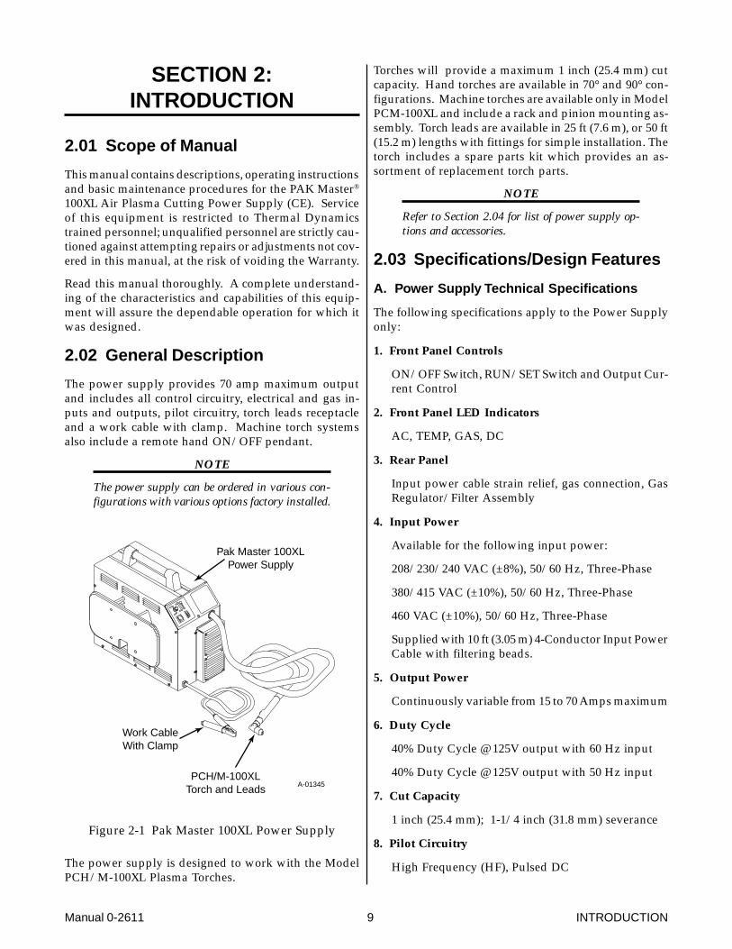
2.02 General Description
The power supply provides 70 amp maximum outputand includes all control circuitry, electrical and gas in-puts and outputs, pilot circuitry, torch leads receptacleand a work cable with clamp. Machine torch systemsalso include a remote hand ON/OFF pendant.
NOTE
The power supply can be ordered in various con-figurations with various options factory installed.
Pak Master 100XLPower Supply
PCH/M-100XLTorch and Leads
Work CableWith Clamp
A-01345
Figure 2-1 Pak Master 100XL Power Supply
The power supply is designed to work with the ModelPCH/M-100XL Plasma Torches.
Torches will provide a maximum 1 inch (25.4 mm) cutcapacity. Hand torches are available in 70° and 90° con-figurations. Machine torches are available only in ModelPCM-100XL and include a rack and pinion mounting as-sembly. Torch leads are available in 25 ft (7.6 m), or 50 ft(15.2 m) lengths with fittings for simple installation. Thetorch includes a spare parts kit which provides an as-sortment of replacement torch parts.
NOTE
Refer to Section 2.04 for list of power supply op-tions and accessories.
2.03 Specifications/Design Features
A. Power Supply Technical Specifications
The following specifications apply to the Power Supplyonly:
1. Front Panel Controls
ON/OFF Switch, RUN/SET Switch and Output Cur-rent Control
2. Front Panel LED Indicators
AC, TEMP, GAS, DC
3. Rear Panel
Input power cable strain relief, gas connection, GasRegulator/Filter Assembly
4. Input Power
Available for the following input power:
208/230/240 VAC (±8%), 50/60 Hz, Three-Phase
380/415 VAC (±10%), 50/60 Hz, Three-Phase
460 VAC (±10%), 50/60 Hz, Three-Phase
Supplied with 10 ft (3.05 m) 4-Conductor Input PowerCable with filtering beads.
5. Output Power
Continuously variable from 15 to 70 Amps maximum
6. Duty Cycle
40% Duty Cycle @ 125V output with 60 Hz input
40% Duty Cycle @ 125V output with 50 Hz input
7. Cut Capacity
1 inch (25.4 mm); 1-1/4 inch (31.8 mm) severance
8. Pilot Circuitry
High Frequency (HF), Pulsed DC
INTRODUCTION 10 Manual 0-2611
9. Weight
79 lbs (35.8 kg)
10. Overall Dimensions
18.9" (480 mm) High x 13" (330 mm) Wide x 25.5"(648 mm) Long
Overall dimensions are with handle, lead wrapbracket, and Gas Regulator/Filter Assembly installed.
B. Gas Regulator/Filter AssemblySpecifications
The following specifications apply to the Gas Regula-tor/Filter Assembly only:
1. Gas regulator maximum gauge pressure
160 psi (11 BAR or 11.03 kPa)
2. Maximum input gas pressure
125 psi (8.6 BAR or 861 kPa)
3. Filter
Coalescent type filter
2.04 Power Supply Options andAccessories
NOTE
Refer to Section 6, Parts Lists, for part numbersand ordering information.
The following are accessories that are available for thispower supply:
A. Two Stage Air Line Filter
An optional two stage air line filter is available. Thefilter will remove moisture and contaminants fromthe air stream when using compressed air. The filteris capable of filtering to at least 5 microns. The filterassembly is pre-assembled at the factory and needonly be attached to the power supply.
B. High Pressure Regulators
High pressure regulators are available for air and ni-trogen. The regulators are used to set the proper pres-sure for the type gas being used.
C. Smart Cart
Steel cart on easy rolling 10" pneumatic tires to pro-vide maximum mobility for the power supply.Handle is 3/4" tubing with hooks for storage of torchleads. A tie down strap is also included.
D. Interface Cable
NOTE
This accessory can be used only with thePCM-100XL Torches.
The interface cable is available in two lengths, 25 ft(7.6 m) and 50 ft (15.2 m). The cable is used to inter-face the power supply with an auxiliary control de-vice to provide OK-To-Move and ON/OFF signals.
Manual 0-2611 11 INSTALLATION PROCEDURES
SECTION 3:INSTALLATIONPROCEDURES
3.01 Introduction
NOTE
Depending on how the system was ordered, somePower Supply Options may already be installed.
If option(s) have been factory installed some of theinstructions may not apply. It is recommendedthat all sub-sections be read for general informa-tion.,
This Section describes installation of the Power Supplyand connecting the Torch.
These instructions apply to the Power Supply only; in-stallation procedures for the Torch, Options, and Acces-sories are given in Manuals specifically provided forthose units.
The complete installation consists of:
1. Site selection
2. Unpacking
3. Connections to Power Supply
a. Input power
b. Gas
c. Work cable
d. Torch Leads
4. Grounding
5. Operator training
3.02 Site Selection
Select a clean, dry location with good ventilation andadequate working space around all components.
NOTE
Review Important Safety Precautions (page 1) tobe sure that the selected location meets all safetyrequirements.
The power supply is fan cooled by air flow through thefront panel to the rear panel. Air flow must not be ob-structed. Provide at least 2 feet (0.61 m) in the rear andat least 6 inches (0.15 m) on each side for clearance .
Provide sufficient clearance in front of the unit to allowaccess to the front panel controls (minimum 6 inches or0.15 m).
CAUTION
Operation without proper air flow will inhibitproper cooling and reduce duty cycle.
3.03 Unpacking
NOTE
Equipment that was ordered as a system is pack-aged in one shipping carton. All options and theTorch are factory installed.
Each component of the system is packaged and protectedwith a carton and packing material to prevent damageduring shipping.
A. Power Supply
Included with each power supply is Input Power Cable,Work Cable and Clamp; Pressure Regulator/Filter As-sembly and connection hardware; Operating Manual.
B. Torch and Leads
Included with each Torch is Torch and Leads with TorchHandle Assembly, Shield Cup, Tip, Electrode, Gas Dis-tributor and all connectors installed; Torch Spare PartsKit; Operating Manual.
Machine Torches also include Metal Rack and PinionMounting Assembly, and Remote Control Hand Pendant.
C. Options and Accessories
Options and Accessories are packaged separately if notinstalled at the factory.
D. Unpacking Procedure
1. Unpack each item and remove all packing material.
NOTE
The Spare Parts Kit is shipped in the Torch LeadsStorage Area on the side of the Power Supply.
2. Locate the packing list(s) and use the list to identifyand account for each item.
3. Inspect each item for possible shipping damage. Ifdamage is evident, contact your distributor and/orshipping company before proceeding with system in-stallation.
INSTALLATION PROCEDURES 12 Manual 0-2611
3.04 Lifting Options
WARNINGS
Do not touch live electrical parts.
Disconnect input power conductors from de-en-ergized supply line before moving unit.
This unit is equipped with one handle mounted ontothe top of the enclosure for hand carrying purposes.
WARNING
FALLING EQUIPMENT can cause serious per-sonal injury and equipment damage.
• Lift unit with the handle on top of the enclosure.
• Persons only of adequate physical strength shouldlift the unit.
• Use hand cart or similar device of adequate capac-ity.
• If using a fork lift vehicle, place and secure unit ona proper skid before transporting.
• This unit has a handle mounted on top of the en-closure for hand lifting only. Be sure unit is liftedand transported safely and securely.
WARNING
HANDLE is not for mechanical lifting.
3.05 Input Power Connections
The Power Supply accepts input voltages from 208V to460V. Input can be 50 or 60 Hz, three-phase. The PowerSupply is factory wired for 380/415V three-phase input.For any other input voltage, the Power Supply must beinternally reset.
NOTE
Refer to Section 3.06, Input Voltage Selection forprocedure.
A. Input Voltage Selection
The Power Supply is factory-wired for 380/415V three-phase input. For any other input voltage, the Power Sup-ply must be changed using the procedure in Sections3.06.
B. Electrical Connections
The power source must conform to local and nationalelectric codes. Recommended circuit protection and wir-ing requirements are shown in Appendix I.
C. Opening Power Supply Enclosure
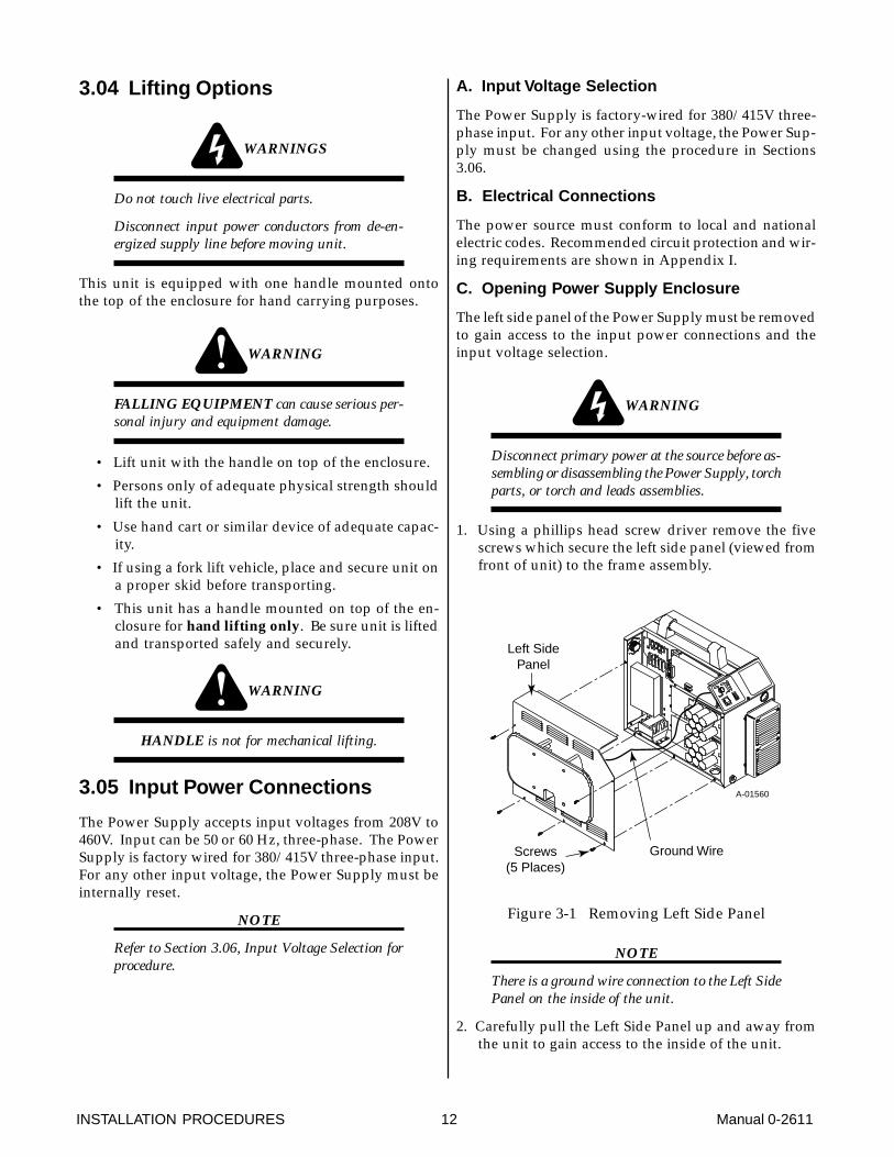
The left side panel of the Power Supply must be removedto gain access to the input power connections and theinput voltage selection.
WARNING
Disconnect primary power at the source before as-sembling or disassembling the Power Supply, torchparts, or torch and leads assemblies.
1. Using a phillips head screw driver remove the fivescrews which secure the left side panel (viewed fromfront of unit) to the frame assembly.
Screws(5 Places)
Left SidePanel
A-01560
Ground Wire
Figure 3-1 Removing Left Side Panel
NOTE
There is a ground wire connection to the Left SidePanel on the inside of the unit.
2. Carefully pull the Left Side Panel up and away fromthe unit to gain access to the inside of the unit.
Manual 0-2611 13 INSTALLATION PROCEDURES
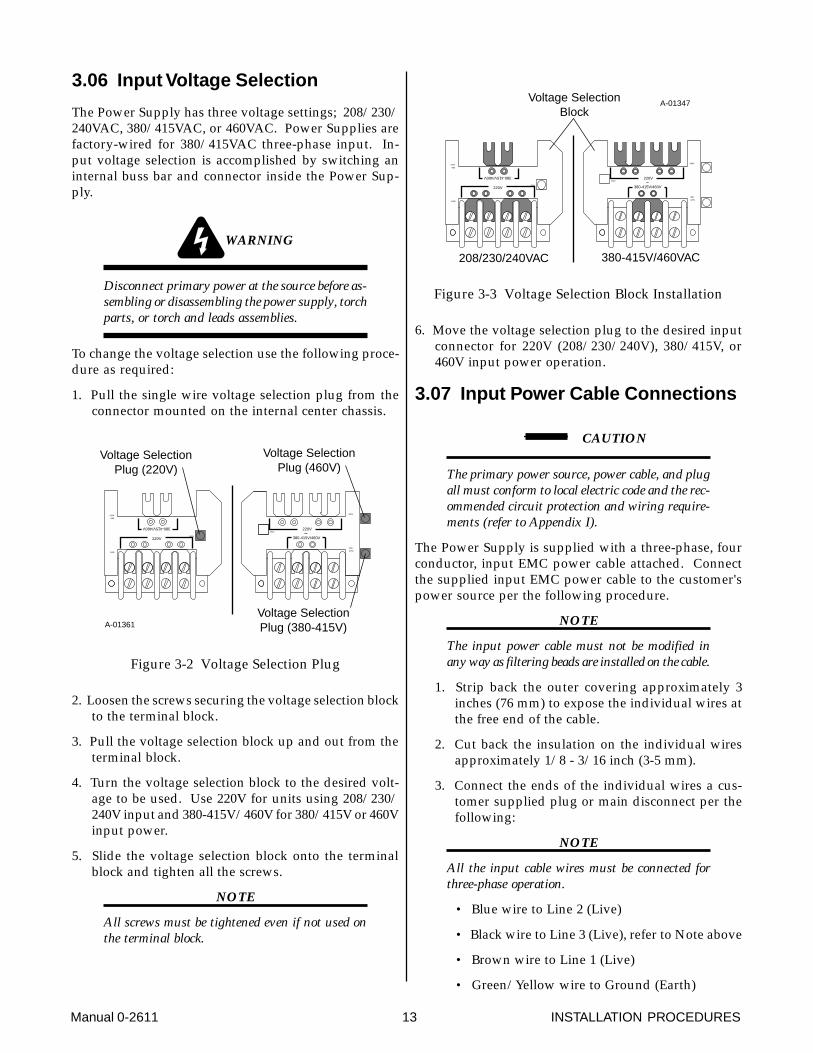
3.06 Input Voltage Selection
The Power Supply has three voltage settings; 208/230/240VAC, 380/415VAC, or 460VAC. Power Supplies arefactory-wired for 380/415VAC three-phase input. In-put voltage selection is accomplished by switching aninternal buss bar and connector inside the Power Sup-ply.
WARNING
Disconnect primary power at the source before as-sembling or disassembling the power supply, torchparts, or torch and leads assemblies.
To change the voltage selection use the following proce-dure as required:
1. Pull the single wire voltage selection plug from theconnector mounted on the internal center chassis.
380-415V/460V
220V
460V
380-
415V220V
380-
415V
460V
220V
380-415V/460V
220V
Voltage SelectionPlug (220V)
Voltage SelectionPlug (460V)
Voltage SelectionPlug (380-415V)A-01361
Figure 3-2 Voltage Selection Plug
2. Loosen the screws securing the voltage selection blockto the terminal block.
3. Pull the voltage selection block up and out from theterminal block.
4. Turn the voltage selection block to the desired volt-age to be used. Use 220V for units using 208/230/240V input and 380-415V/460V for 380/415V or 460Vinput power.
5. Slide the voltage selection block onto the terminalblock and tighten all the screws.
NOTE
All screws must be tightened even if not used onthe terminal block.
380-415V/460V
220V
460V
380-
415V
220V
208/230/240VAC
380-
415V
460V
220V
380-415V/460V
220V
380-415V/460VAC
Voltage SelectionBlock
A-01347
Figure 3-3 Voltage Selection Block Installation
6. Move the voltage selection plug to the desired inputconnector for 220V (208/230/240V), 380/415V, or460V input power operation.
3.07 Input Power Cable Connections
CAUTION
The primary power source, power cable, and plugall must conform to local electric code and the rec-ommended circuit protection and wiring require-ments (refer to Appendix I).
The Power Supply is supplied with a three-phase, fourconductor, input EMC power cable attached. Connectthe supplied input EMC power cable to the customer'spower source per the following procedure.
NOTE
The input power cable must not be modified inany way as filtering beads are installed on the cable.
1. Strip back the outer covering approximately 3inches (76 mm) to expose the individual wires atthe free end of the cable.
2. Cut back the insulation on the individual wiresapproximately 1/8 - 3/16 inch (3-5 mm).
3. Connect the ends of the individual wires a cus-tomer supplied plug or main disconnect per thefollowing:
NOTE
All the input cable wires must be connected forthree-phase operation.
• Blue wire to Line 2 (Live)
• Black wire to Line 3 (Live), refer to Note above
• Brown wire to Line 1 (Live)
• Green/Yellow wire to Ground (Earth)
INSTALLATION PROCEDURES 14 Manual 0-2611
CAUTION
The primary power source, power cable, and plugall must conform to local electric code and the rec-ommended circuit protection and wiring require-ments (refer to Appendix I).
3.08 Gas Connections
A. Gas Requirements
WARNING
This unit not to be used with oxygen (O2).
Gases: Compressed Air or Nitrogen (N2) Only
Pressure: 70 psi (4.8 BAR or 482 kPa)
CAUTION
Maximum input gas pressure must not exceed 125psi (8.6 BAR or 861 kPa)
Flow: Cutting - 400 scfh (188.7 lpm)
Gouging - 400 scfh (188.7 lpm)
CAUTION
Air supply must be free of oil, moisture, and othercontaminants. Excessive oil and moisture maycause double-arcing, rapid tip wear, or even com-plete torch failure. Contaminants may cause poorcutting performance and rapid electrode wear.
B. Checking Air Quality
To test the quality of air, place the RUN/SET switch toSET position, place a welding filter lens in front of thetorch and turn on the gas. Any oil or moisture in the airwill be visible on the lens. Do not initiate an arc!
C. Gas Connection
The gas supply is connected to the rear of the PowerSupply. The connection is the same for compressed airor high pressure gas cylinders.
CAUTION
The air supply must be free of oil, moisture, andother contaminants. Excessive oil and moisturemay cause double-arcing, rapid tip wear, or evencomplete torch failure. Contaminants may causepoor cutting performance and rapid electrode wear.
An air line filter is supplied as part of the Pressure Regu-lator/Filter Assembly installed on the rear of the unit.
NOTE
Filtering is required when using air from a com-pressor to insure that moisture and debris fromthe supply hose does not enter the torch. It is rec-ommended to order the Optional Two Stage AirLine Filter for improved air filtering.
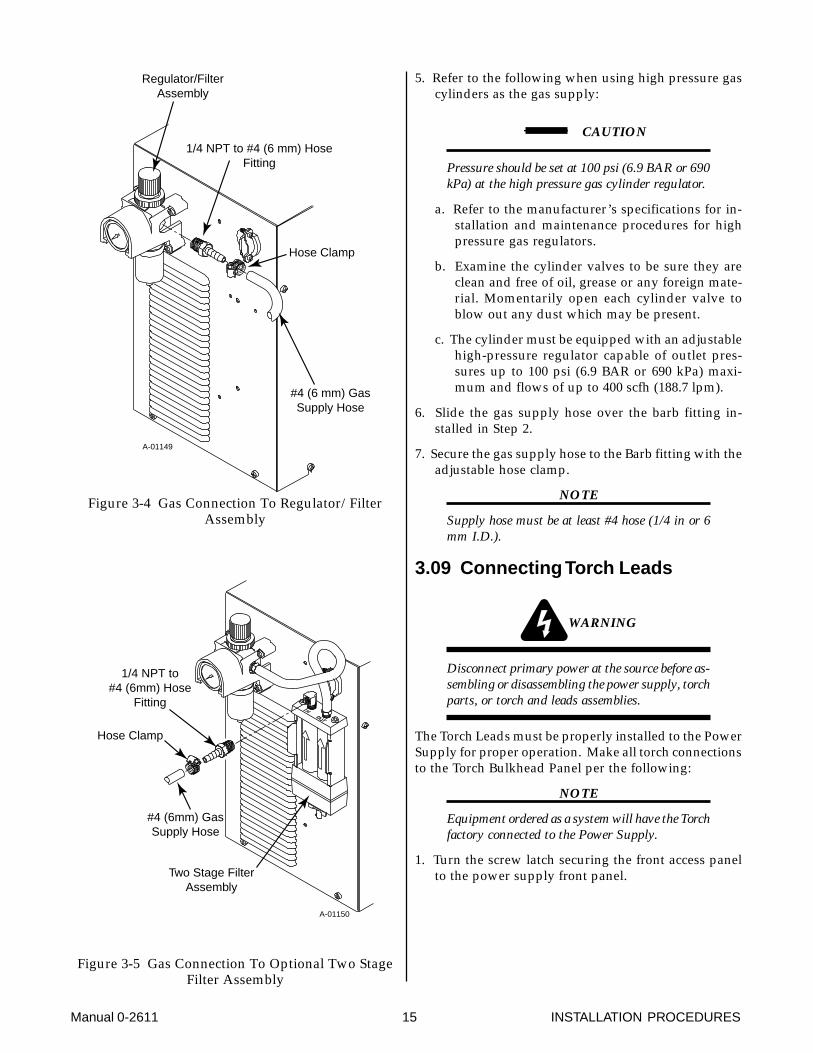
1. Locate the 1/4 NPT to #4 (6mm) hose barb fittingshipped inside the Torch Spare Parts Kit.
NOTE
A barb fitting is provided for connection of thegas supply hose to the rear of the Power Supply.The fitting is placed in the Spare Parts Kit forshipment.
2. Depending on the options installed at the factory, in-stall the supplied barb fitting into the input of theRegulator/Filter Assembly or the Optional Two StageAir Filter Assembly.
3. Tighten the barb fitting.
4. Place an adjustable hose clamp, 1/4" (6.35mm) to 5/8" (15.88mm)) over the gas supply hose.
Manual 0-2611 15 INSTALLATION PROCEDURES
Regulator/FilterAssembly
1/4 NPT to #4 (6 mm) HoseFitting
#4 (6 mm) GasSupply Hose
Hose Clamp
A-01149
Figure 3-4 Gas Connection To Regulator/FilterAssembly
Two Stage FilterAssembly
1/4 NPT to#4 (6mm) Hose
Fitting
#4 (6mm) GasSupply Hose
Hose Clamp
A-01150
Figure 3-5 Gas Connection To Optional Two StageFilter Assembly
5. Refer to the following when using high pressure gascylinders as the gas supply:
CAUTION
Pressure should be set at 100 psi (6.9 BAR or 690kPa) at the high pressure gas cylinder regulator.
a. Refer to the manufacturer’s specifications for in-stallation and maintenance procedures for highpressure gas regulators.
b. Examine the cylinder valves to be sure they areclean and free of oil, grease or any foreign mate-rial. Momentarily open each cylinder valve toblow out any dust which may be present.
c. The cylinder must be equipped with an adjustablehigh-pressure regulator capable of outlet pres-sures up to 100 psi (6.9 BAR or 690 kPa) maxi-mum and flows of up to 400 scfh (188.7 lpm).
6. Slide the gas supply hose over the barb fitting in-stalled in Step 2.
7. Secure the gas supply hose to the Barb fitting with theadjustable hose clamp.
NOTE
Supply hose must be at least #4 hose (1/4 in or 6mm I.D.).
3.09 Connecting Torch Leads
WARNING
Disconnect primary power at the source before as-sembling or disassembling the power supply, torchparts, or torch and leads assemblies.
The Torch Leads must be properly installed to the PowerSupply for proper operation. Make all torch connectionsto the Torch Bulkhead Panel per the following:
NOTE
Equipment ordered as a system will have the Torchfactory connected to the Power Supply.
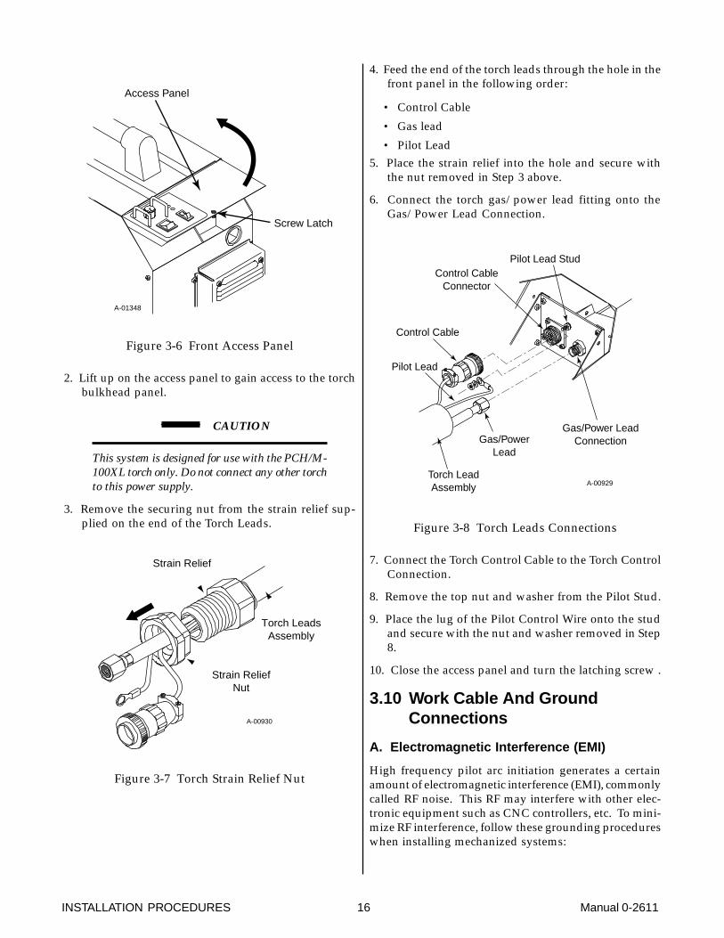
1. Turn the screw latch securing the front access panelto the power supply front panel.
INSTALLATION PROCEDURES 16 Manual 0-2611
Access Panel
Screw Latch
A-01348
Figure 3-6 Front Access Panel
2. Lift up on the access panel to gain access to the torchbulkhead panel.
CAUTION
This system is designed for use with the PCH/M-100XL torch only. Do not connect any other torchto this power supply.
3. Remove the securing nut from the strain relief sup-plied on the end of the Torch Leads.
A-00930
Strain Relief
Strain ReliefNut
Torch LeadsAssembly
Figure 3-7 Torch Strain Relief Nut
4. Feed the end of the torch leads through the hole in thefront panel in the following order:
• Control Cable
• Gas lead
• Pilot Lead5. Place the strain relief into the hole and secure with
the nut removed in Step 3 above.
6. Connect the torch gas/power lead fitting onto theGas/Power Lead Connection.
Control Cable
Pilot Lead
Torch LeadAssembly
Gas/PowerLead
Control CableConnector
Pilot Lead Stud
Gas/Power LeadConnection
A-00929
Figure 3-8 Torch Leads Connections
7. Connect the Torch Control Cable to the Torch ControlConnection.
8. Remove the top nut and washer from the Pilot Stud.
9. Place the lug of the Pilot Control Wire onto the studand secure with the nut and washer removed in Step8.
10. Close the access panel and turn the latching screw .
3.10 Work Cable And GroundConnections
A. Electromagnetic Interference (EMI)
High frequency pilot arc initiation generates a certainamount of electromagnetic interference (EMI), commonlycalled RF noise. This RF may interfere with other elec-tronic equipment such as CNC controllers, etc. To mini-mize RF interference, follow these grounding procedureswhen installing mechanized systems:
Manual 0-2611 17 INSTALLATION PROCEDURES
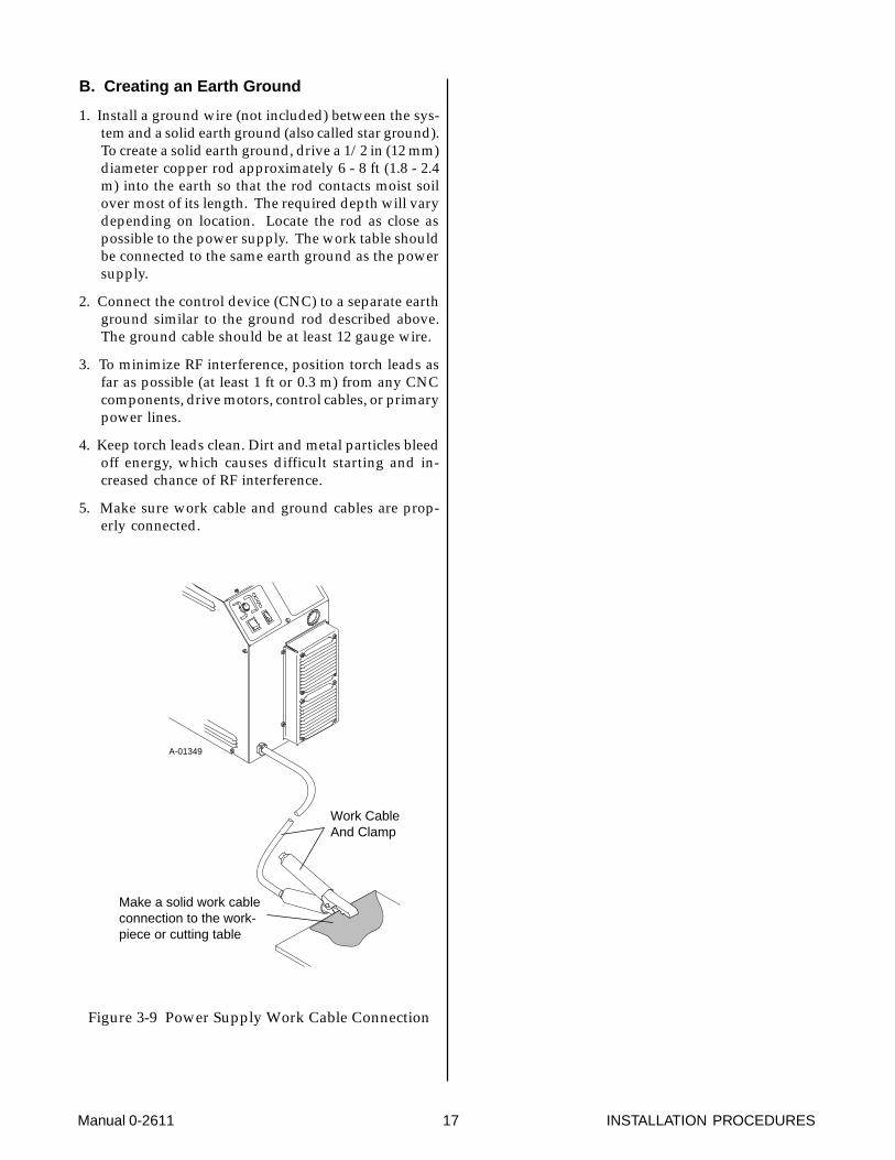
B. Creating an Earth Ground
1. Install a ground wire (not included) between the sys-tem and a solid earth ground (also called star ground).To create a solid earth ground, drive a 1/2 in (12 mm)diameter copper rod approximately 6 - 8 ft (1.8 - 2.4m) into the earth so that the rod contacts moist soilover most of its length. The required depth will varydepending on location. Locate the rod as close aspossible to the power supply. The work table shouldbe connected to the same earth ground as the powersupply.
2. Connect the control device (CNC) to a separate earthground similar to the ground rod described above.The ground cable should be at least 12 gauge wire.
3. To minimize RF interference, position torch leads asfar as possible (at least 1 ft or 0.3 m) from any CNCcomponents, drive motors, control cables, or primarypower lines.
4. Keep torch leads clean. Dirt and metal particles bleedoff energy, which causes difficult starting and in-creased chance of RF interference.
5. Make sure work cable and ground cables are prop-erly connected.
Make a solid work cableconnection to the work-piece or cutting table
Work CableAnd Clamp
A-01349
Figure 3-9 Power Supply Work Cable Connection

INSTALLATION PROCEDURES 18 Manual 0-2611
Manual 0-2611 19 OPERATION
SECTION 4:OPERATION
4.01 Introduction
This Section provides a description of the Power Supplyoperating controls and procedures. Identification of theFront and Rear Panel components is followed by oper-ating procedures.
4.02 Functional Overview
The Power Supply provides a degree of operating flex-ibility and the use of simple controls.
4.03 Operating Controls
This subsection provides specific functional descriptionsof the Power Supply operating controls and indicators.
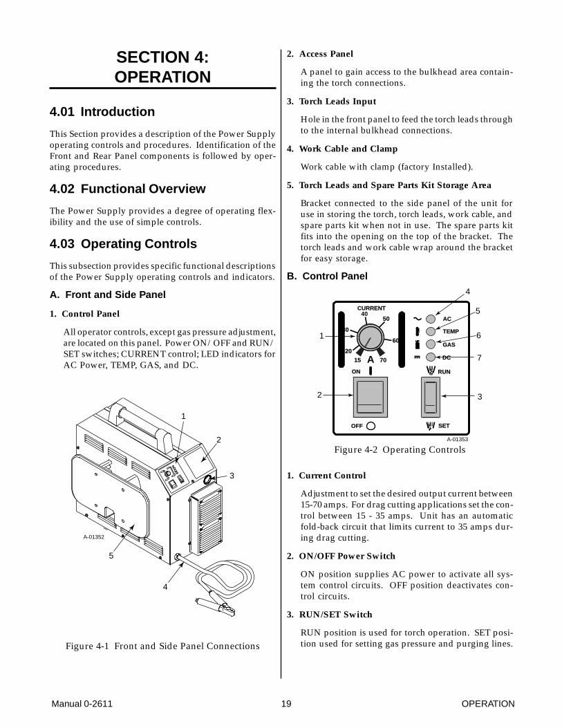
A. Front and Side Panel
1. Control Panel
All operator controls, except gas pressure adjustment,are located on this panel. Power ON/OFF and RUN/SET switches; CURRENT control; LED indicators forAC Power, TEMP, GAS, and DC.
1
3
4
5
2
A-01352
Figure 4-1 Front and Side Panel Connections
2. Access Panel
A panel to gain access to the bulkhead area contain-ing the torch connections.
3. Torch Leads Input
Hole in the front panel to feed the torch leads throughto the internal bulkhead connections.
4. Work Cable and Clamp
Work cable with clamp (factory Installed).
5. Torch Leads and Spare Parts Kit Storage Area
Bracket connected to the side panel of the unit foruse in storing the torch, torch leads, work cable, andspare parts kit when not in use. The spare parts kitfits into the opening on the top of the bracket. Thetorch leads and work cable wrap around the bracketfor easy storage.
B. Control Panel
TEMP
AC
GAS
DC
SET
RUNON
OFF
A
CURRENT
1
2 3
4
5
6
7
A-01353
30
20
50
70
60
15
40
Figure 4-2 Operating Controls
1. Current Control
Adjustment to set the desired output current between15-70 amps. For drag cutting applications set the con-trol between 15 - 35 amps. Unit has an automaticfold-back circuit that limits current to 35 amps dur-ing drag cutting.
2. ON/OFF Power Switch
ON position supplies AC power to activate all sys-tem control circuits. OFF position deactivates con-trol circuits.
3. RUN/SET Switch
RUN position is used for torch operation. SET posi-tion used for setting gas pressure and purging lines.
OPERATION 20 Manual 0-2611
4. AC Power Indicator
Green LED indicator will blink ON then OFF for ap-proximately eight seconds and then stay ON afterthe ON/OFF power switch is set to ON. Indicatesoperating power is present in the unit..
5. TEMP Indicator
Normally OFF. Yellow LED indicator will come ONwhen the internal temperature senors detect tempera-tures above normal limits. The unit should be al-lowed to cool before continuing operation.
6. GAS Indicator
Green LED indicator will come ON when the inputgas pressure is set to 45 psi (3.1 BAR or 310 kPa) orhigher. Indicator will be OFF when the pressure fallsbelow 45 psi (3.1 BAR or 310 kPa).
7. DC Indicator
Green LED indicator will come ON while the torchswitch is pressed.
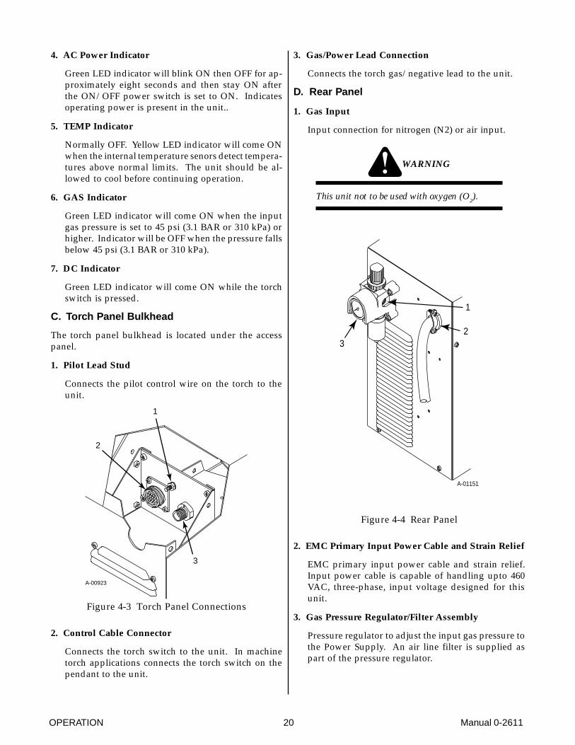
C. Torch Panel Bulkhead
The torch panel bulkhead is located under the accesspanel.
1. Pilot Lead Stud
Connects the pilot control wire on the torch to theunit.
2
1
3
A-00923
Figure 4-3 Torch Panel Connections
2. Control Cable Connector
Connects the torch switch to the unit. In machinetorch applications connects the torch switch on thependant to the unit.
3. Gas/Power Lead Connection
Connects the torch gas/negative lead to the unit.
D. Rear Panel
1. Gas Input
Input connection for nitrogen (N2) or air input.
WARNING
This unit not to be used with oxygen (O2).
1
23
A-01151
Figure 4-4 Rear Panel
2. EMC Primary Input Power Cable and Strain Relief
EMC primary input power cable and strain relief.Input power cable is capable of handling upto 460VAC, three-phase, input voltage designed for thisunit.
3. Gas Pressure Regulator/Filter Assembly
Pressure regulator to adjust the input gas pressure tothe Power Supply. An air line filter is supplied aspart of the pressure regulator.
Manual 0-2611 21 OPERATION
A-01152
1
3
4
2
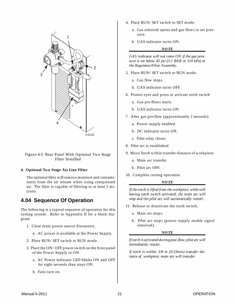
Figure 4-5 Rear Panel With Optional Two StageFilter Installed
4. Optional Two Stage Air Line Filter
The optional filter will remove moisture and contami-nants from the air stream when using compressedair. The filter is capable of filtering to at least 5 mi-crons.
4.04 Sequence Of Operation
The following is a typical sequence of operation for thiscutting system. Refer to Appendix II for a block dia-gram.
1. Close main power source disconnect.
a. AC power is available at the Power Supply.
2. Place RUN/SET switch to RUN mode.
3. Place the ON/OFF power switch on the front panelof the Power Supply to ON.
a. AC Power indicator LED blinks ON and OFFfor eight seconds then stays ON.
b. Fans turn on.
4. Place RUN/SET switch to SET mode.
a. Gas solenoid opens and gas flows to set pres-sure.
b. GAS indicator turns ON.
NOTE
GAS indicator will not come ON if the gas pres-sure is set below 45 psi (3.1 BAR or 310 kPa) atthe Regulator/Filter Assembly.
5. Place RUN/SET switch to RUN mode.
a. Gas flow stops.
b. GAS indicator turns OFF.
6. Protect eyes and press or activate torch switch
a. Gas pre-flows starts.
b. GAS indicator turns ON.
7. After gas pre-flow (approximately 2 seconds)
a. Power supply enabled.
b. DC indicator turns ON.
c. Pilot relay closes.
8. Pilot arc is established
9. Move Torch within transfer distance of workpiece.
a. Main arc transfer.
b. Pilot arc OFF.
10. Complete cutting operation
NOTE
If the torch is lifted from the workpiece, while stillhaving torch switch activated, the main arc willstop and the pilot arc will automatically restart.
11. Release or deactivate the torch switch.
a. Main arc stops.
b. Pilot arc stops (power supply enable signalremoved).
NOTE
If torch is activated during post-flow, pilot arc willimmediately restart.
If torch is within 3/8 in (9.53mm) transfer dis-tance of workpiece, main arc will transfer.
OPERATION 22 Manual 0-2611
12. Gas will flow for 15 seconds (post-flow).
a. Gas solenoid closes
b. Gas flow stops.
c. GAS indicator turns OFF.
13. Place the ON/OFF power switch on the frontpanel of the unit to OFF
a. AC Power indicator turns OFF.
b. Fans turn OFF.
14. Place the main power disconnect to open.
a. Main AC power is removed from the system.
4.05 Preparations for Operating
Follow this set-up procedure each time the system is op-erated:
WARNING
Disconnect primary power at the source before dis-assembling the power supply, torch, or torch leads.
A. Torch Parts Selection
Check the torch for proper assembly and appropriatefront end torch parts. The torch parts (shield cup, tipand electrode) must correspond with the type of opera-tion (cutting or gouging). Refer to the Instruction Manualsupplied with the Torch Assembly for proper parts se-lection.
B. Check primary power source as follows:
1. Check the power source for proper input voltage.Make sure the input power source meets the powerrequirements for the unit per Section 2.03-A-4, Speci-fications/Design Features.
2. Connect the input power cable (or close the main dis-connect switch) to supply power to the system.
C. Gas Selection
Select desired gas (air or nitrogen). Make sure gas sourcemeets pressure and flow requirements (refer to Section3.08, Gas Connections). Check connection and turn gassupply on.
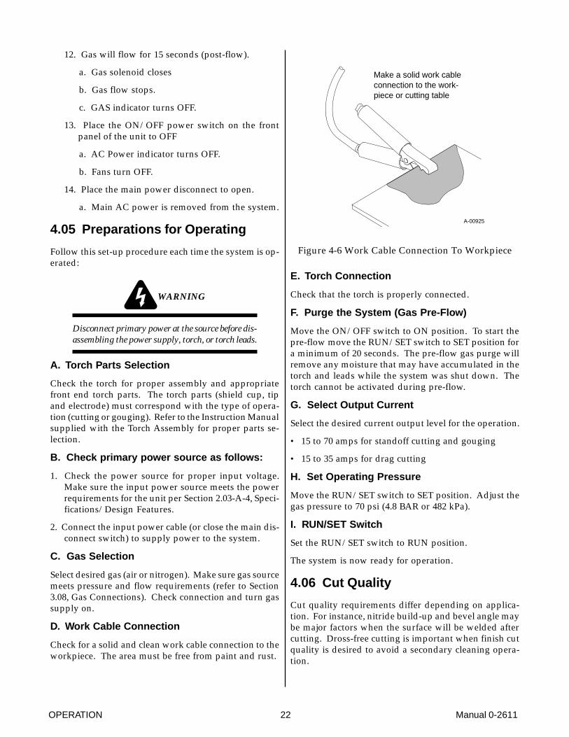
D. Work Cable Connection
Check for a solid and clean work cable connection to theworkpiece. The area must be free from paint and rust.
Make a solid work cableconnection to the work-piece or cutting table
A-00925
Figure 4-6 Work Cable Connection To Workpiece
E. Torch Connection
Check that the torch is properly connected.
F. Purge the System (Gas Pre-Flow)
Move the ON/OFF switch to ON position. To start thepre-flow move the RUN/SET switch to SET position fora minimum of 20 seconds. The pre-flow gas purge willremove any moisture that may have accumulated in thetorch and leads while the system was shut down. Thetorch cannot be activated during pre-flow.
G. Select Output Current
Select the desired current output level for the operation.
• 15 to 70 amps for standoff cutting and gouging
• 15 to 35 amps for drag cutting
H. Set Operating Pressure
Move the RUN/SET switch to SET position. Adjust thegas pressure to 70 psi (4.8 BAR or 482 kPa).
I. RUN/SET Switch
Set the RUN/SET switch to RUN position.
The system is now ready for operation.
4.06 Cut Quality
Cut quality requirements differ depending on applica-tion. For instance, nitride build-up and bevel angle maybe major factors when the surface will be welded aftercutting. Dross-free cutting is important when finish cutquality is desired to avoid a secondary cleaning opera-tion.
Manual 0-2611 23 OPERATION
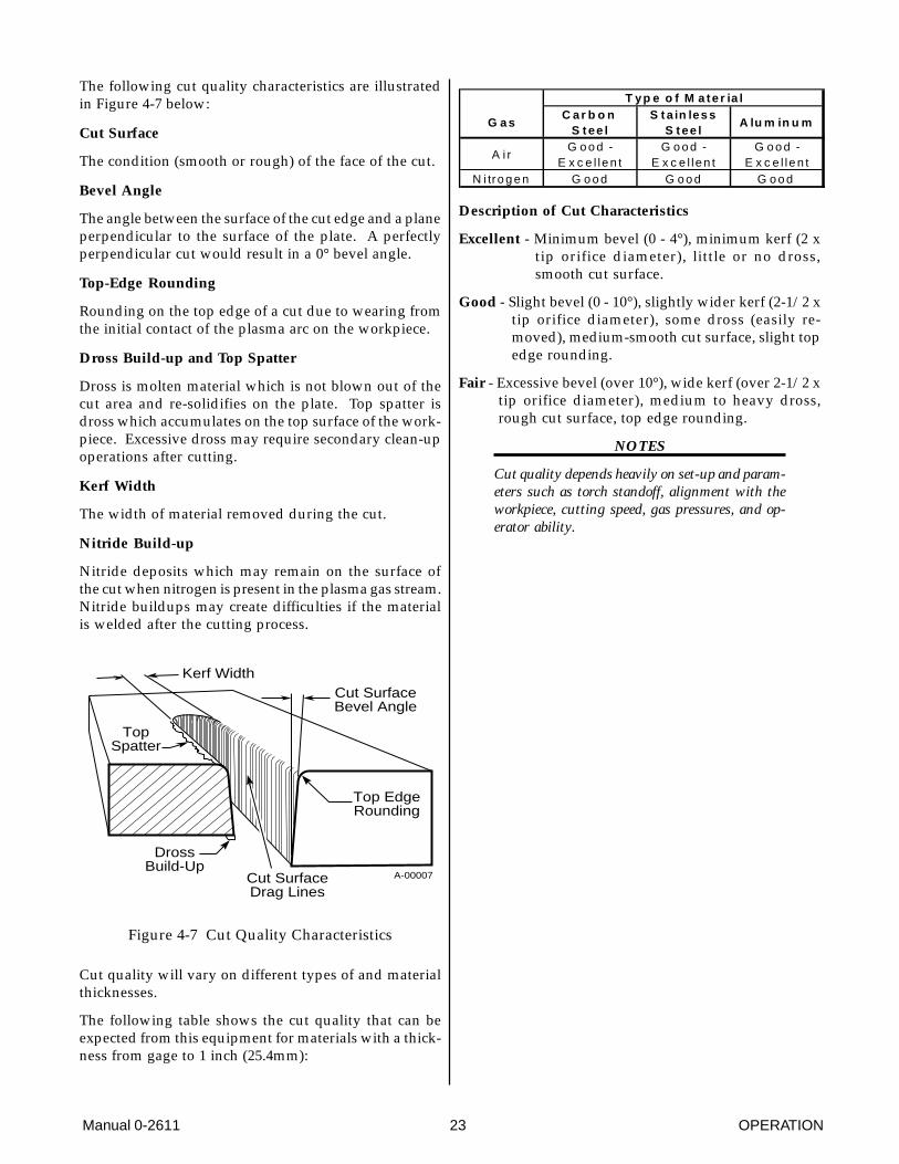
The following cut quality characteristics are illustratedin Figure 4-7 below:
Cut Surface
The condition (smooth or rough) of the face of the cut.
Bevel Angle
The angle between the surface of the cut edge and a planeperpendicular to the surface of the plate. A perfectlyperpendicular cut would result in a 0° bevel angle.
Top-Edge Rounding
Rounding on the top edge of a cut due to wearing fromthe initial contact of the plasma arc on the workpiece.
Dross Build-up and Top Spatter
Dross is molten material which is not blown out of thecut area and re-solidifies on the plate. Top spatter isdross which accumulates on the top surface of the work-piece. Excessive dross may require secondary clean-upoperations after cutting.
Kerf Width
The width of material removed during the cut.
Nitride Build-up
Nitride deposits which may remain on the surface ofthe cut when nitrogen is present in the plasma gas stream.Nitride buildups may create difficulties if the materialis welded after the cutting process.
Kerf WidthCut SurfaceBevel Angle
Top EdgeRounding
Cut SurfaceDrag Lines
DrossBuild-Up
TopSpatter
A-00007
Figure 4-7 Cut Quality Characteristics
Cut quality will vary on different types of and materialthicknesses.
The following table shows the cut quality that can beexpected from this equipment for materials with a thick-ness from gage to 1 inch (25.4mm):
T yp e o f M a te r ia l
G a sC a r b o n
S t ee lS t a in les s
S t ee lA lu m in u m
A i rG o o d -
E x c e l le n tG o o d -
E x c e l le n tG o o d -
E x c e l le n tN i tro g e n G o o d G o o d G o o d
Description of Cut Characteristics
Excellent - Minimum bevel (0 - 4°), minimum kerf (2 xtip orifice diameter), little or no dross,smooth cut surface.
Good - Slight bevel (0 - 10°), slightly wider kerf (2-1/2 xtip orifice diameter), some dross (easily re-moved), medium-smooth cut surface, slight topedge rounding.
Fair - Excessive bevel (over 10°), wide kerf (over 2-1/2 xtip orifice diameter), medium to heavy dross,rough cut surface, top edge rounding.
NOTES
Cut quality depends heavily on set-up and param-eters such as torch standoff, alignment with theworkpiece, cutting speed, gas pressures, and op-erator ability.

OPERATION 24 Manual 0-2611
Manual 0-2611 25 SERVICE
SECTION 5:CUSTOMER/OPERATOR
SERVICE
5.01 Introduction
This Section describes basic maintenance procedures per-formable by operating personnel. No other adjustmentsor repairs are to be attempted by other than ThermalDynamics Trained personnel.
For major troubleshooting and parts replacement pro-cedures refer to PAK Master 100XL Power Supply(EMC) Service Manual 0-2612.
5.02 General Maintenance
WARNING
Disconnect primary power to the system beforedisassembling the torch, leads, or power supply.
The only routine maintenance required for the powersupply is a thorough cleaning and inspection, with thefrequency depending on the usage and the operating en-vironment.
CAUTION
Do not blow air into the power supply duringcleaning. Blowing air into the unit can cause metalparticles to interfere with sensitive electrical com-ponents and cause damage to the unit.
To clean the unit, open the enclosure (refer to Section5.05-A, Opening Enclosure) and use a vacuum cleanerto remove any accumulated dirt and dust. The unitshould also be wiped clean. If necessary, solvents thatare recommended for cleaning electrical apparatus maybe used.
5.03 Common Operating Problems
WARNINGS
Disconnect primary power at the source before dis-assembling the power supply, torch, or torch leads.
Frequently review the Important Safety Precau-tions (page 1). Be sure the operator is equippedwith proper gloves, clothing, eye and ear protec-tion. Make sure no part of the operator’s bodycomes into contact with the workpiece while thetorch is activated.
CAUTION
Sparks from the cutting process can cause dam-age to coated, painted, and other surfaces such asglass, plastic and metal.
NOTE
Handle torch leads with care and protect them fromdamage.
A. Piloting
Piloting is harder on parts life than actual cutting be-cause the pilot arc is directed from the electrode to thetip rather than to a workpiece. Whenever possible, avoidexcessive pilot arc time to improve parts life.
B. Torch Standoff
Improper standoff (the distance between the torch tipand workpiece) can adversely affect tip life as well asshield cup life. Standoff may also significantly affect thebevel angle. Reducing standoff will generally result in amore square cut.
C. Edge Starting
For edge starts, hold the torch perpendicular to the work-piece with the front of the tip at the edge of the work-piece at the point where the cut is to start. When startingat the edge of the plate, do not pause at the edge andforce the arc to "reach" for the edge of the metal. Estab-lish the cutting arc as quickly as possible.
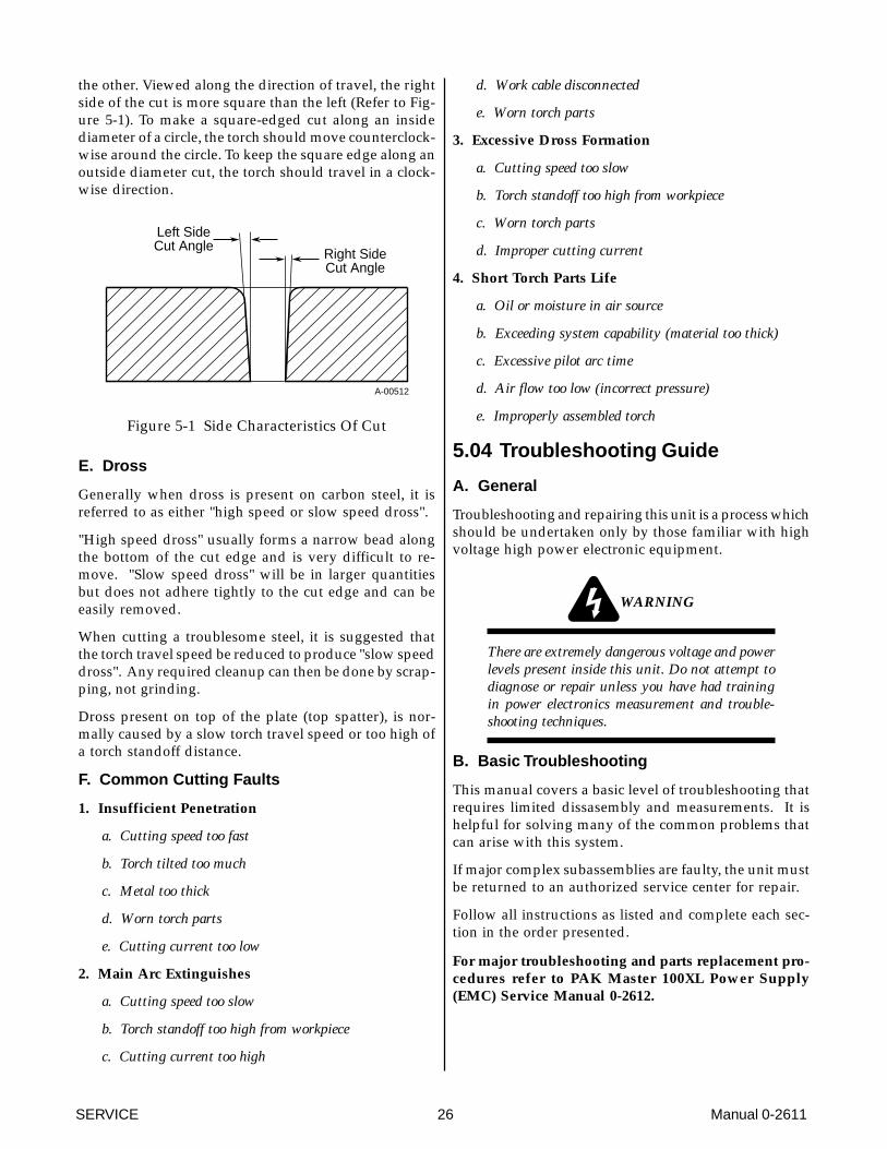
D. Direction of Cut
In the torches, the plasma gas stream swirls as it leavesthe torch to maintain a smooth column of gas. This swirleffect results in one side of a cut being more square than
SERVICE 26 Manual 0-2611
the other. Viewed along the direction of travel, the rightside of the cut is more square than the left (Refer to Fig-ure 5-1). To make a square-edged cut along an insidediameter of a circle, the torch should move counterclock-wise around the circle. To keep the square edge along anoutside diameter cut, the torch should travel in a clock-wise direction.
Right SideCut Angle
Left SideCut Angle
A-00512
Figure 5-1 Side Characteristics Of Cut
E. Dross
Generally when dross is present on carbon steel, it isreferred to as either "high speed or slow speed dross".
"High speed dross" usually forms a narrow bead alongthe bottom of the cut edge and is very difficult to re-move. "Slow speed dross" will be in larger quantitiesbut does not adhere tightly to the cut edge and can beeasily removed.
When cutting a troublesome steel, it is suggested thatthe torch travel speed be reduced to produce "slow speeddross". Any required cleanup can then be done by scrap-ping, not grinding.
Dross present on top of the plate (top spatter), is nor-mally caused by a slow torch travel speed or too high ofa torch standoff distance.
F. Common Cutting Faults
1. Insufficient Penetration
a. Cutting speed too fast
b. Torch tilted too much
c. Metal too thick
d. Worn torch parts
e. Cutting current too low
2. Main Arc Extinguishes
a. Cutting speed too slow
b. Torch standoff too high from workpiece
c. Cutting current too high
d. Work cable disconnected
e. Worn torch parts
3. Excessive Dross Formation
a. Cutting speed too slow
b. Torch standoff too high from workpiece
c. Worn torch parts
d. Improper cutting current
4. Short Torch Parts Life
a. Oil or moisture in air source
b. Exceeding system capability (material too thick)
c. Excessive pilot arc time
d. Air flow too low (incorrect pressure)
e. Improperly assembled torch
5.04 Troubleshooting Guide
A. General
Troubleshooting and repairing this unit is a process whichshould be undertaken only by those familiar with highvoltage high power electronic equipment.
WARNING
There are extremely dangerous voltage and powerlevels present inside this unit. Do not attempt todiagnose or repair unless you have had trainingin power electronics measurement and trouble-shooting techniques.
B. Basic Troubleshooting
This manual covers a basic level of troubleshooting thatrequires limited dissasembly and measurements. It ishelpful for solving many of the common problems thatcan arise with this system.
If major complex subassemblies are faulty, the unit mustbe returned to an authorized service center for repair.
Follow all instructions as listed and complete each sec-tion in the order presented.
For major troubleshooting and parts replacement pro-cedures refer to PAK Master 100XL Power Supply(EMC) Service Manual 0-2612.
Manual 0-2611 27 SERVICE
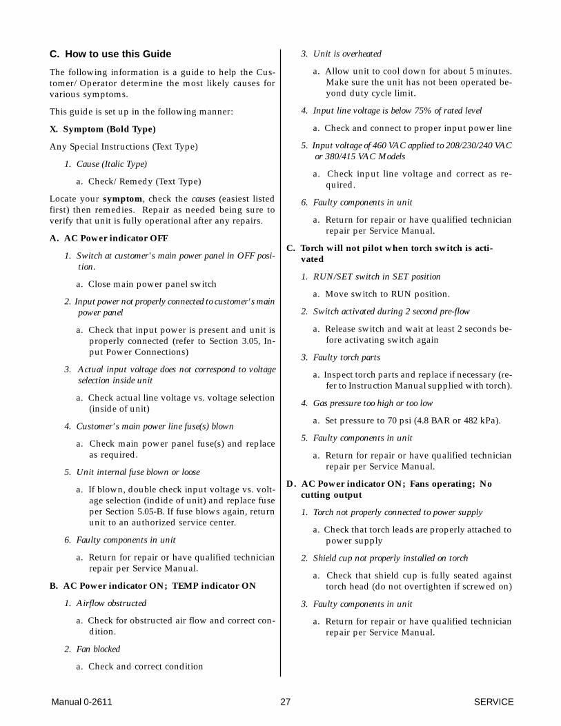
C. How to use this Guide
The following information is a guide to help the Cus-tomer/Operator determine the most likely causes forvarious symptoms.
This guide is set up in the following manner:
X. Symptom (Bold Type)
Any Special Instructions (Text Type)
1. Cause (Italic Type)
a. Check/Remedy (Text Type)
Locate your symptom, check the causes (easiest listedfirst) then remedies. Repair as needed being sure toverify that unit is fully operational after any repairs.
A. AC Power indicator OFF
1. Switch at customer's main power panel in OFF posi-tion.
a. Close main power panel switch
2. Input power not properly connected to customer's mainpower panel
a. Check that input power is present and unit isproperly connected (refer to Section 3.05, In-put Power Connections)
3. Actual input voltage does not correspond to voltageselection inside unit
a. Check actual line voltage vs. voltage selection(inside of unit)
4. Customer's main power line fuse(s) blown
a. Check main power panel fuse(s) and replaceas required.
5. Unit internal fuse blown or loose
a. If blown, double check input voltage vs. volt-age selection (indide of unit) and replace fuseper Section 5.05-B. If fuse blows again, returnunit to an authorized service center.
6. Faulty components in unit
a. Return for repair or have qualified technicianrepair per Service Manual.
B. AC Power indicator ON; TEMP indicator ON
1. Airflow obstructed
a. Check for obstructed air flow and correct con-dition.
2. Fan blocked
a. Check and correct condition
3. Unit is overheated
a. Allow unit to cool down for about 5 minutes.Make sure the unit has not been operated be-yond duty cycle limit.
4. Input line voltage is below 75% of rated level
a. Check and connect to proper input power line
5. Input voltage of 460 VAC applied to 208/230/240 VACor 380/415 VAC Models
a. Check input line voltage and correct as re-quired.
6. Faulty components in unit
a. Return for repair or have qualified technicianrepair per Service Manual.
C. Torch will not pilot when torch switch is acti-vated
1. RUN/SET switch in SET position
a. Move switch to RUN position.
2. Switch activated during 2 second pre-flow
a. Release switch and wait at least 2 seconds be-fore activating switch again
3. Faulty torch parts
a. Inspect torch parts and replace if necessary (re-fer to Instruction Manual supplied with torch).
4. Gas pressure too high or too low
a. Set pressure to 70 psi (4.8 BAR or 482 kPa).
5. Faulty components in unit
a. Return for repair or have qualified technicianrepair per Service Manual.
D. AC Power indicator ON; Fans operating; Nocutting output
1. Torch not properly connected to power supply
a. Check that torch leads are properly attached topower supply
2. Shield cup not properly installed on torch
a. Check that shield cup is fully seated againsttorch head (do not overtighten if screwed on)
3. Faulty components in unit
a. Return for repair or have qualified technicianrepair per Service Manual.
SERVICE 28 Manual 0-2611
E. Low cutting output with no control
1. Incorrect setting of CURRENT control
a. Check and adjusted to proper setting.
2. Faulty components in unit
a. Return for repair or have qualified technicianrepair per Service Manual.
F. Limited output with no control
1. Poor input or output connections
a. Check all input and output connections.
2. Incorrect setting of CURRENT control
a. Check and adjusted to proper setting.
3. Faulty components in unit
a. Return for repair or have qualified technicianrepair per Service Manual.
G. Erractic or improper cutting output
1. Poor input or output connections
a. Check all input and output connections.
2. Incorrect type and size cable on input or output
a. Use proper type and size cables.
H. AC Power indicator ON; Cutting output avail-able; Fans not operating,
1. Fan blades blocked
a. Check and clear blades.
2. Faulty components in unit
a. Return for repair or have qualified technicianrepair per Service Manual.
I. AC POWER indicator ON; Fans operate; No gasflow
1. Gas not connected or pressure too low
a. Check source for at least 70 psi (4.8 BAR).
2. Faulty components in unit
a. Return for repair or have qualified technicianrepair per Service Manual.
J. Torch cuts but not adequately
1. Current set too low
a. Increase current setting.
2. Torch is being moved too fast across workpiece
a. Reduce cutting speed (refer to InstructionManual supplied with torch.
3. Excessive oil or moisture in torch
a. Hold torch 1/8 inch (3 mm) from clean surfacewhile purging and observe oil or moisturebuildup (do not activate torch)
5.05 Power Supply PartsReplacement
WARNING
Disconnect primary power to the system beforedisassembling the torch, leads, or power supply.
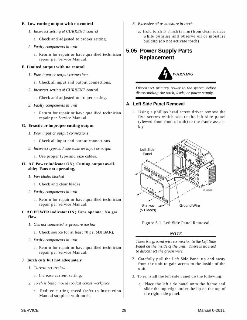
A. Left Side Panel Removal
1. Using a phillips head screw driver remove thefive screws which secure the left side panel(viewed from front of unit) to the frame assem-bly.
Screws(5 Places)
Left SidePanel
A-01560
Ground Wire
Figure 5-1 Left Side Panel Removal
NOTE
There is a ground wire connection to the Left SidePanel on the inside of the unit. There is no needto disconnect the groun wire.
2. Carefully pull the Left Side Panel up and awayfrom the unit to gain access to the inside of theunit.
3. To reinstall the left side panel do the following:
a. Place the left side panel onto the frame andslide the top edge under the lip on the top ofthe right side panel.
Manual 0-2611 29 SERVICE
b. Reinstall all the screws to secure the left sidepanel.
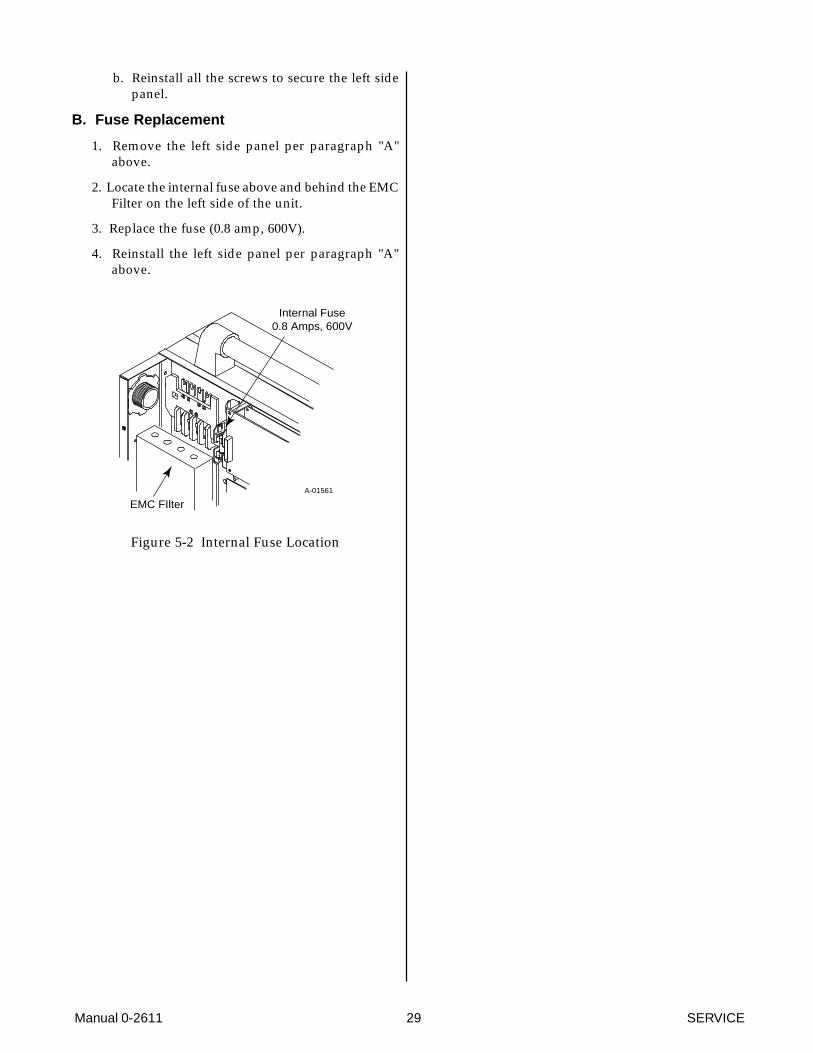
B. Fuse Replacement
1. Remove the left side panel per paragraph "A"above.
2. Locate the internal fuse above and behind the EMCFilter on the left side of the unit.
3. Replace the fuse (0.8 amp, 600V).
4. Reinstall the left side panel per paragraph "A"above.
A-01561
Internal Fuse0.8 Amps, 600V
EMC FIlter
Figure 5-2 Internal Fuse Location

SERVICE 30 Manual 0-2611
Manual 0-2611 31 PARTS LISTS
SECTION 6:PARTS LISTS
6.01 Introduction
A. Parts List Breakdown
The parts list provide a breakdown of all replaceablecomponents. The parts lists are arranged as follows:
Section 6.03 Complete Power Supply Replacement
Section 6.04 Options and Accessories
NOTE
Parts listed without item numbers are not shown,but may be ordered by the catalog number shown.
B. Returns
If a Thermal Dynamics product must be returned forservice, contact your Thermal Arc distributor. Materialsreturned to Thermal Dynamics without proper authori-zation will not be accepted.
6.02 Ordering Information
Order replacement parts by catalog number and com-plete description of the part or assembly, as listed in theparts list for each type item. Also include the model andserial number of the torch. Address all inquiries to yourauthorized Thermal Dynamics distributor.
PARTS LISTS 32 Manual 0-2611
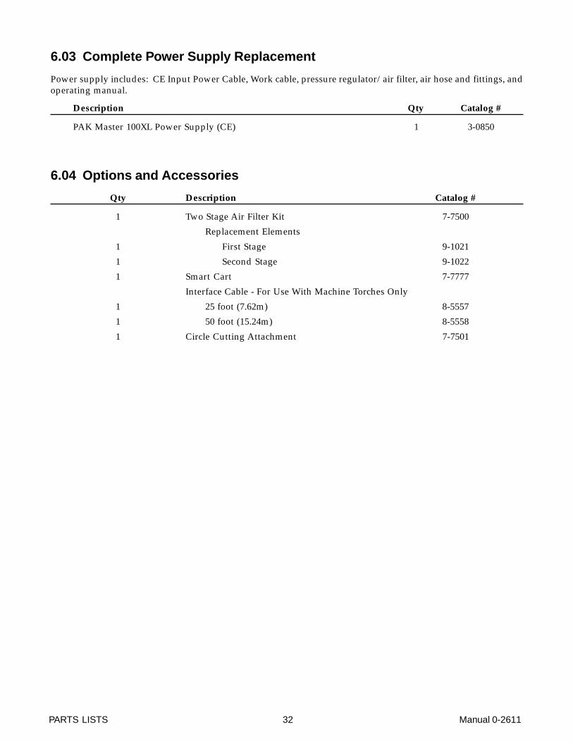
6.03 Complete Power Supply Replacement
Power supply includes: CE Input Power Cable, Work cable, pressure regulator/air filter, air hose and fittings, andoperating manual.
Description Qty Catalog #
PAK Master 100XL Power Supply (CE) 1 3-0850
6.04 Options and Accessories
Qty Description Catalog #
1 Two Stage Air Filter Kit 7-7500
Replacement Elements
1 First Stage 9-1021
1 Second Stage 9-1022
1 Smart Cart 7-7777
Interface Cable - For Use With Machine Torches Only
1 25 foot (7.62m) 8-5557
1 50 foot (15.24m) 8-5558
1 Circle Cutting Attachment 7-7501

Manual 0-2611 33 APPENDIX
APPENDIX I: INPUT WIRING REQUIREMENTS
In p u t P ow er In p u t C ur r en t S ug g ested S iz es (S ee N o tes)
V o ltag e F r eq . 3-P h 3-P h F u se (Am p s) W ir e (m m 2)
(V o lts) (Hz ) (kV A ) (Am p s) 3-P h 3-P h208 50/60 12.8 35.6 45 10230 50/60 13.2 33.2 40 10240 50/60 12.8 30.7 35 10380 50/60 14.2 21.5 25 10415 50/60 14.2 19.8 25 10
460 50/60 15.2 19.1 25 10
Line V oltages w ith S ugges ted C irc ui t P rotec tion and W ire S iz es
NOTES
Refer to Local and National Codes or local authority having jurisdiction for proper wiring requirements.
Cable size is de-rated based on the Duty Cycle of the equipment.
The suggested sizes are based on flexible power cable with power plug installations. For hard-wired installationsrefer to local or national codes.
Cable conductor temperature used is 167° F (75° C).
An energy limiting fuse UL Class RK-1 (examples: BUSS LPS/LPN-RK or Gould-Shawmut AZK-A6K) shouldbe used to minimize damage to Plasma Cutting, Welding or power distribution equipment.
NEVER use replaceable element fuses like UL Class H, or "one-time" fuses like UL Class K5.

APPENDIX 34 Manual 0-2611
APPENDIX II: SEQUENCE OF OPERATION(BLOCK DIAGRAM)
ACTION
ON/OFF switchto OFF
RESULT
All indicators off.Power supply fans off.
ACTION
RUN/SET switch to RUN.
RESULT
Gas flow stops. GAS indicator off.
ACTION
Torch moved within transfer distance of workpiece.
RESULT
Main arc transfer.Pilot arc off.
ACTION
Torch deactivated (by torch switch release or by remote device).
RESULT
Main arc stops.(Power supply enable signal removed.)
Gas flows (15 seconds)
NOTE - If torch is activated duringpost-flow, pilot arc will immediately restart. If torch is within transfer distance (3/8 in) of
workpiece, main arc will transfer.
After post-flow:
Gas solenoid closes, gas flow stops. GAS indicator off.
ACTION
Open external disconnect.
RESULT
No power to system.
ACTION
Close externaldisconnect switch.
RESULT
Power to system.
ACTION
RUN/SET switch to SET.
RESULT
Gas solenoid open, gas flows to set pressure.
GAS indicator on.
ACTION
Torch moved away from work (while
still activated).
RESULT
Main arc stops.Pilot arc automatically
restarts.PILOT ARC
ACTION
ON/OFF switchto ON.
RESULT
AC indicator blinks for 8seconds then steady on.
Fans on. Power circuit ready.
ACTION
Protect eyes and activate torch
RESULT
Gas flows (2 seconds).
After gas pre-flow:
DC indicator on. Pilot relay closes.
Pilot arc established
A-00926

Manual 0-2611 35 APPENDIX
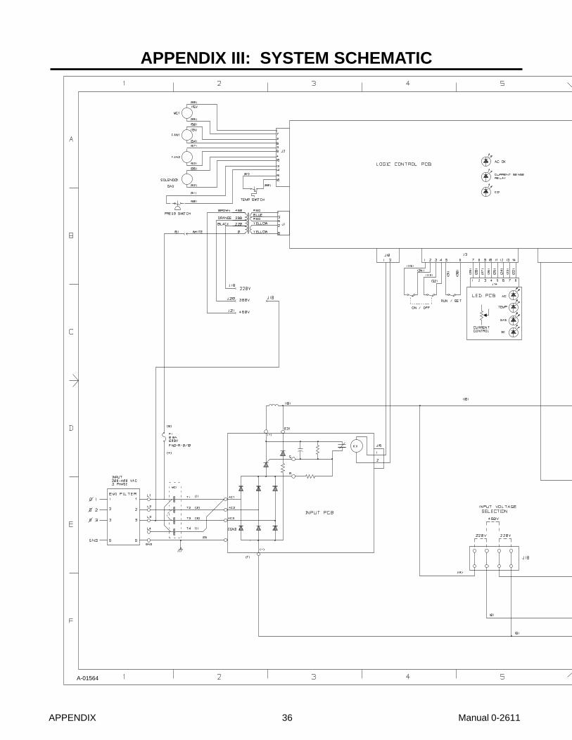
APPENDIX 36 Manual 0-2611
APPENDIX III: SYSTEM SCHEMATIC
A-01564
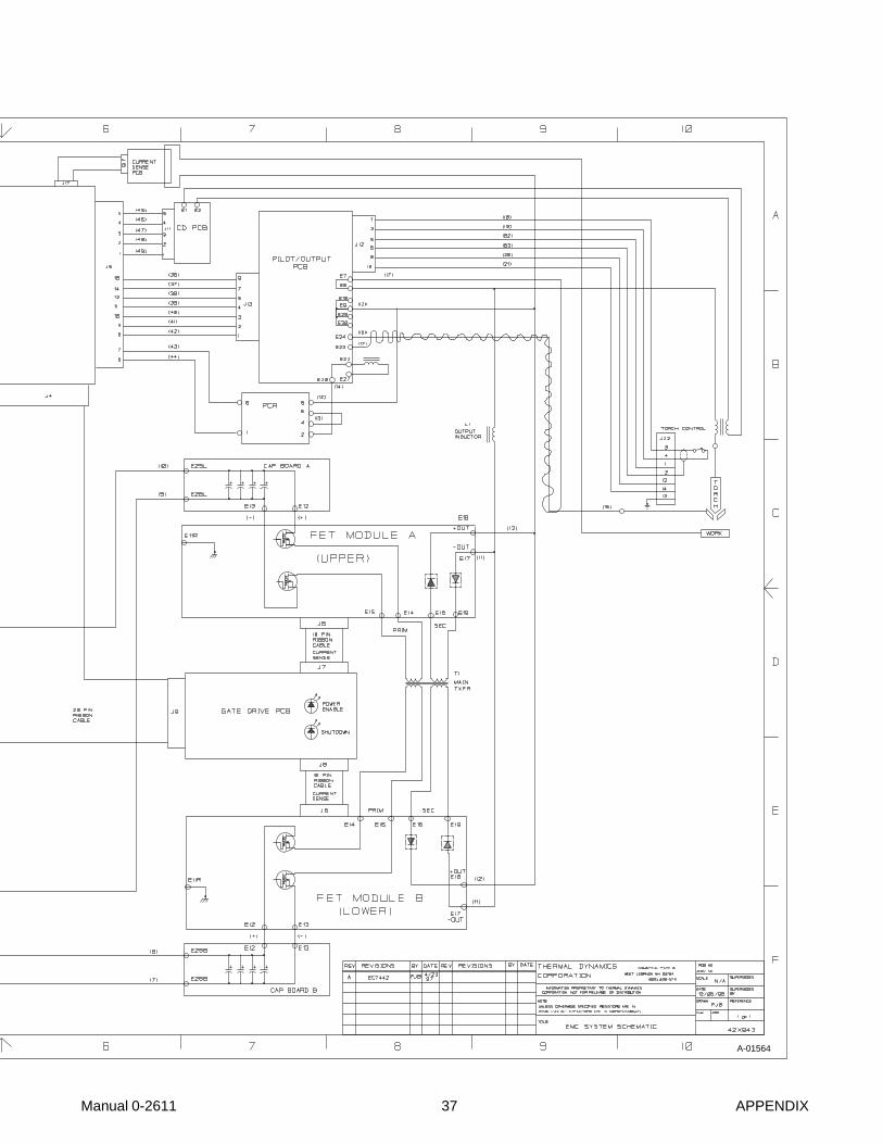
Manual 0-2611 37 APPENDIX
A-01564