Embed Size (px)
Citation preview
OEC FlexiView 8800™
Mobile C-Arm
Operator's Guide
Part Number 00-884008-01
GE Medical SystemsOEC
Page ii
Contents
Text Manual Revision History
Rev Dash Date Change DescriptionA -01 Dec, 2001 First release
Copyright© August 2001
GE Medical Systems
CAUTION!US Federal law restricts this device to sale by,
or on the order of, a physician.
The text of this manual was originally written, approved andpublished by the manufacturer in English (P/N 884008-01).
This manual may not be reproduced, in whole or in part, without the writtenpermission of GE Medical Systems .
The material in this manual is provided for informational purposes only andis subject to change without notice.
This product is covered under one or more of the following U.S. and foreignpatents: 5,596,228; 08/209,001; 5,426,683; 5,506,882; 5,583,909;
4,797,907; 07/638,176. Other U.S. and foreign patents pending. Made in theU.S.A.
B -01 Feb, 2002 Addition of Labels for Germany C -01 Apr, 2002 X-Ray Tube specification changes

Page iii
Contents
Table of ContentsIntroduction and Safety ............................................ 1-1
Overview .......................................................................................................................... 1-1Owner Responsibilities .................................................................................................... 1-2
System Compatibility ................................................................................................ 1-3Operator Qualifications ............................................................................................. 1-3Continued Compliance .............................................................................................. 1-3Unauthorized Modifications ..................................................................................... 1-3
GE Medical Systems ........................................................................................................ 1-4System Certification ...................................................................................................... 1-4X-ray Source Assembly Certification ....................................................................... 1-4After-sale Operating and Safety Practices ................................................................ 1-4
Communication Center Telephone Numbers .................................................................... 1-5Safety Hazards .................................................................................................................1-10Safety Hazard Alerts...................................................................................1-10
Burns .......................................................................................................................1-11Non -anesthetic Proof(Explosion)............................................................1-12Collision................................................................................................1-13Motorized Mechanical Movement ...........................................................................1-14Improperly Attached Equipment ..............................................................................1-14Electrical Shock ........................................................................................................1-15Electrical Fire ............................................................................................................1-17Recycling ............................................................................................................................. 1-18Packing Materials ............................................................................................................... 1-18Radiation Exposure .................................................................................................. 1-19
General Protection ............................................................................................ 1-19Source-to-Skin Distance ...................................................................................1-20
Ingress of Fluids ......................................................................................................1-21Equipment Malfunction ...........................................................................................1-21External Devices ......................................................................................................1-22Patient Environment ................................................................................................1-23
Within United States.......................................................................1-23
Outside United States.....................................................................1-24

Page iv
Contents
Start-up and Storage ................................................. 2-1
Overview .......................................................................................................................... 2-1Power On ......................................................................................................................... 2-2Draping ............................................................................................................................ 2-7Standby or Power Off ....................................................................................................... 2-8
Standby ................................................................................................................................. 2-8Power Off ......................................................................................................................... 2-9Storing the C-arm ............................................................................................................2-10
Temporary Storage (less than 60 days) ....................................................................2-10Long Term Storage or Shipment (60 days or more) ..................................................2-10
Operating Controls ................................................... 3-1
Overview .......................................................................................................................... 3-1Control Panel Housing ..................................................................................................... 3-2
Control Panel ............................................................................................................ 3-3Image Orientation .............................................................................................. 3-4Remote Workstation Operation ......................................................................... 3-5Image Intensifier Field Size ................................................................................ 3-7Collimator Control .............................................................................................. 3-8Contrast/Brightness .........................................................................................3-10Generator Control .............................................................................................3-12
Fast Stop Switches ..................................................................................................3-17X-ray On Switch ...................................................................................................... 3-19
Footswitch and Handswitch ..........................................................................................3-20
Page v
Contents
Mechanical Positioning.............................................. 4-1
Overview .......................................................................................................................... 4-1C-arm Identification .......................................................................................................... 4-2Component Identification ................................................................................................ 4-3
C-arms with 9 inch Image Intensifiers ....................................................................... 4-3Positioning ....................................................................................................................... 4-5
C-arm Orbital Rotation .............................................................................................. 4-5C-arm Orbital Rotation Brake .................................................................................... 4-6C-arm Yoke Rotation ................................................................................................. 4-7C-arm Yoke Brake.................................................................................................................4-8Vertical Column Operation ........................................................................................ 4-9Vertical Column Switches .........................................................................................4-10Horizontal Cross-arm ...............................................................................................4-11Horizontal Cross-arm Brake .....................................................................................4-12Wig-Wag ..................................................................................................................4-13Wig-Wag Brake ........................................................................................................ 4-148800 C-Arm Wheel Brakes .......................................................................................4-158800 C-Arm Steering Handle ....................................................................................4-16
Moving the C-arm ...........................................................................................................4-17

Page vi
Contents
Radiographic Film ..................................................... 5-1
Overview .......................................................................................................................... 5-1Setup and Make a Film Exposure ..................................................................................... 5-2Prearm for Film Exposure .................................................................................................. 5-6
Maintenance .............................................................. 6-1
Overview .......................................................................................................................... 6-1Performance Checks ......................................................................................................... 6-3
Mechanical Performance Check ................................................................................ 6-3Electrical Performance Check .................................................................................... 6-4Fast Stop Performance Check ................................................................................... 6-5Fluoro Mode Performance Check ............................................................................. 6-6Film Mode Performance Check ................................................................................. 6-7
Cleaning ........................................................................................................................... 6-8Periodic Maintenance ......................................................................................................6-9
Display Messages........................................................7-1
Overview .......................................................................................................................... 7-1Error Recovery Steps ....................................................................................................... 7-2Messages ......................................................................................................................... 7-3
Labels and Symbols ................................................. 8-1
Overview .......................................................................................................................... 8-1Labels ............................................................................................................................... 8-2Symbols ........................................................................................................................... 8-4
Page vii
Contents
Technical Reference ................................................. 9-1
Overview .......................................................................................................................... 9-1Classification Type .......................................................................................................... 9-2Electromagnetic Compatibility Statement ......................................................................... 9-2Optional equipment.......................................................................................9-3Replacement Items.......................................................................................9-3Camera Output Video Signal..........................................................................9-4Environmental Requirements ........................................................................................... 9-4C-arm Power Requirements .............................................................................................. 9-5X-ray Source Assembly ................................................................................................... 9-5
Collimation ................................................................................................................ 9-7Tube Rating Charts ........................................................................................ 9-8
Filament Emission Characteristics.......................................................... 9-8Single Load Rating - Small Focus........................................................... 9-9Single Load rating - Large Focus........................................................ 9-10Heating and Cooling Charts-Anode ...................................................... 9-11
Generator Specifications ................................................................................... 9-12Generator Operating Parameters ..............................................................................9-13Measurement Basis for Technique Factors .............................................................9-14Radiographic mA
As a Function of kV and mAs ..........................................................................9-14Focal Spot (0.6 x 1.4 mm) ..........................................................................................9-15Focal Spot (1.4 mm) ..................................................................................................9-16
Dimensions .....................................................................................................................9-17C-arm (9-inch II) .......................................................................................................9-17
Film Cassette Dimensions ...............................................................................................9-17Material Safety Data Sheets ............................................................................................9-18
Chapter 1
Page 1-1
Introduction and Safety
OverviewThis guide describes FlexiView8800 Mobile C-arm operation only. It isdesigned to provide fluoroscopic and spot film imaging of the patient duringdiagnostic and surgical procedures. It is intended for qualified medicalpersonnel who have been trained in the use of medical imaging equipment.It is not designed to replace or substitute for certified training in theradiological or medical field.
Functional capabilities and operation of the equipment are described herewhich can be used in a variety of diagnostic, therapeutic and surgicalapplications.
The Mobile C-arm's dependency on the workstation for power and imageprocessing requires that setup and basic interaction between these componentsbe included here. Complete Workstation operating instructions are containedin the 1k x 1k Workstation Operator's Guide.
Page 1-2
Introduction and Safety
Owner ResponsibilitiesThe owner has the responsibility to ensure system compatibility, operatorqualifications and the continued compliance of equipment and operatingspecifications. Systems should only be used in designated use areas withapproved AC receptacles. Unauthorized changes or modifications to anypart of the system could have hazardous consequences. Changes ormodifications must not be made unless specifically authorized by GE MedicalSystems.
This Product complies with theregulatory requirements of the following:
Council Directive 93/42/EEC concerning medical device:
For a system, the location of the CE marking label is described in theSystem Manual.
i) For the Product with CE 0459 label affixed and manufactured inWendelstein, Germany, the European registered place of business:OEC Medical System GmbHWilhelm Maisel Str.1490530 WENDELSTEIN Germany.
ii) For the Product with CE 0459 label affixed and manufactured inBangalore, India, the European registered place of business:GE Medical Systems EuropeQuality Assurance ManagerBP 34F 78533 BUC CEDEX FranceTel:+33 (0)1 30 70 40 40.
Page 1-3
Introduction and Safety
System CompatibilityThe Flexi View 8800 Mobile C-arm should only be used in conjugation witha 1k x 1k Workstation. The FlexiView 8800 is not compatible withWorkstations sold as part of a 9600 and 9800 system. Damage mayresult to the system if incompatible components are connected.
Operator QualificationsIt is the responsibility of the owner to ensure that the system is operated onlyby properly trained, qualified personnel who have obtained credentials fromthe appropriate authorities.
Continued ComplianceThe owner is responsible for verifying continued compliance with allapplicable regulations and standards. Consult local, state, federal and/orinternational agencies regarding specific requirements and regulationsapplicable to the use of this type of medical electronic equipment.
Unauthorized ModificationsWhen properly assembled with a compatible beam limiting device, the X-raysource assembly fully meets US Federal regulations and Internationalstandards, provided no components or parts are removed from the unit andno unauthorized adjustment is made in the beam limiting device or tubehousing assembly. Never remove any part of the housing or beam limitingdevice . Never adjust any part of the beam limiting device unless directed byqualified GE Medical Systems personnel.
Page 1-4
Introduction and Safety
GE Medical Systems ResponsibilitiesGE Medical Systems certifies each system and X-ray source assembly.After-sale operating practices and safety are the responsibility of the owner/operator.
System CertificationGE Medical Systems certifies that each system complies with the USFederal regulations and International standard applicable to diagnosticequipment.
X-Ray source Assembly CertificationIn accordance with 21 CFR 1020, GE Medical Systems certifies that thecomponents contained in the X-ray source assembly, when assembledaccording to manufacturer's instructions, are compatible for use with theFlexiView8800.
The use of any X-ray tube or beam-limiting device not authorized by GEMedical Systems may affect compliance with standards and regulationsapplicable to X-ray source assemblies.
After-sale Operating and Safety PracticesGE Medical Systems assumes no responsibility or liability for after-saleoperating and safety practices; nor can it be responsible for personal injuryor damage resulting from misuse of its systems.

Page 1-5
Introduction and Safety
Communication CenterTelephone Numbers
If the system does not operate properly or fails to respond to the controls asdescribed in your operator’s manual, call GE OEC Medical Systems, Inc. torequest service. The communication center's telephone numbers are listedbelow:
Service OfficesFor service issues, contact the Service Office for your Country.
AMERICAS
UNITED STATES OF AMERICAGE Medical Systems OEC Headquarters Tel: +1-801-321-9300384, Wright Brothers Drive. Fax: +1-414-544-3384Salt Lake City, Ut 84116
GE Medical SystemsMilwaukee, U.S.A.
LATIN AMERICA
GE Medical Systems Tel: +1-305-497-1200Latin America Headquarters5101 NW 21st Avenue, Suite 350FORT LAUDERDALE, FL 33309 USA

Page 1-6
Introduction and Safety
ASIA
(Japan)
GE Yokogawa Medical Systems, Ltd Tel :81-42-585-55004-7-127 Asahigaoka 4-chome, Hino-shi, Fax: 81-42-585-5470Tokyo, 191-8503 JAPAN
(Singapore)
GE Pacific Pte Ltd Tel: 65-291-8528298 Tiong Bahru Road #15-01/06 Fax: 65-275-9424Central Plaza, Singapore 168730
(China)
GE (China)Co. Ltd., Medical Systems Tel: 86-10-6506-00886F, North Tower , Grand Pacific Building Fax: 8610-6581-61018A Guanghua Road, Chao Yang DistrictBeijing, PR China - 100026
(Korea)
Samsung GE Medical Systems Tel:82-342-740 604665-1 Sangdaewan-Dong Fax:82-342-740 6431Chungwon-ku, Sungnam-SiKyunggi-Do, Korea 462 120
(India)
Wipro GE Medical Systems Ltd. Tel:91-80-845 29234 Kadugodi Industrial Area Fax:91-80-845 2924Bangalore 560 067, India
Page 1-7
Introduction and Safety
EUROPE
DANMARK (Denmark)
GE Medical Systems Danmark Tel: +45 45 51 00 55Skovlytoften 4 Fax: +45 42 42 59 89DK – 2840 HOLTE
DEUTSCHLAND (Germany)
GE Medical Systems Deutschland Tel: 49-6102-36-0GmbH & Co. KG Fax:+49610–36–2588Martin – Behaim – Strasse 10D – 63263 NEU ISENBURGS
ESPANA (Spain)
GE Medical Systems Espana TeI: +34 1 663 25 00Avda. de Europa 22 Fax: +34 1 663 25 01Parque Empresarial la MoralejaE – 28100 ALCOBENDAS
FRANCE (France)
GE Medical Systems Tel:+33 (0)1307040 40283 rue de la MiniereBP34F – 78533 BUC CEDEX
HELLAS (Greece)
GE Medical Systems Hellas Tel: +30 1 93 24 58241 Nikolaou Plastira Street Fax: +30 1 93 58 414GR – 171 21 NEA SMYRNI
Page 1-8
Introduction and Safety
ITALIA (Italy)
GE Medical Systems Italia Tel: +39 02 64 22 01Viale Fulvio Testi 28 – B Fax: +39 02 64 22 040120126 MILANO
NEDERLAND (Netherlands)
GE Medical Systems Nederland B.V. Tel: +31 73 6 457 457Hambakenwetering 1 Fax: +31 73 6 441 233NL – 5231 DD S HERTOGENBOSCH
OSTERREICH (Austria)
GE GesmbH Medical Systems Austria Tel: 0660 8651Prinz Eugen Strasse 8/8 Fax: +43 1 505 38 74A – 1140 WIEN Tlx: 136314
POLSKA (Poland)
GE Medical Systems Polska Tel: +48 2 625 59 62Krzywickiego 34 Fax: +48 2 615 59 66P – 02 – 078 WARSZAWA
PORTUGAL (Portugal)
GE Medical Systems Portuguesa S.A. Tel: +3512 2007696/97Rua Sa da Bandeira, 585 Fax: +351 2 2084494Apartado 4094 Tlx: 22804P-4002 PORTO CODEX Tel (satellite): +7 502 220 30 39
Fax (satellite): +7 502 220 32 59

Page 1-9
Introduction and Safety
SVERIGE (Sweden)
GE Medical Systems Tel: +46 8 457 95 20Box 6768 Fax: +46 8 457 95 47St. Eriksgatan 117 Tlx: 12228 CGRSWESS-113 85 STOCKHOLM
SCHWEIZ/SUISSE (Switzerland)
GE Medical Systems (Schweiz) AG Tel: 155 6958Sternmattweg 1 Fax: +41 41 421859CH – 6010 KRIENS Fax: +41 41 421859
TURKIYE (Turkey)
GE Medical Systems Turkiye A.S. Tel: +90 212 75 5552Mevluk Pehliran Sodak Fax: +90 212 211 2571Yilmaz Han, No 24 Kat 1GayretteppeISTANBUL
UNITED KINGDOM
IGE Medical Systems Tel: +44 753 874000Coolidge House Fax: +44 753 696067352 Buckingham AvenueSLOUGHBerkshire SL1 4ER
Page 1-10
Introduction and Safety
Safety HazardsPotential hazards exist in the use of medical electronic devices and X-raysystems. Operators using the equipment should understand the safety issues,emergency procedures and the operating instructions provided.
Safety Hazard AlertsThe following pages describe hazardous and potentially hazardous conditions,and how to adequately protect yourself and others from possible injury.
There are three hazard classifications, which are denoted and prioritized bythe alert words:
1. Danger
2. Warning
3. Caution
This list describes the use of each classification:
Alert Circumstances for Use
DANGER Danger indicates an imminently hazardous situationwhich, if not avoided, will result in death or seriousinjury.
WARNING Warning indicates a potentially hazardous situationwhich, if not avoided, could result in death or seriousinjury.
Page 1-11
Introduction and Safety
CAUTION Caution indicates a potentially hazardous situationwhich, if not avoided, may result in moderate tominor injury, equipment damage or loss of data.
BurnsContinuous Fluoro exposure, overtime, especially HLF may cause componentssuch as X-ray tubes housing to reach temperatures capable of inflictingburns.Do not touch the housing or place the X-ray housing near patients.Warning messages are displayed on the C-arm's Control Panel Displayregarding the X-ray tube housing's temperature. Refer to the Chapter onDisplay Messages for more information.
CAUTION
Placing a hot X-ray tube housing in close proximity to humananatomy could result in serious burns.
NOTE: When the X-Ray tube housing is draped, heat will not dissipateas efficiently.

Page 1-12
Introduction and Safety
Non-anesthetic Proof (Explosion)Vapors and gases can be ignited by electrical arcs that can occur during thenormal operation of switches, circuit breakers, push buttons and other circuitcomponents.
The system must never be operated in the presence of flammable anestheticor other flammable or explosive liquids, vapors, or gases. If flammablesubstances are detected after the system has been energized:
1. Do not turn the system off or unplug it from the AC receptacle.
2. Do not operate any other electrically powered equipment.
3. Evacuate all personnel from the area and ventilate with fresh air.Avoid operating any automated (electrically operated) doors orwindows.
4. Contact your local fire department as soon as possible.

Page 1-13
Introduction and Safety
CollisionIf your system is mounted on wheels and casters and it is moved or operatedimproperly, it could roll out of control. Follow these guidelines:
• Two people should maintain control of the equipment when movingup or down an incline.
• Place all mechanical assemblies in their most compact (transport)position and lock brake handles prior to moving the equipment.
• Use the handles designed for moving the equipment and mechanicalassemblies.
• Never attempt to move the system up or down steps or on an inclinegreater than 10 degrees. System can be moved at 10 degrees inclineonly in Transport position.
• Do not operate the C-arm equipped with a 9-inch image intensifieron inclines greater than 10 degree.
• Do not lock the wheel brakes and leave the equipment unattendedon unlevel floors.
• Always apply the wheel locks when the system is in its final position.
• Do not move the equipment if the castors or wheels are notfunctioning properly.
• Mechanical shocks to the equipment while disk drives are accessinginformation may cause damage to the disk drive.

Page 1-14
Introduction and Safety
Motorized Mechanical MovementThe Vertical column assembly is motorised and may cause injury if operatedimproperly.
Observe the vertical Column closely when operating the motor to avoidcollision with a person or object.
Improperly Installed Film Cassette HolderIf your equipment accommodates a film cassette holder or some other pieceof equipment and is not properly installed, it could fall, causing injury to patientor operator. Use only equipment supplied by GE Medical Systems. Verifythat the cassette holder is correctly installed.
Note: Refer to the Chapter on Radiographic Film Mode for instructions oninstalling the film cassette holder.
Incorrect Film Cassette size
A film cassette with incorrect dimensions may not fit in the cassette holderproperly.
Only use film cassettes that are the correct size. Refer to the chapter onTechnical reference for film cassette dimensions.

Page 1-15
Introduction and Safety
Electrical ShockObserve the following safety procedures to avoid electric shock or seriousinjury to operators and patients and to avoid system malfunction:
• Make all electrical connections to equipment while outside thepatient environment. Do not touch a connector and the patient at thesame time.
• Do not bypass jumper or otherwise disable the safety interlocks.
• Do not remove any of the assembly covers. Only trained servicerepresentatives should perform repairs.
• Do not place food or beverage containers on any part of theequipment. If spilled, they can cause short circuits.
• Always remove power to the equipment before cleaning. Use aslightly damp cloth or sponge for cleaning.
• Only qualified service engineers are allowed to service or repair asystem.

Page 1-16
Introduction and Safety
WARNING
The Mobile C-arm is not waterproof. Water, soap or otherliquids, if allowed to drip into the equipment, can causeelectrical short circuits leading to electric shock and fire
hazards. If liquids should accidently spill into the system, donot apply power or turn the system on until the liquids have
dried or evaporated completely.
Certain components within the system produces high voltages whichcan be potentially hazardous. To avoid this hazard, only qualifiedservice engineers are allowed to service or repair a system.
WARNING
Electrical circuits inside the equipment may use voltageswhich are capable of causing serious injury or
death from electric shock. To avoid this hazard,never remove any of the cabinet covers.

Page 1-17
Introduction and Safety
Electrical FireIn the event of electrical fire perform the following emergency procedure:
NOTE: Any emergency procedure developed by the owner, for the area inwhich the system is used, should include these safety measures:
• Remove electrical power to the system by placing the power switchin the off position.
• Unplug the power cord from the AC receptacle.
• Evacuate personnel from the area.
• Only use a fire extinguisher that is approved for use on electricalfires.
• Call your local fire department for help if necessary.
WARNINGThe use of the wrong type of fire extinguisher presents
electrical shock and burn hazards. To avoid these hazards, afire extinguisher which meets applicable regulations and
standards must be available in the room where the equipmentis being used. Remember that equipment that is equipped withbatteries is a source of electrical current, even when AC power
is disconnected.
Page 1-18
Introduction and Safety
RecyclingMachines or accessories at end of life:The elimination of machines and accessories must be in accordance withnational regulations for waste processing.
All materials and components that could pose a risk to the environment mustbe removed from the end of life machines and accessories (examples : dryand wet cell batteries, transformer oil, consumables, etc.)
Please consult your local GE Medical Systems representatives beforediscarding these products.
Packing MaterialsThe materials used to pack our rquipment are recyclable. They must becollected and processed in accordance with the regulations in force for thecountry where the machines or accessories are unpacked.

Page 1-19
Introduction and Safety
Radiation ExposureGeneral Protection
WARNINGThis equipment either produces or is used in
the vicinity of ionizing radiation. Observe propersafety practices during operation.
• The owner must designate areas suitable for safe operation andservice of the equipment and ensure that they are only used in thesedesignated areas. It is the responsibility of the owner to ensure thatall personnel wear appropriate protective clothing and radiationmonitoring devices while using the equipment.
• A visual indicator on top of the workstation is provided to alert youthat an X-ray switch has been actuated and the X-Ray tube isgenerating ionizing radiation. An audible alarm can also be configuredto sound if you desire one.Contact your field service representativeto turn on the fluoro alarm.
NOTE: Refer to your Workstation Operator's Guide for information aboutadjusting the frequency (pitch) of the alarm through menus on theworkstation.

Page 1-20
Introduction and Safety
Source-to-Skin DistanceInternational regulations specify that a minimum source-skin distance shallbe maintained at 30 cm, except for specific surgical applications. In theseapplications, provisions have been made to allow for operation at 20 cm. Byremoving the skin spacer from the collimator assembly, the minimum sourceto skin distance can be altered from 30 cm to 20 cm.
WARNINGRemoving the skin spacer may result in increased
radiation exposure to the patient.
The skin spacer should only be removed on the instructions of a physician.The spacer should be reattached to the collimator assembly immediatelyfollowing the procedure.

Page 1-21
Introduction and Safety
Ingress of FluidsExcessive amounts of fluids such as antiseptics, cleaning solutions or bodyfluids may damage internal components, if they are allowed inside theequipment. Use drapes, if necessary, to protect equipment when performingprocedures and do not apply excessive amounts of fluid when cleaning.
Equipment MalfunctionIf either the hospital or equipment circuit breakers trip, an equipmentmalfunction may be indicated. Do not attempt to operate the equipment untilit has been checked by a qualified service engineer.
If any of the equipment controls fail to respond as indicated in this manual,you should:
1. Remove power to the equipment by placing the power switch in theoff position and unplugging the power cord from the AC receptacle.
2. Notify a qualified service engineer.
3. Do not operate the equipment until the service technician advises thatit is operating properly.

Page 1-22
Introduction and Safety
External DevicesTo ensure patient safety, only connect external equipment that has beenapproved by GE Medical Systems. All equipment attached to the externalinterface connections must meet the requirements of IEC 60601-1 whenoperated within the patient environment. When used outside of the patientenvironment, each externally connected device must comply with therelevant IEC/ISO requirements for that device. In any case, the combinationof all externally connected equipment shall not cause the leakage current ofany device used within the patient environment to exceed the limits stated inIEC 60601-1.
Page 1-23
Introduction and Safety
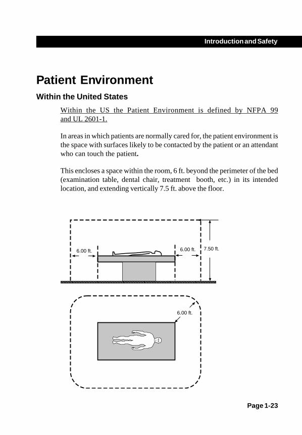
Patient EnvironmentWithin the United States
Within the US the Patient Environment is defined by NFPA 99and UL 2601-1.
In areas in which patients are normally cared for, the patient environment isthe space with surfaces likely to be contacted by the patient or an attendantwho can touch the patient.
This encloses a space within the room, 6 ft. beyond the perimeter of the bed(examination table, dental chair, treatment booth, etc.) in its intendedlocation, and extending vertically 7.5 ft. above the floor.
6.00 ft. 7.50 ft.6.00 ft.
6.00 ft.
Page 1-24
Introduction and Safety
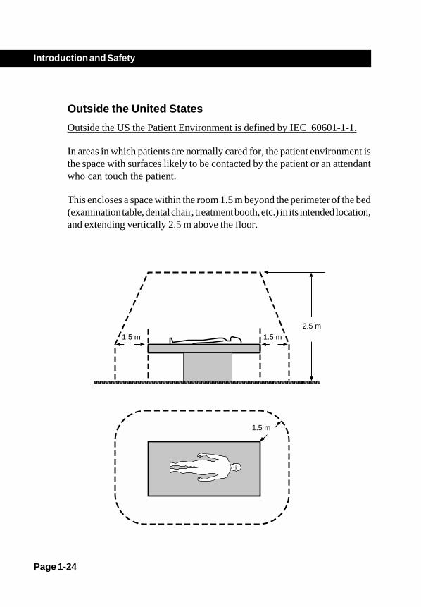
Outside the United States
Outside the US the Patient Environment is defined by IEC 60601-1-1.
In areas in which patients are normally cared for, the patient environment isthe space with surfaces likely to be contacted by the patient or an attendantwho can touch the patient.
This encloses a space within the room 1.5 m beyond the perimeter of the bed(examination table, dental chair, treatment booth, etc.) in its intended location,and extending vertically 2.5 m above the floor.
1.5 m
2.5 m
1.5 m
1.5 m

Start-up and Storage
OverviewThis chapter describes:
• Applying power• Removing power• Storing the C-arm
Chapter 2
Page 2-1
Page 2-2
Start-up and Storage
Power ONIf you are starting the system after a period of long term storage it may benecessary to allow the system to warm up or recharge the batteries beforeit can be used. The system clock will sense how long the system has beenin storage and display a message that describes the action required. Refer tothe "Display Messages" chapter for more information.
The Mobile C-arm receives power through an interconnect cable attachedto the Workstation. The C-arm must be connected to the Workstation andelectrical power before operation. Refer to the 1k x1k Workstation Operator'sGuide for additional information.
CAUTIONIf the connector does not lock in place, unreliable system
operation may result.

Page 2-3
Start-up and Storage
1. Insert the Workstation interconnect cable into the connector located onthe right side cover of the C-arm by aligning the index marks (red dots)on the connector and pushing the connector in until it locks in place.
CAUTION
Damage may result to the C-arm if the interconnectcable is inserted after the workstation power
cord is plugged into an AC receptacle.
22222.
Figure 2.1. Connect the C-arm to the Workstation

Page 2-4
Start-up and Storage
Connect the footswitch and/or handswitch to the sockets on the C-arminterface panel located on the left side cover. Verify that each connectorlocks in place.
- +
A
B
C
D
Figure 2-2. C-arm interface panel.
A When the keyswitch is placed in the on position (clockwise;horizontal) the C-arm is fully operational. When the keyswitch isplaced in the standby position (counter-clockwise; vertical) X-raysand vertical column movement are disabled, but the C-arm remainspowered.
B Battery charger indicator lamp illuminates when the batteries arecharging.
C Handswitch connector socket.
D Footswitch connector socket.

Page 2-5
Start-up and Storage
3. Plug the Workstation power plug into a properly rated AC receptacle.Refer to the OEC Workstation Operator Manual for informationabout power requirements.
NOTE: Once the Workstation power cable has been plugged into an ACreceptacle, the battery charger indicator on the C-arm interface panelwill illuminate indicating that the batteries are charging.
4. Turn the key switch located on the C-arm interface panel clockwise toenable X-rays and motorized mechanical movement.
5. Press the Workstation power switch. The light within the switch will turnon indicating the power is turned on. Both the Workstation and the C-armwill begin their power up sequence.
Figure 2-3. Power on the system.
NOTE: The C-arm control panel will display a sequence of lighted segmentsindicating that it is proceeding with the power up sequence.
Page 2-6
Start-up and Storage
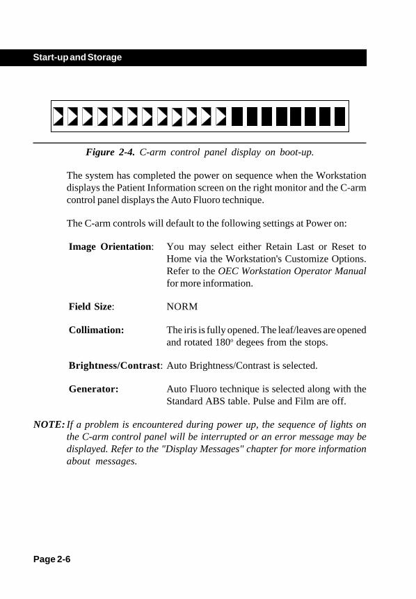
Figure 2-4. C-arm control panel display on boot-up.
The system has completed the power on sequence when the Workstationdisplays the Patient Information screen on the right monitor and the C-armcontrol panel displays the Auto Fluoro technique.
The C-arm controls will default to the following settings at Power on:
Image Orientation: You may select either Retain Last or Reset toHome via the Workstation's Customize Options.Refer to the OEC Workstation Operator Manualfor more information.
Field Size: NORM
Collimation: The iris is fully opened. The leaf/leaves are openedand rotated 180o degees from the stops.
Brightness/Contrast: Auto Brightness/Contrast is selected.
Generator: Auto Fluoro technique is selected along with theStandard ABS table. Pulse and Film are off.
NOTE: If a problem is encountered during power up, the sequence of lights onthe C-arm control panel will be interrupted or an error message may bedisplayed. Refer to the "Display Messages" chapter for more informationabout messages.
Page 2-7
Start-up and Storage
DrapingIf you are performing a procedure where draping is necessary, drape the C-arm using the SteriQuick draping system. The draping system can bepurchased from GE Medical Systems by contacting your sales representative.
NOTE: Use of a footswitch cover is recommended during all medical procedures.
Draping the X-ray tube housing will inhibit air flow resulting in coolinginefficiencies. This may result in the housing reaching its rated heat capacitysooner. You will receive messages indicating the temperature of the housing.When the housing reaches its maximum rated heat capacity, X-rays will bediscontinued until the housing has cooled. Refer to the "Display Messages"section for more information.
NOTE: Instructions for draping are contained in the drape packaging.

Page 2-8
Start-up and Storage
Standby or Power OFFPerform the following steps to place the C-arm in Standby or to completelyremove power.
Standby
1. Turn the C-arm keyswitch to the standby position (counter-clockwise;vertical).
NOTE: Placing the equipment in standby disables X-rays and vertical columnoperation so these features will not be activated unintentionally. Amessage will be visible on the control panel display indicating that thekeyswitch is in standby.
2. Turn the keyswitch back to the on position when you are ready to use theC-arm. The Workstation power switch will remain lit, indicating thesystem is still powered on.

Page 2-9
Start-up and Storage
Power OFF1. Place the Workstation power switch in the off position.
2. Unplug the Workstation power cord from the AC receptacle.
3. Disconnect the Workstation interconnect cable from the C-arm.
NOTE:Remove all power from the system before moving the system or if aproblem occurs which prevents normal operation. All power shouldalso be removed when periodic maintenance and cleaning is performed.
CAUTIONDo not disconnect the interconnect cable from the C-armbefore unplugging the worstation from the AC receptacle.Power is still being applied to the C-arm batteries via the
interconnect cable.
Page 2-10
Start-up and Storage
Storing the C-arm
Temporary Storage (less than 60 days)1. To prepare the C-arm for storage, move all mechanical assemblies into
their most compact position, set all locks and brakes and remove allpower. Store any accessories with the C-arm.
2. Cover the C-arm with a dust cover. Refer to the "Technical Reference"chapter for the range of environmental conditions in which the C-arm canbe safely stored.
Long Term Storage or Shipment (60 daysor more)
To prepare the C-arm for long term storage or shipment, observe thefollowing recommendations:
1. Move all mechanical assemblies into their most compact positions, set alllocks and brakes and remove all power.
2. Wrap the image intensifier, X-ray tube assembly, C-arm cable, and thecontrol panel housing with bubble wrap.
3. Pack all accessories such as cassette holders and store them with thesystem.
4. Cover the C-arm and accessories. Attach each to a solid supportiveshipping base and enclose in a protective container adequate forshipment or storage. Refer to the "Technical Reference" chapter for therange of environmental conditions in which the C-arm can be safelystored.

Chapter 3
Page 3-1
Operating Controls
OverviewThis chapter describes the C-arm operating controls. Before you beginimaging, familiarize yourself with the following controls:
• Control Panel Housing Controls• Footswitch• Handswitch

Page 3-2
Operating Controls
Control Panel HousingThe C-arm control panel, fast stop switches and X-ray on switch are alllocated on the C-arm control panel housing.
Item Description 1 Control panel display 2 Control panel 3 Fast Stop switches (one on each side) 4 X-ray on switch 5 Vertical column motor switches
NOTE: Instructions for using the vertical column motor switches are containedin the chapter titled "Mechanical Positioning."
1
2
3
45
Figure 3-1. Control locations on the control panel housing.
Page 3-3
Operating Controls
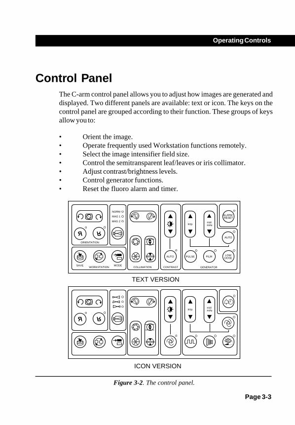
Control PanelThe C-arm control panel allows you to adjust how images are generated anddisplayed. Two different panels are available: text or icon. The keys on thecontrol panel are grouped according to their function. These groups of keysallow you to:
• Orient the image.• Operate frequently used Workstation functions remotely.• Select the image intensifier field size.• Control the semitransparent leaf/leaves or iris collimator.• Adjust contrast/brightness levels.• Control generator functions.• Reset the fluoro alarm and timer.
mA/mAskVp
mA/mAskVp
AUTO
LOWDOSEFILMPULSEAUTO
MODEWORKSTATION
SAVE
ORIENTATION
COLLIMATION
ALARM RESET
GENERATORCONTRAST
NORM
MAG 1
MAG 2
TEXT VERSION
ICON VERSION
Figure 3-2. The control panel.

Page 3-4
Operating Controls
Image OrientationUse these keys to rotate or reverse the image produced once X-rays havebeen generated and live video is present on the left Workstation monitor.
Image rotation and image reversal are not available to be used with cineplayback, on a recalled or swapped image, or when image annotation hasbeen applied. Rotation and reversal are best used with the most recent imageheld.
IMAGE ROTATION
Press the left portion of the key to rotate the image counter-clockwise. Press the right portion of the key to rotate the imageclockwise.
A camera icon will display and move to indicate which part of theimage will be rotated to the top. Once camera movement has ceased,the image will display rotated.
This feature is used with the most recent shot in order to aid settingoptimal camera orientation for the next live shot. The "last imagehold" is used for a source image while rotation and flip are applied.
IMAGE REVERSAL
Use these keys to change the orientation of the image displayed onthe Workstation's left monitor. Press the left key to reverse theimage from left to right. Press the right key to invert the image fromtop to bottom.

Page 3-5
Operating Controls
Remote Workstation Operation
SAVE
The save function can be used during a live X-ray or afterward tosave the last image displayed on the left monitor. While generatingX-rays, press the SAVE key to save one frame of the live X-ray tothe Workstation's hard-drive without interrupting live X-rays. Afteryou have completed the exposure, press the SAVE key to save thelast image displayed on the left monitor to the Workstation hard-drive.
SWAP
Use this function while generating live X-rays or after X-rays havebeen terminated.
While generating live X-rays - press the SWAP key to copy oneframe of the live X-ray and move it to the right monitor. PressingSWAP again will discard the previously swapped image and replaceit with the new image.

Page 3-6
Operating Controls
After X-rays have been terminated -the last frame of theexposure is retained on the left monitor (last image hold). Press theSWAP key to swap the images displayed on the left and rightmonitors.
If the right monitor is blank, press the SWAP key to copy the imageon the left monitor to the right monitor.
MODE
Use the MODE key to toggle between the standard fluoroscopymode and the vascular imaging mode when the C-arm is connectedto a Vascular Workstation.
On nonvascular systems an audible beep will sound to signify thatthis function is not available.
Page 3-7
Operating Controls
Image Intensifier Field Size
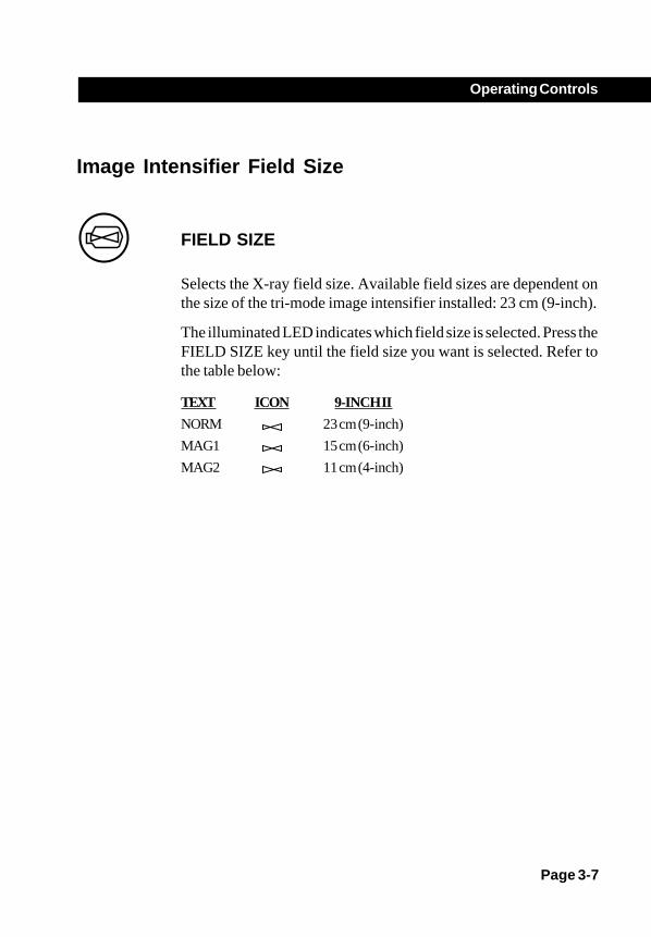
FIELD SIZE
Selects the X-ray field size. Available field sizes are dependent onthe size of the tri-mode image intensifier installed: 23 cm (9-inch).
The illuminated LED indicates which field size is selected. Press theFIELD SIZE key until the field size you want is selected. Refer tothe table below:
TEXT ICON 9-INCH II
NORM 23 cm (9-inch)
MAG1 15 cm (6-inch)
MAG2 11 cm (4-inch)

Page 3-8
Operating Controls
Collimator ControlThe X-ray beam may be collimated by using either the iris collimator or thesemitransparent leaf collimator. The collimator leaves and iris can bepositioned prior to generating X-rays. Press a collimator leaf or iris key anda graphic icon representing the position and orientation of the real collimatorleaves (two lines) or iris (circle) will be displayed on the left monitor.
NOTE: Your C-arm may be equipped with one or two semitransparent collimatorleaves. If your collimator has one leaf the graphic icon will display onlyone line instead of two.
Press the key until the leaves or iris are in the position you desire and thenpress any X-ray switch. An X-ray image, collimated according to the positionand orientation of the graphic icon, will be displayed on the left monitor. Thisfeature helps reduce exposure to X-rays while collimating.
COLLIMATOR LEAF ROTATION
Press the left portion of the key to rotate the collimator leaf/leavescounter-clockwise or the right portion to rotate the collimator leaf/leaves clockwise.

Page 3-9
Operating Controls
IRIS COLLIMATOR OPEN/CLOSE
Press the iris collimation key to open or close the collimator iris.Press the top portion of the key to open the iris or the bottom portionof the key to close the iris.
COLLIMATOR LEAF OPEN/CLOSE
Press the collimator leaf key to open and close the semitransparentcollimator leaf/leaves. Press the top portion of the key to open theleaf/leaves or press the bottom portion of the key to close the leaf/leaves.

Page 3-10
Operating Controls
Contrast/Brightness
MANUAL CONTRAST / BRIGHTNESS
Pressing this key changes control to manual contrast/brightnessmode and may be used to manually adjust contrast/brightness duringlive X-rays or during post-processing on the last image held.
You can increment or decrement through a series of contrast/brightness levels by pressing the top or bottom portion of the key. Avisual indicator is displayed on the monitor to help you adjust thecontrast/brightness to the level you desire.
• Press the top portion of the key to increase thecontrast and reduce the brightness level applied to theleft monitor image.
• Press the bottom portion of the key to decrease thecontrast and increase the brightness level applied tothe left monitor.
To adjust contrast or brightness independently of each other, use theseparate brightness and contrast keys available on the Workstation.
1-1 1-1 1-1 1-1
With Smart Metal feature enabled in auto mode, the above key can
When the metal rejection levels are being adjusted, the Auto LEDon the workstation begins to blink indicating that the level is beingadjusted. To exit the smart metal mode, this key is pressed again.
be used to adjust metal rejection levels indicated on the left monitor.
Please Note: To completely disable the smart metal function,please contact GE Medical Systems service personnel.

Page 3-11
Operating Controls
AUTOAUTO CONTRAST / BRIGHTNESS
Press this key to enable the system to automatically select theoptimum amount of contrast and brightness. When selected, theLED will illuminate indicating that auto contrast/brightness is on.
Deselecting auto contrast/brightness will extinguish the LED and thelevel of contrast/brightness set by the system will remain set untiladjusted manually or unless auto contrast/brightness is reselected.

Page 3-12
Operating Controls
Generator Control
kVp
kVp
Manually adjusts kVp and overrides auto technique setting. Pressthe top portion of the key to increase kVp or press the bottom portionof the key to decrease kVp.
mA/mAs
mA/mAs
Manually adjusts mA/mAs for fluoroscopy/film respectively andoverrides auto technique setting. Press the top portion of the key toincrease mA/mAs or press the bottom portion to decrease mA/mAs.
AUTOAUTO TECHNIQUE
Pressing this key enables the system to produce an optimum imageby adjusting the technique (kVp, mA, and camera gain) automati-cally.

Page 3-13
Operating Controls
PULSEPULSE
Press this key to enable pulsed imaging mode using the currentlyselected pulse rate. The pulse LED lights when pulse is enabled.Press this key again to disable pulsed imaging.
A preset number of X-ray pulses are generated each second whilethe X-ray switch is pressed. Pulsed X-rays can be used to reducetotal radiation dose. Pulse mode cannot be used with Film or DigitalSpot mode.
Pulse rates are selected from the Workstation's MODE screen.Refer to your 1k x 1k Workstation Operator's Guide for detailson pulse rate selection.
FILMFILM
Press this key to enable Film operation. The Film LED illuminateswhen Film mode is enabled. Press the Film key again to disable Filmoperation or select Auto Fluoro Mode. Refer to the chapter "Radio-graphic Film" contained within this operator's Guide.
Page 3-14
Operating Controls
LOWDOSE
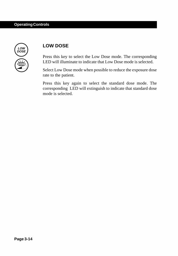
LOW DOSE
Press this key to select the Low Dose mode. The correspondingLED will illuminate to indicate that Low Dose mode is selected.
Select Low Dose mode when possible to reduce the exposure doserate to the patient.
Press this key again to select the standard dose mode. Thecorresponding LED will extinguish to indicate that standard dosemode is selected.

Page 3-15
Operating Controls
ALARM RESET
ALARM RESET
The C-arm counts or accumulates the amount of time that X-raysare generated when an X-ray switch is pressed. The amount ofaccumulated exposure time is indicated on the C-arm control paneldisplay.
If pulse mode is enabled, the amount of time accumulated dependson the length of time an X-ray switch is pressed and the length of thepulses and the number of pulses per second.
Systems within the U.S.
Systems sound an alarm and illuminate the Alarm Reset LED at theend of each 5 minute (default) interval of accumulated fluoro time.To silence the alarm or reset the accumulated fluoro time:
• Press ALARM RESET briefly to silence the alarm.
• Press and hold ALARM RESET for approximately twoseconds to reset the accumulated exposure time to zeroand silence the alarm.

Page 3-16
Operating Controls
Systems outside the U.S.
Systems sound an alarm and illuminate the Alarm Reset LED at theend of each 5 minute (default) interval of accumulated fluoro time.To silence the alarm or reset the accumulated fluoro time:
• Press ALARM RESET briefly to silence the alarm.
• Press and hold ALARM RESET for approximately twoseconds to reset the accumulated exposure time to zeroand silence the alarm.
In addition, when the accumulated fluoro time reaches a preset limit,default is 10 minutes maximum, X-rays will be terminated. Thirtyseconds prior to termination an alarm will sound. To override X-raytermination and silence the alarm, press the ALARM RESET keybriefly.
If you are unable to reset the alarm before X-rays are terminated,release the X-ray switch and then press the X-ray switch again toenable X-rays.
NOTE: The time duration before X-rays are terminated can be adjusted by yourfield service representative.

Page 3-17
Operating Controls
Fast Stop SwitchesFast Stop switches are located on each side of the C-arm control panel. Presseither Fast Stop switch to stop motorized mechanical movement (verticalcolumn) and disable X-rays.
WARNINGIf pressing a Fast Stop switch fails to stop motor movement
or X-rays, place the Workstation power switch in the offposition, or disconnect the power plug from the AC
receptacle.
Figure 3-3. Fast Stop switches are located on each C-arm control panel.
Page 3-18
Operating Controls
If the Fast Stop switch is pressed, on purpose or inadvertently, while anoperator is pressing the vertical column switch, vertical column operation willcease and X-rays will be disabled. After both switches have been released,it may be possible to operate the vertical column. However, X-rays willremain disabled until the system is rebooted.
If the Fast Stop switch is pressed when a run-away condition exists, verticalcolumn motion will cease and X-rays will be disabled. Under this conditionit is not possible to operate the vertical column or take X-rays. Call yourservice representative.
If the Fast Stop switch has been pressed to disable unintended X-rays, do notreboot the system. Call your service representative.

Page 3-19
Operating Controls
X-ray On SwitchThe X-ray ON switch is located on the C-arm control panel housing. Theswitch can be used to take a film exposure, generate Fluoro images or initiateroadmapping on Vascular systems. In essence, it functions just like the leftfootswitch or handswitch and the function is dependant on the imaging modeselected: standard fluoroscopy or vascular imaging.
When generating X-rays in Fluoro mode, the image is displayed on the leftWorkstation monitor. When the X-ray switch is released, X-rays areterminated and the last image or frame of the exposure is retained on the leftmonitor. This is referred to as "Last Image Hold."
Refer to your 1k x1k Workstation Operator's Guide for additionalinformation about imaging modes.
Figure 3-4. The location of the X-ray on switch.
Page 3-20
Operating Controls
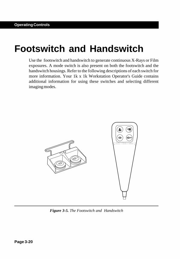
Footswitch and HandswitchUse the footswitch and handswitch to generate continuous X-Rays or Filmexposures. A mode switch is also present on both the footswitch and thehandswitch housings. Refer to the following descriptions of each switch formore information. Your 1k x 1k Workstation Operator's Guide containsadditional information for using these switches and selecting differentimaging modes.
+
Figure 3-5. The Footswitch and Handswitch
Page 3-21
Operating Controls
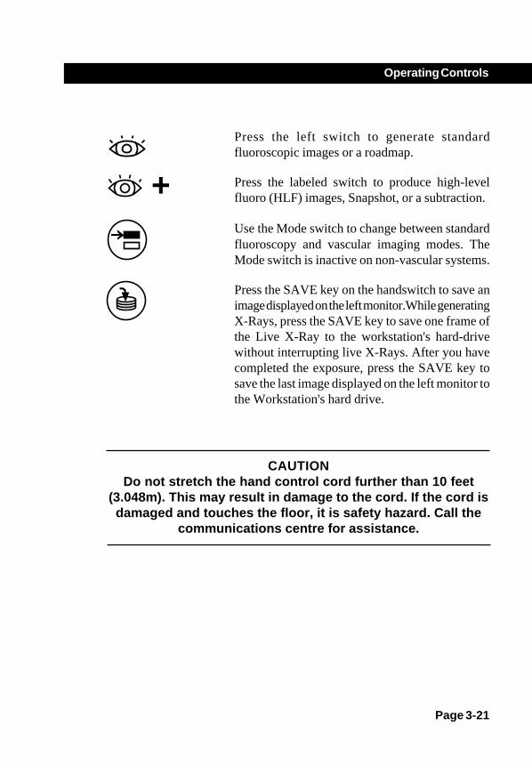
Press the left switch to generate standardfluoroscopic images or a roadmap.
+ Press the labeled switch to produce high-levelfluoro (HLF) images, Snapshot, or a subtraction.
Use the Mode switch to change between standardfluoroscopy and vascular imaging modes. TheMode switch is inactive on non-vascular systems.
Press the SAVE key on the handswitch to save animage displayed on the left monitor.While generatingX-Rays, press the SAVE key to save one frame ofthe Live X-Ray to the workstation's hard-drivewithout interrupting live X-Rays. After you havecompleted the exposure, press the SAVE key tosave the last image displayed on the left monitor tothe Workstation's hard drive.
CAUTIONDo not stretch the hand control cord further than 10 feet
(3.048m). This may result in damage to the cord. If the cord isdamaged and touches the floor, it is safety hazard. Call the
communications centre for assistance.
Mechanical Positioning
OverviewThis chapter describes:
• C-arm identification• Component identification• Moving the C-arm
Chapter 4
Page 4-1

Page 4-2
Mechanical Positioning
C-arm IdentificationThe C-arm has a 9 inch image intensifier (II) attached.
Figure 4-1.Figure 4-1.Figure 4-1.Figure 4-1.Figure 4-1. C-arm.

Page 4-3
Mechanical Positioning
Component Identification
C-arms with 9-inch Image IntensifiersComponent identification is virtually identical for C-arms with 9-inch imageintensifiers. Therefore only the standard C-arm with a 23 cm (9-inch) II isillustrated. Refer to the "Technical Reference" chapter for dimensionaldifferences.
The items listed below identify the location of components used during setupand positioning and correspond to the circled items in the following figure.
1. Horizontal cross-arm handle
2. Horizontal cross-arm brake handle
3. Vertical column lift switches
4. Control panel display
5. Wig-wag brake handle
6. Rotational brake
7. Interface panel (left side cover)
8. Image intensifier handle
9. C-arm orbital rotation brake
10. Rear wheel brake pedal
11. C-arm Handle
12. Steering handle (right side only)

Page 4-4
Mechanical Positioning
Figure 4-2. Component identification for C-arms.
12
11
10
9
8
7
6 5
4
3 2
1

Page 4-5
Mechanical Positioning
C-arm Orbital RotationThe 9 inch C-arm configuration provides 135o of orbital rotation (90o
underscan and 45o overscan). The back of the C-arm is marked with a scaleto aid in positioning.
Figure 4-3. C-arm Orbital Rotation for 9 inch
Positioning
Page 4-6
Mechanical Positioning
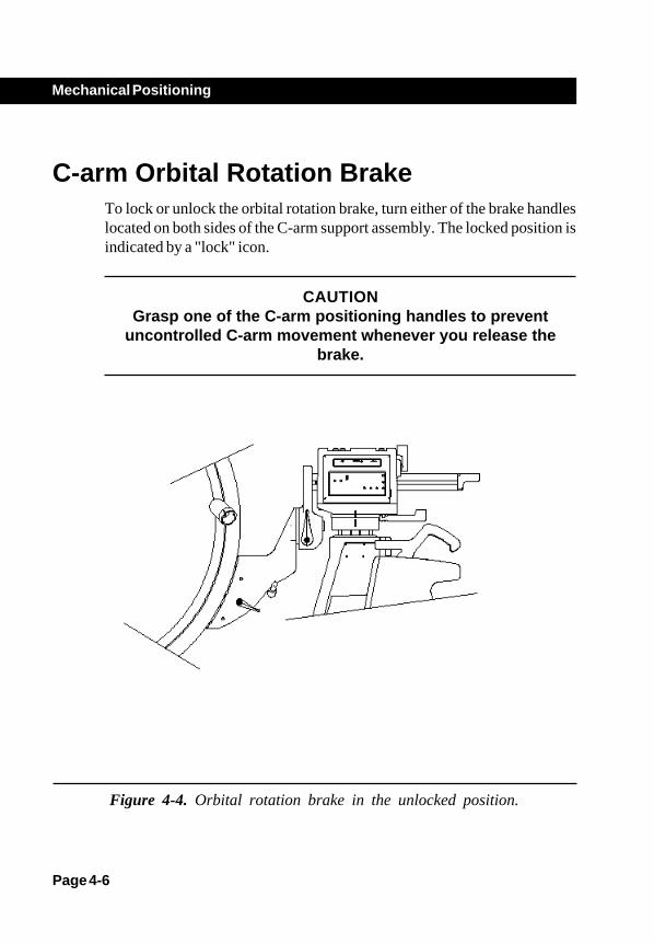
Figure 4-4. Orbital rotation brake in the unlocked position.
C-arm Orbital Rotation BrakeTo lock or unlock the orbital rotation brake, turn either of the brake handleslocated on both sides of the C-arm support assembly. The locked position isindicated by a "lock" icon.
CAUTIONGrasp one of the C-arm positioning handles to prevent
uncontrolled C-arm movement whenever you release thebrake.
Page 4-7
Mechanical Positioning
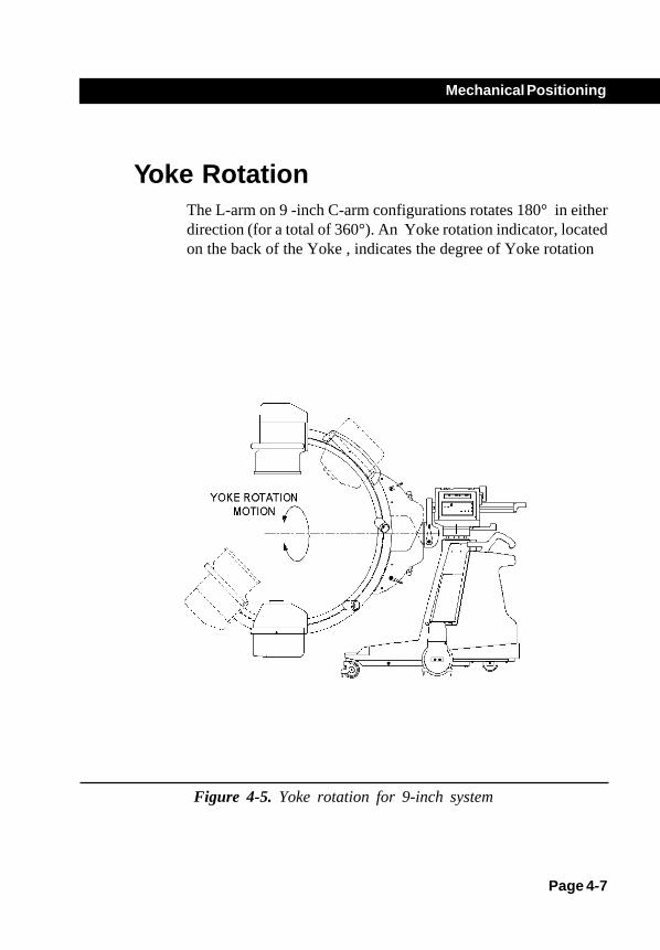
Figure 4-5. Yoke rotation for 9-inch system
Yoke RotationThe L-arm on 9 -inch C-arm configurations rotates 180° in eitherdirection (for a total of 360°). An Yoke rotation indicator, locatedon the back of the Yoke , indicates the degree of Yoke rotation
Page 4-8
Mechanical Positioning
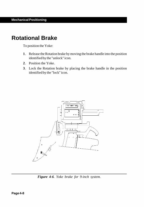
Figure 4-6. Yoke brake for 9-inch system.
Rotational BrakeTo position the Yoke:
1. Release the Rotation brake by moving the brake handle into the positionidentified by the "unlock" icon.
2. Position the Yoke.
3. Lock the Rotation brake by placing the brake handle in the positionidentified by the "lock" icon.
Page 4-9
Mechanical Positioning
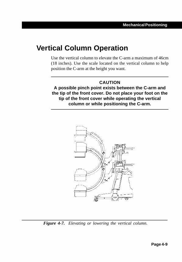
Figure 4-7. Elevating or lowering the vertical column.
Vertical Column OperationUse the vertical column to elevate the C-arm a maximum of 46cm(18 inches). Use the scale located on the vertical column to helpposition the C-arm at the height you want.
CAUTIONA possible pinch point exists between the C-arm and
the tip of the front cover. Do not place your foot on thetip of the front cover while operating the vertical
column or while positioning the C-arm.
Page 4-10
Mechanical Positioning
!
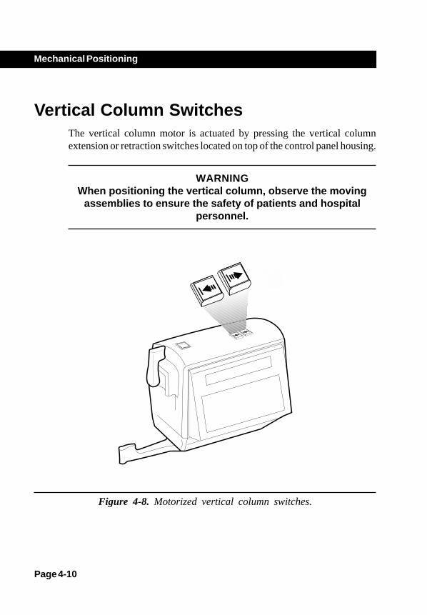
Vertical Column SwitchesThe vertical column motor is actuated by pressing the vertical columnextension or retraction switches located on top of the control panel housing.
WARNINGWhen positioning the vertical column, observe the moving
assemblies to ensure the safety of patients and hospitalpersonnel.
Figure 4-8. Motorized vertical column switches.

Page 4-11
Mechanical Positioning
Horizontal Cross-armThe horizontal cross-arm extends a maximum of 20 cm (8 inches).
Figure 4-9. Positioning the horizontal cross-arm.
Page 4-12
Mechanical Positioning
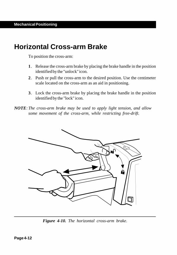
Horizontal Cross-arm BrakeTo position the cross-arm:
1. Release the cross-arm brake by placing the brake handle in the positionidentified by the "unlock" icon.
2. Push or pull the cross-arm to the desired position. Use the centimeterscale located on the cross-arm as an aid in positioning.
3. Lock the cross-arm brake by placing the brake handle in the positionidentified by the "lock" icon.
NOTE: The cross-arm brake may be used to apply light tension, and allowsome movement of the cross-arm, while restricting free-drift.
Figure 4-10. The horizontal cross-arm brake.

Page 4-13
Mechanical Positioning
Wig-WagThe mechanical assemblies attached to the horizontal cross-arm can "Wig-Wag," or move from side-to-side. The total distance travelled from side-to-side is dependent on whether the horizontal cross-arm is extended orretracted. The total distances travelled is listed in the following table for eachsystem:
Item Position 23 cm (9-inch) 1 extended 49.6 cm (19.5") 2 retracted 42.4 cm (16.7")
21
Figure 4-11. Wig-Wag motion for a 23 cm (9-inch) system is shown.
Page 4-14
Mechanical Positioning
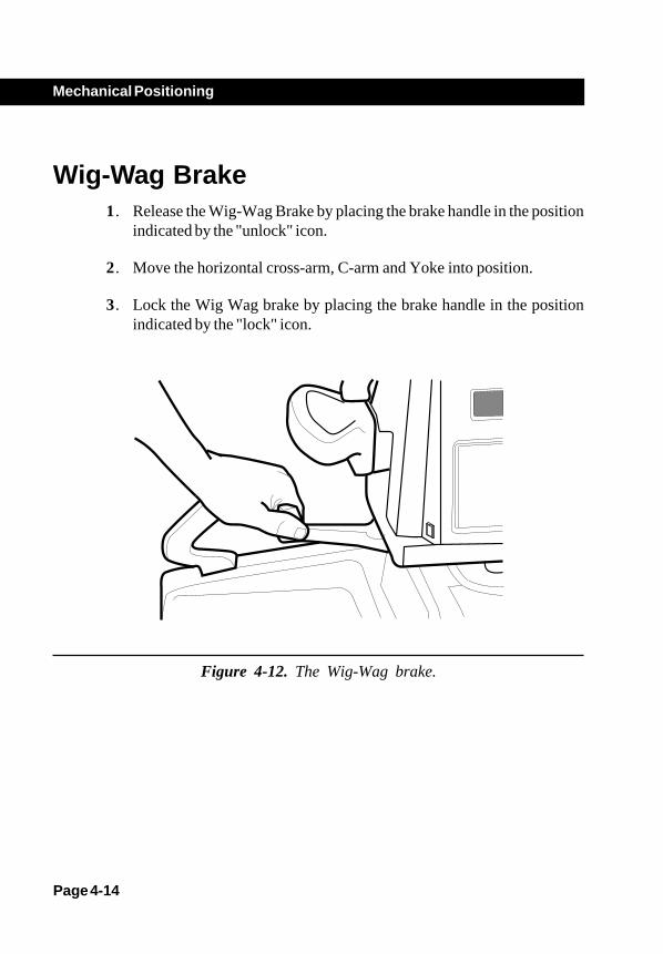
Wig-Wag Brake1. Release the Wig-Wag Brake by placing the brake handle in the position
indicated by the "unlock" icon.
2. Move the horizontal cross-arm, C-arm and Yoke into position.
3. Lock the Wig Wag brake by placing the brake handle in the positionindicated by the "lock" icon.
Figure 4-12. The Wig-Wag brake.

Page 4-15
Mechanical Positioning
FlexiView8800 C-Arm Wheel BrakesThe C-arm brake pedals are located above the rear wheels on both sides ofthe C-arm. The pedals operate much like rocker switches. The pedalpositions are:
Position Description
1 . Locks the rear wheel brakes.
2 . Unlocks the rear wheel brakes allowing the wheels torotate freely.
3 . Locks the rear wheel brakes.
1 2 3
Figure 4-13. C-arm brake pedal positions.
Page 4-16
Mechanical Positioning
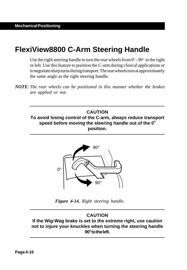
FlexiView8800 C-Arm Steering HandleUse the right steering handle to turn the rear wheels from 0O - 90O to the rightor left. Use this feature to position the C-arm during clinical applications orto negotiate sharp turns during transport. The rear wheels turn at approximatelythe same angle as the right steering handle.
NOTE: The rear wheels can be positioned in this manner whether the brakesare applied or not.
CAUTIONTo avoid losing control of the C-arm, always reduce transport
speed before moving the steering handle out of the 0o
position.
90°
90°
0°
Figure 4-14. Right steering handle.
CAUTIONIf the Wig-Wag brake is set to the extreme right, use cautionnot to injure your knuckles when turning the steering handle
90° to the left.
Page 4-17
Mechanical Positioning
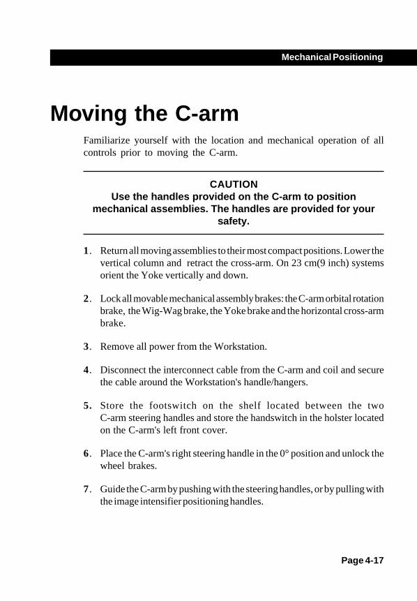
Moving the C-armFamiliarize yourself with the location and mechanical operation of allcontrols prior to moving the C-arm.
CAUTIONUse the handles provided on the C-arm to position
mechanical assemblies. The handles are provided for yoursafety.
1. Return all moving assemblies to their most compact positions. Lower thevertical column and retract the cross-arm. On 23 cm(9 inch) systemsorient the Yoke vertically and down.
2. Lock all movable mechanical assembly brakes: the C-arm orbital rotationbrake, the Wig-Wag brake, the Yoke brake and the horizontal cross-armbrake.
3. Remove all power from the Workstation.
4. Disconnect the interconnect cable from the C-arm and coil and securethe cable around the Workstation's handle/hangers.
5. Store the footswitch on the shelf located between the twoC-arm steering handles and store the handswitch in the holster locatedon the C-arm's left front cover.
6. Place the C-arm's right steering handle in the 0° position and unlock thewheel brakes.
7. Guide the C-arm by pushing with the steering handles, or by pulling withthe image intensifier positioning handles.

Page 4-18
Mechanical Positioning
CAUTIONDo not move the C-arm over inclines greater than 10°. Do notmove the C-arm up or down stairs or steps. Do not lock the
C-arm in place on an incline greater than 5°.
8. When you reach your destination place the C-arm wheel brakes in thelocked position.
Page 4-19
Mechanical Positioning
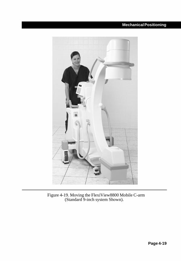
Figure 4-19. Moving the FlexiView8800 Mobile C-arm(Standard 9-inch system Shown).
Radiographic Film
OverviewUse film mode to produce radiographic films. The film cassette holderdescribed in this section is available as an option and should be used ifyou use film mode.
This chapter describes how to:
• Setup and make a film exposure.• Prearm for a film exposure.
Chapter 5
Page 5-1

Page 5-2
Radiographic Film
Setup and Make a Film ExposurePerform the following steps to make a film exposure:
1. Press the FILM button on the C-arm control panel.
NOTE: Once film mode has been selected, the field size and collimator settingsare locked. If further adjustments are required, you must first reenterFluoro mode.
2. Place the cassette holder over the face of the image intensifier with thehandle opened out.
Figure 5-1. Installation of cassette holder.
Page 5-3
Radiographic Film
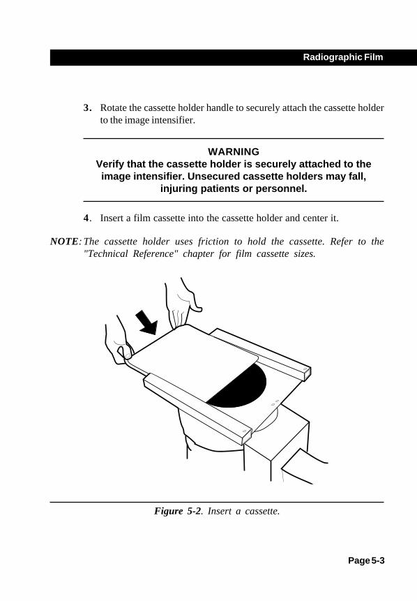
3. Rotate the cassette holder handle to securely attach the cassette holderto the image intensifier.
WARNINGVerify that the cassette holder is securely attached to theimage intensifier. Unsecured cassette holders may fall,
injuring patients or personnel.
4. Insert a film cassette into the cassette holder and center it.
NOTE: The cassette holder uses friction to hold the cassette. Refer to the"Technical Reference" chapter for film cassette sizes.
Figure 5-2. Insert a cassette.

Page 5-4
Radiographic Film
WARNINGVerify that the cassette is held securely within the cassette
holder. Unsecured film cassettes may fall, injuring patients orpersonnel.
5. Adjust the radiographic technique (kVp and mAs) to the desired levels.
6. Press and hold any X-ray switch.
NOTE: There is a 2-second delay after the switch is pressed while the filamentis heated. The beginning of the exposure is signaled by a beep. The endof the exposure is signaled by three quick beeps.
7. Release the X-ray switch at the end of the exposure (when you hearthree quick beeps).
NOTE: If a film exposure is terminated prematurely, the message RELEASEDEARLY will be displayed briefly on the C-arm control panel. When themessage is no longer displayed, you can continue.
8. Remove the film cassette by pushing the cassette out of the cassetteholder.
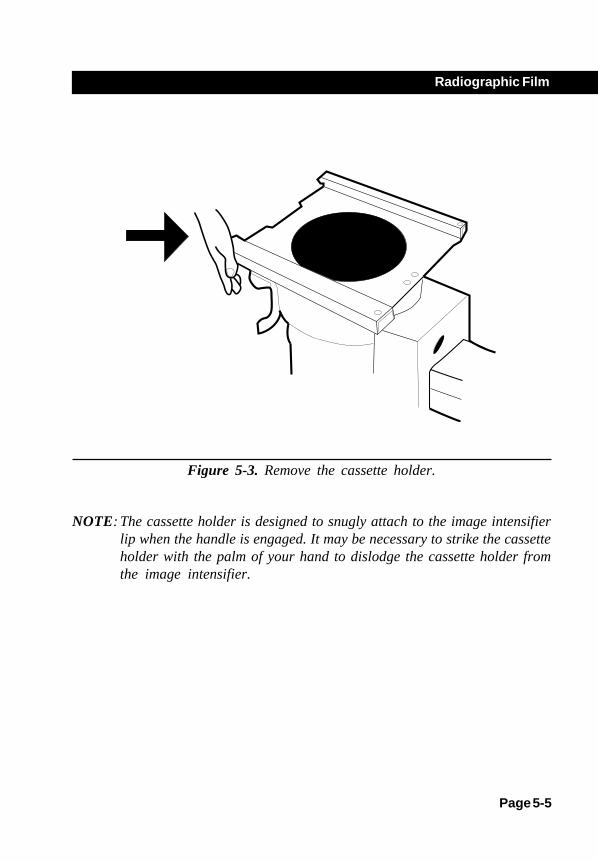
9. To remove the cassette holder, open the cassette holder handle and pressfirmly against the side of the cassette holder.
Page 5-5
Radiographic Film
Figure 5-3. Remove the cassette holder.
NOTE: The cassette holder is designed to snugly attach to the image intensifierlip when the handle is engaged. It may be necessary to strike the cassetteholder with the palm of your hand to dislodge the cassette holder fromthe image intensifier.
Page 5-6
Radiographic Film
Prearm for Film ExposureThe system can be prearmed in film mode up to sixty seconds in advanceto avoid the 2-second delay when the X-ray switch is pressed. To prearmthe system:
1. Set the desired technique (kVp and mAs).
2. Press any X-ray switch and release before the 2-second delay expires.
NOTE: The C-arm control panel displays the message "ARMED."
3. When you are ready to make the exposure, press the X-ray switchagain. The system will initiate an exposure immediately. There will be nodelay.
4. If you decide not to make a prearmed exposure, wait sixty seconds orpress any control panel key (except the X-ray on key) to cancelprearming.

Maintenance
OverviewThis section describes routine performance checks that you can perform toensure that the system is operating correctly. The performance checks listedare not intended to substitute for scheduled periodic maintenance. Ifproblems are found during these checks, contact a qualified service engineerto troubleshoot and repair the system.
In addition to performance checks, safe cleaning practices are included anda description of periodic maintenance that should be performed. All periodicmaintenance should be performed by a GE Medical System's representativeor a qualified service engineer.
Prior to performing any of the performance checks in this section, it isimportant that potential hazards associated with these tasks are understood.Review the "Introduction and Safety" chapter of this guide before proceeding.
Page 6-1
Chapter 6

Page 6-2
Maintenance
WARNINGCircuits inside the equipment use voltages which are capableof causing serious injury or death from electrical shock. Donot remove the covers or perform any type of service task,
except as specifically instructed here.
Move the system into a safe operating area prior to beginning these checksand observe all radiation safety precautions. The performance checks shouldbe performed as often as equipment use and circumstances warrant.Extensive use warrants increasing the frequency of performance checks. Inaddition, circumstances such as accidents during transport or exposure toexcessive fluids may warrant that performance checks be performed toverify operation of the equipment.
Page 6-3
Maintenance
Performance Checks
Mechanical Performance Check1. Check the Wig-Wag brake operation. Check Wig-Wag for ease of
movement (side to side swing) without excessive play.
2. Check the Horizontal Cross-arm brake operation. Extend and retract theHorizontal Cross-arm. Check for ease of movement without excessiveplay.
3. Check the C-arm orbital rotation brake operation. Check orbital rotationof the C-arm for ease of movement without excessive play.
4. Check Yoke rotation on standard systems with 9-inch image intensifiers.On 9 inch II systems, check Yoke brake operation. Move the Yoke andverify that no excessive mechanical drift occurs.
5 Check the operation of the rear wheel pedal brakes.
6 Check for proper operation of the steering handle and control of the rearwheels. Check for ease of movement without excessive play.

Page 6-4
Maintenance
Electrical Performance Check1. Inspect the high voltage cables for signs of wear and abrasion.
2. Inspect the footswitch and hand control cables for signs of wear andabrasion.
3. Perform the Workstation performance checks. Refer to your 1k x 1kWorkstation Operator's Guide.
4. Turn the system on and verify that the system successfully completes thepower-up sequence.
5. Raise the vertical column by pressing the switch located on top of the C-arm's control panel housing.

Page 6-5
Maintenance
Fast Stop Performance CheckThis check is performed as a matter of routine operator maintenance toensure that the Fast Stop safety feature is functioning properly. Refer to theoperator performance checks contained in the "Maintenance" chapter of thisguide. In addition, perform this check as often as conditions, such as removalfrom long term storage and exposure to fluids, warrant it.
1. Press and hold one of the vertical column control switches and whilemotion is occurring, press either Fast Stop switch.
2. Verify that mechanical motion stops and a message stating that FastStop has been activated appears on the C-arm control panel display.
3. Press any X-ray switch and verify that X-rays are disabled.
4. Cycle the Workstation power switch to off and then on to reboot thesystem.
NOTE: Images and annotations will be lost when the system is restartedunless you have saved them. If you have saved images you canaccess them through the Workstation's Image Directory function.

Page 6-6
Maintenance
Fluoro Mode Performance Check
WARNINGThis procedure produces X-rays. Take the appropriate
precautions.
1. Position the C-arm so that the X-ray head is directly above the imageintensifier.
2. Place a suitable test object on the face of the image intensifier tube.
3. Verify that auto mode is selected. The LED next to the AUTO key(generator grouping) on the C-arm control panel will be illuminated.
4. Press the X-ray on switch located on top of the control panel housing.Verify that a digitized fluoro image of the object appears on the leftmonitor and that it remains there after the exposure is terminated.
5. Connect the footswitch and hand control and while pressing a footswitchor handswitch X-ray switch:
a) Verify operation of the C-arm image orientation keys:rotation and image reversal.
b) Verify operation of the field size selection keys: NORM, MAG1 andMAG2.
c) Verify operation of the motorized collimation controls: leaverotation, iris collimation, and leave open/close.
d) On vascular systems verify operation of the MODE switch,located on the footswitch and handswitch.
Page 6-7
Maintenance
Film Mode Performance Check
WARNINGThis procedure produces X-rays. Take appropriate
precautions.
1. Select film mode and enter the technique: 60 kVp @ 2.5 mAs.
2. Install the film cassette holder on the image intensifier and load a filmcassette.
3. Press the footswitch. Wait for 2 seconds approximately before theX-ray ON indicator lights.
4. Release the footswitch after you hear three beeps.
5. Develop the film and inspect the exposure.

Page 6-8
Maintenance
CleaningMake sure the system is turned off and unplugged before cleaning. Clean thecovers and panels periodically with a damp cloth. Use a mild detergent, ifnecessary, to remove scuffs and stains. Do not use any solvents which maydamage or discolor paint finishes or plastic components.
CAUTIONThe C-arm is not waterproof. Be careful not to spill or splash
liquids where they can enter electronic assemblies.
Page 6-9
Maintenance
Periodic MaintenancePeriodic maintenance should be performed by a GE Medical Systems fieldservice engineer or staff that have been trained by GE Medical Systems .Periodic maintenance should be performed on a semiannual basis. Periodicmaintenance and service includes the following:
• Manual movement of mechanical assemblies and brakes.
• Electromechanical performance.
• Safety interlock performance (Fast Stop circuit).
• Electrical performance including exterior cabling inspection, groundcontinuity, line voltage regulation, power supply operation, battery and staticdischarge component performance.
• Ventilation including circuits and fans.
• Imaging chain performance including image resolution, beam alignment, autotechnique tracking, and entrance exposure calibration.
• Functional operation of any remaining features.
Page 7-1
Chapter 7
Display Messages
OverviewThis chapter describes messages that appear on the C-arm control panelduring system operation. The messages are listed in alphabetical order.Messages may indicate any of the following:
• Status messages• Error messages• Warning messages

Page 7-2
Display Messages
Error Recovery StepsPerform the following error recovery procedure if you encounter problemsduring start-up or operation:
1. Some messages require that you press a control panel key on the C-armto resume system operation. If this fails to restore system operation, thenproceed with step 2.
2. If a message persists then place the Workstation power switch in the offposition; wait five seconds, then place the power switch in the on position.If this fails to restore normal operation then proceed with step 3.
3. Turn the power switch off and call for service. Refer to the "Introductionand Safety" chapter for communication center telephone numbers. Donot continue using the system.
WARNINGIgnoring error and warning messages may result in
equipment damage and personal injury.
Page 7-3
Display Messages
Messages
4 HOUR WARM-UP REQUIRED - PRESS ANY KEY If the systemhas been stored for more than 60 days, a warm-up period is necessary forion removal from the image intensifier tube. Leave the system on with nooperation for 4 hours. Press any C-arm control panel key to continue.
24 HOUR RECHARGE REQUIRED - X-RAYS DISABLED If thesystem has been in storage for more than six months, the batteries needrecharging. X-rays are disabled. Leave the Workstation power cord pluggedin, make sure the interconnect cable is properly connected, and wait 24 hoursbefore use. The system does not need to be turned on.
ANODE IS HOT - XX% This message alternates with the techniquedisplayed on the control panel display and an alarm sounds. The anodetemperature is at 80% of its rated heat capacity or greater. The alarm maybe disabled by pressing the ALARM RESET key on the control panel.Continued use without cooling may damage the X-ray tube. Althoughfluoroscopy is not prevented, you should wait for the tube to cool beforemaking another exposure. HLF and film exposures are not allowed.
WARNINGWhen the ANODE IS HOT - XX% message displays, personnelshould avoid body contact with the X-ray tube. Do not allow
the X-ray tube housing to contact the patient.
Page 7-4
Display Messages
ANODE IS WARM - XX% This message will alternate with thetechnique displayed on the control panel display. Anode temperature is at70% of its rated heat capacity or greater. You may continue with fluoroscopy,but discretion is advised.
WARNINGWhen the ANODE IS WARM - XX% message displays,
personnel should prevent all body contact with the X-raytube.
ARMED This message is displayed as the system prepares the techniquefor a film exposure. If the X-ray switch has not been pressed after 60seconds, the message will be removed from the display.
BATTERY CHARGE - XX% If the effective battery charge drops tobetween 70 to 40 percent, this message will alternate with the techniquedisplayed on the control panel display. Fluoro, film and HLF exposures arestill allowed. To charge the batteries, leave the system plugged into an ACreceptacle with the interconnect cable in place between the C-arm and theWorkstation. The Workstation power switch should be turned to the offposition. Normally, a full battery recharge requires only a few hours. If thebatteries are further discharged without adequate recharge time, the effectivecharge may drop below 70 percent.

Page 7-5
Display Messages
BATTERY CHARGE - XX%/WAIT If the effective battery chargedrops below 40 percent, this message will alternate with the techniquedisplayed on the control panel display. The WAIT message appears in thecenter of the technique display. Exposures are allowed in fluoro mode but filmand HLF exposures are not allowed until the battery has recharged. Tocharge the batteries, leave the system plugged into an AC receptacle with theinterconnect cable in place between the C-arm and the Workstation. TheWorkstation power switch should be turned to the off position.
CHARGER FAILED If the battery charger fails at boot-up, this error isdisplayed and the system will not operate. Perform the error recovery stepsdescribed at the beginning of this chapter.
If the failure occurs during operation the message will alternate with thetechnique displayed on the control panel. Continued use will result in systemfailure. Call your service representative as soon as possible.
COLLIMATOR CAL REQUIRED - PRESS ANY KEY The softwarehas determined that the current collimator iris or leave position values do notmatch the reference values stored in memory. Press any key to continue. Callyour service representative as soon as possible.
COL IRIS POTENTIOMETER ERROR - PRESS ANY KEY Thesoftware has sensed that the collimator iris potentiometer is not working andtherefore the iris position cannot be determined. Press any key to continue.Call your service representative as soon as possible.
Page 7-6
Display Messages
COL IRIS TOO LARGE The collimator iris is larger than the controlpanel indicates. This message will alternate with the technique displayed onthe control panel display.
CAUTIONContinuing system operation when the COL IRIS TOO
LARGE message is displayed may result in over exposing thepatient due to a larger than indicated field size. Complete the
current procedure if necessary, then call for service.
COL IRIS UNSTABLE The iris collimator motor control cannot maintainposition tolerance. This message alternates with the technique displayed onthe control panel display. You may continue to use the system, although theiris instability may degrade the image at the edges of the X-ray field.Complete the current procedure if necessary and then call your servicerepresentative.
COLLIMATOR STUCK This message alternates with the techniquedisplayed on the control panel display. The collimator iris motor is unable toopen or close the collimator iris. You may continue to use the system,although you will not be able to adjust the collimator iris. Complete the currentprocedure if necessary and then call your service representative.
COMMUNICATION FAILED System communication has failed. TheFlexi view 8800 Mobile C-arm is not allowed to take X-rays under theseconditions. Wait for approximately one minute for this condition to clear andif it does not, perform the error recovery steps at the beginning of the chapter.

Page 7-7
Display Messages
CONTROL PANEL ERROR Communication to the control panel hasbeen lost, terminating system operation. Perform the error recovery stepsdescribed at the beginning of this chapter.
DATA ERROR Corrupted software or data has been detected. X-raysare disabled. Perform the error recovery steps described at the beginning ofthis chapter.
FAST STOP ACTIVATED, POWER OFF WAIT 5 SECONDS: This message will display after a FAST STOP key has been pressed. Push theWorkstation power switch to OFF and then ON to restart the system.
If you did not press a FAST STOP key and this message is displayed, ahardware or software fault has occurred. Perform the error recovery stepsdescribed at the beginning of this chapter.
FILAMENT CAL REQUIRED - PRESS ANY KEY The system hassensed that the filaments have not been calibrated. It is possible to receivemultiple mA errors, if this condition exists. Call your service representativeas soon as possible to perform a calibration.
WARNINGIf the procedure is continued when the FILAMENT CAL
REQUIRED message is displayed, the patient may receive ahigher dose than that indicated. Press any
C-arm control panel key to continue with the procedure ifnecessary, then call for service.
Page 7-8
Display Messages
FILAMENT REGULATOR FAILURE - PRESS ANY KEY Thefilament current has been sensed as out of tolerance. You may press any C-arm control panel key to continue. However, the resolution of future imagesmay be degraded. Contact your service representative as soon as possible.
WARNINGIf the procedure is continued when the FILAMENT REG
FAILURE message is displayed, the patient may receive ahigher dose than that indicated. Press any
C-arm control panel key to continue with the procedure ifnecessary, then call for service.
FILAMENT SELECT ERROR - PRESS ANY KEY The filament sizeselected by software does not match the current filament in the PIOhardware. Press any C-arm control panel key to continue. X-rays aredisabled while the message is displayed.
HLF OVERTIME The HLF (High Level Fluoro) exposure has exceededthe preset time interval and has been terminated. The time interval parametersare dependant on the pulses per second selected. This safety precautiondiscourages excessive continuous lengths of time in HLF mode. Thismessage remains displayed until the footswitch is released.
HOUSING IS HOT - XX% This message alternates with the techniquedisplayed on the control panel display and an alarm sounds. The housingtemperature is at 80% of its rated heat capacity or greater. The alarm maybe disabled by pressing the ALARM RESET key on the control panel.Although fluoroscopy is not prevented, you should wait for the tube to coolbefore making another exposure. HLF and film exposures are not allowedat this temperature.
Page 7-9
Display Messages
CAUTIONContinued use without cooling may damage the X-ray tube.Although fluoroscopy is not prevented, you should wait for
the tube to cool before making another exposure.
WARNINGWhen the HOUSING IS HOT - XX% message displays,
personnel should avoid body contact with the X-ray tubehousing. Do not allow the X-ray tube housing to contact the
patient.
HOUSING OVERHEATED This message is displayed when the X-raytube is at 100 percent of its rated housing capacity. Operation is terminated.Let the housing cool.
CAUTIONWhen the HOUSING OVERHEATED message appears, theX-ray tube housing is extremely hot and must be allowed to
cool before taking more exposures.
Avoid body contact with the X-ray tube housing. Do not allowthe X-ray tube housing to contact the patient.
HOUSING WARM - XX% The housing temperature is at 70% of its ratedheat capacity or greater. This message alternates with the techniquedisplayed on the control panel display. You may continue with fluoroscopy,but discretion is advised.
WARNINGWhen the HOUSING WARM - XX% message displays,
personnel should avoid body contact with the X-ray tube. Donot allow the X-ray tube housing to contact the patient.
Page 7-10
Display Messages
GENERATOR ERROR: Software has detected an error in the CANcommunication with Monoblock and also local fault in MonoblockGenerator. The System has to be rebooted. Perform the error recoverysteps described at the beginning of this chapter.
INTERLOCK FAILURE The interlock circuit has failed during systemstart-up. Reboot the system and if the message is displayed again, call forservice.
KEY STUCK - RELEASE, THEN PRESS ANY KEY TO CONTINUEA key press has been sensed on the control panel during boot-up, possiblyindicating a stuck control panel key. Verify that there are not any objectspressing against the control panel. After releasing the stuck key, press anyC-arm control panel key to continue.
A malfunctioning control panel key may interfere with operation if youattempt to continue. Contact your field service representative as soon aspossible.
KEYSWITCH IN STANDBY - XRAYS AND MOTORS DISABLEDThis message will display whenever the X-ray keyswitch located on the C-arm is turned to the standby position. Turn the keyswitch to the on positionto operate the system. If the keyswitch is already in the on position, there maybe a fault in the keyswitch or software. In this case perform the errorrecovery steps described at the beginning of this chapter.
HV GENERATOR ERROR: Software has detected an error in the HighVoltage Generator. The system automatically shuts down, preventingoperation. Perform the error recovery steps described at the beginning ofthis chapter.
HV REGISTER FAIL: Software has detected a failure in the high voltageregister. The system automatically shuts down, preventing operation. Performthe error recovery steps described at the beginning of this chapter.

Page 7-11
Display Messages
KV ON IN ERROR High voltage is being generated without an X-rayswitch being activated, indicating a fault with the high voltage generator. Thesystem will not operate with this error. Perform the error recovery stepsdescribed at the beginning of this chapter.
LIFT SWITCH STUCK If the lift switch is pressed continuously for 30seconds, this message will display briefly. This may indicate a foreign objectis pressing against the switch or a faulty switch or lift circuit. If there is noobject pressing against the switch, perform the error recovery steps describedat the beginning of this chapter.
WARNINGIn the event of uncommanded vertical column movement,
immediately move the C-arm out of the patient environmentuntil the problem has been corrected.
MA ON IN ERROR X-ray current (tube current) has been detectedwithout an X-ray switch being activated, indicating a fault with the X-raygenerator. The system will not operate with this error. Perform the errorrecovery steps described at the beginning of this chapter.
OVERLOAD FAULT This may indicate a fault in the high voltageregulator circuit. The first time this fault is detected, the message appearsonly briefly after an exposure. The second time this fault occurs, the systemautomatically shuts down and the message remains on the display. Performthe error recovery steps described at the beginning of this chapter.
Page 7-12
Display Messages
OVERVOLTAGE FAULT This may indicate an X-ray generator failure.The first time this fault is detected, the message appears only briefly after anexposure. The second time this fault occurs, the system automatically shutsdown and the message remains on the display. Perform the error recoverysteps described at the beginning of this chapter.
PLEASE WAIT This message may be displayed briefly on the controlpanel when the system is updating generator data or performing internaltests. The message should clear within moments. If the message does notclear within 30 seconds to a minute, perform the error recovery stepsdescribed at the beginning of this chapter.
PRECHARGE CIRCUIT TIMEOUT The contact relay has failed toclose during the start-up process. This condition results in automatic systemshutdown. Perform the error recovery steps described at the beginning of thischapter.
PRECHARGE VOLTAGE ERROR The precharge voltage has beensensed as too high during the start -up process. This condition results inautomatic system shutdown. Perform the error recovery steps described atthe beginning of this chapter.
RELEASED EARLY During a film exposure, the X-ray switch wasreleased before the desired mAs was reached. The exposure time may havebeen too short for a good image. This message appears briefly at the end ofthe terminated exposure. Using a new film in the cassette, press the X-rayswitch and allow enough time for the system to terminate the exposure.

Page 7-13
Display Messages
WARNING, HIGH KV - PRESS ANY KEY An error has been detectedin the kV loop. The actual kVp is higher than that indicated on the controlpanel display and is not within specified tolerances.
WARNINGContinuing with the procedure when the WARNING, HIGH KV
message has been displayed may subject the patient to ahigher dose than that indicated. Press any C-arm control
panel key to continue with the procedure.
WARNING, HIGH MA - PRESS ANY KEY A calibration error hasbeen detected. The actual mA is higher than that indicated on the controlpanel display and is not within specified tolerances.
WARNINGContinuing with the procedure when the WARNING, HIGH
MA message has been displayed may subject the patient to ahigher dose than that indicated. Press any C-arm control
panel key to continue with the procedure.

Page 7-14
Display Messages
WARNING, LOW KV - PRESS ANY KEY An error has been detectedin the kV loop. The actual kVp is lower than that indicated on the control paneldisplay and is not within specified tolerances. Lower kVp may result in poorimage quality. Press any C-arm control panel key to continue.
WARNING, LOW MA - PRESS ANY KEY A calibration error has beendetected. The actual mA is lower than that indicated on the control paneldisplay and is not within specified tolerances. Lower mA may result in poorimage quality. Press any C-arm control panel key to continue.
X-RAY OVERTIME - PRESS ANY KEY The film shot has continuedbeyond the time required to achieve the correct exposure and software hasterminated the exposure. Press any control panel key to continue.
WARNINGWhen the X-RAY OVERTIME message is displayed, the
patient may have received a higher dose than expected andcontinued film exposures may result in a higher than
expected dose and longer exposure times.
X-RAY SWITCH SECURITY ERROR A mismatch between thehandswitch or footswitch and a security line has been sensed. Systemoperation is terminated. Call your service representative.
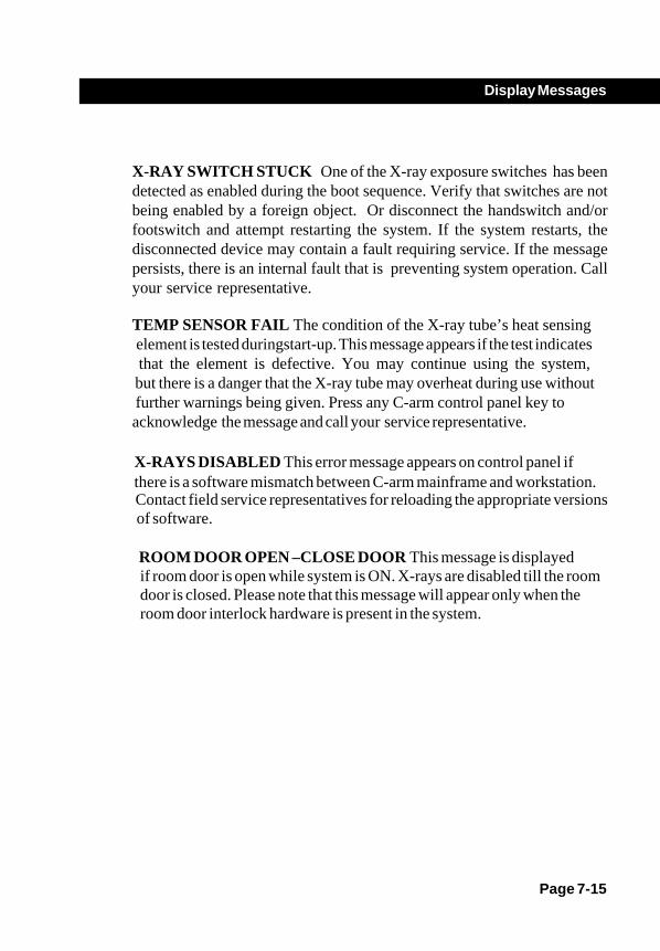
Page 7-15
Display Messages
X-RAY SWITCH STUCK One of the X-ray exposure switches has beendetected as enabled during the boot sequence. Verify that switches are notbeing enabled by a foreign object. Or disconnect the handswitch and/orfootswitch and attempt restarting the system. If the system restarts, thedisconnected device may contain a fault requiring service. If the messagepersists, there is an internal fault that is preventing system operation. Callyour service representative.
TEMP SENSOR FAIL The condition of the X-ray tube’s heat sensing element is tested duringstart-up. This message appears if the test indicates that the element is defective. You may continue using the system, but there is a danger that the X-ray tube may overheat during use without further warnings being given. Press any C-arm control panel key to acknowledge the message and call your service representative.
ROOM DOOR OPEN –CLOSE DOOR This message is displayed
of software.Contact field service representatives for reloading the appropriate versionsthere is a software mismatch between C-arm mainframe and workstation.X-RAYS DISABLED This error message appears on control panel if
room door interlock hardware is present in the system.door is closed. Please note that this message will appear only when theif room door is open while system is ON. X-rays are disabled till the room
Labels and Symbols
OverviewThis chapter describes labels and symbols that are located on yourFlexiView8800 Mobile C-Arm and that are not described elsewhere.
Two types of labels are described: warning labels and regulatory certificationlabels. Warning labels define potential hazards and advise against misuse thatmight result in personal injury. Familiarize yourself with these labels and theirmeanings in order to ensure a safe environment for both the patient andyourself. Regulatory labels indicate that the system meets the requirementsof specific governmental, medical and industrial organizations.
Symbols are provided to visually represent concepts such as locked andunlocked brake positions or the proper transport position of the C-arm. Manyof the symbols described here are listed in IEC 417 and ISO 7000.and arenot developed by GE Medical Systems.
Chapter 8
Page 8-1

Page 8-2
Labels and Symbols
LabelsThe system has been tested and certifiedby the German testing and certificationinstitute Verband DeutscherElektrotechniker (VDE).
�
The system has been tested and certifiedby the Canadian Standards Association tocomply with applicable U.S. and CanadianStandards.
This symbol indicates the system was testedby a Notified Body and was found to be incompliance with the requirements of allrelevant directives and standards in effectwithin the European Union at the time ofmanufacture
These labels (for the system and certifiedcomponents) certify that the FlexiView8800system meets applicable federal standardsand regulations for X-ray equipment as ofthe date of manufacture..
0459
THIS EQUIPMENT IS CERTIFIED TO BE IN COMPLIANCE WITH THEAPPLICABLE STANDARDS OF THE CODE OF FEDERAL REGULATIONS,
TITLE 21, SUBCHAPTER J, AS OF THE DATE OF MANUFACTURE
Date of Mfr.
OEC MEDICAL SYSTEMS, INC. Model No.
GE OEC Medical Systems GmbH90530 WENDELSTEIN Serial No.
GERMANY
THIS EQUIPMENT IS CERTIFIED TO BE IN COMPLIANCE WITH THEAPPLICABLE STANDARDS OF THE CODE OF FEDERAL REGULATIONS,
TITLE 21, SUBCHAPTER J, AS OF THE DATE OF MANUFACTURE
Date of Mfr.
OEC MEDICAL SYSTEMS, INC. Model No.
GE Medical Systems X - Ray(South Asia) Ltd. Serial No.
#122, Part (1), Export Promotion Industrial Park,Whitefield, Bangalore – 560 066, INDIA
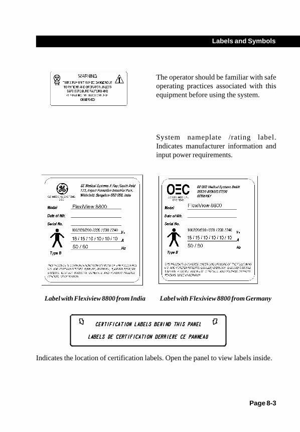
Page 8-3
Labels and Symbols
The operator should be familiar with safeoperating practices associated with thisequipment before using the system.
System nameplate /rating label.Indicates manufacturer information andinput power requirements.
Indicates the location of certification labels. Open the panel to view labels inside.
Label with Flexiview 8800 from India Label with Flexiview 8800 from Germany

Page 8-4
Labels and Symbols
SymbolsIndicates the Equipotential terminal on the8800 C-Arm. This terminal allowsconnection between the C-arm and theequipotential bus bar of the facility.
Attention, see accompanyingdocumentation.
Near the interconnect connector on the C-arm this symbol means that the interconnectcable must be connected to the C-armprior to plugging the power cord into an ACreceptacle.
On the C-arm transport label, this symbolmeans there is information contained in theOperator Manual for positioningsubassemblies for transport.
IP68 This symbol is located on the bottom ofyour footswitch. The electrical switchingmechanism within the footswitch isprotected from exposure to dust and theeffects of continuous immersion in water.However, placement inside a protectivecover is recommended.
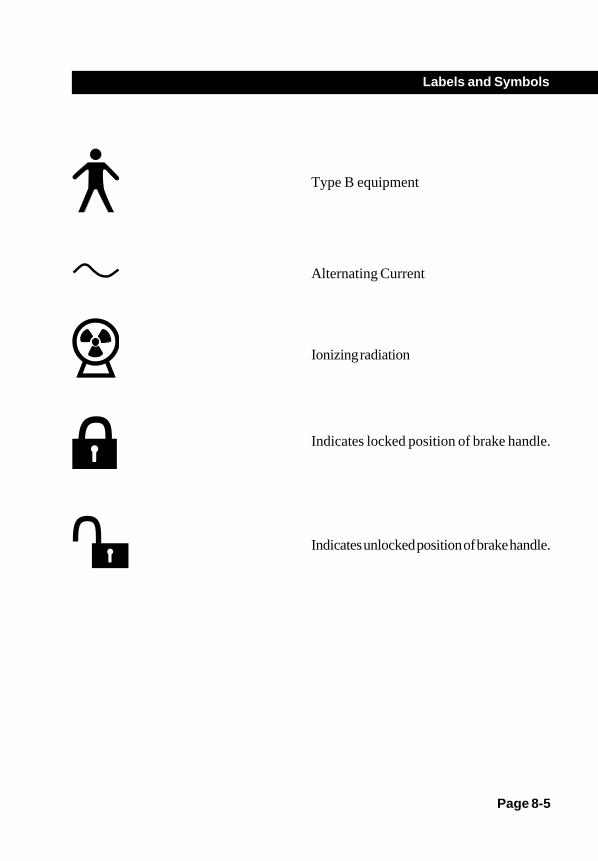
Page 8-5
Labels and Symbols
Type B equipment
Alternating Current
Ionizing radiation
Indicates locked position of brake handle.
Indicates unlocked position of brake handle.

Page 8-6
Labels and Symbols
This symbol marks the approximate locationof the X-ray tube focal spot projected ona straight line at right angles to the centralaxis of the beam.
This symbol indicates the locations of FastStop switches on the C-arm.
This symbol indicates that tthe 8800 C-Arm mechanical subassemblies should beplaced in their most compact position beforetransporting or moving the system. Referto the chapter on positioning for directionson moving the 8800 C-Arm.

Technical Reference
OverviewThe policy of GE Medical Systems , is one of continual product developmentand improvement. For this reason, GE Medical Systems , reserves the rightto change the operating characteristics and specifications of newer productsat any time, without prior notice, and without incurring any obligation relatingto previously manufactured items.
The specifications listed are limited to general performance and physicaldata. Specifications of optional equipment provided by other manufacturersare given in the applicable manuals provided with those options.
Page 9-1
Chapter 9

Page 9-2
Technical Reference
Classification TypeClass I Equipment (as defined by IEC 60601-1)Type B protection against electric shockOrdinary protection against ingress of waterNon AP(Non-anesthetic Proof)Continuous Operation (Refer to the fluoroscopic and film mode duty cyclespecification contained in Generator Operating Parameters.)
Electromagnetic CompatibilityStatement
This equipment generates and uses radio frequency energy and must beinstalled and used according to the manufacturer’s instructions in order toavoid receiving radio frequency interference. If this equipment generates orreceives interference do the following to correct the problem:
• Verify that the equipment is the cause by turning the system onand off.
• Reorient the equipment until the interference stops.• Relocate the equipment with respect to other equipment in the
room.• Plug the equipment into a different outlet so that the equipment
and the receiver are on different branch circuits.
NOTE: All cables that are used to connect to the D-Sub connector I/O portsof the Workstation must be shielded cables or cables supplied by GEMedical Systems .

Page 9-3
Technical Reference
Optional EquipmentThe following accessories have been tested with, and are Known to work with
the FlexiView8800 Mobile C-arm. Call The communication center toorder optional equipment. Refer to the introduction and safety chapter toobtain the communication centers telephone number:
• GE Medical Systems , Laser Aimer• GE Medical Systems, Film Cassette Holder
Replacement ItemsThe following replacement items can be ordered by calling the communicationcenter. Refer to the Introduction and safety Chapter to obtain thecommunication centers telephone number.
• Film/Paper• Sterile drapes and Cover.

Page 9-4
Technical Reference
Camera Output Video SignalHi-res 1k x 1k pixel, 1260lines/Frame @30Hz, 1320 lines/Frame @25Hz.
Environmental RequirementsAmbient Operating: 50o to 95o F (+10o to +35o C)Temperature
Extended > 2 days: 32o to 104o F (0o to +40o C)Storage andTransportation
Short-term < 2 days: 14o to 131o F (-10o to +55o C)Storage andTransportation
Storage and 15,000 ft. (4572 meters) maximumTransportationAltitude
Operating Altitude 10,000 ft. (3048 meters) maximum
Humidity Operating: 20 to 80%, non-condensingStorage and transport: 10%-80%, condensing
Shock and Vibration 1G at 5-200 Hz for 2 hours
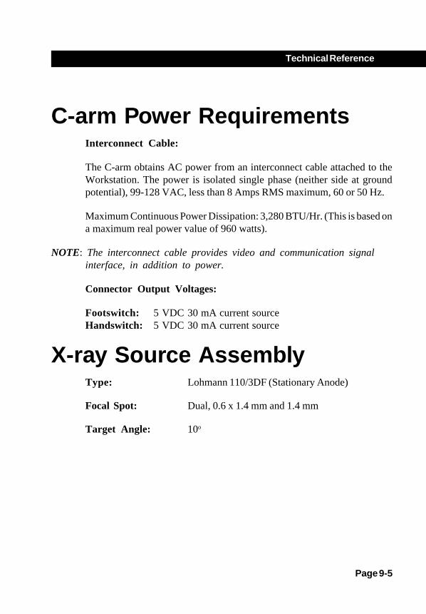
Page 9-5
Technical Reference
C-arm Power RequirementsInterconnect Cable:
The C-arm obtains AC power from an interconnect cable attached to theWorkstation. The power is isolated single phase (neither side at groundpotential), 99-128 VAC, less than 8 Amps RMS maximum, 60 or 50 Hz.
Maximum Continuous Power Dissipation: 3,280 BTU/Hr. (This is based ona maximum real power value of 960 watts).
NOTE: The interconnect cable provides video and communication signalinterface, in addition to power.
Connector Output Voltages:
Footswitch: 5 VDC 30 mA current sourceHandswitch: 5 VDC 30 mA current source
X-ray Source AssemblyType: Lohmann 110/3DF (Stationary Anode)
Focal Spot: Dual, 0.6 x 1.4 mm and 1.4 mm
Target Angle: 10o
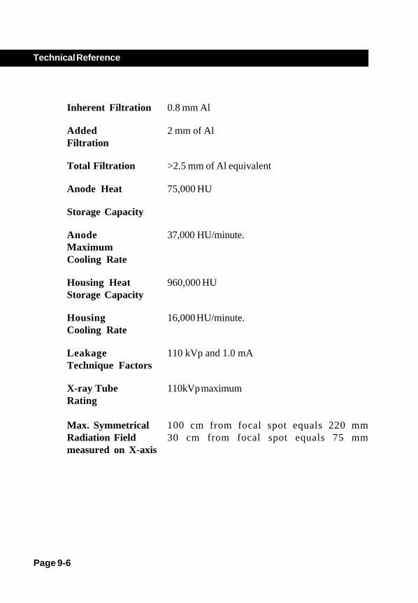
Page 9-6
Technical Reference
Inherent Filtration 0.8 mm Al
Added 2 mm of AlFiltration
Total Filtration >2.5 mm of Al equivalent
Anode Heat 75,000 HU
Storage Capacity
Anode 37,000 HU/minute.MaximumCooling Rate
Housing Heat 960,000 HUStorage Capacity
Housing 16,000 HU/minute.Cooling Rate
Leakage 110 kVp and 1.0 mATechnique Factors
X-ray Tube 110kVp maximumRating
Max. Symmetrical 100 cm from focal spot equals 220 mmRadiation Field 30 cm from focal spot equals 75 mmmeasured on X-axis

Page 9-7
Technical Reference
CollimationFluoroscopy Nominal diameter circle for 9/6/4-inch II
system:23 cm (9-in.)15 cm (6-in.)11 cm (4.5-in.)
Continuously adjustable to an arealess than 5 cm x 5 cm, measured at the imagereceptor plane (II input surface).
Radiography Nominal diameter circle 9-inch II system:23 cm (9-in.)
Continuously adjustable to an arealess than 5 cm x 5 cm, measured at the imagereceptor plane (II input surface).

Page 9-8
Technical Reference
Tube Rating ChartsThe following charts and data describe tube characteristics when operatedwith three-phase full-wave rectification, a reasonable approximation to thehigh frequency generator with minimal ripple.

Page 9-9
Technical Reference

Page 9-10
Technical Reference

Page 9-11
Technical Reference

Page 9-12
Technical Reference
Generator SpecificationsThe following information is provided in accordance with IEC 60601-2-7(1998).
1. Maximum kVpFilm mode 110 kVp @ 20 mA ( max)Normal Mode 110 kVp @ 3 mA (max)HLF Fluoro 110 kVp @ 6 mA (max)Pulsed Fluorography 110 kVp @ 12 mA (max)
2. Maximum mAFilm Mode 20 mA @ 110 kVpNormal Mode 4 mA @ 83 kVpHLF Fluoro 12 mA @ 55kVpPulsed Fluorography 16 mA @ 80 kVp
3. Maximum Output PowerFilm Mod e 2.2 kW for kVp range 50 -110 kVp
4. Lowest mAs settingFilm Mode 1.0 mAs (independent of kVp)
6. Nominal shortest exposure timeFilm Mode 0.2 second
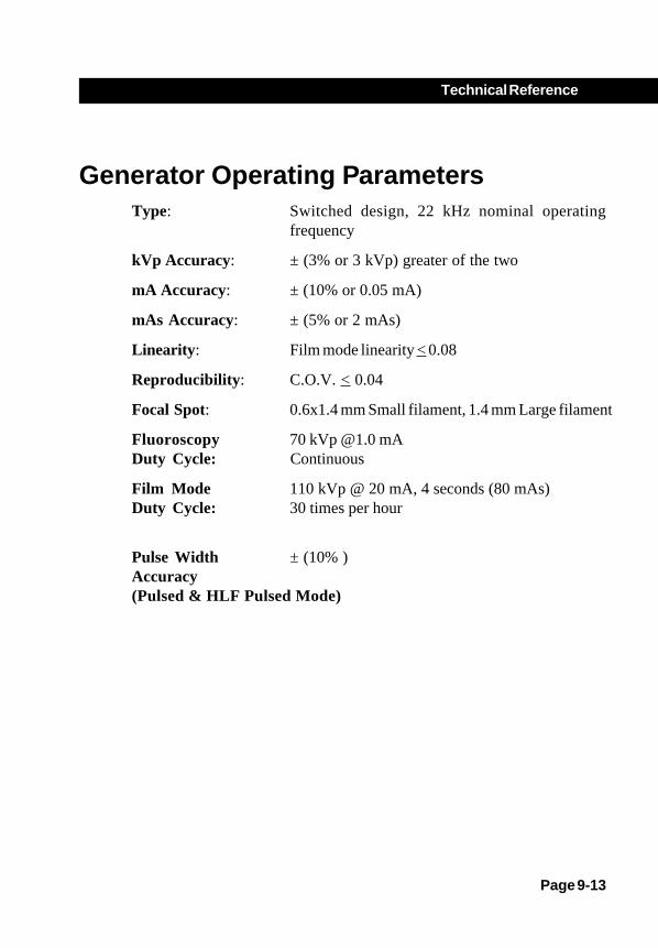
Page 9-13
Technical Reference
Generator Operating ParametersType: Switched design, 22 kHz nominal operating
frequency
kVp Accuracy: ± (3% or 3 kVp) greater of the two
mA Accuracy: ± (10% or 0.05 mA)
mAs Accuracy: ± (5% or 2 mAs)
Linearity: Film mode linearity < 0.08
Reproducibility: C.O.V. < 0.04
Focal Spot: 0.6x1.4 mm Small filament, 1.4 mm Large filament
Fluoroscopy 70 kVp @1.0 mA Duty Cycle: Continuous
Film Mode 110 kVp @ 20 mA, 4 seconds (80 mAs)Duty Cycle: 30 times per hour
Pulse Width ± (10% )Accuracy(Pulsed & HLF Pulsed Mode)

Page 9-14
Technical Reference
Measurement Basis for Technique FactorskVp - The peak value of high voltage generator output in the interval aftera 20 mS delay period to the end of the exposure.
mA - The time average of the current flow into the high voltage cable/X-raytube assembly, beginning at the point where kVp crosses the 35 kVp level.
Time - Measurement of exposure time begins when the kVp crosses the 35kVp level (80% of kVp selected).
mAs - The time integral of mA as defined above.

Page 9-15
Technical Reference
Focal Spot (0.6 x 1.4mm)
Mode mA mAs KVp Pulse PulseRange Range Range Rate (pps) Width (ms)
Auto Fluoro 0.1 to 4.0 N/A 40 to 110 N/A N/A
Manual Fluoro 0.1 to 4.0 N/A 40 to 110 N/A N/A
High Level 0.1 to 12.0 N/A 40 to 110 N/A N/AFluoro Continuous
Pulsed Auto 0.1 to 16.0 N/A 40 to 110 60 HZ: 1,2, 3.75,7.5Fluoroscopy 50 Hz: 1,2.083, 4.167, 50 ( 25)
8.33
Pulsed Manual 0.1 to 16.0 N/A 40 to 110 60 HZ: 1,2, 3.75,7.5Fluoro 50 Hz: 1,2.083, 4.167, 50 (25)
8.33
Snap Shot 16 N/A 40 to 110 N/A 660 ms( 50 Hz) 0
480 ms ( 60 Hz) 0

Page 9-16
Technical Reference
Focal Spot (1.4 mm)
Mode mA mAs kVp Pulse PulseRange Range Range Rate (pps) Width(mS)
Radiographic 5-20 1-80 50 to 110 N/A N/A
Film Cassette Dimensions9-inch II
Metric 24 cm x 30 cmStandard 10 in. x 12 in.

Page 9-17
Technical Reference
DimensionsOEC FlexiView 8800 Mobile C-Arm(9-inch II)

Page 9-18
Technical Reference
Material Safety Data SheetsManufacturer’s Material Safety Data Sheets are available from the manufacturerupon request. Contact the following manufacturer's with regard to the materialslisted.
Dow Corning R 5 Compound (Silicone)-Dow Corning Corporation, SouthSaginaw Road, Midland MI 48686, (517) 496-8306.
Shell Diala R Oil Ax (Oil MSDS No. 60030-5)-Shell, Inc., Product Safety andCompliance, PO Box 4320, Houston, TX 77210, (713) 473-9461.
Panasonic Sealed Lead Acid Battery-Matsushita Industrial Battery Co., Ltd,Battery Storage Division, 11-66 Honsyuku-Cho, Chigasaki, Kanagawa, Japan,(0467) 51-1121.
Sealed Lead Acid Battery-Hawker Energy Products, Inc., 1050 South Broadway,PO Box 5887, Denver, CO., 80217, (303) 744-4806.