Embed Size (px)
Citation preview
Revised 6/22/09 1 of 20 228998
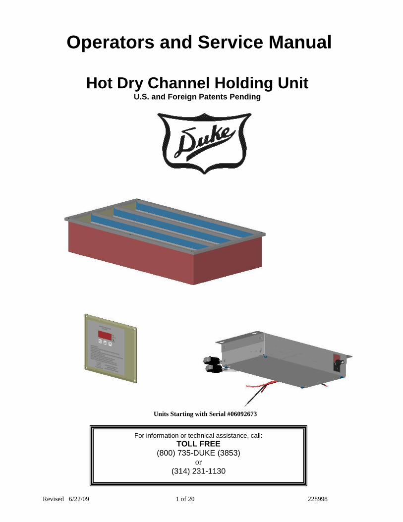
Units Starting with Serial #06092673
For information or technical assistance, call:
TOLL FREE (800) 735-DUKE (3853)
or
(314) 231-1130
Hot Dry Channel Holding Unit U.S. and Foreign Patents Pending
Operators and Service Manual

220
2 of 20
DRY CHANNEL HOLDING UNIT RESTAURANT EQUIPMENT
MANUAL
U.S. and Foreign Patents Pending
DUKE MANUFACTURING CO. TOLL FREE 800-735-DUKE (3853)
314-231-1130
TABLE OF CONTENTS
Manufacturer’s Introduction ....................................................................................................................................... 2 Specification Sheet ...................................................................................................................................................... 3 Installation Instructions............................................................................................................................................... 6 Operating Instructions................................................................................................................................................. 6 Periodic Maintenance, Checklist And Cleaning Guide ............................................................................................. 7 Troubleshooting ........................................................................................................................................................... 8 Electronic Control Fault Indications .......................................................................................................................... 8 Control Programming .................................................................................................................................................. 9 Parts Lists And Illustrations ....................................................................................................................................... 9 Wiring Schematic ....................................................................................................................................................... 12 Wiring Layout for Relay Box Connection…………………………………………………………………………………..13
Manufacturer’s Introduction
The Duke Dry Channel Holding Unit was developed to provide the market with a more efficient method of keeping food warm. This equipment uses electronically controlled heaters to warm aluminum channels to a user programmable temperature. Advantages over steam tables include lower energy and maintenance costs.
Unpacking Unit:
Inspect the shipping carton and/or container, carefully noting any exterior damage on the delivery receipt, which must also be signed by the driver/delivery person.
Unpack and inspect for any damage, which was not evident on the outside of the shipping container (concealed damage). Contact the carrier immediately and file a damage claim with them. Save all packing materials when filing a claim. Freight damage claims are the responsibility of the purchaser and are not covered by the warranty.
Do not attempt to use the unit if damaged.
If unit has been stored in extremely cold area, wait a few hours before connecting power.
Supplier Name: Duke Manufacturing Co. Address: 2305 N. Broadway St. Louis, MO 63102
Model #: HDC3-37.5
HDC4-44 HDC6-37.5
Serial #: Date Received: Date Installed: Telephone: (800) 735-DUKE (3853)
(314) 231-1130 Fax: (314) 231-5074 Service Referral #: Local Service Name
Local Service #
Installation requirements
Spacing Requirements: 1” of spacing required below unit.
Caution! Never pour water into wells. This unit is
designed for dry heating only.
320
3 of 20
DRY CHANNEL HOLDING UNIT RESTAURANT EQUIPMENT
MANUAL
U.S. and Foreign Patents Pending
DUKE MANUFACTURING CO. TOLL FREE 800-735-DUKE (3853)
314-231-1130
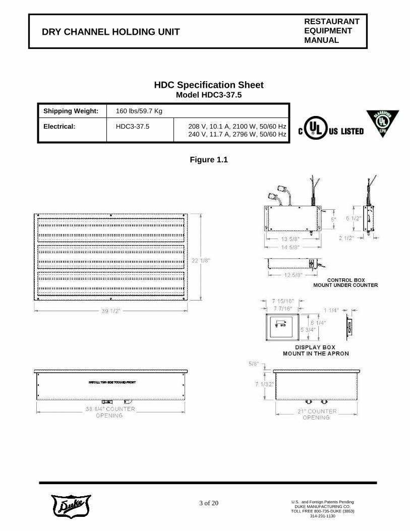
HDC Specification Sheet Model HDC3-37.5
Shipping Weight: 160 lbs/59.7 Kg Electrical: HDC3-37.5 208 V, 10.1 A, 2100 W, 50/60 Hz 240 V, 11.7 A, 2796 W, 50/60 Hz
Figure 1.1

420
4 of 20
DRY CHANNEL HOLDING UNIT RESTAURANT EQUIPMENT
MANUAL
U.S. and Foreign Patents Pending
DUKE MANUFACTURING CO. TOLL FREE 800-735-DUKE (3853)
314-231-1130
HDC Specification Sheet Model HDC4-44
Shipping Weight: 230 lbs/85.8Kg
Electrical: HDC4-44 208 V, 16.3 A, 3400 W, 50/60 Hz 240 V, 18.9 A, 4528 W, 50/60 Hz
Figure 1.2
520
5 of 20
DRY CHANNEL HOLDING UNIT RESTAURANT EQUIPMENT
MANUAL
U.S. and Foreign Patents Pending
DUKE MANUFACTURING CO. TOLL FREE 800-735-DUKE (3853)
314-231-1130
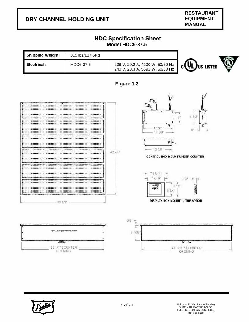
HDC Specification Sheet Model HDC6-37.5
Shipping Weight: 315 lbs/117.6Kg Electrical: HDC6-37.5 208 V, 20.2 A, 4200 W, 50/60 Hz
240 V, 23.3 A, 5592 W, 50/60 Hz
Figure 1.3
620
6 of 20
DRY CHANNEL HOLDING UNIT RESTAURANT EQUIPMENT
MANUAL
U.S. and Foreign Patents Pending
DUKE MANUFACTURING CO. TOLL FREE 800-735-DUKE (3853)
314-231-1130
Installation Instructions
1. Operating temperatures permit safe installation of this holding unit with 1” of spacing between the bottom of the unit and a combustible wall or partition.
2. Do not install the holding unit near any combustible objects or surfaces affected by heat or moisture. 3. When Mounting by the Overhanging Top Rim (in a cut-out in the counter top) -
In order to relieve part of the load from the top rim, the unit should be supported from below with metal components in a manner compatible with the construction of the counter. Models HDC3-37.5 and HDC6-37.5: An extruded gasket is supplied to seal the Dri Channel unit to the counter top. Verify the gasket is in place and seals properly to the counter top. Model HDC4-44 (or for units that do not have a gasket): The underside of the overhanging top rim should have applied to it a generous bead of silicone before the unit is set into the cutout in the counter top. Any excess sealant, which squeezes out between the unit top rim and counter top, should be wiped off before the sealant cures or stripped away with a sharp knife after curing.
4. Electrical -
The voltage and wattage ratings of this holding unit are given on the device nameplate. Connect the holding unit to a circuit having a voltage similar to that stamped on the device nameplate.
Connections to supply line are to be made through the flex conduit whip supplied on the unit.
The body of the appliance should be grounded by connecting the ground wire provided in flex conduit whip to a good electrical ground, such as a water pipe, a steam pipe, or a grounded supply conduit.
The holding unit is not fused and consequently must be connected to a fused circuit equipped with suitable disconnect means, as required by local code authorities.
5. Follow instructions in the Operators Manual PERIODIC MAINTENANCE, CHECKLIST AND CLEANING GUIDE.
Operating Instructions
1. All foodservice equipment should be operated by trained personnel. 2. Do not allow your customers to come in contact with any surface labeled "CAUTION HOT". 3. Never pour water into wells. This unit is designed for dry operation only. 4. Where applicable: Do not cook, warm or hold food directly in wells. 5. Never hold food below 150°F. 6. Always place covers on pans when not serving to prevent food from drying out and to reduce your
operating costs. 7. For most efficient operation, keep empty, covered pans in each channel during preheating and when
the well is not in use. 8. The most satisfactory control settings must be determined by experience based on the nature of the
foodservice and the type of operation as well as individual preference of the restaurant operator. The proper switch setting necessary to keep foods at the desired temperature will vary dependent upon the frequency of turnover, size of food containers, amount of food in each container, room temperature, location of holding unit with respect to range or other heated equipment, air outlets, fans, doors and passageways.

7 of 20
DRY CHANNEL HOLDING UNIT
RESTAURANT EQUIPMENT
MANUAL
U.S. and Foreign Patents Pending
DUKE MANUFACTURING CO. TOLL FREE 800-735-DUKE (3853)
314-231-1130
Periodic Maintenance, Checklist And Cleaning Guide
DAILY Opening Checklist 1. Place the Power Switch to the ON position. 2. Place empty pans or cover the channels with lids. 3. Allow the Product Holding Cabinet to heat for at least 20 min.
Operation Instructions/Adjustments
1. If the control displays a Heating Error it will shut down the affected well. Discontinue use of the affected well until the unit is serviced.
Closing Checklist
1. Turn power switch OFF. 2. Remove all pans and pan covers. 3. Allow unit to cool for approximately 30 minutes. 4. Clean Dry Channel Unit as outlined in the Cleaning Instructions.
Cleaning Instructions
1. Turn unit off and allow unit to cool before surface cleaning. 2. Wipe down the interior and exterior of the Dry Channel Unit with warm water and mild
detergent using a soft cloth. Do not use excessive amounts of water. Plastic scouring pads may be used to remove baked-on food.
3. Clean pans and pan covers using mild detergent and warm water.
Caution! Electrical shock hazard. Do not wash with water jet or hose.
Do not use caustic cleaners, acids, ammonia products or abrasive cleaners or abrasive cloths. These can damage the stainless steel and plastic surfaces.
Troubleshooting
There are no user serviceable parts on the Duke Dry Channel Holding Unit. If a malfunction occurs, then check all switches and circuit breakers. Check rating label and confirm that unit is operating at the proper voltage. If the malfunction still exists, contact your Duke Manufacturing Company authorized service agent or call 1-800-735-3853.
8 of 20
DRY CHANNEL HOLDING UNIT
RESTAURANT EQUIPMENT
MANUAL
U.S. and Foreign Patents Pending
DUKE MANUFACTURING CO. TOLL FREE 800-735-DUKE (3853)
314-231-1130
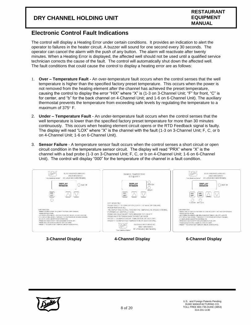
Electronic Control Fault Indications
The control will display a Heating Error under certain conditions. It provides an indication to alert the operator to failures in the heater circuit. A buzzer will sound for one second every 30 seconds. The operator can cancel the alarm with the push of any button. The alarm will reactivate after twenty minutes. When a Heating Error is displayed, the affected well should not be used until a qualified service technician corrects the cause of the fault. The control will automatically shut down the affected well. The fault conditions that could cause the control to display a heating error are as follows:
1. Over – Temperature Fault - An over-temperature fault occurs when the control senses that the well temperature is higher than the specified factory preset temperature. This occurs when the power is not removed from the heating element after the channel has achieved the preset temperature, causing the control to display the error “HIX” where “X” is (1-3 on 3-Channel Unit; “F” for front, “C” is for center, and “b” for the back channel on 4-Channel Unit; and 1-6 on 6-Channel Unit). The auxiliary thermostat prevents the temperature from exceeding safe levels by regulating the temperature to a
maximum of 375 F.
2. Under – Temperature Fault - An under-temperature fault occurs when the control senses that the well temperature is lower than the specified factory preset temperature for more than 30 minutes continuously. This occurs when heating element circuit opens or the RTD Feedback signal is faulty. The display will read “LOX” where “X” is the channel with the fault (1-3 on 3-Channel Unit; F, C, or b on 4-Channel Unit; 1-6 on 6-Channel Unit).
3. Sensor Failure - A temperature sensor fault occurs when the control senses a short circuit or open
circuit condition in the temperature sensor circuit. The display will read “PRX” where “X” is the channel with a bad probe (1-3 on 3-Channel Unit; F, C, or b on 4-Channel Unit; 1-6 on 6-Channel Unit). The control will display “000” for the temperature of the channel in a fault condition.
3-Channel Display 4-Channel Display 6-Channel Display
9 of 20
DRY CHANNEL HOLDING UNIT
RESTAURANT EQUIPMENT
MANUAL
U.S. and Foreign Patents Pending
DUKE MANUFACTURING CO. TOLL FREE 800-735-DUKE (3853)
314-231-1130
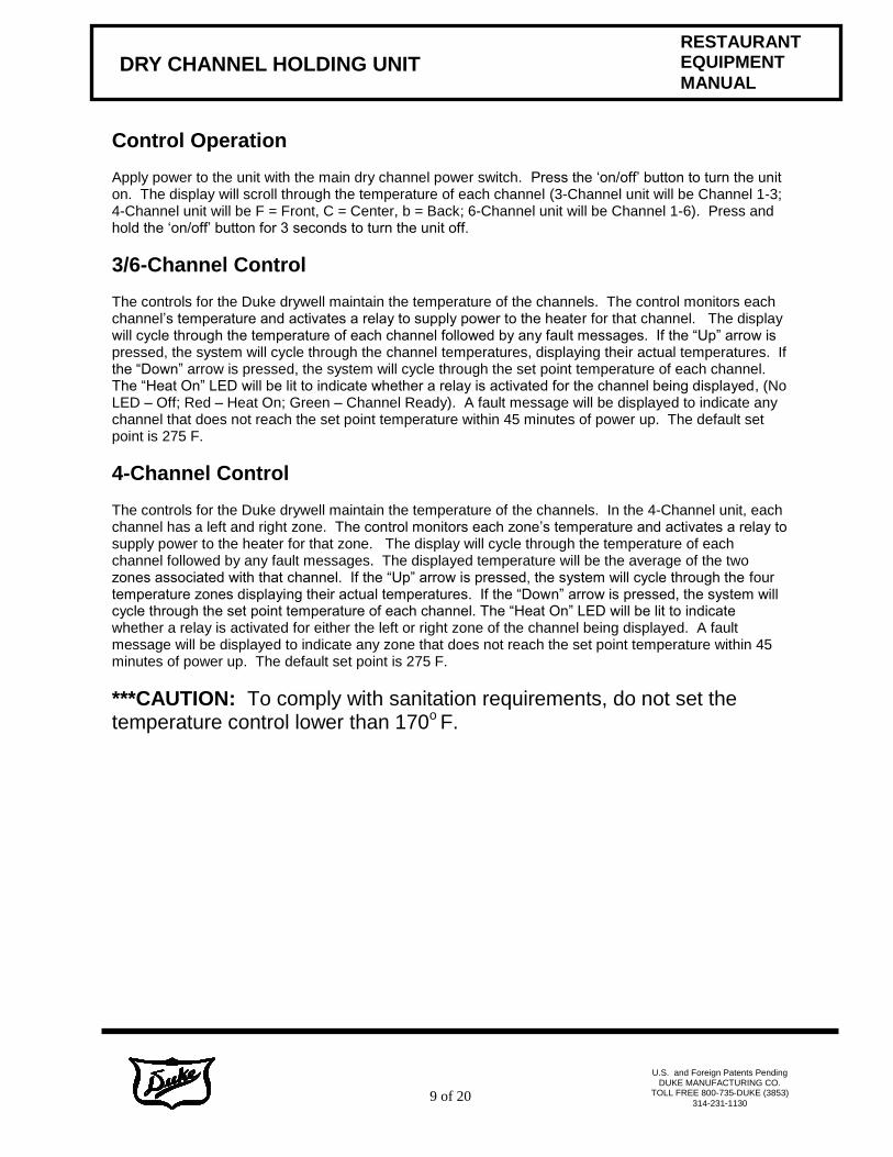
Control Operation
Apply power to the unit with the main dry channel power switch. Press the ‘on/off’ button to turn the unit on. The display will scroll through the temperature of each channel (3-Channel unit will be Channel 1-3; 4-Channel unit will be F = Front, C = Center, b = Back; 6-Channel unit will be Channel 1-6). Press and hold the ‘on/off’ button for 3 seconds to turn the unit off.
3/6-Channel Control The controls for the Duke drywell maintain the temperature of the channels. The control monitors each channel’s temperature and activates a relay to supply power to the heater for that channel. The display will cycle through the temperature of each channel followed by any fault messages. If the “Up” arrow is pressed, the system will cycle through the channel temperatures, displaying their actual temperatures. If the “Down” arrow is pressed, the system will cycle through the set point temperature of each channel. The “Heat On” LED will be lit to indicate whether a relay is activated for the channel being displayed, (No LED – Off; Red – Heat On; Green – Channel Ready). A fault message will be displayed to indicate any channel that does not reach the set point temperature within 45 minutes of power up. The default set point is 275 F.
4-Channel Control The controls for the Duke drywell maintain the temperature of the channels. In the 4-Channel unit, each channel has a left and right zone. The control monitors each zone’s temperature and activates a relay to supply power to the heater for that zone. The display will cycle through the temperature of each channel followed by any fault messages. The displayed temperature will be the average of the two zones associated with that channel. If the “Up” arrow is pressed, the system will cycle through the four temperature zones displaying their actual temperatures. If the “Down” arrow is pressed, the system will cycle through the set point temperature of each channel. The “Heat On” LED will be lit to indicate whether a relay is activated for either the left or right zone of the channel being displayed. A fault message will be displayed to indicate any zone that does not reach the set point temperature within 45 minutes of power up. The default set point is 275 F.
***CAUTION: To comply with sanitation requirements, do not set the temperature control lower than 170o F.

10 of 20
DRY CHANNEL HOLDING UNIT
RESTAURANT EQUIPMENT
MANUAL
U.S. and Foreign Patents Pending
DUKE MANUFACTURING CO. TOLL FREE 800-735-DUKE (3853)
314-231-1130
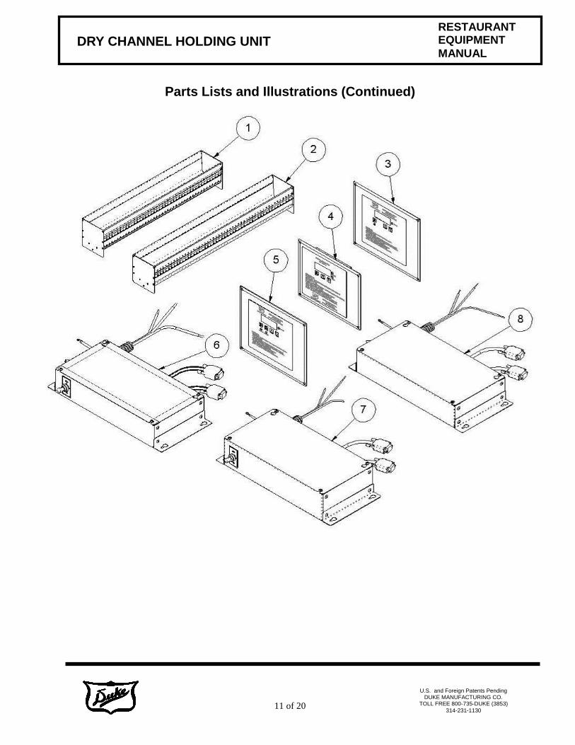
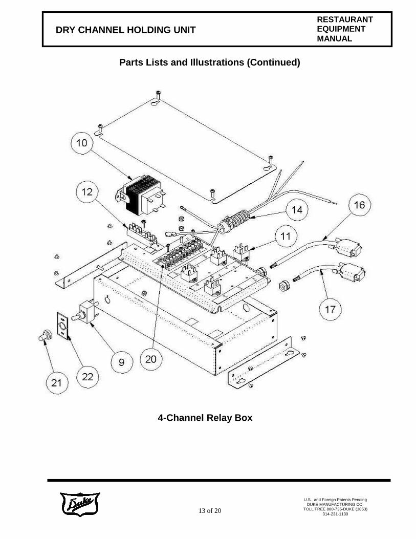
Parts Lists and Illustrations
Locator P/N Description HDC3-37.5 HDC4-44 HDC6-37.5
1 553509 Assy, Center Channel HDC-3/HDC-6 Replacement N/A N/A N/A
2 553291 Assy, Center Channel HDC-4 Replacement N/A N/A N/A
3 228888 Assy, Control Board Display 3-Channel 1 0 0
4 218880 Assy, Control Board Display 4-Channel 0 2 0
5 228881 Assy, Control Board Display 6-Channel 0 0 1
6 553443 Assy, Relay Box W/ Switch HDC-3 1 (GTO kit) 0 0
553289 Assy, Relay Box W/ Switch HDC-4 0 2 0
7 553444 Assy Relay Box W/ Switch HDC-6 0 0 1
8 553484 Assy, Relay Box W/O Switch 1 (Prod unit) 0 0
9 218963 Switch, Toggle NKK, Relay Box 1 2 1
10 218829 Transformer, 208/240P 24SE Tyco #3-1611450-4 1 2 1
11 218828 Relay, Mini NO 20A 280/24V 3 8 6
12 218805 Terminal Block, 2 Pole 1 2 0
13 228810 Terminal Block, 0 0 1
14 218946 Conduit, Assy Power Supply Relay Box 0 2 0
15 228882 Conduit, Assy Power Supply Relay Box 1 0 1
16 218918 Harness, HD15 for RTD’s 1 2 1
17 218917 Harness, DSUB9/Relays 0 2 0
18 228820 Harness, DSUB9/Relays 3-Channel 1 0 0
19 228822 Harness, DSUB9/Relays 6-Channel 0 0 1
20 218902 Terminal Block, Ideal 1 2 1
21 218964 Boot, Toggle Switch, Splash Proof 1 2 1
22 218965 Plate, On-Off 1 2 1
11 of 20
DRY CHANNEL HOLDING UNIT
RESTAURANT EQUIPMENT
MANUAL
U.S. and Foreign Patents Pending
DUKE MANUFACTURING CO. TOLL FREE 800-735-DUKE (3853)
314-231-1130
Parts Lists and Illustrations (Continued)

12 of 20
DRY CHANNEL HOLDING UNIT
RESTAURANT EQUIPMENT
MANUAL
U.S. and Foreign Patents Pending
DUKE MANUFACTURING CO. TOLL FREE 800-735-DUKE (3853)
314-231-1130
Parts Lists and Illustrations (Continued)
3-Channel Relay Box
13 of 20
DRY CHANNEL HOLDING UNIT
RESTAURANT EQUIPMENT
MANUAL
U.S. and Foreign Patents Pending
DUKE MANUFACTURING CO. TOLL FREE 800-735-DUKE (3853)
314-231-1130
Parts Lists and Illustrations (Continued)
4-Channel Relay Box

14 of 20
DRY CHANNEL HOLDING UNIT
RESTAURANT EQUIPMENT
MANUAL
U.S. and Foreign Patents Pending
DUKE MANUFACTURING CO. TOLL FREE 800-735-DUKE (3853)
314-231-1130
Parts Lists and Illustrations (Continued)
6-Channel Relay Box
15 of 20
DRY CHANNEL HOLDING UNIT
RESTAURANT EQUIPMENT
MANUAL
U.S. and Foreign Patents Pending
DUKE MANUFACTURING CO. TOLL FREE 800-735-DUKE (3853)
314-231-1130
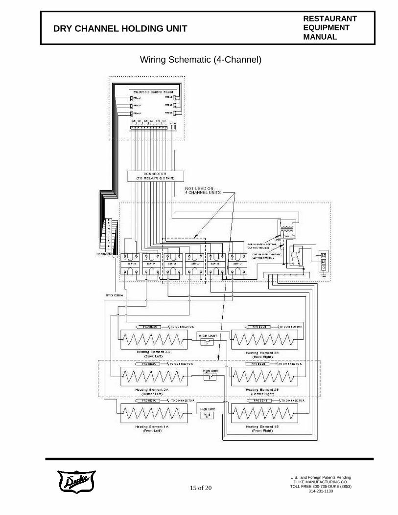
Wiring Schematic (4-Channel)
16 of 20
DRY CHANNEL HOLDING UNIT
RESTAURANT EQUIPMENT
MANUAL
U.S. and Foreign Patents Pending
DUKE MANUFACTURING CO. TOLL FREE 800-735-DUKE (3853)
314-231-1130
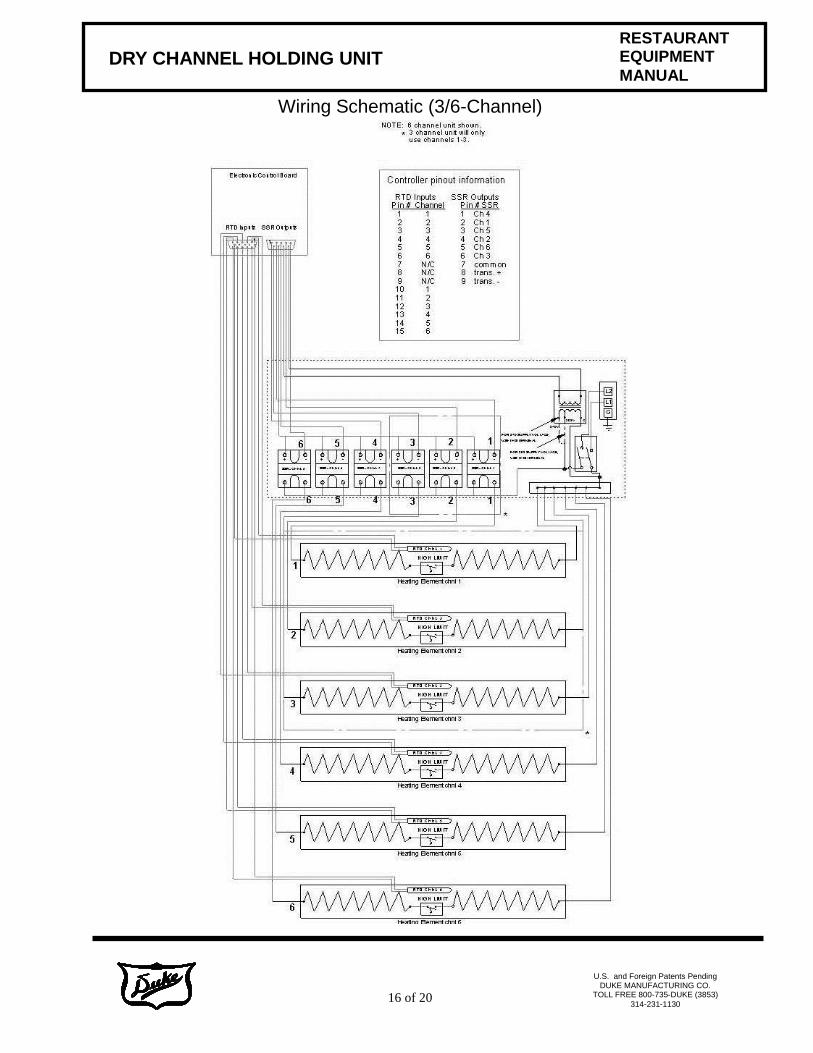
Wiring Schematic (3/6-Channel)

17 of 20
DRY CHANNEL HOLDING UNIT
RESTAURANT EQUIPMENT
MANUAL
U.S. and Foreign Patents Pending
DUKE MANUFACTURING CO. TOLL FREE 800-735-DUKE (3853)
314-231-1130
Wiring Layout for Relay Box Connection (3-Channel)
18 of 20
DRY CHANNEL HOLDING UNIT
RESTAURANT EQUIPMENT
MANUAL
U.S. and Foreign Patents Pending
DUKE MANUFACTURING CO. TOLL FREE 800-735-DUKE (3853)
314-231-1130
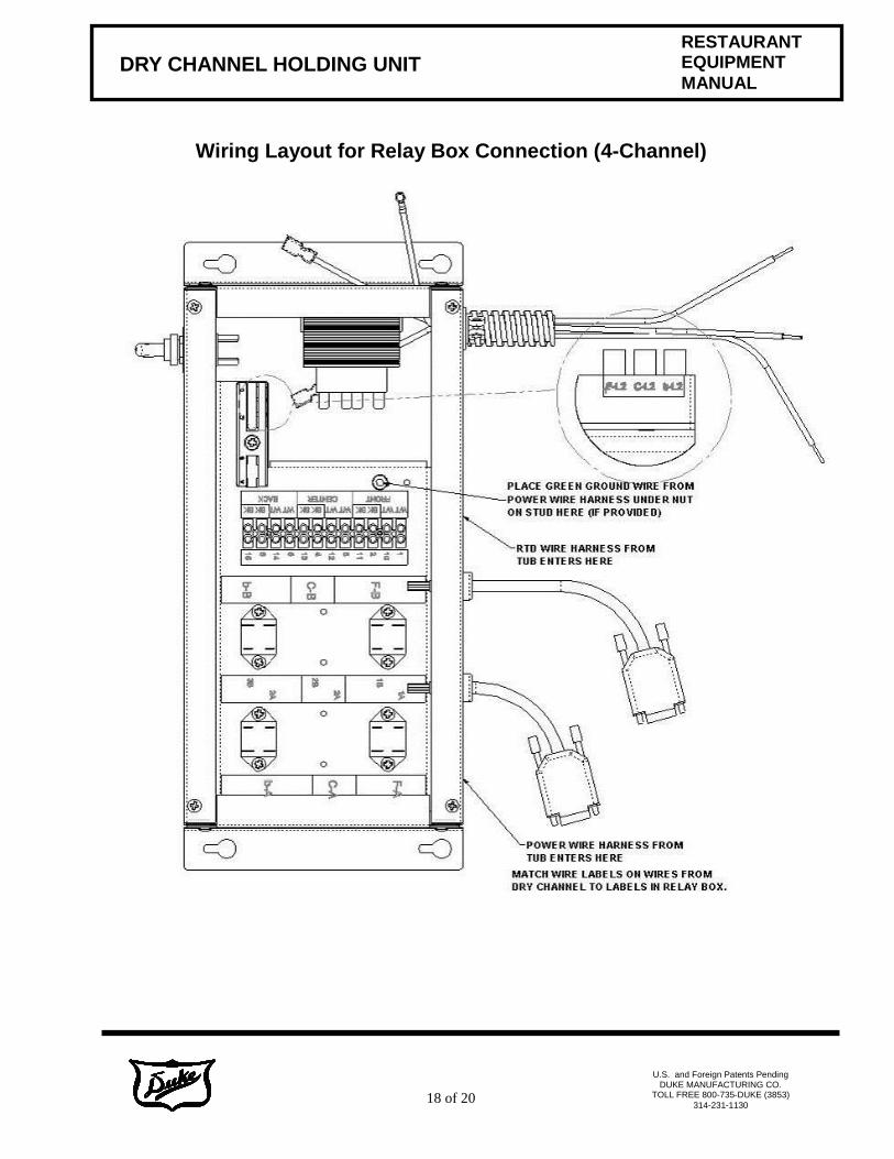
Wiring Layout for Relay Box Connection (4-Channel)
19 of 20
DRY CHANNEL HOLDING UNIT
RESTAURANT EQUIPMENT
MANUAL
U.S. and Foreign Patents Pending
DUKE MANUFACTURING CO. TOLL FREE 800-735-DUKE (3853)
314-231-1130
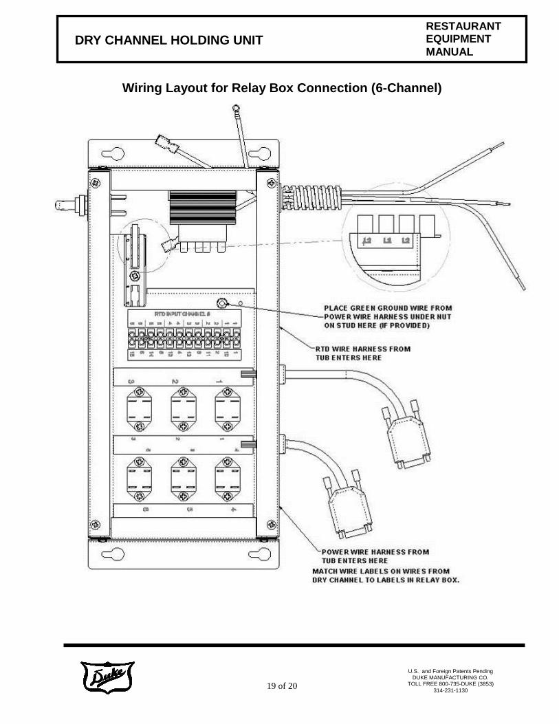
Wiring Layout for Relay Box Connection (6-Channel)
20 of 20
DRY CHANNEL HOLDING UNIT
RESTAURANT EQUIPMENT
MANUAL
U.S. and Foreign Patents Pending
DUKE MANUFACTURING CO. TOLL FREE 800-735-DUKE (3853)
314-231-1130
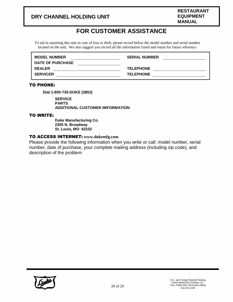
To aid in reporting this unit in case of loss or theft, please record below the model number and serial number
located on the unit. We also suggest you record all the information listed and retain for future reference.
TO PHONE:
Dial 1-800-735-DUKE (3853)
SERVICE PARTS ADDITIONAL CUSTOMER IMFORMATION
TO WRITE:
Duke Manufacturing Co. 2305 N. Broadway St. Louis, MO 63102
TO ACCESS INTERNET: www.dukemfg.com
Please provide the following information when you write or call: model number, serial number, date of purchase, your complete mailing address (including zip code), and description of the problem
MODEL NUMBER SERIAL NUMBER
DATE OF PURCHASE
DEALER TELEPHONE
SERVICER TELEPHONE
FOR CUSTOMER ASSISTANCE