Embed Size (px)
Citation preview

6175 5-29-14-7
800-456-7100 I www.paladinattachments.com 503 Gay Street, Delhi, IA 52223, United States of America Copyright ©
OPERATOR’S AND PARTS MANUAL
612 TRENCHER 3-POINT HITCH CAT. 1
SERIAL NUMBER: ___________________ Manual Number: OM521 Part Number: 75421 MODEL NUMBER: ___________________ Rev. 5


TABLE OF CONTENTS
6230 8-30-12-2
PREFACE ................................................................................................................................................................................3
SAFETY PRECAUTIONS SAFETY STATEMENTS ..............................................................................................................................................5 GENERAL SAFETY PRECAUTIONS ..................................................................................................................... 5-7 EQUIPMENT SAFETY PRECAUTIONS ................................................................................................................. 8-9
DECALS .......................................................................................................................................................................... 10-13
PREOPERATION HYDRAULICS ...........................................................................................................................................................14 PREPARING THE TRACTOR ...................................................................................................................................14 OPTIONS ............................................................................................................................................................ 14-15 NOMENCLATURE ....................................................................................................................................................16
INSTALLATION MOUNTING INSTRUCTIONS ............................................................................................................................. 17-19 WEIGHT AND BALANCE ..........................................................................................................................................19 POWER (PTO) SHAFT ADJUSTMENT ....................................................................................................................20
OPERATING INSTRUCTIONS CONTROLS ........................................................................................................................................................ 21-25 OPERATION ....................................................................................................................................................... 26-33
DIGGING CHAIN OPTIONS ........................................................................................................................................ 34-53
MAINTENANCE AND SERVICE LUBRICATION ..........................................................................................................................................................54 HYDRAULIC SYSTEM ..............................................................................................................................................55 DIGGING CHAIN REMOVAL .............................................................................................................................. 56-57 HEADSHAFT ASSEMBLY SERVICE ........................................................................................................................58 BOOM END IDLER REMOVAL .................................................................................................................................58 PTO DRIVE ASSEMBLY MAINTENANCE ...............................................................................................................59 DIGGING TOOTH REPLACEMENT .........................................................................................................................59 PTO DRIVE ASSEMBLY REPLACEMENT (FRICTION CLUTCH, SAFETY SHIELD, U-JOINT) ....................... 60-62 CYLINDER SEAL REPLACEMENT .................................................................................................................... 63-64
REMOVAL AND STORAGE ...............................................................................................................................65
TROUBLESHOOTING ...................................................................................................................................66-69
SPECIFICATIONS BOLT TORQUE SPECIFICATIONS ..........................................................................................................................70 612 TRENCHER SPECIFICATIONS ........................................................................................................................71
LIMITED WARRANTY ........................................................................................................................................................73
PARTS TRENCHER ASSEMBLY .................................................................................................................................... 74-79 GEAR BOX ASSEMBLY ..................................................................................................................................... 80-81 CYLINDER ASSEMBLY #60964 ......................................................................................................................... 82-83 PTO DRIVE ASSEMBLY ..................................................................................................................................... 84-85 30" CRUMBER ASSEMBLY #110631 - SN #204939 AND UP ........................................................................... 86-87 30" CRUMBER ASSEMBLY SERVICE PARTS - UP TO SN #204938 ............................................................... 88-89 36" CRUMBER ASSEMBLY #110632 - SN #204939 AND UP ........................................................................... 90-91 36" CRUMBER ASSEMBLY SERVICE PARTS - UP TO SN #204938 ............................................................... 92-93 48" CRUMBER ASSEMBLY #110633 - SN #204939 AND UP ........................................................................... 94-95 48" CRUMBER ASSEMBLY SERVICE PARTS - UP TO SN #204938 ............................................................... 96-97 60" CRUMBER ASSEMBLY #110634 - SN #204939 AND UP ........................................................................... 98-99 60" CRUMBER ASSEMBLY SERVICE PARTS - UP TO SN #204938 ........................................................... 100-101 HEADSHAFT CARTRIDGE ASSEMBLY #60001 ........................................................................................... 102-103 SPROCKET AND BOOM END SET ............................................................................................................... 104-105 20" AUGER ASSEMBLY #59000 .................................................................................................................... 106-107
75421 1

THIS PAGEIS INTENTIONALLY
BLANK
2 75421

PREFACE
10344 5-7-12-3
GENERAL COMMENTS Congratulations on the purchase of your new BRADCO product! This product was carefully designed and manufactured to give you many years of dependable service. Only minor mainte-nance (such as cleaning and lubricating) is required to keep it in top working condition. Be sure to observe all maintenance procedures and safety precautions in this manual and on any safety decals located on the product and on any equipment on which the attachment is mounted. This manual has been designed to help you do a better, safer job. Read this manual care-fully and become familiar with its contents.
WARNING! Never let anyone operate this unit without reading the "Safety Precautions" and "Operating Instructions" sections of this manual.
Always choose hard, level ground to park the vehicle on and set the brake so the unit cannot roll.
Unless noted otherwise, right and left sides are determined from the operator’s control posi-tion when facing the attachment.
NOTE: The illustrations and data used in this manual were current (according to the infor-mation available to us) at the time of printing, however, we reserve the right to redesign and change the attachment as may be necessary without notification.
BEFORE OPERATION The primary responsibility for safety with this equipment falls to the operator. Make sure the equipment is operated only by trained individuals that have read and understand this manual. If there is any portion of this manual or function you do not understand, contact your local authorized dealer or the manufacturer to obtain further assistance. Keep this manual available for reference. Provide the manual to any new owners and/or operators.
SAFETY ALERT SYMBOLThis is the “Safety Alert Symbol” used by this industry. This symbol is used to warn of possible injury. Be sure to read all warnings carefully. They are included for your safety and for the safety of others working with you.
SERVICE Use only manufacturer replacement parts. Substitute parts may not meet the required stan-dards. Record the model and serial number of your unit on the cover of this manual. The parts department needs this information to insure that you receive the correct parts.
SOUND AND VIBRATIONSound pressure levels and vibration data for this attachment are influenced by many different param-eters: some items are listed below (not inclusive):
• prime mover type, age, condition, with or without cab enclosure and configuration• operator training, behavior, stress level• job site organization, working material condition, environment
Based on the uncertainty of the prime mover, operator, and job site, it is not possible to get precise ma-chine and operator sound pressure levels or vibration levels for this attachment.
NOTE: A list of all Paladin Patents can be found at http//www.paladinbrands.com/patents.asp.
75421 3

THIS PAGEIS INTENTIONALLY
BLANK
4 75421

10338 8-16-05
SAFETY STATEMENTS
DANGER
GENERAL SAFETY PRECAUTIONS
WARNING! READ MANUAL PRIOR TO INSTALLATIONImproper installation, operation, or maintenance of this equipment could result in serious injury or death. Operators and maintenance personnel should read this man-ual, as well as all manuals related to this equipment and the prime mover thoroughly before beginning installation, operation, or maintenance. FOLLOW ALL SAFETY INSTRUCTIONS IN THIS MANUAL AND THE PRIME MOVER’S MANUAL(S).
READ AND UNDERSTAND ALL SAFETY STATEMENTSRead all safety decals and safety statements in all manuals prior to operating or working on this equipment. Know and obey all OSHA regulations, local laws, and other professional guidelines for your operation. Know and follow good work practices when assembling, maintaining, repairing, mounting, removing, or operating this equipment.
KNOW YOUR EQUIPMENTKnow your equipment’s capabilities, dimensions, and operations before operating. Visually inspect your equipment before you start, and never operate equipment that is not in proper working order with all safety devices intact. Check all hardware to ensure it is tight. Make certain that all locking pins, latches, and connection devices are properly installed and secured. Remove and replace any damaged, fatigued, or excessively worn parts. Make certain all safety decals are in place and are legible. Keep decals clean, and replace them if they become worn or hard to read.
WARNING
CAUTION
THIS SIGNAL WORD IS USED WHERE SERIOUS INJURY OR DEATHWILL RESULT IF THE INSTRUCTIONS ARE NOT FOLLOWED PROPERLY.
THIS SIGNAL WORD IS USED WHERE SERIOUS INJURY OR DEATHCOULD RESULT IF THE INSTRUCTIONS ARE NOT FOLLOWED PROPERLY.
THIS SIGNAL WORD IS USED WHERE MINOR INJURY COULD RESULT IF THE INSTRUCTIONS ARE NOT FOLLOWED PROPERLY.
NOTICE INDICATES A PROPERTY DAMAGE MESSAGE. NOTICE
THIS SYMBOL BY ITSELF OR WITH A WARNING WORD THROUGHOUT THIS MAN-UAL IS USED TO CALL YOUR ATTENTION TO INSTRUCTIONS INVOLVING YOUR PERSONAL SAFETY OR THE SAFETY OF OTHERS. FAILURE TO FOLLOW THESE INSTRUCTIONS CAN RESULT IN INJURY OR DEATH.
75421 5

GENERAL SAFETY PRECAUTIONS
WARNING! PROTECT AGAINST FLYING DEBRISAlways wear proper safety glasses, goggles, or a face shield when driving pins in or out, or when any operation causes dust, flying debris, or any other hazardous mate-rial.
WARNING! LOWER OR SUPPORT RAISED EQUIPMENTDo not work under raised booms without supporting them. Do not use support mate-rial made of concrete blocks, logs, buckets, barrels, or any other material that could suddenly collapse or shift positions. Make sure support material is solid, not de-cayed, warped, twisted, or tapered. Lower booms to ground level or on blocks. Lower booms and attachments to the ground before leaving the cab or operator’s station.
WARNING! USE CARE WITH HYDRAULIC FLUID PRESSUREHydraulic fluid under pressure can penetrate the skin and cause serious injury or death. Hydraulic leaks under pressure may not be visible. Before connecting or dis-connecting hydraulic hoses, read your prime mover’s operator’s manual for detailed instructions on connecting and disconnecting hydraulic hoses or fittings.
• Keep unprotected body parts, such as face, eyes, and arms as far away as possible from a suspected leak. Flesh injected with hydraulic fluid may develop gangrene or other permanent disabilities.
• If injured by injected fluid, see a doctor at once. If your doctor is not familiar with this type of injury, ask him to research it immediately to determine proper treat-ment.
• Wear safety glasses, protective clothing, and use a piece of cardboard or wood when searching for hydraulic leaks. DO NOT USE YOUR HANDS!
SEE ILLUSTRATION.
CARDBOARD
HYDRAULIC HOSEOR FITTING
MAGNIFYING GLASS
10339 8-16-05
6 75421

GENERAL SAFETY PRECAUTIONS
10340 8-16-05
WARNING! DO NOT MODIFY MACHINE OR ATTACHMENTSModifications may weaken the integrity of the attachment and may impair the func-tion, safety, life, and performance of the attachment. When making repairs, use only the manufacturer’s genuine parts, following authorized instructions. Other parts may be substandard in fit and quality. Never modify any ROPS (Roll Over Protection Structure) or FOPS (Falling Object Protective Structure) equipment or device. Any modifications must be authorized in writing by the manufacturer.
WARNING! SAFELY MAINTAIN AND REPAIR EQUIPMENT• Do not wear loose clothing or any accessories that can catch in moving parts. If
you have long hair, cover or secure it so that it does not become entangled in the equipment.
• Work on a level surface in a well-lit area.• Use properly grounded electrical outlets and tools.• Use the correct tools for the job at hand. Make sure they are in good condition for
the task required.• Wear the protective equipment specified by the tool manufacturer.
SAFELY OPERATE EQUIPMENTDo not operate equipment until you are completely trained by a qualified operator in how to use the controls, know its capabilities, dimensions, and all safety require-ments. See your machine’s manual for these instructions.• Keep all step plates, grab bars, pedals, and controls free of dirt, grease, debris,
and oil.• Never allow anyone to be around the equipment when it is operating.• Do not allow riders on the attachment or the prime mover.• Do not operate the equipment from anywhere other than the correct operator’s
position. • Never leave equipment unattended with the engine running, or with this attach-
ment in a raised position.• Do not alter or remove any safety feature from the prime mover or this attach-
ment.• Know your work site safety rules as well as traffic rules and flow. When in doubt
on any safety issue, contact your supervisor or safety coordinator for an explana-tion.
75421 7

11103 5-16-08
EQUIPMENT SAFETY PRECAUTIONS
WARNING! KNOW WHERE UTILITIES AREObserve overhead electrical and other utility lines. Be sure equipment will clear them. When digging, call your local utilities for location of buried utility lines, gas, water, and sewer, as well as any other hazard you may encounter.
WARNING! EXPOSURE TO RESPIRABLE CRYSTALLINE SILICA DUST ALONG WITH OTHER HAZARDOUS DUSTS MAY CAUSE SE-RIOUS OR FATAL RESPIRATORY DISEASE.It is recommended to use dust suppression, dust collection and if necessary person-al protective equipment during the operation of any attachment that may cause high levels of dust.
WARNING! REMOVE PAINT BEFORE WELDING OR HEATINGHazardous fumes/dust can be generated when paint is heated by welding, soldering or using a torch. Do all work outside or in a well ventilated area and dispose of paint and solvent properly. Remove paint before welding or heating.
When sanding or grinding paint, avoid breathing the dust. Wear an approved respira-tor. If you use solvent or paint stripper, remove stripper with soap and water before welding. Remove solvent or paint stripper containers and other flammable material from area. Allow fumes to disperse at least 15 minutes before welding or heating.
OPERATING THE TRENCHERPTO Operated Attachment: Rotating driveline contact can cause death. Do not oper-ate without all driveline, tractor and equipment shields in place. Drivelines securely attached at both ends. Driveline shields that turn freely on drivelineBlock off work area from bystanders, livestock, etc. Stop operation if bystanders or livestock enter the work area.Operate only from the operator’s station.Never drop a boom with a rapidly moving digging chain on the ground. The force of the trencher may cause the vehicle to move suddenly and unexpectedly.Use caution when operating on slopes. The natural vibration will cause the unit to creep sideways downhill. Try to dig with trencher in a level position.Do not adjust relief valve settings. Incorrect valve settings could result in equipment damage and/or personal injury.An operator must not use drugs or alcohol, which can change his or her alertness or coordination. An operator taking prescription or over-the-counter drugs should seek medical advice on whether or not he or she can safely operate equipment.Before exiting the prime mover, lower the unit to the ground, turn off the prime mover’s engine, remove the key and apply the brakes.Do not use the trencher crumber bar or chain as a step when climbing in or out of the prime mover. Be alert to changes in the work area. Watch out for bystanders, changes in weather and soil conditions.Do not make sharp turns while trenching. Trencher could become wedged in the trench and damaged.Keep equipment and bystanders away from the trencher after it has been dug. The weight could cause a cave in.If chain becomes jammed, never attempt to free it while the unit is running. Stop the unit, shut off the engine and review the situation.
•
•
••
•
•
•
•
•
•
•
•
•
8 75421

TRANSPORTING THE TRENCHERWhen driving on public roads use safety lights, reflectors, Slow Moving Vehicle signs etc., to prevent accidents. Check local government regulations that may affect you.Do not drive close to ditches, excavations, etc., cave in could result.Do not smoke when refueling the prime mover. Allow room in the fuel tank for expansion. Wipe up any spilled fuel. Secure cap tightly when done.When transporting keep the trencher as low as the terrain will allow.
MAINTAINING THE TRENCHERBefore performing maintenance, lower the attachment to the ground, turn off the engine, remove the key and apply the brakes.Never perform any work on the attachment unless you are authorized and quali-fied to do so. Always read the operator service manuals before any repair is made. After completing maintenance or repair, check for correct functioning of the backhoe. If not functioning properly, always tag “DO NOT OPERATE” until all problems are corrected.Worn, damaged, or illegible safety decals must be replaced. New safety decals can be ordered from BRADCO.Never make hydraulic repairs while the system is under pressure. Serious personal injury or death could result.Never work under a raised attachment.Replace all safety shields and guards when done performing maintenance. Do not operate trencher with protective equipment removed.
•
••
•
•
•
•
•
••
EQUIPMENT SAFETY PRECAUTIONS
11104 5-16-08
75421 9

DECAL PLACEMENT
4285
4105
4498
40157
40092
4494
4495
4084
4286
40158 4338
4132
4291
4350
40157
40092
4084
401614056
6245 8-28-12-2
GENERAL INFORMATION The following diagrams show the location of all the decals used on your attachment. The decals are identified by their part numbers, with the reductions of the actual deals shown on the following pages. Use this information to order replacements for lost or damaged decals. Be sure to read all decals before operating the attachment. They contain information you need to know for both safety and attachment longevity.
IMPORTANT: Keep all safety decals clean and legible. Replace all missing, illegible or damaged safety decals. When replacing parts with safety decals attached, the safety decals must also be replaced.
REPLACING SAFETY DECALS: Clean the area of application with a nonflammable solvent, then wash the same area with soap and water. Allow the surface to dry. Remove the backing from the safety decal, exposing the adhe-sive surface. Apply the safety decal to the position shown in the diagram, and smooth out any bubbles.
10 75421

DECALS
6246 8-28-12-3
MODEL NUMBER DECALPART #40157
BRADCO LOGOPART #40092
BOOM CONTROLPART #40158
DANGER! ROTATING DRIVELINEPART #4286(LOCATED ON PTO)
DANGER! SHIELD MISSINGPART #4285(LOCATED ON INSIDE PTO SHAFT)
612
DOWN
UP
BOOM CONTROL
#40158
BRADCO612
TRENCHER
75421 11

DECALS
6247 8-28-12-3
QUICK COUPLER HOOK-UPPART #4291
WARNINGPART #4495
OPERATOR'S WARNINGPART #4494
TOOTH SET-UP WARNINGPART #4056
12 75421

DECALS
6248 8-28-12-3
STAND CLEAR
STAND CLEAR
DANGERDANGER STAND CLEARPART #4105
CHECK OIL LEVELPART #4132
MADE IN USAPART #4338
DANGER STAND CLEARPART #4498
STAND CLEARPART #40161
GREASE 8 HOURSPART #4084
75421 13

PREOPERATION612 TRENCHER
GENERAL INFORMATION
The 612 trencher mounts directly to the 3-point hitch system on your tractor the same as any other 3-point hitch attachment.
HYDRAULICS
The 612 trenchers are shipped with two 50" long hoses for connecting to your tractor's rear remote hydraulic system. Contact your local dealer to purchase adapters and couplers to match up to your tractor's hydraulic system.
PREPARING THE TRACTOR
Bradco 612 trenchers are used on 3-point hitch (Category 1) hydrostatic tractors. Re-mote hydraulics between 4 and 7 GPM flow and a minimum working pressure of 1800/2250 PSI, 540 RPM, and rear PTO drive are also required.
A front counterweight (such as a loader or dozer blade) may be necessary to proper transportation and operation of the tractor and trencher. A minimum of 20% of the gross ve-hicle weight must be on the tractor's front axle. (See "Weight and Balance" in the Installation section of this manual.)
OPTIONS
Eventually you may wish to dig a trencher of a depth or width other than what your unit was originally equipped to dig. The trencher can be fitted with optional booms, digging chains, sprockets, and crumber assemblies to allow you to dig a variety of different sized trenches. The chart on the following page will give you an idea of the different trench depths and widths a properly equipped unit is capable of digging. For more detailed information on trencher op-tions see Digging Chain Options section of this manual.
6227 8-29-12-2
14 75421

PREOPERATION612 TRENCHER
30" Depth 4.25" 6.00" 8.00" 10.00" 12.00" 36" Depth 4.25" 6.00" 8.00" 10.00" ------- 48" Depth 4.25" 6.00" 8.00" ------- ------- 60" Depth 4.25" 6.00" ------- ------- -------
* Trencher depths are given with the digging boom at an optimum 65° digging angle and the auger touching the ground. Trenches of various depths can be made by varying the digging angle and rais-ing the trencher up higher. These methods are less efficient how-ever.
NOTE: The illustrations and data used in this manual were current (according to the infor-mation available to us) at the time of printing, however, we reserve the right to redesign and change the trenchers as may be necessary without notification.
TRENCH DEPTHS * TRENCH WIDTHS
6228 8-29-12-275421 15

GENERAL INFORMATION
The purpose of this page is to acquaint you with the 3-point hitch system, the tren-cher, and the names of the various components. This knowledge will be helpful when read-ing through this manual or when ordering service parts. (NOTE: Crumber Ends have been changed on trenchers with SN#204939 and UP.)
ROCKSHAFT
LIFT LINKAGE
ANTI-SWAY CHAINLOWER LINKS
TRACTOR 3-POINT HITCH SYSTEM COMONENTS
LOWER HITCH POINT
LEVELING LIFT LINKAGE
LIFT ARM
TOP LINK
UPPER HITCH POINT
612 TRENCHERSYSTEM COMPONENTS MAINFRAME
CRUMBER BAR/PERSONAL RESTRAINT BAR
CRUMBER BOOM ADJUSTMENT
CRUMBER END
CRUMBER SHOE
HEADSHAFT AUGER
DIGGING BOOM
DIGGING TOOTH
WEAR STRIP
BOOM END IDLER
PIVOT CYLINDER
GEARBOX
6229 8-29-12-2
PREOPERATION612 TRENCHER
MAJOR COMPONENT NOMENCLATURE
16 75421

6223 6-11-15-3
INSTALLATION
GENERAL INFORMATION The following instructions will help you to mount the trencher onto your tractor. The trencher uses the 3-point hitch system for ease of installation, therefore if you have ever in-stalled 3-point hitch equipment before, installing the trencher should prove no problem. Your tractor must be equipped with rear remote auxiliary hydraulics for trencher opera-tion. Prior to installing the trencher you must install the appropriate hydraulic couplers onto the trencher hoses for your application. Remember to read all safety warnings, decals, and oper-ating instructions before operating the tractor or trencher.
IMPORTANT: A front counterweight may be necessary for proper transportation and op-eration of the tractor and trencher. A minimum of 20% of the gross vehicle weight must be on the tractor's front axle. (Refer to the information on Weight and Balance at the end of this section.)
MOUNTING INSTRUCTIONS1. If you have not done so already, remove the steel shipping banding from around the
trencher and skid.2. Install the PTO drive assembly to the trencher by installing the key #5661 in the input
shaft #89331 of the trencher gear box and sliding the clutch end of the PTO drive as-sembly onto the shaft. Secure drive assembly to input shaft with set screw.
3. Following the proper start up and backing procedures as noted in your tractor operator's manual, back the tractor up to the rear of the trencher and skid.
4. Adjust the tractor's 3-point hitch system to accept the trencher. Continue backing the tractor up to the trencher and then attach the trencher by positioning the lower links onto the trencher's hitch pins. Secure with klik pins #57496.
NOTE: Since the trencher is fairly heavy, we recommend you position the lift links of the lower links in the position offering the greatest lift capabilities. If there is more than one hole in the lower link, position the lift link in the rear most hole.
5. Position the top link of the tractor in place between the ears of the gear box assemblies top linkage.. Use the mounting hole in the linkage that will allow ALL THREE 3-POINT LINKS TO RUN PARALLEL. Secure the top link using the hitch pin #82963 and klik pin #21169 provided. Adjust the top link so the 3-POINT MOUNTING BRACKET REMAINS VERTICAL, (perpendicular to the ground). See Figure #1
FIGURE #1
Okay for digging. Okay for transport. Too much Too low. Too much bend for PTO operation. bend for PTO operation.
6. Adjust the lower link anti-sway chains and center the trencher.7. Complete the hydraulic plumbing by connecting the hydraulic couplers together.
75421 17

INSTALLATION
6224 8-29-12-2
NOTE: The auxiliary hydraulics on your tractor operates the trencher cylinder and is used to lower the trencher into the ground or raise it up for transport.
WARNING! Escapingfluidunderpressurecanhavesufficientforcetopenetratetheskin causing serious personal injury. Fluid escaping from a very small hole can be almost invisible. Use a piece of cardboard or wood, rather than hands to search for suspected leaks.
Keep unprotected body parts, such as face, eyes, and arms as far away as possiblefromasuspectedleak.Fleshinjectedwithhydraulicfluidmaydevelop gangrene or other permanent disabilities.
Ifinjuredbyinjectedfluid,seeadoctoratonce.Ifyourdoctorisnotfamil-iar with this type of injury, ask him to research it immediately to determine proper treatment.
NOTE: When connecting trencher to tractor, route the hydraulic hoses as far away as possible from the operator. Also use care to route away from sharp corners and from dragging on the ground. (When disconnecting trencher from tractor either plug, cap or connect hose ends to keep system free from contaminants and store hoses off the ground.)
8. With the hydraulics hooked up, raise the trencher and remove the skid. 9. Lower the trencher to the ground. Disconnect the top link from the tractor and tilt the
trencher away from the tractor. (It may also be necessary to raise the trencher into the extreme UP position to gain sufficient clearance to connect PTO drive assembly to trac-tor.)
10. Turn the tractor engine off and set the parking brake.
NOTE: To protect PTO shaft and operator, the up travel must be limited to keep at least 3" of the two halves of the PTO shaft together. To assist the operator in maintaining this limitation measure in 3" from the telescopic tube on the trencher half of the PTO shield and make a permanent mark around the diameter. (Refer to PTO shaft adjustment.)
11. Connect the PTO drive assembly to the tractor.12. Attach PTO shield and safety chains as shown in Figure #2.FIGURE #2 CAUTION! Always install PTO drive guard safety chains
before operating trencher.
Safety chains are used to hold the PTO drive guard from spinning. There are two chains to hold both halves of the PTO drive.
To mount chains:A. Wrap chain around left 3-point hitch arm and clip it back to
it leaving some slack for free movement when raising and lowering trencher.
B. It may be necessary if the chain is too short to clip the chain to a loop on the side of the 3-point arm. Care should be taken not to have too much loop in the chain so it does not wrap around the PTO drive when it is rotating.
A
B
18 75421

INSTALLATION
6225 8-29-12-2
13. Adjust 3-point lever upper stop to limit the travel to a point where trencher will clear the ground sufficient for transport and still keep at least 3" of shaft telescoped together.
14. Start the tractor and raise the trencher boom UP. Operate the 3-point hitch lifts to de-termine if its capacity is sufficient and all points work properly. Observe hydraulic hoses for correct routing as 3-point moves up and down. Adjust tractor (see tractor operator's manual) to limit rate of drop of 3-point to a safe speed.
Trencher installation is now complete. Read all safety warnings, decals, and operating instruc-tions before operating the trencher.
WEIGHT AND BALANCE After you have completed the mounting procedures, a very important item to complete before releasing for use is weight distribution for steering control. Tractor front attachments such as a loader or blade may be sufficient, however, you must know. Industry recommended practice states that 20% of the gross vehicle weight should remain on the front axle during transport conditions. To perform this check, weigh the entire machine with attachments, both front and rear in transport position. Record results. Next weigh each axle separately and record results.
Example A: GVW 2650 lbs Front 600 lbs Rear 2050 lbs
2650 X 20% = 530 lbs - recommended front axle weight
You have 600 lbs which exceeds the 530 necessary to meet industry recommended practice.
Example B: GVW 3275 lbs Front 595 lbs Rear 2860 lbs
3275 X 20% = 655 lbs - recommended front axle weight
You have 595 which is 60 lbs less than the recommended 655 lbs. You will need to add 75 lbs to the front axle to attain the industry recommended practice weight distribution.This is calculated as follows: Old GVW = 3275 lbs New GVW add 75 lbs = 3350 3350 X 20% = 670 lbs - recommended front axle weight You may use weights or tire ballast to accomplish you goal.
75421 19

TRENCHER INSTALLATION612 TRENCHER
There should be a minimum of .25" of free travel before the shaft is fully retracted. To check: a. Lower the trencher until the shaft is parallel to the ground and is
straight inline with the trencher gearbox. b. Detach the shaft at the tractor and pull back to see if there is a mini-
mum of .25" free travel.
If there is not at least .25" of free travel the shaft must be shortened.
CAUTION FAILURE TO HAVE THE REQUIRED DISTANCE OF CLEARANCE WILL DAM-AGE THE POWER TAKE OFF (PTO) OF YOUR TRACTOR.
TO SHORTEN THE POWER SHAFT:
CUT EQUAL AMOUNTS OFF OF EACH SHAFT HALF TO ACQUIRE A MINIMUM OF .25" OF FREE TRAVEL WHEN
THE SHAFT IS FULLY RETRACTED.
7539 8-29-12-2
.25" FULLY RETRACTED
TRACTOR PTO
TRENCHER GEAR-BOX
TRACTOR
POWER (PTO) SHAFT ADJUSTMENT Thepower(PTO)shaftassemblymayneedtobeshortenedtofituptoyourtractorcor-rectly. The shaft assembly is shortest when the trencher is engaged into the ground and the shaft is straight inline with the trencher gearbox.
20 75421

OPERATING INSTRUCTIONSCONTROLS
612 TRENCHER
GENERAL INFORMATION Simplicity of operation is one of the key features of the 612 trencher. There is only one control on the trencher itself, and just a few adjustments to check. It is important however to be familiar with, and know the controls and adjustments on both the trencher and the tractor. Such knowledge is crucial for safe, efficient operation of equipment. Take the time to learn how they operate now.
THE TRACTOR Your trencher mount to the 3-point hitch system of the tractor. Due to this arrangement, thorough knowledge of the tractor and hitch controls is necessary for trencher operation. Read your tractor owner's manual for information regarding tractor operation before attempting to use the trencher.
RAISING / LOWERING THE TRENCHER Raise / lower the trencher unit by raising / lowering the tractor 3-point hitch arms through their appropriate tractor controls.
CAUTION! Become aware of any overhead power or telephone lines, tree limbs, etc. that the raised trencher could come into contact with. Contact with electri-cal lines could cause electrocution and death.
TILTING THE TRENCHER Tilt the trencher unit up or down by operating the rear auxiliary hydraulic controls locat-ed on the tractor to activate the trencher cylinder. See Figure #1
FIGURE #1
6232 8-29-12-2
CONTROL VALVE DECAL
STARTING AND STOPPING THE TRENCHER Power to the trencher is supplied by the tractor's PTO. Power is transferred from the PTO shaft, through the trencher's PTO drive shaft, through the trencher's PTO drive shaft and gear box, and finally to the trencher's auger, drive sprocket, and digging chain. Start the dig-ging chain by engaging the tractor PTO. Stop the digging chain by disengaging the tractor PTO.
75421 21

6233 8-29-12-2
TRENCHER SPEED CONTROL Again it may be noted that power to the trencher is supplied by the tractor PTO. To increase trencher speed, increase the tractor PTO shaft speed. To decrease trencher speed, decrease PTO speed.
AUGER HEIGHT The auger is fixed to the trencher mainframe and has no separate adjustment. To raise the auger, raise the trencher as previously described. This will raise the auger and thus leave the dirt or spoil closer to the trench.
Lowering the trencher will cause the auger to lower, moving the spoil away from the trench. The auger should NOT be lowered to the extent that the auger itself starts to dig in the ground. This will greatly reduce efficiency.
It should be noted that raising or lowering the trencher to change the auger height will also change the trencher depth. You will need to compensate for this by changing the tilt of the trencher down or up accordingly. See Figure #2
FIGURE #2
TRENCHER
AUGER
SPOIL
SPOIL
AUGER
OPERATING INSTRUCTIONSCONTROLS
612 TRENCHER
22 75421

CRUMBER SHOE / BAR ADJUSTMENT The purpose of the crumber shoe is to keep any loose dirt in the trencher close enough to the digging chain so that the digging teeth can grab it and remove it. This will give you a cleaner finished trench. Your trencher has an adjustable crumber bar / restraint bar that can be lengthened or shortened to bring the crumber shoe closer to or farther away from the digging chain. To adjust the crumber bar length, loosen the two jam nuts found at the end of the main-frame crumber bar tube. With the jam nuts loose, loosen the set screws on the tube. Slide the bar in or out to achieve the desired spacing (we suggest a distance of about 4" between crum-ber shoe and digging teeth for best overall results). Tighten the set screws and jam nuts when finished. See Figure #3
FIGURE #3
CHAIN TENSION ADJUSTMENT Chain tension is maintained by a large spring located inside the boom and adjusted by moving the boom in or out of the boom clamp plates located at the trencher end of the boom.
On the shorter booms (30" & 36") loosen the four clamp plate bolts. Tighten the chain by using a prying action over the pivot rod, located on the boom clamp plate, and through the holes in the side of the boom with a large punch, until the boom end is approximately 1.25" - 1.38" from the boom tube. Tighten the four clamp plate bolts to secure boom in place. Torque to 80 ft. lbs. See Figure #4
6234 8-29-12-2
JAM NUT
BAR / PERSONAL RESTRAINT BAR
MAINFRAME CRUMBER BAR TUBE
SET SCREWCRUMBER
OPERATING INSTRUCTIONSCONTROLS
612 TRENCHER
75421 23

FIGURE #4
(DIGGING CHAIN NOT SHOWN FOR CLARITY)
CLAMP BOLTS
TRENCHER MAINFRAME
PIVOT ROD
LARGE PUNCH
BOOM TUBE
BOOM END
BOOM CLAMP PLATES
1.25" - 1.38"
For the longer booms (48" & 60") a chain tightener kit is included in the boom assem-blies. To tighten chain loosen the four clamp plate bolts. Turn the adjusting nut clockwise until proper tension is obtained, the boom end should be approximately 1.25" - 1.38" from the boom tube. Tighten the four clamp plate bolts to secure boom in place. Torque to 80 ft. lbs. See Figure #5
FIGURE #5 BOOM CLAMP PLATES
CLAMP BOLTS
ADJUSTING STUD BOLTS
TRENCHER MAINFRAME
GUIDE TUBE
ADJUSTING NUT
ADJUSTING STUD
BOOM TUBE
BOOM END
1.25" - 1.38"
(DIGGING CHAIN NOT SHOWN FOR CLARITY)
6235 8-29-12-2
OPERATING INSTRUCTIONSCONTROLS
612 TRENCHER
24 75421

If the adjusting stud is too short to obtain proper chain tension tighten the four clamp plate bolts. Remove the two adjusting stub bolts which hold the adjusting stud in place. Repo-sition the adjusting stud to a position closer to the guide tube. Reinstall the adjusting stud bolts and then repeat the original procedure until proper tension is obtained.
If chain runs off in rocky ground or large roots, tighten further. Chain tension is impor-tant to monitor since excessive tension will cause high wear rates on the chain and sprockets and less than enough tension will cause run off problems.
CAUTION! Never work on, or make adjustments to any part of the trencher while the unit is running. You could get caught in the digging teeth and be severely injured or killed.
It is common for your trencher to need it's digging chain tightened after the first 10 to 20 minutes of operation as the chain and sprocket seat themselves.
6236 8-29-12-2
OPERATING INSTRUCTIONSCONTROLS
612 TRENCHER
75421 25

OPERATING INSTRUCTIONS
6237 5-28-08-2
OPERATING TECHNIQUES3-POINT HITCH TRENCHERS
GENERAL INFORMATION
The design of your trencher makes it relatively simple to use. With the help of the infor-mation in this section and a little practice you should become proficient in it's operation in no time. Observe the following points to obtain the best results with the least amount of wear on the machine. Read the "Safety Precautions" Section of this manual before you begin.
CAUTION! Operate the trencher only when seated at the tractor controls.
Do Not operate the tractor without proper ROPS (Roll-Over-Protective-Structure), seat belt, and hard hat.
Pay attention to the job at hand. Be alert to the possibilities of others in the work area.
Never let anyone work around, or perform maintenance on the trencher while it is running.
BEFORE YOU START TRENCHING
Before any excavating is started, it is always a good idea to plan out the job first. Vari-ous things need to be considered and taken into account prior to the actual trenching. The operator should inspect the job site and take notice of any potential hazards in the area. He should have a complete understanding of the tasks he is expected to perform. Figure out what will be done with the spoil (excavated soil), will it be used to backfill or be trucked out? What are the soil conditions like? Will you have to work around others? Etc.
WARNING! Check the prospective trenching area for hidden utility lines before oper-ating the trencher. Contacting a utility line with the trencher could cause electrocution or possible explosion resulting in death. Call all utility com-panies and have them plot out all their lines first. If you damage a utility line, shut off the equipment at once and contact the affected utility immedi-ately.
Once you have become familiar with the job site and understand the job requirements it is time to set up for the actual trenching. Check the soil type (hard, soft, rocky, etc.) and the trenching requirements (how deep, wide, etc.). Install the proper digging chain, boom, crum-ber boom and shoe for the job at hand.
26 75421

OPERATING INSTRUCTIONSOPERATING TECHNIQUES
3-POINT HITCH TRENCHERS
Mark off the area to be trenched out. This can be done with powdered line, chalk, or a guide string and stakes. Block off the area from others if possible.
STARTING THE TRENCH
Position the tractor with the trencher boom directly over the center of the trench layout. It will take about 4' of trenching before the trencher will be able to operate at the desired level, so plan for this and position the trencher about 4' behind where you want the actual trench to start. Apply the tractor foot brake. This will prevent the tractor from being pulled backward when the digging teeth contact the ground.
NOTE: The tractor is driven forward when trenching. You cannot trench driving the tractor in reverse.
Raise the trencher with the 3-point hitch arms and tilt the trencher down at a 30° angle. See Figure #6. Position the unit so that the digging teeth are just above ground level. The PTO drive shaft should be approximately level.
FIGURE #6
30° ANGLE
Set the tractor engine speed at half throttle. Engage the tractor PTO to 540 RPM to start the digging chain in motion.
CAUTION! When lowering a moving digging chain to the ground the force of the teeth grabbing the ground will try to pull the tractor suddenly backwards. BE PREPARED. Have the brake on the tractor set to help counteract the force.
6238 8-29-12-2
TRENCHER
TRACTOR
PTO DRIVE SHAFT
75421 27

Slowly lower the digging chain into the ground to start the trench. Do this by lowering the trencher with the 3-point hitch arms. To begin trenching, always lower the 3-point hitch first, followed by the trencher boom using the trencher controls. A combination of the 3-point hitch and trencher boom position will give the desired trench depth and spoil placement. Oper-ate the PTO driveline at the correct boom approach angle. Greater angles may cause prema-ture component failure. Continue lowering the unit until the crumber end rolls all the way back on the crumber bar. See Figure #7.
IMPORTANT: After the crumber end has rolled all the way back, do not lower the tren-cher any farther without engaging the tractor forward drive. Failure to do so could result in bending of the crumber bar, which is NOT covered by the warranty.
FIGURE #7
Once the crumber end has "bottomed out", engage the tractor's forward drive and begin slowly creeping the tractor forward while continuing to lower the trencher boom to the desired depth. When nearing the required depth, stop lowering and tilt the trencher to a 60° - 65° angle. A 60° - 65° angle works best for general trenching.
WARNING! Be alert to what is happening around you. Look ahead before moving the tractor to trench. Be aware of any person or thing in the path of the tractor. Observe any terrain changes such as drop-offs or soft ground.
When trenching, remember to keep in mind the spoil placement. Position the trencher so that the auger floats at ground level to move spoil away from the trench.
6239 8-31-12-2
OPERATING INSTRUCTIONSOPERATING TECHNIQUES
3-POINT HITCH TRENCHERS
BOOM / DIGGING CHAIN BOOM / DIGGING CHAIN
GROUND LEVEL
CRUMBER END ROLLED BACK
28 75421
OPERATING INSTRUCTIONSOPERATING TECHNIQUES
3-POINT HITCH TRENCHERS
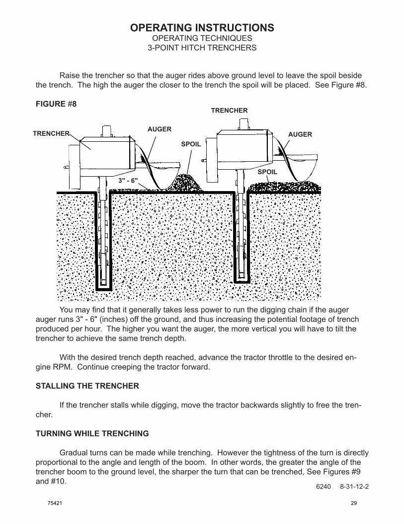
Raise the trencher so that the auger rides above ground level to leave the spoil beside the trench. The high the auger the closer to the trench the spoil will be placed. See Figure #8.
FIGURE #8
You may find that it generally takes less power to run the digging chain if the auger auger runs 3" - 6" (inches) off the ground, and thus increasing the potential footage of trench produced per hour. The higher you want the auger, the more vertical you will have to tilt the trencher to achieve the same trench depth.
With the desired trench depth reached, advance the tractor throttle to the desired en-gine RPM. Continue creeping the tractor forward.
STALLING THE TRENCHER
If the trencher stalls while digging, move the tractor backwards slightly to free the tren-cher.
TURNING WHILE TRENCHING
Gradual turns can be made while trenching. However the tightness of the turn is directly proportional to the angle and length of the boom. In other words, the greater the angle of the trencher boom to the ground level, the sharper the turn that can be trenched, See Figures #9 and #10.
AUGER
SPOIL
3" - 6"SPOIL
AUGER
TRENCHER
TRENCHER
6240 8-31-12-2
75421 29

OPERATING INSTRUCTIONS
6241 8-8-08-2
OPERATING TECHNIQUES3-POINT HITCH TRENCHERS
Also the shorter the boom length the sharper the possible turn. Remember, the greater the increase in boom angle the higher the unit will have to be raised out of the trench to keep a unified trench depth. Shallow boom angles will severely limit turning ability.
IMPORTANT: Turning to tightly while trenching will cause the trencher to jam in the trench and stall. Turning to tightly can also cause the trencher boom to bend. Take it easy when turning. Proceed slowly with caution.
FIGURE #9
FIGURE #10TURNING WITH THE BOOMAT A 60° DIGGING ANGLE
TURNING WITH THE BOOMAT MAXIMUM DIGGING ANGLE
TOP VIEW
TOP VIEW
MAKING SHARP TURNS
To make sharp turns and 90° angle you will have to dig two trenches. Dig the first trench as you normally would. Then reposition the unit and dig the second trench at the appro-priate angle. Be sure to take into account the extra lead-in space needed for the trencher to get down to the desired trench depth. See Figure #11.
30 75421

OPERATING INSTRUCTIONS
6242 5-28-08-2
OPERATING TECHNIQUES3-POINT HITCH TRENCHERS
FIGURE #11
TOP VIEW
1st TRENCH
2nd TRENCH
RECOMMENDED DIGGING ANGLES
A 90° digging angle is recommended for use in rock and frost conditions, and when trenching sharp corners. The 90° angle reduces excessive side pressure on the boom and digging chain when trenching corners.
A 60° - 65° digging angle is recommended for normal trenching. At this angle there will be less carryover, and a cleaner trench bottom than can be maintained at a 90° angle.
TRENCHING WITHOUT THE CRUMBER BAR / PERSONAL RESTRAINT BAR
WARNING! The crumber bar / personal restraint bar and crumber assembly are there for a reason, YOUR SAFETY! There are a few instances however, where removal may be necessary. In these cases operate with extreme caution. Reinstall the crumber bar / personal restraint bar and crumber assembly as soon as possible.
You can use your trencher to dig under obstacles such as sidewalks. To do so, remove the crumber bar / personal restraint bar and crumber assembly and start your trench as before within a foot of the sidewalk. With the crumber bar / personal restraint bar removed you can start the trench vertically without any lead-in space.
When the desired depth has been reached, tilt the trencher at 60° angle while digging, then creep the tractor backward and trench under the side walk. Be careful not to contact the edge of the sidewalk with the digging teeth.
75421 31

OPERATING INSTRUCTIONSOPERATING TECHNIQUES
3-POINT HITCH TRENCHERS
After you have gone as far as you can without contacting the sidewalk, drive the trac-tor forward to clear the sidewalk and remove the trencher from the trench. Line up the unit on the other side of the walk and continue to trench as described above until the two trenches are connected. See Figure #12.
FIGURE #12
CREEP BACKWARD
CRUMBER BAR AND ASSEMBLY REMOVED. REPLACE AS SOON AS
POSSIBLE.
SIDEWALK
1st TRENCH2nd TRENCH
AVOID CONTACTING SIDEWALK
6243 8-29-12-2
Reinstall the crumber bar / personal restraint bar and crumber assembly immediately. Some spoil will be left in the trench since the crumber was removed during the operation.
ENDING THE TRENCH
When you have dug your trench, remember that the trencher boom is at an angle, and that you must continue trenching until the end of the boom has dug past the proposed end of the trench. Once the end of the trench has been dug, keep the trencher running and lift the unit clear of the trench. When the trencher has cleared the trench, disengage the PTO to stop the trencher. Drive the tractor away from the trench.
32 75421

OPERATING INSTRUCTIONS
6244 5-28-08-2
OPERATING TECHNIQUES3-POINT HITCH TRENCHERS
TRANSPORTING THE TRENCHER
When transporting the trencher, remember to keep the trencher as low to the ground as is practical. The lower the trencher rides, the more stable the tractor will be. You do not want the trencher so low that the digging teeth touch ground in rough terrain. Shut off the trencher before moving it away from the trench. Never transport the trencher around the job site or any-where else while the digging chain is moving.
TRENCHER PERFORMANCE
Trencher performance is related to how well it's maintained, digging tooth wear, and type and size of digging chain, crumber boom and shoe used. If problems arise see "Trouble Shooting" Section.
75421 33

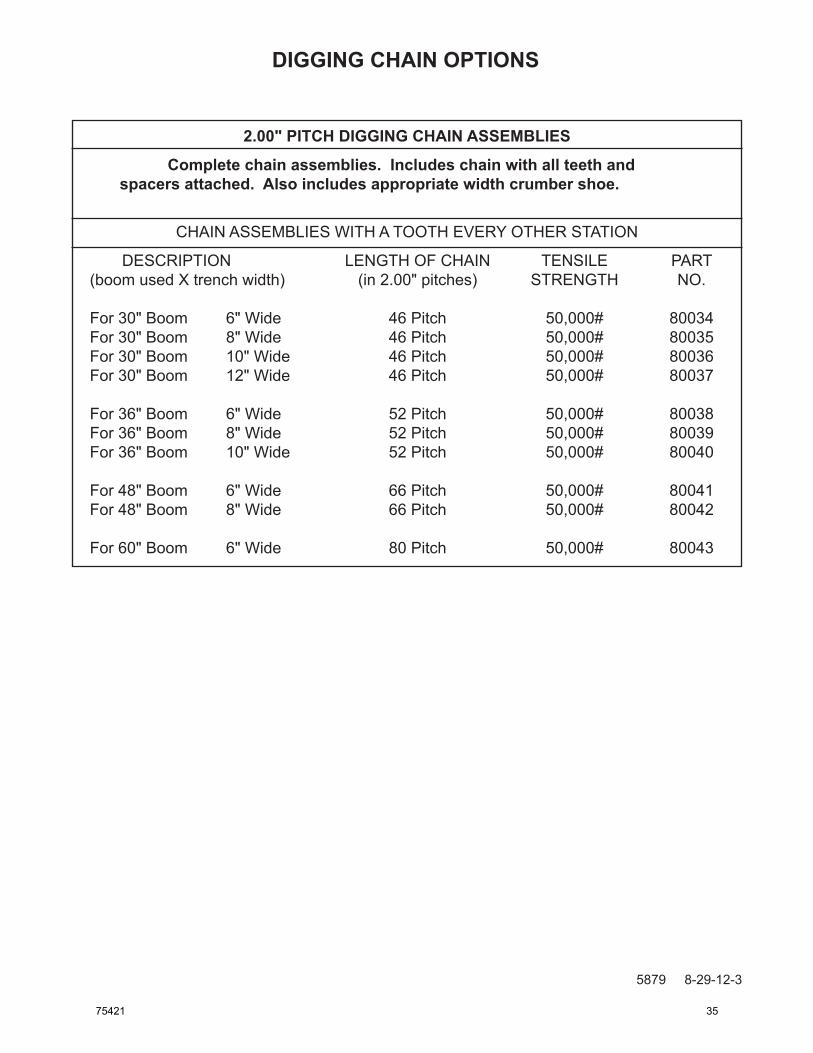
DIGGING CHAIN OPTIONS2.00" PITCH DIGGING CHAIN ASSEMBLIES
GENERAL INFORMATION
This page contains a listing of all of the 2.00" pitch digging chain assemblies offered for your trencher. Each chain assembly comes with all necessary teeth and spacers already installed. Just thread the chain onto the trencher and fasten the two ends together with the pin and keeper pin included in the assembly. A crumber shoe of the appropriate width is also included in the chain assembly.
Before you order a new chain, be sure to check for compatibility with corresponding components. You may need to order more than just a chain assembly. You must use a dig-ging boom of the same digging depth as the chain. The crumber bar must also be of the same digging depth. The digging sprocket must also be of the same pitch as the chain. All of these components must match for the trencher to function properly.
Bare 2.00" pitch digging chain (without teeth, spacers, or hardware) can be ordered in any desired length under the part number 79018. Just use this number and then specify the length desired in pitches (example, 52 pitches of chain would be needed for a 36" boom).
2.00" PITCH DIGGING CHAIN ASSEMBLIES
Complete chain assemblies. Includes chain with all teeth and spacers attached. Also includes appropriate width crumber shoe.
CHAIN ASSEMBLIES WITH A TOOTH EVERY STATION
DESCRIPTION LENGTH OF CHAIN TENSILE PART (boom used X trench width) (in 2.00" pitches) STRENGTH NO.
For 30" Boom 6" Wide 48 Pitch 50,000# 80044 For 30" Boom 8" Wide 46 Pitch 50,000# 80045 For 30" Boom 10" Wide 46 Pitch 50,000# 80046 For 30" Boom 12" Wide 46 Pitch 50,000# 80047
For 36" Boom 6" Wide 52 Pitch 50,000# 80048 For 36" Boom 8" Wide 52 Pitch 50,000# 80049 For 36" Boom 10" Wide 52 Pitch 50,000# 80050
For 48" Boom 6" Wide 66 Pitch 50,000# 80051 For 48" Boom 8" Wide 66 Pitch 50,000# 80052
For 60" Boom 6" Wide 80 Pitch 50,000# 80053
5878 8-29-12-3
34 75421
DIGGING CHAIN OPTIONS
2.00" PITCH DIGGING CHAIN ASSEMBLIES
Complete chain assemblies. Includes chain with all teeth and spacers attached. Also includes appropriate width crumber shoe.
CHAIN ASSEMBLIES WITH A TOOTH EVERY OTHER STATION
DESCRIPTION LENGTH OF CHAIN TENSILE PART (boom used X trench width) (in 2.00" pitches) STRENGTH NO.
For 30" Boom 6" Wide 46 Pitch 50,000# 80034 For 30" Boom 8" Wide 46 Pitch 50,000# 80035 For 30" Boom 10" Wide 46 Pitch 50,000# 80036 For 30" Boom 12" Wide 46 Pitch 50,000# 80037
For 36" Boom 6" Wide 52 Pitch 50,000# 80038 For 36" Boom 8" Wide 52 Pitch 50,000# 80039 For 36" Boom 10" Wide 52 Pitch 50,000# 80040
For 48" Boom 6" Wide 66 Pitch 50,000# 80041 For 48" Boom 8" Wide 66 Pitch 50,000# 80042
For 60" Boom 6" Wide 80 Pitch 50,000# 80043
5879 8-29-12-3
75421 35

DIGGING CHAIN OPTIONS2.00" PITCH CHAIN REPLACEMENT PARTS
5806 8-29-12-2
GENERAL INFORMATION You can purchase individual chain links and pins for your trencher. These can be used to repair a damaged chain, or lengthen and modify an existing chain. Below is a diagram of the chain’s basic components with their descriptions and corresponding part numbers. Use these numbers when ordering. You can also order a complete bare chain (without teeth and spacers) in any length desired. The chain is ordered under part number 79018 for 2.00" Pitch. Just specify the length you want in pitches. (See “2.00” PITCH DIGGING CHAIN ASSEM-BLIES” chart located in this section.)
Whenpinninglinksofchaintogether,firsttapthepinthroughtheconnectorlinkwiththe perfectly round holes and then on through the inner link. Place the second connector link inposition,youwillnotethattheendofthepinhasonesideflattened.Rotatethepinuntilitsflatsidelinesupwiththecorrespondingflatsideoftheconnectorlinkholeandtapthepinon through. Place the chain keeper pin into the hole at the end of the main pin and tap down tight. Finally, bend the end of the keeper pin over to secure it in place.
NO. REQ’D PART NO. DESCRIPTION
1 Varies 54757 Inner Link 2 Varies 54731 Pin 3 Varies 54732 Chain Keeper Pin 4 Varies 54730 Connector Link includes (2) Pins #54731 and (2) Chain Keeper Pins #54732
36 75421

DIGGING CHAIN OPTIONS2.00" PITCH DIGGING TOOTH STATION SEQUENCE
GENERAL INFORMATION Every second link on a digging chain is a special link called a digging station. These digging station links are designed so that digging teeth can be bolted onto them in a variety of configurations. It is the number and the make up of these different digging stations that make each chain unique.
The following tables show the number of digging stations there are in each available 2.00" pitch digging chain. The digging tooth make up of each digging station is given in code. The key to the code is located at the below. Thus these charts will tell you what kind of dig-ging tooth arrangement is at each digging station on each digging chain assembly. The actual parts break down on each digging tooth arrangement is shown on the "Digging Tooth Station Break Down" diagrams located in this section following the charts.
TOOTH EVERY STATION
30" BOOMDIGGING TOOTH STATIONS
48" BOOMDIGGING TOOTH STATIONS
TRENCHWIDTH
5880 8-29-12-3
36" BOOMDIGGING TOOTH STATIONS
TRENCHWIDTH
TRENCHWIDTH
DIGGING TOOTH STATION KEY
CR - CENTER CUTTER, RIGHT 6R - 6" RIGHT STATION 8R - 8" RIGHT STATION CL - CENTER CUTTER, LEFT 6L - 6" LEFT STATION 8L - 8" LEFT STATION
10 - 10" STATION 12 - 12" STATION B - BLANK STATION
75421 37

DIGGING CHAIN OPTIONS2.00" PITCH DIGGING TOOTH STATION SEQUENCE
TOOTH EVERY OTHER STATION
30" BOOMDIGGING TOOTH STATIONS
36" BOOMDIGGING TOOTH STATIONS
48" BOOMDIGGING TOOTH STATIONS
60" BOOMDIGGING TOOTH STATIONS
TOOTH EVERY STATION
60" BOOMDIGGING TOOTH STATIONS
TRENCHWIDTH
TRENCH WIDTH
TRENCH WIDTH
TRENCH WIDTH
TRENCH WIDTH
5881 8-29-12-338 75421

DIGGING CHAIN OPTIONS2.00" PITCH DIGGING TOOTH STATION BREAK DOWN
GENERAL INFORMATION
The following diagrams are the complete parts break downs of all the different digging tooth arrangements used on the digging stations for 2.00" pitch chains. The diagrams are fron-tal views according to the digging chain direction of travel. All 2.00" pitch chains are made up of a combination of some or all of these various digging tooth arrangements. See the "2.00" Pitch Digging Tooth Station Sequence Charts" (located earlier in this section) to find out how the arrangements are used for the various digging chains.
DIRT TOOTH, LEFTPART #54431
DIRT TOOTH, RIGHTPART #54432
1.56" SPACER TUBEPART #54628
3.25" CAPSCREWPART #1347
WITH NUT #1692
DIRT TOOTH, LEFTPART #54431
DIRT TOOTH, RIGHTPART #54432
1.81" SPACER TUBEPART #54440
3.25" CAPSCREWPART #1347
WITH NUT #1692
CENTER CUTTER, RIGHTCENTER CUTTER, LEFT
6" LEFT STATION 6" RIGHT STATION
5809 8-29-12-275421 39

DIGGING CHAIN OPTIONS2.00" PITCH DIGGING TOOTH STATION BREAK DOWN
DIRT TOOTH, LEFTPART #54431
DIRT TOOTH, RIGHTPART #54432
SPACER BARPART #54439
1.81" SPACER TUBEPART #54440
4.50" CAPSCREWPART #1351
WITH NUT #1692
DIRT TOOTH, LEFTPART #54431
DIRT TOOTH, RIGHTPART #54432
10" CHAIN SPACERPART #54441
3.25" CAPSCREWPART #1347
WITH NUT #1692
6.50
5810 8-29-12-2
8" RIGHT STATION8" LEFT STATION
10" STATION
40 75421

DIGGING CHAIN OPTIONS2.00" PITCH DIGGING TOOTH STATION BREAK DOWN
DIRT TOOTH, LEFTPART #54431
DIRT TOOTH, RIGHTPART #54432
12" CHAIN SPACERPART #54442
4.50" CAPSCREWPART #1351
WITH FLAT WASHER #1527AND NUT #1692
8.50
5811 8-29-12-2
12" STATION
75421 41

DIGGING CHAIN OPTIONS2.00" PITCH DIGGING CHAIN WIDTH CONVERSIONS
5812 8-29-12-2
GENERAL INFORMATION
Diggingchainscanbemodifiedtodigtrenchesinavarietyofwidths.Bymodifyinganexistingchain,itcanbeusedtodigthewidthyouwantandthussavegoingtheexpenseofawholenewdiggingchainassembly.Thiscanbeaconsiderablecostsavings,howeveritismoreworkthanjustinstallinganewdiggingchainassembly.
Theinformationgivenbelowisacompletelistingofallthepossiblechainwidthconver-sionsfor2.00"pitchchainforyourtrencher.Includedinthelistingisabreakdownofalltheparts(includingpartnumbersandquantities)neededtomaketheconversion.Simplyinstallthenewparts(andrearrangetheoldparts)sothatthefinishedchainconstructionfollowsthatdescribedinthe“DiggingToothStationSequence”chartandthe“DiggingToothStationBreakDown”diagramsfor2.00"pitchchain(locatedelsewhereinthissection).
Itshouldbenotedthatthisinformationonlyappliestomodifyingchainsofthesamelengthandpitch.Allcomponentsmustbeofthesamepitch.Youcannotintermixcomponentsofdifferentpitch.
CHAIN CONVERSIONS FOR 30" BOOMS - TOOTH EVERY STATION
1) FROM 6" WIDE TO 8" WIDE
REQ’D PART NO. DESCRIPTION
20 1351 .50"UNFX4.50"Capscrew 2 54440 SpacerTube 10 54439 8"Spacer 1 53055 8"CrumberShoe
2) FROM 8" WIDE TO 6" WIDE
REQ’D PART NO. DESCRIPTION
20 1347 .50"UNFX3.25"Capscrew 2 54628 SpacerTube 1 53054 6"CrumberShoe
42 75421

DIGGING CHAIN OPTIONS2.00" PITCH DIGGING CHAIN WIDTH CONVERSIONS
3) FROM 6" WIDE TO 10" WIDE
REQ'D PART NO. DESCRIPTION
8 1692 .50" UNF High Hex Nut 16 1351 .50"UNF X 4.50" Capscrew 2 54431 Left Tooth 2 54432 Right Tooth 4 54441 10" Chain Spacer 1 53058 10" Crumber Shoe 8 54439 8" Spacer
4) FROM 10" WIDE TO 6" WIDE
REQ'D PART NO. DESCRIPTION
8 1347 .50"UNF X 3.25" Capscrew 4 54628 Spacer Tube 4 54440 Spacer Tube 1 53054 6" Crumber Shoe
5) FROM 6" WIDE TO 12" WIDE
REQ'D PART NO. DESCRIPTION
12 1692 .50" UNF High Hex Nut 26 1351 .50"UNF X 4.50" Capscrew 12 1527 .50" SAE Flat Washer 3 54431 Left Tooth 3 54432 Right Tooth 3 54441 10" Chain Spacer 3 54442 12" Chain Spacer 1 53059 12" Crumber Shoe 7 54439 8" Spacer
6) FROM 12" WIDE TO 6" WIDE
REQ'D PART NO. DESCRIPTION
14 1347 .50"UNF X 3.25" Capscrew 4 54628 Spacer Tube 8 54440 Spacer Tube 1 53054 6" Crumber Shoe
5882 8-29-12-2
75421 43

DIGGING CHAIN OPTIONS2.00" PITCH DIGGING CHAIN WIDTH CONVERSIONS
7) FROM 8" WIDE TO 10" WIDE
REQ'D PART NO. DESCRIPTION
8 1692 .50" UNF High Hex Nut 12 1347 .50"UNF X 3.25" Capscrew 2 54431 Left Tooth 2 54432 Right Tooth 4 54441 10" Chain Spacer 1 53058 10" Crumber Shoe
8) FROM 10" WIDE TO 8" WIDE
REQ'D PART NO. DESCRIPTION
4 1351 .50"UNF X 4.50" Capscrew 2 54628 Spacer Tube 6 54440 Spacer Tube 2 54439 8" Spacer 1 53055 8" Crumber Shoe
9) FROM 8" WIDE TO 12" WIDE
REQ'D PART NO. DESCRIPTION
12 1692 .50" UNF High Hex Nut 6 1347 .50"UNF X 3.25" Capscrew 6 1351 .50"UNF X 4.50" Capscrew 12 1527 .50" SAE Flat Washer 3 54431 Left Tooth 3 54432 Right Tooth 3 54441 10" Chain Spacer 3 54442 12" Chain Spacer 1 53059 12" Crumber Shoe
10) FROM 12" WIDE TO 8" WIDE
REQ'D PART NO. DESCRIPTION
2 54628 Spacer Tube 10 54440 Spacer Tube 3 54439 8" Spacer 1 53055 8" Crumber Shoe
5883 8-29-12-2
44 75421

DIGGING CHAIN OPTIONS2.00" PITCH DIGGING CHAIN WIDTH CONVERSIONS
11) FROM 10" WIDE TO 12" WIDE
REQ'D PART NO. DESCRIPTION
4 1692 .50" UNF High Hex Nut 10 1351 .50"UNF X 4.50" Capscrew 12 1527 .50" SAE Flat Washer 1 54431 Left Tooth 1 54432 Right Tooth 3 54442 12" Chain Spacer 1 53059 12" Crumber Shoe
12) FROM 12" WIDE TO 10" WIDE
REQ'D PART NO. DESCRIPTION
6 1347 .50"UNF X 3.25" Capscrew 4 54440 Spacer Tube 1 54441 10" Chain Spacer 1 53058 10" Crumber Shoe
CHAIN CONVERSIONS FOR 36" BOOMS - TOOTH EVERY STATION
1) FROM 6" WIDE TO 8" WIDE
REQ'D PART NO. DESCRIPTION
20 1351 .50"UNF X 4.50" Capscrew 2 54440 Spacer Tube 10 54439 8" Spacer 1 53055 8" Crumber Shoe
2) FROM 8" WIDE TO 6" WIDE
REQ'D PART NO. DESCRIPTION
20 1347 .50"UNF X 3.25" Capscrew 2 54628 Spacer Tube 1 53054 6" Crumber Shoe
5884 8-29-12-275421 45

DIGGING CHAIN OPTIONS2.00" PITCH DIGGING CHAIN WIDTH CONVERSIONS
3) FROM 6" WIDE TO 10" WIDE
REQ'D PART NO. DESCRIPTION
8 1692 .50" UNF High Hex Nut 18 1351 .50"UNF X 4.50" Capscrew 2 54431 Left Tooth 2 54432 Right Tooth 4 54441 10" Chain Spacer 1 53058 10" Crumber Shoe 9 54439 8" Spacer
4) FROM 10" WIDE TO 6" WIDE
REQ'D PART NO. DESCRIPTION
10 1347 .50"UNF X 3.25" Capscrew 2 54628 Spacer Tube 6 54440 Spacer Tube 1 53054 6" Crumber Shoe
5) FROM 8" WIDE TO 10" WIDE
REQ'D PART NO. DESCRIPTION
8 1692 .50" UNF High Hex Nut 10 1347 .50"UNF X 3.25" Capscrew 2 54431 Left Tooth 2 54432 Right Tooth 4 54441 10" Chain Spacer 1 53058 10" Crumber Shoe
6) FROM 10" WIDE TO 8" WIDE
REQ'D PART NO. DESCRIPTION
2 1351 .50"UNF X 4.50" Capscrew 8 54440 Spacer Tube 1 54439 8" Spacer 1 53055 8" Crumber Shoe
5885 8-29-12-246 75421
DIGGING CHAIN OPTIONS2.00" PITCH DIGGING CHAIN WIDTH CONVERSIONS
5817 8-29-12-2
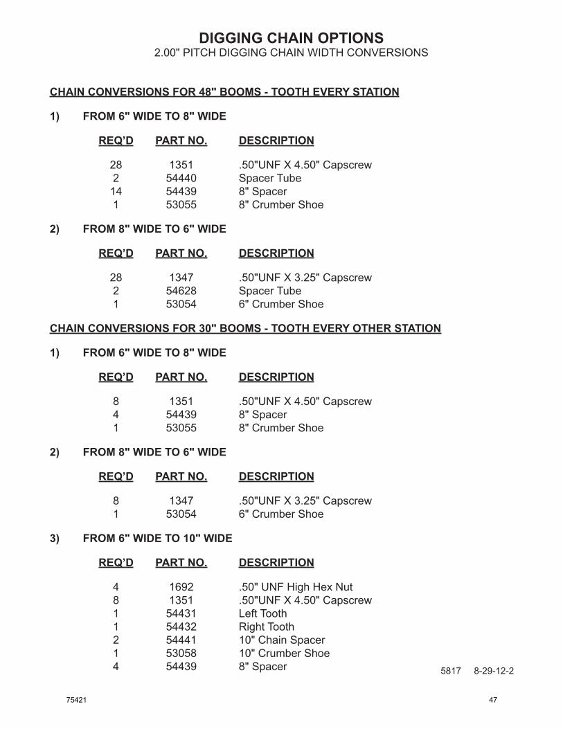
CHAIN CONVERSIONS FOR 48" BOOMS - TOOTH EVERY STATION
1) FROM 6" WIDE TO 8" WIDE
REQ’D PART NO. DESCRIPTION
28 1351 .50"UNF X 4.50" Capscrew 2 54440 Spacer Tube 14 54439 8" Spacer 1 53055 8" Crumber Shoe
2) FROM 8" WIDE TO 6" WIDE
REQ’D PART NO. DESCRIPTION
28 1347 .50"UNF X 3.25" Capscrew 2 54628 Spacer Tube 1 53054 6" Crumber Shoe
CHAIN CONVERSIONS FOR 30" BOOMS - TOOTH EVERY OTHER STATION
1) FROM 6" WIDE TO 8" WIDE
REQ’D PART NO. DESCRIPTION
8 1351 .50"UNF X 4.50" Capscrew 4 54439 8" Spacer 1 53055 8" Crumber Shoe
2) FROM 8" WIDE TO 6" WIDE
REQ’D PART NO. DESCRIPTION
8 1347 .50"UNF X 3.25" Capscrew 1 53054 6" Crumber Shoe
3) FROM 6" WIDE TO 10" WIDE
REQ’D PART NO. DESCRIPTION
4 1692 .50" UNF High Hex Nut 8 1351 .50"UNF X 4.50" Capscrew 1 54431 Left Tooth 1 54432 Right Tooth 2 54441 10" Chain Spacer 1 53058 10" Crumber Shoe 4 54439 8" Spacer
75421 47

DIGGING CHAIN OPTIONS2.00" PITCH DIGGING CHAIN WIDTH CONVERSIONS
5818 8-29-12-2
4) FROM 10" WIDE TO 6" WIDE
REQ’D PART NO. DESCRIPTION
4 1347 .50"UNF X 3.25" Capscrew 2 54628 Spacer Tube 2 54440 Spacer Tube 1 53054 6" Crumber Shoe
5) FROM 6" WIDE TO 12" WIDE
REQ’D PART NO. DESCRIPTION
8 1692 .50" UNF High Hex Nut 16 1351 .50"UNF X 4.50" Capscrew 8 1527 .50" SAE Flat Washer 2 54431 Left Tooth 2 54432 Right Tooth 2 54441 10" Chain Spacer 2 54442 12" Chain Spacer 1 53059 12" Crumber Shoe 4 54439 8" Spacer
6) FROM 12" WIDE TO 6" WIDE
REQ’D PART NO. DESCRIPTION
8 1347 .50"UNF X 3.25" Capscrew 2 54628 Spacer Tube 6 54440 Spacer Tube 1 53054 6" Crumber Shoe
7) FROM 8" WIDE TO 10" WIDE
REQ’D PART NO. DESCRIPTION
4 1692 .50" UNF High Hex Nut 4 1347 .50"UNF X 3.25" Capscrew 1 54431 Left Tooth 1 54432 Right Tooth 2 54441 10" Chain Spacer 1 53058 10" Crumber Shoe
48 75421

DIGGING CHAIN OPTIONS2.00" PITCH DIGGING CHAIN WIDTH CONVERSIONS
5819 8-29-12-2
8) FROM 10" WIDE TO 8" WIDE
REQ’D PART NO. DESCRIPTION
2 54628 Spacer Tube 2 54440 Spacer Tube 1 53055 8" Crumber Shoe
9) FROM 8" WIDE TO 12" WIDE
REQ’D PART NO. DESCRIPTION
8 1692 .50" UNF High Hex Nut 8 1351 .50"UNF X 4.50" Capscrew 8 1527 .50" SAE Flat Washer 2 54431 Left Tooth 2 54432 Right Tooth 2 54441 10" Chain Spacer 2 54442 12" Chain Spacer 1 53059 12" Crumber Shoe
10) FROM 12" WIDE TO 8" WIDE
REQ’D PART NO. DESCRIPTION
2 54628 Spacer Tube 6 54440 Spacer Tube 1 53055 8" Crumber Shoe
11) FROM 10" WIDE TO 12" WIDE
REQ’D PART NO. DESCRIPTION
4 1692 .50" UNF High Hex Nut 8 1351 .50"UNF X 4.50" Capscrew 8 1527 .50" SAE Flat Washer 1 54431 Left Tooth 1 54432 Right Tooth 2 54442 12" Chain Spacer 1 53059 12" Crumber Shoe
75421 49

DIGGING CHAIN OPTIONS2.00" PITCH DIGGING CHAIN WIDTH CONVERSIONS
12) FROM 12" WIDE TO 10" WIDE
REQ'D PART NO. DESCRIPTION
4 1347 .50"UNF X 3.25" Capscrew 4 54440 Spacer Tube 1 53058 10" Crumber Shoe
CHAIN CONVERSIONS FOR 36" BOOMS - TOOTH EVERY OTHER STATION
1) FROM 6" WIDE TO 8" WIDE
REQ'D PART NO. DESCRIPTION
10 1351 .50"UNF X 4.50" Capscrew 5 54439 8" Spacer 1 53055 8" Crumber Shoe
2) FROM 8" WIDE TO 6" WIDE
REQ'D PART NO. DESCRIPTION
10 1347 .50"UNF X 3.25" Capscrew 1 53054 6" Crumber Shoe
3) FROM 6" WIDE TO 10" WIDE
REQ'D PART NO. DESCRIPTION
4 1692 .50" UNF High Hex Nut 8 1351 .50"UNF X 4.50" Capscrew 1 54431 Left Tooth 2 54441 10" Chain Spacer 1 53058 10" Crumber Shoe 4 54439 8" Spacer
4) FROM 10" WIDE TO 6" WIDE
REQ'D PART NO. DESCRIPTION
4 1347 .50"UNF X 3.25" Capscrew 4 54440 Spacer Tube 1 53054 6" Crumber Shoe
5886 8-29-12-2
50 75421

DIGGING CHAIN OPTIONS2.00" PITCH DIGGING CHAIN WIDTH CONVERSIONS
5) FROM 8" WIDE TO 10" WIDE
REQ'D PART NO. DESCRIPTION
4 1692 .50" UNF High Hex Nut 6 1347 .50"UNF X 3.25" Capscrew 2 54431 Left Tooth 2 54441 10" Chain Spacer 1 53058 10" Crumber Shoe
6) FROM 10" WIDE TO 8" WIDE
REQ'D PART NO. DESCRIPTION
2 1351 .50"UNF X 4.50" Capscrew 4 54440 Spacer Tube 1 54439 8" Spacer 1 53055 8" Crumber Shoe
CHAIN CONVERSIONS FOR 48" BOOMS - TOOTH EVERY OTHER STATION
1) FROM 6" WIDE TO 8" WIDE
REQ'D PART NO. DESCRIPTION
14 1351 .50"UNF X 4.50" Capscrew 2 54440 Spacer Tube 7 54439 8" Spacer 1 53055 8" Crumber Shoe
2) FROM 8" WIDE TO 6" WIDE
REQ'D PART NO. DESCRIPTION
14 1347 .50"UNF X 3.25" Capscrew 2 54628 Spacer Tube 1 53054 6" Crumber Shoe
5887 8-29-12-2
75421 51

6824 8-29-12-2
STATION #1 STATION #3STATION #2
STATION #4 STATION #5 STATION #6
STATION #7 STATION #8 STATION #9
STATION #10 STATION #11 STATION #12
12 123
13
4
15
1013 14
10 16 16 10
14
3 4
13
10 15 15 10
13
1710
34
14
10 18 1710
14
3414
10 19
9 9
10 1510 15 15 10
111
211
2 111 11
6 5
8 7
11
14
11
DIGGING CHAIN OPTIONSCOMBINATION ROCK AND FROST CHAIN
2.00" PITCH - TOOTH EVERY STATIONSERVICE PARTS
52 75421

ITEM PART NO. DESCRIPTION
1 21125 Carbide Bit Holder - 4” Right 2 21124 Carbide Bit Holder - 4” Left
3 54432 Cup Cutter - Right 4 54431 Cup Cutter - Left
5 21126 Carbide Bit Holder - 5” Right (1) Weld Spot on Top for Identifying Purposes 6 21127 Carbide Bit Holder - 5” Left (1) Weld Spot on Top for Identifying Purposes
7 21129 Carbide Bit Holder - 6” Right (2) Weld Spots on Top for Identifying Purposes 8 21128 Carbide Bit Holder - 6” Left (2) Weld Spots on Top for Identifying Purposes
9 83800 Spacer - 6” Cut 10 1692 .50” UNF Hex Nut
11 7061 Carbide Bit 12 83798 Tube Spacer (Inside Mount Carbide Bit Holder)
13 54628 Tube Spacer (Inside Mount Cup Cutter) 14 54440 Tube Spacer (Outside Cup or Carbide Bit Holder)
15 1347 .50” UNF X 3.25” Hex Capscrew 16 1349 .50” UNF X 3.75” Hex Capscrew
17 1351 .50” UNF X 4.50” Hex Capscrew 18 1348 .50” UNF X 3.50” Hex Capscrew
19 1350 .50” UNF X 4.00” Hex Capscrew
6825 8-29-12-2
NOTE: There are weld spots located on the top of the 5" and 6" Carbide Bit Holders to assist in parts identification. One weld spot on the 5" Holders and two weld spots on the 6" Holders.
DIGGING CHAIN OPTIONSCOMBINATION ROCK AND FROST CHAIN
2.00" PITCH - TOOTH EVERY STATIONSERVICE PARTS
75421 53

LUBRICATION
6178 8-29-12-2
GENERAL INFORMATION Economicalandefficientoperationofanymachineisdependentuponregularandprop-erlubricationofallmovingpartswithaqualitylubricant.Neglectleadstoreducedefficiency,heavydraft,wear,breakdown,andneedlessreplacementparts. Allpartsprovidedwithgreasefittingsshouldbelubricatedasindicated.Ifanygreasefittingsaremissing,replacethemimmediately.Cleanallfittingsthoroughlybeforeusinggreasegun.
IMPORTANT: Avoid excessive greasing. Dirt collects on exposed grease and greatly increases wear. After greasing, wipe off excessive grease from fittings.
EVERY 40 HOURS OF OPERATION Theoillevelinthegearboxshouldbecheckedonceaweek.Properleveloflubricantinthegearboxisapprox.3.50"(about6pints).Fillasnecessarywith#90transmissionoil. Thepreviouslymentionedareasaretheonlyonesthatrequirelubrication.Nolubrica-tionisneededonanyotherpartofthetrencher.Boomassembliesdonotrequireanylubricat-ing.DO NOTlubricatethediggingchain.Lubricatingthechainwillonlycausedirttocollectonthechainresultinginincreasedchainwear.
* When used in winter the outer tube must be greased to prevent it freezing solid!
8H 8H8H 8H
FrequencyofLubrication:(Swingjointsidewaysforgreasing.)
LUBRICATION Lubricategreasezerksatmainframe/gearboxpivotandalsoatendofliftcylinder,every(8)eighthours. GreasePTODrivebeforeputtingtrencherintooperationandatspecifiedintervalsthereafter.
GREASE INSIDE OF OUTER TELESCOPING TUBE (EVERY 20 HOURS)
54 75421

MAINTENANCE
6218 8-29-12-2
GENERAL INFORMATION
Regular maintenance is the key to long equipment life and safe operation. Maintenance requirements have been reduced to an absolute minimum. However, it is very important that these maintenance functions be performed as described below.
CAUTION! Always choose level and hard ground to park the tractor on and set the brake so that the tractor cannot roll. Never perform maintenance on the trencher when the tractor engine is running.
The main part of the maintenance procedure is proper lubrication. This information is covered in detail in Section "H". Be sure to follow the recommended lubrication time intervals. This is crucial to your trencher's longevity.
Trenchers are subject to extreme vibration due to their very nature. Be sure to check the trencher and its mounting daily for loose bolts and hardware. Tighten according to the bolt torque specification charts found in Section "O".
THE HYDRAULIC SYSTEM
WARNING! Escapingfluidunderpressurecanhavesufficientforcetopenetratetheskin causing serious personal injury. Fluid escaping from a very small hole can be almost invisible. Use a piece of cardboard or wood, rather than hands to search for suspected leaks.
Keep unprotected body parts, such as face, eyes, and arms as far away as possiblefromasuspectedleak.Fleshinjectedwithhydraulicfluidmaydevelop gangrene or other permanent disabilities.
Ifinjuredbyinjectedfluid,seeadoctoratonce.Ifyourdoctorisnotfamil-iar with this type of injury, ask him to research immediately to determine proper treatment.
The most common cause of premature wear and malfunctioning of hydraulic system components is the ingress of contaminants, incorrect pressure and pump cavitation.
75421 55

MAINTENANCE
Observe a high standard of cleanliness when doing valve or cylinder maintenance. Dur-ing maintenance cover or plug ends of disconnected hydraulic lines to prevent contaminants from entering. Use clean oil and a clean container when adding oil for hydraulic purposes. Use the tractor manufacturer's recommended hydraulic oil.
Refer to your hydraulic hose circuit if in doubt about the correct connection.
DIGGING CHAIN REMOVAL
1. To remove digging chain, position trencher boom in transport position and install jack stands under trencher mainframe to achieve ground clearance and to support trencher.
2. Remove crumber assembly by loosening two jam nuts and set screws. Pull the crumber bar / personal restraint bar out of its support tube. See Figure #1
FIGURE #1
MAINFRAME CRUMBER BOOM TUBE
SET SCREW
LOOSEN JAM NUTS AND SET SCREWS TO REMOVE CRUM-
BER BOOM
CRUMBER BAR
JAM NUT
TRENCHER MAINFRAMEBOOM CLAMP PLATES
CLAMP PLATE BOLTS
BOOM TUBE
LOOSEN THE FOUR CLAMP PLATE BOLTS(THIS ALLOWS THE BOOM TUBE TO SLIDE LOOSENING THE DIGGING CHAIN.)
3. Relieve the chain tension. See Figures #2 and #3
FIGURE #2
6219 8-29-12-256 75421

MAINTENANCE
BOOM TUBEADJUSTING STUD
ADJUSTING NUT
FIGURE #3
LOOSEN THE FOUR CLAMP PLATE BOLTS AND TURN ADJUSTING NUT COUNTER CLOCKWISE UNTIL TENSION IS RELEASED
CAUTION! Once the digging chain has been removed the boom and boom end idler are free to come off. Be careful that these components do not fall off and possibly injure you or a bystander.
4. Remove one of the chain pins by straightening the chain keeper pin and removing it with a pliers. The pin can now be pulled or driven out. See Figure #4
FIGURE #4
BOOM CLAMP PLATESCLAMP
TRENCHER MAINFRAME
PLATE BOLTS
6220 8-29-12-2
5. Carefully remove the digging chain from the boom end idler and drive sprocket.
REVERSE THE PROCEDURE TO REINSTALL THE DIGGING CHAIN.
PIN
KEEPER PIN
75421 57

MAINTENANCE
HEADSHAFT DRIVE SPROCKET REMOVAL
1. Toremovetheheadshaftdrivesprocket,firstremovethediggingchainandboom.
2. Removethespiralaugerbyremovingthethreeclampboltsandslidetheaugerofftheheadshaft.(Useawedgeorscrewdrivertospreadtheclampforeasyinstallationorremoval.)
3. Removetheheadshaftdrivesprocketbyremovingthetwoclampboltsandslidingthesprocketofftheheadshaft.(Useawedgeorscrewdrivertospreadtheclampforeasyinstallationorremoval.)
REVERSE THE PROCEDURE TO REINSTALL THE HEADSHAFT DRIVE SPROCKET.
BOOM END IDLER BEARING REMOVAL
1. Toremovetheboomendidlerbearingfirstremovethediggingchainaspreviouslyde-scribedinthissection.
2. Removethenylockcapscrewandthesquaresectionpinfromtheboomend.Theidlerspacersandwheelwillseparatefromthechainguideswhenthepinisremoved.SeeFigure#5.
FIGURE#5
3. Pressouttheidlerbearingfromtheidlerwheel.
4. Pressouttheidlerhub.
5. Checkidlerspacer,idlerwheel,andbearingforwearandreplaceasnecessary.
REVERSE THE PROCEDURE TO REINSTALL THE END IDLER.
SCREW
NYLOCK CAP-
IDLER SPACERSQUARE SECTION PIN
BOOM END
IDLER SPACER
IDLER WHEEL
BEARING
HUB
6221 8-29-12-2
58 75421

MAINTENANCE
6222 8-29-12-2
FRICTION CLUTCH - PTO DRIVE ASSEMBLY The 612 trencher friction clutches are belleville spring loaded, factory set units which do not require readjustment over the life of the friction discs. After each long period of inactivity the clutch must be slipped in order to avoid high torque settings caused by the friction plates sticking. The clutch can be purposely slipped by tightening the four nuts against the plate springs and then turning the clutch rapidly. Back off the nut upon completion and the design torque is automatically restored.
CAUTION! Any overheating caused by too long or too frequent operation of the clutch must be avoided, since this can damage the friction discs and clutch parts.
The condition of the friction discs can be determined without disassembling the clutch. See Figure #6FIGURE #6
Afterthefirst8hoursofoperationandthenat100hourintervalsthetrencherdrivechain should be checked for proper tension adjustment. Chain is properly adjusted when the long side of chain can be moved by hand ½" either way from centerline of chain. Improper adjustment will cause excessive wear on drive chain and drive sprockets.
New 20% Reduced 50% Reduced 70% Reduced Beyond Performance Performance Performance Use
Condition when new. If the thrust plate edges are no longer visible, new friction discs are needed.
DIGGING TOOTH REPLACEMENT Sharp teeth are important to good performance. When teeth wear out, production will drop sharply, increasing wear and tear on other components. Trenching chain costs per foot of trencher will increase dramatically.
Cup teeth wear on the tip and side bulge in varying amounts. Wear patterns change with different digging conditions. The following patterns and captions are approximate and shouldbeusedasaguidetohelpyoudetermineyourownbestcost/benefittoothreplace-menttime.Normalreplacementshouldbemadebetween30%and60%reductioninperfor-mance. Replacement is a simple bolt-on procedure.
75421 59

MAINTENANCEFRICTION CLUTCH
2625 8-29-12-3
ASSEMBLY
DISASSEMBLY
See disassembly instructions for quickdisconnect lock, ball type, on Form #4-QD.
If the clutch has a warning device, remove the sleeve with the leaf springs by prying it up with two screw drivers as illustrated.
Tighten the four hex nuts (12) uniformly until the clutch pack and hub are loose.
Use special tool SW18 to bend all four re-taining lugs back on the edge of the clutch housing.
Remove the thrust plate with Belleville spring(s) and lug ring (if used) to get at the friction disks, drive plates and hub for in-spection and service. (Note: K92 two plate does not use drive plates #8 & #9)
BRADCO units not equipped with warn-ing device.
Place hub and friction disks into the clutch housing. Note that items #8 & #9 are only used in the four plate clutch. Next, compress the Belleville spring(s) and the lug ring (if used) to the pressure plate by tightening the four hex nuts and placing them into the clutch hous-ing as illustrated.
With the lugs in place loosen the four hex nuts completely to the end of the threaded studs. (Replace the sleeve with the leaf springs for the warning device if used.)
Replace the quick-disconnect or clamp bolt assembly, if so equipped.
Use special tool SW18 to bend the retain-ing lugs inward over the Belleville spring edges to secure the spring(s) when you back the four hex nuts off. (Note: Wide lugs for one (1) Belleville spring, narrow lugs for two (2) Belleville springs.)
60 75421

MAINTENANCESAFETY SHIELD
2626 8-29-12-3
Use special tool SW21 to release bearing locking tabs and remove the shield from P.T.O. drive shaft half.
Or, clamp the P.T.O. yoke in the vise as shown to create pressure on the locking tabs and use a flat bladed screw driver to release one tab at a time to remove shield.
DISASSEMBLY
ASSEMBLY
Grease the shield bearing groove on the yoke and the telescoping tube before assembly. Place bearing ring in groove with the lock-ing tabs nearest the telescoping tube side.
To remove the old shield cone, cut the cone near the bearing cap being careful not to damage the cap. Heat the new shield cone by placing the contact portion in water heated to approximately 180° F. until it is very flexible. Then, pull it over the tube and on to the bearing cap. As it cools, the cone will return to its natural size and become secure for normal function.
To mount the shield on to the half shaft, place it over the telescoping member, align the locking tabs on the bearing in the appropriate channels of the bearing cap and push the shield into place or apply light blows until all three locking tabs are visible in the open-ings.
Attach safety chain.
1. Shield Cone2. Bearing Ring3. Outer shield tube with bearing cap4. Safety Chain5. Inner shield tube with bearing cap
1 2 3
4
52 1
4
75421 61

MAINTENANCEU-JOINT
2627 8-29-12-3
DISASSEMBLY
ASSEMBLY
Remove retaining rings (3).
Use special tool SW23 or SW27 to clamp the bearing bushing in the vise. Using either light hammer blows or by twisting the yoke, remove the bearing bushing.
Place joint in the vise as illustrated (do not clamp tight) and with light hammer blows, drive up the bearing bushing.
1. Quick-disconnect yoke coupling2. Cross and bearing kit coupling3. Retaining ring4. Inboard yoke
Clamp the yoke in the vise as illustrated. Remove the bearing bushing from the cross kit and place the cross into one of the yokes. Begin mounting the bearings by extending the cross journal out through the bearing bore. Place a bearing on it and holding the cross with one hand to position the bearing, tap with light hammer blows until you notice resistance. Do the same for the opposite bearing.
Using a flat surfaced drift punch or special tool SW28 drive the bearing in until the annular groove is visible.
Replace the retaining ring, make sure it is properly seated.
Grease the joint. Note that all four bearings are properly purged and rotate to make sure the U-joint will move freely.
Relieve the stress from the bearings and yoke by applying several sharp hammer blows to the yoke ears.
When installing the second yoke and bear-ings, make sure the grease zerk is positioned on the proper side for easy access when lubricating. Replace the bearings as described previously using the cross journal to help guide the bearings into the bore.
1 23 4
62 75421

MAINTENANCE AND SERVICE
10530 3-8-06
CYLINDER SEAL REPLACEMENT The following information is provided to assist you in the event you should need to repair or rebuild a hy-draulic cylinder. When working on hydraulic cylinders, make sure that the work area and tools are clean and free of dirt to prevent contamination of the hydraulic system and damage to the hydraulic cylinders. Always protect the active part of the cylinder rod (the chrome section). Nicks or scratches on the surface of the rod could result in cylinder failure. Clean all parts thoroughly with a cleaning solvent before reassembly.
DISASSEMBLY PROCEDUREIMPORTANT: Do not contact the active surface of the cylinder rod with the vise. Damage to the rod could result.
RETAINING RING TYPE GLAND1. Mount the cylinder tube securely in a vise. NOTICE: Do not clamp too tight and distort the tube. 2. Rotate the gland with a spanner wrench (available from your dealer), until the gland retaining ring appears in the milled slot.
Pry up the end of the gland retaining ring with a pointed tool. Rotate the gland with a spanner wrench while re-moving the retaining ring. NOTE: The gland and piston seal(s) can be pulled out and cut as they appear in the milled slot during disassembly. After cutting, pull them on out through the milled slot. 3. Pull the cylinder rod from the cylinder tube.
4. Inspect the piston and the bore of the cylinder tube for deep scratches or galling. If damaged, the piston and cylinder tube must be replaced. 5. Removethehexnut,piston,flatwasherorspacertube(ifsoequipped),andglandfromthecylinderrod.Ifthe cylinder rod is rusty, scratched, or bent, it must be replaced. 6. Remove and discard all old seals.
ASSEMBLY PROCEDUREIMPORTANT: Replace all seals even if they do not appear to be damaged. Failure to replace all seals may result in premature cylinder failure.1. Installthecylinderrodsealintheglandfirst.Becarefullnottodamagethesealintheprocessasitissome-whatdifficulttoinstall.Aspecialinstallationtoolisavailabletohelpwithinstallingtheseal.Simplyfittheendofthetool over the seal so that the large prong of the tool is on the outside of the seal, and the two smaller prongs on the inside. The lip of the seal should be facing towards the tool. Rotate the handles on the tool around to wrap the seal around the end of the tool.
75421 63

MAINTENANCE AND SERVICE
10531 3-8-06
O - RING
BACKUP WASHER
Now insert the seal into the gland from the inner end. Position the seal in its groove, and release and remove the tool. Press the seal into its seat the rest of the way by hand.NOTE: Threaded gland is shown in diagram for reference only.2. Install the new piston ring, rod wiper, O-rings, and backup washers, if applicable,onthepiston.Becarefulnottodamagetheseals.Cautionmustbeused when installing the piston ring. The ring must be stretched carefully over the piston with a smooth, round, pointed tool.3. Slidetheglandontothecylinderrodbeingcarefulnottodamagetherodwiper.Theninstallthespacer,orflatwasher(ifsoequipped),smallO-ring,piston,and hex nut onto the end of the cylinder rod.4. Securethecylinderrod(mountingend)inavise,withasupportatitscen-ter.Torquethenuttothevalueshownonthechartforthethreaddiameterofthecylinder rod.
Thread Diameter POUNDS - FEET 7/8" 150-200 *1" 230-325 1-1/8" 350-480 1-1/4" 490-670 1-3/8" 670-900
* 1" Thread Diameter WITH 1.25" Rod Diameter Min. 230 ft. lbs. Max. 250 ft. lbs.
IMPORTANT: Do not contact the active surface of the cylinder rod with the vise. Damage to the rod could result.
IMPORTANT: Ensure that the piston ring fits squarely into the cylinder tube and piston groove, otherwise the ring may be damaged and a leak will occur.
5. Applyalubricant(suchasLubriplate#105)tothepistonandteflonring.Insertthecylinderrodassemblyinto the cylinder tube.6. Rotate the gland with a spanner wrench until the hole (drilled into the retaining slot of the gland) appears in the milled slot of the cylinder tube. Insert the hooked end of the gland retaining rod into the hole.
Rotate the gland until the gland retaining rod forms a ring between the gland and the cylinder tube. When com-plete, the bent end of the gland retainer ring should be hidden (not turned so it is exposed in the slot) to prevent it from popping out.
WARNING! Cylinders serviced in the field are to be tested for leakage prior to the attachment being placed in work. Failure to test rebuilt cylinders could result in damage to the cylinder and/or the attachment, causing severe personal injury or even death.
64 75421

REMOVAL AND STORAGE
6177 8-29-12-2
TRENCHER REMOVAL When disconnecting the trencher from the tractor it is recommended that you follow the storage procedures below to keep your trencher in top condition and also help you get off to a good start the next time your trencher is needed.
DISCONNECTING TRENCHER1. Lower the trencher boom to the ground and the three point arms.2. Once the trencher is resting on the ground, shut off the tractor, set the brake and re-
move the key. Disconnect the power and return hoses at the tractor rear remote hydrau-lic couplers. Connect the couplers together to prevent contaminants from entering the hydraulic system.
3. After making sure the PTO has come to a complete stop, disconnect the PTO drive shaft and remove the pins securing the trencher to the three point hitch arms. Remove the lower link arms and top link.
4. Return to the tractor, and following all tractor safety procedures, start the tractor and slowly pull away from the trencher.
PREPARATION FOR STORAGE1. Clean the trencher exterior thoroughly, removing all mud, dirt, and grease.2. Tighten all loose bolts, nuts, and set screws.3. Touch up unpainted and exposed areas with paint to prevent rust.4. Coat the digging chain with a thin covering of oil. Operate chain for a short period to
work the oil into the pins.5. Coat exposed portions of the cylinder rod with grease.6. Checkgearboxoillevelandcondition.Ifcontaminated,drainandrefill.(SeeGearbox
service.)7. Storethetrencherinadryandprotectedplace.Leavingthetrencheroutside,exposed
to the elements will materially shorten its life.8. Inspect trencher for visible signs of wear, breakage or damage. Order any parts required
and make necessary repairs to avoid delays when starting next season.9. Replace decals if damaged or in unreadable condition.
REMOVING FROM STORAGE1. Remove all protective coverings.2. Check hydraulic hoses for deterioration and if necessary, replace.3. Check gearbox oil level.4. Tighten all loose bolts, nuts and set screws.5. During cold weather, operate the trencher slowly for a short time before placing the unit
under full load.
75421 65

TROUBLE SHOOTING612 TRENCHER
GENERAL INFORMATION
Your trencher was designed to be as simple and trouble free as possible. The purpose of this section is to help you in the event that a problem does develop. While we cannot pos-sibly cover every problem that might occur, you will find that those that are most common are covered here.
PROBLEM: 3-POINT WILL NOT RAISE OR LOWER
POSSIBLE CAUSE AND REMEDY:
1. Incorrect tractor hydraulic oil level. Check tractor hydraulic oil level and maintain proper level.
2. Quick coupler not completely engaged. Check to see that all couplers are matched pairs and engaged correctly.
3. Quick coupler or hose restriction. Check for dirt, rust, or other contaminates and re-pair or replace as needed.
4. Incorrect hose routing. See operator's manual for correct hose routing.
5. Lift arms not parallel. (This is critical only on small tractors with limited lift capacity.) Adjust top link length and position all three links as parallel as possible.
6. Incorrect PTO drive installation. Check PTO for proper length and installation. (See Mounting Kit Installation)
7. Insufficient pump pressure. Check tractor pump pressure and adjust or repair as required.
PROBLEM: HYDRAULIC OIL OVERHEATING
POSSIBLE CAUSE AND REMEDY:
1. Tractor relief valve set too low. See tractor operator's manual and/or dealer for prop-er relief valve service and adjustment. Adjust relief valve to proper PSI.
6182 8-29-12-266 75421

2. Quick coupler or hose restriction. Check for dirt, rust, or other contaminates and re-pair or replace as needed.
3. Relief valve stuck open. Have relief valve serviced and checked by an authorized dealer.
4. 3-point control in extreme "UP" position. (Applies only on some tractor models.) Lower 3-point control lever until system discontinues going over relief.
5. Creeping in other than low range in transmission. (Hydrostatic transmissions only.) Trench only in low range of transmission.
PROBLEM: PTO SHAFT DOES NOT TURN
POSSIBLE CAUSE AND REMEDY:
1. PTO shaft not properly installed. Check shaft for proper installation.
2. Slip clutch or tractor clutch slipping. Check chain for dirt build up and/or rocks in chain. Turn chain to remove all foreign material.
3. PTO in tractor not properly engaged. Engage PTO properly or repair tractor.
PROBLEM: HEADSHAFT AND AUGER TURNS - DIGGING CHAIN DOES NOT
POSSIBLE CAUSE AND REMEDY:
1. Digging chain sprocket slipping on headshaft. Check sprocket and tighten bolts or replace as necessary.
PROBLEM: PTO TURNS - DIGGING CHAIN \ AUGERS DO NOT TURN
POSSIBLE CAUSE AND REMEDY:
1. Digging chain bound up. Check chain for dirt build up and/or rocks in chain. Remove foreign material.
6183 8-29-12-2
TROUBLE SHOOTING612 TRENCHER
75421 67

2. PTO clutch slipping. Remove clutch and inspect. (Look for discolored paint of clutch housing.) Repair or replace as necessary.
3. Key sheared at trencher end of PTO shaft. Remove shaft and replace key.
4. Broken chain or sprocket slipping inside of chain cover. Remove cover and check chain and sprocket. Repair or replace as necessary.
5. Sheared key or broken gear in gear box. Remove gear box cover and inspect. Re-pair or replace as necessary.
PROBLEM: GEARBOX LEAKING OIL
POSSIBLE CAUSE AND REMEDY:
1. Oil level too high. Drain and fill to proper level.
2. Plugged or wrong vent plug. Clean or replace with correct vent plug.
3. Seals worn or defective. Inspect seal, bearing and housing. Replace as required.
PROBLEM: POOR TRENCH PRODUCTION
POSSIBLE CAUSE AND REMEDY:
1. Digging teeth worn or missing. See maintenance - Section L in this manual. Inspect teeth and replace as needed. (Excessively worn teeth can cut a trench that is too nar-row for boom end to slide through.)
2. Augers running on ground. Raise headshaft to keep auger off ground.
3. Incorrect tooth style or spacing for digging conditions. Consult manual for correct tooth style and spacing. Left/right must be balanced to within one tooth difference.
6184 8-29-12-2
TROUBLE SHOOTING612 TRENCHER
68 75421

4. Turning too short of radius with tractor. Make wider turns or remove trencher from the ditch and reposition. See "Operating Instructions" section of this manual.
5. Trenching on uneven terrain. Level trench path before trenching.
6. Digging chain too tight. Adjust to proper tension. Digging chain should be tight enough to remain on sprockets while turning under load. There should be some sag in the chain. If too tight, loosen chain by the adjusting nut(s) on the boom.
7. Trenching uphill. Trench downhill whenever possible.
8. Incorrect boom angle for trenching conditions. Trench at recommended angle. Re-fer to "Operating Instructions" section of this manual.
9. Trencher not setting level. Adjust leveling lift linkage.
6185 8-29-12-2
TROUBLE SHOOTING612 TRENCHER
75421 69

BOLT TORQUE SPECIFICATIONS
GENERAL TORQUE SPECIFICATION TABLES Use the following charts when determining bolt torque specifications when special torques are not given. Always use grade 5 or better when replacing bolts. SAE BOLT TORQUE SPECIFICATIONS
NOTE: The following torque values are for use with extreme pressure lubricants, plating or hard washer applications Increase torque 15% when using hardware that is unplated and either dry or lubricated with engine oil.
SAE GRADE 5 TORQUE SAE GRADE 8 TORQUE
Bolt Size
Pounds Feet
Newton-Meters
Pounds Feet
Newton-Meters Bolt head identification marks as per
grade. NOTE: Manufacturing Marks Will Vary
Inches Millimeters UNC UNF UNC UNF UNC UNF UNC UNF 1/4 6.35 8 9 11 12 10 13 14 18
5/16 7.94 14 17 19 23 20 25 27 34 3/8 9.53 30 36 41 49 38 46 52 62
7/16 11.11 46 54 62 73 60 71 81 96 1/2 12.70 68 82 92 111 94 112 127 152
9/16 14.29 94 112 127 152 136 163 184 221 5/8 15.88 128 153 174 207 187 224 254 304 3/4 19.05 230 275 312 373 323 395 438 536 7/8 22.23 340 408 461 553 510 612 691 830 1 25.40 493 592 668 803 765 918 1037 1245
1-1/8 25.58 680 748 922 1014 1088 1224 1475 1660 1-1/4 31.75 952 1054 1291 1429 1547 1700 2097 2305 1-3/8 34.93 1241 1428 1683 1936 2023 2312 2743 3135 1-1/2 38.10 1649 1870 2236 2535 2686 3026 3642 4103
METRIC BOLT TORQUE SPECIFICATIONS
Bolt head identification marks as per grade. NOTE: The following torque values are for use with metric hardware that is unplated and either dry or lubricated with engine oil. Reduce torque 15% when using hardware that has extreme pressure lubricants, plating or hard washer applications.
Size of Bolt Grade No. Pitch (mm) Pounds Feet Newton-Meters Pitch (mm) Pounds Feet Newton-Meters
5.6 3.6-5.8 4.9-7.9 - - M6 8.8 1.0 5.8-.4 7.9-12.7 - - -
10.9 7.2-10 9.8-13.6 - - 5.6 7.2-14 9.8-19 12-17 16.3-23
M8 8.8 1.25 17-22 23-29.8 1.0 19-27 25.7-36.6 10.9 20-26 27.1-35.2 22-31 29.8-42 5.6 20-25 27.1-33.9 20-29 27.1-39.3
M10 8.8 1.5 34-40 46.1-54.2 1.25 35-47 47.4-63.7 10.9 38-46 51.5-62.3 40-52 54.2-70.5 5.6 28-34 37.9-46.1 31-41 42-55.6
M12 8.8 1.75 51-59 69.1-79.9 1.25 56-68 75.9-92.1 10.9 57-66 77.2-89.4 62-75 84-101.6 5.6 49-56 66.4-75.9 52-64 70.5-86.7
M14 8.8 2.0 81-93 109.8-126 1.5 90-106 122-143.6 10.9 96-109 130.1-147.7 107-124 145-168 5.6 67-77 90.8-104.3 69-83 93.5-112.5
M16 8.8 2.0 116-130 157.2-176.2 1.5 120-138 162.6-187 10.9 129-145 174.8-196.5 140-158 189.7-214.1 5.6 88-100 119.2-136 100-117 136-158.5
M18 8.8 2.0 150-168 203.3-227.6 1.5 177-199 239.8-269.6 10.9 175-194 237.1-262.9 202-231 273.7-313 5.6 108-130 146.3-176.2 132-150 178.9-203.3
M20 8.8 2.5 186-205 252-277.8 1.5 206-242 279.1-327.9 10.9 213-249 288.6-337.4 246-289 333.3-391.6
10360 3-20-08-3 70 75421

SPECIFICATIONS612 TRENCHER
H
B
N
G
LE
F
D
A
C
DESCRIPTION SPEC.
A. Trench Depth w/Auger Touching Ground At a 60° Digging Angle 30" Boom .............................................................30.00" 36" Boom .............................................................36.00" 48" Boom .............................................................48.00" 60" Boom .............................................................60.00"B. Trench Width All Boom Lengths ..................................................6.00" 30", 36", 48" Boom Lengths ..................................8.00" 30", 36" Boom Lengths ........................................10.00" 30" Boom Length .................................................12.00"C. Distance from 3-Point to Headshaft ...........................24.25"D. Recommended Trenching Angle .............................60°- 65°E. Total Headshaft Movement ........................................VariesF. Headshaft Height (w/Auger Touching Ground) ..........10.00"G. Trencher Length (From 3-Point to End of Crumber Shoe - Transport Position) ......................69.00"H. Trencher Width ...........................................................43.00"L. Transport Height ........................................................VariesN. Centerline of Trench to Outside of Auger ...................27.00"
3-Point Mounting ...................................................... Category 1Chain Speed @ 540 RPM ........................................... 308 FPMWeight w/36" Boom and 6" Chain ................. 850 lbs. (385 kgs)
NOTES:1. Specificationsmayvarybetweentractormodels.2. Trench depths given are as calculated on drawings. Actual depths during operation will vary due to tractor model, tire size, ground conditions and carryover.3. Trench depths and widths shown are maximum recommended for general service and use. ATI Incorporated makes no claim or warranty that you will be able to operate satisfactorily at these depths and widths or that you cannot exceed these recommendations in your application.
SPECIFICATIONS AND DESIGN ARE SUBJECT TO CHANGE WITHOUT NOTICE AND WITHOUT LIABILITY THEREFORE. WHENEVER APPLI-CABLE SPECIFICATIONS ARE IN AC-CORDANCE WITH SAE STANDARDS.
TRENCHER DIMENSIONS
STANDARD FEATURES
v 3-Point hitch mounting system (Category #1)
v Dual pitch convenience
v Remote valve for dual pivot control (power beyond capability)
v Heavy duty gear box
v Heavy duty headshaft and bearings protected with "CAT" duo cone seal
v Heavy duty roller chain and hardened sprock-ets
v Drive line protected with slip clutch
v 43,000# 2.00" pitch trenching chain and sprockets
v Ribbon type discharge auger
v 6.00" - 12.00" digging widths available
v Highprofile,highstrengthtrenchingteethwithhard surfacing
v Crumber assembly matched to boom and trench size
v Chain guides to prevent trenching chain run-off
6249 8-29-12-275421 71

THIS PAGEIS INTENTIONALLY
BLANK
72 75421

Limited WarrantyExcept for the Excluded Products as described below, all new products are warranted to be free from defects in material and/or workmanship during the Warranty Period, in accordance with and subject to the terms and conditions of this Limited Warranty.
1. Excluded Products. The following products are excluded from this Limited Warranty:
(a) Any cable, part that engages with the ground (i.e. sprockets), digging chain, bearing, teeth, tamping and/or demolition head, blade cutting edge, pilot bit, auger teeth and broom brush that either constitutes or is part of a product.
(b) Any product, merchandise or component that, in the opinion of Paladin Light Construction1, has been (i) misused; (ii) modified in any unauthorized manner; (iii) altered; (iv) damaged; (v) involved in an accident; or (vi) repaired using parts not obtained through Paladin Light Construction.
2. Warranty Period. The Limited Warranty is provided only to those defects that occur during the Warranty Period, which is the period that begins on the first to occur of: (i) the date of initial purchase by an end-user, (ii) the date the product is first leased or rented, or (iii) the date that is six (6) months after the date of shipment by Paladin Light Construction as evidenced by the invoiced shipment date (the “Commencement Date”) and ends on the date that is twenty-four (24) months after the Commencement Date.
3. Terms and Conditions of Limited Warranty. The following terms and conditions apply to the Limited Warranty hereby provided:
(a) Option to Repair or Replace. Paladin Light Construction shall have the option to repair or replace the product.
(b) Timely Repair and Notice. In order to obtain the Limited Warranty, (i) the product must be repaired within thirty (30) days from the date of failure, and (ii) a claim under the warranty must be submitted to Paladin Light Construction in writing within thirty (30) days from the date of repair.
(c) Return of Defective Part or Product. If requested by Paladin Light Construction, the alleged defective part or product shall be shipped to Paladin Light Construction at its manufacturing facility or other location specified by Paladin Light Construction, with freight PRE-PAID by the claimant, to allow Paladin Light Construction to inspect the part or product.
Claims that fail to comply with any of the above terms and conditions shall be denied.
LIMITATIONS AND EXCLUSIONS.
THIS LIMITED WARRANTY IS IN LIEU OF ALL OTHER WARRANTIES, EXPRESS OR IMPLIED, INCLUDING WITHOUT LIMITATION THE WARRANTIES OF MERCHANTABILITY, FITNESS FOR A PARTICULAR PURPOSE AND ANY WARRANTY BASED ON A COURSE OF DEALING OR USAGE OF TRADE.
IN NO EVENT SHALL PALADIN LIGHT CONSTRUCTION BE LIABLE FOR CONSEQUENTIAL OR SPECIAL DAMAGES.
IN NO EVENT SHALL PALADIN LIGHT CONSTRUCTION BE LIABLE FOR ANY LOSS OR CLAIM IN AN AMOUNT IN EXCESS OF THE PURCHASE PRICE, OR, AT THE OPTION OF PALADIN LIGHT CONSTRUCTION, THE REPAIR OR REPLACEMENT, OF THE PARTICULAR PRODUCT ON WHICH ANY CLAIM OF LOSS OR DAMAGE IS BASED. THIS LIMITATION OF LIABILITY APPLIES IRRESPECTIVE OF WHETHER THE CLAIM IS BASED ON BREACH OF CONTRACT, BREACH OF WARRANTY, NEGLIGENCE OR OTHER CAUSE AND WHETHER THE ALLEGED DEFECT IS DISCOVERABLE OR LATENT.
1Attachment Technologies Inc., a subsidiary of Paladin Brands Holding, Inc. (PBHI) is referred to herein as Paladin Light Construction.
February 10, 201075421 73

TRENCHER ASSEMBLY
6200 8-29-12-3
ASSEMBLY #60969DIAGRAM 1 OF 2
1
23
45
6
789
10
11
12
13
1415
1516
16
1718
19
20
21
2223
2425
26 27
51
2928
3015 16 31
3233
34
39 40
4142
43
44
45
15
16
35
3637
38
4647 48
4950
74 75421

6201 8-29-12-4
ITEM REQ’D PART NO. DESCRIPTION
1 1 60964 Lift Cylinder 2 2 1534 .75” UNC Nylock Nut 3 1 59943 Cylinder Mounting Ear 4 1 57457 Pin 5 2 57462 Thrust Washer
6 2 6612 Snap Ring 7 2 1151 .75” UNC X 6.00” Hex Capscrew 8 2 1021 .31” UNC X .75” Hex Capscrew 9 2 1502 .31” Lock Washer 10 1 25453 Manual Storage Tube
11 1 1575 .38” Set Screw 12 1 2001900 Key .31” X 1.38” 13 2 RHW8064 Lynch Pin 14 1 60544 Pipe Spacer 15 12 1228 .50” UNC Hex Nut
16 12 1505 .50” Lock Washer 17 1 89332 Mounting Plate 18 4 1089 .50” UNC X 1.25” Hex Capscrew 19 2 1088 .50” UNC X 1.00” Hex Capscrew 20 1 89340 Retainer Plate 21 1 59994 Gear Box 22 1 1113 .62” UNC X 1.25” Hex Capscrew 23 1 1506 .62” Lock Washer 24 1 1517 .62” Flat Washer 25 1 59998 Sprocket
26 1 5662 Key .38” x 1.38” 27 1 59950 Spacer Tube 28 1 53298 Connecting Link 29 1 53297 Chain No. 80 30 1 53743 Key .50” x 1.50”
TRENCHER ASSEMBLYASSEMBLY #60969
LIST 1 OF 2
75421 75

6202 8-29-12-3
1
23
45
6
789
10
11
12
13
1415 16
1718
19
20
21
2223
2425
26 27
51
2928
3015 16 31
3233
34
39 40
4142
43
44
45
15
16
35
3637
38
4647 48
4950
TRENCHER ASSEMBLYASSEMBLY #60969
DIAGRAM 2 OF 2
76 75421

6203 8-29-12-4
ITEM REQ’D PART NO. DESCRIPTION
31 1 8564 Plate 32 1 58784 Chain Tightener Plate 33 1 53442 Spacer 34 1 59982 Spacer Plate 35 3 1096 .50” UNC X 3.00” Hex Capscrew
36 2 1516 .50” Flat Washer 37 2 1094 .50” UNC X 2.50” Hex Capscrew 38 1 60953 Inner Boom 39 1 1682 Snap Ring 40 1 59999 Sprocket
41 1 60001 Headshaft Assembly 42 1 61353 Chain Guard 43 5 1513 .31” Flat Washer 44 5 1021 .31” UNC X .75” Hex Capscrew 45 5 1502 .31” Lock Washer
46 2 1542 .50” UNC Nylock Nut 47 2 1769 .50” UNC X 1.00” Set Screw 48 2 1242 .50” UNC Jam Nut 49 1 53279 Boom Clamp 50 4 1984 .50” UNC X 5.50” Hex Capscrew - Grade 8
51 1 6616 Grease Zerk
TRENCHER ASSEMBLYASSEMBLY #60969
LIST 2 OF 2
75421 77

TRENCHER ASSEMBLY
6251 8-30-12-2
ASSEMBLY #60969SERIAL #6GH394 AND UP
PART #78850 (WELDED TO GEAR BOX HOUSING)
12
3
4
78 75421

6252 8-30-12-2
ITEM REQ’D PART NO. DESCRIPTION
1 4 1021 .31” UNC X .75” Hex Capscrew 2 4 1502 .31” Lock Washer 3 4 1513 .31” Flat Washer 4 1 78852 Trencher PTO Guard
TRENCHER ASSEMBLYASSEMBLY #60969
SERIAL #6GH394 AND UP
75421 79

GEAR BOX ASSEMBLY
6206 8-30-12-2
ASSEMBLY #59994
1
2
3
4
56
78 5 9
10
13
1112
11
12
14
15
16
17
19
24
23
1819
2021
22
25
80 75421

6207 8-30-12-2
ITEM REQ’D PART NO. DESCRIPTION
1 1 7781 Vented Plug 2 1 89331 Input Shaft 3 1 59997 Gear Box Housing 4 1 8857 Sealer 5 2 59995 Bearing
6 1 62072 Spacer Tube 7 1 45203 O’Ring 8 1 45205 Seal 9 1 5661 Key .31” sq. X 1.38” 10 1 5311 Input Gear
11 4 1531 1.00” Washer 12 2 1904 1.00” UNF Thick Hex Nut 13 1 110630 Gear Box Cover - Serial #204939 and UP 1 111036 Cover Gasket - Serial #204939 and UP - 59955 Gear Box Cover - Up to Serial #204938 14 8 1514 .38” Flat Washer 15 8 1503 .38” Lock Washer
16 8 1042 .38” UNC X .75” Hex Capscrew 17 1 59947 Output Shaft 18 1 1734 Snap Ring 19 2 59996 Bearing 20 1 45206 Seal
21 2 45204 O’Ring 22 1 62071 Seal Adapter Ring 23 1 5662 Key 24 1 5319 Output Gear 25 1 3189 Oil Check Plug
GEAR BOX ASSEMBLYASSEMBLY #59994
75421 81

CYLINDER ASSEMBLY
6190 8-30-12-2
ASSEMBLY #60964
1
23
45
6 7 8
9
10
11
1213
14
15
82 75421

6191 8-30-12-2
ITEM REQ’D PART NO. DESCRIPTION
1 1 60965 Cylinder Tube 2 1 7165* Gland Retainer Rod/Ring 3 1 1483 Hex Nut 4 1 4644* TeflonPistonRing 5 1 4645* O’Ring
6 1 50252 Piston 7 1 4641* O’Ring 8 1 5421 SpacerWasher 9 1 4509* O’Ring 10 1 4510* Back-UpWasher
11 1 62770 Cylinder Gland 12 1 45219* Cylinder Rod Seal 13 1 4974* Rod Wiper 14 1 60967 Cylinder Rod 15 1 6616 GreaseZerk
CYLINDER ASSEMBLYASSEMBLY #60964
NOTE: Seal Kit #45258 includes all parts marked with an asterisk (*). Parts are not sold separately.
75421 83
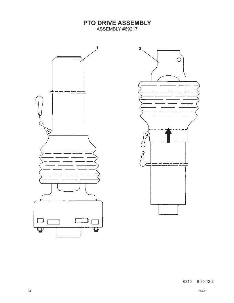
PTO DRIVE ASSEMBLY
6210 8-30-12-2
ASSEMBLY #69217
1 2
84 75421

6211 8-30-12-2
ITEM REQ’D PART NO. DESCRIPTION
1 1 70170 PTO Drive - Trencher Half Assembly - 61651 Replacement Friction Disk 2 1 70169 PRO Drive - Tractor Half Assembly
PTO DRIVE ASSEMBLYASSEMBLY #69217
75421 85
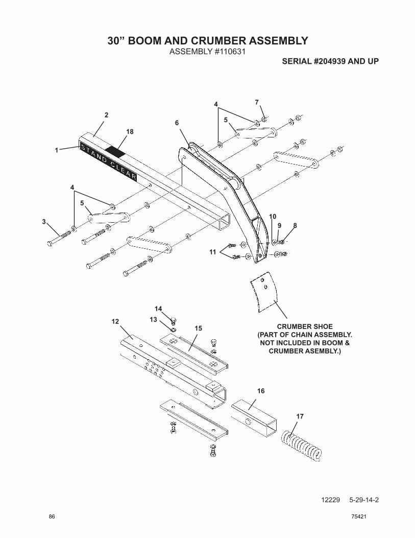
12229 5-29-14-2
1
18
2
3
6
5
4
7
8910
11
12 1314
15
16
17
CRUMBER SHOE(PART OF CHAIN ASSEMBLY. NOT INCLUDED IN BOOM &
CRUMBER ASEMBLY.)
30” BOOM AND CRUMBER ASSEMBLYASSEMBLY #110631
SERIAL #204939 AND UP
5
4
86 75421

12230 5-29-14-2
ITEM REQ’D PART NO. DESCRIPTION
1 2 41101 Decal - Stand Clear 2 1 89276 30” Crumber Bar / Restraint Bar 3 4 1101 .50” UNC X 4.50” Hex Capscrew 4 16 1646 .50” Hard Flat Washer 5 4 21061 Lever Arm
6 1 89278 Crumber End 7 4 1841 .50” UNC Deformed Lock Nut 8 1 1226 .38” UNC Hex Nut 9 2 1503 .38” Lock Washer 10 2 1514 .38” Flat Washer
11 2 1044 .38” UNC X 1.25” Hex Capscrew 12 1 53009 30” Boom 13 4 1505 .50” Lock Washer 14 4 1087 .50” UNC X .75” Hex Capscrew 15 2 53115 30” Wear Strip
16 1 53138 Boom Bushing 17 1 53188 Spring 18 1 50-0737 Decal - Pinch Point
30” BOOM AND CRUMBER ASSEMBLYASSEMBLY #110631
SERIAL #204939 AND UP
75421 87

5046 8-30-12-3
1
2
34
5 6
65
4
7
8
910
4
411
12
1314
15
13
16
17
CRUMBER SHOE(PART OF CHAIN ASSEMBLY. NOT INCLUDED IN BOOM &
CRUMBER ASEMBLY.)
30” BOOM AND CRUMBER ASSEMBLYSERVICE PARTS
UP TO SERIAL #204938
88 75421

5047 8-30-12-4
ITEM REQ’D PART NO. DESCRIPTION
1 2 40161 Decal - Stand Clear 2 1 53070 30” Crumber Bar / Restraint Bar 3 2 1536 .38” UNC Nylock Nut 4 8 1514 .38” Flat Washer 5 4 53038 Crumber Roller
6 4 53039 Crumber Roller Bushing 7 2 1054 .38” UNC X 3.75” Hex Capscrew 8 1 53087 Crumber End 9 2 1226 .38” UNC Hex Nut 10 2 1503 .38” Lock Washer
11 2 1044 .38” UNC X 1.25” Hex Capscrew 12 1 53009 30” Boom 13 2 53115 30” Wear Strip 14 4 1087 .50” UNC X .75” Hex Capscrew 15 4 1505 .50” Lock Washer 16 1 53188 Spring 17 1 53138 Boom Bushing
30” BOOM AND CRUMBER ASSEMBLYSERVICE PARTS
UP TO SERIAL #204938
75421 89

12231 5-29-14-2
1
18
2
3
6
5
4
7
89
10
11
12
1314
15
16
17
CRUMBER SHOE(PART OF CHAIN ASSEMBLY. NOT INCLUDED IN BOOM &
CRUMBER ASEMBLY.)
36” BOOM AND CRUMBER ASSEMBLYASSEMBLY #110632
SERIAL #204939 AND UP
5
4
90 75421

12232 5-29-14-2
ITEM REQ’D PART NO. DESCRIPTION
1 2 41101 Decal - Stand Clear 2 1 89276 36” Crumber Bar / Restraint Bar 3 4 1101 .50” UNC X 4.50” Hex Capscrew 4 16 1646 .50” Hard Flat Washer 5 4 21061 Lever Arm
6 1 89278 Crumber End 7 4 1841 .50” UNC Deformed Lock Nut 8 1 1226 .38” UNC Hex Nut 9 2 1503 .38” Lock Washer 10 2 1514 .38” Flat Washer
11 2 1044 .38” UNC X 1.25” Hex Capscrew 12 1 53010 36” Boom 13 4 1505 .50” Lock Washer 14 4 1087 .50” UNC X .75” Hex Capscrew 15 2 53116 36” Wear Strip
16 1 53138 Boom Bushing 17 1 53188 Spring 18 1 50-0737 Decal - Pinch Point
36” BOOM AND CRUMBER ASSEMBLYASSEMBLY #110632
SERIAL #204939 AND UP
75421 91

5048 8-30-12-3
1
2
34
5 6
65
4
7
8
910
4
411
12
13
14
15
13
16
17
CRUMBER SHOE(PART OF CHAIN ASSEMBLY. NOT INCLUDED IN BOOM &
CRUMBER ASEMBLY.)
36” BOOM AND CRUMBER ASSEMBLYSERVICE PARTS
UP TO SERIAL #204938
92 75421

5049 8-30-12-4
ITEM REQ’D PART NO. DESCRIPTION
1 2 40161 Decal - Stand Clear 2 1 53069 36” Crumber Bar / Restraint Bar 3 2 1536 .38” UNC Nylock Nut 4 8 1514 .38” Flat Washer 5 4 53038 Crumber Roller
6 4 53039 Crumber Roller Bushing 7 2 1054 .38” UNC X 3.75” Hex Capscrew 8 1 53087 Crumber End 9 2 1226 .38” UNC Hex Nut 10 2 1503 .38” Lock Washer
11 2 1044 .38” UNC X 1.25” Hex Capscrew 12 1 53010 36” Boom 13 2 53116 36” Wear Strip 14 4 1087 .50” UNC X .75” Hex Capscrew 15 4 1505 .50” Lock Washer 16 1 53188 Spring 17 1 53138 Boom Bushing
36” BOOM AND CRUMBER ASSEMBLYSERVICE PARTS
UP TO SERIAL #204938
75421 93

12233 5-29-14-2
1
2
24
3
6
5
4
4
7
89
10
11
12
13
13
14
15
16
17
1819
20
21
22
23
23
CRUMBER SHOE(PART OF CHAIN ASSEMBLY. NOT INCLUDED IN BOOM &
CRUMBER ASEMBLY.)
48” BOOM AND CRUMBER ASSEMBLYASSEMBLY #110633
SERIAL #204939 AND UP
5
4
94 75421

12234 5-29-14-2
ITEM REQ’D PART NO. DESCRIPTION
1 2 41101 Decal - Stand Clear 2 1 21045 48” Crumber Bar / Restraint Bar 3 4 1101 .50” UNC X 4.50” Hex Capscrew 4 20 1646 .50” Hard Flat Washer 5 4 21061 Lever Arm
6 1 89278 Crumber End 7 4 1841 .50” UNC Deformed Lock Nut 8 1 1226 .38” UNC Hex Nut 9 2 1503 .38” Lock Washer 10 2 1514 .38” Flat Washer
11 2 1044 .38” UNC X 1.25” Hex Capscrew 12 1 53011 48” Boom 13 8 1505 .50” Lock Washer 14 4 1087 .50” UNC X .75” Hex Capscrew 15 2 53117 48” Wear Strip
16 1 53138 Boom Bushing 17 1 53188 Spring 18 2 56417 Guide Tube 19 2 1981 .50” UNC X 6.50” Hex Capscrew GR8 20 2 1231 .75” UNC Hex Nut
21 2 1980 .50” UNC X 6.00” Hex Capscrew GR8 22 2 56416 Adjusting Stud 23 4 1228 .50” UNC Hex Nut 24 1 50-0737 Decal - Pinch Point
48” BOOM AND CRUMBER ASSEMBLYASSEMBLY #110633
SERIAL #204939 AND UP
75421 95

5050 8-30-12-4
1
2
34
5 6
65
4
7
8
910
4
411
12
13
14
15
13 16
17
CRUMBER SHOE(PART OF CHAIN ASSEMBLY. NOT INCLUDED IN BOOM &
CRUMBER ASEMBLY.)
1819
20
21
2223
15
24
22
24
21
23
15
48” BOOM AND CRUMBER ASSEMBLYSERVICE PARTS
UP TO SERIAL #204938
96 75421

5051 8-30-12-4
ITEM REQ’D PART NO. DESCRIPTION
1 2 40161 Decal - Stand Clear 2 1 53068 48” Crumber Bar / Restraint Bar 3 2 1536 .38” UNC Nylock Nut 4 8 1514 .38” Flat Washer 5 4 53038 Crumber Roller
6 4 53039 Crumber Roller Bushing 7 2 1054 .38” UNC X 3.75” Hex Capscrew 8 1 53087 Crumber End 9 2 1226 .38” UNC Hex Nut 10 2 1503 .38” Lock Washer
11 2 1044 .38” UNC X 1.25” Hex Capscrew 12 1 53011 48” Boom 13 2 53117 48” Wear Strip 14 6 1087 .50” UNC X .75” Hex Capscrew 15 8 1505 .50” Lock Washer 16 1 53188 Spring 17 1 53138 Boom Bushing 18 2 56417 Guide Tube 19 2 1981 .50” UNC X 6.50” Hex Capscrew GR 8 20 2 1231 .75” UNC Hex Nut
21 2 1980 .50” UNC X 6.00” Hex Capscrew GR 8 22 2 56416 Adjusting Stud 23 4 1228 .50” UNC Hex Nut 24 4 1646 .50” Flat Hard Washer
48” BOOM AND CRUMBER ASSEMBLYSERVICE PARTS
UP TO SERIAL #204938
75421 97
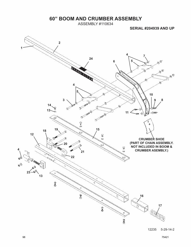
12235 5-29-14-2
12
24
3
6
5
4
4
7
89
10
11
12
13
13
14
15
16
17
18 19
20
2122
23
CRUMBER SHOE(PART OF CHAIN ASSEMBLY. NOT INCLUDED IN BOOM &
CRUMBER ASEMBLY.)
60” BOOM AND CRUMBER ASSEMBLYASSEMBLY #110634
SERIAL #204939 AND UP
5
4
98 75421

12236 5-29-14-2
ITEM REQ’D PART NO. DESCRIPTION
1 2 41101 Decal - Stand Clear 2 1 100261 60” Crumber Bar / Restraint Bar 3 4 1101 .50” UNC X 4.50” Hex Capscrew 4 20 1646 .50” Hard Flat Washer 5 4 21061 Lever Arm
6 1 89278 Crumber End 7 4 1841 .50” UNC Deformed Lock Nut 8 1 1226 .38” UNC Hex Nut 9 2 1503 .38” Lock Washer 10 2 1514 .38” Flat Washer
11 2 1044 .38” UNC X 1.25” Hex Capscrew 12 1 53012 60” Boom 13 8 1505 .50” Lock Washer 14 4 1087 .50” UNC X .75” Hex Capscrew 15 2 53118 60” Wear Strip
16 1 53138 Boom Bushing 17 1 53188 Spring 18 2 56417 Guide Tube 19 2 1981 .50” UNC X 6.50” Hex Capscrew GR8 20 2 1231 .75” UNC Hex Nut
21 2 1980 .50” UNC X 6.00” Hex Capscrew GR8 22 2 56416 Adjusting Stud 23 4 1228 .50” UNC Hex Nut 24 1 50-0737 Decal - Pinch Point
60” BOOM AND CRUMBER ASSEMBLYASSEMBLY #110634
SERIAL #204939 AND UP
75421 99

60” BOOM AND CRUMBER ASSEMBLY
5052 8-30-12-4
SERVICE PARTSUP TO SERIAL #204938
1
2
34
56
65
47
8
910
4
411
12
13
14
15
13
16
17
CRUMBER SHOE(PART OF CHAIN ASSEMBLY. NOT INCLUDED IN BOOM &
CRUMBER ASSEMBLY.)
18 19
20
21
2223
15
24
24
22
23
100 75421

5053 8-30-12-5
ITEM REQ’D PART NO. DESCRIPTION
1 2 40161 Decal - Stand Clear 2 1 53067 48” Crumber Bar / Restraint Bar 3 2 1536 .38” UNC Nylock Nut 4 8 1514 .38” Flat Washer 5 4 53038 Crumber Roller
6 4 53039 Crumber Roller Bushing 7 2 1054 .38” UNC X 3.75” Hex Capscrew 8 1 53087 Crumber End 9 2 1226 .38” UNC Hex Nut 10 2 1503 .38” Lock Washer
11 2 1044 .38” UNC X 1.25” Hex Capscrew 12 1 53012 60” Boom 13 2 53118 60” Wear Strip 14 8 1087 .50” UNC X .75” Hex Capscrew 15 10 1505 .50” Lock Washer 16 1 53188 Spring 17 1 53138 Boom Bushing 18 2 56417 Guide Tube 19 2 1981 .50” UNC X 6.50” Hex Capscrew GR 8 20 2 1231 .75” UNC Hex Nut
21 2 1980 .50” UNC X 6.00” Hex Capscrew GR 8 22 2 56416 Adjusting Stud 23 4 1228 .50” UNC Hex Nut 24 4 1646 .50” Flat Hard Washer
60” BOOM AND CRUMBER ASSEMBLYSERVICE PARTS
UP TO SERIAL #204938
75421 101

HEADSHAFT CARTRIDGE ASSEMBLY
6204 8-30-12-3
ASSEMBLY #60001
12
34
56 7
8
9
10
1112
1314
15
16
102 75421
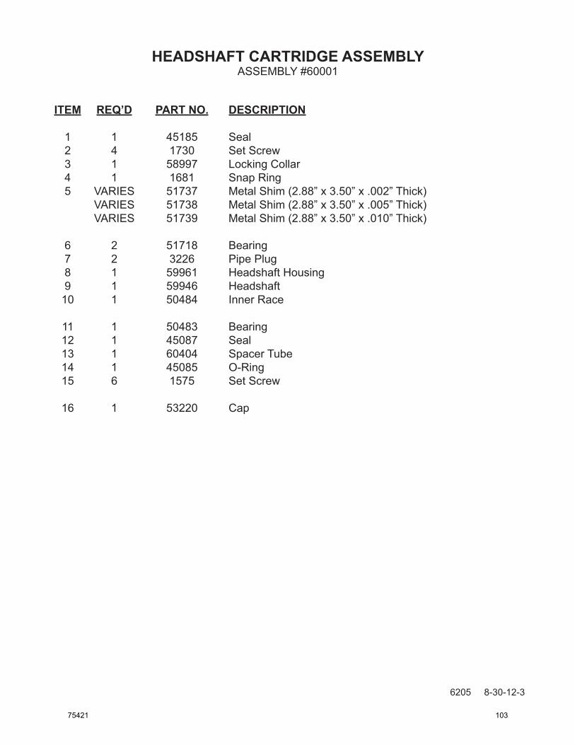
6205 8-30-12-3
ITEM REQ’D PART NO. DESCRIPTION
1 1 45185 Seal 2 4 1730 Set Screw 3 1 58997 Locking Collar 4 1 1681 Snap Ring 5 VARIES 51737 Metal Shim (2.88” x 3.50” x .002” Thick) VARIES 51738 Metal Shim (2.88” x 3.50” x .005” Thick) VARIES 51739 Metal Shim (2.88” x 3.50” x .010” Thick)
6 2 51718 Bearing 7 2 3226 Pipe Plug 8 1 59961 Headshaft Housing 9 1 59946 Headshaft 10 1 50484 Inner Race
11 1 50483 Bearing 12 1 45087 Seal 13 1 60404 Spacer Tube 14 1 45085 O-Ring 15 6 1575 Set Screw
16 1 53220 Cap
HEADSHAFT CARTRIDGE ASSEMBLYASSEMBLY #60001
75421 103

SPROCKET AND BOOM END SET
5056 8-30-12-4
12
3
4
56
7
8
9
10
118
104 75421

5057 8-30-12-4
ITEM REQ’D PART NO. DESCRIPTION
1 2 1230 .62” UNC Hex Nut 2 2 1506 .62” Lock Washer 3 2 1118 .62” UNC X 2.50” Hex Capscrew 4 1 53975 12 Tooth Drive Sprocket - 2.00” Pitch 5 1 80032 Boom End
6 1 1548 .75” UNC X 1.25” Nylock Capscrew 7 1 53132 1.12” Square Pin 8 2 54067 Idler Spacer 9 1 53988 Idler Bearing Hub 10 1 8085 Idler Bearing
11 1 79103 Idler Wheel
SPROCKET AND BOOM END SET
NOTES:(1) Idler Wheel #79103 replaces Idler Wheel #62718. Effective 6/19/92.
(1)
75421 105

20” AUGER ASSEMBLY
5066 8-30-12-3
ASSEMBLY #59000
1
2
3
4
106 75421

5067 8-30-12-3
ITEM REQ’D PART NO. DESCRIPTION
1 1 59001 Auger 2 3 1095 .50” UNC X 2.75” Hex Capscrew 3 3 1505 .50” Lock Washer 4 3 1228 .50” UNC Hex Nut
20” AUGER ASSEMBLYASSEMBLY #59000
75421 107