Embed Size (px)
Citation preview

TM 3-6665-225-12
TECHNICAL MANUALOPERATOR’S AND ORGANIZATIONAL MAINTENANCE MANUAL
ALARM, CHEMICAL AGENT, AUTOMATIC: PORTABLE,
MANPACK, M8 (NSN 6665-00-935-6955);FIXED EMPLACEMENT, M10 (NSN 6665-00-169-1446);
FOR TRUCK, UTILITY, 1/4 TON, M11(NSN 6665-00-169-1447);
FOR TRUCK, 3/4 TON, M12 (NSN 6665-00-169-1448);FOR TRUCK, 2 1/2 TON, M13 (NSN 6665-00-169-1449);
FOR FULL-TRACKED ARMORED PERSONNEL CARRIERS ANDRECOVERY VEHICLES, M14 (NSN 6665-00-169-1450);
FOR CARRIER, COMMAND AND RECONNAISSANCEARMORED, M15 (NSN 6665-00-169-1451);
W/POWER SUPPLY FOR TRUCK, UTILITY, 1/4 TON,M16 (NSN 6665-00-169-1452);
W/POWER SUPPLY FOR TRUCK, 3/4 TON,M17 (NSN 6665-00-169-1453); AND
W/POWER SUPPLY FOR TRUCK, 2 1/2 TON,M18 (NSN 6665-00-169-1454)
H E A D Q U A R T E R S , D E P A R T M E N T O F T H E A R M Y29 AUGUST 1975
This copy is a reprint which includes current
pages from Changes 1 and 2.

*TM 3-6665-225-12
TECHNICAL MANUAL HEADQUARTERSDEPARTMENT OF THE ARMY
No. 3-6665-225-12 WASHINGTON , DC, 29 August 1975
OPERATOR’S AND ORGANIZATIONAL MAINTENANCE MANUAL
ALARM, CHEMICAL AGENT, AUTOMATIC: PORTABLE,MANPACK, M8 (NSN 6665-00-935-6955);
FIXED EMPLACEMENT, M10 (NSN 6665-00-169-1446):FOR TRUCK, UTILITY, 1/4 TON, M11 (NSN 6665-00-169-1447);
C H A P T E R 1 .Section I.
II.C H A P T E R 2 .Section I.
II.III.
I V .
C H A P T E R 3 .Section I.
II.III.IV.V.
C H A P T E R 4 .Section I.
II.III.IV.V.
C H A P T E R 5 .Section I.
II.A PPENDIX A .A PPENDIX B .
FOR TRUCK, 3/4 TON, M12 (NSN 6665-00-169-1448);FOR TRUCK, 2 1/2 TON, M13 (NSN 6665-00-169-1449);
FOR FULL-TRACKED ARMORED PERSONNEL CARRIERS ANDRECOVERY VEHICLES, M14 (NSN 6665-00-169-1450);FOR CARRIER, COMMAND AND RECONNAISSANCE
ARMORED, M15 (NSN 6665-00-169-1451);W/POWER SUPPLY FOR TRUCK, UTILITY, 1/4-TON,
M16 (NSN 6665-00-169-1452);W/POWER SUPPLY FOR TRUCK, 3/4 TON,
M17 (NSN 6665-00-169-1453): ANDW/POWER SUPPLY FOR TRUCK, 2 1/2 TON,
M18 (NSN 6665-00-169-1454)Current as of June 1975
Paragraph
INTRODUCTIONGeneral 1-1D e s c r i p t i o n a n d d a t a 1-5OPERATING INSTRUCTIONSControls and instruments 2-1Operation under usual conditions 2-5Operation under unusual conditions 2-14
Daily log for M43 detector unit and pump assembly 2-19
OPERATOR’S MAINTENANCE INSTRUCTIONSInstallation 3-1Preventive maintenance checks and services 3-5Operator’s troubleshooting 3-7M43 detector unit 3-9M42 alarm unit 3-15ORGANIZATIONAL MAINTENANCE INSTRUCTIONSService upon receipt of materiel 4-1Organizational maintenance troubleshooting 4-3Monthly log for M43 detector unit 4-6M43 detector unit 4-8M42 alarm unit 4-11PREPARATION FOR SHIPMENT AND ADMINISTRATIVE STORAGEPreparation for shipment 5-1Administrative storage 5-3
Page
1-11-1
2-12-22-10
2 - 1 5
3-13-203-213-243-25
4-14-14-14-24-2
5-15-2
REFERENCES A-1BASIC ISSUE ITEMS LIST AND ITEMS TROOP INSTALLED OR AUTHORIZED
LIST B-1
*This manual supersedes TM 3-6665-225-12 , 20 March 1972, inc luding a l l changes .
Change 2 i

TM 3-6665–225–12
Paragraph Page
Section I. Introduction B-1II. Basic issue items list. Not applicable.
III. Items troop installed or authorized list B-2 —
A PPENDIX C . MAINTENANCE ALLOCATION CHART C-1Sect ion I . In t roduct ion C-1
II. Maintenance allocation chart for Alarm, Chemical Agent, Automatic: Portable: M8, M10through M18 C-3
III. Alarm, Chemical Agent, Automatic: Portable; M8, M10 through M18 C-6
ii Change 2

TM 3-6665-225–12
Fig. NO.
1-11-21-31-41-51-61-71-82-12-22-32-42-52-62-72-8
2 - 9
2 - 1 0
3-13-23-33-43-53-63-73-83-93-103-113-123-133-143-153-163-173-183-193-203-213-223-234-14-24-35-1
LIST OF ILLUSTRATIONS
Title
Major components of alarm systemsM43 detector unitDetector unit assemblyBottom case assemblyM42 alarm unitM229 refill kitBA3517/U batteryM43 detector unit air-solution flow diagramM43 detector unit controls and instrumentsM10 power supplyPreparing solutionInstalling air filterAIR INLET assemblyFLOWMETER applicationM43 detector unit employing a BB501/U battery and M168 cableRAIN SHIELD assembly application
Sample DA Form 2408-1 modified for use with M43 detector unit
Sample DA Form 2408-1 modified for use with pump assembly
M43 detector unit employing a BA3517/U batteryM43 detector unit employing an M10 power supplyM43 detector unit employing M42 alarm unit(s)Preparing rucksack for backpackingM43 detector unit and BA3517/U battery installed on a rucksackMl1 alarm system installed in a one-quarter-ton utility truckM12 alarm system installed in a three-quarter-ton truckM13 alarm system installed in a 2 1/2-ton truckM14 alarm system installed in a full-tracked personnel carrier and recovery vehicleM15 alarm system installed in an armored command and reconnaissance carrierM43 detector unit and BA3517/U battery installed in high profile mountM43 detector unit installed in high profile mountM43 detector unit installed in low profile mountM42 alarm unit installed in a 1/4-ton utility truckM42 alarm unit installed in a 3/4-ton truckRefill kit drawer installed in a 3/4-ton truckM42 alarm unit installed in a 2 1/2-ton truck
Page
1-21-41-51-61-71-81-81-92-22-32-52-62-62-72-122-13
2-16
2-18
3-23-33-43-63-73-83-83-93-93-103-113-123-133-143-153-163-16
M42 alarm unit and a BA3517/U battery installed in an armored personnel carrier and recovery vehicle 3-17Refill kit drawer installed in an armored personnel carrier and recovery vehicle 3-18M42 alarm unit installed in an armored command and reconnaissance vehicle 3-19BA3517/U battery installed in an armored reconnaissance vehicle 3-20M43 detector unit modular components 3-24M42 alarm unit battery installation 3-26Sample DA Form 2408-1 modified for recording monthly log 4-2RAIN SHIELD assembly and flow rate meter components 4-3M42 alarm unit, exploded view 4-4Shipping guard fabrication and installation diagram 5-2
Change 2 i i i

TM 3-6665-225-12
CHAPTER 1
INTRODUCTION
Section I. GENERAL
1-1. ScopeThese instructions are for use by the operator andorganizational maintenance personnel. They applyto the following 10 alarms, later referenced asalarm systems:
a. Alarm, Chemical Agent, Automatic: Portable,Manpack, M8.
b. Alarm, Chemical Agent, Automatic: Portable,Fixed Emplacement, M10.
C. Alarm, Chemical Agent, Automatic: Portable forTruck, Utility, 1/4 Ton, M11.
d. Alarm, Chemical Agent, Automatic: Portablefor Truck, 3/4 Ton, M12
e. Alarm, Chemical Agent, Automatic: Portable forTruck, 2 1/2 Ton, M13.
f. Alarm, Chemical Agent, Automatic: Portablefor Full Tracked Personnel Carrier and RecoveryVehicles, M14.
g. Alarm, Chemical Agent, Automatic: Portablefor Carrier, Command and Reconnaissance, Ar-mored, M15.
h. Alarm, Chemical Agent, Automatic: Portable,W/Power Supply, for Truck, Utility, 1/4 Ton, M16.
i. Alarm, Chemical Agent, Automatic: Portable,
W/Power Supply for Truck, 3/4 Ton, M17.j. Alarm, Chemical Agent, Automatic: Portable,
W/Power Supply, for Truck 2 1/2 Ton, M18.1-2. Record and Report Forms
a. Department of the Army forms and proce-dures used for equipment maintenance will bethose prescribed by TM 38-750. The modificationand use of DA Form 2408-1 is described in para-graphs 2-19, 2-20, and 4-7.
b. You can improve this manual by recommen-ding improvements using DA Form 2028 (Recom-mended Changes to Publications and Blank Forms)or DA Form 2028-2 (test) located in the back of thismanual. Mail the form direct to Commander, USArmy Armament Materiel Readiness Command,Attn: DRSAR-MAS-C, Aberdeen Proving Ground,MD 21010. A reply will be furnished direct to you.1-3. Administrative StorageRefer to TM 740-90-1 and chapter 5 for administra-tive storage instructions on the alarm systems.1-4. Destruction to Prevent Enemy UseRefer to TM 43-0002-31 for procedures for destruc-tion of equipment to prevent enemy use.
Section II. DESCRIPTION AND DATA
1-5. GENERALEach alarm system detects very low concentrationsof chemical-agent vapors or inhalable aerosols andautomatically signals the presence of chemicalagents. The equipment may be operated continu-ously but must be serviced every 12 hours.1-6. Major components and Associated
Equipment(fig. 1-1)
The following major components and associa-ted equipment are combined tosystems:
a. Detector Unit, ChemicalAlarm: M43.
b. Alarm Unit, ChemicalAlarm: M42.
C. Refill kit, Chemical AgentM229.
d. Battery, Dry, Medium Duty,
form the 10 alarm
Agent Automatic
Agent Automatic
Automatic Alarm:
36V: BA3517/U.e. Battery, Dry, 1 1/2V: BA3202/UF or Battery,
Dry, 1 1/2V: BA3030.f. Power Supply, Chemical Agent Automatic
Alarm: M10.g. Installation Kits (Each adapts a particular
vehicle to a mounting kit.)h. Mounting Kit, Chemical Agent Automatic
Alarm: High Profile, M228 or Mounting Kit,Chemical Agent Automatic Alarm: Low Profile,M182.
i. Telephone cable, type WD1TT.j. Winterization Kit, Automatic Chemical Agent
Alarm: M253.k. Rucksack and shelf.
1-7. System ConfigurationsNOTE
An Asterisk indicates an expendable item(table 1-3).
a. M8 Alarm System. The M8 alarm system is forhand-carry or backpack operations. It consists ofthe following equipment:
Change 2 1-1

TM 3-6665-225-12
Figure 1-1. Major components of alarm systems.
1-2

TM 3-6665-225-12
(1) One M43 detector unit.(2) One M42 alarm unit.(3) *One M229 refill kit.(4) *One BA3517/U battery.(5) *Four BA3030 batteries.
b. M10 Alarm System. The M10 alarm systemis used at fixed emplacement installation. It con-sists of the following equipment:
(1) One M43 detector unit.(2) One M42 alarm unit.(3) *One M229 refill kit.(4) *One BA3517/U battery.(5) *Four BA3030 batteries.(6) One M10 power supply.
c. M11, M12, and M13 Alarm Systems. Thesethree systems are used on selected wheeled ve-hicles. The M11 alarm system is used on a 1/4-tonutility truck, the M12 alarm system is used on a3/4-ton truck, and the M13 alarm system is usedon a 2 1/2-ton truck. The installation kit suppliedin each system mechanically and electricallyadapts the vehicle to accept an M228 high profilemounting kit. The high profile mount suppliedsecures the M43 detector unit and the BA3517/Ubattery to a front fender of the vehicle. Eachalarm system consists of the following equipment:
(1) One M43 detector unit.(2) One M42 alarm unit.(3) *One M229 refill kit.(4) *One BA3517/U battery.(5) *Four BA3030 batteries.(6) One applicable installation kit.(7) One M228 mounting kit.
d. M14 and M15 Alarm Systems. The M14 andM15 alarm systems are for selected full-tracked-vehicle installations. The M14 alarm system isused on full-tracked personnel carriers andrecovery vehicles, and the M15 alarm system isused on command and reconnaissance armoredcarriers. The installation kit supplied in each sys-tem mechanically and electrically adapts thevehicle to accept an M182 low profile mountingkit. The low profile mount supplied secures theM43 detector unit to the front of the vehiclewithout disrupting the basic silhouette of thevehicle. Each alarm system consists of the fol-lowing equipment.
(1) One M43 detector unit.(2) One M42 alarm unit.(3) *One M229 refill kit.(4) *One BA3517/U battery.(5) *Four BA 3030 batteries. (6) One applicable installation kit.(7) One M182 mounting kit.
e. M16, M17, and M18 Alarm Systems. Thesethree alarm systems are used on selected wheeled
vehicles. Each includes an M10 power supply foruse when the M43 detector is removed from thevehicle for temporary fixed operation at theorganization site. The M16 alarm system is usedon a 1/4-ton utility truck, the M17 system is usedon a 3/4-ton truck, and the M18 alarm system isused on a 2 1/2 ton truck. The installation kitsupplied in each system mechanically and elec-trically adapts the vehicle to accept an M228 highprofile mounting kit. The high profile mountsupplied secures the M43 detector unit and theBA3517/U battery to a front fender of the vehicle.Each alarm system consists of the followingequipment:
(1) One M43 detector unit,(2) One M42 alarm unit.(3) *One M229 refill kit.(4) *One BA3517/U battery.(5) One M10 power supply.(6) *Four BA3030 batteries.(7) One applicable installation kit.(8) One M228 mounting kit.
1-8. Items Troop Installed or AuthorizedIn addition to the equipment supplied as part ofeach alarm system, additional items are author-ized to the operator to complete the system con-figuration.
a. Rucksack and Shelf. When the M8 alarmsystem is used in the backpack configuration, theoperator is authorized a rucksack and shelf.
b. Telephone Cable. The operator is authorizedand must requisition two-conductor, telephonecable to connect the M42 alarm unit wheninstalling the M8 and M10 alarm systems. Tele-phone cable must also be used when connectingadditional M42 alarm units in all alarm systems.
c. M253 Winterization Kit. The operator is au-thorized to requisition an M253 winterization kitfor operating the M8 and M10 alarm systems intemperatures below +20ºF. The M253 winteriza-tion kit consists of two BB501/U batteries andone M168 cable.
(1) BB501/U battery. The BB501/U batteryis a rechargeable, heavy-duty, nickel-cadmiumbattery.
(2) M168 cable. The M168 cable connects theBB501/U battery to the M43 detector or the M10power supply. The cable is 50 inches long and isterminated at one end with an SCL-6028/4-3connector and at the other end with aPT05A-14-5P or KPT47024-311 connector.1-9. M43 Detector UnitThe M43 detector unit senses the presence ofchemical agents in the air and produces an audiblesignal. The M43 detector unit consists of adetector unit assembly (6, fig. 1-2) secured to a
1-3

TM 3-6665-225–12
bottom case assembly (9) by four clampingcatches (12).
a. Detector Unit Assembly. Attached to thedetector unit assembly (6) are a handle (1), a horn(2), a BATTERY TEST switch and HORN VOLcontrol (3), an AIR INLET assembly (4), a ZEROADJUST knob (5), and AIR FILTER plug (7), anelectrical connector cover (10), two chains (8) thatattach the AIR FILTERcover, a 24 VDC INPUTclamping catches (12), four
plug and connectorreceptacle (11), fourbottom catches (13),
two strap fastener loops (14), an AIR OUTLETcap (15), an identification plate (16), two RE-MOTE binding posts (17), a meter (18), and handcrank (19). The handle (2, fig. 1-3) contains aRAINSHIELD assembly (1) and a FLOW-METER (3). A chassis (4) is mounted to theunderside of the detector unit assembly. Mountedto the chassis (4) are four electrical contacts (5); apump assembly (7), secured by two catches (6); adetector cell (8), secured by a bail (9); anelectronic module (10), secured by a turnlock
Figure 1-2. M43 detector unit.
1-4

fastener (11); and a reservoir assembly (12), whichscrews into the chassis (4).
b. Bottom Case Assembly. Mounted to theoutside of the bottom case assembly (9, fig. 1-2)are an instruction plate (3, fig. 1-4); two catches(4) that attach a BA3517/U battery; and fourclamping catches (5) that secure the bottom caseassembly to the detector unit assembly. A seal (1)fits in a groove around the top of the bottom caseassembly to insure that the interior of the M43detector unit is watertight and airtight when thebottom case assembly is secured to the detectorunit assembly. Electrical resistance heaters areembedded in the double-walled case of the bottomcase assembly. Two pairs of heater contacts (2)
1-5
TM 3-6665-225-12
mate with contacts (5, fig. 1-8) in the detector as-sembly. When the M43 detector unit is operatedbelow 40ºF., the heaters are automatically turnedon and off to maintain 40ºF. within the bottomcase assembly.1-10. M42 Alarm UnitThe M42 alarm unit, when connected to the M43detector unit provides a remote audible and visualsignal or visual signal only whenever the M43detector unit senses chemical agent. The M42alarm unit consists of a panel (1, fig. 1-5) securedto a housing (4) by four knurled screws (9). Thepanel contains an ALARM-RED indicator (3), aloudspeaker (5), an identification plate (6), twobinding posts (7), and a selector switch (8). Two
1 RAINSHIELD assembly 9 Bai l2 Handle 10 Electronic module3 FLOWMETER 11 Turnlock fastener4 Chassis 12 Reservoir assembly5 Contact 12.1 Weight assembly6 Catch 13 Rainshield7 Pump assembly 14 Adapter8 Detector cell
Figure 1-3. Detector unit assembly.

TM 3-6665-225-12
Figure 1-4. Bottom case assembly.
D-rings (2) are fastened to the housing (4). FourBA3030 batteries are secured in the housing.
1-11. M10 Power SupplyThe M10 power supply (3, fig. 1-1) requires inputpower of 115 or 220 volts at 50, 60, or 400 Hertz,found at fixed installations, and produces anaverage output of 29.5 volts dc. Additionaldescriptive data on the M10 power supply is inTM 3-6665-261-14.
1-12. Mounting Kitsa. A4228 Mounting Kit. The M228 mounting
kit is used to electrically connect and mount theM43 detector unit and the M42 alarm unit to awheeled vehicle. The kit consists of a high profilemount (8, fig. 1-1) and an alarm unit mountingbracket (9). The high profile mount consists of anelectrical cable assembly and an inner wrap as-sembly that is shock mounted to an outer wrapassembly by s ix res i l ient mounts . TM3-6665-273-20 describes the M228 mounting kit.
b. M182 Mounting Kit. The M182 mountingkit is used to electrically connect and mount theM43 detector unit and M42 alarm unit to atracked vehicle. The kit consists of a low profilemount (10, fig. 1-1) and an alarm unit mountingbracket (9). The low profile mount consists of an
1-6
electrical cable assembly and an outer wrap as-sembly, and an inner wrap assembly. Six resilientmounts shock mount the inner wrap assembly tothe outer wrap assembly. TM 3-6665-273-20describes the M182 mounting kit.
1–13. Installation KitsEach installation kit mechanically and electricallyadapts a specific vehicle to accept an M43 detec-tor unit, an M42 alarm unit, an M228 or M182mounting kit, and in some cases, refill kit compo-nents and a BA3517/U battery. TM 3-6665-274-20 describes the installation kits.
1-14. M229 Refill Kit(fig. 1-6)
The M229 refill kit contains materials for 15 daysof continuous operation. The kit consists of asleeve (4), two drawers (1), and a plastic strap (2)that is discarded when the refill kit is first opened.The sleeve (4) and the drawers (1) are constructedof water-resistant corrugated fiberboard. Theexpiration date of the kit is marked on the sleeve(4). Each drawer (1) contains 15 solution reser-voirs (5), one sensitivity check bottle (6), and 30air filter packages (7). Each air filter package con-sists of an air filter (10), a plastic wrapper (9) inwhich the air filter is enclosed, and a watertight

TM 3-6665-225-12
1 Panel 4 Housing 7 Binding posts2 D-ring 5 Loudspeaker3 ALARM-RED indicator
8 Selector switch6 Identification plate 9 screw
Figure 1-5. M42 alarm unit.
bag (8) in which the plastic wrapper containingthe air filter is sealed. Each drawer is providedwith a handle (3).
1-15. BA3517/U BatteryThe BA3517/U battery supplies primary power tothe M43 detector unit when the alarm system ishand-carried or backpacked. When the alarm sys-tem uses an M10 power supply as a primary dcpower source, the BA 3517/U battery isconnected as a standby power source. The BA3517/U battery (fig. 1-7) has a plastic case, metalstrap (1), clamping catch (3), identification plate(2), and cable assembly (4).
1-16. Functional Description(fig. 1-8)
Air is drawn into the M43 detector unit throughthe AIR INLET (1) and passes through a temper-ature-controlled heater (2). The heater (2) insuresthat the temperature of the air sample, nextapplied to the air filter (3), is not below 90ºF. Theair filter (3) removes foreign particles before thesample is processed in the detector cell (4).Solution is pumped from the reservoir (5) into thedetector cell (4) by the pump assembly (6). The airsample combines with the solution within the
detector cell (4). An electrical signal produced bythe cell is monitored by the electronic module ofthe M43 detector unit. The air-solution mixer ispumped out of the detector cell (4) back into thereservoir (5) where the air and solution separate.Next, the pump assembly (6) draws the air fromthe reservoir (5) and exhausts it through the AIROUTLET heater (7) into the atmosphere. TheAIR OUTLET heater automatically heats theAIR OUTLET to prevent icing. Solution drawnfrom the reservoir (5) is scrubbed of impurities inthe detector cell (4) as it is recirculated by thepump assembly (6). When an air sample contain-ing chemical agent is mixed with solution, thedetector cell-electrical output increases, and theelectronic module turns on the horn and turns offthe pump assembly. The horn will sound until theoperator either resets the M43 detector unit ordisconnects the power source. When the hornsounds, the electronic module also provides atrigger signal to the REMOTE binding posts (17,fig. 1-2). If an M42 alarm unit (2, fig. 1-1) isconnected to the REMOTE binding posts, theM42 alarm unit also provides a warning signal.
1-17. Tabulated Dataa. Table 1-1 lists dimensions and weights of
1-7

TM 3-6665-225-12
Figure 1-6. M229 refill kit
alarm system components.b. Table 1-2 lists the maximum number of 12-hour
missions that a BA3517/U battery (7, fig. 1-1) can beused or a BB501/U battery (4) can be used beforerecharging. The maximum number of usable missionsfor each battery is tabulated as a function of the
average air temperature in which the battery is oper-ated.
c. Table 1-3 is a list of authorized consumable sup-plies and material required for operation of the equip-ment.
Figure 1-7. BA3517/U battery.
d. Operating and performance characteristics ofcomponents are as follows:
(1) M43 detector unit.Power requirements. . . . . . . . . . . . . . . . . . . . . . . . . . . . 18 to 39 VdcEnvironmental operating limits
Temperature. . . . . . . . . . . . . . . . . . . . . . . . . . . . -40ºF. to 120ºF.Humidity . . . . . . . . . . . . . . . . . . . . . . . . . . . . . . . . . . . .up to 100%
(2) M42 alarm unit.Power requirements . . . . . . . . . . . . . . . . . . . . . . . . . . . . . . . . . .6 VdcEnvironmental operating limits
Temperature . . . . . . . . . . . . . . . . . . . . . . . . . . . . -40ºF. to 120ºF.Humidity . . . . . . . . . . . . . . . . . . . . . . . . . . . . . . . . . . . .up to 100%
(3) M10 power supply. Refer to TM 3-6665-261-14.(4) BB501/U battery. Refer to TM 11-6140-203-15-3
(Under revision).(5) BA3517/U battery.
Type. . . . . . . . . . . . . . . . . . . . . . . . . . . . . . . . . . . Manganese-alkalineEnvironmental operating limits
Temperature. . . . . . . . . . . . . . . . . . . . . . . . . . . . .20ºF. to 120ºF.Humidity . . . . . . . . . . . . . . . . . . . . . . . . . . . . . . . . . . . .up to 100%
Operating life . . . . . . . . . . . . . . . . . . . . . . . . . . . . . . . . .See table 1-2
1-8 Change 1

TM 3-6665-225-12
Figure 1-8. M43 detector unit air-solution flow diagram.
Change 1 1-9

TM 3-6665-225-12
Table 1-1 Dimensions and Weights
Table 1-2. Battery Missions vs Air Temperature
Table 1-3. Consumable Supplies and Material
The supplies and material listed in this table are required for operation and maintenance of this equipment and arc authorized to be requisi-tioned by CTA 50-970, Expendable Items: Common Table of Allowances
1-10 Change 2

TM 3-6665-225-12
CHAPTER 2
OPERATING INSTRUCTIONS
2–1. GeneralThis section describes the controls and instru-ments of the M43 detector unit, M42 alarm unit,and M10 power supply.
2–2. M43 Detector Unita. Controls.
(1) Hand crank. The hand crank (2, fig. 2-1),located on top of the M43 detector unit is usedto manually prime the fluid system of the M43detector unit. It has a storage (up) position andan operational (down) position.
(2) AIR INLET assembly. The AIR INLETassembly (4) is located near the lower-right-frontcorner of the top. When in the open position, aircan be drawn into the M43 detector unit forsampling.
(3) ZERO ADJUST knob. T h e Z E R OADJUST knob (5) is located in the center-frontportion of the top. The knob is used to set theM43 detector unit during preoperational andoperational procedures and to reset the unit afteran alert has been sounded.
(4) HORN VOL-BATTERY TEST knob.The HORN VOL-BATTERY TEST knob (6) islocated in the center of the M43 detector unit top.When the knob is rotated, the horn output levelvaries from minimum (LO) to maximum (HI).Pressing in the knob connects the power source tothe meter (1).
b. Instruments.(1) Meter. The meter (1) is located on the top
of the unit. It provides a visual indication of thepower source voltage when the HORN VOL-BATTERY TEST knob (6) is pressed. Also, themeter is used when setting the ZERO ADJUSTknob (5).
(2) Horn. The horn (3) is located in theupper-right hand comer of the M43 detector unit.The horn provides an audible signal when thedetection circuits of the unit are activated.
(3) FLOWMETER. The FLOWMETER (3,fig. 1-3) is stored in the handle (2) of the M43detector unit. It is used to indicate the flow rate ofair drawn into the AIR INLET assembly (4, fig.2-1).
2-3. M42 Alarm Unita. Control. The M42 alarm unit contains a
Section I. CONTROLS AND INSTRUMENTS
three-position rotary selector switch (8, fig. 1-5)which allows manual selection of TEST HORNOFF, or HORN ON. To operate in the HORNOFF or HORN ON position, the M42 alarm unitmust be connected to an operating M43 detectorunit.
(1) TEST position. In the TEST position,the ALARM-RED indicator will flash and theloudspeaker will sound. This is a functional testof the M42 alarm unit.
(2) HORN OFF position. In this operationalposition, when the M43 detector unit signals analarm, only the ALARM-RED indicator willflash.
(3) HORN ON position. When the M43alarm unit signals an alarm, and the selectorswitch of the M42 alarm unit is in the HORN ONposition, the ALARM-RED indicator will flash,and the loudspeaker will sound.
b. Instruments.(1) Loudspeaker. The loudspeaker (5, fig.
1-5) is located on the panel (1). It provides anaudible signal during test and operation of thealarm system.
(2) ALARM-RED indicator. The ALARM- RED indicator (3) is located on the panel (1).When activated during test or during operation, itflashes a visual warning.
2-4. M10 Power Supplya. Control. The power switch (3, fig. 2-2) on
the panel assembly (6) controls the application ofac power to the M10 power supply. The powerswitch (3) has three positions:
(1) 115V. Used for power input of 115 vac.(2) OFF. Used to open input power circuit.(3) 220V. Used for power input of 220 vac.
b. Instruments. The M10 power supply has aPOWER ON indicator (2) and an annunciator (8)on its panel assembly (6).
(1) POWER ON indicator. The POWER ONindicator (2) lights when the M10 power supply isproviding dc power.
(2) Annunciator. The annunciator (8) is anelectrically-operated, manually-reset indicator.When the M10 power supply is operating from a110-volt or 220-volt ac power source, the annunci-ator indication is all white. If a standby battery is
2-1

TM 3-6665-225-12
Figure 2-1. M43 detector unit controls and instruments.
connected and the ac power source is dis- to OFF, the annunciator shows a black/whiteconnected, or if the power switch (3) is positioned indication.
Section II. OPERATION UNDER USUAL CONDITIONS
2-5. GeneralThis section contains instructions for inspecting,preparing, testing, and placing the alarm systemequipment into operation under usualenvironmental conditions. Usual environmentalconditions are defined as ambient air temperatureabove 40ºF., no precipitation, and no apparentpresence of blowing dust or sand. For operation intemperatures below 40ºF.; in rain, sleet, or snow;or in blowing dust or sand; refer to paragraphs2-15 through 2-17 for special instructions foroperation under unusual conditions.
NOTEIf the alarm system is to be operational
for two or more continuous missions,perform checks and reservicing pro-cedures (para 2-10) after each 12-hourmission.
2–6. Preoperational ProceduresThese procedures prescribe mandatory equipmentinspections prior to preparing the equipment foroperation.
NOTEInspect exterior of M43 detector unit forcracks or breaks and loose or missingparts. Turn in a unit suspect of damageor inability to operate properly becauseof visible deficiencies.
2-2

TM 3-6665-225-12
Figure 2-2. M10 power supply.
a. M43 Detector Unit.(1) Check that RAINSHIELD assembly (1,
fig. 1-3) and FLOWMETER (3) are not damagedand are installed in handle (2).
(2) Release four clamping catches (12, fig.1-2) and remove detector unit assembly (6) frombottom case assembly (9). Place detector unitassembly (6) on its side with AIR FILTER plug(7) up.
(3) Check that bottom case assembly con-tacts (2, fig. 1-4) and meeting contacts (5, fig.1-3) on detector unit assembly are not corroded,broken, or bent.
(4) Check that detector cell (8, fig. 1-3) issecurely installed.
(5) For new equipment, install detector cellas follows:
(a) Remove strap from bail (9).(b) Remove detector cell can from handle.(c) Remove detector cell from can.(d) Remove plastic bag, two caps, and
plug.(e) Dampen outside of two detector cell
ports with a few drops of water.(f) Position detector cell (8) so that its
ports are alined with their corresponding fittingsin chassis (4). Press detector cell into place inchassis.
(g) Center bail (9) on the bottom ofdetector cell (8) and turn lobed nut clockwise until
fingertight.(6) Verify that catches (6) of pump assem-
bly (7) are secured.(7) Check that turnlock fastener (11) of
electronic module (10) is locked in position.(8) Install detector unit assembly (6, fig.
1-2) in bottom case assembly (9) and secure fourclamping catches (12).
b. M42 Alarm Unit
NOTENotify personnel within audible rangethat test of the M42 alarm unit is to bemade.
(1) Position selector switch (8, fig. 1-5) toTEST. If M42 alarm unit is operative, loud-speaker (5) will sound, and ALARM-RED indica-tor (3) will flash.
(2) If M42 alarm unit does not operate inTEST mode, install fresh batteries (para 3-16).Repeat (1) above.
(3) Position selector switch (8) to HORNOFF.
c. M10 Power Supply(1) Unbuckle strap (5, fig. 2-2), unwind
STANDBY BATTERY cable (W3) (1), DETEC-TOR POWER cable (W2) (7), and 115V/220Vcable (W1) (9) from handle (4).
(2) Connect 115V/220V cable (W1) (9) topower source.
2-3

TM 3-6665-225-12
(3) Set power switch (3) to either 115V or220V position, determined by input voltage towhich M10 power supply is connected. POWERON indicator (2) must light.
(4) Set annunciator (8) to its “all white”position by turning it fully clockwise. Then rotateannunciator full counterclockwise.
(5) Position power switch (3) to OFF.(6) Disconnect 115V/220V cable (9) from
power source.d. M229 Refill Kit
(1) Check date on M229 refill kit sleeve (4,fig. 1-6). Discard M229 refill kit with expireddate.
(2) Check that each reservoir assembly (5) isfilled to above line on container. Check that liquidin reservoir assembly (5) is clear, not discolored orcontaminated. Discard defective reservoir assem-blies in M229 refill kit. Check that sensitivitycheck bottle (6) contains enough liquid for mis-sion.
(3) Check contents of M229 refill kit toassure that enough reservoir assemblies (5) andair filters (10) are available for the mission.
e. Battery power sources(1) BA3517/U battery (7, fig. 1-1). Inspect
BA3517/U battery for bent or broken connectorpins that could prevent proper electrical connec-tion and frayed or broken cable assembly insula-tion. Inspect the case for damage, such as cracks,that could prevent proper use of battery. ReplaceBA3517/U battery if suspect of damage.
(2) BB501/U battery and M168 cable (4and 6, fig. 1–1). Inspect and service BB501/Ubattery in accordance with TM 11-6140-203-15-3. Inspect M168 cable for bent or broken con-nector pins, frayed or broken cable assembly in-sulation, and other damage that could preventproper electrical connection and use of battery.Replace discharged or defective BB501/U batterywith freshly charged battery and replace M168cable assembly if suspect of damage.
f. Mounting Kit. If a mounting kit is part ofthe system configuration, check that vehicularmounting components are secure. Check cablesfor damage (cuts, chafed insulation, exposedwires ) and secure connections. Return vehicles toorganizational maintenance that have loosemounting kit components and cables that are sus-pect of damage.
2-7. Pre-Startup ProceduresThese procedures prescribe the method of pre-paring and installing the solution reservoir assem-bly and installing the air filter in the M43 detec-tor unit.
2-4
CAUTIONBefore airdrop operations, empty theliquid from the M43 detector unit rese-rvoir assembly. Internally splashingliquid may cause the M43 detector unitto become inoperative and cause themission to be aborted. Do not performthe following procedures until after theairdrop.
a. Remove one solution reservoir assembly (5,fig. 1-6) from drawer (1) of the M229 refill kit.
b. Prepare solution as described in figure 2-3.c. Install Reservoir Assembly.
(1) Release four clamping catches (12, fig.1-2) from catches (13) and remove detector unitassembly (6) from bottom case assembly (9).
WARNINGSolution in reservoir assembly iscaustic. Avoid contact with eyes andmouth. Flush from skin with water.
CAUTIONKeep weight assembly (12.1, fig. 1-3)free from dirt after removing reservoirassembly.(2) Hold detector unit assembly upright by
its handle (2, fig. 1-3) and unscrew reservoirassembly (12) counterclockwise. Allow weightassembly (12.1) to hang down. Discard usedreservoir assembly (12) in accordance withstanding operating procedures.
(3) Remove and discard cap from preparedsolution reservoir assembly.
(4) Center new reservoir assembly underweight assembly and screw reservoir assemblyclockwise into mounting hole in detectorassembly. Insure tight seal by turning reservoirD-ring clockwise.
NOTEIf the M43 detector unit is to be back-packed, position bottom case assembly(9, fig. 1-2) so that instruction plate (3,fig. 1-4) is on side opposite 24 VDC IN-PUT receptacle (11, fig. 1-2).
(5) Check that seal (1, fig. 1-4) is completelyseated in groove around top of bottom caseassembly. Assemble detector unit assembly (6,fig. 1-2) to bottom case assembly (9) and secureclamping catches (12).
d. Install Air FilterNOTE
If air filter has been installed in M43detector unit for less than 24 hours,remove one air filter package (7, fig.1-6), disregard (1) through (5) below,and proceed to paragraph 2-8.

TM 3-6665–225–12
Figure 2-3. Preparing solution.
(1) If air filter has been in the M43 detectorunit for 24 hours or more, or if no air filter is inplace, remove two air filter packages (7) fromM229 refill kit. Also remove sensitivity checkbottle (6).
NOTEOne air filter will be used during startup(para 2-9) and one will be used duringmission.
(2) Unscrew AIR FILTER plug (4, fig. 2-4).Remove and discard air filter (3) from M 43detector unit.
(3) Open and discard watertight bag (8, fig.1-6). Remove air filter (10) from plastic wrapper(9) and discard plastic wrapper.
(4) Insert air filter (3, fig. 2-4) into AIRFILTER slot of M43 detector unit (1) with blackside of filter material (2) upward.
2-5
TM 3-6665-225-12
Figure 2-4. Installing air filter.
(5) Install and tighten AIR FILTER plug(4).
2-8. Installing Equipment as a SystemThe remaining procedures require that the alarmsystem be installed in accordance with the appro-priate instructions in paragraphs 3-1 and 3-4.
NOTEDo not connect power to M43 detectorunit 24 VDC INPUT connector (11, fig.1-2) until instructed to do so.
2–9. Startup and OperationThese procedures start and place the alarmsystem into operation.
a. Remove AIR OUTLET cap (15, fig. 1-2)from AIR OUTLET port. Remove cover (10) from24 VDC INPUT connector (11).
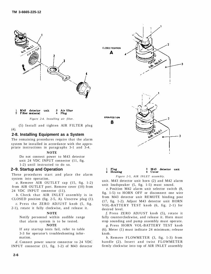
b. Check that AIR INLET assembly is inCLOSED position (fig. 2-5, A). Unscrew plug (1).
c. Press the ZERO ADJUST knob (5, fig.2-1), rotate it fully clockwise, and release it.
NOTENotify personnel within audible rangethat alarm system is to be tested.
NOTEIf any startup tests fail, refer to table3-3 for operator’s troubleshooting infor-mation.
d. Connect power source connector to 24 VDCINPUT connector (11, fig. 1-2) of M43 detector
Figure 2-5, AIR INLET assembly.
unit. M43 detector unit horn (2) and M42 alarmunit loudspeaker (5, fig. 1-5) must sound.
e. Position M42 alarm unit selector switch (8,fig. 1-5) to HORN OFF or disconnect one wirefrom M43 detector unit REMOTE binding post(17, fig. 1-2). Adjust M43 detector unit HORNVOL-BATTERY TEST knob (6, fig. 2-1) fordesired level.
f. Press ZERO ADJUST knob (5), rotate itfully counterclockwise, and release it. Horn muststop sounding and pump assembly must operate.
g. Press HORN VOL-BATTERY TEST knob(6). Meter (1) must indicate 24 minimum; releaseknob.
h. Remove FLOWMETER (3, fig. 1-3) fromhandle (2). Insert and twist FLOWMETERfirmly clockwise into top of AIR INLET assembly
2-6
TM 3-6665-225-12
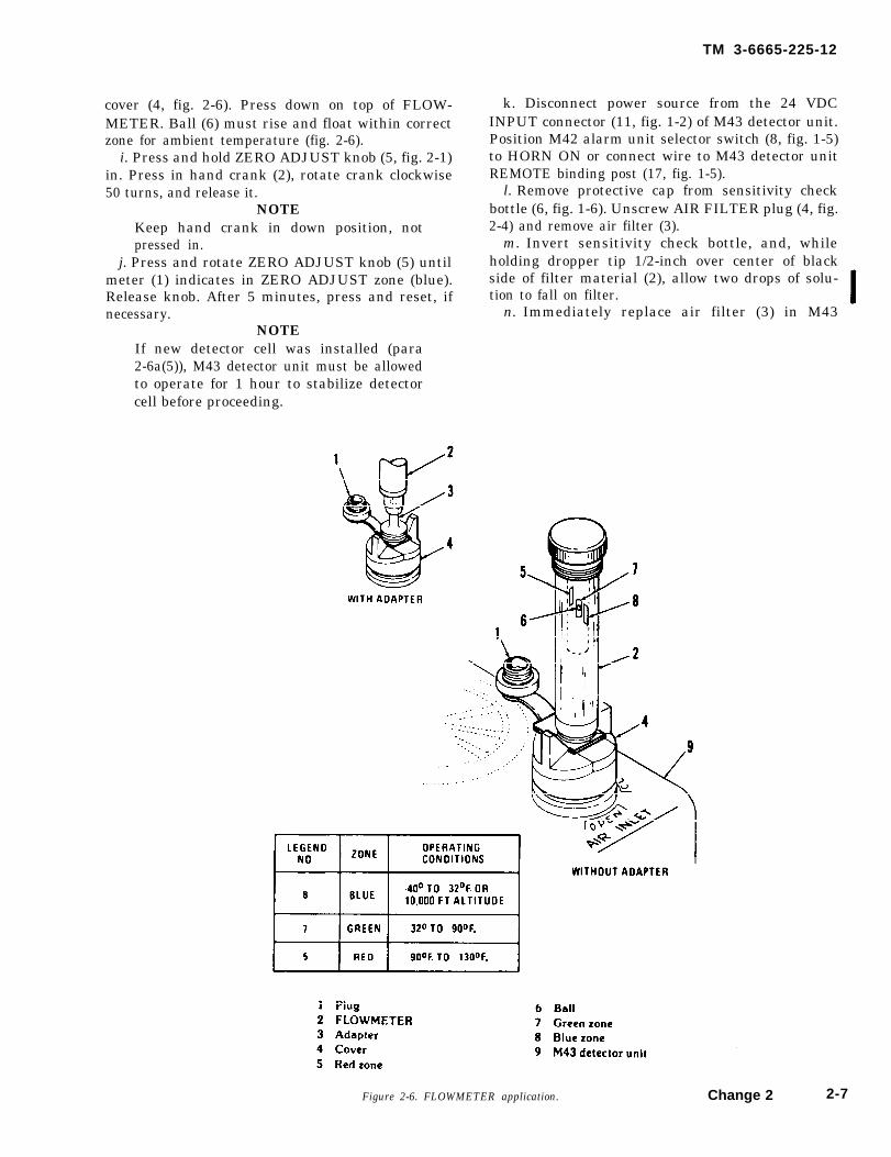
cover (4, fig. 2-6). Press down on top of FLOW-METER. Ball (6) must rise and float within correctzone for ambient temperature (fig. 2-6).
i. Press and hold ZERO ADJUST knob (5, fig. 2-1)in. Press in hand crank (2), rotate crank clockwise50 turns, and release it.
NOTEKeep hand crank in down position, notpressed in.
j. Press and rotate ZERO ADJUST knob (5) untilmeter (1) indicates in ZERO ADJUST zone (blue).Release knob. After 5 minutes, press and reset, ifnecessary.
NOTE
k. Disconnect power source from the 24 VDCINPUT connector (11, fig. 1-2) of M43 detector unit.Position M42 alarm unit selector switch (8, fig. 1-5)to HORN ON or connect wire to M43 detector unitREMOTE binding post (17, fig. 1-5).
l. Remove protective cap from sensitivity checkbottle (6, fig. 1-6). Unscrew AIR FILTER plug (4, fig.2-4) and remove air filter (3).
m. Invert sensitivity check bottle, and, whileholding dropper tip 1/2-inch over center of blackside of filter material (2), allow two drops of solu-tion to fall on filter.
n. Immediately replace air filter (3) in M43
If new detector cell was installed (para2-6a(5)), M43 detector unit must be allowedto operate for 1 hour to stabilize detectorcell before proceeding.
Change 2Figure 2-6. FLOWMETER application. 2-7

TM 3-6665-225-12
detector unit and secure AIR FILTER plug (4). Re-place cap on sensitivity check bottle and return itto M229 refill kit.
o. Connect power source to 24 VDC INPUT con-nector (11, fig. 1-2) of M43 detector unit.
p. Immediately press and hold ZERO ADJUSTknob (5, fig. 2-1) for 5 seconds and release it. Within15 seconds to 5 minutes, M43 detector unit horn (3)must sound, M42 alarm unit loudspeaker (5, fig. 1-5)must sound, and ALARM-RED indicator (3) mustflash.
NOTEIf M43 detector unit horn does not sound,repeat j. through p. above twice, if neces-sary. Use a new filter each time. Then referto table 3-3 for operator’s troubleshootinginformation.
q. Disconnect power source connector from M43detector unit 24 VDC INPUT connector (11, fig. 1-2).
r. Remove AIR FILTER plug (4, fig. 2-4) and dis-card used air filter (3). Open unused air filter pack-age (7, fig. 1-6); discard watertight bag (8). Removeair filter (10) from plastic wrapper (9) and discardplastic wrapper.
S . Insert air filter (3, fig. 2-4) into AIR FIL-TER slot of M43 detector unit (1) with black side offilter material (2) upward. Install and tighten AIRFILTER plug (4).
t. Connect power source to 24 VDC INPUT con-nector (11, fig. 1-2).
u. Press and adjust ZERO ADJUST knob (5, fig.2-1) so that meter (1) indication is within blueZERO ADJUST zone. Then release knob. Repeatafter 5 minutes.
v. Twist FLOWMETER (2, fig. 2-6) clockwise andremove it from AIR INLET assembly cover (4). In-stall FLOWMETER in M43 detector unit handle.
W. Rotate AIR INLET assembly to OPEN position(fig.
x.
2-5, B).CAUTION
To prevent damage by overheating, neveroperate M43 detector unit with AIR INLETassembly in CLOSED position and AIRINLET plug (1, fig. 2-6) installed.Install and secure AIR INLET plug (1).
NOTEThe alarm system is now operational.When in operation, keep the M43 generallyin an upright position. Tilt angles greaterthan 45º may cause improper operation.
2-10. Continuous Use-Checks and ReservicingProcedures
The following prescribes power-source checks andM43 detector unit reservicing procedures that mustbe performed every 12 hours when an alarm system
2-8 Change 2
is operating continuously.a. If M10 power supply and standby battery are
in use, perform following voltage level checks:(1) Check voltage output of M10 power supply
by pressing M43 detector unit HORN VOL-BATTERY TEST knob (6, fig. 2-1). Meter (1) mustindicate 24 minimum. Position M10 power supplypower switch (3, fig. 2-2) to OFF.
(2) Check voltage output of standby battery bypressing M43 detector unit HORN VOL-BATTERYTEST knob (6, fig. 2-1). Meter (1) must indicate 24minimum. Replace discharged battery. Return dis-charged BB501/U battery to organizational main-tenance for recharging. Discard dischargedBA3517/U battery.
b. If BA3517/U battery or BB501/U battery areused as primary power sources, or if alarm systemis installed in vehicle, check power source voltageoutput (a(2) above).
C. Reservice M43 detector unit as follows:(1) Disconnect power source from 24 VDC IN-
PUT connector (11, fig. 1-2).(2) Remove one solution reservoir assembly (5,
fig. 1-6) from drawer (1) of M229 refill kit.(3) Prepare solution (fig. 2-3).(4) Install reservoir assembly (para 2-7c).(5) Rotate AIR INLET assembly to CLOSED
position. Unscrew plug (1, fig. 2-5A).(6) Press ZERO ADJUST knob (5, fig. 2-1), ro-
tate it fully clockwise, and release it.NOTE
Notify personnel within audible range thatalarm system is to be tested.(7) Connect power source connector 24 VDC
INPUT connector (11, fig. 1-2) of M43 detector unit.M43 detector unit horn (2, fig. 1-2) and M42 alarmunit loudspeaker (5, fig. 1-5) must sound.
(8) Position M42 alarm unit selector switch (8,fig. 1-5) to HORN OFF or disconnect one wire fromM43 detector unit REMOTE binding post (17, fig.1-2). Adjust HORN VOL-BATTERY TEST knob (6,fig. 2-1) for desired level.
(9) Press ZERO ADJUST knob (5), rotate itfully counterclockwise, release it. Horn must stopsounding and pump must operate.
(10) Press HORN VOL-BATTERY TEST knob(6). Meter (1) must indicate 24 minimum. Releaseknob.
(11) Remove FLOWMETER (3, fig. 1-3) fromhandle (2). Insert and twist FLOWMETER firmlyclockwise into top of AIR INLET assembly cover (4,fig. 2-6). Press down on top of FLOWMETER. Bail(6) must rise and float within correct zone for am-bient temperature (fig. 2-6).

TM 3-6665-225-12
(12) Press and hold ZERO ADJUST knob (5,fig. 2-1) in. Press in hand crank (2), rotate crankclockwise 50 turns, and release it.
NOTEKeep hand crank in down position, notpressed in.(13) Press and rotate ZERO ADJUST knob un-
til meter (1) indicates in ZERO ADJUST zone (blue).Release knob. After 5 minutes, press and reset, if ne-cessary.
(14) Disconnect power source connector fromM43 detector unit 24 VDC INPUT connector (11,fig. 1-2).
(15) Remove protective cap from sensitivitycheck bottle (6, fig. 1-6). Unscrew AIR FILTER plug(4, fig. 2-4) and remove air filter (3).
(16) Invert sensitivity check bottle and, whileholding dropper tip 1/2 inch over center of blackside of filter material (2), allow two drops of solu-tion to fall on filter.
(17) Immediately replace air filter (3) in M43detector unit and secure AIR FILTER plug (4). Re-place cap on sensitivity check bottle.
(18) Connect power source to 24 VDC INPUTconnector (11), fig 1-2) of M43 detector unit.
(19) Immediately press and hold ZERO AD-JUST KNOB (5, fig. 2-1) for 5 seconds and releaseit. Within 15 seconds to 5 minutes, M43 detectorunit horn (3) must sound.
NOTEIf M43 detector unit horn does not sound,repeat (13) through (19) above twice, ifnecessary. Use a new filter each time. Thenrefer to table 3-3 for operator’s trouble-shooting information.(20) Disconnect power source connector from
M43 detector unit 24 VDC INPUT connector (11,fig. 1-2).
(21) Remove AIR FILTER plug (4, fig. 2-4) anddiscard used air filter (3). Open unused air filterpackage (7, fig. 1-6), discard watertight bag (8).Remove air filter (10) from plastic wrapper (9) anddiscard plastic wrapper.
(22) Insert air filter (3, fig. 2-4) into AIR FIL-TER slot of M43 detector unit (1) with black side offilter material upward. Install and tighten AIRFILTER plug (4).
(23) Position M42 alarm unit selector switch (8,fig. 1-5) to HORN ON or connect wire to M43 de-tector unit REMOTE binding post (17, fig. 1-2).
(24) Connect power source connector to M43detector unit 24 VDC INPUT connector (11, fig. 1-2).
(25) Press and adjust ZERO ADJUST knob (5,fig. 2-1) so that meter (1) indication is within blueZERO ADJUST zone. Then release knob. Repeatafter 5 minutes.
(26) Twist FLOWMETER (2, fig. 2-6) clockwiseand remove it from AIR INLET assembly cover (4).Install FLOWMETER in M43 detector unit handle.
(27) Rotate AIR INLET assembly to OPENposition (fig. 2-5, B).
CAUTIONTo prevent damage by overheating, neveroperate M43 detector unit with AIR IN-LET assembly in CLOSED position andAIR INLET plug (1) installed.(28) Install and secure AIR INLET plug (1), or
if M43 detector unit is mounted on a vehicle, re-move RAINSHIELD assembly (1, fig. 1-3) and in-stall and secure it in cover (4, fig. 2-6).
NOTEThe alarm system is now operational.
2-11. Operational AlertNOTE
The M43 detector unit will signal whenexposed to heavy concentrations of rocketpropellant smoke, screening smoke, signal-ing smoke, engine exhaust, or in the eventof nuclear explosion.
When the alarm system signals the presence ofchemical agents, perform the following:
a. Immediately take protective measures pre-scribed in FM 21-41.
b. Give local alert as prescribed by local stan-ding operating procedures (SOP).
c. Disconnect power source from M43 detectorunit 24 VDC INPUT connector (11, fig. 1-2).
d. Set AIR INLET assembly cover (4, fig. 2-5) toCLOSED position (fig. 2-5, A). Remove RAIN-SHIELD assembly (1, fig. 1-3) from cover, if used.Install electrical connector cover (10, fig. 1-2) on 24VDC INPUT connector (11). Install AIR OUTLETcap (15) on AIR OUTLET port of M43 detector unit.
CAUTIONDo not remove bottom case assembly (9) inpresence of chemical agents. Exposure tochemical agents will render the M43 de-tector unit useless. Chemicals used for de-contamination will damage the interior ofthe M43 detector unit.
Change 2 2 -9

TM 3-6665-225-12
e. If presence of chemical agent has been veri-fied, decontaminate exterior of all components (TM3-220).
2-12. Reactivating Alarm System AfterOperational AlertAfter an all-clear has been sounded, the alarm sys-tem can be reactivated for the remainder of a 12-hour mission at the discretion of the unit comman-der.
NOTEIf the alarm system is to be operational fortwo or more continuous missions, performchecks and reservicing procedures (para2-10) after each 12-hour mission.
a. Remove AIR OUTLET cap (15, fig. 1-2) fromAIR OUTLET port.
b. Remove plug (1, fig. 2-5) from AIR INLETcover (4).
c. Remove FLOWMETER (3, fig. 1-3) from han-dle (2). Insert and twist FLOWMETER firmly clock-wise into top of AIR INLET cover (4, fig. 2-6).
d. Remove electrical connector cover (10, fig. 1-2)from 24 VDC INPUT connector (11).
e. Connect power source connector to 24 VDCINPUT connector (11). Horn (2) must sound. AdjustHORN VOL-BATTERY TEST know (6, fig. 2-1) fordesired level.
f. Press HORN VOL-BATTERY TEST knob (6).Meter (1) must indicate 24 minimum. Release knob.
g. Press ZERO ADJUST Knob (5), rotate it fullycounterclockwise, and release it. Horn must stopsounding and pump assembly must operate.
h. Press down on top of FLOWMETER. Ballmust float within correct zone for ambient temper-ature (fig. 2-6).
i. Press and rotate ZERO ADJUST knob (5) untilmeter (1) indicates in ZERO ADJUST zone (blue).Release ZERO ADJUST knob (5, fig. 2-1). After 5minutes, press and reset, if necessary.
j. If meter (1) does not indicate in ZERO ADJUSTzone (blue), press and hold ZERO ADJUST knob (5)in. Press in hand crank (2), rotate crank clockwise25 turns and release it. Repeat i above.
k. Rotate AIR INLET assembly to OPEN position(fig. 2-5, B).
l. Twist FLOWMETER (2, fig. 2-6) clockwise and
remove it from AIR INLET assembly cover (4). In-stall FLOWMETER in M43 detector unit handle. In-stall plug (1, fig. 2-5) in cover (4) or if vehicle-mounted, install RAINSHIELD assembly (1, fig. 1-3)in cover.
2-13. Shutdown Proceduresa. Shutdown For More Than 72 Hours. If alarm
system is to be shutdown for more than 72 hours,return M43 detector unit and M42 alarm unit toorganizational maintenance for administrative stor-age (para 5-3 and 5-4) or shipment (para 5-1 and5-2).
b. Shutdown For 72 Hours or Less. If alarm sys-tem is to be shutdown for 72 hours or less and re-used within 72 hours, perform following procedures:
(1) If M10 power supply is in use, set 115V/OFF/220V power switch (3, fig. 2-2) to OFF.
(2) Press HORN VOL-BATTERY TEST switch(6, fig. 2-1) on M43 detector unit and note indicationof meter (l). If meter indicates less than 24, discardBA3517/U battery or forward BB501/U battery toorganizational maintenance for recharging.
(3) Disconnect power source from 24 VDC IN-PUT connector (11, fig. 1-2).
(4) Install electrical connector cover (10) on 24VDC INPUT connector (11).
(5) Press in M43 detector unit REMOTE bin-ding post (17), remove telephone cable connections,and release binding posts.
(6) Release four clamping catches (12) frombottom catches (13). Remove the detector unit as-sembly (6) from the bottom case assembly (9).
(7) Remove reservoir assembly (12, fig. 1-3).Discard solution in accordance with standing oper-ating procedures. Install empty reservoir assembly todectector unit assembly.
(8) Insure that seal (1, fig. 1-4) is correctly sea-ted in groove around the top of bottom case assem-bly (9, fig. 1-2); then fasten four clamping catches(12).
(9) Set AIR INLET assembly to CLOSED PO-SITION (fig. 2-5, A).
(10) Pull up hand crank (2, fig. 2-1) to storageposition.
(11) Install AIR OUTLET cap (15, fig. 1-2) onAIR OUTLET port.
2-10 Change 2

TM 3-6665-225-12
Section III. OPERATION UNDER UNUSUAL CONDITIONS
2-14. General
This section contains instructions for operating theequipment in tropical environments, in tempera-tures below 40ºF., in blowing sand or dust, and inraining, sleeting, or snowing environments.
NOTEIn tropical environments, inspect the M42alarm unit batteries every 15 days for elec-trolyte leakage. Replace defective batteriesimmediately. Replace batteries installed inM42 alarm units every 30 days as a mini-mum.
NOTEIf the alarm system is to be operational fortwo or more continuous missions, performchecks and reservicing procedures (para 2-10) after each 12-hour mission.
2-15. Operation in Temperatures Below40°F.
a. Perform preoperational procedures of para-graph 2-6.
b. Remove one air filter package (7, fig. 1-6), onesensitivity check bottle (6), and one reservoir as-sembly (5) from M229 refill kit. Thaw liquid in sen-sitivity check bottle and in reservoir assembly if fro-zen.
c. Install air filter (para 2-7d).NOTE
When operating between 40°F. and 20°F.,use either BA3517/U battery (7, fig. 1-1) orBB501/U battery (9, fig. 2-7) and M168 ca-ble (5) as prime power source or standbybattery for M10 power supply. When oper-ating below 20°F., use only BB501/U bat-tery and M168 cable as primary powersource or standby battery for M10 powersupply. Use table 1-2 as a guide for deter-mining maximum number of missions be-fore exchanging BA3517/U battery for afresh battery or exchanging BB501/Ubattery for a freshly charged battery.
d. Install alarm system in accordance with ap-propriate instructions in paragraphs 3-1 through3-4.
NOTEDo not connect power to M43 detector unit24 VDC INPUT connector until instructedto do so.
e. Remove AIR OUTLET cap (15, fig. 1-2) fromAIR OUTLET port.
f. Remove electrical connector cover (10) from 24VDC INPUT connector (11).
g. Check that AIR INLET assembly is in
CLOSED position (fig. 2-5, A). Unscrew plug (1).h. Press ZERO ADJUST knob (5, fig. 2-1), rotate
it fully clockwise and release it. Rotate HORN VOL-BATTERY TEST knob fully clockwise.
i. Notify personnel within audible range thatalarm system is to be tested.
NOTEIf any startup tests fail, refer to table 3-3for operator’s troubleshooting information.
j. Startup M43 detector unit as follows:NOTE
In temperature below 40°F., M43 detectorunit may require warmup to start pumpassembly motor. Lower temperatures re-quire longer warmup, but no longer than50 minutes.(1) Connect power source connector to 24 VDC
INPUT connector (11, fig. 1-2). If M10 power supplyis used, set power switch (3, fig. 2-2) to correct inputvoltage position.
(2) If M43 detector unit horn (2, fig. 1-2) soundsor pump assembly motor runs, proceed to (4) below.
(3) If horn does not sound or pump assemblydoes not run, M43 detector unit is in warmup mode.Do not proceed until M43 detector unit horn soundsor pump assembly motor runs. Then proceed to (4)below.
(4) Position M42 alarm unit selector switch (8,fig. 1-5) to HORN OFF, or disconnect one wirefrom M43 detector unit REMOTE binding post (17,fig. 1-2). Horn must be off. Disconnect power sourcefrom 24 VDC INPUT connector (11).
(5) Prepare solution as described in figure 2-3.NOTE
To prevent the M43 detector unit fromcooling off, keep bottom case assemblyseparated from detector assembly for asshort a time as possible.(6) Release four clamping catches (12, fig. 1-2)
from bottom catches (13) and remove the detectorassembly (6) from the bottom case assembly (9).
WARNINGSolution in the reservoir assembly is caus-tic. Avoid contact with eyes and mouth.Flush from skin with water.
CAUTIONKeep weight assembly free from dirt afterremoving the reservoir assembly.(7) Hold the detector assembly upright by its
handle (2, fig. 1-3) and unscrew the reservoir as-sembly (12). Allow the weight assembly to hangdown. Discard used reservoir assembly in accor-dance with standing operating procedures.
(8) Remove and discard cap from the pre-
Change 2 2-11

TM 3-6665-225-12
12345
M43 detector unit 6 Cap24 VDC INPUT receptacle 7 ConnectorConnector 8 CapCap 9 BB501/U batteryM168 cableFigure 2-7. M43 detector unit employing a BB501/U battery and M168 cable.
pared solution reservoir assembly.(9) Center new reservoir assembly under weight
assembly and screw reservoir assembly into moun-ting hole in detector assembly. Insure tight seal byturning reservoir assembly D-ring clockwise.
(10) Check that seal (1, fig. 1-4) is correctlyseated in groove around top of bottom case assem-bly. Assemble detector unit assembly (6, fig. 1-2) tobottom case assembly (9) and secure clampingcatches (12).
NOTEIf M43 detector unit is to be backpacked,position bottom case assembly (9, fig. 1-2)so that instruction plate (3, fig. 1-4) is onthe side opposite the 24 VDC INPUT con-nector (11, fig. 1-2).(11) Connect power source connector to 24
VDC INPUT connector (11, fig. 1-2). M43 detectorunit horn (2, fig. 1-2) will sound in approximately15 minutes.
(12) When horn sounds, press the ZERO AD-
2-12 Change 2
JUST knob (5, fig. 2-1), rotate it fully counterclock-wise, and release it.
(13) Press the HORN VOL-BATTERY TESTknob (6) and check that the meter (1) indicates 24minimum.
(14) If an M10 power supply is used, set thepower switch (3, fig. 2-2) to OFF. Press the HORNVOL-BATTERY TEST Knob (6, fig. 2-1) and checkthat the meter (1) indicates 24 minimum (standbybattery voltage). Set the power switch (3, fig. 2-2) tothe correct voltage position. Turn the annunciator(8) clockwise, then fully counterclockwise.
(15) Unscrew RAINSHIELD assembly (1, fig.1-3) from handle (2). Pull rainshield (13) fromadapter (14). Screw rainshield (13) into handle. Un-screw plug (1, fig. 2-6) from AIR INLET assemblycover (4). Screw adapter (2, fig. 2-8) into cover (3).
(16) Remove FLOWMETER (3, fig. 1-3) fromhandle (2). Insert and twist FLOWMETER firmlyclockwise into top of AIR INLET assembly cover (4,fig. 2-6). Press down on top of FLOWMETER. If

TM 3-6665-225-12
flowmeter ball (6) is in the blue zone (8), proceed to(19) below. If flowmeter ball (6) indicates no airflow,proceed to (17) below. If flowmeter ball (6) indicateslow airflow, proceed to (18) below.
NOTEAdjust HORN VOL-BATTERY TEST knob(6, fig. 2-1) for low volume. Position M42alarm unit selector switch (8, fig. 1-5) toHORN OFF or disconnect one wire fromM43 detector unit REMOTE binding post(17, fig. 1-2).(17) If no airflow is indicated, press ZERO
ADJUST knob (5, fig. 2-1), rotate it fully clockwise,and release it. Horn must sound. Check airflowevery 2 minutes by pressing ZERO ADJUST knob(5) and observing FLOWMETER (2, fig. 2-6). Whenbail (6) rises in FLOWMETER, indicating low air-flow, press ZERO ADJUST knob (5, fig. 2-1) androtate it fully counterclockwise and proceed to (18)below.
(18) If low airflow is indicated, let pump as-sembly operate until correct airflow (blue zone) isindicated (less than 30 minutes). Then proceed to
(19) below.(19) Press in hand crank (2, fig. 2-1) and release
it.NOTE
Keep hand crank in the down position, notpressed in.(20) After 10 minutes of operation at normal
airflow, press and rotate ZERO ADJUST knob (5)until meter (1) indicates in ZERO ADJUST zone(blue). Repeat at 10-minute intervals until meterreading is stable.
(21) Disconnect power source from the 24 VDCINPUT connector (11, fig. 1-2) of M43 detector unit.Position M42 alarm unit selector switch (8, fig. 1-5)to HORN ON or reconnect wire to M43 detectorunit REMOTE binding post (17, fig. 1-2).
(22) Remove protective cap from the sensitivitycheck bottle (6, fig. 1-6). Unscrew AIR FILTER plug(4, fig. 2-4) and remove air filter (3).
(23) Invert sensitivity check bottle and, whileholding dropper tip 1/2 inch over center of blackside of filter material (2), allow two drops of
Figure 2-8. RAINSHIELD assembly application.
horn (3) must sound, M42 alarm unit loudspeakersolution to fall on the filter.(24) Immediately replace air filter (3) in M43
detector unit and secure AIR FILTER plug (4). Re-place cap on sensitivity check bottle.
(25) Connect power source to 24 VDC INPUTconnector (11, fig. 1-2) of M43 detector unit.
(26) Immediately press and hold ZERO AD-JUST knob (5, fig. 2-1) for 5 seconds and release it.Within 15 seconds to 5 minutes, M43 detector unit
(5, fig. 1-5) must sound, and ALARM-RED indicator(3) must flash.
NOTEIf M43 detector unit horn soundsthan 15 seconds, disconnect powerand return unit to organizationalnance through your supervisor.
Change 2
in lesssourcemainte-
2-13

TM 3-6665-225-12
NOTEIf M43 detector unit horn does not sound,disconnect power source from 24 VDCINPUT connector, and repeat (22) through(26) above twice, if necessary. Use a newfilter each time. Then refer to table 3-3 foroperator’s troubleshooting information.(27) Disconnect power source connector from
M43 detector unit 24 VDC INPUT connector (11,fig. 1-2).
(28) Immediately continue operation by per-forming the procedures of paragraph 2-9r throughx.
NOTEThe alarm system is now operational.
2-16. Operation in Rain or SleetNOTE
After separating M43 detector unit bottomcase assembly and detector assembly, posi-tion bottom case assembly with its bottomup to keep inside as dry as possible. Alsoshield components mounted under detectorassembly with the body as much as possi-ble.
a. Perform preoperational procedures of para-graph 2-6.
b. Remove RAINSHIELD assembly (1, fig. 1-3)from handle (2).
c. Unscrew AIR INLET assembly plug (1, fig. 2-8).d. Screw RAINSHIELD assembly (1, fig. 1-3) into
AIR INLET assembly cover (3, fig. 2-8).NOTE
When using FLOWMETER, pull rainshield(5) away from adapter (2) and installFLOWMETER (2, fig. 2-6) over adapter (2,fig. 2-8). Screw rainshield (13) into handle(2). To remove FLOWMETER turn itclockwise and pull from adapter. Removerainshield from handle and install overadapter.
e. If air temperature is above 40°F., perform pro-cedures of paragraphs 2-7 through 2-9.
f. If air temperature is 40°F. or below, proceed toparagraph 2-15b.
2-17. Operation in Snowa. Perform preoperational procedures of para-
graph 2-6.b. Unscrew RAINSHIELD assembly (1, fig. 1-3)
from handle (2).
c. Pull rainshield (13) from adapter (14). Screwrainshield (13) into handle (2).
d. Unscrew AIR INLET assembly plug (1, fig. 2-8).e. Screw adapter (14, fig. 1-3) into AIR INLET
assembly cover (3, fig. 2-8).
f.
NOTEWhen using FLOWMETER (2, fig. 2-6), in-stall FLOWMETER over adapter (2, fig.2-8). When removing FLOWMETER, turnit clockwise and pull from adapter.If air temperature is 40°F. or above, perform
procedures of paragraphs 2-7 through 2-9.g. If air temperature is below 40°F. proceed to
paragraph 2-15b.
2-18. Operation in Blowing Sand or DustCAUTION
Do not remove bottom case assembly(9, fig. 1-2) or air filter (3, fig. 2-4) inpresence of blowing sand or dust. Per-form preoperational procedures (para 2-6)in a sheltered area such as inside a build-ing, inside of a vehicle, or under a lean-to.Contamination of the components withinthe M43 detector unit with sand or dustwill render it useless.
a. When bottom case assembly is removed, in-spect for presence of sand or dust. Carefully removeany foreign material being careful not to damagecomponents.
b. Before reassembling bottom case assembly (9,fig. 1-2) and detector unit assembly (6), wipe seal (1,fig. 1-4) and mating groove in detector assembly toinsure watertight and airtight seal when they areassembled.
c. Replace air filter (3, fig. 2-4) at intervals pre-scribed in table 2-1 using the following procedure.
(1) Disconnect power source from 24 VDC IN-PUT connector.
(2) Replace air filter with a new one. Make surethe Air Filter plug is tightly installed.
(3) Reconnect power source to 24 VDC INPUTconnector.
(4) Check airflow (para 2-9h).d. If air temperature is 40°F. or above, operation
is the same as under usual conditions, starting withpreoperation procedures (para 2-6).
e. If air temperature is below 40°F., operation isas prescribed in paragraph 2-15.
2-14 Change 2

TM 3-6665-225-12
Table 2-1. Air Filter Replacement Interval
Section IV. DAILY LOG FOR M43 DETECTOR UNIT AND PUMP ASSEMBLY
2-19. M43 Detector UnitA modified DA Form 2408-1 (fig. 2-9), Equip-ment Daily or Monthly Log, is used to record dailyand accumulated operating hours for the M43 de-tector unit (fig. 1-2). It also provides a means of de-termining when a pump assembly (7, fig. 1-3) mustbe removed and sent to direct support for scheduledmaintenance (tubing replacement every 1440hours).
a. Modification of DA Form 2408-1.(1) Block 2. Line out “REGISTRATION OR.”(2) Block 3. Line out “OR LUBRICATION
DUE.”(3) Block 4, Column b. Line out “READING”
and add “DAILY.”(4) Block 4, Column c. Line out “READING
MILES” and add “TOTAL HOURS.”(5) Block 4, Column i. Enter “PUMP ASSEM-
BLY” in first column.b. Use of Modified DA Form 2408-1.
(1) Block 1. Enter “DETECTOR UNIT, CHEM-ICAL AGENT AUTOMATIC ALARM: PORTA-BLE, M43.”
(2) Block 2. Enter serial number of the M43detector unit.
(3) Block 3a. Not applicable.(4) Block 3b. Enter the hours when the next
pump assembly replacement is due. The hours aredetermined in the following manner:
(a) When putting a new M43 detector unitinto service (no prior operating hours on M43 orpump assembly), enter 1440 hours in 3b.
(b) When changing a pump assembly in aused M43 detector unit and the pump assembly isused, determine the number of pump operating
hours since last tubing replacement (from DA Form2408-1 accompanying pump), subtract these hoursfrom 1440, and add result to total M43 hourslogged. Enter this number in 3b. Example: TotalM43 detector hours on log are 1437. Pump assemblyto be installed has been operated 400 hours.
1440 - 400 = 1040 hrs.1437 + 1040 = 2477 hrs (enter in 3b).
(c) When changing a pump assembly in aused M43 detector unit and the pump assembly isnew, add 1440 hours to the total M43 hours loggedand enter result in 3b. Example: Total M43 detectorhours on log are 1474. Pump assembly is replacedwith a new pump.
1474 + 1440 = 2914 hrs (enter in 3b).(d) When pump assembly operating hours
since last tubing replacement are not known, sendpump to direct support for tubing replacement.
(5) Block 3c. Not applicable.(6) Block 4. Enter a check in the daily block.(7) Block 4, column a. Enter date M43 is/was
operating.(8) Block 4, Column b. Enter daily operating
hours.(9) Block 4, Column c. Enter cumulative hours
operated.(10) Block 4, columns d and e. Not applicable.(11) Block 4, Column f. Enter a check in the
“IS EQUIPMENT OPERATIONAL” column if theequipment is operational. If equipment is not oper-ational, leave the column blank and enter an “x” inthe “EQUIPMENT FAULT” column.
(12) Block 4, Column g.making entries in columns a
(13) Block 4, Column h.
Signature of individualthrough f.Not applicable.
Change 2 2-15

TM 3-6665-225-12
(14) Block 4, Column i. Enter "CH" when pump the pump assembly since the last 1440 hour serviceassembly is changed. Specify reason for change in in the “M” column. Do not use the "SUPPORT“REMARKS” block. MAINT" columns. Revise block 3b.
(15) Block 4, Column j. Under “ORG MAINT,” (16) Block 4, Column k. Signature of individualenter the serial number of the pump assembly in use making entries in columns i and j.in the “S” column. Enter the operational hours of
Figure 2-9. Sample DA Form 2408-1 modified for use with M43 detector unit.
2-16

TM 3-6665-225-12
2-20. Pump AssemblyA modified DA Form 2408-1 (fig. 2-10), EquipmentDaily or Monthly Log, is used to record the numberof pump operating hours since last tubing replace-ment when a pump assembly is removed from anM43 detector unit for maintenance. This form iskept with the pump assembly until it is reinstalledin an M43 detector unit and the action recorded inthe M43 detector unit log. The pump assembly logis then discarded.
a. Modification of DA Form 2408-1.(1) Block 2. Line out “REGISTRATION OR.”(2) Block 4. Line out “DAILY” and “MON-
THLY” and add “SCHED. MAINT.”(3) Block 4, Column c. Line out “READING
MILES” and add an asterisk (*) and “HOURS.” Useanother asterisk (*) to explain at bottom of formthat hours entered are “operating hours since lasttubing replacement.”
b. Use of Modified DA Form 2408-1.(1) Block 1. Enter “PUMP ASSEMBLY, M43
DET.”(2) Block 2. Enter pump serial number.(3) Block 3. Not applicable.
(4) Block 4, Column a. Enter date of entry.(5) Block 4, Column b. Not applicable.(6) Block 4, Column c. Enter pump assembly
operating hours since last tubing replacement fromM43 detector unit daily log. Example: Pump as-sembly Serial No. 172 is removed from M43 SerialNo. 0012 for maintenance. M43 total hours at timeof removal is 1507 hours (see fig. 2-9); pump opera-ting hours since last tubing replacement is 33 hours(1507-1474). Entry in column 4c of pump DA Form2408-1 is 33 (see fig. 2-10).
(7) Block 4, Columns d through j. Not applica-ble.
(8) Block 4, Column k. Signature of individualmaking entries.
(9) Add a note to form stating “KEEP THISFORM WITH PUMP ASSEMBLY UNTIL PUMP ISINSTALLED INTO AN M43 DETECTOR UNITAND THE ACTION RECORDED IN M43 DETEC-TOR UNIT LOG.” See figure 2-10.
(10) Form is now completed. Attach form topump. Fold, wrap around pump, and secure withrubber band, item 6, table 1-3.
Change 2 2-17

TM 3-6665-225-12
Figure 2-10. Sample DA Form 2408-1 modified for use with pump assembly.
2-18 Change 2

TM 3-6665-225-12
CHAPTER 3
OPERATOR’S MAINTENANCE INSTRUCTIONS
Section I. INSTALLATION
3–1. GeneralThe operator is authorized to install the M43detector unit, M42 alarm unit, M229 refill kit,M10 power supply, and batteries. Prior to install-ing an item, the operator must inspect not onlythe item, but the equipment in which it is to beinstalled.
3–2. Fixed Emplacement InstallationOperator’s installation procedures at fixedemplacement entail connecting the M43 detectorunit to a power source and to one or more M42alarm units.
a. M43 Detector Unit Employing BA3517/UBattery. The number of missions that aBA3517/U battery can be used is determined bythe air temperature in which it is required tooperate. Refer to table 1-2 to determine the maxi-mum number of allowable 12-hour missions for aBA3517/U battery in a specific temperature.
(1) Perform applicable preoperation pro-cedures (para 2-6) and pre-startup procedures(para 2-7).
(2) Attach BA3517/U battery (2, fig. 3-1) tobottom of M43 detector unit (1) by inserting catch(5) into slot in metal strap (4).
(3) Insert clamping catch (3, fig. 1-7) ontoother catch striker on the opposite side of M43detector unit and lock.
(4) Perform startup and operation pro-cedures (para 2-9).
b. M43 Detector Unit Employing M253Winterization Kit. An M253 winterization kit,consisting of two BB501/U batteries and oneM168 cable, is used to supply battery power whenthe M43 detector unit is used in temperatures be-tween 20°F. and -40°F. Refer to table 1-2 todetermine the maximum number of allowablecontinuous 12-hour missions for a BB501/U bat-tery before recharging.
(1) Perform preoperation procedures (para2-6) and pre-startup procedures (para 2-7).
(2) Turn protective cap (4, fig. 2-7) counter-clockwise and pull it from connector (3) of M168cable (5).
(3) Pull protective cap (6) from connector (7)of M168 cable.
(4) Remove protective cap (8) of BB501/Ubattery receptacle.
(5) Plug connector (7) of M168 cable intoreceptacle on top of BB501/U battery (9) aftersqueezing two spring clips on sides of connector(7).
(6) With keyways alined, firmly pushconnector (7) onto battery receptacle and releasespring clips to lock connector in place.
(7) Perform setup and operation procedures(para 2-9).
c. M43 Detector Unit Employing M10 PowerSupply. The fixed emplacement arrangement (fig.3-2) of the alarm system uses an M10 powersupply (1) as a power source. The M10 powersupply requires an input voltage of 115 or 220volts at a frequency of 50, 60, or 400 hertz. Astandby battery (either the BA3517/U or theBB501/U employed with the M43 detector unit) isconnected to the M10 power supply to auto-matically provide power to the M43 detector unitin the event of a power failure. If the M10 powersupply output voltage decreases to less than 18volts, a relay in the M10 power supply connectsstandby battery power to the M43 detector unit.
(1) Be sure that applicable preoperation pro-cedures (para 2-6) and pre-startup procedures(para 2-7) have been performed.
NOTEMake sure that M10 power supplypower switch (3, fig. 2-2) is in OFFposition.(2) Connect DETECTOR POWER cable
(W2) (3, fig. 3-2) to M43 detector unit 24 VDCINPUT connector (2).
(3) Connect STANDBY BATTERY cable (4)to BA3517/U battery or to M168 cable which isconnected to BB501/U battery.
NOTERefer to table 1-2 to determine whichbattery is to be used as power source.
(4) Place M10 power supply power switch (3,fig. 2-2) to proper input voltage position.
(5) Rotate annunciator (8) fully clockwiseand then fully counterclockwise.
(6) Press M43 detector unit HORN VOL-
234-774 O - 89 - 2
3-1

TM 3-6665-225-12
Figure 3-1. M43 detector unit employing a BA3517/U battery.
BATTERY TEST knob (6, fig. 2-1) to check that minimum as indicated on M 43 detector unit meteroutput voltage of M10 power supply is 24 volts (1).minimum as indicated on M43 detector unit meter (9) Place M10 power supply power switch (3,(1). fig. 2-2) to the proper input voltage position.
(7) Position M10 power supply power switch (10) Rotate annunciator (8) fully clockwise(3, fig. 2-2) to OFF. and fully counterclockwise to reset it.
(8) Press M43 detector unit HORN VOL- (11) Perform startup and operation proce-BATTERY TEST knob (6, fig. 2-1) to check that dures (2-9).output voltage of standby battery is 24 volts
3-2

TM 3-6665–225-12
Figure 3-2. M43 detector unit employing an M10 power supply.
d. M43 Detector Unit Employing M42 AlarmUnit(s). A fixed emplacement arrangement ofone M43 detector unit employing one to five M42alarm units (fig. 3-3) permits the M43 detectorunit to be remoted from an upwind location.
NOTEDo not connect more than one M43detector unit in a system.
Two-wire telephone cable is used to connect eachM42 alarm unit to an M43 detector unit. The M42alarm units are placed at or close to monitoringpositions.The M43 detector unit and its power source areplaced up to 400 meters upwind. When more thanone M42 alarm unit is connected to an M43 detec-tor unit, the warning can be monitored at severalpositions.
(1) Perform applicable preoperation pro-cedures (para 2-6) and pre-startup procedures(para 2-7).
(2) Using figure 3-3 as a guide for variousmethods of connecting M42 alarm units to an M43
detector unit, position the M42 alarm units withrelation to M43 detector unit so that telephonecable (5) lengths will not exceed distances speci-fied.
(3) String telephone cabledetector unit (2) and each M42allowing approximately 1 foot ofeach wire.
(4) Tie each telephone cable
between M43alarm unit (1)slack at end of
wire to D-ring(7) on its associated M42 alarm unit about 9inches from end of each telephone cable wire.
(5) Strip about one-half-inch of insulationfrom end of- each wire.
(6) Without regard towire to each binding post (6)
(7) Repeat (4) throughM42 alarm unit used.
polarity, connect aon M42 alarm unit.(6) above for each
(8) Strip about one-half-inch of insulationfrom the ends of the telephone cable wires to beconnected to the M43 detector unit.
(9) Tie each wire to loop (4) on M43 detectorunit about 9 inches from end of telephone cable.
3-3

TM 3-6665-225-12
Figure 3-3. M43 detector unit employing M42 alarm unit(s).
3-4

TM 3-6665-225-12
(10) Press in one binding post (3) of M43detector unit and, disregarding polarity, insertone wire of each telephone cable into binding postslot. Release binding post.
(11 ) Repeat (10) above for other binding postand remaining wires.
(12) Perform startup and operation proce-dures (para 2-9).
3-3. Handcarry and Backpack Systemsa. Handy carrying the M43 Detector Unit. T’he
M43 detector unit when handcarried on an opera-tional mission uses a BA3517/U battery for apower source. The BA3517/U battery is securedto the M43 detector unit allowing both units to betransported by the handle of the M43 detectorunit. The M42 alarm unit supplied with the hand-carry configuration permits the system to be usedas a fixed emplacement installation with oneremotely-located M42 alarm unit.
(1) Perform procedures of paragraph3-2a (1) through (3).
(2) If M42 alarm unit is to be used, performprocedures of paragraph 3-2 d (3) through (6) and(8) through (10).
(3) Perform startup and operation proce-dures (para 2-9).
b. Backpacking the M43 Detector Unit. TheM43 detector when operated in the backpackconfiguration uses a BA3517/U battery for apower source. The M43 detector unit andBA3517/U battery are secured to a rucksack witha cargo shelf. The M42 alarm unit supplied withthe backpack configuration permits the system tobe used as a fixed emplacement installation withone remote-located M42 alarm unit.
(1) Perform applicable preoperation pro-cedures (para 2-6) and pre-startup procedure(para 2-7).
(2) Position cargo shelf (4, fig. 3-4) on therucksack (2).
(3) Pass short web strap (1) around top andmiddle bars of rucksack so that strap is centeredbetween right and left sides of rucksack. Thebuckle of short web strap must be on load side ofrucksack and not more than 4 inches from middlebar. Insert plain end of short web strap throughbuckle. Tighten short web strap as taut as possi-ble.
(4) Tie one end of a long web strap (3) toright end of middle bar of rucksack using a non-slip knot.
(5) Tie one end of other long web strap to leftend of middle bar of rucksack using a non-slipknot.
(6) Pass free ends of long web straps throughadjacent outer slots of cargo shelf (4).
(7) Pull cargo shelf into horizontal position.(8) Perform procedures of para 2-9 a through
q.(9) Place rucksack in an upright position.(10) Position M43 detector unit (1, fig. 3-5)
with attached BA3517/U battery (2) on cargoshelf (3) so that AIR FILTER plug (4, fig. 2-4) isfacing away from frame of rucksack (5, fig. 3-5).
CAUTIONDo not block AIR OUTLET.(11) Tie long web strap (4) to right end of
middle bar of rucksack (5). Pass strap across M43detector unit and attached battery. Turn strapfastener loop (6) upward on left side of M43detector unit. Insert long web strap through loop.Pull it until tight.
(12) Pass free end of long web strap aroundtop bar, through slot, and pull it tight. Tie freeend in overhand knot while maintaining tension.
CAUTIONDo not block AIR OUTLET.(13) Pass long web strap (4) which is tied to
left end of middle bar of rucksack across M43detector unit and battery. Insert this long webstrap through strap fastener loop (6) on right sideof M43 detector unit. Keep the long web strap flatand pull it downward until tight. Then pass itsfree end around itself and pull it tight.
(14) Tighten straps to insure that M43detector unit and BA3517/U battery are securelyfastened to rucksack.
(15) Perform the procedures of paragraph2-9 r through x.
3-4. Vehicular System InstallationsVehicular system installations provide accom-modations for an M43 detector unit, and M42alarm unit, and a BA3517/U battery. Primarypower to operate the equipment is supplied by thevehicle’s electrical system. The BA3517/Ubattery provides power when the M43 detectorunit is removed from the vehicle and handcarried.
a. General.(1) The M11 alarm system is installed on a
one-quarter-ton utility truck (fig. 3-6). The M43detector unit is installed and connected to a highprofile mount on the right-front fender of thevehicle. The M42 alarm unit is installed on thedash panel.
(2) The M12 alarm system is installed on athree-quarter-ton truck (fig. 3-7). The M43detector unit is installed and connected to a highprofile mount on the right-front fender of thevehicle. The M42 alarm unit is installed on theright scuff plate in the cab, and a drawer of refillkit components is secured to the upright below
3-5

TM 3-6665-225-12
Figure 3-4. Preparing rucksack for backpacking.
the passenger’s seat cushion.(3) The M13 alarm system is installed on a 2
1/2-ton truck (fig. 3-8). The M43 detector unit isinstalled and connected to a high profile mount onthe rear of the left-front fender. The M42 alarmunit is installed on the cab wall in back of thecompanion seat.
(4) The M14 alarm system is installed on afull-tracked personnel carrier and recovery vehicle(fig. 3-9). The M43 detector unit is installed andconnected to a low profile mount on the hull rightnose plate. The M42 alarm unit and BA3517/Ubattery are mounted on a common bracketsecured to the right rear corner of the hull topplate. Refill kit components are secured in abracket mounted on the battery box on the rightsponson.
(5) The M15 alarm system is installed in anarmored command and reconnaissance vehicle(fig. 3-10). The M43 detector unit is installed and
3-6
connected to a low profile mount on the right frontslope panel. The M42 alarm unit is installed onthe left front slope plate inside of the vehicleunder the left periscope. Refill kit components aresecured to the right sponson.
b. Installing an M43 Detector Unit and aBA3517/U Battery in a High Profile Mount (Partof M228 Mounting Kit).
(1) Perform preoperation procedures (para2-6a) and pre-startup procedures (para 2-7).
(2) Connect BA3517/U battery to the M43detector unit as described in paragraph 3-2a(1)through (3).
(3) Loosen two wingnuts (1, fig. 3-11) byturning them counterclockwise.
(4) Pivot swing clamp (2) forward and down.(5) Insure that shelf is secured in vertical
position by two spring tension clips.(6) Position M43 detector unit and attached
BA3517/U battery on high profile mount as

TM 3-6665-225-12
Figure 3-5. M43 detector unit and BA3517/U battery installed on a rucksack.
shown in figure 3-11. (8) Disconnect cable assembly connector (5)(7) Rotate swing clamp (2) until it is from dummy connector (4) and connect battery
positioned on top edge of M43 detector unit front cable assembly (3) to dummy receptacle (4).panel. Tighten wingnuts (1). (9) Install M42 alarm unit in vehicle (d, e, or
NOTE f below).Do not connect cable assembly con- (10) Perform startup and operationnector (5) to 24 VDC INPUT connector dures (para 2-9) to place equipment into(6) until so instructed. tion.
proce-opera-
3-7

TM 3-6665-225-12
Figure 3-6. M11 alarm system installed in a one-quarter-ton utility truck.
3-8
Figure 3-7. M12 alarm system installed in a three-quarter-ton truck.

TM 3-6665–225–12
Figure 3-8. M13 alarm system installed in a 2 1/2-ton truck.
Figure 3-9. M14 alarm system installed in a full-tracked personnel carrier and recovery vehicle.
3-9
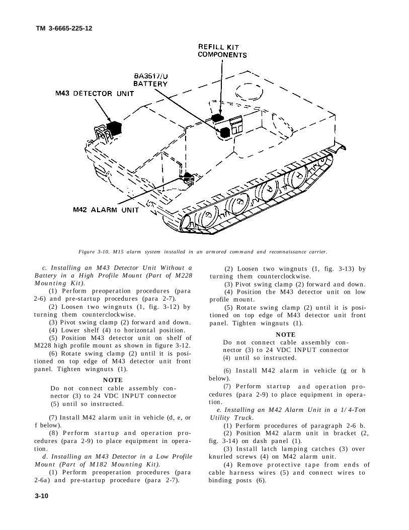
TM 3-6665-225-12
Figure 3-10. M15 alarm system installed in an armored command and reconnaissance carrier.
c. Installing an M43 Detector Unit Without aBattery in a High Profile Mount (Part of M228Mounting Kit).
(1) Perform preoperation procedures (para2-6) and pre-startup procedures (para 2-7).
(2) Loosen two wingnuts (1, fig. 3-12) byturning them counterclockwise.
(3) Pivot swing clamp (2) forward and down.(4) Lower shelf (4) to horizontal position.(5) Position M43 detector unit on shelf of
M228 high profile mount as shown in figure 3-12.(6) Rotate swing clamp (2) until it is posi-
tioned on top edge of M43 detector unit frontpanel. Tighten wingnuts (1).
NOTEDo not connect cable assembly con-nector (3) to 24 VDC INPUT connector(5) until so instructed.
(7) Install M42 alarm unit in vehicle (d, e, orf below).
(8) Perform startup and operation pro-cedures (para 2-9) to place equipment in opera-tion.
d. Installing an M43 Detector in a Low ProfileMount (Part of M182 Mounting Kit).
(1) Perform preoperation procedures (para2-6a) and pre-startup procedure (para 2-7).
(2) Loosen two wingnuts (1, fig. 3-13) byturning them counterclockwise.
(3) Pivot swing clamp (2) forward and down.(4) Position the M43 detector unit on low
profile mount.(5) Rotate swing clamp (2) until it is posi-
tioned on top edge of M43 detector unit frontpanel. Tighten wingnuts (1).
NOTEDo not connect cable assembly con-nector (3) to 24 VDC INPUT connector(4)
(6)below).
(7)cedurestion.
until so instructed.
Install M42 alarm in vehicle (g or h
Perform startup and operation pro-(para 2-9) to place equipment in opera-
e. Installing an M42 Alarm Unit in a 1/4-TonUtility Truck.
(1) Perform procedures of paragraph 2-6 b.(2) Position M42 alarm unit in bracket (2,
fig. 3-14) on dash panel (1).(3) Install latch lamping catches (3) over
knurled screws (4) on M42 alarm unit.(4) Remove protective tape from ends of
cable harness wires (5) and connect wires tobinding posts (6).
3-10

TM 3-6665-225-12
Figure 3-11. M43 detector unit and BA3517/U battery installed in high profile mount.
(5) Position selector switch (7) to HORNON.
(6) Perform startup and operation pro-cedures (para 2-9) to place equipment in opera-tion.
f. Installing an M42 Alarm Unit and Refill KitComponents in a 3/4-Ton Truck.
(1) Perform procedures of paragraph 2-6 b.(2) Position M42 alarm unit in bracket (2,
fig. 3-15) on right scuff plate (1) in vehicle cab.(3) Install latch clamping catches (3) over
knurled screws (4) on M42 alarm unit.(4) Remove protective tape from ends of
cable harness wires (5)binding posts (6).
(5) Position selectorON.
and connect wires to
switch (7) to HORN
(6) Remove drawer from M229 refill kit andposition refill kit drawer (4, fig. 3-16) on uprightbelow passenger’s cushion (1).
(7) Release strap catches (2) and secure refillkit drawer (4) with straps (3).
(8) Perform startup and operation pro-cedures (para 2-9) to place equipment in opera-tion.
g. Installing an M42 Alarm Unit in a 2 1/2-TonTruck.
(1) Perform procedures of paragraph 2-6 b.(2) Lower the back of companion seat in
vehicle cab.(3) Position M42 alarm unit in bracket (1,
fig. 3-17).(4) Install and latch clamping catches (2)
over knurled screws (3) on M42 alarm unit.
3–11

TM 3-6665-225–12
Figure 3-12. M43 detector unit installed in high profile mount.
(5) Remove protective tape from ends ofcable harness wires (4) and connect wires tobinding posts (5).
(6) Position selector switch (6) to HORNON.
(7) Perform startup and operation pro-cedures (para 2-9) to place equipment in opera-tion.
h. Installing an M42 Alarm Unit, Refill KitComponents, and a BA3517/U Battery in anArmored Personnel Carrier and Recovery Vehicle.
over knurled screws (7) on M42 alarm unit.(4) Remove protective tape from ends of
cable harness wires (1) and connect wires tobinding posts (2).
(5) Loosen strap (5) and place BA3517/Ubattery (4) in bracket (6).
(6) Position cable from battery so that it willbe secured under strap when strap (5) istightened.
(7) Tighten strap (5) to secure BA3517/Ubattery (4) in bracket (6).
(1)(2)
bracket(3)
3-12
Perform procedures of paragraph 2-6 b. (8) Remove drawer from M229 refill kit andPosition M42 alarm unit (3, fig. 3-18) in position refill kit drawer (1, fig. 3-19) in bracket(6). (3) on the battery box (4).Install and latch clamping catches (8) (9) Secure refill kit drawer (1) in bracket (9)

TM 3-6665-225-12
Figure 3-13. M43 detector unit installed in low profile mount.
with strap (2).(10) Position selector switch (9, fig. 3-18) to
HORN ON.(11) Perform startup and operation pro-
cedures (para 2-9) to place equipment in opera-tion.
i. Installing an M42 Alarm Unit, a BA3517/UBattery, and Refill Kit Components in anArmored Command and Reconnaissance Vehicle.
(1) Perform procedures of paragraph 2-6 b.(2) Remove left periscope in driver ’s
compartment (TM 9-2320-224-10).(3) Position M42 alarm unit (1, fig. 3-20) in
bracket (6).(4) Install and latch clamping catches (3)
over knurled screws (2) on M42 alarm unit.(5) Remove protective tape from ends of
cable harness wires (4) and connect wires to
binding posts (5).(6) Position selector switch (7) to HORN
ON.(7) Replace left periscope (TM 9-2320-224-
10).(8) Remove two shorter straps from battery
bracket (3, fig. 3-21) mounted between periscopestorage box (4) and jump seat (1) on right side ofcrew compartment sponson.
(9) Remove two drawers from M 229 refill kitand secure to available strap loops (6) using twostraps removed in (8) above.
(10) Loosen longer strap (5) on batterybracket (3), position BA3517/U battery (2) onbracket, and secure it with strap (5).
(11) Perform startup and operation proce-dures (para 2-9) to place equipment in operation.
3-13
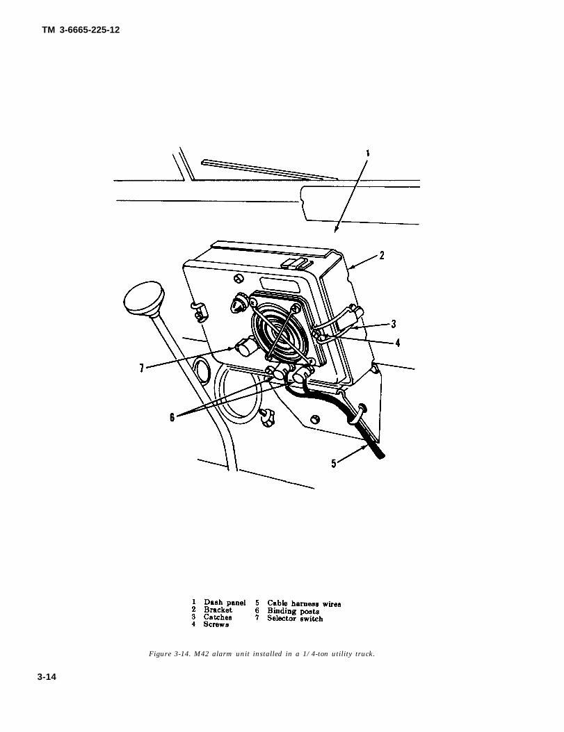
TM 3-6665-225-12
Figure 3-14. M42 alarm unit installed in a 1/4-ton utility truck.
3-14

TM 3-6665-225-12
Figure 3-15. M42 alarm unit installed in a 3/4-ton truck.
3-15

TM 3-6665-225-12
Figure 3-16. Refill kit drawer installed in a 3/4-ton truck.
Figure 3-17. M42 alarm unit installed in a 2 1/2-ton truck.
3-16

TM 3-6665-225-12
Figure 3-18. M42 alarm unit and a BA3517/U battery installed in an armored personnel carrier and recovery vehicle.
3-17

TM 3-6665-225-12
Figure 3-19. Refill kit drawer installed in an armored personnel carrier and recovery vehicle.
3-18

TM 3-6665-225-12
Figure 3-20. M42 alarm unit installed in an armored command and reconnaissance vehicle.
3-19

TM 3-6665-225-12
Figure 3-21. BA3517/U battery installed in an armored reconnaissance vehicle.
Section II. PREVENTIVE MAINTENANCE CHECKS AND SERVICES
3-5. Generala. Purpose. Preventive maintenance checks
and services, table 3-1, are routine procedures formaintaining equipment in top operating condi-tion.
b. "Interval and sequence No." column. Per-form the instructions for each item in the numeri-cal sequence listed at the appropriate interval.
c. “Item to be Inspected-Procedure” column.
d. “Work time” column. The time required toperform each procedure is indicated in manhours(M/H ). Total time required to perform the proce-dures listed for each interval (before, during, andafter operation) is summarized above the columnheadings in table 3-1.
3–6. Mandatory Component ReplacementIntervals
Table 3-2 lists parts of the M43 detector unit (fig.Follow the instructions listed in this column as 1-2) and theindicated in the “Interval and sequence No.” be replacedcolumn. Return defective equipment to organi- replacementzational maintenance through your supervisor. operation.
3-20
M42 alarm unit (fig. 1-5) that mustperiodically by the operator. Theintervals are based on periods of

B-Before OperationTime required: 1.2
TM 3-6665-225-12Table 3-1. Operator and Crew Preventive Maintenance Checks and Services
B
Interval andsequence no.
12
3
4
12
1
1
1
1
23
D
2
A
56
6.1
78
3
2
3
4
5
D-During Operation A-After OperationTime required: 0.1 Time required: 0.9
Item to be inspectedprocedure
M43 DETECTOR UNITCheck exterior for damaged, loose, or missing parts.Check that RAINSHIELD assembly and FLOWMETER are installed in han-
dle and are not damaged.Separate bottom case assembly from detector unit assembly. Inspect for cor-
roded, bent, or broken heater contacts (para 2-6a(3)). Check that detectorcell is properly installed (para 2-6a(4)). Check that pump assembly is se-curely installed (para 2-6a(6)). Check that electronic module is securely in-stalled (para 2-6a(7)). Check for evidence of solution in bottom case as-sembly and around solution reservoir assembly. Wipe bottom case assem-bly dry.
Check pump assembly accumulated hours (DA Form 2408-1) (fig. 2-9). Re-place pump assembly if accumulated hours will exceed 1440 hours duringmission (para 3-14).
Perform appropriate shutdown procedures (para 2-13).Enter operational hours on DA Form 2408-1 (para 2-19).
M42 ALARM UNITInspect exterior for damaged, loose, or missing parts.Perform preoperational procedures (para 2-6b).
BA3517/U BATTERYInspect for damage (para 2-6e(1)).
BB501/U BATTERY AND M168 CABLEInspect and service in accordance with TM 11-6140-203-15-3 (para 2-68(2)).
M10 POWER SUPPLYinspect and service in accordance with TM 3-6665-261-14.
VEHICULAR INSTALLATIONSCheck that mounting hardware is secure to vehicle. Tighten loose compo-
nents.Check that cable connections are secure.Check for frayed insulation or other damage such as bent or defective con-
nector pins.
Worktime
(M/H)
0.10.1
0.1
0.1
0.10.1
0.10.1
0.1
0.1
0.1
0.1
0.10.1
3-6. Mandatory Component Replacement 1-2) and the M42 alarm unit (fig. 1-5) that must beIntervals replaced periodically by the operator. The replace-
Table 3-2 lists parts of the M43 detector unit (fig. ment intervals are based on periods of operation.
Table 3-2. Mandatory Component Replacement Intervals
End Item
M43 detectorunit
M42 alarm
Componentto be
replaced
Pump assemblyReservoirAir filterBA3030 or
IBB3202/UFbatteries
24 hoursper day
60 days12 hours12 hours30 days
Replace after operating for
Less than12 hoursper day
dailydaily30 days
8 hoursor lessper day
dailydaily30 days
Reference
para 3-14para 2-7b
para 2-7cpara 3-16
1440 hours after last 1440-hour service. Refer to daily log DA Form 2408-1 (para 2-19).During operation in sand or dust conditions, replace air filter in accordance with table 2-1.
Section I I I . OPERATOR’S TROUBLESHOOTING3-7. Scope component, unit, or system is followed by a list of
a. This section contains troubleshooting or mal- tests or inspections necessary for you to determinefunction information and tests for locating and cor- probable causes and suggested corrective actionsrecting most of the troubles which may develop in for you to remedy the malfunction.the M43 detector unit and the M42 alarm unit. Each b. This manual cannot list all possible mal-malfunction or trouble symptom for an individual
Change 2 3-21

TM 3-6665-225-12
functions that may occur or all tests or inspections andcorrective actions. If a malfunction is not listed (exceptwhen malfunction and cause are obvious), or is not cor-rected by listed corrective actions, you should notifyhigher level maintenance.
c. Table 3-3 and table 3-4 list the common malfunc-tions that you may find during the operation or mainte-nance of the M43 detector unit and the M42 alarm unit,respectively. You should perform the tests or inspec-
tions and corrective actions in the order listed.
3-8. Disposition of Defective Partsa. When substitution of a replacement pump assem-
bly or electronic module during a test or inspection cor-rects the malfunction, do not discard, but return theoriginal component to organization maintenancethrough your supervisor.
b. Dispose of all other defective components in accor-dance with local standing operating procedures (SOP).
Table 3-3. M43 Detector Unit Troubleshooting Table
MALFUNCTIONTEST OR INSPECTION
CORRECTIVE ACTION
1. SOLUTION IN BOTTOM CASE ASSEMBLYStep 1. Check for loose reservoir assembly.
a. Tighten reservoir assembly using D-ring (fig. 2-3).b. If damaged, prepare solution and install new reservoir assembly (para 2-7b and c).
Step 2. Check for loose or damaged pump assembly.a. Secure latches.b. If damaged, replace pump assembly (para 3-14).
Step 3. Check for improperly installed or damaged detector cell.a. Tighten bail (9, fig. 1-3).b. If damaged replace detector cell (para 3-12).
2 HORN DOES NOT SOUND WHEN POWER SOURCE IS CONNECTEDStep
Step
Step
Step
1.
2.
3.
4.
Check that ZERO ADJUST knob is fully clockwise and HORN VOL-BATTERY TEST control knob is fully clockwise when powersource is connected.
a. Disconnect power source.b. Press in and rotate ZERO ADJUST knob (5, fig. 2-1) fully clockwise and HORN VOL-BATTERY TEST knob (6) fully clock-
wise.c. Wait one minute before reconnecting power source.Press HORN VOL-BATTERY TEST knob (6, fig. 2-1); METER indication must be 24 minimum. If less than 24, proceed as
follows:a Substitute fresh BA3517/U battery or freshly-charged BB501/U battery. Refer to table 1-2 for proper battery applications at
various temperatures.b. Replace electronic module (para 3-13).Inspect cables for frayed or broken insulation, bent or broken connector pins, or other damage that could prevent proper opera-
tion. Replace defective cables.Check ambient air temperaturesIf temperature is below 40°F., perform startup procedures to warm up M43 detector unit.
3. HORN CONTINUE TO SOUND WHEN ZERO ADJUST KNOB IS PRESSED IN.PUMP ASSEMBLY DOES NOT OPERATE.
Step 1. Check that electronic module (10, fig. 1-3) is securely installedRemove and reinstall electronic module (para 3-13).
Step 2. Temporarily substitute replacement electronic module for electronic module in use (pare 3-14).If malfunction is corrected, leave replacement electronic module installed. If not, reinstall original electronic module.
4. PUMP CONTINUES TO OPERATE WHEN HORN SOUNDSStep 1. Temporarily substitute replacement pump assembly for pump assembly in use (para 3-14).
If malfunction is corrected, leave replacement pump assembly installed. If not, reinstall, original pump assembly.Step 2. Temporarily substitute replacement electronic module for electronic module in use (para 3-13).
If malfunction is corrected, leave replacement electronic module installed. If not, reinstall original electronic module.5. PUMP DOES NOT OPERATE WHEN ZERO ADJUST KNOB IS PRESSED IN.
Step 1. Temporarily substitute replacement pump assembly for pump assembly in use (para 3-14).If malfunction is corrected, leave replacement pump assembly installed. If not, reinstall original pump assembly.
Step 2. Temporarily substitute replacement electronic module for electronic module in use (para 3-13).If malfunction is corrected leave replacement electronic module installed. If not, reinstall original electronic module.
6. MET’ER INDICATES MORE THAN 40 VOLTS WHEN HORN-VOL BATTERY TEST KNOB IS PRESSED IN.Step 1. Check that knob is pressed in completely.Step 2. Substitute known good power source and press in HORN VOL-BATTERY TEST knob to check reading.
3-22 Change 1

TM 3-6665-225-12
Table 3-3. M43 detector unit troubleshooting table – continued
MALFUNCTIONTEST OR INSPECTION
CORRECTIVE ACTION
If voltage is still more than 40 volts, substitute replacement electronic
module for electronic module in use (para 3-13); repeat test.
7. FLOWMETER INDICATIONS LOWStep 1.Step 2.Step 3.Step. 4
Step 5.
Step 6.
Step 7.Step 8.
Step 9.
Check that AIR INLET assembly is closed (fig. 2-5, A) and AIR OUTLET port is open (para 2-9a).Check that FLOWMETER is installed properly (para 2-9h).Check that AIR FILTER plug (7, fig. 1-2) is securely tightened.Check air filter for deposits of foreign matter.a. Unscrew plug (4, fig. 2-4).b. Remove air filter and inspect for foreign matter deposited on black side of air filter.c. Replace dirty air filter (para 2-7d(3)).Check for loose reservoir assembly.Tighten reservoir assembly using D-ring (fig. 2-3),Check for loose or damaged detector cell.Tighten bail (9, fig. 1-3).Prepare solution and install new reservoir assembly (para 2-7 b and c).Check that ball in FLOWMETER is not sticking.a. Twist FLOWMETER (2, fig. 2-6) clockwise and remove it from AIR INLET assembly cover (4).b. Hold FLOWMETER horizontal and check that ball moves freely by rocking FLOWMETER from side to side.Temporarily substitute replacement pump assembly in use (para 3-14).If malfunction is corrected, leave replacement pump assembly installed, If not, reinstall original pump assembly.
Step 10. If air temperature is below 40°F., perform startup procedures to warm up M43 detector unit (para 2-15j).8. FLOWMETER INDICATIONS HIGH
Step 1.
Step 2.
9. METERStep 1.Step 2.
Step 3.
Step 4.
Check that air filter is not missing or defective.a. Unscrew plug (4, fig. 2-4).b. Install air falter if necessary (para 2-7d).Temporarily substitute replacement pump assembly for pump assembly in use (para 3-14).If malfunction is corrected, leave replacement pump assembly installed. If not, reinstall original pump assembly.
INDICATION TOO HIGH, ERRATIC, OR MISSINGPress in HORN VOL-BATTERY TEST knob (6, fig. 2-1) and release to check that switch does not stick.Press in ZERO ADJUST knob (5) and rotate counterclockwise to check for indication in blue zone on meter.a. Hold ZERO ADJUST knob pressed in.b. Press in hand crank (2), rotate crank clockwise 50 turns, and release it.
NOTEKeep hand crank in down position, not pressed in.
c. Rotate ZERO ADJUST knob (still pressed in) for indication in blue zone, Release knob.d. If necessary, press and reset. ZERO ADJUST knob after 5 minutes.Temporarily substitute replacement electronic module for electronic module in use (pars 3-13).If malfunction is corrected, leave replacement electronic module installed. If not, reinstall original electronic
module.Temporarily substitute replacement pump assembly for pump assembly in use (pare 3-14).If malfunction is corrected, leave replacement pump assembly installed. If not, reinstall original pump assembly.
10. M43 DETECTOR UNIT DOES NOT RESPOND TO SIMULANT IN SENSITIVITYCHECKStep 1.Step 2.
Step 3.Step 4.
Step 5.Step 6.
BOTTLE WITHIN 5 MINUTESTemporarily substitute replacement detector cell for detector cell in use (para 3-12).Repeat applicable procedures in paragraph 2-9a through p to check response to simulant in sensitivity check
bottle.If malfunction is corrected, leave replacement detector cell installed. If not, reinstall original detector cell,Temporarily substitute replacement pump assembly for pump assembly in use (pare 3-14).Repeat applicable procedures in paragraph 2-9a through p to check response to simulant in sensitivity check
bottle.If malfunction is corrected, leave replacement pump assembly.Temporarily substitute replacement electronic module for electronic module in use (para 3-13).Repeat applicable procedures in paragraph 2-9a through p to check response to simulant in sensitivity check
bottle.If malfunction is corrected, leave replacement electronic module installed, If not, reinstall original electronic
module.
Change 1 3-23

TM 3-6665-225-12
Table 3-4. M42 alarm unit troubleshooting tableMALFUNCTION
TEST OR INSPECTIONCORRECTIVE ACTION
1. ALARM-RED INDICATOR AND LOUDSPEAKER INOPERATIVEStep 1. Position selector switch (8, fig. 1-5) to TEST. If no response, replace batteries (para 3-16).Step 2. Check for damaged telephone cable wires (para 3-2 d) between M42 alarm unit and M43 detector unit or loose con-
nection at binding posts (7, fig. 1-5).a. Replace damaged telephone cable.b. Reconnect loose wires.
2. ALARM-RED INDICATOR FLASHES, BUT LOUDSPEAKER INOPERATIVECheck that selector switch is positioned to HORN ON.Position selector switch to HORN ON.
Section IV. M43 DETECTOR UNIT
3-9. General in chassis assembly.The operator is authorized to replace a defectiveflow rate meter (FLOWMETER), rainshield as-sembly, detector cell, electronic module, andpump assembly.
3-10. FLOWMETERR e m o v e F L O W M E T E R ( 3 , f i g . 1 - 3 ) b yunscrewing it (counterclockwise) from handle (2).Install replacement FLOWMETER by screwingit (clockwise) into handle.
3-11. RAINSHIELD AssemblyRemove RAINSHIELD assembly (1, fig. 1-3) byunscrewing it (counterclockwise) from handle (2).Install replacement RAINSHIELD assembly byscrewing it (clockwise) into handle.
3-12. Detector Cella. Removal. Each new detector cell must be
stabilized after installation. Stabilization isaccomplished during startup and operation (para2-9) .
(1) Release four catches (12, fig. 1-2) fromcatches (13) and separate detector assembly (6)from bottom case assembly (9).
(2) Turn the lobed nut of bail (2, fig. 3-22)counterclockwise and swing bail away fromdetector cell (3).
CAUTIONDo not twist or exert excessive side mo-tion to detector cell during removal ordetector cell ports may be broken andleft in chassis.(3) While rocking detector cell (3) gently,
pull it directly from chassis assembly (1).b. Replacement.
(1) Remove detector cell from its can.Remove plastic bag, two caps, and plug fromdetector cell.
(2) Dampen outside of the two detector cellports with a few drops of water.
(3) Position detector cell (3) so that its portsare alined with their corresponding fittings inchassis assembly (1). Press detector cell into place
1234
Chassis asemblyBailDetector cellTurnlock fastener
567
CatchPump assemblyElectronic module
Figure 3-22. M43 detector unit modular components.
3-24 Change 1

TM 3-6665-225-12
(4) Center bail (2) on bottom of detector cell (3)and turn lobed nut clockwise until fingertight.
(5) Replace detector assembly (6, fig. 1-2) inbottom case assembly (9) and secure four catches(12).
3-13. Electronic Modulea. Removal.
(1) Release four catches (12, fig. 1-2) fromcatches (13) and separate detector assembly (6)from bottom case assembly (9).
(2) Rotate turnlock fastener (4, fig. 3-22) fullycounterclockwise and pull electronic module (7)from its housing on chassis assembly (1).
b. Replacement.(1) Position electronic module (7) so that its
electrical connector will mate with electrical con-nector in chassis assembly (1).
(2) Slide electronic module (7) into housing onchassis assembly (1).
(3) Push turnlock fastener (4) toward chassisassembly (1). Rotate turnlock fastener clockwiseuntil its tip touches housing and electronic module(7) is secured in position.
(4) Replace detector assembly (6, fig. 1-2) inbottom case assembly (9) and secure four catches(12).
3-14. Pump Assemblya. Removal.
(1) Release four catches (12, fig. 1-2) fromcatches (13) and separate detector assembly (6)from bottom case assembly (9).
(2) Release two catches (5, fig. 3-22) on pumpassembly (6).
(3) If necessary, rock pump assembly (6)slightly while pulling it directly away from chassisassembly (1).
(4) Record pump assembly operating hourssince last tubing replacement on modified DA Form2408-1 (para 2-20).
b. Replacement.(1) Dampen outside of the four ports on top of
pump assembly (6) with water.(2) Position pump assembly (6) so that its elec-
trical connector and ports are alined with their re-ceptacles in chassis assembly (1).
(3) Press pump assembly (6) into place in chas-sis. Secure pump assembly in position with twocatches (5).
(4) Replace detector assembly (6, fig. 1-2) inbottom case assembly (9) and secure four catches(12).
(5) Enter the hours when next pump assemblyreplacement is due on M43 daily log (para 2-19).
Section V. M42 ALARM UNIT
3-15. General CAUTION
The operator is authorized to replace batteries in Observe battery polarity as shown on label
the M42 alarm unit.
3-16. Batteriesa. Removal.
(1) Position selector switch (6, fig. 3-23) toHORN OFF.
(2) Loosen four knurled screws (2) and separatechassis assembly (4) from housing (5).
(3) Release spring-tension clip (8) and openhinged cover of the battery retainer (9).
(4) Remove batteries (7) from battery retainer(9).
b. Replacement.
inside battery retainer.(1) Install four BA3030 batteries in battery re-
tainer (9), close hinged cover, and secure it withspring-tension clip (8).
(2) With gasket (10) in place, position chassisassembly (4) in housing (5).
(3) Secure by tightening four knurled screws(2).
c. Test.(1) Position selector switch (6) to TEST. Loud-
speaker (3) will sound and ALARM-RED indicator(1) will flash.
(2) Set selector switch (6) to HORN OFF.
Change 2 3-25

TM 3-6665-225-12
Figure 3-23. M42 alarm unit battery installation.
3-26

TM 3-6665-225-12
CHAPTER 4
ORGANIZATIONAL MAINTENANCE INSTRUCTIONS
Section I. SERVICE UPON RECEIPT OF MATERIEL
4–1. New Materiel solution is clear. Examinea. M43 Detector Unit. Perform procedures in bottles (6) for leaks.
paragraph 2-6a. f. Vehicular Installation
the sensitivity check
Components.b. M42 Alarm Unit. Perform procedures of (1) Installation kit. Forward the installation
paragraph 2-6b. kit to the maintenance facility responsible forc. M10 Power Supply. Perform procedures of installing the components in the vehicle.
paragraph 2-6c. (2) Mounting kit. Forward the mounting kitd. Battery Power Sources. Perform procedures to the maintenance facility responsible for install-
of paragraph 2-6e. ing it on a vehicular installation kit.e. M229 Refill Kit. Discard an M229 refill kit
with an expired date. Unbuckle and discard the 4–2. Used and Reconditioned Materielstrap (2, fig. 1-6) and slide the two drawers (1) Treat used and reconditioned materiel the same asfrom the sleeve (4). Examine the air filter pack- new materiel. Perform the applicable instructionsages for damage. Check that each solution reser- of paragraph 4-1 to insure operational readinessvoir assembly (5) is filled to the mark and that the of the equipment.
Section Il. ORGANIZATIONAL MAINTENANCE TROUBLESHOOTING
4-3. GeneralOrganizational Maintenance is responsible forisolating and replacing defective electrical cablesin vehicular installations.
4-4. Mounting kitsPerform troubleshooting procedures described in
Section III. MONTHLY LOG
4-6. GeneralEquipment Daily or Monthly Log (DA Form2408-1) is used to record and accumulate monthlyoperational hours of an M43 detector unit (fig.1-2). It also provides a means of recordingscheduled and unscheduled servicing of the pumpassembly. Organizational maintenance personnelmust maintain the monthly log.
4–7. Modification and Use of DA Pam
FOR M43 DETECTOR UNIT
2408–1(fig. 4-1)a. The instructions of
4-5c(1) are applicable.b. Block 1. Enter
TM 38-750, paragraph
“DETECTOR UNIT,CHEMICAL AGENT AUTOMATIC ALARM:PORTABLE, M43.”
c. Block 2. Line out “REGISTRATION OR”and enter the M 43 detector’s serial number.
d. Block 3.
the Maintenance section of TM 3-6665-273-20.
4-5. Installation KitsRefer to the chapter in TM 3-6665-274-20applicable to the vehicular installation. Performpost installation checkout and troubleshootinginstructions to isolate the trouble.
(1) Line out “OR LUBRICATION” in block.(2) Block 3a and 3c are not applicable.(3) Block 3b. Enter the hours when the next
pump assembly service is due as indicated by thelast entry on the daily log.
e. Block 4.(1) Enter a check in the monthly block.(2) Block 4a. Enter the month and year.(3) Block 4b. Line out “READING” and add
“ M O N T H L Y . ” Enter the tota l monthlyoperational hours.
(4) Block 4c. Line out “READING MILES”and add “TOTAL HOURS. ” Enter cumulativehours operated.
(5) Columns 4d through 4j are not appli-cable.
(6) Column 4k. Same as TM 38-750 ,paragraph 4-5d (15).
(7) “REMARKS” block. Same as TM38-750, paragraph 4-5d(16).
4-1

TM 3-6665-225-12
Figure 4-1. Sample DA Form 2408-1 modified for recording monthly log.
Section IV. M43 DETECTOR UNIT4–8. General c. Remove and replace defective performed
Authorized repair of the M43 detector unit by packing (4) on adapter (3).
organizational maintenance personnel is limited d. Press adapter (14, fig. 1-3) into rainshield(13) and screw RAINSHIELD assembly (1) intoto replacement of defective gaskets and preformed
packings on the rainshield assembly and flow ratemeter.
4–9. RAINSHIELD Assemblya. Unscrew RAINSHIELD assembly (1, fig.
1-3) from handle (2) and pull rainshield (13) awayfrom adapter (14).
b. Remove and replace defective gasket (2, fig.4-2) on rainshield (1).
handle (2).
4–10. Flow Rate Meter (FLOWMETER)a. Unscrew FLOWMETER (3, fig. 1-3) from
handle (2).b. Remove and replace defective gasket (5, fig.
4-2) from flow rate meter (6).c. Screw FLOWMETER (3, fig. 1-3) into
handle (2).
Section V. M42 ALARM UNIT
4–11. General. of the selector switch knob, knurled screws thatRepair of the M42 alarm unit by organizational secure the panel to the housing, and the ALARM-maintenance personnel is limited to replacement RED indicator lens and lamp.
4-2

TM 3-6665-225-12
Figure 4-2. RAINSHIELD assembly and flow rate meter components.
4–12. Selector Switch Knob(fig. 4-3)a. Rotate knob (7) fully clockwise.b. Loosen two setscrews (6) and remove knob
(7) from selector switch shaft.c. Position replacement knob (7) on selector
switch shaft so that its pointer is at HORN ON.d. Tighten two setscrews (6) to secure knob (7)
to shaft.
4–13. Knurled Screws(fig. 4-3)a. Unscrew defective screw (3) from housing (8)
and then from chassis assembly (1).b. Remove packing (2).c. Replace screw (3) by reversing order of dis-
assembly (a and b above).
4–14. ALARM-RED Indicator Lens and Lamp(fig. 4-3)a. Unscrew lens (4) and remove lamp (5) after
pressing it in and turning it counterclockwise.b. Replace defective lamp (5) or lens (4) by
reversing order of removal.
4-3

TM 3-6665-225-12
Figure 4-3. M42 alarm unit, exploded view.
4-4

TM 3-6665-225-12
CHAPTER 5PREPARATION FOR SHIPMENT AND ADMINISTRATIVE STORAGE
Section I. PREPARATION FOR SHIPMENT
5-1 M43 Detector Unita. General. Before the M43 detector unit is shipped to
another organization, it must be cleared of residualsolution and inspected, the meter and handcrank mustbe protected from damage, and all ports must be closed.
b. Procedure.(1) Disconnect power source from 24 VDC INPUT
connector (11, fig. 1-2).(2) Release four catches (12) and remove detector
unit assembly (6) from bottom case assembly (9).CAUTION
Keep weight assembly free from dirt afterremoving reservoir assembly.
(3) Hold detector unit assembly upright by its han-dle (2, fig. 1-3) and unscrew reservoir assembly (12).Allow the weight assembly (12.1) to hang down. If solu-tion is in reservoir assembly, discard it in accordancewith standing operating procedures.
CAUTIONUse only distilled water (4 or 5, table 1-3)when preparing the detector unit assemblyfor shipment. Use of water which containsimpurities will cause damage to the detectorcell.
(4) Rinse reservoir assembly with distilled water (4or 5, table 1-3) and fill it approximately two-thirds withdistilled water.
(5) Center reservoir assembly under weight assem-bly and screw reservoir assembly (12) into mountinghole in chassis (4). Insure a tight seal by turning reser-voir assembly D-ring clockwise.
(6) Check that seal (1, fig. 1-4) is correctly seated ingroove around top of bottom case assembly (9, fig. 1-2).Assemble detector unit assembly (6) to bottom case as-sembly (9) and secure four catches (12).
(7) Remove AIR OUTLET CAP (15) from port.(8) Remove electrical connector cover (10) from 24
VDC INPUT receptacle (11).(9) Check that AIR INLET assembly is in CLOSED
position (fig. 2-5, A). Unscrew plug (1).(10) Attach power source connector to the 24 VDC
INPUT connector (11, fig. 1-2). If horn (3, fig. 2-1)sounds, press ZERO ADJUST knob (5) and rotate itfully counterclockwise.
(11) Press handcrank (2) in, rotate the handcrank50 turns, and release it. Do not pull the handcrank out.
(12) Allow M43 detector unit to run for 4 minutes.Then disconnect power source from the 24 VDC INPUTconnector (11, fig. 1-2).
(13) Release four catches (12) and remove detectorunit assembly (6) from bottom case assembly (9).
(14) Hold detector unit assembly upright by itshandle (2, fig. 1-3) and unscrew reservoir assembly (12).
(15) Discard contents of reservoir assembly (12)and screw empty reservoir assembly into mountinghole in chassis (4).
(16) Install detector unit assembly (6, fig. 1-2) inbottom case assembly (9) and secure it with fourcatches (12).
(17) Install AIR OUTLET cap (15) in AIR OUT-LET port.
(18) Screw plug (1, fig. 2-5) into AIR INLET assem-bly. Check that AIR INLET assembly is set toCLOSED.
(19) Install electrical connector cover (10, fig. 1-2)on 24 VDC INPUT connector (11).
(20) Pull up handcrank (19) to storage position.(21) Using figure 5-1 as a guide, fabricate a ship-
ping guard from corrugated cardboard. After cuttingPIECE B from PIECE A, fold PIECE B in half andslide it over the extended handcrank shaft. SecurePIECE B in position with PIECE A as shown in figure5-1 to protect the meter window and keep thehandcrank in the storage position.
(22) Release catch (12, fig. 1-2) on BA3517/U bat-tery, if applicable, and remove the battery before ship-ping the M43 detector unit.
5-2. M42 Alarm Unita General. Before the M42 alarm unit is shipped to
another organization, remove the four batteries.b. Procedure.
(1) Remove the batteries as described in paragraph3-16a.
(2) Close hinged cover and secure it with spring-tension clip (8).
(3) With gasket (10) in place, position chassis as-sembly (4) in housing (5).
(4) Secure by tightening four knurled screws (2).
Change 1 5-1

TM 3-6665-225-12
Figure 5-1. Shipping guard fabrication and installation diagram.
Section II. ADMINISTRATIVE STORAGE
5-3. M43 Detector Unit 5-4. M42 Alarm UnitPrepare the M43 detector unit for storage in the same Prepare the M42 alarm unit for storage in the samemanner as it is prepared for shipment (para 5-1). manner as it is prepared for shipment (para 5-2).
5-2 Change 1
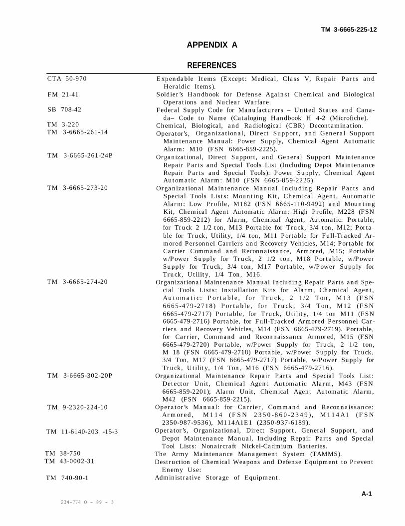
TM 3-6665-225-12
APPENDIX A
REFERENCESCTA 50-970
FM 21-41
SB 708-42
TM 3-220TM 3-6665-261-14
TM 3-6665-261-24P
TM 3-6665-273-20
TM 3-6665-274-20
TM 3-6665-302-20P
TM 9-2320-224-10
TM 11-6140-203 -15-3
TM 38-750TM 43-0002-31
TM 740-90-1
Expendable Items (Except: Medical, Class V, Repair Parts andHeraldic Items).
Soldier’s Handbook for Defense Against Chemical and BiologicalOperations and Nuclear Warfare.
Federal Supply Code for Manufacturers – United States and Cana-da– Code to Name (Cataloging Handbook H 4-2 (Microfiche).
Chemical, Biological, and Radiological (CBR) Decontamination.Operator’s, Organizational, Direct Support, and General Support
Maintenance Manual: Power Supply, Chemical Agent AutomaticAlarm: M10 (FSN 6665-859-2225).
Organizational, Direct Support, and General Support MaintenanceRepair Parts and Special Tools List (Including Depot MaintenanceRepair Parts and Special Tools): Power Supply, Chemical AgentAutomatic Alarm: M10 (FSN 6665-859-2225).
Organizational Maintenance Manual Including Repair Parts andSpecial Tools Lists: Mounting Kit, Chemical Agent, AutomaticAlarm: Low Profile, M182 (FSN 6665-110-9492) and MountingKit, Chemical Agent Automatic Alarm: High Profile, M228 (FSN6665-859-2212) for Alarm, Chemical Agent, Automatic: Portable,for Truck 2 1/2-ton, M13 Portable for Truck, 3/4 ton, M12; Porta-ble for Truck, Utility, 1/4 ton, M11 Portable for Full-Tracked Ar-mored Personnel Carriers and Recovery Vehicles, M14; Portable forCarrier Command and Reconnaissance, Armored, M15; Portablew/Power Supply for Truck, 2 1/2 ton, M18 Portable, w/PowerSupply for Truck, 3/4 ton, M17 Portable, w/Power Supply forTruck, Utility, 1/4 Ton, M16.
Organizational Maintenance Manual Including Repair Parts and Spe-cial Tools Lists: Installation Kits for Alarm, Chemical Agent,Automatic: Portable, for Truck, 2 1/2 Ton, M13 (FSN6665-479-2718) Portable, for Truck, 3/4 Ton, M12 (FSN6665-479-2717) Portable, for Truck, Utility, 1/4 ton M11 (FSN6665-479-2716) Portable, for Full-Tracked Armored Personnel Car-riers and Recovery Vehicles, M14 (FSN 6665-479-2719). Portable,for Carrier, Command and Reconnaissance Armored, M15 (FSN6665-479-2720) Portable, w/Power Supply for Truck, 2 1/2 ton,M 18 (FSN 6665-479-2718) Portable, w/Power Supply for Truck,3/4 Ton, M17 (FSN 6665-479-2717) Portable, w/Power Supply forTruck, Utility, 1/4 Ton, M16 (FSN 6665-479-2716).
Organizational Maintenance Repair Parts and Special Tools List:Detector Unit, Chemical Agent Automatic Alarm, M43 (FSN6665-859-2201); Alarm Unit, Chemical Agent Automatic Alarm,M42 (FSN 6665-859-2215).
Operator’s Manual: for Carrier, Command and Reconnaissance:Armored, M114 (FSN 2350-860-2349) , M114A1 (FSN2350-987-9536), M114A1E1 (2350-937-6189).
Operator’s, Organizational, Direct Support, General Support, andDepot Maintenance Manual, Including Repair Parts and SpecialTool Lists: Nonaircraft Nickel-Cadmium Batteries.
The Army Maintenance Management System (TAMMS).Destruction of Chemical Weapons and Defense Equipment to Prevent
Enemy Use:Administrative Storage of Equipment.
A-1234-774 O - 89 - 3

TM 3-6665-225-12
APPENDIX B
BASIC ISSUE ITEMS LIST AND ITEMS TROOP INSTALLED OR AUTHORIZED LIST
Section I. INTRODUCTION
B–1. ScopeThis appendix lists basic issue items and itemstroop installed or authorized required by thecrew/operator for operation of the M8 and M10through M18 alarm systems.
B–2. GeneralThis Basic Issue Items and Items Troop Installedor Authorized List is divided into the followingsections:
a. Section II—Basic Issue Items List. N o tapplicable.
b. Section III–Items Troop Installed or Au-thorized List.This section lists in alphabetical sequence, itemswhich at the discretion of the unit commandermay accompany the end item but should not beturned in with the end item.
B-3. Explanation of ColumnsThe following provides an explanation of columnsfound in the tabular listings:
a. National Stock Number. Indicates theNational Stock Number assigned to the item andwill be used for requisitioning purposes.
b. Part Number. Indicates the primary numberused by the manufacturer, which controls the de-sign and characteristics of the item by means ofits engineering drawings, specifications stand-ards, and inspection requirements to identify anitem or range of items.
NOTEWhen a stock numbered item isrequisitioned, the repair part receivedmay have a different part number thanthe part being replaced.
c. Federal Supply Code for Manufacturer(FSCM). The FSCM is a 5-digit numeric codelisted in SB 708-42 which is used to identify themanufacturer, distributor, or Governmentagency, etc.
d. Description. Indicates the Federal itemname and, if required, a minimum description toidentify the item.
e. Unit of Measure (U/M). Indicates thestandard of the basic quantity of the listed item asused in performing the actual maintenance func-tion. This measure is expressed by a two-char-acter alphabetical abbreviation. When the unit ofmeasure differs from the unit of issue, the lowestunit of issue that will satisfy the required units ofmeasure will be requisitioned.
f. Quantity Authorized. Indicates the quantityof the item authorized to be used with the equip-ment.
B-4. Abbreviations
Abbreviations ExplanationAWG American Wire Gagecond conductor(s)F FahrenheitW with
B-1

TM 3-6665-225-12
SECTION Ill. ITEMS TROOP INSTALLED OR AUTHORIZED LIST
B-2 Change 2

TM 3-6665-225-12
APPENDIX C
C–1. GeneralThe maintenance allocation chart, section II, liststhe authorized maintenance functions assignedthe maintenance categories for maintenance of theM8 and M10 through M18 alarm systems. Thischart is to be used by all levels of maintenance toinsure complete support of the equipment.
C–2. Maintenance functions.Maintenance functions are limited to and definedas follows:
a. Inspect. To determine the serviceability ofan item by comparing its physical, mechanical, orelectrical characteristics with established stand-ards through examination.
b. Test. To verify serviceability and detectincipient failure by measuring the mechanical orelectrical characteristics of an item and comparingthose characteristics with prescribed standards.
c. Service. Operations required periodically tokeep an item in proper operating condition, i.e., toclean, to paint, and replace M229 Refill Kitcomponents in the M43 Detector Kit.
d. Adjust. To maintain, within prescribedlimits, by bringing into proper or exact position,or by setting the operating characteristics tospecified parameters.
e. Install. The act of emplacing, seating, orfixing into position an item, part, or module in amanner to allow the proper functioning of anequipment or system.
f. Replace. The act of substituting a service-able like type assembly, or module for an unserv-iceable counterpart.
g. Repair. The application of maintenanceservices or other maintenance actions to restoreserviceability to an item by correcting specificdamage, fault, malfunction, or failure in a part,subassembly, module end item, or system.
h. Overhaul. That maintenance e f for tnecessary to restore an item to a completely serv-iceable or operational condition as prescribed bymaintenance standards in appropriate technicalpublications. Overhaul is normally the highestdegree of maintenance performed by the Army.Overhaul does not normally return an item to likenew condition.
C-3. Column entriesEntries for these columns are explained below:
a. Column 1, Group Number. Column 1 listsgroup numbers, the purpose of which is toidentify components, assemblies, subassemblies,and modules with the next higher assembly.
b. Column 2, Component/Assembly. Column 2contains the noun names of components, assem-blies, subassemblies, and modules for whichmaintenance is authorized.
c. Column 3, Maintenance Functions. Column3 lists the functions to be performed on the itemlisted in Column 2.
d. Column 4. Maintenance Category. Column 4specifies, by the listing of a “work time” (WT)figure in the appropriate subcolumns, the lowestlevel of maintenance authorized to perform thefunction listed in Column 3. This figure representsthe active time required to perform that mainte-nance function at the indicated category of main-tenance. If the number or complexity of the taskswithin the listed maintenance function vary atdifferent maintenance categories, appropriate“work time” figures are shown for each category.The number of man-hours specified by “worktime” figure represents the average time requiredto restore an item to a serviceable condition undertypical field operating conditions. This time in-cludes preparation time, troubleshooting time,and quality assurance/quality control time inaddition to the time required to perform thespecific tasks identified for the maintenance func-tions authorized in the maintenance allocationchart. This time is expressed in man-hours andcarried to one decimal place (tenths of hours).
e. Column 5. Tools and Equipment. Column 5specifies by code, those common tool sets andspecial tools, test, and support equipment re-quired to perform the designated function.
C-4. Tool and Test Equipment RequirementsList — Section Ill
This list identifies all tools and test equipment re-quired for maintenance and repair of the M8 andM10 through M18 Alarm Systems as specified inthe maintenance allocation chart. The list givestool or test equipment reference codes, user main-
C–1
MAINTENANCE ALLOCATION CHART
Section I. INTRODUCTION

TM 3-6665-225-12
tenance category codes, a short description of chart. The maintenance category code indicatesitems required, and national stock numbers. The the level of availability and authorized use. Alltool or test equipment code corresponds to the remaining columns are self-explanatory.code in Column 5 of the maintenance allocation
C-2

TM 3-6665-225-12
Section Il. MAINTENANCE ALLOCATION CHARTFOR
Alarm, Chemical Agent, Automatic: portable; M8, M10 through M18
C - 3

TM 3-6665-225-12
C-4

TM 3-6665-225-12
C-5

TM 3-6666-225-12
SECTION Ill. Alarm, Chemical Agent, Automatic: portable; M8, M10 through M18
C-6
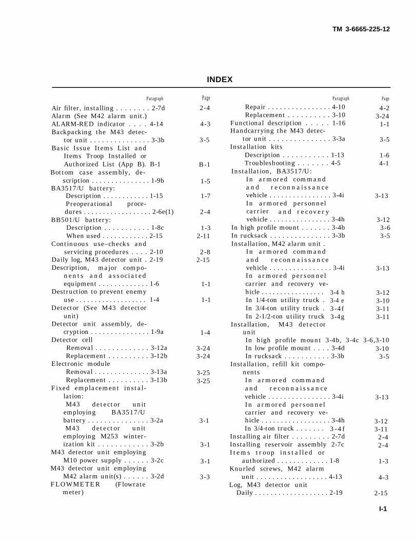
TM 3-6665-225-12
INDEX
Paragraph
Air filter, installing . . . . . . . . 2-7dAlarm (See M42 alarm unit.)ALARM-RED indicator . . . . 4-14Backpacking the M43 detec-
tor unit . . . . . . . . . . . . . . . 3-3bBasic Issue Items List and
Items Troop Installed orAuthorized List (App B). B-1
Bottom case assembly, de-scription . . . . . . . . . . . . . . . 1-9b
BA3517/U battery:Description . . . . . . . . . . . . 1-15Preoperational proce-dures . . . . . . . . . . . . . . . . . . 2-6e(1)
BB501/U battery:Description . . . . . . . . . . . 1-8cWhen used . . . . . . . . . . . . 2-15
Continuous use–checks andservicing procedures . . . . 2-10
Daily log, M43 detector unit . 2-19Description, major compo-
nents and associatedequipment . . . . . . . . . . . . . 1-6
Destruction to prevent enemyuse . . . . . . . . . . . . . . . . . . . 1-4
Detector (See M43 detectorunit)
Detector unit assembly, de-cryption . . . . . . . . . . . . . . . 1-9a
Detector cellRemoval . . . . . . . . . . . . . 3-12aReplacement . . . . . . . . . . 3-12b
Electronic moduleRemoval . . . . . . . . . . . . . . 3-13aReplacement . . . . . . . . . . 3-13b
Fixed emplacement instal-lation:M43 detector unit
employing BA3517/Ubattery . . . . . . . . . . . . . . . 3-2aM43 detector unit
employing M253 winter-ization kit . . . . . . . . . . . . 3-2b
M43 detector unit employingM10 power supply . . . . . . 3-2c
M43 detector unit employingM42 alarm unit(s) . . . . . . 3-2d
FLOWMETER (Flowratemeter)
Page2-4
4-3
3-5
B-1
1-5
1-7
2-4
1-32-11
2-82-15
1-1
1-1
1-4
3-243-24
3-253-25
3-1
3-1
3-1
3-3
Paragraph
Repair . . . . . . . . . . . . . . . . 4-10Replacement . . . . . . . . . . 3-10
Functional description . . . . . 1-16Handcarrying the M43 detec-
tor unit . . . . . . . . . . . . . . . 3-3aInstallation kits
Description . . . . . . . . . . . 1-13Troubleshooting . . . . . . . 4-5
Installation, BA3517/U:In armored commandand reconnaissancevehicle . . . . . . . . . . . . . . . . 3-4iIn armored personnelcarrier and recoveryvehicle . . . . . . . . . . . . . . . . 3-4h
In high profile mount . . . . . . . 3-4bIn rucksack . . . . . . . . . . . . . . . 3-3bInstallation, M42 alarm unit .
In armored commandand reconnaissancevehicle . . . . . . . . . . . . . . . . 3-4iIn armored personnelcarrier and recovery ve-hicle . . . . . . . . . . . . . . . . .In 1/4-ton utility truck .In 3/4-ton utility truck .In 2-1/2-ton utility truck
Installation, M43 detectorunit
3-4 h3-4 e3-4f3-4g
Page
4-23-24
1-1
3-5
1-64-1
3-13
3-123-63-5
3-13
3-123-103-113-11
In high profile mount 3-4b, 3-4c 3-6,3-10In low profile mount . . . . 3-4dIn rucksack . . . . . . . . . . . 3-3b
Installation, refill kit compo-nentsIn armored commandand reconnaissancevehicle . . . . . . . . . . . . . . . . 3-4iIn armored personnelcarrier and recovery ve-hicle . . . . . . . . . . . . . . . . . . 3-4hIn 3/4-ton truck . . . . . . . 3 -4 f
Installing air filter . . . . . . . . . 2-7dInstalling reservoir assembly 2-7cItems troop installed or
authorized . . . . . . . . . . . . . 1-8Knurled screws, M42 alarm
unit . . . . . . . . . . . . . . . . . . 4-13Log, M43 detector unit
Daily . . . . . . . . . . . . . . . . . . . 2-19
3-103-5
3-13
3-123-11
2-42-4
1-3
4-3
2-15
I-1

TM 3-6665-225-12
ParagraphMonthly . . . . . . . . . . . . . . . .4-6
Maintenance allocation chart(app C)
Mandatory component re-placement intervals . . . . . 3-6
Monthly log for M43 detectorunit . . . . . . . . . . . . . . . . . .4-6
Mounting kits:Description . . . . . . . . . . . 1-12Preoperationalprocedures . . . . . . . . . . . 2-6eTroubleshooting . . . . . . .4-4
M8 alarm system:Backpacking . . . . . . . . . . 3-3bDescription . . . . . . . . . . . 1-7Handcarrying . . . . . . . . . 3-3a
M10 alarm system:Description . . . . . . . . . . . 1-7bFixed emplacement . . . . 3-2c
M10 power supplyControls . . . . . . . . . . . . . . 2-4aDescription . . . . . . . . . . . 1-11Installation . . . . . . . . . . . 3-2cInstruments . . . . . . . . . . 2-b
M11 alarm system:Description . . . . . . . . . . . 1-7c
Page4-1
3-20
4-1
1-6
2-44-1
3-51-13-5
1-33-1
2-11-63-12-1
1-3
Page
Vehicular installation 3-4a (1), 3-4b, 3-b ,3-63-4c, 3-4e 3-10, 3-11
M12 alarm system:Description . . . . . . . . . . . 1-7c 1-3Vehicular installation 3-4a(2), 3-4b, 3-b, 3-6
3-4c, 3-4f 3-10, 3-11M13 alarm system:
Description . . . . . . . . . . . 1-7c 1-3Vehicular installation 3-4(3), 3-4b 3-6
3-4c, 3-4g 3-10, 3-11M14 alarm system:
Description . . . . . . . . . . . 1-7d 1-3Vehicular installation 3-4a(4), 3-4d, 3-6, 3-10
3-4 h 3-12
M15 alarm system:Description . . . . . . . . . . . 1-7d 1-3Vehicular installation . . . 3-4a(5), 3-4d, 3-6
3-4 i 3-13M16 alarm system . . . . . . . . . 1-7e 1-3M17 alarm system . . . . . . . . . 1-7e 1-3M18 alarm system . . . . . . . . . 1-7e 1-3M42 alarm unit:
Administrative storage . 5-4 5-2ALARM-RED indicatorlens and lamp . . . . . . . . . 4-14 4-3Battery removal . . . . . . . 3-16a 3-25Battery replacement . . . .3-16b 3-25Control . . . . . . . . . . . . . . . 2-3a 2-1Description . . . . . . . . . . . 1-10 1-5
I-2
ParagraphInstruments . . . . . . . . . . 2-3bKnurled screws . . . . . . . . 4-13Preoperationalprocedures . . . . . . . . . . . 2-6bPreparation for shipment 5-2Selector switch knobreplacement . . . . . . . . . . 4-12Test . . . . . . . . . . . . . . . . . 3-16c
M43 detector unit:Administrative storage . 5-3Controls . . . . . . . . . . . . . . 2-2aDescription . . . . . . . . . . . 1-9Detector Cell . . . . . . . . . . 3-12Electronic module . . . . . . 3-13Flowmeter . . . . . . . . . . . . 3-10Instruments . . . . . . . . . . 2-2bPreoperationalProcedures . . . . . . . . . . . 2-6aPre-startup procedures . 2-7Pump assembly . . . . . . . . 3-14RAINSHIELDassembly . . . . . . . . . . . . . . 3-11Startup and operation . . 2-9
M168 cableDescription . . . . . . . . . . . 1-8c (2)Preoperationalprocedures . . . . . . . . . . . 2-6e (2)Use . . . . . . . . . . . . . . . . . . 2-15
M182 mounting kits, descrip-tion 1-12 b
M228 mounting kit, descrip-tion 1-12a
M229 refill kit, description . . 1-14M253 winterization kit:
Description . . . . . . . . . . . 1-8cPreoperationalprocedures . . . . . . . . . . . 2-6e (2)
Operational alert . . . . . . . . . . . 2-11Operation under unusual
conditions:In blowing sand or dust . 2-18In rain or sleet . . . . . . . . . 2-16In snow . . . . . . . . . . . . . . 2-17In temperatures below40°F . . . . . . . . . . . . . . . . . . 2-15In tropical environments 2-14
Operation under usual condi-tions:Preoperational pro-cedures . . . . . . . . . . . . . . 2-6Pre-startup procedures . 2-7Startup and operation . . 2-9
Preventive Maintenancechecks and services . . . . 3-5
Preparation for shipmentM42 alarm unit . . . . . . . . 5-2
2-14-3
2-35-1
3-25
5-22-11-3
3-243-243-242-1
2-32-4
3-25
3-242-6
1-3
2-42-11
1-6
1-61-6
1-3
2-42-9
2-142-142-14
2-112-10
2-22-42-6
3-20
5-1

Paragraph Page Paragraph
M43 detector unit . . . . . . 5-1Pump assembly
Removal . . . . . . . . . . . . . . 3-14aReplacement . . . . . . . . . . 3-14b
RAINSHIELD assemblyRepair . . . . . . . . . . . . . . . .4-9Replacement . . . . . . . . . . 3-11
Reactivating alarm systemafter operational alert . . 2-12
Record and report forms . . . . 1-2References (app A)Reservoir assembly , in -
stalling . . . . . . . . . . . . . . . 2-7cScope . . . . . . . . . . . . . . . . . . . . 1-1Solution, preparing . . . . . . . . 2-7bStartup and operation . . . . . . 2-9Shutdown for more than 72
hours . . . . . . . . . . . . . . . . . 2-13aShutdow procedures . . . . . . . 2-13
5-1
3-253-25
4-23-24
2-101-1
2-41-12-42-6
2-102-10
Shutdown for 72 hours or lessSelector switch knob . . . . . . .
TM 3-6665-225-12
Page
2-13 b 2-104-12 4-3
Service upon receipt of mate-riel:
New materiel . . . . . . . . . . . . 4-1Used and reconditioned
materiel . . . . . . . . . . . .4-2System configuration . . . . . . . 1-7Tabulated data . . . . . . . . . . . . 1-17Troubleshooting
Operator’s . . . . . . . . . . . . 3-8Organizational mainte-nance . . . . . . . . . . . . . . . . 4-3
Vehicular system instal-lations . . . . . . . . . . . . . . . 3-4
Winterization kitDescription . . . . . . . . . . . 1-8cPreoperationalprocedures . . . . . . . . . . . 2-6e(2)
4-1
1-11-7
3-22
4-1
3-5
1-3
2-4
I-3

TM 3-6665-225-12
By Order of the Secretary of the Army:
Official:VERNE L. BOWERSMajor General, United States ArmyThe Adjutant General
FRED C. WEYANDGeneral, United States ArmyChief of Staff
Distribution:To be distributed in accordance with DA Form 12-28, (qty rqr block no. 193) Operator maintenance
requirements for Detection and Warning Systems, Alarms.
U.S. GOVERNEMENT PRINTING OFFICE : 1989 - 234-774 (01 538)


THE METRIC SYSTEM AND EQUIVALENTS

PIN: 025846-000

This fine document...
Was brought to you by me:
Liberated Manuals -- free army and government manuals
Why do I do it? I am tired of sleazy CD-ROM sellers, who take publicly available information, slap “watermarks” and other junk on it, and sell it. Those masters of search engine manipulation make sure that their sites that sell free information, come up first in search engines. They did not create it... They did not even scan it... Why should they get your money? Why are not letting you give those free manuals to your friends?
I am setting this document FREE. This document was made by the US Government and is NOT protected by Copyright. Feel free to share, republish, sell and so on.
I am not asking you for donations, fees or handouts. If you can, please provide a link to liberatedmanuals.com, so that free manuals come up first in search engines:
<A HREF=http://www.liberatedmanuals.com/>Free Military and Government Manuals</A>
– SincerelyIgor Chudovhttp://igor.chudov.com/
– Chicago Machinery Movers