Embed Size (px)
Citation preview

OPERATORING MANUAL
H44-1

2
OPERATORING MANUAL AUTOMATIC COATING MACHINE
HARLACHER H44-1
Serial No. 44.6789 max. Frame size (outer) 1600 mm x 1400 mm (width x height) Date of manufacturing 06.2017
Software SPS V 101 / Display V 1.0 Electrical connection 1 x 230 V (+6/-10%) + N + PE 50 / 60 Hz Power consumption / current 0.5 kW / 3.5 A Compressed air connection (dry) 6 to 8 bar, max. 5 litre / min. Noise emission below 70 dB Colours white RAL 9010 / blue RAL 5017 Options none
Observe
Before connecting and / or using the above-mentioned machine, you must read this manual completely and carefully to avoid any injuries!
HARLACHER AG Lauenenstrasse 51-53 CH - 3855 Brienz Switzerland Tel +41 33 827 02 10 Fax +41 33 827 02 15 [email protected] www.harlacher.swiss

3
Register
Valid from Serial No. 44.6788
Section 1 Seite 1 General information 5 1.1 Range of application 5 1.2 Correct length of coating troughs 2 Safety regulations 5 2.1 Introduction 5 2.2 Warning and danger signs 6 3 Installation and commissioning testes 6
3.1 Location of the machine 6 3.2 Transport and unpacking 7
3.3 Installation and assembly 7 3.4 Electrical connection 8 3.5 Compressed air supply 8 3.6 Performance tests 9 4 Manual mode 11 5 Setting up and preparation 13 5.1 Centring the screens 13 5.2 Setting the zero point of the coating carriage 14 5.3 Trough selection / fill with emulsion 14 6 Programming 15 6.1 General 15 6.2 Entering a program / set-up mode 15 6.3 Language selection 16 7 Automatic mode 17 7.1 General 17 7.2 Coating 17

4
8 Interrupting a running program 18 9 Function monitoring and error messages 18 10 Maintenance 18 10.1 General 18
10.2 Periodic controls, cleaning and greasing roster 18
11 Annotated diagrams 19 11.1 Overview H44-1 19 11.2 Operating panel 20 Section 2 Wiring diagrams 21 12.2017
5
1 General information 1.1 Range of application
This machine is intended to coat flat screen printing stencils vertically with photo-emulsion. It will coat coarse to fine mesh made of polyester, nylon or stainless steel, attached to suitable printing frames. With max. specified dimensions (outside) shown on the front page of the manual. The min. screen tension for photo-emulsion is approx. 10 N/cm.
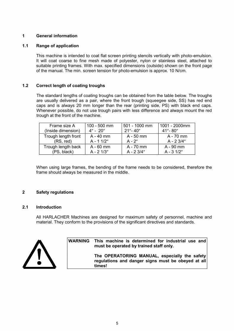
1.2 Correct length of coating troughs The standard lengths of coating troughs can be obtained from the table below. The troughs
are usually delivered as a pair, where the front trough (squeegee side, SS) has red end caps and is always 20 mm longer than the rear (printing side, PS) with black end caps. Whenever possible, do not use trough pairs with less difference and always mount the red trough at the front of the machine.
Frame size A
(Inside dimension) 100 - 500 mm 4” - 20”
501 - 1000 mm 21”- 40”
1001 - 2000mm 41”- 80”
Trough length front (RS, red)
A - 40 mm A - 1 1/2”
A - 50 mm A - 2”
A - 70 mm A - 2 3/4”
Trough length back (PS, black)
A - 60 mm A - 2 1/3”
A - 70 mm A - 2 3/4”
A - 90 mm A - 3 1/2”
When using large frames, the bending of the frame needs to be considered, therefore the frame should always be measured in the middle.
2 Safety regulations 2.1 Introduction
All HARLACHER Machines are designed for maximum safety of personnel, machine and material. They conform to the provisions of the significant directives and standards.
WARNING This machine is determined for industrial use and must be operated by trained staff only.
The OPERATORING MANUAL, especially the safety
regulations and danger signs must be obeyed at all times!

6
2.2 Warning and danger signs
3 Installations and commissioning tests 3.1 Location of the machine
The location of the machine should be determined according to the following aspects:
- Room without direct sun light or with covered windows - yellow light - hard, vibration free floor - short distance between the coating machine and the drying compartment - dust free environment, constant room temperature and humidity
The required space for the machine depends on its size and type.
- The space between the rear side of the machine and a wall must be at least 500 mm. - on both sides of the towers, a space of 650 mm must be kept free for maintenance
access. - there should be about 200 mm of free space above the machine for erection and
maintenance - The space left free in front of the machine should be enough to operate the machine and
for easy handing of the frames.
DIRECTIONS Information about technical requirements. Disobeying directions may lead machine failure or loss of material
CAUTION Points of danger which may lead to damage of the machine and / or light to medium injuries
WARNING Points of danger which may lead to serious injuries and / or permanent physical damages

7
3.2 Transport and unpacking
Move the crates as close as possible to the final location of the machine. Carefully open the
wide front side of the crate and carefully check the contents for damage. In case of shipping damages or losses, immediately stop unpacking and contact HARLACHER AG. or its agent, the transport company, transport insurance to get further instructions.
Remove the H44-1 carefully with the fork lift. To ensure that the machine does not tip over,
we recommend that the upper console be fixed to the fork lift. Place some packing material, bubble plastic or a blanket on the fork lift to avoid damage to the H44-1. If there are damages or missing parts, please contact HARLACHER AG or their agent as soon as possible.
3.3 Installation and assembly
The HARLACHER H44-1 is delivered fully assembled. After unpacking and adjusting, the machine can be connected and the commissioning tests may be started.
Place the machine in its final location. The screw feet can be used to compensate for slight unevenness in the floor and to level the machine.
Test if the coating carriage is level in both sides and adjust the screw feet appropriately. Connect the cable for the foot pedal (12) under the lower frame holder, to the appropriate plug at the back control tower. Now an appropriately qualified person must electrically and pneumatically connect the machine.
WARNING Suitable equipment must be used for lifting
and transporting the crates and heavy machine parts!
WARNING Suitable equipment must be used to transport heavy machine parts.

8
3.4 Electrical connection
3.5 Compressed air connection
Connect only clean and dry compressed air, with a minimal pressure of 5 bar (ideal approx. 6-8 bar) to the inlet. Check for adjusted pressure with the manometer on the inside of the control tower and correct to a min. of 5 bar if necessary. A water collector is mounted under the regulator (to empty; press the button). A pressure switch is also found in this unit, this stops the machine if the pressure drops below 4 bar.
Coating trough pressure: coating troughs are pressed the against the mesh individually by
means of a pressure regulator and pneumatic cylinders. This force can be adjusted to suite the application.
In general: the longer the troughs are, the higher the pressure
used should be. Suggested bandwidth: 3 - 5 bar
WARNING The electrical connection must be done by a licensed electrician in accordance with the supplied diagram and the specifications on page 1 of the manual.
CAUTION Shut off the air supply hose before the pneumatic plug and socket is connected and secured with the clasps. The hose can now be connected at the back of the control tower. Please note that the main switch has no effect on the compressed air supply. It is vital that the compressed air is unplugged from the machine before any work on the pneumatics is undertaken.

9
3.6 Performance test
Enter the manual mode via the menu.
Once in Manual mode, press the "M" sign to open the pop-up menu for the respective motors. The motor for the coating carriage is signalled at the bottom of the machine (home position coating carriage) and the motor for the upper frame holder is signalled at the top of the machine.
CAUTION All limit switches have been factory adjusted and tested. Due to safety regulation, all the functions must be checked carefully prior to operating the machine! Check limit switch functions with short movements near the switch (only in manual mode)

10
Use the curser keys on the pop-up menu to move the coating carriage in the appropriate direction. Single cursor is for slow movements and double cursor is for fast movements. Move the coating carriage onto the lower limit switch using the single cursor.
Repeat the process with the upper frame holder.
Both limit switches are symbolised on the side tower of the machine (right tower on the screen). If the limit switch is activated, it is symbolised with a red light. If the limit switch is not activated, it is symbolised with a green light. Note that the clamps need to be open to move the upper frame holder and closed to move the coating carriage. Clamps are operated by pressing the symbol of the available clamps. By pressing a clamp symbol on the screen, the clamps will open/close and the symbol with show the actual status of the clamps.
11
4 Manual mode
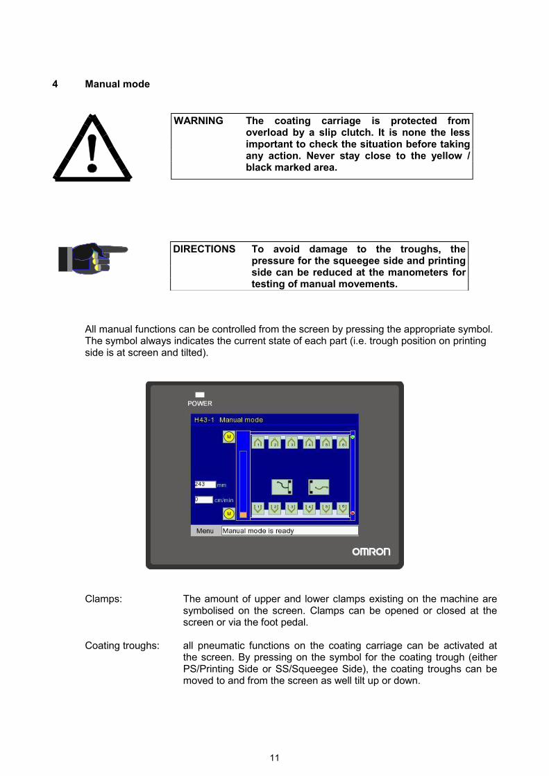
All manual functions can be controlled from the screen by pressing the appropriate symbol. The symbol always indicates the current state of each part (i.e. trough position on printing side is at screen and tilted).
Clamps: The amount of upper and lower clamps existing on the machine are symbolised on the screen. Clamps can be opened or closed at the screen or via the foot pedal.
Coating troughs: all pneumatic functions on the coating carriage can be activated at
the screen. By pressing on the symbol for the coating trough (either PS/Printing Side or SS/Squeegee Side), the coating troughs can be moved to and from the screen as well tilt up or down.
WARNING The coating carriage is protected from overload by a slip clutch. It is none the less important to check the situation before taking any action. Never stay close to the yellow / black marked area.
DIRECTIONS To avoid damage to the troughs, the pressure for the squeegee side and printing side can be reduced at the manometers for testing of manual movements.
12
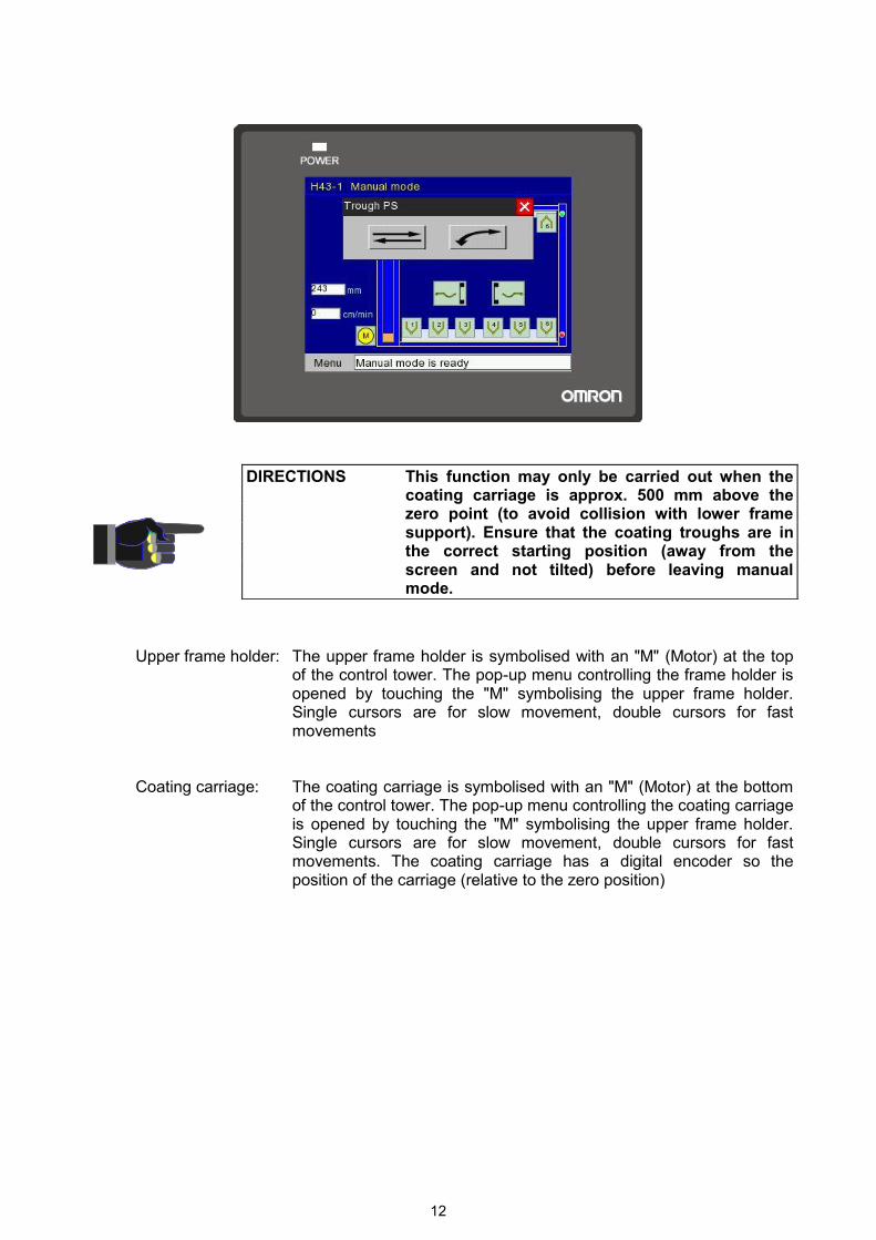
Upper frame holder: The upper frame holder is symbolised with an "M" (Motor) at the top of the control tower. The pop-up menu controlling the frame holder is opened by touching the "M" symbolising the upper frame holder. Single cursors are for slow movement, double cursors for fast movements
Coating carriage: The coating carriage is symbolised with an "M" (Motor) at the bottom of the control tower. The pop-up menu controlling the coating carriage is opened by touching the "M" symbolising the upper frame holder. Single cursors are for slow movement, double cursors for fast movements. The coating carriage has a digital encoder so the position of the carriage (relative to the zero position)
DIRECTIONS This function may only be carried out when the coating carriage is approx. 500 mm above the zero point (to avoid collision with lower frame support). Ensure that the coating troughs are in the correct starting position (away from the screen and not tilted) before leaving manual mode.

13
5. Setting up and preparation
Before coating any screens, the machine needs to be prepared as follows: 5.1 Centring the screens
The frames must be centred sideway in the lower guide rail of the machine. At the top, the frame is supported by means of the clamps in the upper frame holder, after opening the clamps, they can be shifted to suite any frame size. For this, the screws need to be loosened. In the case of more than two clamps, the clamps can be distributed symmetrically over the frame with. Tighten the screws to fix the clamps but make sure not tighten them too much.
CAUTION Correct adjustment of the machine to the frame size is important to avoid damage to machine and material as well as to maintain perfect coating results.
DIRECTIONS Always insert the screens with the mesh facing the rear. Wherever possible user portrait rather than landscape format.
14
For coating a series of screens with the same format, the supplied stopper can be positioned on the upper fame holder. In this way, the screens in one series can be centred easily and time effectively.
Hold the frame, centred and upright, with the mesh facing the rear end of the machine. Now
the upper frame holder can be driven down carefully. The clamps are to be closed with the foot pedal or directly at the screen.
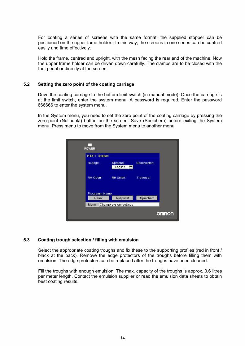
5.2 Setting the zero point of the coating carriage
Drive the coating carriage to the bottom limit switch (in manual mode). Once the carriage is at the limit switch, enter the system menu. A password is required. Enter the password 666666 to enter the system menu. In the System menu, you need to set the zero point of the coating carriage by pressing the zero-point (Nullpunkt) button on the screen. Save (Speichern) before exiting the System menu. Press menu to move from the System menu to another menu.
5.3 Coating trough selection / filling with emulsion Select the appropriate coating troughs and fix these to the supporting profiles (red in front /
black at the back). Remove the edge protectors of the troughs before filling them with emulsion. The edge protectors can be replaced after the troughs have been cleaned.
Fill the troughs with enough emulsion. The max. capacity of the troughs is approx. 0,6 litres
per meter length. Contact the emulsion supplier or read the emulsion data sheets to obtain best coating results.
15
6 Programming 6.1 General
There are 99 automatic, individually adjustable programming positions available. Parameters selected remain in the program until they are rewritten or deleted in the system menu. The only non-programmable values are the individually adjustable coating trough pressures. These can be adjusted by utilising the 2 pressure regulators at the control unit.
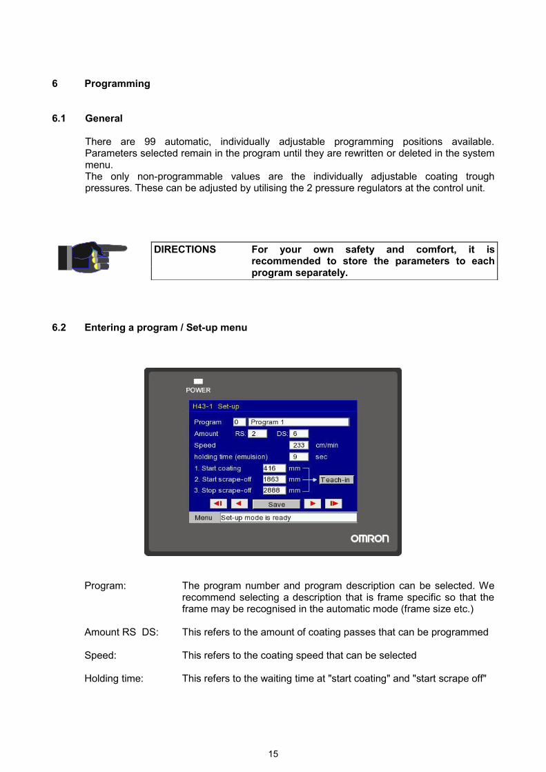
6.2 Entering a program / Set-up menu
Program: The program number and program description can be selected. We recommend selecting a description that is frame specific so that the frame may be recognised in the automatic mode (frame size etc.)
Amount RS DS: This refers to the amount of coating passes that can be programmed Speed: This refers to the coating speed that can be selected Holding time: This refers to the waiting time at "start coating" and "start scrape off"
DIRECTIONS For your own safety and comfort, it is recommended to store the parameters to each program separately.

16
Teach-in: This refers to the desired coating area of the specific screen being programmed. The positions can be entered by moving the carriage to the appropriate point and the pressing teach pos. 1, 2 or 3 or by entering the exact point by means of the key-pad
The program must be saved before exiting the Set-up menu. 6.3 Language selection
The language can be selected in the system menu. A password is required. Enter the password 666666 to enter the system menu. In the System menu, the language can be selected. Save (Speichern) before exiting the System menu. Press menu to move from the System menu to another menu.

17
7 Automatic mode 7.1 General
Before starting any program, all preparations in point 5 (and possibly further preparation, depending on the program) must be completed.
The following requirements need to be met before starting a program, otherwise the program will not run and “machine not ready” will be displayed: - all clamps must be closed - the upper frame holder may not rest on the end switch - the coating carriage must be on the end switch
7.2 Coating
Select the program no. and press ok. Press start to start the coating program. - Coating carriages drives up and stops at the start coating point. - one or both coating troughs move to the mesh and are tilted - during the programmed “holding time”, the emulsion moves towards the mesh - When the holding time is through, coating begins with the programmed speed - the coating carriage stops at the start scrape-off point and the troughs are tilted down.
The holding time allows the emulsion to run back in the trough. - the coating troughs are slowly scraped off the mesh until the stop scrape-off point is
reached - the troughs move out to the start position - the carriage moves at a set speed to the start a new coating or to end the program The amount of coating passes, coating speed and position as well as clamp positions are all shown on the screen during the running of the program.

18
8 Interrupting a running program The coating program can be sopped by pressing the stop button or by pressing the
emergency switch.
9 Function monitoring All functions are always monitored and constantly displayed in the text line at the bottom of
the screen. 10 Maintenance 10.1 General
The machine should always be kept clean and dry, especially after spilling emulsion. The spilled emulsion should be cleaned immediately and thoroughly dried. Blank metal pieces need to be lightly oiled or greased.
10.2 Periodic controls, cleaning and greasing roster
daily: - wash coating troughs immediately after use
weekly: - control water separator in the control tower and if necessary empty it by pressing the
button - Visually check all movable parts, the tension of the toothed belt and the horizontal
position of the carriage and frame holder monthly: - all guiding rails must be cleaned and greased with “Molykote grease Longterm W2“ - Piston rods of the pneumatic cylinders as well the linear guides to the coating trough
holder must be greased slightly with e.g. “WD 40“
DIRECTION If the maintenance instructions are followed carefully, the machine will work satisfactorily over a long period of time. Disregarding these instructions may lead to a guarantee regress.
WARNING Collision damages must be checked and repaired immediately. If you are in doubt, please contact HARLACHER Ltd. or their agents for assistance.
19
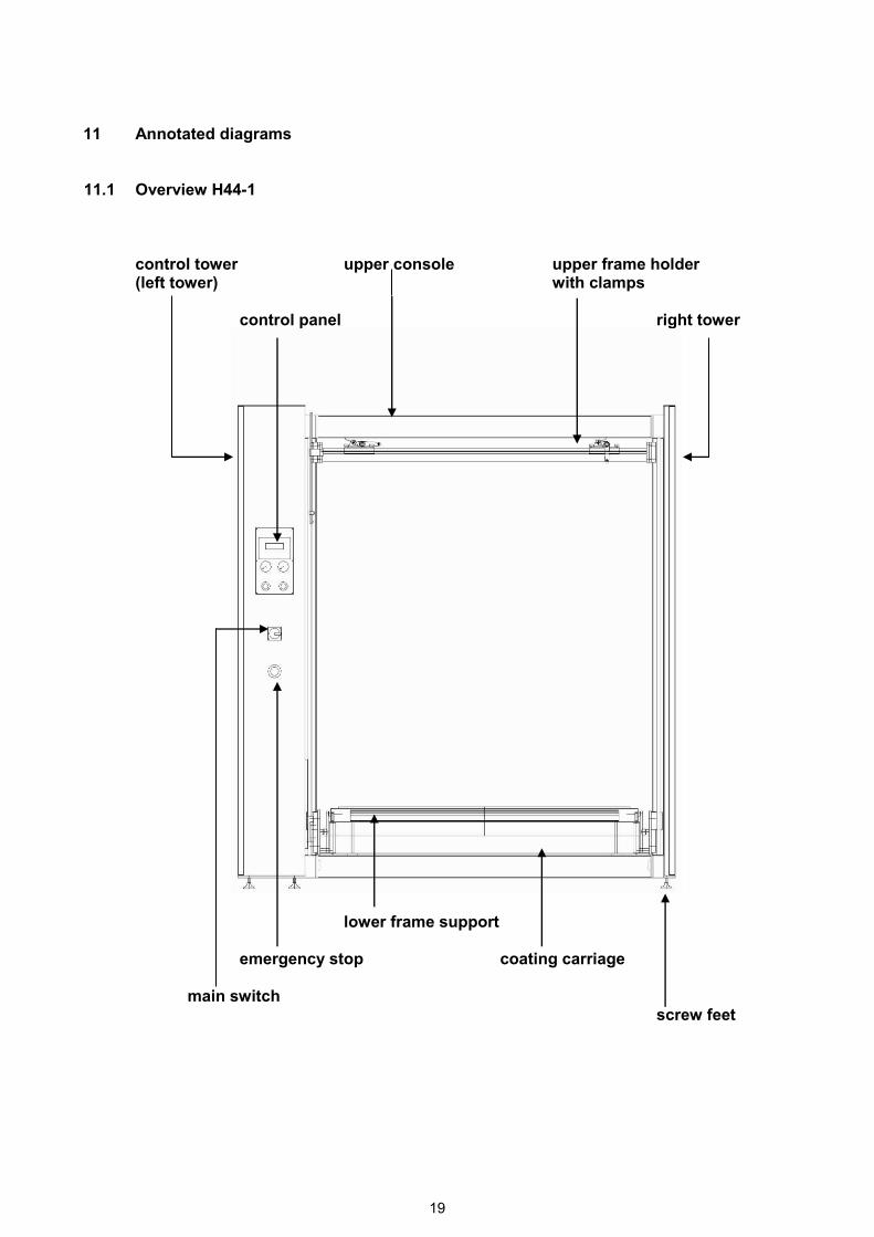
11 Annotated diagrams 11.1 Overview H44-1
control tower upper console upper frame holder (left tower) with clamps control panel right tower
lower frame support emergency stop coating carriage main switch
screw feet

20
11.2 Operating panel
HMI Touch Screen
Manometer und pressure regulator Manometer und pressure regulator
for coating trough pressure on the for coating trough pressure on the printing side (the back coating trough) squeegee side (the front coating trough)

21
WIRING DIAGRAM
H44-1
Automatic Coating Machine
HARLACHER AG Lauenenstrasse 51-53 CH - 3855 Brienz Switzerland Tel +41 33 827 02 10 Fax +41 33 827 02 15 [email protected] www.harlacher.swiss