Embed Size (px)
Citation preview
Product No.: Multiple
Book No.: 1271058-02 V3
Operator’s Manual
Self-cleaning Hermetic Separators
A MRPX 614HGV-14CC MRPX 614HGV-74CH MRPX 614HGV-74CW MRPX 614HGV-74C
A MRPX 714HGV-14CB MRPX 714HGV-14CC MRPX 714HGV-74CH MRPX 714 HGV-74CW MRPX 714HGV-74CB BRPX 714HGV-34CD MRPX 714HGV-34C
C MRPX 518HGV-74CH MRPX 518HGV-74CW MRPX 518HGV-74C
B MRPX 618HGV-14CC MRPX 618HGV-74CF MRPX 618HGV-74CH MRPX 618HGV-74CW MRPX 618HGV-74CB BRPX 618HGV-34CD MRPX 618HGV-34C
H MRPX 718HGV-74CW MRPX 718HGV-74C
H MRPX 818HGV-74C
B MRPX 818HGV-14C B BRPX 818HGV-34C H MRPX 818HGV-74CW MRPX 818HGV-74C
Product No.:
881208-01-01881208-01-01881208-01-01881208-01-01
881208-02-01881208-02-01881208-02-01881208-02-01881208-02-01881208-02-01881208-02-01
881209-01-01881209-01-01881209-01-01
881209-02-01881209-02-01881209-02-01881209-02-01881209-02-01881209-02-01881209-02-01
881209-03-01881209-03-01
881210-01-01
881210-01-02881210-01-02881210-01-02881210-01-02
Alfa Laval Separation ABSeparator Manuals, dept. SKELS-147 80 Tumba, Sweden
Telephone: +46 8 53 06 50 00Telefax: +46 8 53 03 10 40
Printed in Sweden, 99-12
© Alfa Laval Separation AB 1999
This publication or any part thereof may not be reproduced or transmitted by any process or means without prior written permission of Alfa Laval Separation AB.
als and observe the ation, operation, ce.
ctions can result in
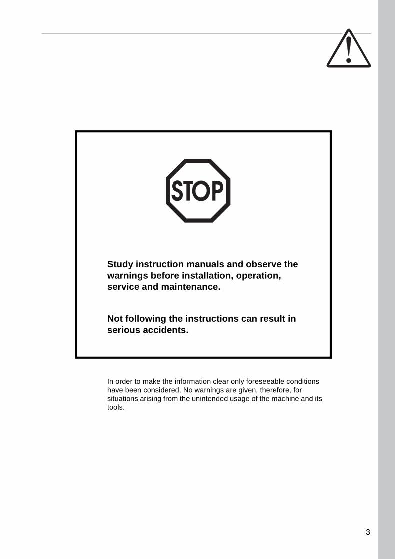
clear only foreseeable conditions ings are given, therefore, for
ended usage of the machine and its
Study instruction manuwarnings before installservice and maintenan
Not following the instruserious accidents.
In order to make the informationhave been considered. No warnsituations arising from the uninttools.
3

4
Contents
1 Safety Instructions 7
2 Separation process 13
2.1 Basic principles 15
2.2 General 16
3 Mechanical function 19
3.1 Identification and safety signson the machine 20
3.2 Power transmission 23
3.3 Brake 26
3.4 Speed indication 26
3.5 Outlet / inlet (twin phase separators) 28
3.6 Outlet / inlet (single phase separators) 30
3.7 Axial seals – cooling system 31
3.8 Bowl 33
4 Sediment discharge function 35
4.1 Function description 36
4.2 Operating water module compact (OWMC) 38
5 Installation and first start 41
5.1 Preparations 42
5.2 Before first start 43
5.3 First start 44
5.4 Operation 44
5.5 Stopping 46
6 Cleaning 47
6.1 Check of cleaning 48
5
7 Operating routine 51
7.1 Check points 52
8 Trouble tracing 55
8.1 Mechanical function 56
8.2 Sediment discharge function 59
8.3 Axial seals 61
6
1 Safety Instructions
G00
1041
1
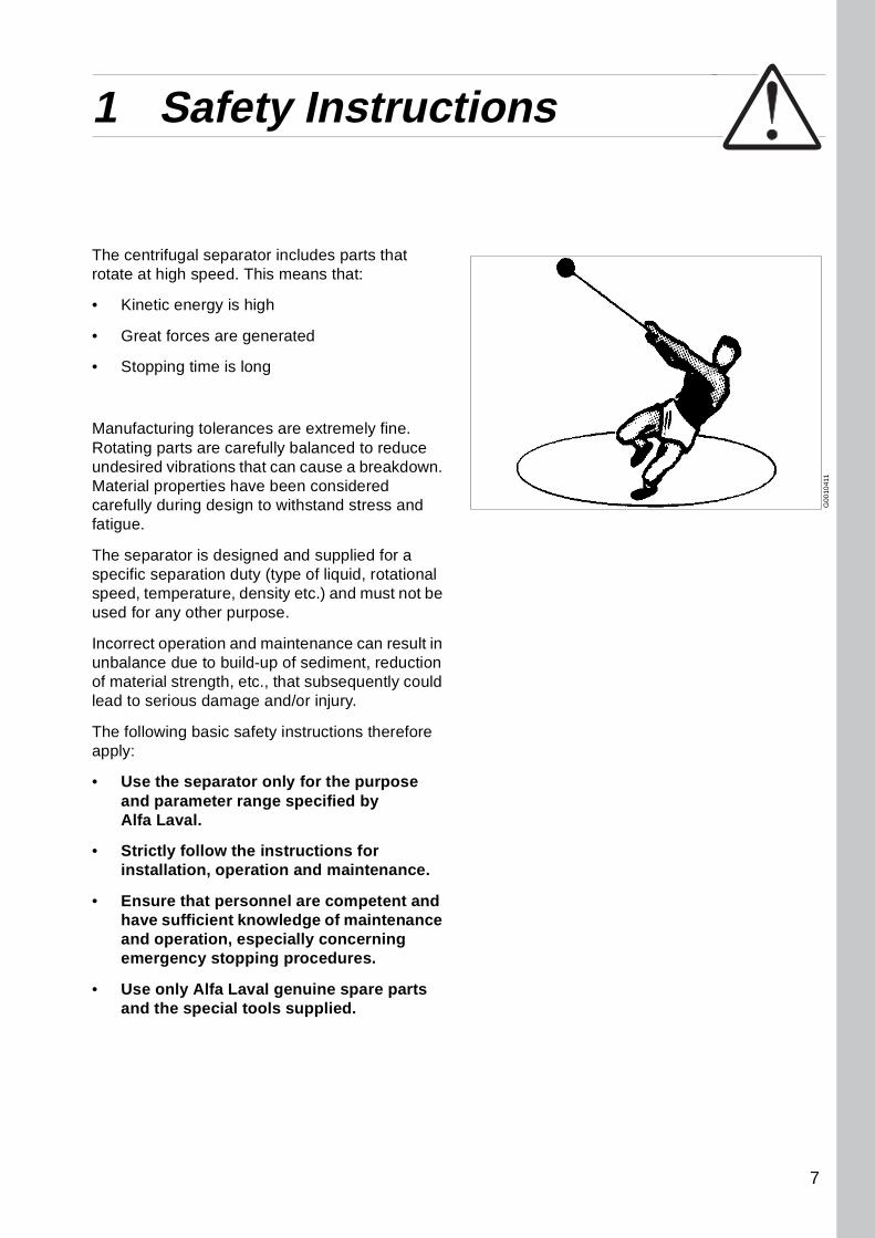
The centrifugal separator includes parts that rotate at high speed. This means that:
• Kinetic energy is high
• Great forces are generated
• Stopping time is long
Manufacturing tolerances are extremely fine. Rotating parts are carefully balanced to reduce undesired vibrations that can cause a breakdown. Material properties have been considered carefully during design to withstand stress and fatigue.
The separator is designed and supplied for a specific separation duty (type of liquid, rotational speed, temperature, density etc.) and must not be used for any other purpose.
Incorrect operation and maintenance can result in unbalance due to build-up of sediment, reduction of material strength, etc., that subsequently could lead to serious damage and/or injury.
The following basic safety instructions therefore apply:
• Use the separator only for the purpose and parameter range specified by Alfa Laval.
• Strictly follow the instructions for installation, operation and maintenance.
• Ensure that personnel are competent and have sufficient knowledge of maintenance and operation, especially concerning emergency stopping procedures.
• Use only Alfa Laval genuine spare parts and the special tools supplied.
7
1 Safety Instructions
S00
513
11S
005
5611
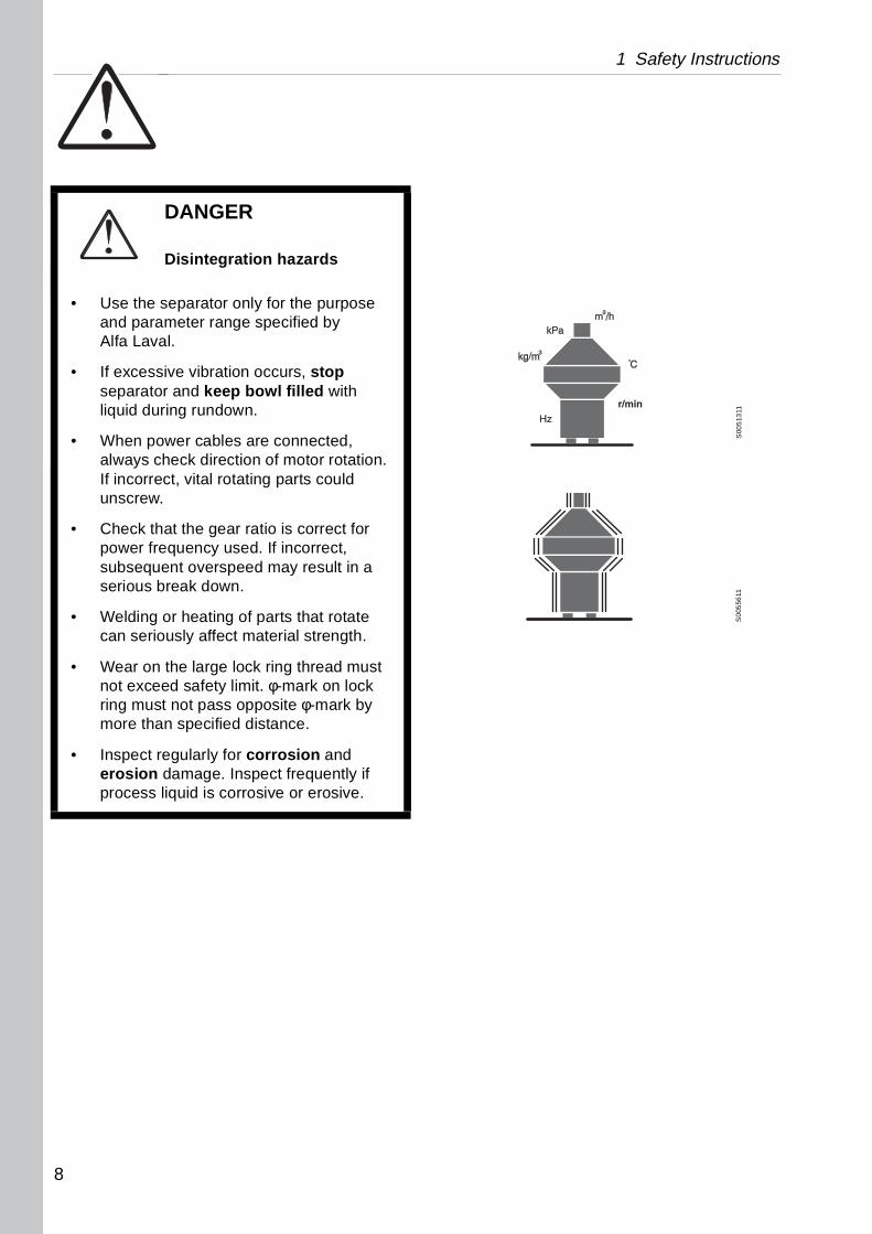
DANGER
Disintegration hazards
• Use the separator only for the purpose and parameter range specified by Alfa Laval.
• If excessive vibration occurs, stop separator and keep bowl filled with liquid during rundown.
• When power cables are connected, always check direction of motor rotation. If incorrect, vital rotating parts could unscrew.
• Check that the gear ratio is correct for power frequency used. If incorrect, subsequent overspeed may result in a serious break down.
• Welding or heating of parts that rotate can seriously affect material strength.
• Wear on the large lock ring thread must not exceed safety limit. φ-mark on lock ring must not pass opposite φ-mark by more than specified distance.
• Inspect regularly for corrosion and erosion damage. Inspect frequently if process liquid is corrosive or erosive.
8
1 Safety Instructions
S0
0511
11S
0051
011
S00
5171
1S
005
161
1
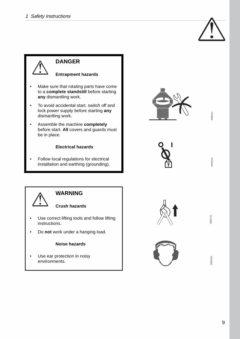
DANGER
Entrapment hazards
• Make sure that rotating parts have come to a complete standstill before starting any dismantling work.
• To avoid accidental start, switch off and lock power supply before starting any dismantling work.
• Assemble the machine completely before start. All covers and guards must be in place.
Electrical hazards
• Follow local regulations for electrical installation and earthing (grounding).
WARNING
Crush hazards
• Use correct lifting tools and follow lifting instructions.
• Do not work under a hanging load.
Noise hazards
• Use ear protection in noisy environments.
9
1 Safety Instructions
S00
554
11S
005
431
1
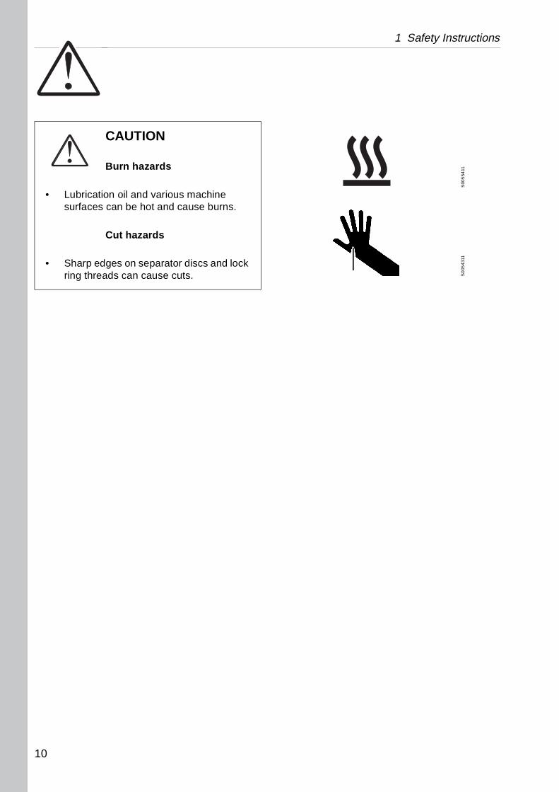
CAUTION
Burn hazards
• Lubrication oil and various machine surfaces can be hot and cause burns.
Cut hazards
• Sharp edges on separator discs and lock ring threads can cause cuts.
10
1 Safety Instructions
Warning signs in the text
Pay attention to the safety instructions in this manual. Below are definitions of the three grades of warning signs used in the text where there is a risk for injury to personnel.
DANGER
Type of hazard
This type of safety instruction indicates a situation which, if not avoided, could result in fatal injury or fatal damage to health.
WARNING
Type of hazard
This type of safety instruction indicates a situation which, if not avoided, could result in disabling injury or disabling damage to health.
CAUTION
Type of hazard
This type of safety instruction indicates a situation which, if not avoided, could result in light injury or light damage to health.
NOTE
This type of instruction indicates a situation which, if not avoided, could result in damage to the equipment.
11
1 Safety Instructions
12
2 Separation process
Contents
2.1 Basic principles 15
2.1.1 Separation by gravity 15
2.1.2 Centrifugal separation 15
2.2 General 16
2.2.1 Throughput 17
2.2.2 Light phase 18
2.2.3 Air penetration / inlet pressure 18
13
2 Separation process
14
2 Separation process 2.1 Basic principles
G0
0107
11
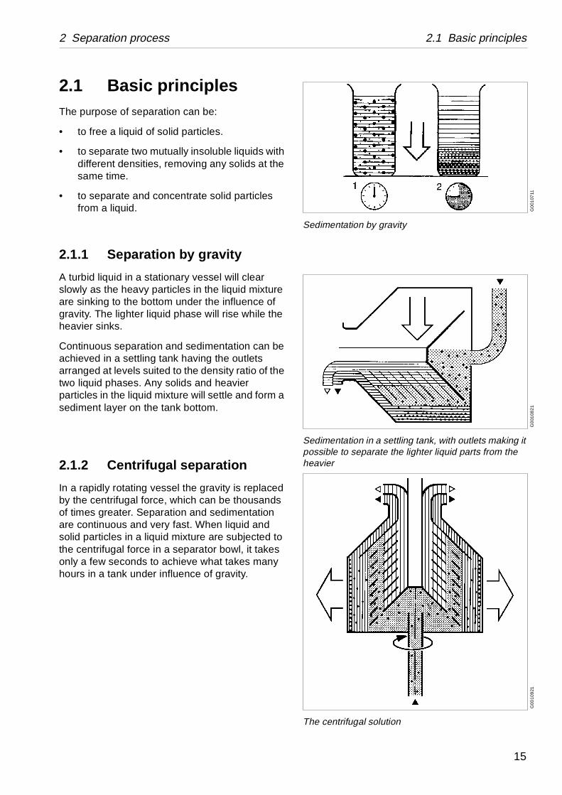
Sedimentation by gravity
G0
0108
21
Sedimentation in a settling tank, with outlets making it possible to separate the lighter liquid parts from the heavier
G00
109
21
The centrifugal solution
2.1 Basic principlesThe purpose of separation can be:
• to free a liquid of solid particles.
• to separate two mutually insoluble liquids with different densities, removing any solids at the same time.
• to separate and concentrate solid particles from a liquid.
2.1.1 Separation by gravity
A turbid liquid in a stationary vessel will clear slowly as the heavy particles in the liquid mixture are sinking to the bottom under the influence of gravity. The lighter liquid phase will rise while the heavier sinks.
Continuous separation and sedimentation can be achieved in a settling tank having the outlets arranged at levels suited to the density ratio of the two liquid phases. Any solids and heavier particles in the liquid mixture will settle and form a sediment layer on the tank bottom.
2.1.2 Centrifugal separation
In a rapidly rotating vessel the gravity is replaced by the centrifugal force, which can be thousands of times greater. Separation and sedimentation are continuous and very fast. When liquid and solid particles in a liquid mixture are subjected to the centrifugal force in a separator bowl, it takes only a few seconds to achieve what takes many hours in a tank under influence of gravity.
15
2.2 General 2 Separation process
G06
9572
1
2.2 General
Twin phase separators
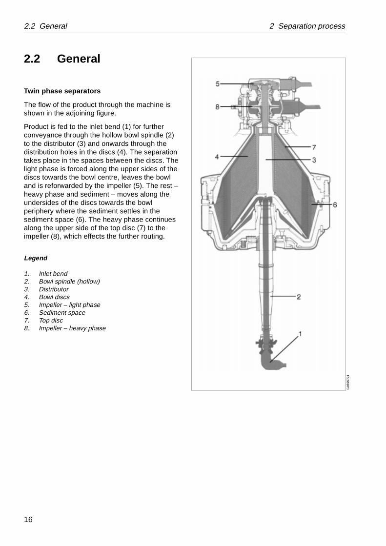
The flow of the product through the machine is shown in the adjoining figure.
Product is fed to the inlet bend (1) for further conveyance through the hollow bowl spindle (2) to the distributor (3) and onwards through the distribution holes in the discs (4). The separation takes place in the spaces between the discs. The light phase is forced along the upper sides of the discs towards the bowl centre, leaves the bowl and is reforwarded by the impeller (5). The rest – heavy phase and sediment – moves along the undersides of the discs towards the bowl periphery where the sediment settles in the sediment space (6). The heavy phase continues along the upper side of the top disc (7) to the impeller (8), which effects the further routing.
Legend
1. Inlet bend2. Bowl spindle (hollow)3. Distributor4. Bowl discs5. Impeller – light phase6. Sediment space7. Top disc8. Impeller – heavy phase
16
2 Separation process 2.2 General
G0
6957
11
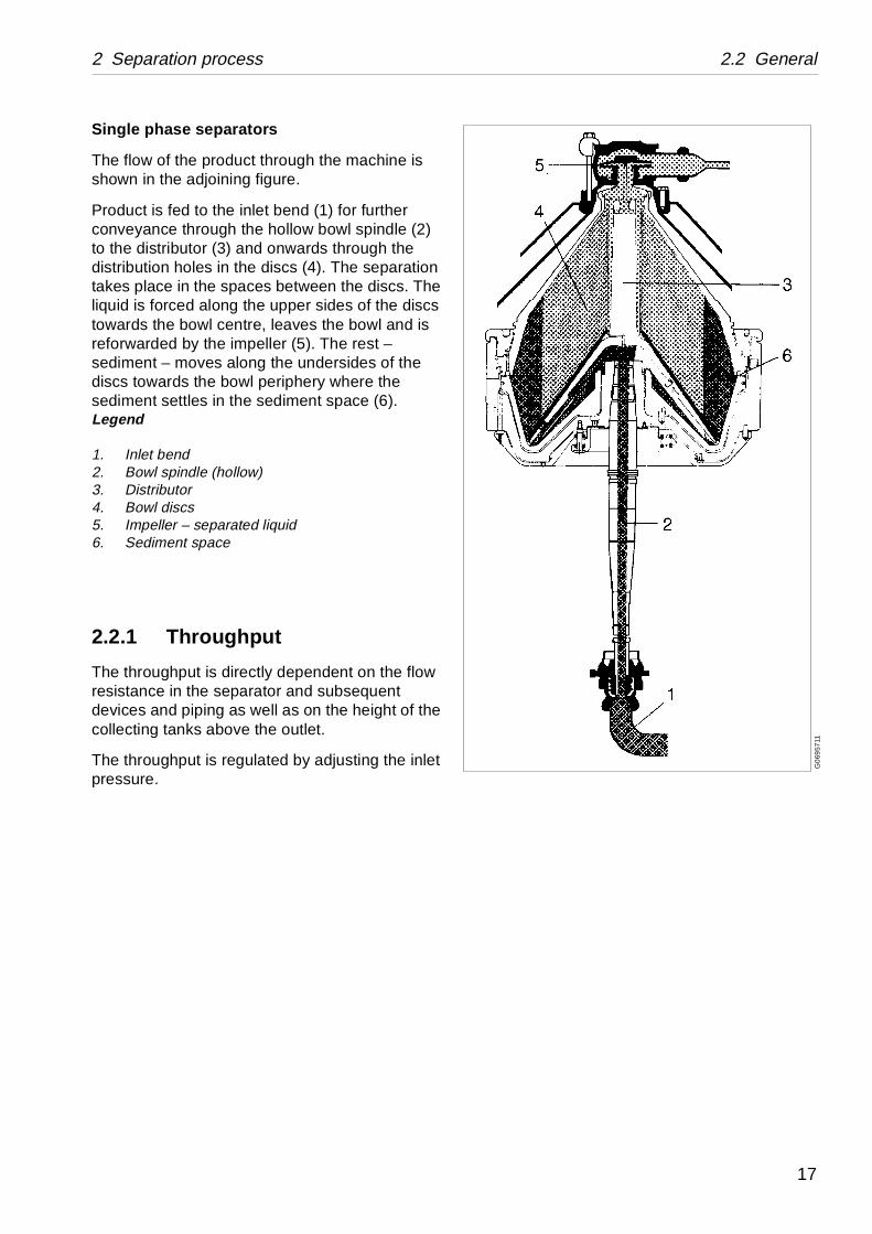
Single phase separators
The flow of the product through the machine is shown in the adjoining figure.
Product is fed to the inlet bend (1) for further conveyance through the hollow bowl spindle (2) to the distributor (3) and onwards through the distribution holes in the discs (4). The separation takes place in the spaces between the discs. The liquid is forced along the upper sides of the discs towards the bowl centre, leaves the bowl and is reforwarded by the impeller (5). The rest – sediment – moves along the undersides of the discs towards the bowl periphery where the sediment settles in the sediment space (6). Legend
1. Inlet bend2. Bowl spindle (hollow)3. Distributor4. Bowl discs5. Impeller – separated liquid6. Sediment space
2.2.1 Throughput
The throughput is directly dependent on the flow resistance in the separator and subsequent devices and piping as well as on the height of the collecting tanks above the outlet.
The throughput is regulated by adjusting the inlet pressure.
17
2.2 General 2 Separation process
G0
699
721
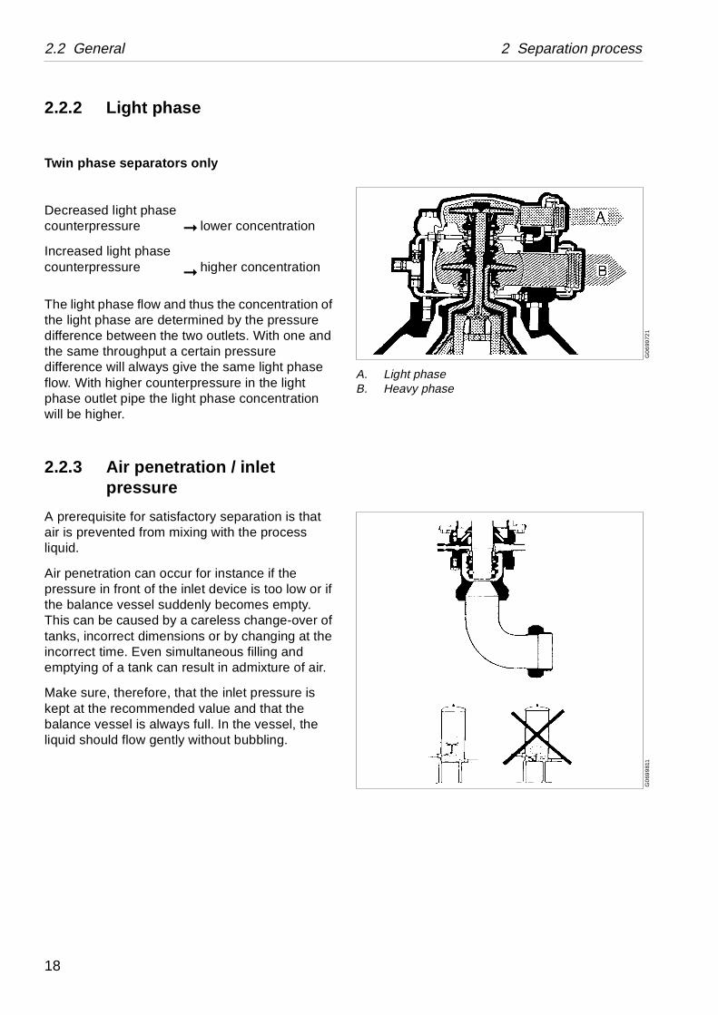
A. Light phaseB. Heavy phase
G0
699
811
2.2.2 Light phase
Twin phase separators only
The light phase flow and thus the concentration of the light phase are determined by the pressure difference between the two outlets. With one and the same throughput a certain pressure difference will always give the same light phase flow. With higher counterpressure in the light phase outlet pipe the light phase concentration will be higher.
2.2.3 Air penetration / inlet pressure
A prerequisite for satisfactory separation is that air is prevented from mixing with the process liquid.
Air penetration can occur for instance if the pressure in front of the inlet device is too low or if the balance vessel suddenly becomes empty. This can be caused by a careless change-over of tanks, incorrect dimensions or by changing at the incorrect time. Even simultaneous filling and emptying of a tank can result in admixture of air.
Make sure, therefore, that the inlet pressure is kept at the recommended value and that the balance vessel is always full. In the vessel, the liquid should flow gently without bubbling.
Decreased light phase counterpressure
Increased light phase counterpressure
➞
➞
lower concentration
higher concentration
18
3 Mechanical function
Contents
3.1 Identification and safety signson the machine 20
3.2 Power transmission 23
3.2.1 Motor and starter 25
3.3 Brake 26
3.4 Speed indication 26
3.5 Outlet / inlet(twin phase separators) 28
3.5.1 Outlet pumps 28
3.5.2 Inlet device 28
3.5.3 Axial seals 28
3.6 Outlet / inlet(single phase separators) 30
3.6.1 Outlet pump 30
3.6.2 Inlet device 30
3.6.3 Axial seals 30
3.7 Axial seals – cooling system 31
3.8 Bowl 33
19
Identification and safety signs on the machine 3 Mechanical function
example):
GV-14C
Hz)
Hz)
G06
637
51S
006
1411
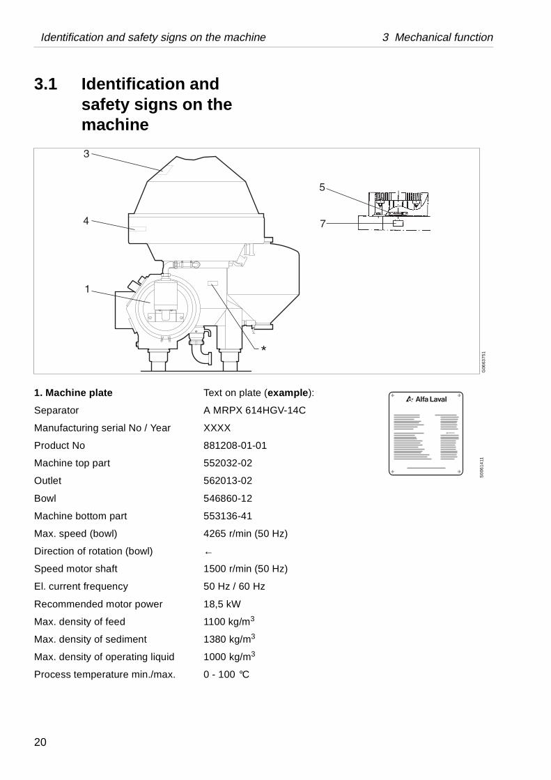
3.1 Identification and safety signs on the machine
1. Machine plate Text on plate (
Separator A MRPX 614H
Manufacturing serial No / Year XXXX
Product No 881208-01-01
Machine top part 552032-02
Outlet 562013-02
Bowl 546860-12
Machine bottom part 553136-41
Max. speed (bowl) 4265 r/min (50
Direction of rotation (bowl) ←
Speed motor shaft 1500 r/min (50
El. current frequency 50 Hz / 60 Hz
Recommended motor power 18,5 kW
Max. density of feed 1100 kg/m3
Max. density of sediment 1380 kg/m3
Max. density of operating liquid 1000 kg/m3
Process temperature min./max. 0 - 100 °C
20
3 Mechanical function Identification and safety signs on the machine
S0
061
521
S0
0632
11
50Hz
60Hz
S0
063
111
S0
1432
21
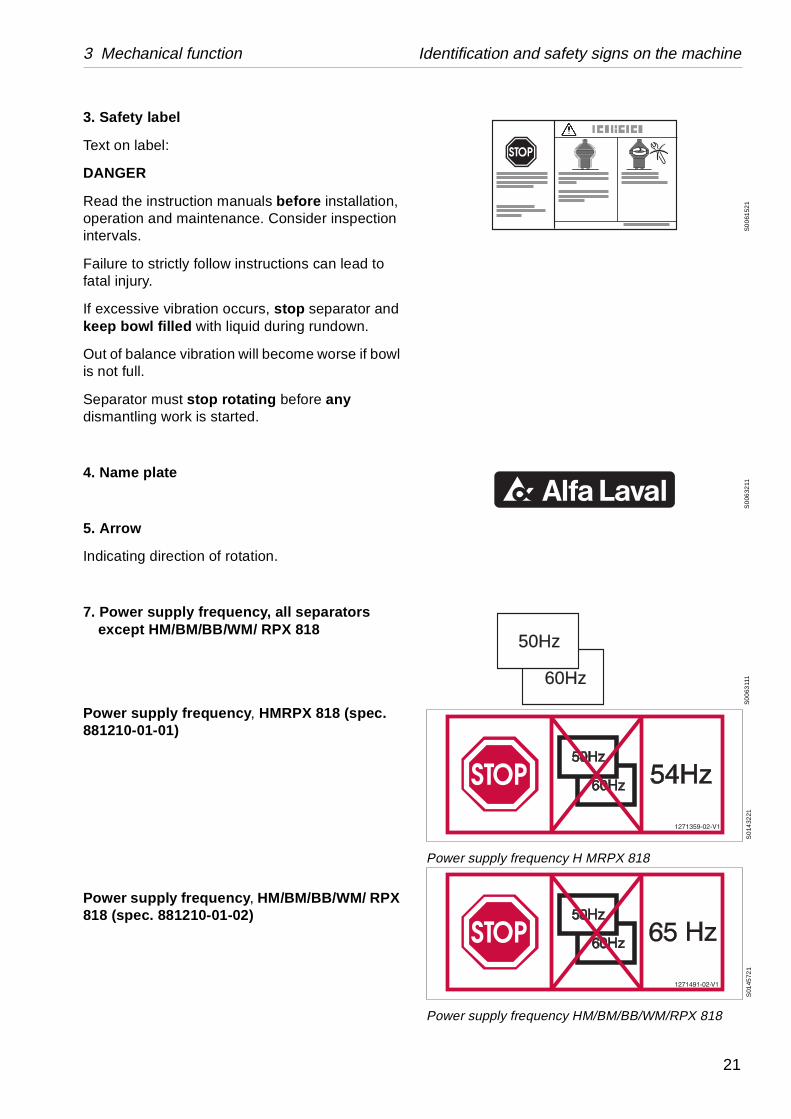
Power supply frequency H MRPX 818
S01
4572
1
Power supply frequency HM/BM/BB/WM/RPX 818
3. Safety label
Text on label:
DANGER
Read the instruction manuals before installation, operation and maintenance. Consider inspection intervals.
Failure to strictly follow instructions can lead to fatal injury.
If excessive vibration occurs, stop separator and keep bowl filled with liquid during rundown.
Out of balance vibration will become worse if bowl is not full.
Separator must stop rotating before any dismantling work is started.
4. Name plate
5. Arrow
Indicating direction of rotation.
7. Power supply frequency, all separators except HM/BM/BB/WM/ RPX 818
Power supply frequency, HMRPX 818 (spec. 881210-01-01)
Power supply frequency, HM/BM/BB/WM/ RPX 818 (spec. 881210-01-02)
21
Identification and safety signs on the machine 3 Mechanical function
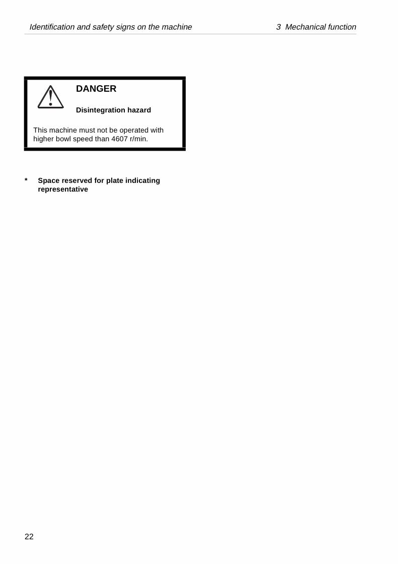
* Space reserved for plate indicating representative
DANGER
Disintegration hazard
This machine must not be operated with higher bowl speed than 4607 r/min.
22
3 Mechanical function 3.2 Power transmission
athutlet
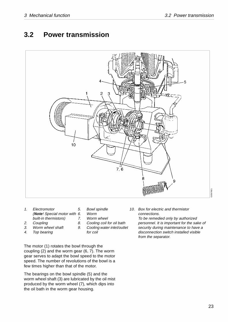
10. Box for electric and thermistor connections. To be remedied only by authorized personnel. It is important for the sake of security during maintenance to have a disconnection switch installed visible from the separator.
G05
676
E1
3.2 Power transmission
The motor (1) rotates the bowl through the coupling (2) and the worm gear (6, 7). The worm gear serves to adapt the bowl speed to the motor speed. The number of revolutions of the bowl is a few times higher than that of the motor.
The bearings on the bowl spindle (5) and the worm wheel shaft (3) are lubricated by the oil mist produced by the worm wheel (7), which dips into the oil bath in the worm gear housing.
1. Electromotor(Note! Special motor with built-in thermistors)
2. Coupling3. Worm wheel shaft4. Top bearing
5. Bowl spindle6. Worm7. Worm wheel8. Cooling coil for oil b9. Cooling water inlet/o
for coil
23
3.2 Power transmission 3 Mechanical function
The worm gear has been specially designed to operate at a low sound level.
To keep the oil temperature low, a cooling coil is installed in the worm gear housing.
The oil is cooled by the water flowing through the coil (8).
The cooling water from the coil then passes through external pipes to the axial seals.
Sealing water – see “Connection list” in Installation Manual.
Oil – see “Lubricants” in Service & Maintenance Manual.
24
3 Mechanical function 3.2 Power transmission
G0
6651
21
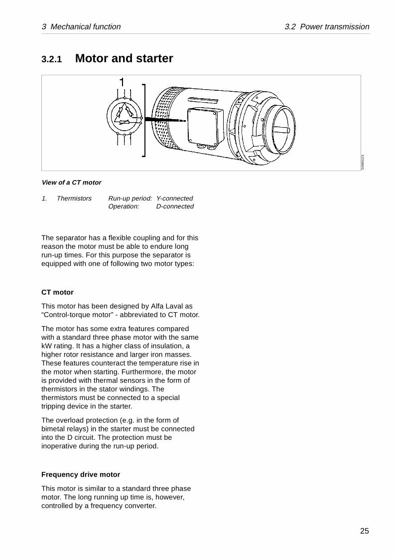
3.2.1 Motor and starter
The separator has a flexible coupling and for this reason the motor must be able to endure long run-up times. For this purpose the separator is equipped with one of following two motor types:
CT motor
This motor has been designed by Alfa Laval as “Control-torque motor” - abbreviated to CT motor.
The motor has some extra features compared with a standard three phase motor with the same kW rating. It has a higher class of insulation, a higher rotor resistance and larger iron masses. These features counteract the temperature rise in the motor when starting. Furthermore, the motor is provided with thermal sensors in the form of thermistors in the stator windings. The thermistors must be connected to a special tripping device in the starter.
The overload protection (e.g. in the form of bimetal relays) in the starter must be connected into the D circuit. The protection must be inoperative during the run-up period.
Frequency drive motor
This motor is similar to a standard three phase motor. The long running up time is, however, controlled by a frequency converter.
View of a CT motor
1. Thermistors Run-up period: Y-connectedOperation: D-connected
25
3.2 Brake 3 Mechanical function
S01
18
411
G0
6956
11
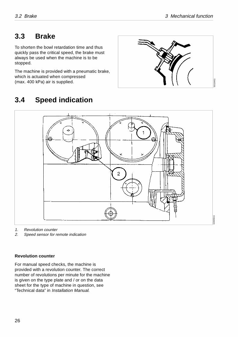
3.3 BrakeTo shorten the bowl retardation time and thus quickly pass the critical speed, the brake must always be used when the machine is to be stopped.
The machine is provided with a pneumatic brake, which is actuated when compressed (max. 400 kPa) air is supplied.
3.4 Speed indication
Revolution counter
For manual speed checks, the machine is provided with a revolution counter. The correct number of revolutions per minute for the machine is given on the type plate and / or on the data sheet for the type of machine in question, see “Technical data” in Installation Manual.
1. Revolution counter2. Speed sensor for remote indication
26
3 Mechanical function 3.2 Speed indication
Remote indication of speed (option)
In addition to the revolution counter, the separator can be provided with a device for remote indication of speed, showing the number of revolutions made by the worm wheel shaft.
Remote indication is obtained by an electronic speed instrument.
It is essential that the machine should run at the correct speed, for safety reasons as well as separation-technical.
Speed – see “Technical data” in Installation Manual.
27
3.5 Outlet / inlet (twin phase separators) 3 Mechanical function
G0
6950
21
G06
951
21
3.5 Outlet / inlet (twin phase separators)
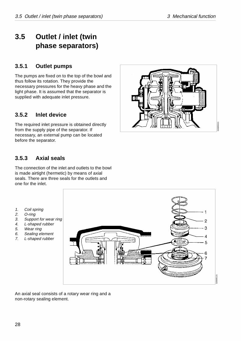
3.5.1 Outlet pumps
The pumps are fixed on to the top of the bowl and thus follow its rotation. They provide the necessary pressures for the heavy phase and the light phase. It is assumed that the separator is supplied with adequate inlet pressure.
3.5.2 Inlet device
The required inlet pressure is obtained directly from the supply pipe of the separator. If necessary, an external pump can be located before the separator.
3.5.3 Axial seals
The connection of the inlet and outlets to the bowl is made airtight (hermetic) by means of axial seals. There are three seals for the outlets and one for the inlet.
An axial seal consists of a rotary wear ring and a non-rotary sealing element.
1. Coil spring2. O-ring3. Support for wear ring4. L-shaped rubber5. Wear ring6. Sealing element7. L-shaped rubber
28
3 Mechanical function 3.5 Outlet / inlet (twin phase separators)
The sealing element and wear ring must always be flushed with liquid when the bowl rotates. The seals are therefore supplied, through special channels, with flushing water, and during the CIP-period with CIP-liquid.
29
3.6 Outlet / inlet (single phase separators) 3 Mechanical function
G06
950
11G
069
5111
3.6 Outlet / inlet (single phase separators)
3.6.1 Outlet pump
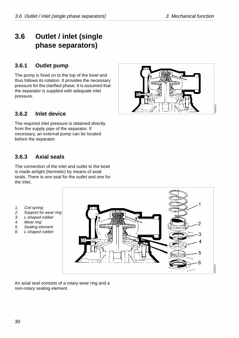
The pump is fixed on to the top of the bowl and thus follows its rotation. It provides the necessary pressure for the clarified phase. It is assumed that the separator is supplied with adequate inlet pressure.
3.6.2 Inlet device
The required inlet pressure is obtained directly from the supply pipe of the separator. If necessary, an external pump can be located before the separator.
3.6.3 Axial seals
The connection of the inlet and outlet to the bowl is made airtight (hermetic) by means of axial seals. There is one seal for the outlet and one for the inlet.
An axial seal consists of a rotary wear ring and a non-rotary sealing element.
1. Coil spring2. Support for wear ring3. L-shaped rubber4. Wear ring5. Sealing element6. L-shaped rubber
30
3 Mechanical function 3.6 Axial seals – cooling system
G0
6952
31
The sealing element and wear ring must always be flushed with liquid when the bowl rotates. The seals are therefore supplied, through special channels, with flushing water, and during the CIP-period with CIP-liquid.
3.7 Axial seals – cooling system
(The illustrations in this chapter show twin phase separators)
During starting / separation / stopping periods
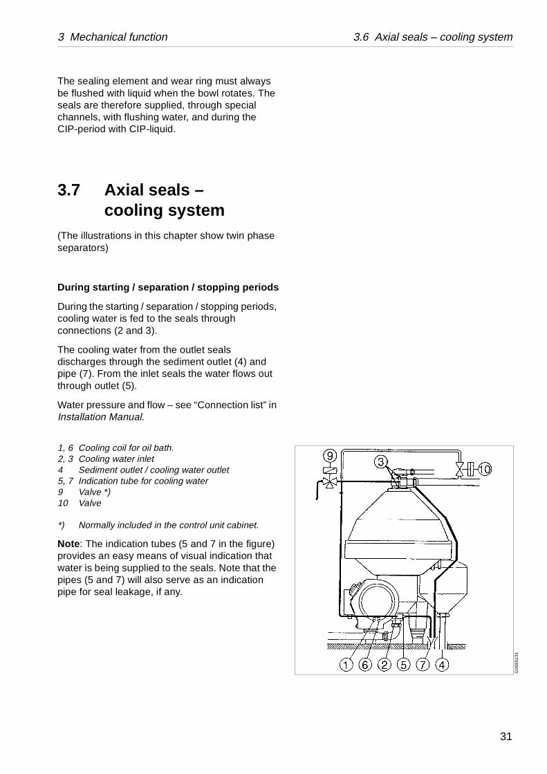
During the starting / separation / stopping periods, cooling water is fed to the seals through connections (2 and 3).
The cooling water from the outlet seals discharges through the sediment outlet (4) and pipe (7). From the inlet seals the water flows out through outlet (5).
Water pressure and flow – see “Connection list” in Installation Manual.
1, 6 Cooling coil for oil bath.2, 3 Cooling water inlet4 Sediment outlet / cooling water outlet5, 7 Indication tube for cooling water9 Valve *)10 Valve
*) Normally included in the control unit cabinet.
Note: The indication tubes (5 and 7 in the figure) provides an easy means of visual indication that water is being supplied to the seals. Note that the pipes (5 and 7) will also serve as an indication pipe for seal leakage, if any.
31
3.6 Axial seals – cooling system 3 Mechanical function
G06
9533
1G
069
543
1
During separation
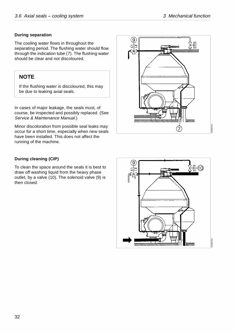
The cooling water flows in throughout the separating period. The flushing water should flow through the indication tube (7). The flushing water should be clear and not discoloured.
In cases of major leakage, the seals must, of course, be inspected and possibly replaced. (See Service & Maintenance Manual.)
Minor discoloration from possible seal leaks may occur for a short time, especially when new seals have been installed. This does not affect the running of the machine.
During cleaning (CIP)
To clean the space around the seals it is best to draw off washing liquid from the heavy phase outlet, by a valve (10). The solenoid valve (9) is then closed.
NOTE
If the flushing water is discoloured, this may be due to leaking axial seals.
32
3 Mechanical function 3.8 Bowl
G0
699
111
G06
9492
1
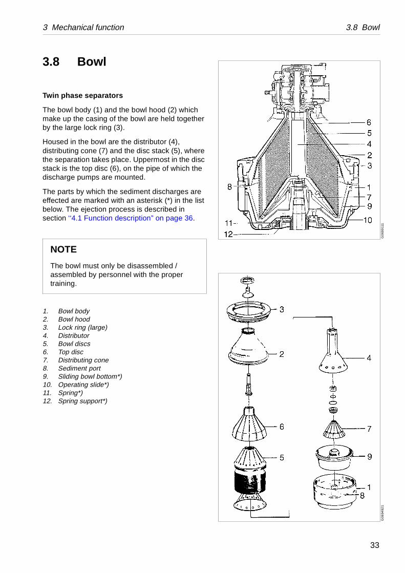
3.8 Bowl
Twin phase separators
The bowl body (1) and the bowl hood (2) which make up the casing of the bowl are held together by the large lock ring (3).
Housed in the bowl are the distributor (4), distributing cone (7) and the disc stack (5), where the separation takes place. Uppermost in the disc stack is the top disc (6), on the pipe of which the discharge pumps are mounted.
The parts by which the sediment discharges are effected are marked with an asterisk (*) in the list below. The ejection process is described in section ‘‘4.1 Function description” on page 36.
1. Bowl body2. Bowl hood3. Lock ring (large)4. Distributor5. Bowl discs6. Top disc7. Distributing cone8. Sediment port9. Sliding bowl bottom*)10. Operating slide*)11. Spring*)12. Spring support*)
NOTE
The bowl must only be disassembled / assembled by personnel with the proper training.
33
3.8 Bowl 3 Mechanical function
G06
991
21G
069
491
1
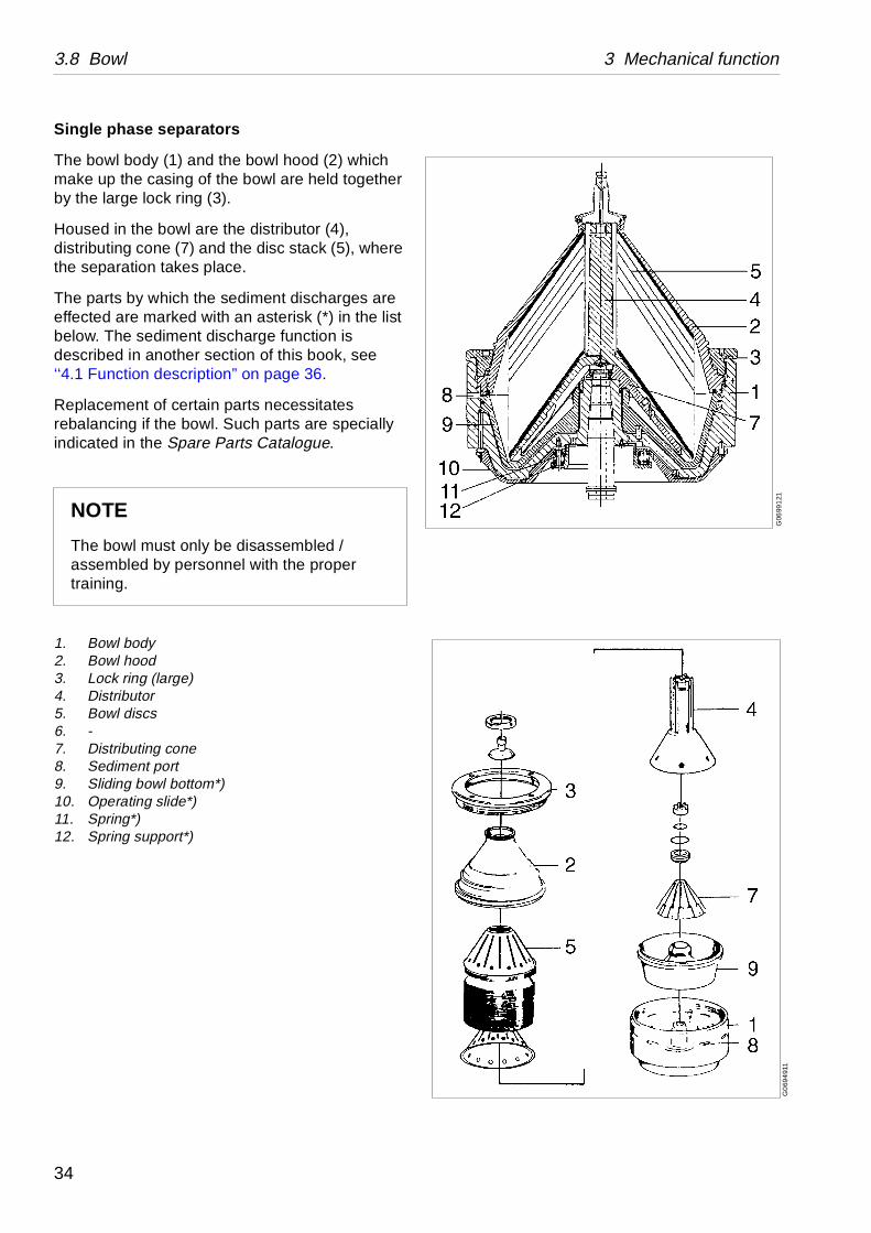
Single phase separators
The bowl body (1) and the bowl hood (2) which make up the casing of the bowl are held together by the large lock ring (3).
Housed in the bowl are the distributor (4), distributing cone (7) and the disc stack (5), where the separation takes place.
The parts by which the sediment discharges are effected are marked with an asterisk (*) in the list below. The sediment discharge function is described in another section of this book, see ‘‘4.1 Function description” on page 36.
Replacement of certain parts necessitates rebalancing if the bowl. Such parts are specially indicated in the Spare Parts Catalogue.
1. Bowl body2. Bowl hood3. Lock ring (large)4. Distributor5. Bowl discs6. -7. Distributing cone8. Sediment port9. Sliding bowl bottom*)10. Operating slide*)11. Spring*)12. Spring support*)
NOTE
The bowl must only be disassembled / assembled by personnel with the proper training.
34
4 Sediment discharge function
Contents
4.1 Function description 36
4.2 Operating water module compact (OWMC) 38
35
4.1 Function description 4 Sediment discharge function
rel
l
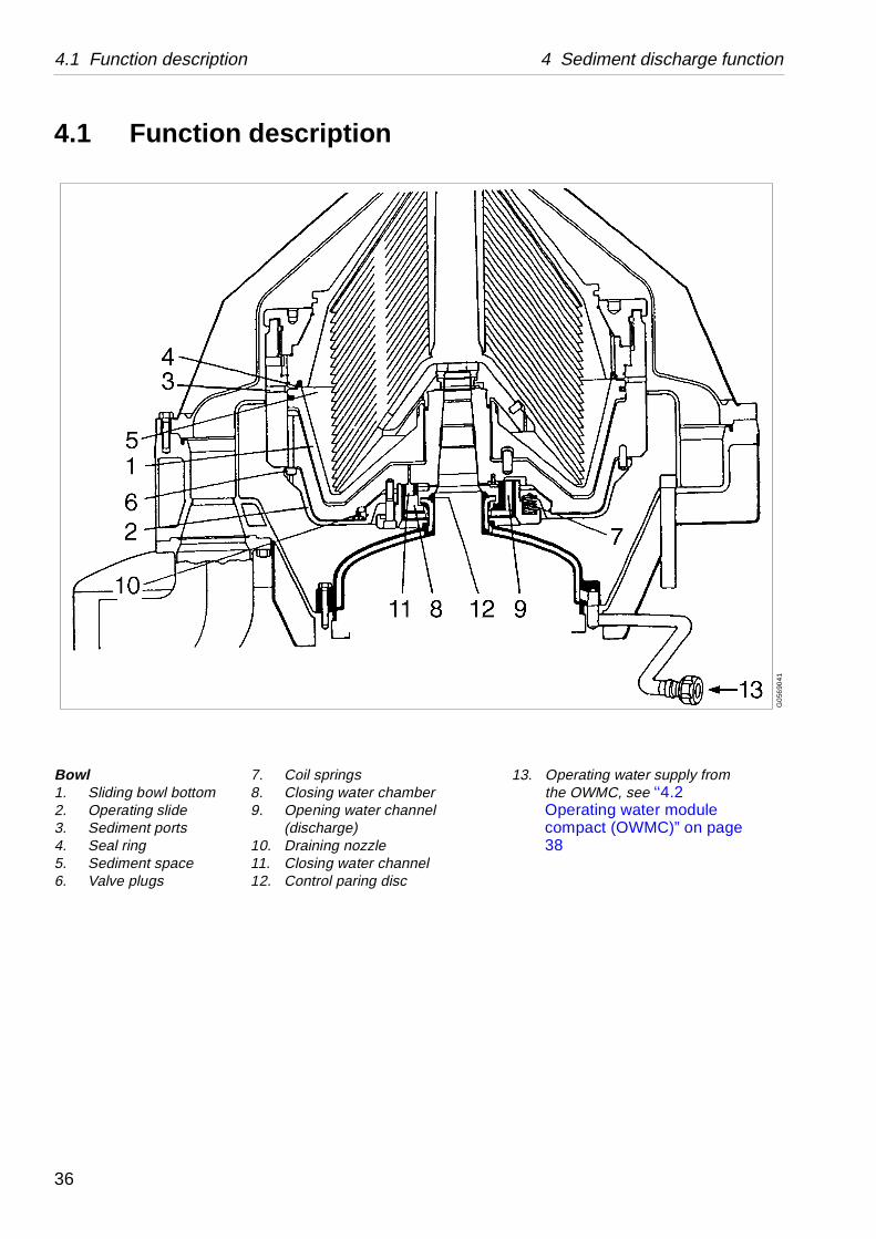
13. Operating water supply from the OWMC, see ‘‘4.2 Operating water module compact (OWMC)” on page 38
G0
5690
41
4.1 Function description
Bowl1. Sliding bowl bottom2. Operating slide3. Sediment ports4. Seal ring5. Sediment space6. Valve plugs
7. Coil springs8. Closing water chambe9. Opening water chann
(discharge)10. Draining nozzle11. Closing water channe12. Control paring disc
36
4 Sediment discharge function 4.1 Function description
ber of ports stitutes g bowl ting on otation the erating nter-ecause r
sed by slide is level is f a
forces plied in ating ) to the
sure l body sing
e is
h the slide wl supply.
hole
ston ting
rating e
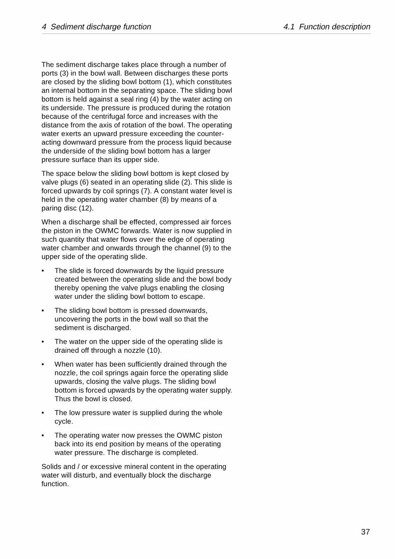
The sediment discharge takes place through a numports (3) in the bowl wall. Between discharges theseare closed by the sliding bowl bottom (1), which conan internal bottom in the separating space. The slidinbottom is held against a seal ring (4) by the water acits underside. The pressure is produced during the rbecause of the centrifugal force and increases with distance from the axis of rotation of the bowl. The opwater exerts an upward pressure exceeding the couacting downward pressure from the process liquid bthe underside of the sliding bowl bottom has a largepressure surface than its upper side.
The space below the sliding bowl bottom is kept clovalve plugs (6) seated in an operating slide (2). Thisforced upwards by coil springs (7). A constant waterheld in the operating water chamber (8) by means oparing disc (12).
When a discharge shall be effected, compressed airthe piston in the OWMC forwards. Water is now supsuch quantity that water flows over the edge of operwater chamber and onwards through the channel (9upper side of the operating slide.
• The slide is forced downwards by the liquid prescreated between the operating slide and the bowthereby opening the valve plugs enabling the clowater under the sliding bowl bottom to escape.
• The sliding bowl bottom is pressed downwards,uncovering the ports in the bowl wall so that thesediment is discharged.
• The water on the upper side of the operating sliddrained off through a nozzle (10).
• When water has been sufficiently drained througnozzle, the coil springs again force the operatingupwards, closing the valve plugs. The sliding bobottom is forced upwards by the operating waterThus the bowl is closed.
• The low pressure water is supplied during the wcycle.
• The operating water now presses the OWMC piback into its end position by means of the operawater pressure. The discharge is completed.
Solids and / or excessive mineral content in the opewater will disturb, and eventually block the dischargfunction.
37
4.2 Operating water module compact (OWMC) 4 Sediment discharge function
G08
779
21
4.2 Operating water module compact (OWMC)
Purpose
The separator bowl can be emptied from solids by two different sediment discharge volumes determined by the duration of the increased operating liquid flow from the Operating Water Module Compact (OWMC), i.e. the time the bowl is being open. The two discharge volumes may be regarded as small and large respectively.
Design
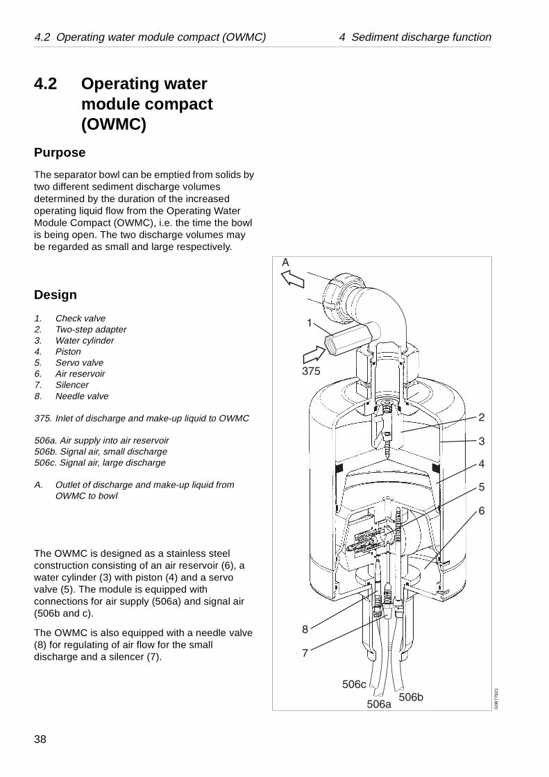
1. Check valve2. Two-step adapter3. Water cylinder4. Piston5. Servo valve6. Air reservoir7. Silencer8. Needle valve
375. Inlet of discharge and make-up liquid to OWMC
506a. Air supply into air reservoir506b. Signal air, small discharge506c. Signal air, large discharge
A. Outlet of discharge and make-up liquid from OWMC to bowl
The OWMC is designed as a stainless steel construction consisting of an air reservoir (6), a water cylinder (3) with piston (4) and a servo valve (5). The module is equipped with connections for air supply (506a) and signal air (506b and c).
The OWMC is also equipped with a needle valve (8) for regulating of air flow for the small discharge and a silencer (7).
38
4 Sediment discharge function 4.2 Operating water module compact (OWMC)
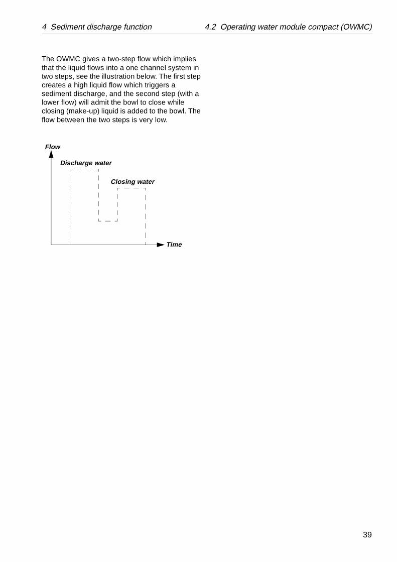
The OWMC gives a two-step flow which implies that the liquid flows into a one channel system in two steps, see the illustration below. The first step creates a high liquid flow which triggers a sediment discharge, and the second step (with a lower flow) will admit the bowl to close while closing (make-up) liquid is added to the bowl. The flow between the two steps is very low.
Flow
Discharge water
Time
Closing water
39
4.2 Operating water module compact (OWMC) 4 Sediment discharge function
G0
878
411
Settings
Start to set the large discharge volume.
Proceed in following way:
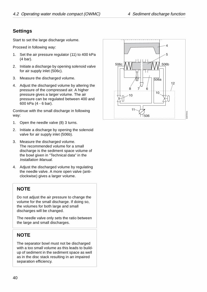
1. Set the air pressure regulator (11) to 400 kPa (4 bar).
2. Initiate a discharge by opening solenoid valve for air supply inlet (506c).
3. Measure the discharged volume.
4. Adjust the discharged volume by altering the pressure of the compressed air. A higher pressure gives a larger volume. The air pressure can be regulated between 400 and 600 kPa (4 - 6 bar).
Continue with the small discharge in following way:
1. Open the needle valve (8) 3 turns.
2. Initiate a discharge by opening the solenoid valve for air supply inlet (506b).
3. Measure the discharged volume.The recommended volume for a small discharge is the sediment space volume of the bowl given in “Technical data” in the Installation Manual.
4. Adjust the discharged volume by regulating the needle valve. A more open valve (anti-clockwise) gives a larger volume.
NOTE
Do not adjust the air pressure to change the volume for the small discharge. If doing so, the volumes for both large and small discharges will be changed.
The needle valve only sets the ratio between the large and small discharges.
NOTE
The separator bowl must not be discharged with a too small volume as this leads to build-up of sediment in the sediment space as well as in the disc stack resulting in an impaired separation efficiency.
40
5 Installation and first start
Contents
5.1 Preparations 42
5.2 Before first start 43
5.3 First start 44
5.4 Operation 44
5.4.1 Ejection process 45
5.4.2 Cleaning 45
5.4.3 Separation 46
5.4.4 Operation 46
5.5 Stopping 46
41
5.1 Preparations 5 Installation and first start
G06
659
11
5.1 Preparations1. Set up the machine (without the bowl)
according to the installation instructions.
2. Flush the piping thoroughly to remove any residues such as chips, welding beads, etc.
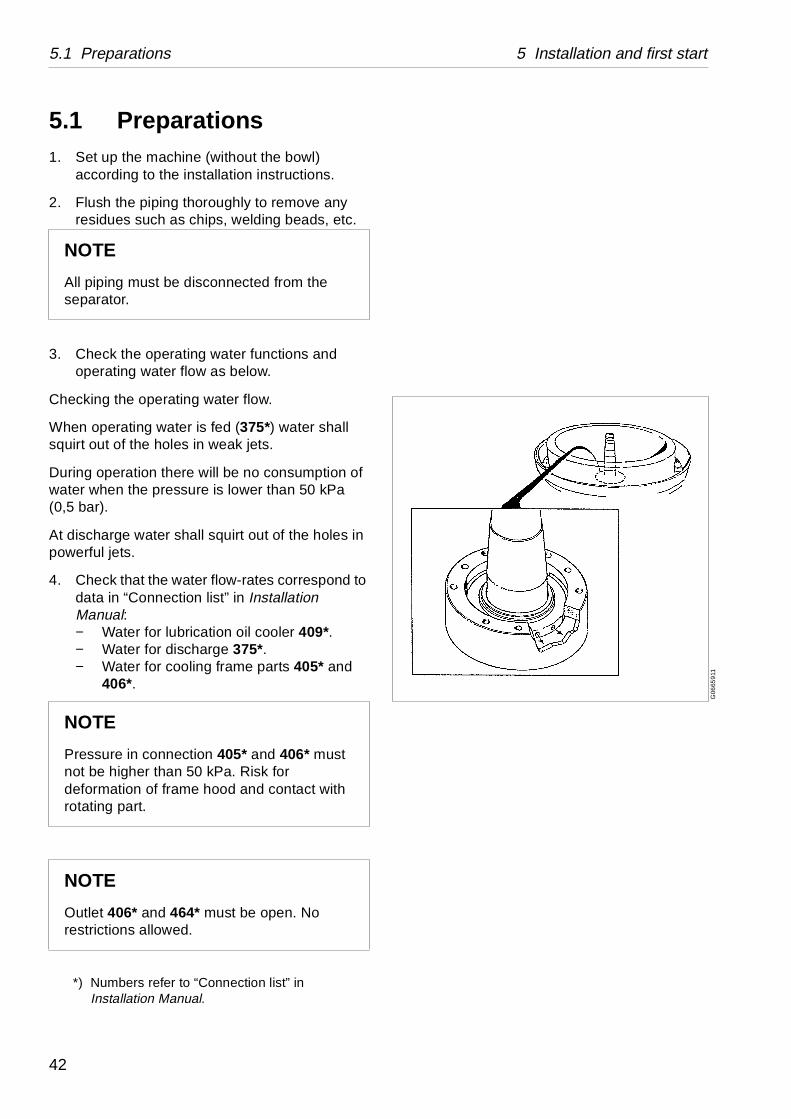
3. Check the operating water functions and operating water flow as below.
Checking the operating water flow.
When operating water is fed (375*) water shall squirt out of the holes in weak jets.
During operation there will be no consumption of water when the pressure is lower than 50 kPa (0,5 bar).
At discharge water shall squirt out of the holes in powerful jets.
4. Check that the water flow-rates correspond to data in “Connection list” in Installation Manual:− Water for lubrication oil cooler 409*.− Water for discharge 375*.− Water for cooling frame parts 405* and
406*.
*) Numbers refer to “Connection list” in Installation Manual.
NOTE
All piping must be disconnected from the separator.
NOTE
Pressure in connection 405* and 406* must not be higher than 50 kPa. Risk for deformation of frame hood and contact with rotating part.
NOTE
Outlet 406* and 464* must be open. No restrictions allowed.
42
5 Installation and first start 5.1 Before first start
S01
178
11S
011
791
1S
011
802
1S
011
8111
G0
6992
21
5.2 Before first start• Pour about 13 litres lubricating oil of correct
grade into the worm gear housing – see “Lubricants” in Installation Manual.
• Check the oil (approx. half way up the sight glass). Be aware of that a very small quantity of oil may remain at the bottom edge of the sight glass even when the gear housing is emptied for oil.
• Assemble the bowl and the inlet and outlet parts as described in the Service & Maintenance Manual.
• Make sure that the frame hood bolts have been tightened.
• Make sure that the bolts for centring ring and outlets have been tightened to the correct torque. See Service & Maintenance Manual.
• Make sure that the bolts for the inlet device have been tightened.
• Check that water and air are being supplied to the control panel.
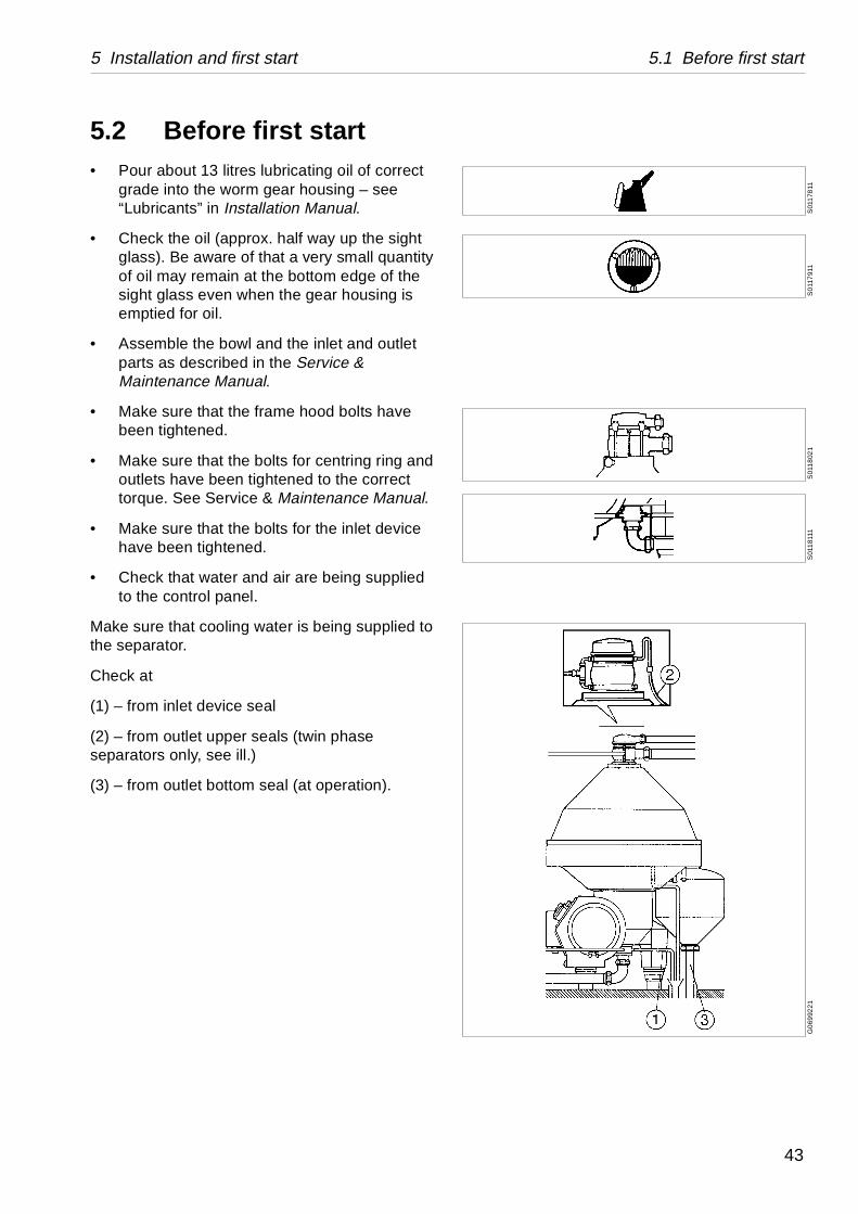
Make sure that cooling water is being supplied to the separator.
Check at
(1) – from inlet device seal
(2) – from outlet upper seals (twin phase separators only, see ill.)
(3) – from outlet bottom seal (at operation).
43
5.3 First start 5 Installation and first start
S0
1182
11
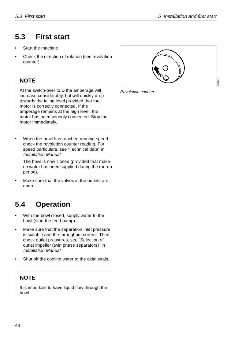
Revolution counter
5.3 First start• Start the machine
• Check the direction of rotation (see revolution counter).
• When the bowl has reached running speed, check the revolution counter reading. For speed particulars, see “Technical data” in Installation Manual.
The bowl is now closed (provided that make-up water has been supplied during the run-up period).
• Make sure that the valves in the outlets are open.
5.4 Operation• With the bowl closed, supply water to the
bowl (start the feed pump).
• Make sure that the separation inlet pressure is suitable and the throughput correct. Then check outlet pressures, see “Selection of outlet impeller (twin phase separators)” in Installation Manual.
• Shut off the cooling water to the axial seals.
NOTE
At the switch-over to D the amperage will increase considerably, but will quickly drop towards the idling level provided that the motor is correctly connected. If the amperage remains at the high level, the motor has been wrongly connected. Stop the motor immediately.
NOTE
It is important to have liquid flow through the bowl.
44
5 Installation and first start 5.3 Operation
S0
118
311
• Check that the bowl is tightly closed – no water in the cyclone outlet.
• Disconnect the pipes for cooling water to the outlet seals. Check for possible leakage from these. Major leaks must not occur. Minor leaks may temporarily be left uncorrected. Some seals need as a rule certain wear-in period.
• Connect the pipes for cooling water.
• Open the cooling water supply again.
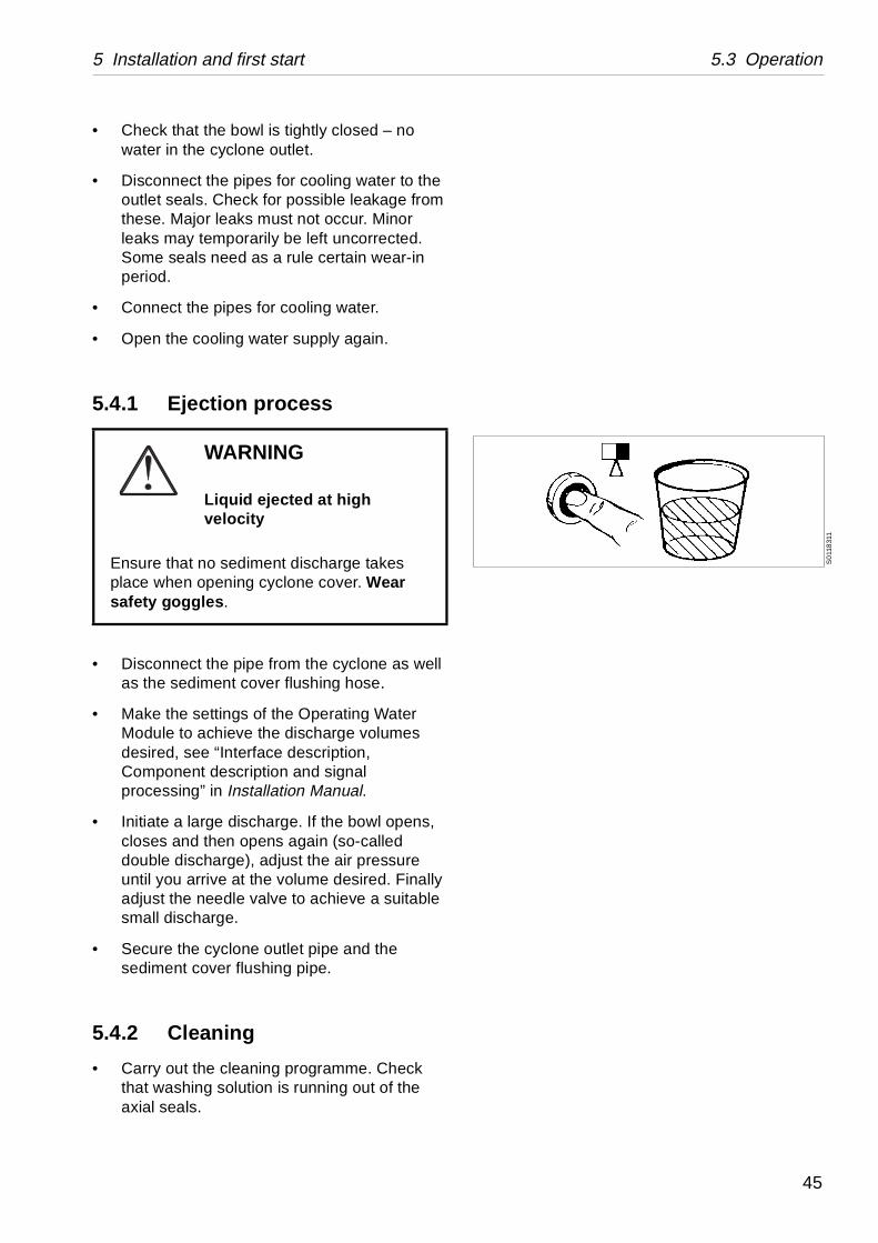
5.4.1 Ejection process
• Disconnect the pipe from the cyclone as well as the sediment cover flushing hose.
• Make the settings of the Operating Water Module to achieve the discharge volumes desired, see “Interface description, Component description and signal processing” in Installation Manual.
• Initiate a large discharge. If the bowl opens, closes and then opens again (so-called double discharge), adjust the air pressure until you arrive at the volume desired. Finally adjust the needle valve to achieve a suitable small discharge.
• Secure the cyclone outlet pipe and the sediment cover flushing pipe.
5.4.2 Cleaning
• Carry out the cleaning programme. Check that washing solution is running out of the axial seals.
WARNING
Liquid ejected at high velocity
Ensure that no sediment discharge takes place when opening cyclone cover. Wear safety goggles.
45
5.3 Stopping 5 Installation and first start
S01
184
11
5.4.3 Separation
• Supply process liquid.
• Check the inlet pressure, see “Selection of outlet impeller (twin phase separators)” in Installation Manual.
• Adjust the outlet pressures, see “Selection of outlet impeller (twin phase separators)” in Installation Manual.
5.4.4 Operation
• Check the throughput. Make a final adjustment of inlet and outlet pressures.
• Make sure that no air is being sucked into the feed pipe via e.g.a balance vessel, if fitted. This should always be kept filled. The process liquid should flow evenly in the vessel without bubbling.
After separation is completed, carry out the cleaning programme. Dismantle the bowl and check the cleaning 3 – 4 days after the first operation with product.
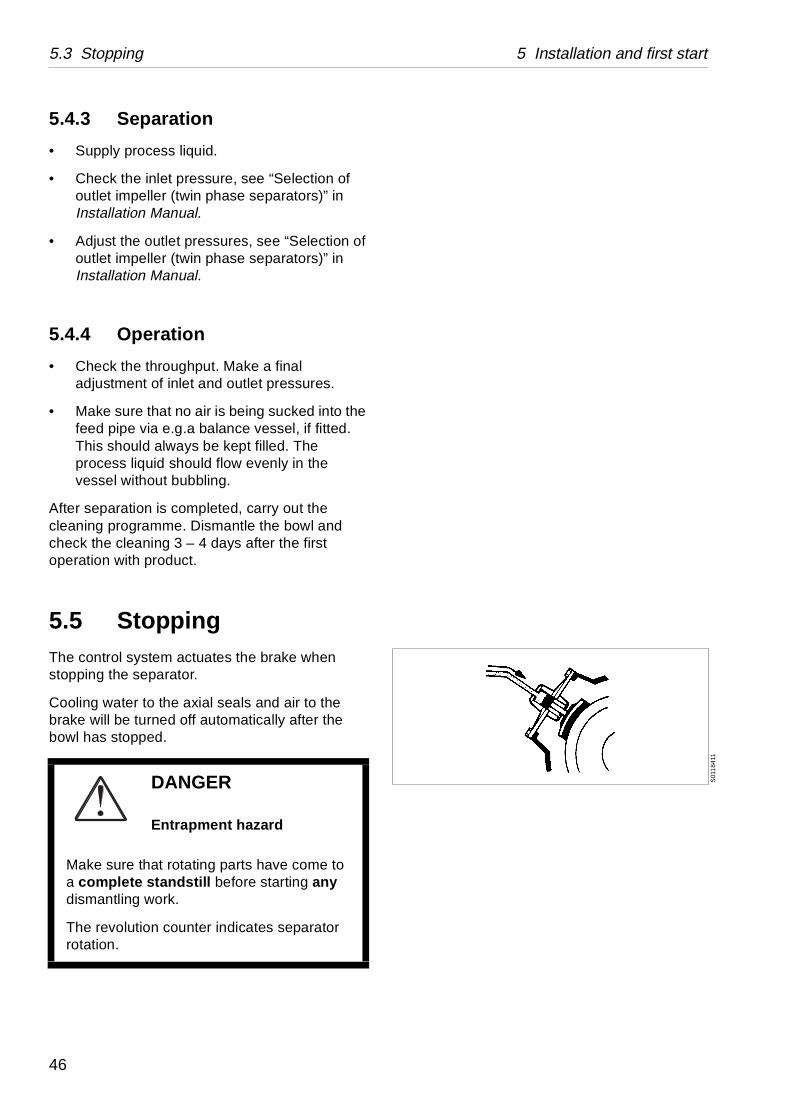
5.5 StoppingThe control system actuates the brake when stopping the separator.
Cooling water to the axial seals and air to the brake will be turned off automatically after the bowl has stopped.
DANGER
Entrapment hazard
Make sure that rotating parts have come to a complete standstill before starting any dismantling work.
The revolution counter indicates separator rotation.
46
6 Cleaning
Contents
6.1 Check of cleaning 48
6.1.1 Disc pressure 49
47
6.1 Check of cleaning 6 Cleaning
G06
958
11
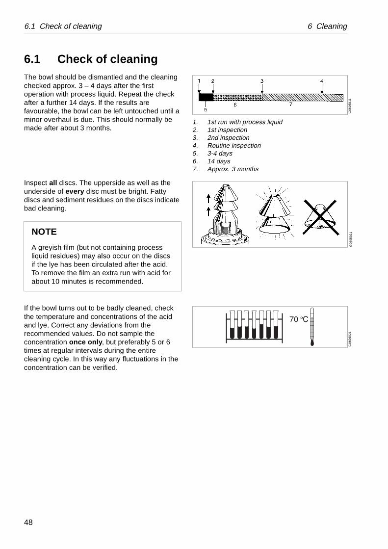
1. 1st run with process liquid2. 1st inspection3. 2nd inspection4. Routine inspection5. 3-4 days6. 14 days7. Approx. 3 months
G06
9592
1G
069
6021
6.1 Check of cleaningThe bowl should be dismantled and the cleaning checked approx. 3 – 4 days after the first operation with process liquid. Repeat the check after a further 14 days. If the results are favourable, the bowl can be left untouched until a minor overhaul is due. This should normally be made after about 3 months.
Inspect all discs. The upperside as well as the underside of every disc must be bright. Fatty discs and sediment residues on the discs indicate bad cleaning.
If the bowl turns out to be badly cleaned, check the temperature and concentrations of the acid and lye. Correct any deviations from the recommended values. Do not sample the concentration once only, but preferably 5 or 6 times at regular intervals during the entire cleaning cycle. In this way any fluctuations in the concentration can be verified.
NOTE
A greyish film (but not containing process liquid residues) may also occur on the discs if the lye has been circulated after the acid. To remove the film an extra run with acid for about 10 minutes is recommended.
48
6 Cleaning 6.1 Check of cleaning
6.1.1 Disc pressure
In a tightened bowl the disc pressure may in time decrease so that the individual discs are not stable, although the guide mark on the lock ring is directly aligned to the corresponding mark on the bowl hood. Bad bowl running (vibration) may be the result. If so, one or more extra discs must be added to the disc stack. Extra discs must be located under the thick-caulked discs. See description in the Service & Maintenance Manual.
NOTE
Insufficient compression of the disc stack can affect the bowl balance, causing abnormal vibration of the machine.
49
6.1 Check of cleaning 6 Cleaning
50
7 Operating routine
Contents
7.1 Check points 52
7.1.1 Before start 52
7.1.2 Start and run-up 52
7.1.3 Separation 53
7.1.4 Cleaning 53
7.1.5 Stop 54
51
7.1 Check points 7 Operating routine
G0
764
811
S01
18
021
S0
118
111
S0
117
911
OFF STARTON
S0
1211
11S
011
8211
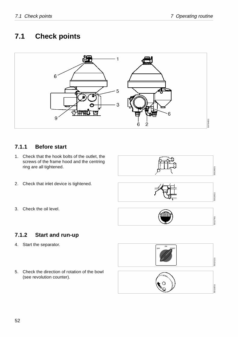
7.1 Check points
7.1.1 Before start
1. Check that the hook bolts of the outlet, the screws of the frame hood and the centring ring are all tightened.
2. Check that inlet device is tightened.
3. Check the oil level.
7.1.2 Start and run-up
4. Start the separator.
5. Check the direction of rotation of the bowl (see revolution counter).
52
7 Operating routine 7.1 Check points
S01
2091
1S
00
5561
1S
012
1011
S01
2101
1
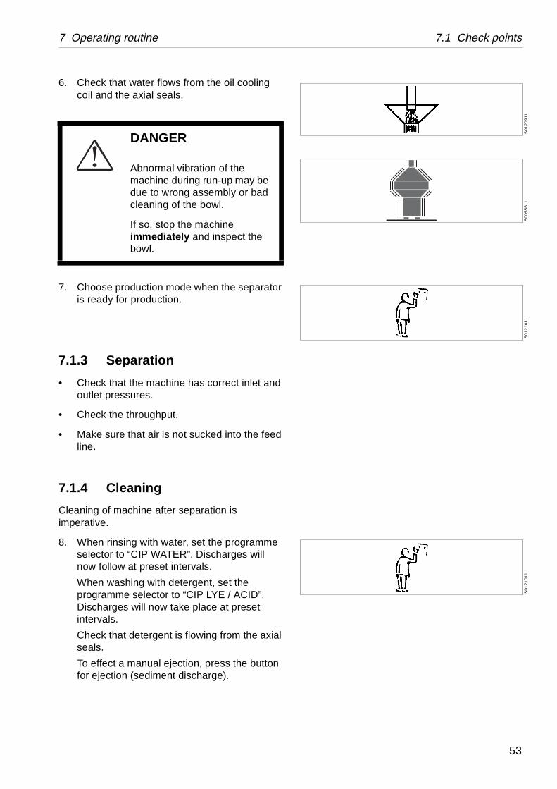
6. Check that water flows from the oil cooling coil and the axial seals.
7. Choose production mode when the separator is ready for production.
7.1.3 Separation
• Check that the machine has correct inlet and outlet pressures.
• Check the throughput.
• Make sure that air is not sucked into the feed line.
7.1.4 Cleaning
Cleaning of machine after separation is imperative.
8. When rinsing with water, set the programme selector to “CIP WATER”. Discharges will now follow at preset intervals.
When washing with detergent, set the programme selector to “CIP LYE / ACID”. Discharges will now take place at preset intervals.
Check that detergent is flowing from the axial seals.
To effect a manual ejection, press the button for ejection (sediment discharge).
DANGER
Abnormal vibration of the machine during run-up may be due to wrong assembly or bad cleaning of the bowl.
If so, stop the machine immediately and inspect the bowl.
53
7.1 Check points 7 Operating routine
S0
0501
11G
024
6241
7.1.5 Stop
Do not stop separator uncleaned, since it will lead to that manually cleaning has to be done before start up.
The bowl must be closed and filled with liquid during the run down period. Water is fed to the axial seals automatically until the bowl has stopped.
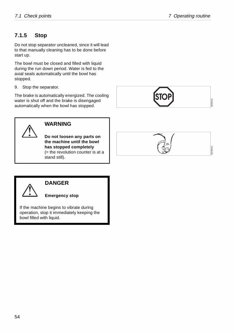
9. Stop the separator.
The brake is automatically energized. The cooling water is shut off and the brake is disengaged automatically when the bowl has stopped.
WARNING
Do not loosen any parts on the machine until the bowl has stopped completely(= the revolution counter is at a stand still).
DANGER
Emergency stop
If the machine begins to vibrate during operation, stop it immediately keeping the bowl filled with liquid.
54
8 Trouble tracing
Contents
8.1 Mechanical function 56
8.2 Sediment discharge function 59
8.2.1 OWMC related faults 60
8.3 Axial seals 61
55
8.1 Mechanical function 8 Trouble tracing
Remedy
ure. Fuses in e blown or
Find the fault. Change or reset fuse
ot operating Check. Remedy
ripped before Motor too hot. See below
d Check the air pressure to brake
otor defect Change or repair motor
rips due to motor
Remove motor hood. Allow motor to cool down (at least 3 hours – if no extra fan cooling)
as not m star to
Check setting of relay
too early Check. Remedy
o low Check. Remedy
Check. Remedy
as switched elta too soon
Check relay setting
wer supply Check. Remedy
Check. Remedy
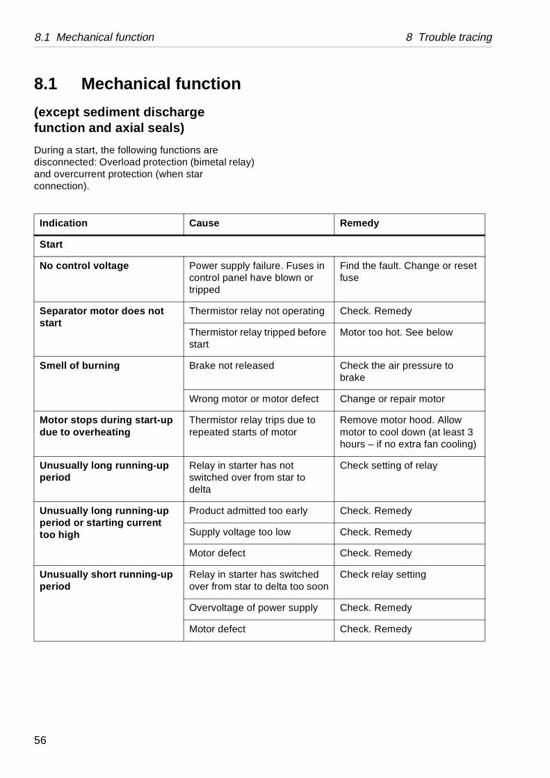
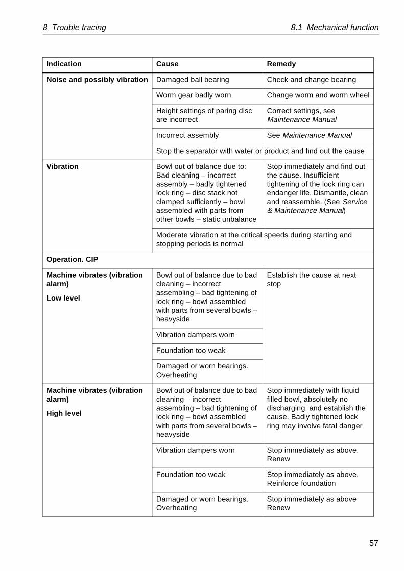
8.1 Mechanical function
(except sediment discharge function and axial seals)
During a start, the following functions are disconnected: Overload protection (bimetal relay) and overcurrent protection (when star connection).
Indication Cause
Start
No control voltage Power supply failcontrol panel havtripped
Separator motor does not start
Thermistor relay n
Thermistor relay tstart
Smell of burning Brake not release
Wrong motor or m
Motor stops during start-up due to overheating
Thermistor relay trepeated starts of
Unusually long running-up period
Relay in starter hswitched over frodelta
Unusually long running-up period or starting current too high
Product admitted
Supply voltage to
Motor defect
Unusually short running-up period
Relay in starter hover from star to d
Overvoltage of po
Motor defect
56
8 Trouble tracing 8.1 Mechanical function
aring Check and change bearing
worn Change worm and worm wheel
paring disc Correct settings, see Maintenance Manual
ly See Maintenance Manual
r with water or product and find out the cause
ce due to: correct tightened ack not tly – bowl arts from tic unbalance
Stop immediately and find out the cause. Insufficient tightening of the lock ring can endanger life. Dismantle, clean and reassemble. (See Service & Maintenance Manual)
n at the critical speeds during starting and is normal
ce due to bad ct tightening of ssembled veral bowls –
Establish the cause at next stop
s worn
eak
bearings.
ce due to bad ct tightening of ssembled veral bowls –
Stop immediately with liquid filled bowl, absolutely no discharging, and establish the cause. Badly tightened lock ring may involve fatal danger
s worn Stop immediately as above. Renew
eak Stop immediately as above. Reinforce foundation
bearings. Stop immediately as aboveRenew
Remedy
Noise and possibly vibration Damaged ball be
Worm gear badly
Height settings ofare incorrect
Incorrect assemb
Stop the separato
Vibration Bowl out of balanBad cleaning – inassembly – badlylock ring – disc stclamped sufficienassembled with pother bowls – sta
Moderate vibratiostopping periods
Operation. CIP
Machine vibrates (vibration alarm)
Low level
Bowl out of balancleaning – incorreassembling – badlock ring – bowl awith parts from seheavyside
Vibration damper
Foundation too w
Damaged or wornOverheating
Machine vibrates (vibration alarm)
High level
Bowl out of balancleaning – incorreassembling – badlock ring – bowl awith parts from seheavyside
Vibration damper
Foundation too w
Damaged or wornOverheating
Indication Cause
57
8.1 Mechanical function 8 Trouble tracing
bearings. Stop immediately as aboveRenew
Remedy
uency too Check. Remedy
Check. Remedy
ower supply Check and remedy the fault
rloading of ng
See ‘‘8.2 Sediment discharge function” on page 59
oling coil Change or repair the coil
brake is too Check. Remedy
See ‘‘8.2 Sediment discharge function” on page 59
Check. Remedy
evice Check. Remedy
e lining Change or clean
brake is too ot turned on
Check. Remedy
n at the critical speeds during starting and l
Remedy
,
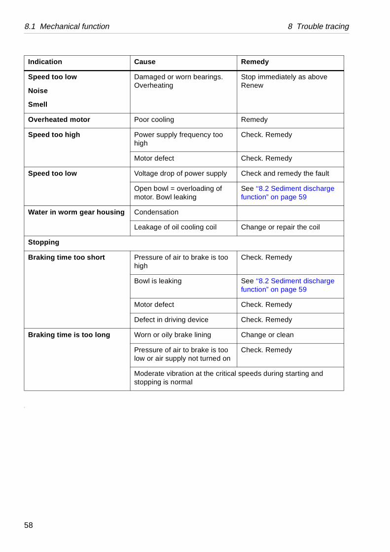
Speed too low
Noise
Smell
Damaged or wornOverheating
Overheated motor Poor cooling
Speed too high Power supply freqhigh
Motor defect
Speed too low Voltage drop of p
Open bowl = ovemotor. Bowl leaki
Water in worm gear housing Condensation
Leakage of oil co
Stopping
Braking time too short Pressure of air tohigh
Bowl is leaking
Motor defect
Defect in driving d
Braking time is too long Worn or oily brak
Pressure of air tolow or air supply n
Moderate vibratiostopping is norma
Indication Cause
58
8 Trouble tracing 8.2 Sediment discharge function
Remedy
ing between e separator
Purge the system for air
eakage gs in seal ring in m
Change the seals
tween ng (≥ 1 h) the ism may
Discharge twice in order to reset the system to normal volume
g pressure ent
Correct
perating pressure valve is
Check the water supply. Adjust the pressure to maximum value (approx. 70 kPa) but avoid leakage (max 50 l/h)
n operating Change the valve plugs
e sliding s
Change the seal ring
he sliding Clean
wl nave Remedy according to instructions for maintenance
bowl hood Change the seal ring
leakage of creases due f operating
Run the separator with constant operating water pressure
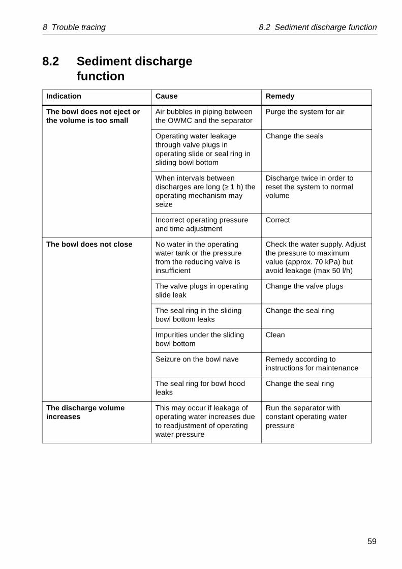
8.2 Sediment discharge function
Indication Cause
The bowl does not eject or the volume is too small
Air bubbles in pipthe OWMC and th
Operating water lthrough valve pluoperating slide orsliding bowl botto
When intervals bedischarges are looperating mechanseize
Incorrect operatinand time adjustm
The bowl does not close No water in the owater tank or the from the reducinginsufficient
The valve plugs islide leak
The seal ring in thbowl bottom leak
Impurities under tbowl bottom
Seizure on the bo
The seal ring for leaks
The discharge volume increases
This may occur ifoperating water into readjustment owater pressure
59

8.2 Sediment discharge function 8 Trouble tracing
Corrective actions Page
ing of rottled
Adjust the throttling 40
ng of o low
Adjust the air pressure 40
ir to Check the air supply –
line let
Check function of the valve –
r air n
Follow the instructions carefully for air and water quality.
1)
Clean and lubricate piston and cylinder with GLEITMO 1821V
2)
ter line
Check the operating water pressure
3)
in the Renew the silencer –
line let
Check function of the valve –
two- Renew the sealing 2)pos. 8
the air Reduce the air pressure 40
in the Clean the nozzle 2)
8.2.1 OWMC related faults
1) See Installation Manual
2) See “Operating water module (OWMC)” in Service & Maintenance Manual
3) See Installation Manual, “Connection list”, connection 375
Indication Cause
The bowl does not eject or the volume is too small
Needle valve for settsmall discharge is thtoo much
Air pressure for settilarge discharge is to
No supply or signal athe OWMC
Faulty check valve inoperating water feedbefore the OWMC in
OWMC piston does not return to its initial position or returns too slowly
Impurities in water owhich increase frictiobetween piston and cylinder
Too low operating wapressure in the feed before the OWMC
Silencer for air outletOWMC is clogged
Faulty check valve inoperating water feedbefore the OWMC in
The discharged volume too large
Faulty sealing for thepulse adapter
Too high pressure ofsupply (506a).
Bowl fails to close after sediment discharge
Clogged nozzle fittedtwo-pulse adapter
60
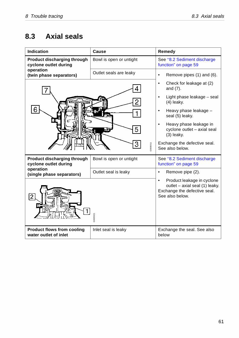
8 Trouble tracing 8.3 Axial seals
Remedy
ntight See ‘‘8.2 Sediment discharge function” on page 59
eaky • Remove pipes (1) and (6).
• Check for leakage at (2) and (7).
• Light phase leakage – seal (4) leaky.
• Heavy phase leakage – seal (5) leaky.
• Heavy phase leakage in cyclone outlet – axial seal (3) leaky.
Exchange the defective seal. See also below.
ntight See ‘‘8.2 Sediment discharge function” on page 59
ky • Remove pipe (2).
• Product leakage in cyclone outlet – axial seal (1) leaky.
Exchange the defective seal. See also below.
Exchange the seal. See also below
G06
993
11
8.3 Axial seals
Indication Cause
Product discharging through cyclone outlet during operation(twin phase separators)
Bowl is open or u
Outlet seals are l
Product discharging through cyclone outlet during operation(single phase separators)
Bowl is open or u
Outlet seal is lea
Product flows from cooling water outlet of inlet
Inlet seal is leaky
G0
699
321
61
8.3 Axial seals 8 Trouble tracing
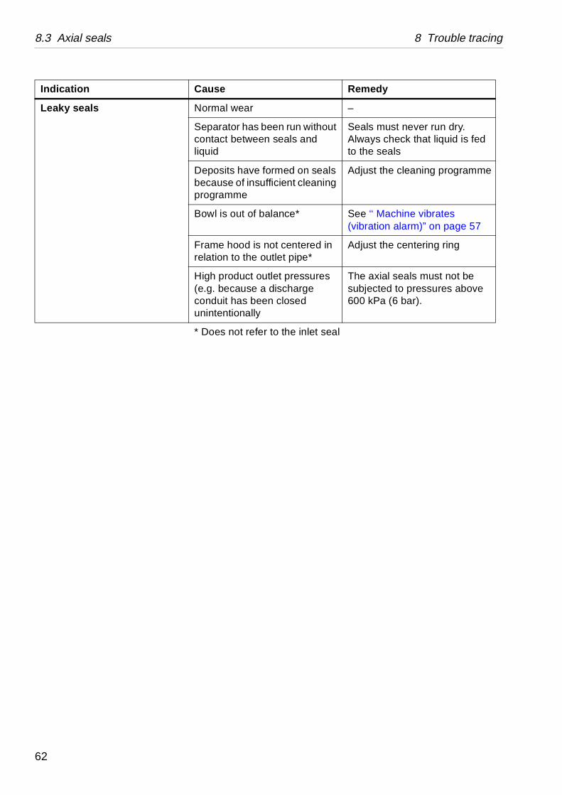
Remedy
–
en run without seals and
Seals must never run dry. Always check that liquid is fed to the seals
med on seals cient cleaning
Adjust the cleaning programme
ance* See ‘‘ Machine vibrates (vibration alarm)” on page 57
t centered in tlet pipe*
Adjust the centering ring
et pressures ischarge closed
The axial seals must not be subjected to pressures above 600 kPa (6 bar).
o the inlet seal
Indication Cause
Leaky seals Normal wear
Separator has becontact between liquid
Deposits have forbecause of insuffiprogramme
Bowl is out of bal
Frame hood is norelation to the ou
High product outl(e.g. because a dconduit has beenunintentionally
* Does not refer t
62