Embed Size (px)
Citation preview

WARNING: Do not assemble, install, or operate this equipment without reading ALL of this manual
and the safety precautions and warnings illustrated in this manual.
OPERATOR’S MANUAL
Model PL-40
Plasma Cutter
KDAR Company Tel: (636) 493-9920
3671 New Town Blvd Fax: (636) 493-9921
St. Charles, MO 63301 Web Site: www.hotmaxtorches.com

OPERATOR’S MANUAL
Model PL-40
Plasma Cutter
TABLE OF CONTENTS
Safety Symbols & Precautions 1
Specifications 4
Package Contents 4
Installation and Setup 5
Operation—Safety 7
Operation—Controls 8
Operation—Design Features 9
Operation—Job Setup and Control Settings 10
Operation—Cutting 11
Maintenance 12
Maintenance—Replacing Consumables 13
KDAR Company

KDAR Company
SAFETY PRECAUTIONS AND WARNINGS
PLEASE READ BEFORE USING EQUIPMENT
Keep children away from this equipment
Protect your self and others from possible injury
Pacemaker wearers should consult with their doctor before operating
Read and follow all instructions in this manual before operating
All installation, operation, and maintenance procedures should be per-
formed only by qualified individuals
ELECTRIC SHOCK CAN KILL. Plasma cutting uses more voltage than welding, as high as 200 to 400 volts DC when output is oper-
ating.
The input circuits are also live and hot when the power is on
Do not touch live electrical parts
Wear dry, hole free insulated work gloves and body protection when operating
Do not touch torch components if in contact with the work piece or ground
Always turn off power before cleaning, checking, or changing parts
Properly ground this piece of equipment per state and federal requirements
Inspect and replace any worn or damaged torch cables or leads
Keep all panels and covers securely in place
Keep away from the torch tip and pilot arc when trigger is pressed
Ground the metal or work piece to the ground cable (Earth Clamp)
Never dip the tip into water to cool or attempt to use cutter in or under water
This DC equipment holds a lot of power in the off position, before touching, make sure voltage is
near zero on input capacitors before touching any parts.
ARC RAYS CAN BURN SKIN AND EYES Arc rays when cutting produce intense ultraviolet and infrared rays that can burn skin and eyes
Where face protection, either helmet or shield when operating with ANSI Z49.1 approved shade #5
recommended for all cutting currents less than 300 amperes. The lens should conform to ANSI
Z87.1 standards for testing.
Wear approved safety glasses with side shields under the face protection
Warn others not to stare at the arc as it can cause damage to the eyes. Provide barriers to protect
other workers in the area from the arc while operating
Wear flame resistant gloves, clothing, and shoes when operating
FUMES AND GASES CAN BE HAZARDOUS Plasma cutting produces fumes and gases and breathing these gases is hazardous to your health
Keep your head out of the fumes and do not breath the fumes while cutting
Work only in a confined area if it has sufficient ventilation, or while wearing an air supplied respira-
tor. Fumes from cutting deplete the oxygen supply and can be harmful. Always be sure there is am-
ple breathing air
Read the MSDS sheets and the instructions from manufacturers for metals to be cut, coatings, and
cleaners
Do not use the Plasma cutter near hydrocarbon vapors coming from degreasing, cleaning, or spray-
ing operations. The heat and rays can react with solvent vapors to create the gas phosgene, a very
toxic gas and other irritating gases
Do not cut coated metals, such as galvanized, lead, or cadmium plated steel. Before cutting, all plat-
ing must be removed. The area must be well ventilated or an air supplied hood must be used. The
coatings and chemicals when burned cause highly irritating and toxic fumes.
Do not cut containers with toxic, flammable, or reactive elements stored in them. They must be
emptied and properly prepared before cut. They must be cleaned and prepared to cut by the AWS
F4.1 guidelines for cutting containers or tubes
WARNING
1

CUTTING SPARKS CAN CAUSE INJURY, FIRE, OR EXPLOSION Remove all flammable materials from the plasma cutting and gouging area
Always have a charged fire extinguisher available in the cutting area
When not cutting make sure the cutting tip is not grounded, this causes a heat build up and possible
fire
Avoid cutting or gouging near hydraulic lines, fuel lines, electrical cords, air hoses, or welding guns
and cables
Sparks and hot metal fly out from the arc when cutting, wear approved safety glasses with side
shields under approved helmets, wear proper body and hand protection, and wear flame resistant ear
plugs to keep sparks from entering the ears
CYLINDERS CAN EXPLODE IF DAMAGED Gas cylinders contain gas under very high pressure. If damaged they can result in that cylinder ex-
ploding. Gas cylinders are a major part of metalworking and must be treated with care.
Protect gas cylinders from excessive heat, mechanical shocks, slag, open flames, sparks, and arcs
Always keep cylinders in an upright position securely fastened to a fixed support
Valve protection caps should always be in place and hand tight except when the cylinder is in use
Keep all cylinders away from any cutting or electrical circuits
Never allow the arc from a plasma cutter to contact a cylinder
Never cut any type of pressurized cylinder, an explosion could result
Always turn your face away from the valve when opening the cylinder
Read and follow all instructions on compressed gas cylinders, associated equipment, and CGA pub-
lication P-1 listed in the Safety Standards before using
PLASMA ARC CAN INJURE The heat from the plasma arc is very intense and forceful and can burn through protective clothing
and pierce skin causing serious burns
The pilot arc can cause severe burns, keep body away from the cutting tip when the trigger is de-
pressed
Always point the cutting tip away from your body when trigger is pressed, the pilot arc comes on
immediately
Do not hold or grip the material being cut close to the cutting tip
Always wear protective clothing when operating the cutter, cover all exposed body areas
Turn off power source and unplug unit when dis-assembling torch handle or replacing components
of gun
ELECTRIC AND MAGNETIC FIELDS MAY BE DANGEROUS Electric current used in Plasma cutting and welding create Electric and Magnetic Fields (EMF)
Magnetic fields can affect pacemakers and wearers should avoid proximity to EMF. Wearers need to
contact their doctors before operating this type of equipment
Exposure to EMF during operation of this equipment may have other health effects which are not
yet known
Route the work and torch cables together and not around your body
Do not place your body between the torch cable and the work cable. They both need to be on the
same side of your body when operating
Do not work next to the cutting or welding machine
ELECTRICALLY POWERED EQUIPMENT Disconnect power source or disconnect the switch at the fuse box before working on any equipment
Only install equipment using the US National Electrical Code, all local codes, and the manufactur-
er’s recommendations
Ground the equipment in accordance with the US National Electrical Code
KDAR Company 2

NOISE CAN DAMAGE HEARING Prolonged noise exposure from cutting and welding equipment can cause damage if levels of noise
exceed the OSHA standards
Wear approved hearing protectors
Warn other workers nearby of the high noise level and hazard
CALIFORNIA PROPOSITION 65 WARNINGS Welding or cutting equipment produces fumes or gases which contain chemicals known to the State of California to cause
birth defects, and in some cases, cancer. (California Health and Safety Code Section 25249.5 et seq.)
PRINCIPAL SAFETY STANDARDS AMERICAN WELDING SOCIETY
AWS C5.2, Recommended Practices for Plasma Arc Cutting
AWS F4.1, Recommended Safe Practices for the Preparation for Welding and Cutting
OSHA STANDARDS
OSHA 29 CFR 1910, Safety and Health Standards
NATIONAL FIRE PROTECTION ASSOCIATION
NFPA Standard 70, National Electric Code
NFPA Standard 51B, Cutting and Welding Processes
AMERICAN NATIONAL STANDARDS INSTITUTE
ANSI Standard Z87.1, Safe practices for Occupation and Educational Eye and Face Protection
ANSI Standard Z49.1, Safety in Welding and Cutting
KDAR Company
HOT PARTS CAN CAUSE SERIOUS BURNS Do not touch hot parts without wearing protection.
Allow the torch to cool sufficiently before working with parts that could potentially be
hot.
3

Specifications
Description Unit of Measure Value
Power Source Volts Single Phase AC110/220 (50~60HZ)
Open Circuit Voltage Volts 310-405
Rated Welding Current Amps 220V: 14-40
Rated Duty Cycle % 60@ 40 Amps—100 @ 31 Amps
Power Factor COS Φ ≥ 0.8
Insulation Level F
Safety Class IP21S
Cool Mode Fan-cooled
Dimensions Inches 18x7x12”
Net Weight # 27
Max Compressed Air Pressure psi 75
Min Compressed Air Pressure psi 60
Flow of Compressed Air CFM 3.5
Cutting Thickness Inches 0.02~.5
Package Contents
Plasma Cutter with gun, ground clamp and power cord. Parts Bag containing 1 cutting nozzle, 3 electrodes, and 220V to 110V Plug Adapter - DO NOT USE
ADAPTER. 1 Operator’s Manual
KDAR Company 4
Rear View
1/4” NPT Female Fitting
220V Plug
Front View
Plasma Cutter
Gun with 20 Foot Hose
Ground Clamp
220 Volt to 110 Volt ADAPTER Plug
WARNING! DO NOT USE ADAPTER!

Installation/Setup
Warning
Safety Considerations
Electric Shock Can Kill Only qualified personnel should attempt to install this equipment.
Turn off the input power at the fuse box or disconnect switch and discharge capacitors
before working inside the equipment.
Take care not to touch electrically hot parts
Make sure the unit is switched off before plugging it into a the power outlet.
Selecting A Location The PL-40 should be placed where clean cool air can easily flow in and out of the unit’s side vents. Dirt and
dust can be drawn into the unit resulting in excessive operating temperatures and shutdowns, therefore, dirt
and dust around the unit should be kept to a minimum.
The PL-40 requires a supply of clean, dry air. Oil in the air will cause a problem with the PL-40 and must be
removed. The air supply pressure must be between 60 and 75 psi and the flow rate should be between 3.0 to
3.5 cfm.
The PL-40 should be placed on a stable, level surface suitable to hold the unit’s weight.
Electrical Connections The PL-40 is rated for 220VAC circuits ONLY. DO NOT USE WITH 110 VOLT POWER. Use on 40 amp
circuit minimum 220V.
Gas/Air Supply Connections
1. 1/4” NPT Female Gas/Air Connection
2. 220 Volt Cord with Plug
Wrap inlet fitting (Not supplied) with Teflon tape and
thread air fitting into 1/4” NPT Female fitting. After pres-
surizing, check for leaks with soapy water.
Adjust gas/air pressure per instructions on page 10.
KDAR Company 5
1
2.

Note: A pressure regulator must be used with nitrogen gas from a cylinder.
The pressure from the nitrogen gas cylinder to the PL-40 should never exceed 80 psi.
Install a hose between the regulator and the PL-40 inlet.
Installation/Setup
Damaged Cylinders Can Explode.
Warning
Keep cylinder upright and secured to a stable support.
Keep cylinder clear of areas and items that could damage the cylinder.
Be careful not to allow the cutting torch to touch the cylinder.
Always keep the cylinder clear of electrical parts.
Maximum pressure 80 psi.
KDAR Company 6
Assembly Instructions 1. Attached Brass fitting from Hose to Brass Fitting on
Machine, Tighten with Wrench, Once Air Pressure ap-
plied, check for leaks with Soapy Water.
2. Connect Red wire from gun using Black Knob on Ma-
chine.
3. Insert Plastic Fitting into machine and tighten plastic
nut.
4. Insert Ground Clamp connector and “lock” into place
by rotating clockwise.
5. Plug 220 Plug into standard Parallel Blade Receptacle,
NEMA 6-50R
1. 2. 3. 4.
5.

Operation
KDAR Company
Safety Considerations
Warning
Electric Shock Can Kill
Do not touch live electrical parts of the electrode with skin or wet clothing.
Insulate yourself from work and ground.
Always wear insulated gloves and keep them dry.
Plasma Arc Can Burn or Injure
Keep hands and body away from the nozzle and plasma arc.
Operate the pilot arc with extreme care; it can burn the operator or others and burne
through safety clothing.
Fumes & Gases Can Be Hazardous
Plasma cutter should only be used in a well ventilated area or with an exhaust
system.
Keep your head away from the fumes.
Arc Rays Can Burn Skin and Eyes
Always were eye, ear and body protection.
Cutting Sparks Can Cause Injury, Fire , or Explosion
Do not use near flammable material.
Do not cut or gouge on containers that have held combustibles.
7

Operation
KDAR Company
Controls—Front
1. Power Switch
2. Power on indicator light—green light will illumi-
nate whenever power is on.
3. Gas Pressure/Thermal—will illuminate if air/gas
pressure falls below minimum requirements, or
Thermal exceeds the maximum safe operating
temperature.
Note: Illumination of the Gas Pressure/
Thermal light will coincide with the unit shut-
ting down. Do not turn off power when light is
on, fan is needed to cool the unit. 4. Pressure Gauge
5. Output Control—Used to set cutting output.
6. Air Pressure Control Knob-Pull up on knob, turn
clockwise to increase pressure and counter clock-
wise to decrease pressure.
7. Gun Hose Connection
8. Arc Connector
9. Gun Switch Connector
10. Ground Clamp Connector
Controls—Back
1. Air inlet, 1/4” Female NPT fitting, use Teflon tape
when connecting air fitting to this inlet.
2. Power Cord, 220 Volt
8
1.
2.
1
23.
4.
5.
6
7.
8. 9.
10.

Operation
KDAR Company
Operational Controls
The PL-40 Plasma Cutter has the following con-
trols:
On/Off Power Switch
Output Current Control
Air Input Regulator
Design Features
Compact and Portable Design
220V @ 40 Amps
14—40 Amp variable cut settings
Weighs only 27 Lbs
Cuts 3/4” mild steel, 1/2” stainless steel and
3/8” aluminum (at 220 Volts)
20 foot torch assembly
9 foot ground connector
6 foot power cord
Immediate pilot arc.
Built in pressure regulator.
On-Off switch with LED power indicator
LED warning light for thermal or pressure indi-
cator.
Fan cooled for long life
No pre-heat
No distortion of metal
Clean cuts
Removes spot welds easily
Severance cuts to 7/8” with pre-heat (at 220
Volts)
9
Cutting Speeds
Cutting speeds vary greatly and depend on a number of factors. These include, but are not limited to:
Material Type
Material Thickness
Power Setting Selected
Drag or Offset Cutting
Temperature
Humidity
Drag cutting vs. offset cutting (holding the tip approximately 1/16 of an inch off of the material) is a user
preference decision. However, drag cutting requires slower cutting speeds and will wear out tips faster then
offset cutting.

Operation
KDAR Company
Job Setup and Control Settings
Make sure you are familiar with and follow all safety precautions prior to beginning work.
Place the PL-40 as close to the work as possible and make sure you have all of the materials you will need to
complete the project. Following the operating steps is essential to safe and effective operation of the equip-
ment. Please read all instructions before beginning.
1. Insure the PL-40 On/Off Power Switch is in
the Off position.
2. Connect the air supply.
3. Connect the work lead to the work piece prior
to cutting.
4. Connect the unit to the power supply with 220
Plug as wired. Do NOT use 110V Adapter
Cord as the power supply will not work with
this adapter even though it is included with the
machine.
5. Switch the On/Off Power Switch to the on po-
sition.
- The fan should start immediately
- The green power indicator LED will turn on.
6. Set the output current with the output control
knob.
- Higher power for faster cutting speeds and
less dross.
- Lower power for reduced kerf width and heat
effected zone.
7. To adjust the air flow:.
- Pull up on air pressure control knob and turn
to set pressure.
- Adjust pressure to 70 psi.
- The pressure gauge could show an increase in
pressure after air flow stops.
- Do not adjust pressure without air flow.
10

Operation
KDAR Company
Cutting
Note: Read all instructions prior to beginning cut-
ting operations.
1. To begin cutting, place the tip of the torch on the
work for drag cutting or from 1/16” to 1/8” from
work for standoff cutting (Note: standoff cutting
will increase the consumables life and allow for
faster cutting speeds).
2. When starting at the edge of a piece of work, start
with the torch at a 90º angle to the work. If starting
with a piercing operation, start with the torch at a
30º angle away from the operator.
3. Pull the trigger and the arc will start immediately.
4. Slowly start moving the torch across the metal in-
suring that the sparks are going through the metal.
If sparks are not going through the cut, slow the
rate of the cut.
5. For best results keep the torch moving at a steady
pace.
6. Finish the cut and release the trigger to stop the
arc. (Note: Gas/Air will continue to flow for 20
seconds after the trigger is released).
The PL-40 uses a continuous pilot arc as a means to
transfer the arc to the metal being cut. Repeated start-
ing and stopping of the arc will result in the reduction
of the life of the consumables.
11

Maintenance
KDAR Company
Electric Shock Can Kill Only qualified personnel should attempt to install this equipment.
Turn off the input power at the fuse box or disconnect switch and discharge capacitors
before working inside the equipment.
Take care not to touch electrically hot parts.
Warning
Regular Maintenance
Note: Disconnect power to the unit before performing any maintenance.
With Each Use:
Check Gas/Air Pressure
Check the torch tip, electrode, air diffuser and outside nozzle.
Keep area around the machine clean and free of debris that could restrict the air flow of the cutter.
Every Three Months.
Inspect the torch cable for damage and replace if necessary
Insure there are no kinks in the air line.
Check the torch body for cracks or damage that may cause problems.
Every Six Months
Examine the case for cracks or dents and repair as needed. It is important to keep the case in good
condition to protect internal components.
Blow out or vacuum the unit to insure proper air flow during operation.
12

Maintenance
KDAR Company
Checking and Replacing Outside Nozzle,
Tip, Air Diffuser and Electrode
1. Torch Handle/ Complete Hose Part # 23218
2. Shield Cup/Cover Part # 23217
3. Copper Cutting Tip Part # 23216
4. Air Diffuser Part # 23214
5. Electrode Part # 23215
After 20 Hours of Operation
Remove Shield Cup (2), inspect for cracks and replace
if necessary.
Remove and check copper cutting tip (3). Replace if
the opening is deformed or 50% oversized. If dirty but
not deformed or oversized, the tip can be cleaned and
used.
Check the electrode (5) and replace if the center has a
pit that is more then 1/16” deep or has worn down
more than 1/16”.
Check Air Diffuser for cracks, replace if cracked or
chipped.
Electric Shock Can Kill Do not touch live electrical parts of the electrode with skin or wet clothing.
Insulate yourself from work and ground.
Always wear insulated gloves and keep them dry.
Warning
Hot Parts Can Cause Serious Burns Do not touch hat parts without wearing protection.
Allow the torch to cool sufficiently before working with parts that could potentially be
Plasma Arc Can Injure Turn off power source and unplug
unit when dis-assembling torch han-
dle or replacing components of the
torch.
13
2. 3. 4.
5.
1.
PARTS:

Troubleshooting
KDAR Company 14
Warning Service and repair of the PL-40 should only be performed by a qualified technician. Unauthorized repairs or
repairs performed by someone other then a qualified technician will invalidate the factory warranty. Please fol-
low all safety precautions to avoid injury.
Problem Circuit breaker continuously trips.
The power on indicator light and the fan do not turn
on.
The power indicator light does not come on but the
fan operates.
Thermal indicator light does not turn off.
The unit comes on but there is no arc or air flow
when the trigger is pulled. Power indicator light is
on.
There is no pilot arc after pulling the trigger but
there is air flow.
The arc sputters.
Possible Cause
1. If output is set to maximum and a standard 40
amp circuit is used @ 220 Volts, you may get
repeated trips.
2. Install or connect to a larger circuit or turn down
output control.
1. Check to insure input power is on.
2. Check to insure power cord is properly connect-
ed to power supply.
3. Check fuses/breakers at power source.
4. Push and check the red reset button on the back
of the unit.
1. Possible bad control or power board.
1. Leave fan on to cool machine for 10 minutes un-
til warning light goes out.
2. If thermal light does not turn off, discontinue use
of the PL-40 for one hour
1. Check air/gas input to insure it is properly con-
nected.
2. Push purge button to test air flow.
1. Check the consumables to make sure they are not
dirty and still in good shape to use.
2. Check that air pressure to insure it is within the
acceptable range.
3. Check for restrictions in the air line.
1. Check the consumables to make sure they are not
dirty and still in good shape to use.
2. Make sure the air supply is clean and free of oil
or water.
3. Check to insure the air pressure is properly set.

KDAR Company
Troubleshooting
15
Pilot arc does not transfer to work
The Thermal LED is lit
Air flow LED is lit
1. Make sure there is a good connection to the ground
lead.
2. Make sure the material being cut is conductive.
3. Insure the work piece is clean and dry.
1. Leave power on and allow the PL-40 to cool for at
least 10 minutes. The LED will turn off when the
machine has cooled sufficiently.
2. If the LED comes on continually prior to reaching
the rated duty cycle, check to insure the air vents
are clear and air can flow freely around the unit.
1. There should be at least 70 psi of pressure getting
to the back of the machine. Check to insure correct
pressure.
ANY QUESTIONS ON SET UP , OPERATION, OR WARRANTY,
CALL CUSTOMER SUPPORT AT (636) 493-9920.

KDAR Company
Warranty
16
KDAR Company, and its affiliates, warrants that
all plasma cutters covered under this warranty is
free from defects in material and workmanship
for one year from the date of purchase. KDAR
also warrants that the gun and hose assembly and
ground clamp assembly is free from defects in
material and workmanship for 90 days from the
date of purchase. This warranty is extended to the
original purchaser who uses the product in a con-
sumer application (personal, residential or house-
hold usage). All plasma cutters covered under this
limited warranty which are used in commercial
applications (i.e. income producing) are warrant-
ed to be free from defects in material and work-
manship for 90 days from the date of original pur-
chase. The products covered under this warranty
are the PL-25 and PL-40.
KDAR Company, and its affiliates, will repair or
replace, at KDAR’s sole discretion, parts found to
be defective in material or workmanship within
the warranty period. Warranty service will be
scheduled according to the normal work flow and
business hours of the service center doing the
work as well as the availability of replacement
parts. All decisions from KDAR Company re-
garding this limited warranty shall be final.
Original Purchaser’s Responsibility:
1. Retain the original cash register receipt as
proof of purchase.
2. Follow manual instructions regarding the care
and operation of your plasma cutter.
3. If warranty work is required, DO NOT RE-
TURN THIS PLASMA CUTTER TO THE
RETAILER. Contact KDAR Company for
instructions. Visit www.hotmaxtorches.com
or call KDAR Company M-F 8AM-5PM CST
to locate the nearest Authorized Service Cen-
ter.
Not Covered:
1. Transportation charges for sending or deliver-
ing the plasma cutter to the Authorized Service
Center or returning the repaired or replacement
plasma cutter back to the customer. These
charges are the responsibility of the customer.
2. Damages caused by ordinary wear, abuse, rain,
freeze damage, negligence, accident or failure
to operate or maintain the plasma cutter in ac-
cordance with the instructions in the operator’s
manual supplied with the equipment.
3. Damage caused by unauthorized repair or al-
terations.
Exclusions and Limitations:
KDAR Company makes no other warranty of
any kind, express or implied. Implied warran-
ties, including warranties of merchantability
and of fitness for a particular purpose, are
hereby disclaimed. The warranty service de-
scribed above is the exclusive remedy under
this warranty; liability for incidental and conse-
quential damages is excluded to the extent per-
mitted by law.
This warranty gives you specific legal rights, and
you may have other rights which vary from state to
state. Some states do not allow a disclaimer of im-
plied warranties, or the exclusion of incidental and
consequential damages, so the above disclaimers
and exclusions may not apply to you.
For warranty service or to obtain service parts
or accessories:
Call: (636) 493-9920 M-F 8-5 PM, CST
Visit: www.hotmaxtorches.com
Write: KDAR Company
3671 New Town Blvd
St. Charles, MO 63301

Additional Hot Max Products
KDAR Company 17
Model 125WFG
125 Amp Wire Feed MIG Welder
Model 135WFG
135 Amp Wire Feed MIG Welder
Model 175WFG
175 Amp Wire Feed MIG Welder
Model SPG
Spool Gun Fits
Hot Max MIG Welders
KDAR Company 18
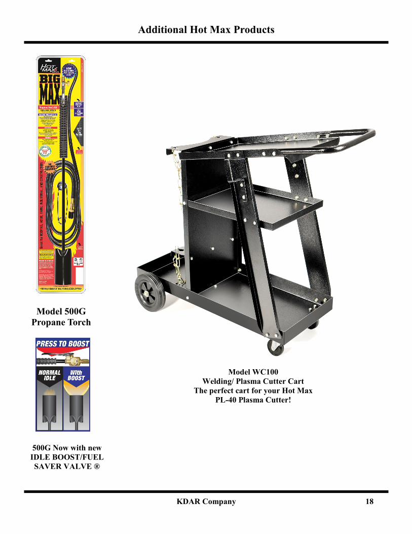
Additional Hot Max Products
Model 500G
Propane Torch
Model WC100
Welding/ Plasma Cutter Cart
The perfect cart for your Hot Max
PL-40 Plasma Cutter!
500G Now with new
IDLE BOOST/FUEL
SAVER VALVE ®