Embed Size (px)
Citation preview

Champion Series
5100725Rev H
Operator’s Manual
2690487 Massey Ferguson ZT 1844
5900608 Snapper ZT18441KHC
5900609 Snapper ZT19441KWV
2690449 Simplicity Champion 20K44
2690483 Simplicity Champion 20K44 (AUS/NZ)
2690451 Simplicity Champion 20BS50
2690452 Simplicity Champion 20BS50 (CE)
2690484 Simplicity Champion 20BS50 AUS/NZ
2690477 Massey Ferguson ZT2050
2690485 Massey Ferguson ZT2050 (CE)
5900610 Snapper ZT20501BV
5901166 Snapper ZT20501BV (CE)
5900735 Snapper 375ZB2050 (CE)
5900706 Snapper 400ZB2450
5900728 Massey Ferguson ZT2450
5900705 Simplicity Champion 26BS50
5900728 Simplicity Champion 26BS52
5900961 Simplicity Champion 27BS52
Not for
Reprod
uctio
n

2 www.simplicitymfg.com | www.snapper.com
Thank you for purchasing this quality-built product. We’re pleased that you’ve placed your confidence in the Simplicity and Snapper brand. When operated and maintained according to the instructions in this manual, your product will provide many years of dependable service.
This manual contains safety information to make you aware of the hazards and risks associated with this machine and how to avoid them. This machine is designed and intended to be used and maintained according to the manual for finish cutting of established lawns and is not intended for any other purpose. It is important that you read and understand these instructions thoroughly before attempting to start or operate this equipment. Save these original instructions for future reference.
See Features and Controls for the location of Identification Numbers
WARNINGThe engine exhaust from this product contains chemicals known to the State of California to cause cancer, birth defects, or other reproductive harm.
WARNINGBattery posts, terminals, and related accessories contain lead and lead compounds — chemicals known to the State of California to cause cancer and reproductive harm.Wash hands after handling.
PRODUCT REFERENCE DATA
Unit Model Number Unit SERIAL Number
Mower Deck Model Number Mower Deck SERIAL Number
Dealer Name Date Purchased
ENGINE REFERENCE DATA
Engine Make Engine Model
Engine Type/Spec Engine Code/Serial Number
Briggs & Stratton Power Products Group, LLCCopyright © 2012 Briggs & Stratton CorporationMilwaukee, WI, USA. All rights reserved.
SIMPLICITY is a trademark of Briggs & Stratton Corporation, Milwaukee, WI, USA.
SNAPPER is a trademark of Briggs & Stratton Corporation, Milwaukee, WI, USA.
Contact Information:
Simplicity Manufacturing, Inc.PO Box 702Milwaukee, WI, 53201-0702www.simplicitymfg.com
Snapper Products535 Macon St.McDonough, GA 30253www.snapper.com
Illustrated Parts Lists:The Illustrated Parts List for this machine can be downloaded from ferrisindustries.com.
Not for
Reprod
uctio
n

3
Table of ContentsSafety Rules & Information ................................ 4Identification Numbers ..................................... 10Safety Decals .................................................... 11Safety Interlock System ................................... 12Safety Icons ...................................................... 13Features & Controls ......................................... 14
Control Functions ..................................................14
Operation ........................................................... 16General Operating Safety .....................................16Checks Before Starting .........................................16Starting the Engine ...............................................17Stopping the Rider & Engine .................................17Pushing the Rider by Hand ...................................17Zero Turn Driving Practice ....................................18Mower Removal & Installation ..............................20Mowing ..................................................................21Mowing Recommendations ...................................21Mowing Methods ...................................................22Attaching a Trailer .................................................23
Maintenance ...................................................... 24Schedule ...............................................................24Lubrication ............................................................25Servicing the Mower Blades .................................26Checking Tire Pressures .......................................27Checking/Adding Fuel ...........................................27Fuel Filter ..............................................................27Engine Maintenance .............................................27Check/Fill Transmission Oil ..................................28Transmission Oil Filter Change .............................28Battery Maintenance .............................................29Storage .................................................................29Battery Charging ...................................................29Seat Adjustment ....................................................30Ground Speed Control Lever Adjustment .............30Speed Balancing Adjustment ................................31Cutting Height Adjustment ....................................31Neutral Adjustment ...............................................31Parking Brake Adjustment ....................................32Suspension Adjustment ........................................33PTO Clutch Adjustment ........................................34Blade Brake Check ...............................................34Mower Deck Leveling ............................................35Roller Bar Leveling ................................................36Mower Belt Replacement ......................................36Mower Deck Washout Port ...................................37Hydraulic Pump Drive Belt Replacement ..............38
Troubleshooting, Adjustments & Service ...... 39Troubleshooting the Rider .....................................39Troubleshooting the Mower ..................................40Common Cutting Problems ...................................41
Specifications ................................................... 42
NOTE: In this manual, “left” and “right” are referred to as seen from the operating position.
Not for
Reprod
uctio
n

4 www.simplicitymfg.com | www.snapper.com
OPERATOR SAFETY
Operating SafetyCongratulations on purchasing a superior-quality piece of lawn and garden equipment. Our products are designed and manufactured to meet or exceed all industry standards for safety.
Do not operate this machine unless you have been trained. Reading and understanding this operator’s manual is a way to train yourself.
Power equipment is only as safe as the operator. If it is misused, or not properly maintained, it can be dangerous! Remember, you are responsible for your safety and that of those around you.
Use common sense, and think through what you are doing. If you are not sure that the task you are about to perform can be safely done with the equipment you have chosen, ask a professional: contact your local authorized dealer.
Read the ManualThe operator’s manual contains important safety information you need to be aware of BEFORE you operate your unit as well as DURING operation.
Safe operating techniques, an explanation of the product’s features and controls, and maintenance information is included to help you get the most out of your equipment investment.
Be sure to completely read the Safety Rules and Information found on the following pages. Also completely read the Operation section.
ChildrenTragic accidents can occur with children. Do not allow them anywhere near the area of operation. Children are often attracted to the unit and mowing activity. Never assume that children will remain where you last saw them. If there is a risk that children may enter the area where you are mowing, have another responsible adult watch them.
Not for
Reprod
uctio
n
5
OPERATOR SAFETY
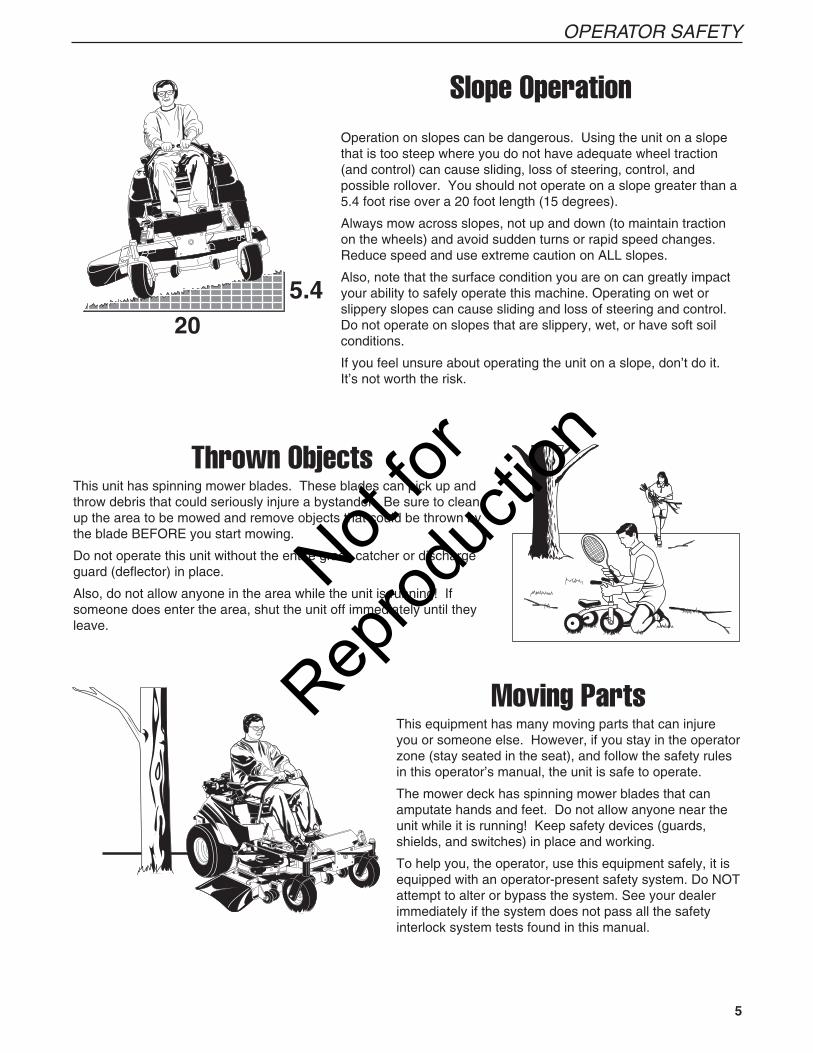
Slope OperationOperation on slopes can be dangerous. Using the unit on a slope that is too steep where you do not have adequate wheel traction (and control) can cause sliding, loss of steering, control, and possible rollover. You should not operate on a slope greater than a 5.4 foot rise over a 20 foot length (15 degrees).
Always mow across slopes, not up and down (to maintain traction on the wheels) and avoid sudden turns or rapid speed changes. Reduce speed and use extreme caution on ALL slopes.
Also, note that the surface condition you are on can greatly impact your ability to safely operate this machine. Operating on wet or slippery slopes can cause sliding and loss of steering and control. Do not operate on slopes that are slippery, wet, or have soft soil conditions.
If you feel unsure about operating the unit on a slope, don’t do it. It’s not worth the risk.
Thrown ObjectsThis unit has spinning mower blades. These blades can pick up and throw debris that could seriously injure a bystander. Be sure to clean up the area to be mowed and remove objects that could be thrown by the blade BEFORE you start mowing.
Do not operate this unit without the entire grass catcher or discharge guard (deflector) in place.
Also, do not allow anyone in the area while the unit is running! If someone does enter the area, shut the unit off immediately until they leave.
Moving PartsThis equipment has many moving parts that can injure you or someone else. However, if you stay in the operator zone (stay seated in the seat), and follow the safety rules in this operator’s manual, the unit is safe to operate.
The mower deck has spinning mower blades that can amputate hands and feet. Do not allow anyone near the unit while it is running! Keep safety devices (guards, shields, and switches) in place and working.
To help you, the operator, use this equipment safely, it is equipped with an operator-present safety system. Do NOT attempt to alter or bypass the system. See your dealer immediately if the system does not pass all the safety interlock system tests found in this manual.
Not for
Reprod
uctio
n

6 www.simplicitymfg.com | www.snapper.com
OPERATOR SAFETY
Enclosed AreasOnly operate this unit outdoors and away from unventilated areas such as inside garages or enclosed trailers. The engine emits poisonous carbon monoxide gas and prolonged exposure in an enclosed area can result in serious injury or death.
Fuel and MaintenanceAlways disengage all drives, shutoff the engine, and remove the key before doing any cleaning, refueling, or servicing.
Gasoline and its vapors are extremely flammable. Do not smoke while operating or refueling. Do not add fuel while engine is hot or running. Allow engine to cool for at least 3 minutes prior to adding fuel.
Do not add fuel indoors, in an enclosed trailer, garage, or any other enclosed area that is not well ventilated. Gasoline spills should be cleaned up promptly and before operation begins.
Gasoline should be stored only in sealed containers approved for fuel.
Proper maintenance is critical to the safety and performance of your unit. Keep the unit free of grass, leaves, and excess oil. Be sure to perform the maintenance procedures listed in this manual, especially periodically testing the safety system.
Retaining Walls, Drop-offs, and WaterRetaining walls and drop-offs around steps and water are a common hazard. Give yourself a minimum of two mower widths of clearance around these hazards and hand-trim with a walk behind mower or string trimmer. Wheels dropping over retaining walls, edges, ditches, embankments, or into water can cause rollovers, which may result in serious injury, death, or drowning.
Not for
Reprod
uctio
n

7
OPERATOR SAFETY
GENERAL OPERATION 1. Read, understand, and follow all instructions in the
manual and on the unit before starting. 2. Do not put hands or feet near rotating parts or
under the machine. Keep clear of the discharge opening at all times.
3. Only allow responsible adults, who are familiar with the instructions, to operate the unit (local regulations can restrict operator age).
4. Clear the area of objects such as rocks, toys, wire, etc., which could be picked up and thrown by the blade(s).
5. Be sure the area is clear of other people before mowing. Stop the unit if anyone enters the area.
6. Never carry passengers. 7. Do not mow in reverse unless absolutely
necessary. Always look down and behind before and while travelling in reverse.
8. Never direct discharge material toward anyone. Avoid discharging material against a wall or obstruction. Material may ricochet back toward the operator. Stop the blade(s) when crossing gravel surfaces.
9. Do not operate the machine without the entire grass catcher, discharge guard (deflector), or other safety devices in place and operational.
10. Slow down before turning. 11. Never leave a running unit unattended. Always
disengage the blades (PTO), set parking brake, stop engine, and remove keys before dismounting.
12. Disengage blades (PTO) when not mowing. Shut off engine and wait for all parts to come to a complete stop before cleaning the machine, removing the grass catcher, or unclogging the discharge guard.
13. Operate the machine only in daylight or good artificial light.
14. Do not operate the unit while under the influence of alcohol or drugs.
15 Watch for traffic when operating near or crossing roadways.
16. Use extra care when loading or unloading the unit into a trailer or truck.
17. Always wear eye protection when operating this unit.
18. Data indicates that operators, age 60 years and above, are involved in a large percentage of power equipment-related injuries. These operators should evaluate their ability to operate the equipment safely enough to protect themselves and others from injury.
19. Follow the manufacturer’s recommendations for wheel weights or counterweights.
20. Keep in mind the operator is responsible for accidents occurring to other people or property.
21. All drivers should seek and obtain professional and practical instruction.
22. Always wear substantial footwear and trousers. Never operate when barefoot or wearing sandals.
23. Before using, always visually check that the blades and blade hardware are present, intact, and secure. Replace worn or damaged parts.
24. Disengage attachments before: refueling, removing an attachment, making adjustments (unless the adjustment can be made from the operator’s position).
25. When the machine is parked, stored, or left unattended, lower the cutting means unless a positive mechanical lock is used.
26. Before leaving the operator’s position for any reason, engage the parking brake (if equipped), disengage the blades (PTO), stop the engine, and remove the key.
27. To reduce fire hazard, keep the unit free of grass, leaves, & excess oil. Do not stop or park over dry leaves, grass, or combustible materials.
28. OSHA regulations may require the use of hearing protection when exposed to sound levels greater than 85 dBA for an 8 hour time period.
Read these safety rules and follow them closely. Failure to obey these rules could result in loss of control of unit, severe personal injury or death to you, or bystanders, or damage to property or equipment. This mowing deck is capable of amputating hands and feet and throwing objects. The triangle in text signifies important cautions or warnings which must be followed.
TRANSPORTING AND STORAGE 1. When transporting the unit on an open trailer,
make sure it is facing forward, in the direction of travel. If the unit is facing backwards, wind lift could damage the unit.
2. Always observe safe refueling and fuel handling practices when refueling the unit after transportation or storage.
3. Never store the unit (with fuel) in an enclosed poorly ventilated structure. Fuel vapors can travel to an ignition source (such as a furnace, water heater, etc.) and cause an explosion. Fuel vapor is also toxic to humans and animals.
4. Always follow the engine manual instructions for storage preparations before storing the unit for both short and long term periods.
5. Always follow the engine manual instructions for proper start-up procedures when returning the unit to service.
6. Never store the unit or fuel container inside where there is an open flame or pilot light, such as in a water heater. Allow unit to cool before storing.
CAUTIONThis machine produces sound levels in excess of 85 dBA at the operator’s ear and can cause hearing loss through extended periods of exposure.
Wear hearing protection when operating this machine.
WARNINGIt is a violation of California Public Resource Code, Section 4442, to use or operate the engine on any forest-covered, brush-covered or grass-covered land unless the exhaust system is equipped with a spark arrester, as defined in Section 4442, maintained in effective working order. Other states or federal jurisdictions may have similar laws. Contact an Authorized Service Dealer to obtain a spark arrester designed for the exhaust system installed on this engine.
Not for
Reprod
uctio
n

8 www.simplicitymfg.com | www.snapper.com
OPERATOR SAFETY
TOWED EQUIPMENT (RIDE-ON UNITS) 1. Tow only with a machine that has a hitch designed
for towing. Do not attach towed equipment except at the hitch point.
2. Follow the manufacturer’s recommendations for weight limit for towed equipment and towing on slopes. See attaching a trailer under OPERATION.
3. Never allow children or others in or on towed equipment.
4. On slopes, the weight of the towed equipment may cause loss of traction and loss of control.
5. Travel slowly and allow extra distance to stop. 6. Do not shift to neutral and coast down hill.
CHILDRENTragic accidents can occur if the operator is not alert to the presence of children. Children are often attracted to the unit and the mowing activity. Never assume that children will remain where you last saw them. 1. Keep children out of the mowing area and under
the watchful care of another responsible adult. 2. Be alert and turn unit off if children enter the area. 3. Before and during reverse operation, look behind
and down for small children. 4. Never carry children, even with the blade(s) off.
They may fall off and be seriously injured or interfere with safe unit operation. Children who have been given rides in the past may suddenly appear in the mowing area for another ride and be run over or backed over by the machine.
5. Never allow children to operate the unit. 6. Use extra care when approaching blind corners,
shrubs, trees, or other objects that may obscure vision.
EMISSIONS 1. Engine exhaust from this product contains
chemicals known, in certain quantities, to cause cancer, birth defects, or other reproductive harm.
2. Look for the relevant Emissions Durability Period and Air Index information on the engine emissions label.
IGNITION SYSTEM 1. This spark ignition system complies with Canadian
ICES-002.
SLOPE OPERATIONSlopes are a major factor related to loss-of-control and tip-over accidents, which can result in severe injury or death. Operation on all slopes requires extra caution. If you cannot back up the slope or if you feel uneasy on it, do not operate on it.Control of a walk-behind or ride-on machine sliding on a slope will not be regained by the application of the brake. The main reasons for loss of control are: insufficient tire grip on the ground, speed too fast, inadequate braking, the type of machine is unsuitable for its task, lack of awareness of the ground conditions, incorrect hitching and load distribution. 1. Mow across slopes, not up and down. 2. Watch for holes, ruts, or bumps. Uneven terrain
could overturn the unit. Tall grass can hide obstacles.
3. Choose a slow speed so that you will not have to stop or change speeds while on the slope.
4. Do not mow on wet grass. Tires may loose traction.
5. Avoid starting, stopping, or turning on a slope. If tires lose traction (i.e. machine stops forward motion on a slope), disengage the blade(s) (PTO) and drive slow off the slope.
6. Keep all movement on slopes slow and gradual. Do not make sudden changes in speed or direction, which could cause the machine to rollover.
7. Use extra care while operating machines with grass catchers or other attachments; they can affect the stability of the unit. Do not use on steeps slopes.
8. Do not try to stabilize the machine by putting your foot on the ground (ride-on units).
9. Do not mow near drop-offs, ditches, or embankments. The mower could suddenly turn over if a wheel is over the edge of a cliff or ditch, or if an edge caves in.
10. Do not use grass catchers on steep slopes. 11. Do not mow slopes if you cannot back up them. 12. See your authorized dealer/retailer for
recommendations of wheel weights or counterweights to improve stability.
13. Remove obstacles such as rocks, tree limbs, etc. 14. Use slow speed. Tires may lose traction on slopes
even though the brakes are functioning properly. 15. Do not turn on slopes unless necessary, and then,
turn slowly and gradually uphill, if possible. Never mow down slopes.
WARNINGDo not use this machine on slopes greater than 15 degrees.*Select slow ground speed before driving onto slope. Use extra caution when operating on slopes with rear-mounted grass catchers.Mow across the face of slopes, not up and down,use caution when changing directions and DO NOT START OR STOP ON SLOPE.
*This limit was determined per CEN Standard EN 836:1997, Section 5.2.2 and is based on the EN 836 Stability Test procedure described in Section 4.2.4.2. The 15 degree “limit of stability” is equal to 50% of the angle at which machine lift-off occurred in static tests. Actual dynamic stability may vary depending on operating conditions.
Not for
Reprod
uctio
n

9
OPERATOR SAFETY
SERVICE AND MAINTENANCESafe Handling of Gasoline 1. Extinguish all cigarettes, cigars, pipes, and other
sources of ignition. 2. Use only approved gasoline containers. 3. Never remove the gas cap or add fuel with the
engine running. Allow the engine to cool before refueling.
4. Never fuel the machine indoors. 5. Never store the machine or fuel container where
there is an open flame, spark, or pilot light such as near a water heater or other appliance.
6. Never fill containers inside a vehicle or on a truck bed with a plastic bed liner. Always place containers on the ground away from your vehicle before filling.
7. Remove gas-powered equipment from the truck or trailer and refuel it on the ground. If this is not possible, then refuel such equipment on a trailer with a portable container, rather than from a gasoline dispenser nozzle.
8. Keep nozzle in contact with the rim of the fuel tank or container opening at all times until fueling is complete. Do not use a nozzle lock-open device.
9. If fuel is spilled on clothing, change clothing immediately.
10. Never over-fill the fuel tank. Replace gas cap and tighten securely.
11. Use extra care in handling gasoline and other fuels. They are flammable and vapors are explosive.
12. If fuel is spilled, do not attempt to start the engine but move the machine away from the area of spillage and avoid creating any source of ignition until fuel vapors have dissipated.
13. Replace all fuel tank caps and fuel container caps securely.
Service & Maintenance 1. Never run the unit in an enclosed area where
carbon monoxide fumes may collect. 2. Keep nuts and bolts, especially blade attachment
bolts, tight and keep equipment in good condition. 3. Never tamper with safety devices. Check their
proper operation regularly and make necessary repairs if they are not functioning properly.
4. Keep unit free of grass, leaves, or other debris build-up. Clean up oil or fuel spillage. and remove any fuel-soaked debris. Allow machine to cool before storage.
5. If you strike an object, stop and inspect the machine. Repair, if necessary, before restarting.
6. Never make adjustments or repairs with the engine running.
7. Check grass catcher components and the discharge guard frequently and replace with manufacturer’s recommended parts, when necessary.
8. Mower blades are sharp. Wrap the blade or wear gloves, and use extra caution when servicing them.
9. Check brake operation frequently. Adjust and service as required.
10. Maintain or replace safety and instructions labels, as necessary.
11. Do not remove the fuel filter when the engine is hot as spilled gasoline may ignite. Do not spread fuel
line clamps further than necessary. Ensure clamps grip hoses firmly over the filter after installation.
12. Do not use gasoline containing METHANOL, gasohol containing more than 10% ETHANOL, gasoline additives, or white gas because engine/fuel system damage could result.
13. If the fuel tank must be drained, it should be drained outdoors.
14. Replace faulty silencers/mufflers. 15. Maintain or replace safety and instruction labels as
necessary. 16. Use only factory authorized replacement parts
when making repairs. 17. Always comply with factory specifications on all
settings and adjustments. 18. Only authorized service locations should be utilized
for major service and repair requirements. 19. Never attempt to make major repairs on this unit
unless you have been properly trained. Improper service procedures can result in hazardous operation, equipment damage and voiding of manufacturer’s warranty.
20. On multiple blade mowers, take care as rotating one blade can cause other blades to rotate.
21. Do not change engine governor settings or over-speed the engine. Operating the engine at excessive speed can increase the hazard of personal injury.
22. Disengage drive attachments, stop the engine, remove the key, and disconnect the spark plug wire(s) before: clearing attachment blockages and chutes, performing service work, striking an object, or if the unit vibrates abnormally. After striking an object, inspect the machine for damage and make repairs before restarting and operating the equipment.
23. Never place hands near the moving parts, such as a hydro pump cooling fan, when the tractor is running. (Hydro pump cooling fans are typically located on top of the transaxle).
24. Units with hydraulic pumps, hoses, or motors: WARNING: Hydraulic fluid escaping under pressure may have sufficient force to penetrate skin and cause serious injury. If foreign fluid is injected into the skin it must be surgically removed within a few hours by a doctor familiar with this form of injury or gangrene may result. Keep body and hands away from pin holes or nozzles that eject hydraulic fluid under high pressure. Use paper or cardboard, and not hands, to search for leaks. Make sure all hydraulic fluid connections are tight and all hydraulic hoses and lines are in good condition before applying pressure to the system. If leaks occur, have the unit serviced immediately by your authorized dealer.
25. WARNING: Stored energy device. Improper release of springs can result in serious personal injury. Springs should be removed by an authorized technician.
26. Models equipped with an engine radiator: WARNING: Stored energy device. To prevent serious bodily injury from hot coolant or steam blow-out, never attempt to remove the radiator cap while the engine is running. Stop the engine and wait until it is cool. Even then, use extreme care when removing the cap.
Not for
Reprod
uctio
n

10 www.simplicitymfg.com | www.snapper.com
OPERATOR SAFETY
Unit ID Tag
Mower ID Tag
When contacting your authorized dealer for replacement parts, service, or information you MUST have these numbers.
Record your model name/number, manufacturer’s identification numbers, and engine serial numbers in the space provided for easy access. These numbers can be found in the locations shown.
NOTE: For location of engine identification numbers, refer to the engine owner’s manual.
CE Models: Place the extra copy of the identification tag in the manual
Model xxxxxxx
Serial xxxxxxxxxx
xxxxxxxxxxxxxxxxxxxx
20xx
kg:kW:xxxx
xxxx.xxmax
XXXBRIGGS & STRATTON CORP.POWER PRODUCTS GROUP, LLCMILWAUKEE, WI 53201 USA
SAMPLE
SAMPLE
SAMPLE
SAMPLE
North American / CE Models
CE Models (Only)
Model xxxxxxx
Serial xxxxxxxxxx
xxxxxxxxxxxxxxxxxxxx
20xx
kg:kW:xxxx
xxxx.xxmax
XXXBRIGGS & STRATTON CORP.POWER PRODUCTS GROUP, LLCMILWAUKEE, WI 53201 USA
A
B
C
D
E F
I
J
H
G
CE IDENTIFICATION TAG MARKINGS A. Manufacturer’s Identification Number
B. Product Description
C. Serial Number
D. Manufacturer’s Address
E. CE Compliance Logo
F. Year of Manufacture
G. Maximum Engine Speed in Rotations per Minute
H. Power Rating in Kilowatts
I. Mass of Unit in Kilograms
J. Sound Power in Decibels *
This unit complies with European Harmonized Lawn Mower Standard EN 836, European Machinery Directive 98/37/EC, and European EMC Directive 89/336/EC
* Tested according to 2000/14/EC
IDENTIFICATION NUMBERS
Not for
Reprod
uctio
n
11
OPERATOR SAFETY
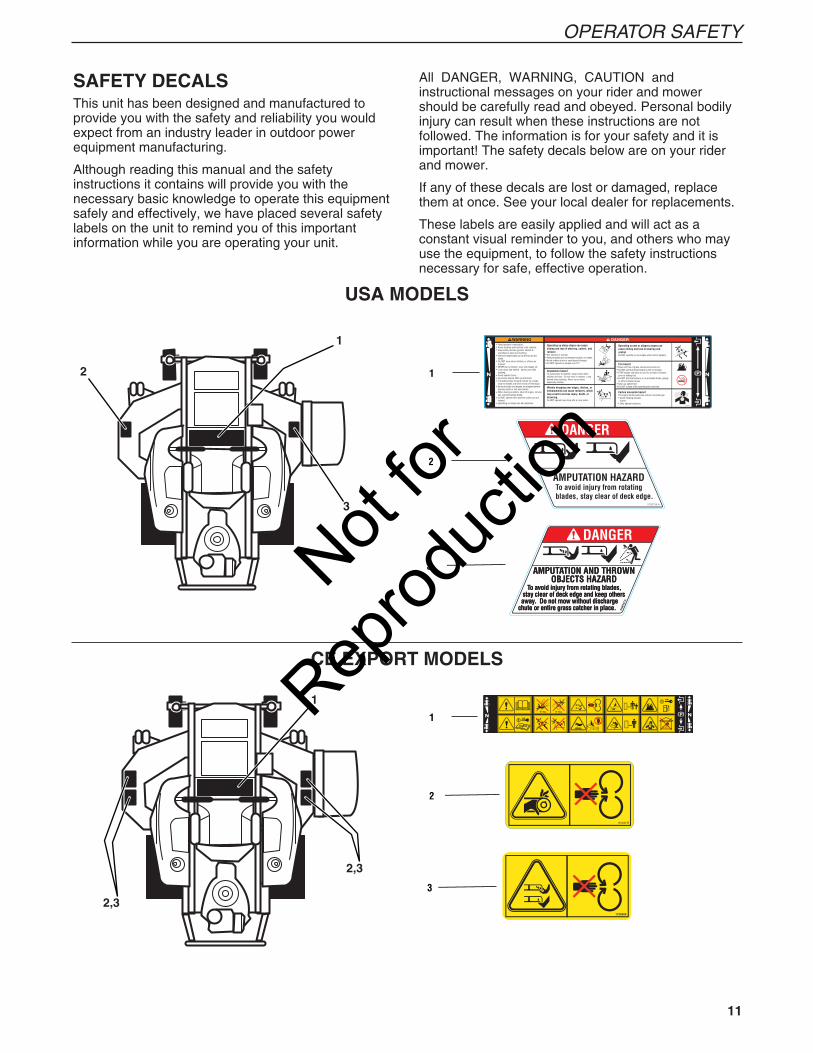
SAFETY DECALSThis unit has been designed and manufactured to provide you with the safety and reliability you would expect from an industry leader in outdoor power equipment manufacturing.
Although reading this manual and the safety instructions it contains will provide you with the necessary basic knowledge to operate this equipment safely and effectively, we have placed several safety labels on the unit to remind you of this important information while you are operating your unit.
3 AMPUTATION AND THROWNOBJECTS HAZARD
To avoid injury from rotating blades, stay clear of deck edge and keep others away. Do not mow without dischargechute or entire grass catcher in place. 51
0013
7 A
2
1
1
2
3
5101233
USA MODELS
CE EXPORT MODELS
All DANGER, WARNING, CAUTION and instructional messages on your rider and mower should be carefully read and obeyed. Personal bodily injury can result when these instructions are not followed. The information is for your safety and it is important! The safety decals below are on your rider and mower.
If any of these decals are lost or damaged, replace them at once. See your local dealer for replacements.
These labels are easily applied and will act as a constant visual reminder to you, and others who may use the equipment, to follow the safety instructions necessary for safe, effective operation.
1
2
3
1
2,3
2,3
Not for
Reprod
uctio
n

12 www.simplicitymfg.com | www.snapper.com
OPERATOR SAFETY
NORTH AMERICAN MODELS ONLY:SAFETY INTERLOCK SYSTEM
This unit is equipped with safety interlock switches. These safety systems are present for your safety, do not attempt to bypass safety switches, and never tamper with safety devices. Check their operation regularly.
Operational SAFETY Checks
Test 1 — Engine should NOT crank if:
• PTO switch is engaged, OR • Parking brake is not engaged, OR • Motion control handles are not in the NEUTRAL
position.
Test 2 — Engine SHOULD crank and start if:
• PTO switch is NOT engaged, AND • Parking brake is engaged, AND • Motion control handles are locked in the
NEUTRAL position.
Test 3 — Engine should SHUT OFF if:
• Operator rises off seat with PTO engaged, OR • Operator rises off seat with parking brake
disengaged. • Operator moves motion control handles out of
their neutral positions before disengaging parking brake.
Test 4 — Blade Brake Check
Mower blades and mower drive belt should come to a complete stop within five (5) seconds after electric PTO switch is turned off (or operator rises off seat). If mower drive belt does not stop within five (5) seconds, see your dealer.
NOTE: Once the engine has stopped, PTO switch must be turned off, parking brake must be engaged, and the motion control handles must be locked in the NEUTRAL position after the operator returns to the seat in order to start the engine.
WARNINGIf the unit does not pass a safety test, do not operate it. See your authorized dealer. Under no circumstance should you attempt to defeat the purpose of the safety interlock system.
EXPORT MODELS ONLY:
SAFETY INTERLOCK SYSTEM
This unit is equipped with safety interlock switches. These safety systems are present for your safety, do not attempt to bypass safety switches, and never tamper with safety devices. Check their operation regularly.
Operational SAFETY Checks
Test 1 — Engine should NOT crank if:
• PTO switch is engaged, OR • Parking brake is not engaged, OR • Motion control handles are not in the NEUTRAL
position.
Test 2 — Engine SHOULD crank and start if:
• PTO switch is NOT engaged, AND • Parking brake is engaged, AND • Motion control handles are locked in the
NEUTRAL position, AND • Operator is in seat.
Test 3 — Engine should SHUT OFF if:
• Operator rises off seat under any condition. • Operator moves motion control handles out of
their neutral positions before disengaging parking brake.
Test 4 — Blade Brake Check
Mower blades and mower drive belt should come to a complete stop within five (5) seconds after electric PTO switch is turned off (or operator rises off seat). If mower drive belt does not stop within five (5) seconds, see your dealer.
NOTE: Once the engine has stopped, PTO switch must be turned off, parking brake must be engaged, and the motion control handles must be locked in the NEUTRAL position after the operator returns to the seat in order to start the engine.
WARNINGIf the unit does not pass a safety test, do not operate it. See your authorized dealer. Under no circumstance should you attempt to defeat the purpose of the safety interlock system.
Not for
Reprod
uctio
n

13
OPERATOR SAFETY
CE SAFETY ICONSWarning: Read Operator’s Manual.Read and understand the Operator’s Manual before using this machine.Danger: Thrown Objects.This machine is capable of throwing objects and debris. Keep bystanders away.Warning: Remove Key Before Servicing.Remove the key and consult technical literature before performing repairs or maintenance.
Danger: Dismemberment.This machine can amputate limbs. Keep bystanders and children away when engine is running.Danger: Dismemberment.This mower deck can amputate limbs. Keep hands and feet away from blades.
Danger: Carbon Monoxide Poisoning.Do not operate the engine in an unventilated area.
Danger: Dismemberment.This machine can crush and cut. Keep hands away from belts and pulleys.
Safety IconsThe alert symbol is used to identity safety information about hazards that can result in personal injury. A signal word (DANGER, WARNING, or CAUTION) is used with the alert symbol to indicate the likelihood and the potential severity of the injury. In addition, a hazard icon may be used to represent the type of hazard. An explanation of hazard levels and icons are as follows:
DANGERThis indicates a hazard which, if not avoided, will result in serious injury or death.
WARNINGThis indicates a hazard which, if not avoided, could result in serial injury or death.
CAUTIONThis indicates a hazard which, if not avoided, might result in minor or moderate injury.
CAUTION or NOTICEThese messages presented without the alert symbol indicate a situation where the unit or property could be damaged.
Hazard Safety Icon
Alert
Toxic Fumes
Read the Manual
Open flame hazard
Fire Hazard
Amputation Rotating PartsAmputation Hand in Blade
Hazard Safety Icon
Amputation Foot in Blade
Thrown Objects
Maintain a safe distanceKeep children away
Hot surface
Wear Protective Gear
Pinch Point
NORTH AMERICAN SAFETY ICONS
Rollover Hazard
Overhead Obstacles
Danger: Machine Rollover.Operating on steep slopes can cause sliding and loss of steering, control and rollover. Do not use this machine on slopes greater than 15°. This limit was determined per CEN Standard EN 836:1997, Section 5.2.2 and is based on the EN 836 Stability Test procedure described in Section 4.2.4.2. The 15 degree “limit of stability” is equal to 50% of the angle at which machine lift-off occurred in static tests. Actual dynamic stability may vary depending on operating conditions.
Danger: Machine Rollover.Do not operate on any slopes when wet or slippery. Do not operate near drop-offs or near water.
Danger: Fire Hazard.Keep unit free of grass, leaves and excess oil. Do not add fuel while engine is hot or running. Stop engine and allow to cool for at least 3 minutes prior to adding fuel. Do not add fuel indoors, in an enclosed trailer, garage or other enclosed areas. Clean up spilled fuel. Do not smoke while operating this machine.Warning: Hot SurfaceAvoid contact with engine and hot surfaces. Wait for unit to cool before touching.
Not for
Reprod
uctio
n
14 www.simplicitymfg.com | www.snapper.com
FEATURES AND CONTROLS
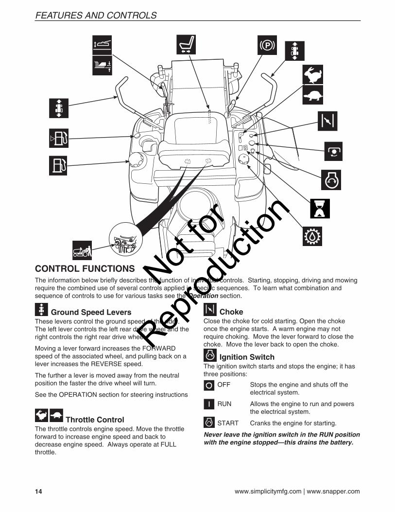
Ground Speed LeversThese levers control the ground speed of the rider. The left lever controls the left rear drive wheel and the right controls the right rear drive wheel.
Moving a lever forward increases the FORWARD speed of the associated wheel, and pulling back on a lever increases the REVERSE speed.
The further a lever is moved away from the neutral position the faster the drive wheel will turn.
See the OPERATION section for steering instructions
Throttle ControlThe throttle controls engine speed. Move the throttle forward to increase engine speed and back to decrease engine speed. Always operate at FULL throttle.
CONTROL FUNCTIONSThe information below briefly describes the function of individual controls. Starting, stopping, driving and mowing require the combined use of several controls applied in specific sequences. To learn what combination and sequence of controls to use for various tasks see the Operation section.
ChokeClose the choke for cold starting. Open the choke once the engine starts. A warm engine may not require choking. Move the lever forward to close the choke. Move the lever back to open the choke.
Ignition SwitchThe ignition switch starts and stops the engine; it has three positions:
OFF Stops the engine and shuts off the electrical system.
RUN Allows the engine to run and powers the electrical system.
START Cranks the engine for starting.
Never leave the ignition switch in the RUN position with the engine stopped—this drains the battery.
Not for
Reprod
uctio
n
15
FEATURES AND CONTROLS
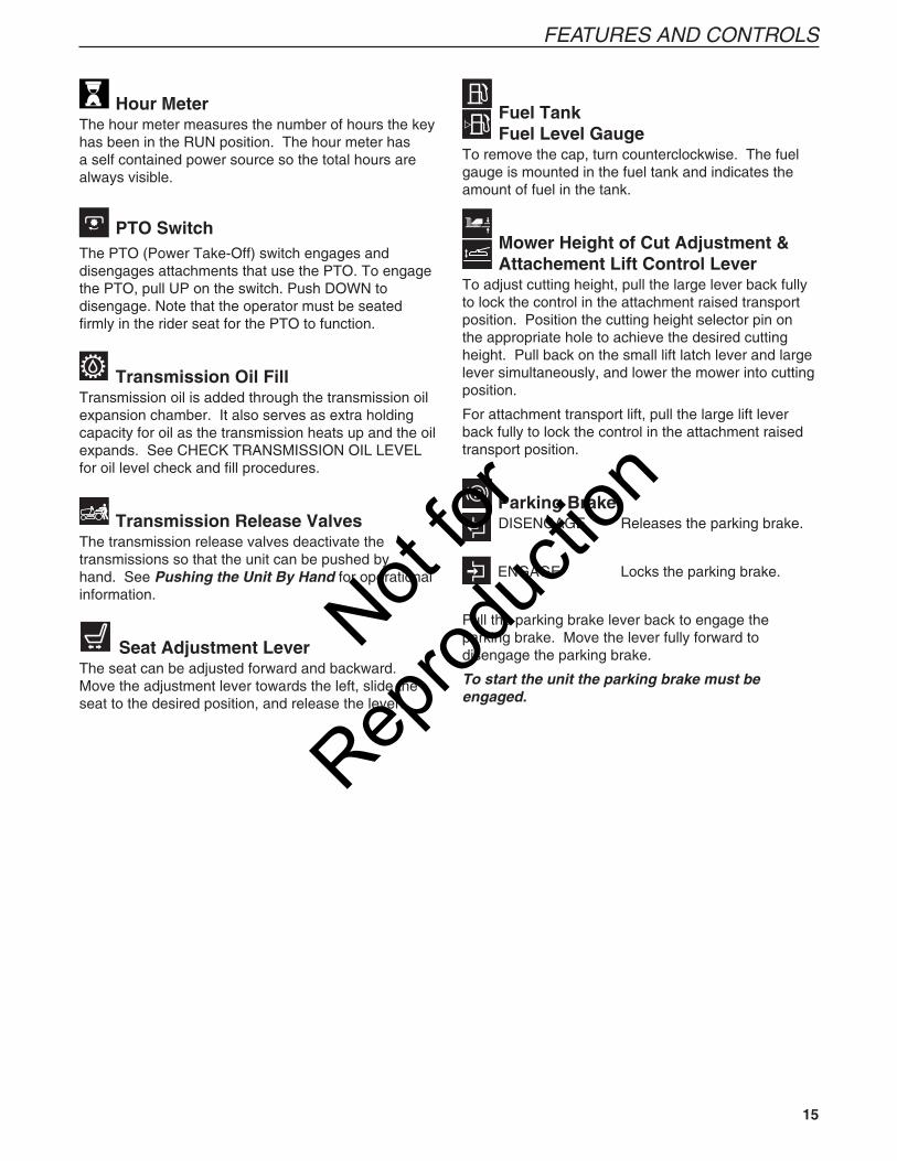
Hour MeterThe hour meter measures the number of hours the key has been in the RUN position. The hour meter has a self contained power source so the total hours are always visible.
PTO SwitchThe PTO (Power Take-Off) switch engages and disengages attachments that use the PTO. To engage the PTO, pull UP on the switch. Push DOWN to disengage. Note that the operator must be seated firmly in the rider seat for the PTO to function.
Transmission Oil Fill Transmission oil is added through the transmission oil expansion chamber. It also serves as extra holding capacity for oil as the transmission heats up and the oil expands. See CHECK TRANSMISSION OIL LEVEL for oil level check and fill procedures.
Transmission Release Valves The transmission release valves deactivate the transmissions so that the unit can be pushed by hand. See Pushing the Unit By Hand for operational information.
Seat Adjustment LeverThe seat can be adjusted forward and backward. Move the adjustment lever towards the left, slide the seat to the desired position, and release the lever.
Fuel TankFuel Level Gauge
To remove the cap, turn counterclockwise. The fuel gauge is mounted in the fuel tank and indicates the amount of fuel in the tank.
Mower Height of Cut Adjustment &Attachement Lift Control Lever
To adjust cutting height, pull the large lever back fully to lock the control in the attachment raised transport position. Position the cutting height selector pin on the appropriate hole to achieve the desired cutting height. Pull back on the small lift latch lever and large lever simultaneously, and lower the mower into cutting position.
For attachment transport lift, pull the large lift lever back fully to lock the control in the attachment raised transport position.
Parking BrakeDISENGAGE Releases the parking brake.
ENGAGE Locks the parking brake.
Pull the parking brake lever back to engage the parking brake. Move the lever fully forward to disengage the parking brake.
To start the unit the parking brake must be engaged.
Not for
Reprod
uctio
n
16 www.simplicitymfg.com | www.snapper.com
OPERATION
GENERAL OPERATING SAFETYBefore first time operation:
• Be sure to read all information in the Safety and Operation sections before attempting to operate this tractor and mower.
• Become familiar with all of the controls and how to stop the unit.
• Drive in an open area without mowing to become accustomed to the unit brake lever or set the parking brake.
CHECKS BEFORE STARTING • Check that crankcase is filled to full mark on
dipstick. See the engine Operator’s Manual for instructions and oil recommendations.
• Make sure all nuts, bolts, screws and pins are in place and tight.
• Adjust the seat position, and make certain you can reach all controls from operator’s position.
• Fill the fuel tank with fresh fuel. Refer to engine manual for fuel recommendations.
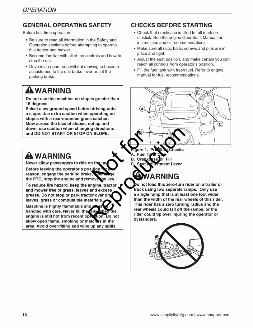
Figure 1. Pre-Start ChecksA. Fuel Tank CapB. Crankcase Oil FillC. Seat Adjustment Lever
A
C
B
WARNINGNever allow passengers to ride on the unit.
Before leaving the operator’s position for any reason, engage the parking brake, disengage the PTO, stop the engine and remove the key.
To reduce fire hazard, keep the engine, tractor and mower free of grass, leaves and excess grease. Do not stop or park tractor over dry leaves, grass or combustible materials.
Gasoline is highly flammable and must be handled with care. Never fill the tank when the engine is still hot from recent operation. Do not allow open flame, smoking or matches in the area. Avoid over-filling and wipe up any spills.
WARNINGDo not use this machine on slopes greater than 15 degrees. Select slow ground speed before driving onto a slope. Use extra caution when operating on slopes with a rear-mounted grass catcher.Mow across the face of slopes, not up and down, use caution when changing directions and DO NOT START OR STOP ON SLOPE.
WARNINGDo not load this zero-turn rider on a trailer or truck using two separate ramps. Only use a single ramp that is at least one foot wider than the width of the rear wheels of this rider. This rider has a zero turning radius and the rear wheels could fall off the ramps, or the rider could tip over injuring the operator or bystanders.
Not for
Reprod
uctio
n
17
OPERATION
WARNINGIf you do not understand how a specific control functions, or have not yet thoroughly read the FEATURES & CONTROLS section, do so now.Do NOT attempt to operate the tractor without first becoming familiar with the location and function of ALL controls.
STARTING THE ENGINE 1. While sitting in the operator’s seat, engage the
parking brake and make sure the PTO switch is disengaged and the motion control handles are locked in the NEUTRAL position.
2. NOTE: A warm engine may not require choking.
Set the engine throttle control to FAST throttle position. Then fully close the choke by pulling the knob OUT fully.
3. Insert the key into the ignition switch and turn it to START.
4. After the engine starts, gradually open the choke (push knob down fully).
Warm up the engine by running it for at least a minute before engaging the PTO switch or driving the rider.
5. After warming the engine, ALWAYS operate the unit at FULL THROTTLE when mowing.
In the event of an emergency the engine can be stopped by simply turning the ignition switch to STOP. Use this method only in emergency situations. For normal engine shut down follow the procedure given in STOPPING THE RIDER.
STOPPING THE RIDER AND ENGINE 1. Returning the ground speed control levers to the
middle position will stop tractor movement. Pivot the levers outward and lock them in NEUTRAL.
2. Disengage the PTO by pushing down on the PTO switch.
3. Engage the parking brake by pulling the handle up until it locks into position.
4. Move the throttle control to mid-throttle position and turn the ignition key to OFF. Remove the key.
PUSHING THE RIDER BY HAND 1. Disengage the PTO, engage the parking brake,
turn the ignition OFF, and remove the key. 2. Lift the seat plate to gain access to the hydraulic
pumps. 3. To disengage the pumps (free-wheel position),
turn the hydraulic release valves (A, Figure 2) located on the pumps COUNTER-CLOCKWISE a maximum of 2 full turns.
4. Disengage the parking brake. The tractor can now be pushed by hand. 5. After moving the tractor, re-engage the pumps
(drive position) by turning the release valves CLOCKWISE and tighten to 80-120 in. lbs. of torque.
DO NOT TOW RIDERTowing the unit will cause hydraulic pump and wheel motor damage. Do not use another vehicle to push or pull this unit.
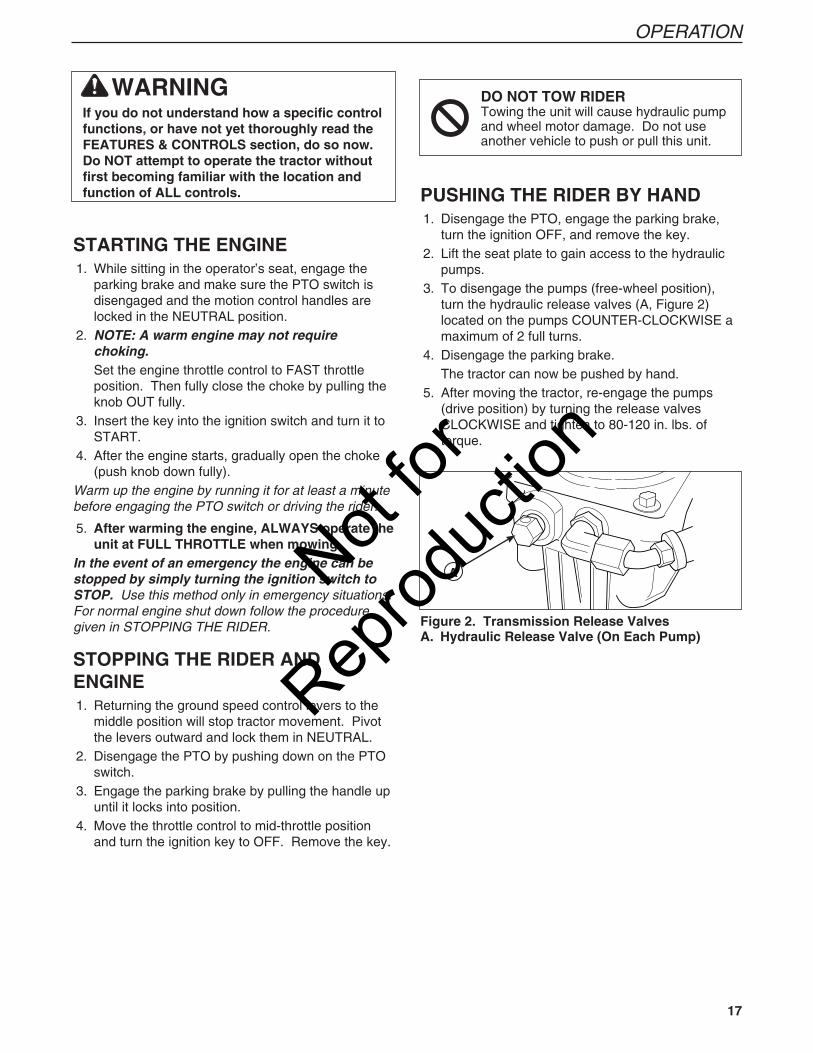
Figure 2. Transmission Release ValvesA. Hydraulic Release Valve (On Each Pump)
ANot for
Reprod
uctio
n
18 www.simplicitymfg.com | www.snapper.com
OPERATION
ZERO TURNDRIVING PRACTICEThe lever controls of the Zero Turn rider are responsive, and learning to gain a smooth and efficient control of the rider’s forward, reverse, and turning movements will take some practice.
Spending some time going through the maneuvers shown and becoming familiar with how the unit accelerates, travels, and steers — before you begin mowing —is absolutely essential to getting the most out of the Zero Turn rider.
Locate a smooth, flat area of your lawn — one with plenty of room to maneuver. (Clear the area of objects, people and animals before you begin.) Operate the unit at mid-throttle during this practice session (ALWAYS operate at full throttle when mowing), and turn slowly to prevent tire slippage and damage to your lawn.
We suggest you begin with the Smooth Travel procedure to the right, and then advance through the forward, reverse, and turning maneuvers.
You must release the parking brake prior to moving the control levers inward.
BASIC DRIVING
Forward Travel PracticeGradually move both ground speed control levers — evenly FORWARD from neutral. Slow down and repeat.
NOTE: Straight forward travel takes practice. If necessary, top speed can be balance-adjusted — see the Speed Balancing Adjustment in the Adjustments section near the back of this manual.
Reverse Travel PracticeLOOK DOWN AND BEHIND, then gradually move both ground speed control levers evenly BACK from neutral. Slow down and repeat.
NOTE: Practice backing up for several minutes before attempting to do so near objects. The rider turns sharply in reverse as well as forward, and backing up straight takes practice.
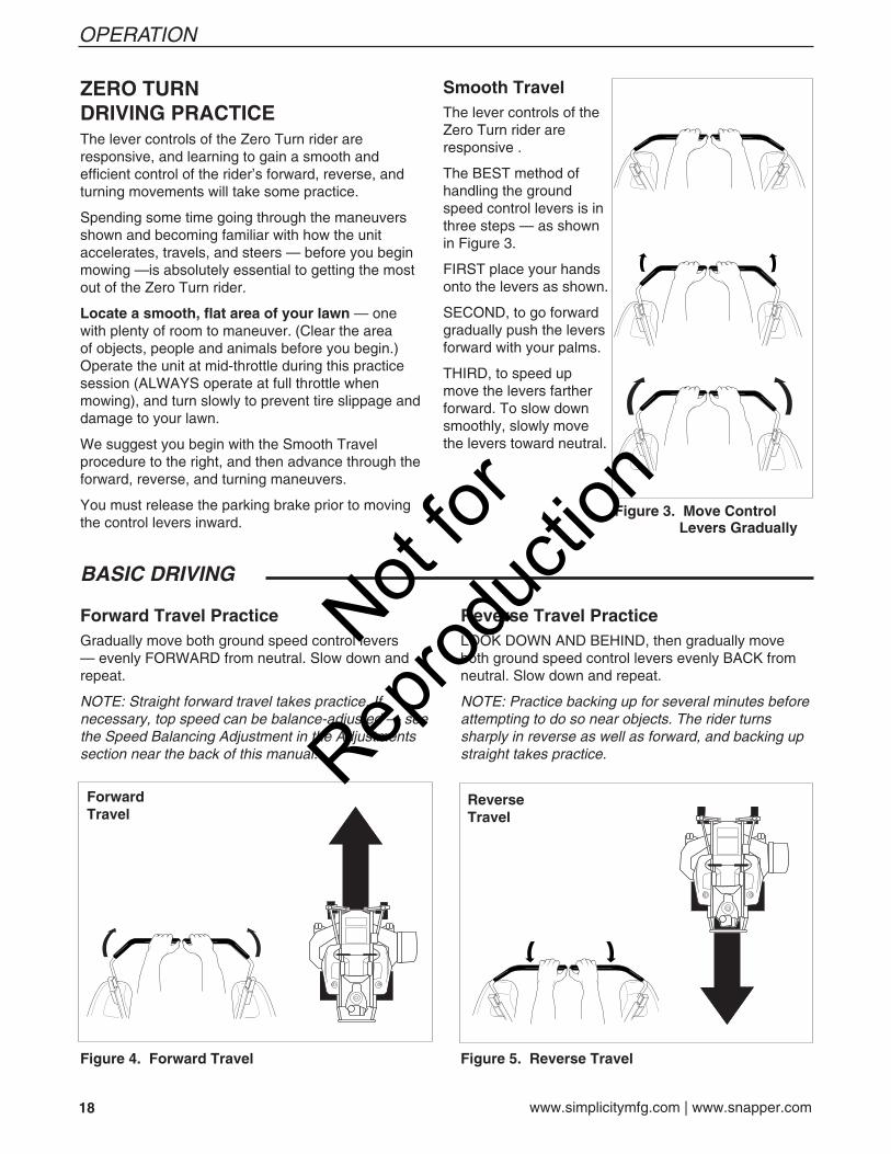
Figure 4. Forward Travel Figure 5. Reverse Travel
Smooth TravelThe lever controls of the Zero Turn rider are responsive .
The BEST method of handling the ground speed control levers is in three steps — as shown in Figure 3.
FIRST place your hands onto the levers as shown.
SECOND, to go forward gradually push the levers forward with your palms.
THIRD, to speed up move the levers farther forward. To slow down smoothly, slowly move the levers toward neutral.
Figure 3. Move Control Levers Gradually
ReverseTravel
ForwardTravel
Not for
Reprod
uctio
n
19
OPERATION
ADVANCED DRIVING
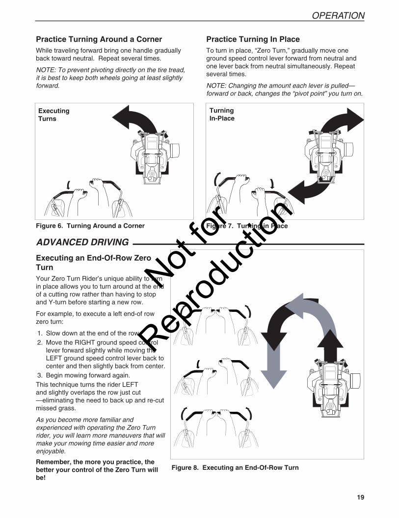
Executing an End-Of-Row Zero TurnYour Zero Turn Rider’s unique ability to turn in place allows you to turn around at the end of a cutting row rather than having to stop and Y-turn before starting a new row.
For example, to execute a left end-of row zero turn:
1. Slow down at the end of the row. 2. Move the RIGHT ground speed control
lever forward slightly while moving the LEFT ground speed control lever back to center and then slightly back from center.
3. Begin mowing forward again.This technique turns the rider LEFT and slightly overlaps the row just cut —eliminating the need to back up and re-cut missed grass.
As you become more familiar and experienced with operating the Zero Turn rider, you will learn more maneuvers that will make your mowing time easier and more enjoyable.
Remember, the more you practice, the better your control of the Zero Turn will be!
Practice Turning Around a CornerWhile traveling forward bring one handle gradually back toward neutral. Repeat several times.
NOTE: To prevent pivoting directly on the tire tread, it is best to keep both wheels going at least slightly forward.
ExecutingTurns
Figure 6. Turning Around a Corner Figure 7. Turning in Place
TurningIn-Place
Figure 8. Executing an End-Of-Row Turn
Practice Turning In PlaceTo turn in place, “Zero Turn,” gradually move one ground speed control lever forward from neutral and one lever back from neutral simultaneously. Repeat several times.
NOTE: Changing the amount each lever is pulled—forward or back, changes the “pivot point” you turn on.
Not for
Reprod
uctio
n
20 www.simplicitymfg.com | www.snapper.com
OPERATION
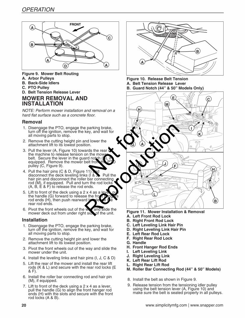
MOWER REMOVAL AND INSTALLATIONNOTE: Perform mower installation and removal on a hard flat surface such as a concrete floor.
Removal 1. Disengage the PTO, engage the parking brake,
turn off the ignition, remove the key, and wait for all moving parts to stop.
2. Remove the cutting height pin and lower the attachment lift to its lowest position.
3. Pull the lever (A, Figure 10) towards the rear of the machine to release tension on the mower belt. Secure the lever in the guard notch (B), if equipped. Remove the mower belt from the PTO pulley (C, Figure 9).
4. Pull the hair pins (C & D, Figure 11) and disconnect the deck leveling links (I & J). Pull the hair pin and disconnect the roller bar connecting rod (M), if equipped. Pull and turn the rod locks (A, B, E & F) to release the rod ends.
5. Lift to front of the deck using a 2 x 4 as a lever, pull the handle (G) forward to release the front hangers rod ends (H), then push rearward to release the rear rod ends.
6. Pivot the front wheels out of the way and slide the mower deck out from under right side of the unit.
Installation 1. Disengage the PTO, engage the parking brake,
turn off the ignition, remove the key, and wait for all moving parts to stop.
2. Remove the cutting height pin and lower the attachment lift to its lowest position.
3. Pivot the front wheels out of the way and slide the mower under the unit.
4. Install the leveling links and hair pins (I, J, C & D) 5. Lift the rear of the mower and install the rear lift
rods (K & L) and secure with the rear rod locks (E & F).
6. Install the roller bar connecting rod and hair pin (M), if equipped.
7. Lift to front of the deck using a 2 x 4 as a lever, pull the handle (G) to align the front hanger rod ends (H) with the slots and secure with the front rod locks (A & B).
Figure 9. Mower Belt RoutingA. Arbor PulleysB. Back-Side IdlersC. PTO PulleyD. Belt Tension Release Lever
A
AA
C
D
B
8. Install the belt as shown in Figure 9. 9. Release tension from the tensioning idler pulley
using the belt tension lever (A, Figure 10) and make sure the belt is seated properly in all pulleys.
Figure 10. Release Belt TensionA. Belt Tension Release LeverB. Guard Notch (44” & 50” Models Only)
A
B
Figure 11. Mower Installation & RemovalA. Left Front Rod LockB. Right Front Rod LockC. Left Leveling Link Hair PinD. Right Leveling Link Hair PinE. Left Rear Rod LockF. Right Rear Rod LockG. HandleH. Front Hanger Rod EndsI. Left Leveling LinkJ. Right Leveling LinkK. Left Rear Lift RodL. Right Rear Lift RodM. Roller Bar Connecting Rod (44” & 50” Models)
B
A
E
FJ
C
D
L
H
G
H
I
K
M
Not for
Reprod
uctio
n
21
OPERATION
Proper Cutting Height
Incremental Cutting
Cut Here On First Pass
Cut Here On Second Pass
MOWING RECOMMENDATIONSSeveral factors can affect how well your machine cuts grass, Following proper mowing recommendations can improve the performance and life of your machine.
Height of GrassOften cutting height is a matter of personal preference. Typically, you should mow the grass when it is is between three and five inches high. The proper cutting height range for a specific lawn will depend upon several factors, including the type of grass, the amount of rainfall, the prevailing temperature, and the lawn’s overall condition.
Cutting the grass too short causes weak, thin grass plants, which are easily damaged by dry periods and pests. Cutting too short is often more damaging than allowing the grass to be slightly higher.
Letting grass grow a bit longer—especially when it is hot and dry—reduces heat build-up, preserves needed moisture and protects the grass from heat damage and other problems. However, allowing grass to grow too high can cause thin turf and additional problems.
Cutting off too much at one time shocks the plant’s growth system and weakens the grass plants. A good rule of thumb is the 1/3 rule: to cut no more than one third of the grass height, and never more than 1 inch at a time.
The amount of grass you are able to cut in one pass is also effected by the type of mowing system you are using (for example, broadcasting with side discharge decks can process a much larger volume of grass than mulching does).
Tall Grass Requires Incremental CuttingFor extremely tall grass, set the cutting height at maximum for the first pass, and then reset it to the desired height and mow a second or third time.
Don’t cover the grass surface with a heavy layer of clippings. Consider using a grass collection system and starting a compost pile.
MOWINGBefore mowing, set the cutting height as described in the Troubleshooting, Adjustments & Service section.
1. Engage the parking brake. Make sure the PTO switch is disengaged and the motion control lever is in the NEUTRAL position.
2. Start the engine (see STARTING THE ENGINE).
3. Set the throttle to FULL.
4. Engage the PTO by pulling up on the PTO switch.
5. Begin mowing. See Mowing Recommendations section for tips on mowing patterns and lawn care. See Troubleshooting section for information on trouble shooting common cutting problems.
6. When finished, shut off the PTO.
7. Stop the engine (see STOPPING THE TRACTOR AND ENGINE).
Not for
Reprod
uctio
n
22 www.simplicitymfg.com | www.snapper.com
OPERATION
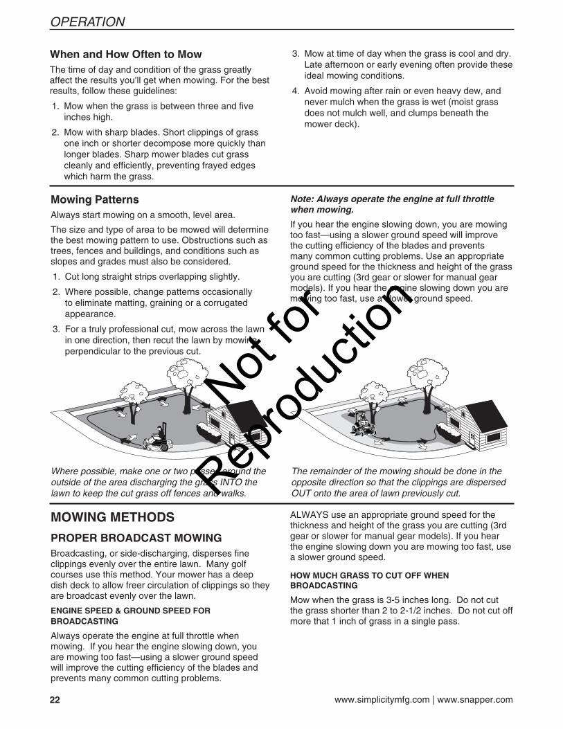
Mowing PatternsAlways start mowing on a smooth, level area.
The size and type of area to be mowed will determine the best mowing pattern to use. Obstructions such as trees, fences and buildings, and conditions such as slopes and grades must also be considered.
1. Cut long straight strips overlapping slightly.
2. Where possible, change patterns occasionally to eliminate matting, graining or a corrugated appearance.
3. For a truly professional cut, mow across the lawn in one direction, then recut the lawn by mowing perpendicular to the previous cut.
MOWING METHODS
PROPER BROADCAST MOWINGBroadcasting, or side-discharging, disperses fine clippings evenly over the entire lawn. Many golf courses use this method. Your mower has a deep dish deck to allow freer circulation of clippings so they are broadcast evenly over the lawn.
ENGINE SPEED & GROUND SPEED FOR BROADCASTING
Always operate the engine at full throttle when mowing. If you hear the engine slowing down, you are mowing too fast—using a slower ground speed will improve the cutting efficiency of the blades and prevents many common cutting problems.
Where possible, make one or two passes around the outside of the area discharging the grass INTO the lawn to keep the cut grass off fences and walks.
The remainder of the mowing should be done in the opposite direction so that the clippings are dispersed OUT onto the area of lawn previously cut.
When and How Often to MowThe time of day and condition of the grass greatly affect the results you’ll get when mowing. For the best results, follow these guidelines:
1. Mow when the grass is between three and five inches high.
2. Mow with sharp blades. Short clippings of grass one inch or shorter decompose more quickly than longer blades. Sharp mower blades cut grass cleanly and efficiently, preventing frayed edges which harm the grass.
3. Mow at time of day when the grass is cool and dry. Late afternoon or early evening often provide these ideal mowing conditions.
4. Avoid mowing after rain or even heavy dew, and never mulch when the grass is wet (moist grass does not mulch well, and clumps beneath the mower deck).
Note: Always operate the engine at full throttle when mowing.
If you hear the engine slowing down, you are mowing too fast—using a slower ground speed will improve the cutting efficiency of the blades and prevents many common cutting problems. Use an appropriate ground speed for the thickness and height of the grass you are cutting (3rd gear or slower for manual gear models). If you hear the engine slowing down you are mowing too fast, use a slower ground speed.
ALWAYS use an appropriate ground speed for the thickness and height of the grass you are cutting (3rd gear or slower for manual gear models). If you hear the engine slowing down you are mowing too fast, use a slower ground speed.
HOW MUCH GRASS TO CUT OFF WHEN BROADCASTING
Mow when the grass is 3-5 inches long. Do not cut the grass shorter than 2 to 2-1/2 inches. Do not cut off more that 1 inch of grass in a single pass.
Not for
Reprod
uctio
n
23
OPERATION
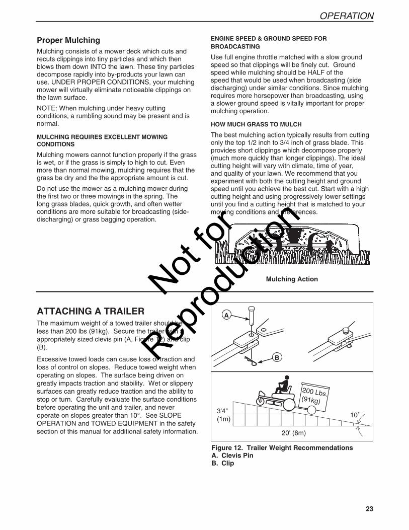
Figure 12. Trailer Weight RecommendationsA. Clevis PinB. Clip
ATTACHING A TRAILERThe maximum weight of a towed trailer should be less than 200 lbs (91kg). Secure the trailer with a appropriately sized clevis pin (A, Figure 12) and clip (B).
Excessive towed loads can cause loss of traction and loss of control on slopes. Reduce towed weight when operating on slopes. The surface being driven on greatly impacts traction and stability. Wet or slippery surfaces can greatly reduce traction and the ability to stop or turn. Carefully evaluate the surface conditions before operating the unit and trailer, and never operate on slopes greater than 10°. See SLOPE OPERATION and TOWED EQUIPMENT in the safety section of this manual for additional safety information.
A
B
Proper MulchingMulching consists of a mower deck which cuts and recuts clippings into tiny particles and which then blows them down INTO the lawn. These tiny particles decompose rapidly into by-products your lawn can use. UNDER PROPER CONDITIONS, your mulching mower will virtually eliminate noticeable clippings on the lawn surface.
NOTE: When mulching under heavy cutting conditions, a rumbling sound may be present and is normal.
MULCHING REQUIRES EXCELLENT MOWING CONDITIONS
Mulching mowers cannot function properly if the grass is wet, or if the grass is simply to high to cut. Even more than normal mowing, mulching requires that the grass be dry and the the appropriate amount is cut.
Do not use the mower as a mulching mower during the first two or three mowings in the spring. The long grass blades, quick growth, and often wetter conditions are more suitable for broadcasting (side-discharging) or grass bagging operation.
Mulching Action
ENGINE SPEED & GROUND SPEED FOR BROADCASTING
Use full engine throttle matched with a slow ground speed so that clippings will be finely cut. Ground speed while mulching should be HALF of the speed that would be used when broadcasting (side discharging) under similar conditions. Since mulching requires more horsepower than broadcasting, using a slower ground speed is vitally important for proper mulching operation.
HOW MUCH GRASS TO MULCH
The best mulching action typically results from cutting only the top 1/2 inch to 3/4 inch of grass blade. This provides short clippings which decompose properly (much more quickly than longer clippings). The ideal cutting height will vary with climate, time of year, and quality of your lawn. We recommend that you experiment with both the cutting height and ground speed until you achieve the best cut. Start with a high cutting height and using progressively lower settings until you find a cutting height that is matched to your mowing conditions and preferences.
Not for
Reprod
uctio
n

24 www.simplicitymfg.com | www.snapper.com
MAINTENANCE
MAINTENANCE SCHEDULE & PROCEDURESThe following schedule should be followed for normal care of your rider and mower. You will need to keep a record of your operating time. Determining operating time is easily accomplished by observing the elapsed time recorded by the hour meter.
MOWER MAINTENANCE
Before Each Use
Check Safety Interlock System
Check Rider Brakes
Check Transmission Oil Level
Every 5 Hours
Check Rider / Mower for loose hardware
Every 25 Hours
Lubricate Rider & Mower*
Check Tire Pressure
Clean Deck & Check / Replace Mower Blades*
Every 100 Hours
Check / Adjust PTO Clutch
Clean Battery & Cables
Check Mower Blade Stopping Time
Every 250 Hours
Change Transmission Oil Filter
* More often in hot (over 85° F: 30° C) weather or dusty operating conditions.
ENGINE MAINTENANCE
Before Each Use
Check Engine Oil Level
Every 25 Hours
Check / Clean Engine Cooling Fins*
Every 50 Hours
Check / Clean Spark Arrester**
Refer to Engine Owner’s Manual
Check / Change Engine Air Filter
Change Engine Oil & Filter
Inspect Spark Plug(s)
Check / Replace Fuel Filter
* More often in hot (over 85° F: 30° C) weather or dusty operating conditions.
** If equipped. Replace if damaged.
MAINTENANCE SCHEDULE
Not for
Reprod
uctio
n
25
MAINTENANCE
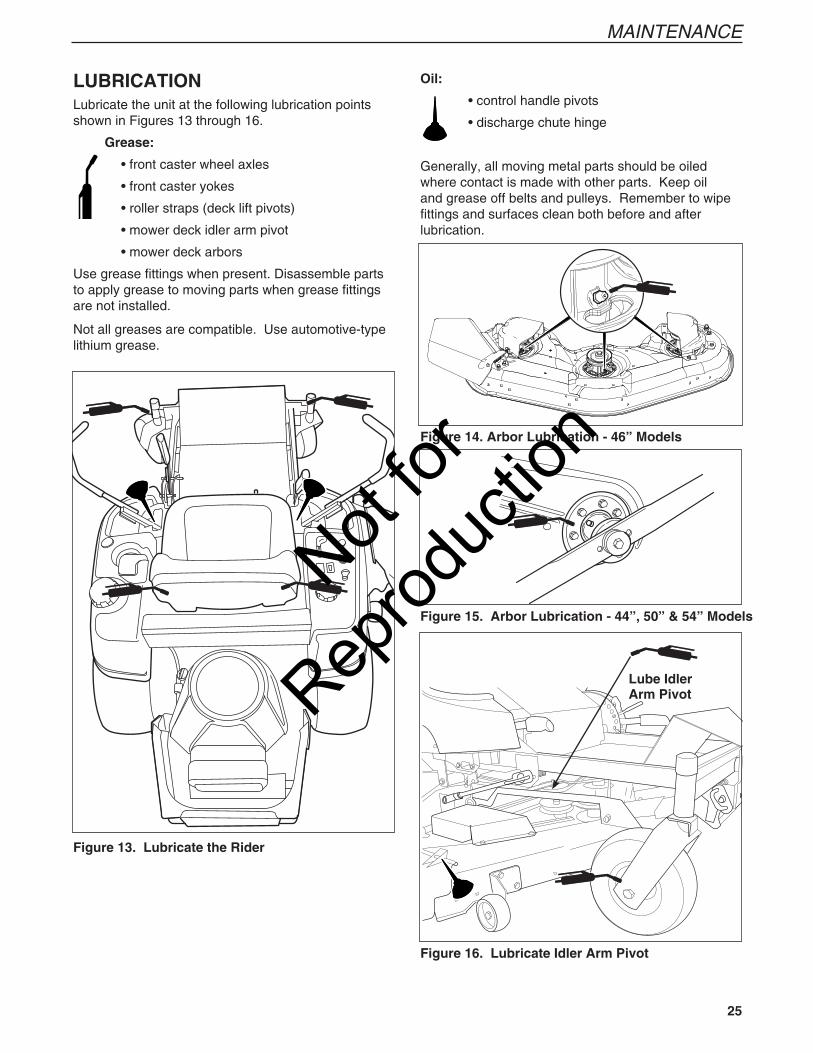
LUBRICATIONLubricate the unit at the following lubrication points shown in Figures 13 through 16.
Grease:
• front caster wheel axles
• front caster yokes
• roller straps (deck lift pivots)
• mower deck idler arm pivot
• mower deck arbors
Use grease fittings when present. Disassemble parts to apply grease to moving parts when grease fittings are not installed.
Not all greases are compatible. Use automotive-type lithium grease.
Oil:
• control handle pivots
• discharge chute hinge
Generally, all moving metal parts should be oiled where contact is made with other parts. Keep oil and grease off belts and pulleys. Remember to wipe fittings and surfaces clean both before and after lubrication.
Figure 13. Lubricate the Rider
Lube Idler Arm Pivot
Figure 16. Lubricate Idler Arm Pivot
Figure 15. Arbor Lubrication - 44”, 50” & 54” Models
Figure 14. Arbor Lubrication - 46” Models
Not for
Reprod
uctio
n
26 www.simplicitymfg.com | www.snapper.com
MAINTENANCE
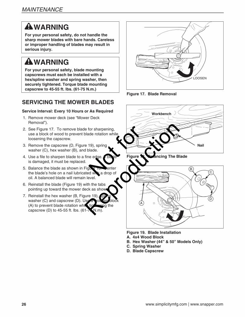
SERVICING THE MOWER BLADES
Service Interval: Every 10 Hours or As Required
1. Remove mower deck (see “Mower Deck Removal”).
2. See Figure 17. To remove blade for sharpening, use a block of wood to prevent blade rotation while loosening the capscrew.
3. Remove the capscrew (D, Figure 19), spring washer (C), hex washer (B), and blade.
4. Use a file to sharpen blade to a fine edge. If blade is damaged, it must be replaced.
5. Balance the blade as shown in Figure 18. Center the blade’s hole on a nail lubricated with a drop of oil. A balanced blade will remain level.
6. Reinstall the blade (Figure 19) with the tabs pointing up toward the mower deck as shown.
7. Reinstall the hex washer (B, Figure 19), spring washer (C) and capscrew (D). Use a wooden block (A) to prevent blade rotation while tightening the capscrew (D) to 45-55 ft. lbs. (61-75 N.m).
WARNINGFor your personal safety, do not handle the sharp mower blades with bare hands. Careless or improper handling of blades may result in serious injury.
WARNINGFor your personal safety, blade mounting capscrews must each be installed with a hex/spline washer and spring washer, then securely tightened. Torque blade mounting capscrew to 45-55 ft. lbs. (61-75 N.m.)
Figure 18. Balancing The Blade
Workbench
Nail
Figure 17. Blade Removal
AD
CB
Figure 19. Blade InstallationA. 4x4 Wood BlockB. Hex Washer (44” & 50” Models Only)C. Spring WasherD. Blade Capscrew
Not for
Reprod
uctio
n
27
MAINTENANCE
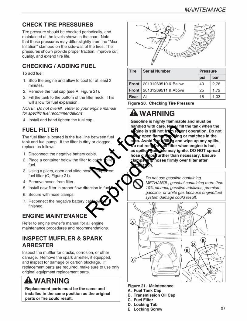
CHECK TIRE PRESSURESTire pressure should be checked periodically, and maintained at the levels shown in the chart. Note that these pressures may differ slightly from the “Max Inflation” stamped on the side-wall of the tires. The pressures shown provide proper traction, improve cut quality, and extend tire life.
CHECKING / ADDING FUELTo add fuel:
1. Stop the engine and allow to cool for at least 3 minutes.
2. Remove the fuel cap (see A, Figure 21).
3. Fill the tank to the bottom of the filler neck. This will allow for fuel expansion.
NOTE: Do not overfill. Refer to your engine manual for specific fuel recommendations.
4. Install and hand tighten the fuel cap.
FUEL FILTERThe fuel filter is located in the fuel line between fuel tank and fuel pump. If the filter is dirty or clogged, replace as follows:
1. Disconnect the negative battery cable.
2. Place a container below the filter to catch spilled fuel.
3. Using a pliers, open and slide hose clamps from fuel filter (C, Figure 21).
4. Remove hoses from filter.
5. Install new filter in proper flow direction in fuel line.
6. Secure with hose clamps.
7. Reconnect the negative battery cable when finished.
ENGINE MAINTENANCERefer to engine owner’s manual for all engine maintenance procedures and recommendations.
INSPECT MUFFLER & SPARK ARRESTERInspect the muffler for cracks, corrosion, or other damage. Remove the spark arrester, if equipped, and inspect for damage or carbon blockage. If replacement parts are required, make sure to use only original equipment replacement parts.
WARNINGGasoline is highly flammable and must be handled with care. Never fill the tank when the engine is still hot from recent operation. Do not allow open flame, smoking or matches in the area. Avoid over-filling and wipe up any spills.Do not remove fuel filter when engine is hot, as spilled gasoline may ignite. DO NOT spread hose clamps further than necessary. Ensure clamps grip hoses firmly over filter after installation.
Do not use gasoline containing METHANOL, gasohol containing more than 10% ethanol, gasoline additives, premium gasoline, or white gas because engine/fuel system damage could result.
Figure 20. Checking Tire Pressure
Figure 21. MaintenanceA. Fuel Tank CapB. Transmission Oil CapC. Fuel FilterD. Locking TabE. Locking Screw
B
A
C
D
E
B
WARNINGReplacement parts must be the same and installed in the same position as the original parts or fire could result.
Tire Serial Number Pressure
psi bar
Front 20131269510 & Below 40 2,76
Front 20131269511 & Above 25 1,72
Rear All 15 1,03
Not for
Reprod
uctio
n
28 www.simplicitymfg.com | www.snapper.com
MAINTENANCE
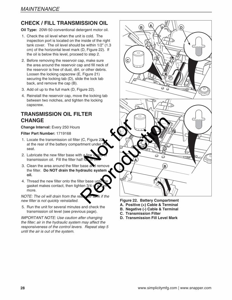
CHECK / FILL TRANSMISSION OILOil Type: 20W-50 conventional detergent motor oil.
1. Check the oil level when the unit is cold. The inspection port is located on the inside of the right tank cover. The oil level should be within 1/2” (1.3 cm) of the horizontal level mark (D, Figure 22). If the oil is below this level, proceed to step 2.
2. Before removing the reservoir cap, make sure the area around the reservoir cap and fill neck of the reservoir is free of dust, dirt, or other debris. Loosen the locking capscrew (E, Figure 21) securing the locking tab (D), slide the lock tab back, and remove the cap (B).
3. Add oil up to the full mark (D, Figure 22).
4. Reinstall the reservoir cap, move the locking tab between two notches, and tighten the locking capscrew.
TRANSMISSION OIL FILTER CHANGEChange Interval: Every 250 Hours
Filter Part Number: 1719168
1. Locate the transmission oil filter (C, Figure 22) at the rear of the battery compartment under the seat.
2. Lubricate the new filter base with a few drops of transmission oil. Fill the filter half full of oil.
3. Clean the area around the filter base and remove the filter. Do NOT drain the hydraulic system oil.
4. Thread the new filter onto the filter base until the gasket makes contact, then tighten 3/4 of a turn more.
NOTE: The oil will drain from the reservoir tank if the new filter is not quickly reinstalled.
5. Run the unit for several minutes and check the transmission oil level (see previous page).
IMPORTANT NOTE: Use caution after changing the filter; air in the hydraulic system may affect the responsiveness of the control levers. Repeat step 5 until the air is out of the system.
Figure 22. Battery CompartmentA. Positive (+) Cable & TerminalB. Negative (-) Cable & TerminalC. Transmission FilterD. Transmission Fill Level Mark
C
B A D
A
BNot for
Reprod
uctio
n

29
MAINTENANCE
WARNINGBe careful when handling the battery. Avoid spilling electrolyte. Keep flames and sparks away from the battery.When removing or installing battery cables, disconnect the negative cable FIRST and reconnect it LAST. If not done in this order, the positive terminal can be shorted to the frame by a tool.
BATTERY MAINTENANCE Cleaning the Battery and Cables 1. Disconnect the cables from the battery, negative
cable first (B, Figure 22).
2. Clean the battery terminals and cable ends with a wire brush until shiny.
3. Reinstall the battery and reattach the battery cables, positive cable first (see A, Figure 22)
4. Coat the cable ends and battery terminals with petroleum jelly or non-conducting grease.
BATTERY CHARGINGA dead battery or one too weak to start the engine may be the result of a defect in the charging system or other electrical component. If there is any doubt about the cause of the problem, see your dealer. If you need to replace the battery, follow the steps under Cleaning the Battery & Cables in the Regular Maintenance Section.
To charge the battery, follow the instructions provided by the battery charger manufacturer as well as all warnings included in the safety rules sections of this book. Charge the battery until fully charged. Do not charge at a rate higher than 10 amps.
WARNINGKeep open flames and sparks away from the battery; the gasses coming from it are highly explosive. Ventilate the battery well during charging.
WARNINGNever store the unit (with fuel) in an enclosed, poorly ventilated structure. Fuel vapors can travel to an ignition source (such as a furnace, water heater, etc.) and cause an explosion.Fuel vapor is also toxic to humans and animals.
STORAGEBefore you store your unit for the off-season, read the Maintenance and Storage instructions in the Safety Rules section, then perform the following steps:
• Disengage the PTO, set the parking brake, & remove the key.
• Perform engine maintenance and storage measures listed in the engine owner’s manual. This includes draining the fuel system, or adding stabilizer to the fuel (do not store a fueled unit in an enclosed structure - see warning).
• Battery life will be increased if it is removed, put in a cool, dry place and fully charged about once a month. If the battery is left in the unit, disconnect the negative cable.
Before starting the unit after it has been stored:
• Check all fluid levels. Check all maintenance items.
• Perform all recommended checks and procedures found in the engine owner’s manual.
• Allow the engine to warm up for several minutes before use.
Not for
Reprod
uctio
n
30 www.simplicitymfg.com | www.snapper.com
MAINTENANCE
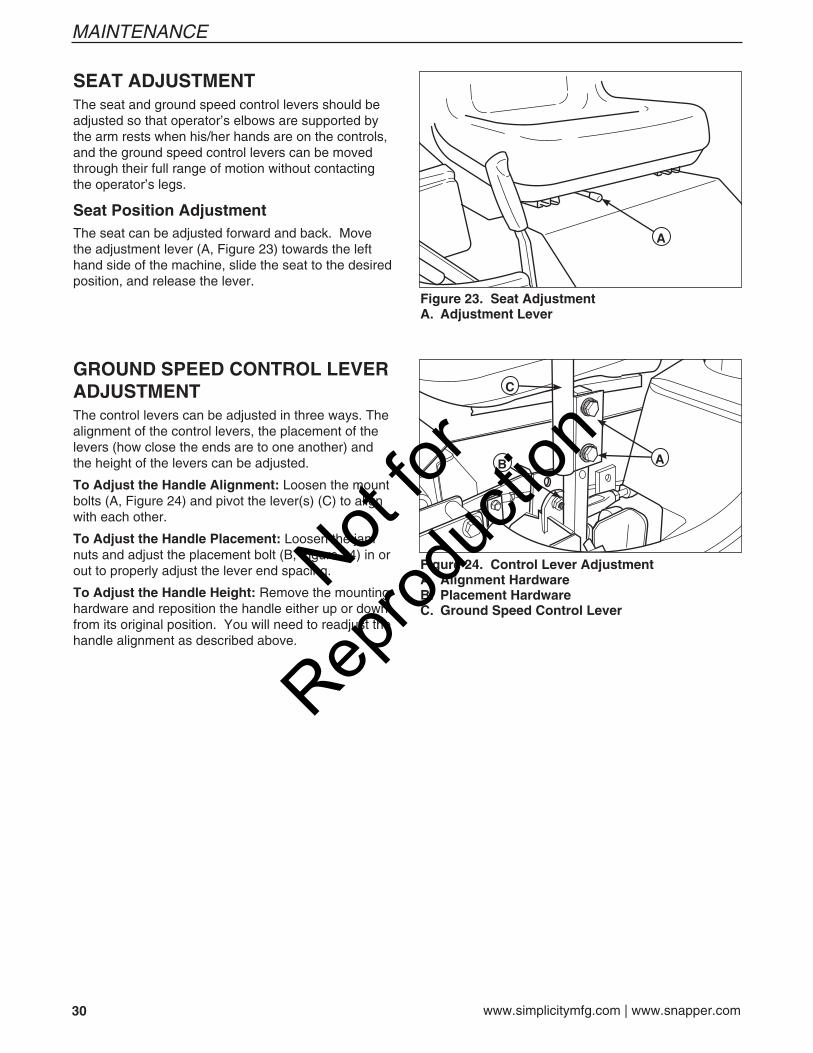
SEAT ADJUSTMENTThe seat and ground speed control levers should be adjusted so that operator’s elbows are supported by the arm rests when his/her hands are on the controls, and the ground speed control levers can be moved through their full range of motion without contacting the operator’s legs.
Seat Position AdjustmentThe seat can be adjusted forward and back. Move the adjustment lever (A, Figure 23) towards the left hand side of the machine, slide the seat to the desired position, and release the lever.
Figure 24. Control Lever AdjustmentA. Alignment HardwareB. Placement HardwareC. Ground Speed Control Lever
B
C
A
Figure 23. Seat AdjustmentA. Adjustment Lever
A
GROUND SPEED CONTROL LEVER ADJUSTMENTThe control levers can be adjusted in three ways. The alignment of the control levers, the placement of the levers (how close the ends are to one another) and the height of the levers can be adjusted.
To Adjust the Handle Alignment: Loosen the mount bolts (A, Figure 24) and pivot the lever(s) (C) to align with each other.
To Adjust the Handle Placement: Loosen the jam nuts and adjust the placement bolt (B, Figure 24) in or out to properly adjust the lever end spacing.
To Adjust the Handle Height: Remove the mounting hardware and reposition the handle either up or down from its original position. You will need to readjust the handle alignment as described above.
Not for
Reprod
uctio
n
31
MAINTENANCE
Figure 26. Cutting Height AdjustmentA. Cutting Height Adjustment PinB. Deck Lift / Cutting Height LeverC. Transport Release Lever
BC
A
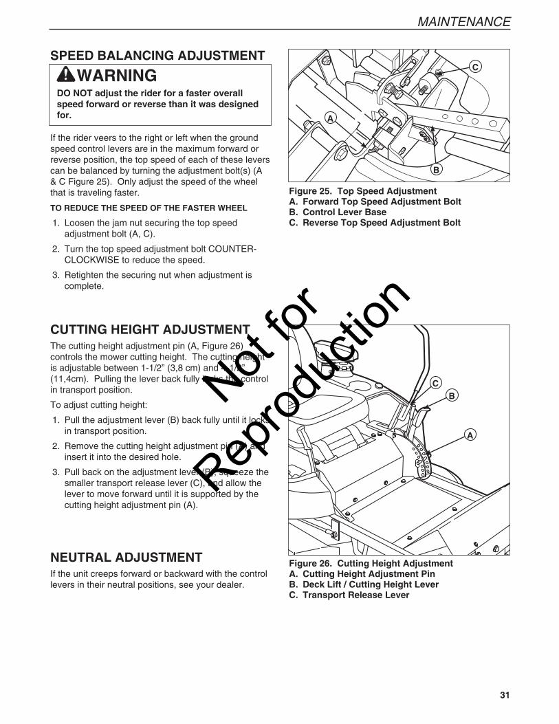
CUTTING HEIGHT ADJUSTMENTThe cutting height adjustment pin (A, Figure 26) controls the mower cutting height. The cutting height is adjustable between 1-1/2” (3,8 cm) and 4-1/2” (11,4cm). Pulling the lever back fully locks the control in transport position.
To adjust cutting height:
1. Pull the adjustment lever (B) back fully until it locks in transport position.
2. Remove the cutting height adjustment pin (A) and insert it into the desired hole.
3. Pull back on the adjustment lever (B), squeeze the smaller transport release lever (C), and allow the lever to move forward until it is supported by the cutting height adjustment pin (A).
NEUTRAL ADJUSTMENTIf the unit creeps forward or backward with the control levers in their neutral positions, see your dealer.
SPEED BALANCING ADJUSTMENT
If the rider veers to the right or left when the ground speed control levers are in the maximum forward or reverse position, the top speed of each of these levers can be balanced by turning the adjustment bolt(s) (A & C Figure 25). Only adjust the speed of the wheel that is traveling faster.
TO REDUCE THE SPEED OF THE FASTER WHEEL
1. Loosen the jam nut securing the top speed adjustment bolt (A, C).
2. Turn the top speed adjustment bolt COUNTER-CLOCKWISE to reduce the speed.
3. Retighten the securing nut when adjustment is complete.
WARNINGDO NOT adjust the rider for a faster overall speed forward or reverse than it was designed for.
Figure 25. Top Speed AdjustmentA. Forward Top Speed Adjustment BoltB. Control Lever BaseC. Reverse Top Speed Adjustment Bolt
A
B
C
Not for
Reprod
uctio
n
32 www.simplicitymfg.com | www.snapper.com
MAINTENANCE
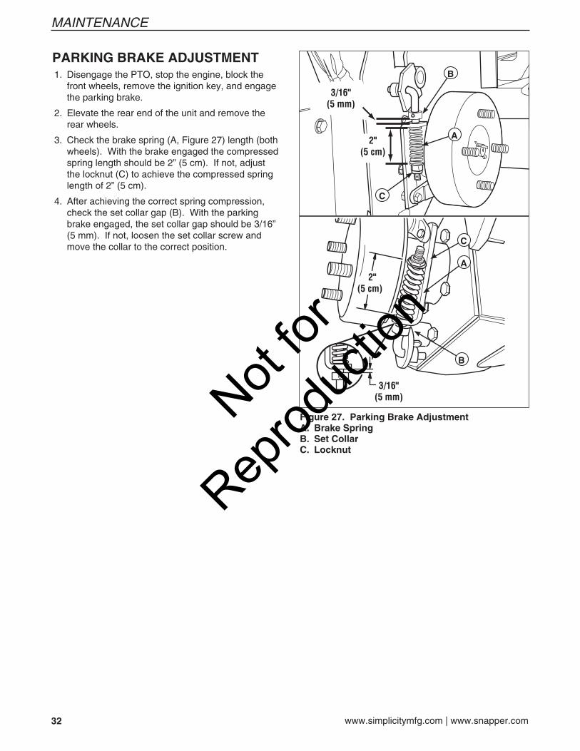
Figure 27. Parking Brake AdjustmentA. Brake SpringB. Set CollarC. Locknut
PARKING BRAKE ADJUSTMENT 1. Disengage the PTO, stop the engine, block the
front wheels, remove the ignition key, and engage the parking brake.
2. Elevate the rear end of the unit and remove the rear wheels.
3. Check the brake spring (A, Figure 27) length (both wheels). With the brake engaged the compressed spring length should be 2” (5 cm). If not, adjust the locknut (C) to achieve the compressed spring length of 2” (5 cm).
4. After achieving the correct spring compression, check the set collar gap (B). With the parking brake engaged, the set collar gap should be 3/16” (5 mm). If not, loosen the set collar screw and move the collar to the correct position.
A
B
C
C
A
B
Not for
Reprod
uctio
n
33
MAINTENANCE
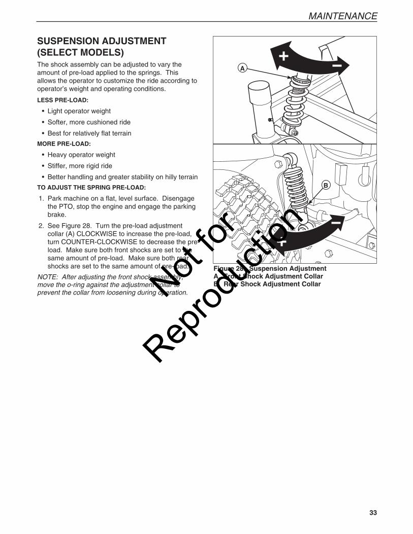
SUSPENSION ADJUSTMENT(SELECT MODELS)The shock assembly can be adjusted to vary the amount of pre-load applied to the springs. This allows the operator to customize the ride according to operator’s weight and operating conditions.
LESS PRE-LOAD:
• Light operator weight
• Softer, more cushioned ride
• Best for relatively flat terrain
MORE PRE-LOAD:
• Heavy operator weight
• Stiffer, more rigid ride
• Better handling and greater stability on hilly terrain
TO ADJUST THE SPRING PRE-LOAD:
1. Park machine on a flat, level surface. Disengage the PTO, stop the engine and engage the parking brake.
2. See Figure 28. Turn the pre-load adjustment collar (A) CLOCKWISE to increase the pre-load, turn COUNTER-CLOCKWISE to decrease the pre-load. Make sure both front shocks are set to the same amount of pre-load. Make sure both rear shocks are set to the same amount of pre-load.
NOTE: After adjusting the front shock assembly, move the o-ring against the adjustment collar to prevent the collar from loosening during operation.
Figure 28. Suspension AdjustmentA. Front Shock Adjustment CollarB. Rear Shock Adjustment Collar
A
B
Not for
Reprod
uctio
n
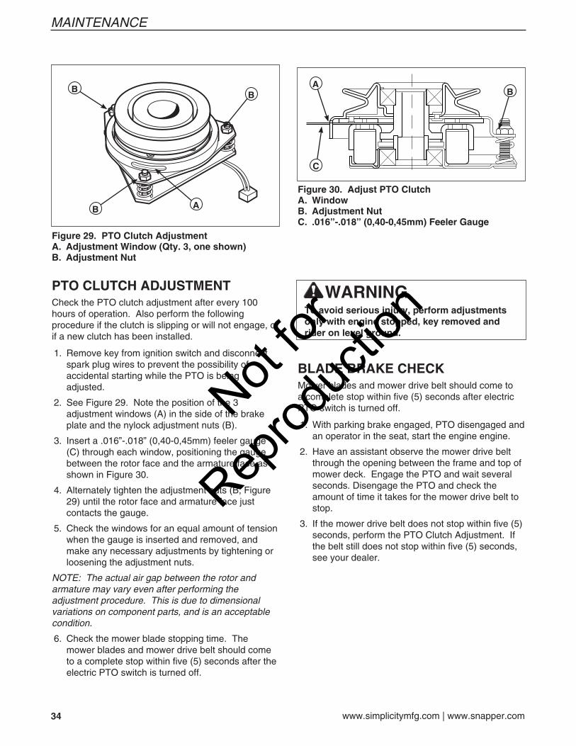
34 www.simplicitymfg.com | www.snapper.com
MAINTENANCE
WARNINGTo avoid serious injury, perform adjustments only with engine stopped, key removed and rider on level ground.
AB
BB
Figure 29. PTO Clutch AdjustmentA. Adjustment Window (Qty. 3, one shown)B. Adjustment Nut
BA
C
Figure 30. Adjust PTO ClutchA. WindowB. Adjustment NutC. .016”-.018” (0,40-0,45mm) Feeler Gauge
PTO CLUTCH ADJUSTMENTCheck the PTO clutch adjustment after every 100 hours of operation. Also perform the following procedure if the clutch is slipping or will not engage, or if a new clutch has been installed.
1. Remove key from ignition switch and disconnect spark plug wires to prevent the possibility of accidental starting while the PTO is being adjusted.
2. See Figure 29. Note the position of the 3 adjustment windows (A) in the side of the brake plate and the nylock adjustment nuts (B).
3. Insert a .016”-.018” (0,40-0,45mm) feeler gauge (C) through each window, positioning the gauge between the rotor face and the armature face as shown in Figure 30.
4. Alternately tighten the adjustment nuts (B, Figure 29) until the rotor face and armature face just contacts the gauge.
5. Check the windows for an equal amount of tension when the gauge is inserted and removed, and make any necessary adjustments by tightening or loosening the adjustment nuts.
NOTE: The actual air gap between the rotor and armature may vary even after performing the adjustment procedure. This is due to dimensional variations on component parts, and is an acceptable condition.
6. Check the mower blade stopping time. The mower blades and mower drive belt should come to a complete stop within five (5) seconds after the electric PTO switch is turned off.
BLADE BRAKE CHECKMower blades and mower drive belt should come to a complete stop within five (5) seconds after electric PTO switch is turned off.
1. With parking brake engaged, PTO disengaged and an operator in the seat, start the engine engine.
2. Have an assistant observe the mower drive belt through the opening between the frame and top of mower deck. Engage the PTO and wait several seconds. Disengage the PTO and check the amount of time it takes for the mower drive belt to stop.
3. If the mower drive belt does not stop within five (5) seconds, perform the PTO Clutch Adjustment. If the belt still does not stop within five (5) seconds, see your dealer.
Not for
Reprod
uctio
n
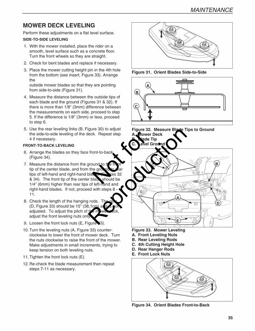
35
MAINTENANCE
MOWER DECK LEVELINGPerform these adjustments on a flat level surface.
SIDE-TO-SIDE LEVELING
1. With the mower installed, place the rider on a smooth, level surface such as a concrete floor. Turn the front wheels so they are straight.
2. Check for bent blades and replace if necessary.
3. Place the mower cutting height pin in the 4th hole from the bottom (see insert, Figure 33). Arrange the outside mower blades so that they are pointing from side-to-side (Figure 31).
4. Measure the distance between the outside tips of each blade and the ground (Figures 31 & 32). If there is more than 1/8” (3mm) difference between the measurements on each side, proceed to step 5. If the difference is 1/8” (3mm) or less, proceed to step 6.
5. Use the rear leveling links (B, Figure 30) to adjust the side-to-side leveling of the deck. Repeat step 4 if necessary.
FRONT-TO-BACK LEVELING
6. Arrange the blades so they face front-to-back (Figure 34).
7. Measure the distance from the ground to the front tip of the center blade, and from the ground to rear tips of left-hand and right-hand blades (Figures 32 & 34). The front tip of the center blade should be 1/4” (6mm) higher than rear tips of left-hand and right-hand blades. If not, proceed with steps 8 - 11.
8. Check the length of the hanging rods. The rear (D, Figure 33) should be 15” (38,1cm) and is not adjusted. To adjust the pitch of the mower deck, adjust the front leveling nuts only.
9. Loosen the front lock nuts (E, Figure 33).
10. Turn the leveling nuts (A, Figure 33) counter- clockwise to lower the front of mower deck. Turn the nuts clockwise to raise the front of the mower. Make adjustments in small increments, trying to keep tension on both leveling nuts.
11. Tighten the front lock nuts (E).
12. Re-check the blade measurement then repeat steps 7-11 as necessary.
Figure 34. Orient Blades Front-to-Back
Figure 31. Orient Blades Side-to-Side
Figure 32. Measure Blade Tips to GroundA. Mower DeckB. Blade TipC. Level Ground
A
B
C
Figure 33. Mower LevelingA. Front Leveling NutsB. Rear Leveling RodsC. 4th Cutting Height HoleD. Rear Hanger RodsE. Front Lock Nuts
B
D
C
A
E
Not for
Reprod
uctio
n
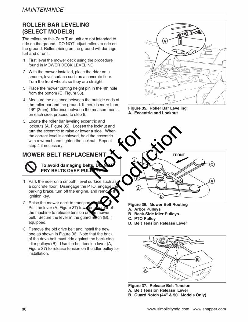
36 www.simplicitymfg.com | www.snapper.com
MAINTENANCE
ROLLER BAR LEVELING (SELECT MODELS)The rollers on this Zero Turn unit are not intended to ride on the ground. DO NOT adjust rollers to ride on the ground. Rollers riding on the ground will damage turf and or unit.
1. First level the mower deck using the procedure found in MOWER DECK LEVELING.
2. With the mower installed, place the rider on a smooth, level surface such as a concrete floor. Turn the front wheels so they are straight.
3. Place the mower cutting height pin in the 4th hole from the bottom (C, Figure 36).
4. Measure the distance between the outside ends of the roller bar and the ground. If there is more than 1/8” (3mm) difference between the measurements on each side, proceed to step 5.
5. Locate the roller bar leveling eccentric and locknuts (A, Figure 35). Loosen the locknut and turn the eccentric to raise or lower a side. When the correct level is achieved, hold the eccentric with a wrench and tighten the locknut. Repeat step 4 if necessary.
Figure 35. Roller Bar LevelingA. Eccentric and Locknut
A
MOWER BELT REPLACEMENT
1. Park the rider on a smooth, level surface such as a concrete floor. Disengage the PTO, engage the parking brake, turn off the engine, and remove the ignition key.
2. Raise the mower deck to transport position. Pull the lever (A, Figure 37) towards the rear of the machine to release tension on the mower belt. Secure the lever in the guard notch (B), if equipped.
3. Remove the old drive belt and install the new one as shown in Figure 36. Note that the back of the drive belt must ride against the back-side idler pulleys (B). Use the belt tension lever (A, Figure 37) to release tension on the idler pulley for installation.
To avoid damaging belts, DO NOT PRY BELTS OVER PULLEYS.
Figure 36. Mower Belt RoutingA. Arbor PulleysB. Back-Side Idler PulleysC. PTO PulleyD. Belt Tension Release Lever
A
A
A
C
D
B
Figure 37. Release Belt TensionA. Belt Tension Release LeverB. Guard Notch (44” & 50” Models Only)
A
B
Not for
Reprod
uctio
n
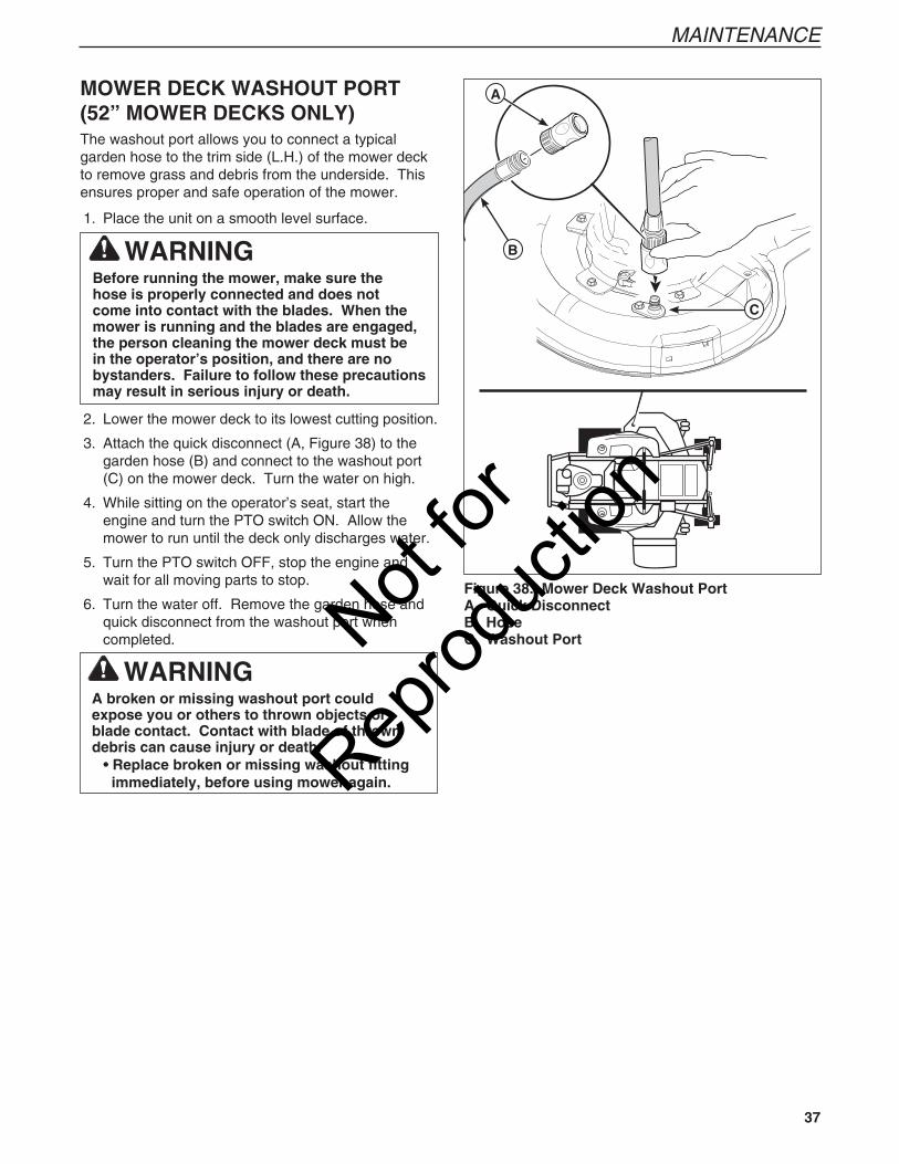
37
MAINTENANCE
MOWER DECK WASHOUT PORT (52” MOWER DECKS ONLY)The washout port allows you to connect a typical garden hose to the trim side (L.H.) of the mower deck to remove grass and debris from the underside. This ensures proper and safe operation of the mower.
1. Place the unit on a smooth level surface.
2. Lower the mower deck to its lowest cutting position.
3. Attach the quick disconnect (A, Figure 38) to the garden hose (B) and connect to the washout port (C) on the mower deck. Turn the water on high.
4. While sitting on the operator’s seat, start the engine and turn the PTO switch ON. Allow the mower to run until the deck only discharges water.
5. Turn the PTO switch OFF, stop the engine and wait for all moving parts to stop.
6. Turn the water off. Remove the garden hose and quick disconnect from the washout port when completed.
WARNINGBefore running the mower, make sure the hose is properly connected and does not come into contact with the blades. When the mower is running and the blades are engaged, the person cleaning the mower deck must be in the operator’s position, and there are no bystanders. Failure to follow these precautions may result in serious injury or death.
WARNINGA broken or missing washout port could expose you or others to thrown objects or blade contact. Contact with blade of thrown debris can cause injury or death.
• Replace broken or missing washout fitting immediately, before using mower again.
Figure 38. Mower Deck Washout PortA. Quick DisconnectB. HoseC. Washout Port
B
A
C
Not for
Reprod
uctio
n
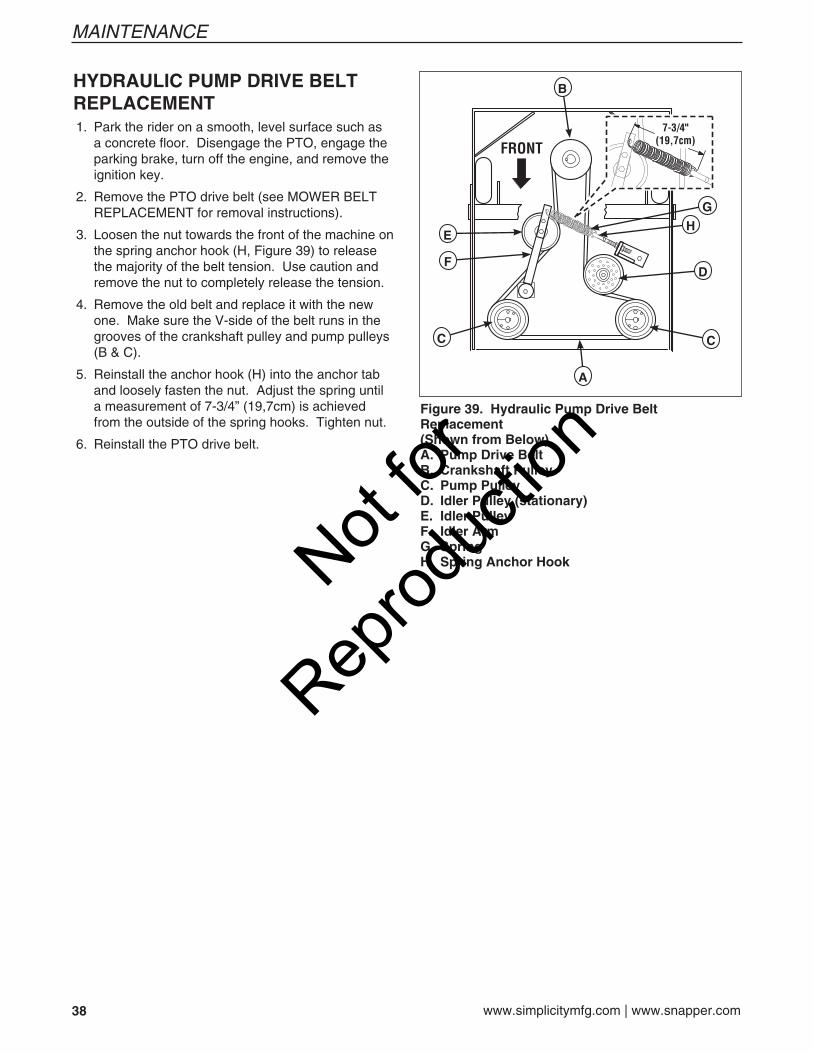
38 www.simplicitymfg.com | www.snapper.com
MAINTENANCE
HYDRAULIC PUMP DRIVE BELT REPLACEMENT 1. Park the rider on a smooth, level surface such as
a concrete floor. Disengage the PTO, engage the parking brake, turn off the engine, and remove the ignition key.
2. Remove the PTO drive belt (see MOWER BELT REPLACEMENT for removal instructions).
3. Loosen the nut towards the front of the machine on the spring anchor hook (H, Figure 39) to release the majority of the belt tension. Use caution and remove the nut to completely release the tension.
4. Remove the old belt and replace it with the new one. Make sure the V-side of the belt runs in the grooves of the crankshaft pulley and pump pulleys (B & C).
5. Reinstall the anchor hook (H) into the anchor tab and loosely fasten the nut. Adjust the spring until a measurement of 7-3/4” (19,7cm) is achieved from the outside of the spring hooks. Tighten nut.
6. Reinstall the PTO drive belt.
Figure 39. Hydraulic Pump Drive Belt Replacement(Shown from Below)A. Pump Drive BeltB. Crankshaft PulleyC. Pump PulleyD. Idler Pulley (stationary)E. Idler PulleyF. Idler ArmG. SpringH. Spring Anchor Hook
B
E
F
A
C C
H
D
G
Not for
Reprod
uctio
n

39
TROUBLESHOOTING
TROUBLESHOOTINGWhile normal care and regular maintenance will extend the life of your equipment, prolonged or constant use may eventually require that service be performed to allow it to continue operating properly.
The troubleshooting guide below lists the most common problems, their causes and remedies.
See the information on the following pages for instructions on how to perform most of these minor adjustments and service repairs yourself. If you prefer, all of these procedures can be performed for you by your local authorized dealer.
WARNINGTo avoid serious injury, perform maintenance on the tractor or mower only when the engine is stopped and the parking brake engaged.
Always remove the ignition key, disconnect the spark plug wire and fasten it away from the plug before beginning the maintenance, to prevent accidental starting of the engine.
TROUBLESHOOTING THE RIDER PROBLEM CAUSE REMEDY
Engine will not turnover or start. 1. Parking brake not engaged. 1. Engage parking brake. 2. PTO (electric clutch) switch 2. Place in OFF position. in ON position. 3. Out of fuel. 3. If engine is hot, allow it to cool, then refill the fuel tank. 4. Engine flooded. 4. Move choke control to closed position. 5. Fuse blown. 5. Replace fuse. 6. Battery terminals require 6. Clean the battery terminals cleaning. 7. Battery discharged or dead. 7. Recharge or replace. 8. Wiring loose or broken. 8. Visually check wiring & replace broken or frayed wires. Tighten loose connections. 9. Solenoid or starter motor faulty. 9. Repair or replace. See authorized dealer 10. Safety interlock switch 10. Replace as needed. See authorized faulty. service dealer. 11. Spark plug(s) faulty, fouled 11. Clean and gap or replace. or incorrectly gapped. See engine manual. 12. Water in fuel. 12. Drain fuel & replace with fresh fuel. 13. Gas is old or stale. 13. Drain fuel & replace with fresh fuel.
Engine starts hard or runs poorly. 1. Fuel mixture too rich. 1. Clean air filter. Check choke adjustment. 2. Spark plug faulty, fouled, or 2. Clean and gap or replace. incorrectly gapped. (See engine manual.)
Engine knocks. 1. Low oil level. 1. Check/add oil as required. 2. Using wrong grade oil. 2. See engine manual.
Excessive oil consumption. 1. Engine running too hot. 1. Clean engine fins, blower screen and air cleaner. 2. Using wrong weight oil. 2. See engine manual. 3. Too much oil in crankcase. 3. Drain excess oil.
Engine exhaust is black. 1. Dirty air filter. 1. Replace air filter. See engine manual. 2. Engine choke control 2. Open choke control. is in closed position.
Not for
Reprod
uctio
n
40 www.simplicitymfg.com | www.snapper.com
TROUBLESHOOTING
Rider Troubleshooting Continued. PROBLEM CAUSE REMEDY
Engine runs, but rider will 1. Hydraulic release valve(s) 1. Turn valve(s) clockwise to close. not drive. in “open” position. 2. Belt is broken. 2. See Drive Belt Replacement. 3. Drive belt slips. 3. See problem and cause below. 4. Brake is not fully released. 4. See authorized service dealer
Rider drive belt slips. 1. Pulleys or belt greasy or oily. 1. Clean as required. 2. Tension too loose. 2. Adjust spring tension. See Drive Belt Replacement 3. Belt stretched or worn. 3. Replace belt.
Brake will not hold. 1. Brake is incorrectly adjusted. 1. See Brake Adjustment. 2. Brake pads worn. 2. Replace with new brake pads.
Rider steers or handles poorly. 1. Steering linkage is loose. 1. Check and tighten any loose connections. 2. Improper tire inflation. 2. See Regular Maintenance Section.
TROUBLESHOOTING THE MOWER PROBLEM CAUSE REMEDY
Mower will not raise. 1. Lift linkage not properly attached 1. See authorized service dealer for repair. or damaged.
Engine stalls easily with 1. Engine speed too slow. 1. Set to full throttle.mower engaged. 2. Ground speed too fast. 2. Decrease Ground Speed. 3. Cutting height set too low. 3. Cut tall grass at maximum cutting height during first pass. 4. Discharge chute jamming 4. Cut grass with discharge pointing toward with cut grass. previously cut area.
Excessive mower vibration. 1. Blade mounting bolts are loose. 1. Tighten to 70 ft.lbs. (94 Nm). 2. Mower blades, arbors, 2. Check and replace as necessary. or pulleys are bent. 3. Mower blades are out 3. Remove, sharpen, and balance blades. of balance. See Maintenance Section. 4. Belt installed incorrectly. 4. Reinstall Correctly.
Excessive belt wear or breakage. 1. Bent or rough pulleys. 1. Repair or replace. 2. Using incorrect belt. 2. Replace with correct belt.
Mower drive belt slips 1. Idler pulley spring broken or not 1. Repair or replace as needed.or fails to drive. properly attached. 2. Mower drive belt broken. 2. Replace drive belt.
Mower does not engage. 1. Electrical wiring damage. 1. Locate & repair damaged wire. 2. Battery voltage too low. 2. Recharge battery and check alternator. See Battery Maintenance section.
Not for
Reprod
uctio
n

41
TROUBLESHOOTING
TROUBLESHOOTING COMMON CUTTING PROBLEMS PROBLEM CAUSE REMEDY
Streaking. 1. Blades are not sharp. 1. Sharpen your blades. 2. Blades are worn down to far. 2. Replace your blades. 3. Engine speed is too slow. 3. Always mow at full throttle. 4. Ground speed is too fast. 4. Slow down. 5. Deck is plugged with grass 5. Clean out the mower. 6. Not overlapping cutting rows 6. Overlap your cutting rows. enough. 7. Not overlapping enough when 7. When turning your effective cutting width turning. decreases–overlap more when turning.
Scalping. 1. Lawn is uneven or bumpy. 1. Roll or level the lawn. 2. Mower deck cutting height is 2. Raise the cutting height. set too low. 3. Ground speed is too fast. 3. Slow down. 4. Deck is not leveled correctly. 4. Correctly level the deck. 5. Tire pressure is low or uneven 5. Check and inflate the tires.
Stepped Cutting. 1. Deck is not leveled correctly. 1. Level the deck correctly. 2. Tires are not properly inflated. 2. Check and inflate the tires. 3. Blades are damaged. 3. Replace the blades. 4. Deck shell is damaged. 4. Repair or replace the deck. 5. Mower spindle is bent or loose. 5. Repair or replace the spindle. 6. Blades are installed incorrectly. 6. Reinstall the blades correctly.
Uneven Cutting. 1. Deck is not leveled correctly. 1. Level the deck correctly. 2. Blades are dull or worn. 2. Sharpen or replace the blades. 3. Blades are damaged. 3. Replace the blades. 4. Deck is clogged with grass 4. Clean out the deck. clippings. 5. Deck shell is damaged. 5. Repair or replace the deck. 6. Mower spindle is bent or loose. 6. Repair or replace the spindle. 7. Blades are installed incorrectly. 7. Reinstall the blades correctly. 8. Tires are not properly inflated. 8. Check and inflate the tires.
Stingers. 1. Blades are not sharp or nicked. 1. Sharpen your blades. 2. Blades are worn down too far. 2. Replace your blades. 3. Engine speed is too slow. 3. Always mow at full throttle. 4. Ground speed is too fast. 4. Slow down. 5. Deck is plugged with grass. 5. Clean out the mower.
Not for
Reprod
uctio
n

42 www.simplicitymfg.com | www.snapper.com
SPECIFICATIONS
SPECIFICATIONSNOTE: Specifications are correct at time of printing and are subject to change without notice.
ENGINE:18 Gross HP¹ KohlerMake KohlerModel Courage 18Displacement 32.6 Cu. in (535 cc)Electrical System 12 Volt, 15 amp. Alternator, Battery: 340 CCAOil Capacity 1.6 qt. ( 1.5L) w/ Filter
19 Gross HP† KawasakiMake KawasakiModel FH580VDisplacement 35.7 Cu. in (585 cc)Electrical System 12 Volt, 13 amp. Alternator, Battery: 340 CCAOil Capacity 1.9 qt. ( 1.8L) w/ Filter
20 Gross HP¹ KohlerMake KohlerModel Courage 20Displacement 36.4 Cu. in (597 cc)Electrical System 12 Volt, 15 amp. Alternator, Battery: 340 CCAOil Capacity 1.6 qt. ( 1.5L) w/ Filter
20 Gross HP* Briggs & StrattonMake Briggs & StrattonModel VanguardDisplacement 34.75 Cu. in (570 cc)Electrical System 12 Volt, 16 amp. Alternator, Battery: 340 CCAOil Capacity 1.8 qt. (1.7 L) w/ Filter
24 Gross HP* Briggs & StrattonMake Briggs & StrattonModelS/N: 2013131717 & Below: 44M777-0121-E1S/N: 2013131718 & Above: 44M777-0133-G1Displacement 44.2 Cu. in (725 cc)Electrical System 12 Volt, 16 amp. Alternator, Battery: 340 CCAOil Capacity 2.0 qt. (1.9 L) w/ Filter
26 Gross HP* Briggs & StrattonMake Briggs & StrattonModelS/N: 2013131717 & Below: 44P777-0124-G1S/N: 2013131718 & Above: 44P777-0135-G1Displacement 44.2 Cu. in (725 cc)Electrical System 12 Volt, 16 amp. Alternator, Battery: 340 CCAOil Capacity 2.0 qt. (1.9 L) w/ Filter
27 Gross HP* Briggs & StrattonMake Briggs & StrattonModel 44Q777-0146-G1Displacement 44.1 Cu. in (724 cc)Electrical System 12 Volt, 16 amp. Alternator, Battery: 340 CCAOil Capacity 2.0 qt. (1.9 L) w/ Filter
¹Power Ratings: Actual sustained equipment horsepower will likely be lower due to operating limitations and environmental factors.
†Power Ratings: All power levels are stated gross horsepower per SAE J2723 as rated by Kawasaki and tested per the SAE J1995 test standard. The gross power curves and more information can be viewed at www.kawasaki-criticalpower.com.
*Power Ratings: The gross power rating for individual gas engine models is labeled in accordance with SAE (Society of Automotive Engineers) code J1940 (Small Engine Power & Torque Rating Procedure), and rating performance has been obtained and corrected in accordance with SAE J1995 (Revision 2002-05). Torque values are derived at 3060 RPM; horsepower values are derived at 3600 RPM. The gross power curves can be viewed at www.BRIGGSandSTRATTON.COM. Net power values are taken with exhaust and air cleaner installed whereas gross power values are collected without these attachments. Actual gross engine power will be higher than net engine power and is affected by, among other things, ambient operating conditions and engine-to-engine variability. Given the wide array of products on which engines are placed, the gas engine may not develop the rated gross power when used in a given piece of power equipment. This difference is due to a variety of factors including, but not limited to, the variety of engine components (air cleaner, exhaust, charging, cooling, carburetor, fuel pump, etc.), application limitations, ambient operating conditions (temperature, humidity, altitude), and engine-to-engine variability. Due to manufacturing and capacity limitations, Briggs & Stratton may substitute an engine of higher rated power for this Series engine.
CHASSIS:Fuel Tank Capacity: 6.5 Gallons (24.6 L)Rear Wheels Tire Size: 20 x 8.00 -10 Inflation Pressure: 15 psi (1,03 bar)Front Wheels Tire Size: 11 x 4.00-5 Inflation Pressure: 40 psi (2,76 bar)
TRANSMISSIONS:HydroGear BDP-10A / HGM-12PType Pump and Wheel MotorHydraulic Fluid 20W-50 conventional detergent motor oilSpeeds Forward: 0-7 MPH (0-11.27 km/h)@ 3400 rpm Reverse: 0-5 MPH (0-8.05 km/h)Continuous Torque 266 ft. lbs. (359 N.m.)OutputMaximum Weight 2000 lbs. (907 Kg) per Axleon Axle
DIMENSIONS:Overall Length 78” (190,5 cm)Overall Width 41.5” (105 cm)Height 42” (107 cm)Weight (apx.) With 52” Mower Deck 727 lbs. (330 kg)With 50” Mower Deck 723 lbs. (328 kg)With 44” Mower Deck 712 lbs. (322 kg)
Not for
Reprod
uctio
n
1737660 Rev B
BRIGGS & STRATTON POWER PRODUCTS GROUP, L.L.C. OWNER WARRANTY POLICY
LIMITED WARRANTYBriggs & Stratton Power Products Group, LLC will repair and/or replace, free of charge, any part(s) of the equipment that is defective in material or workmanship or both. Briggs & Stratton Corporation will repair and/or replace, free of charge, any part(s) of the Briggs and Stratton engine* (if equipped) that is defective in material or workmanship or both. Transportation charges on product submitted for repair or replacement under this warranty must be borne by purchaser. This warranty is effective for the time periods and subject to the conditions stated below. For warranty service, find the nearest Authorized Service Dealer using our dealer locator at www.Simplicitymfg.com or www.Snapper.com.
There is no other express warranty. Implied warranties, including those of merchantability and fitness for a particular purpose, are limited to one year from purchase or to the extent permitted by law. Liability for incidental or consequential damages are excluded to the extent exclusion is permitted by law.
Some states or countries do not allow limitations on how long an implied warranty lasts, and some states or countries do not allow the exclusion or limitation of incidental or consequential damages, so the above limitation and exclusion may not apply to you. This warranty gives you specific legal rights and you may also have other rights which vary from state to state or country to country.
WARRANTY PERIOD
The warranty period begins on the date of purchase by the first retail consumer or commercial end user, and continues for the period of time stated above. “Consumer use” means personal residential household use by a retail consumer. “Commercial use” means all other uses, including use for commercial, income producing or rental purposes. Once product has experienced commercial use, it shall thereafter be considered as commercial use for purposes of this warranty.
No warranty registration is necessary to obtain warranty on Briggs & Stratton products. Save your proof of purchase receipt. If you do not provide proof of the initial purchase date at the time warranty service is requested, the manufacturing date of the product will be used to determine warranty eligibility.
ABOUT YOUR WARRANTY
We welcome warranty repair and apologize to you for being inconvenienced. Warranty service is available only through servicing dealers authorized by Briggs & Stratton or BSPPG, LLC.
Most warranty repairs are handled routinely, but sometimes requests for warranty service may not be appropriate. This warranty only covers defects in materials or workmanship. It does not cover damage caused by improper use or abuse, improper maintenance or repair, normal wear and tear, or stale or unapproved fuel.
Improper Use and Abuse - The proper, intended use of this product is described in the Operator’s Manual. Using the product in a way not described in the Operator’s Manual or using the product after it has been damaged will void your warranty. Warranty is not allowed if the serial number on the product has been removed or the product has been altered or modified in any way, or if the product has evidence of abuse such as impact damage, or water/chemical corrosion damage.
Improper Maintenance or Repair - This product must be maintained according to the procedures and schedules provided in the Operator’s Manual, and serviced or repaired using genuine Briggs & Stratton parts. Damage caused by lack of maintenance or use of non-original parts is not covered by warranty.
Normal Wear - Like all mechanical devices, your unit is subject to wear even when properly maintained. This warranty does not cover repairs when normal use has exhausted the life of a part or the equipment. Maintenance and wear items such as filters, belts, cutting blades, and brake pads (engine brake pads are covered) are not covered by warranty due to wear characteristics alone, unless the cause is due to defects in material or workmanship.
Stale Fuel - In order to function correctly, this product requires fresh fuel that conforms to the criteria specified in the Operator’s Manual. Damage caused by stale fuel (carburetor leaks, clogged fuel tubes, sticking valves, etc) is not covered by warranty.
* Applies to Briggs and Stratton engines only. Warranty coverage of non-Briggs and Stratton engines is provided by the engine manufacturer.
Item Consumer Use Commercial Use: Equipment 2 Years 90 DaysEngine* 2 Years 1 YearBattery 1 Year 1 Year
EN
Not for
Reprod
uctio
n

MANUFACTURING, INC.PO Box 702Milwaukee, WI, 53201-0702
www.simplicitymfg.com
PRODUCTS, INC.535 Macon S t ree tMcDonough, GA., 30253
www.snapper.com
Not for
Reprod
uctio
n