Embed Size (px)
Citation preview
FIGURE 1-1B. OPERATOR STATION
MAY/2010 This Parts Sheet has Multiple Pages 39-01-1B, Rev. A, Page 1 of 2
Operator PlatformS/N 390225 & Above
FIGURE 1-1B. OPERATOR STATION Operator Platform
MAY/2010 This Parts Sheet has Multiple Pages 39-01-1B, Rev. A, Page 2 of 2
S/N 390225 & Above
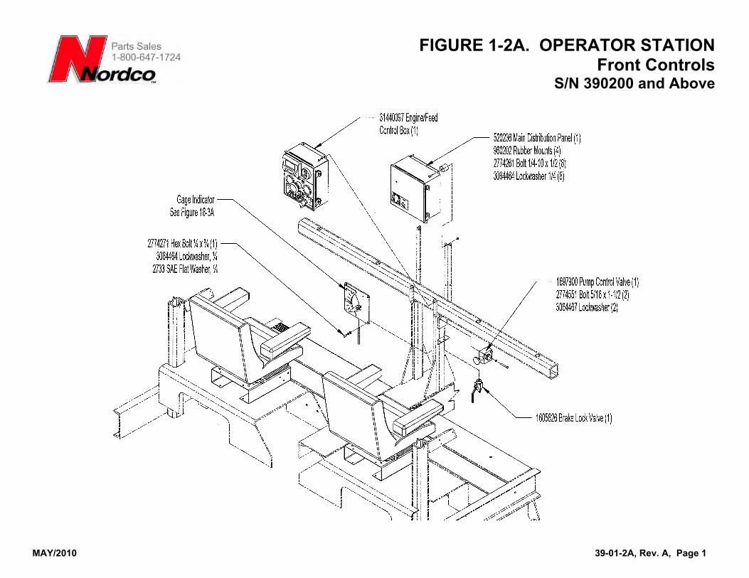
FIGURE 1-2A. OPERATOR STATION
MAY/2010 39-01-2A, Rev. A, Page 1
Front ControlsS/N 390200 and Above
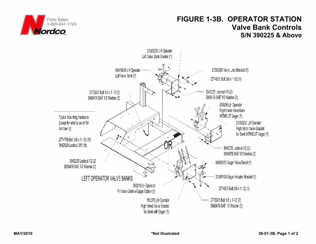
FIGURE 1-3B. OPERATOR STATION Valve Bank Controls
S/N 390225 & Above
MAY/2010 *Not Illustrated 39-01-3B, Page 1 of 2
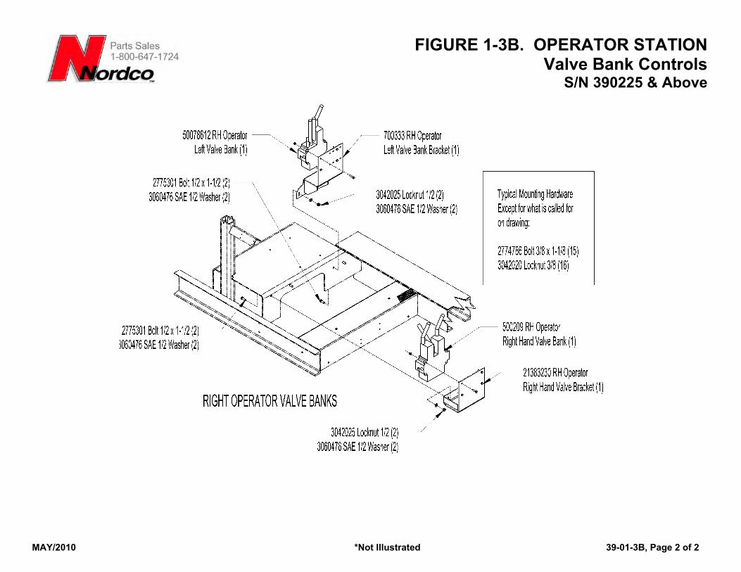
FIGURE 1-3B. OPERATOR STATION Valve Bank Controls
S/N 390225 & Above
MAY/2010 *Not Illustrated 39-01-3B, Page 2 of 2
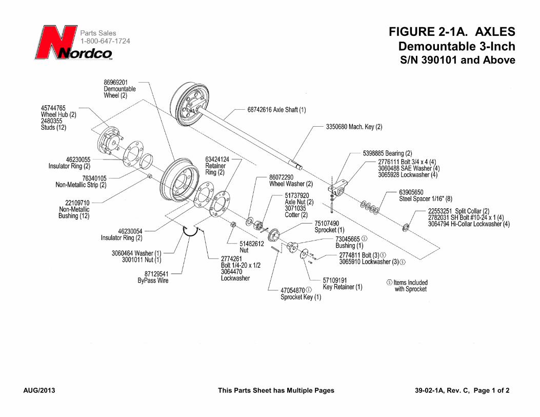
FIGURE 2-1A. AXLES Demountable 3-Inch S/N 390101 and Above
AUG/2013 This Parts Sheet has Multiple Pages 39-02-1A, Rev. C, Page 1 of 2
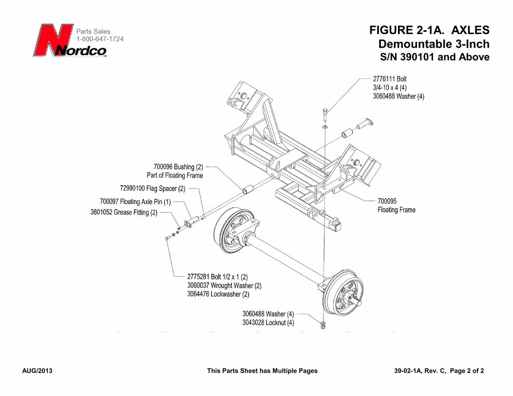
FIGURE 2-1A. AXLES Demountable 3-Inch S/N 390101 and Above
AUG/2013 This Parts Sheet has Multiple Pages 39-02-1A, Rev. C, Page 2 of 2
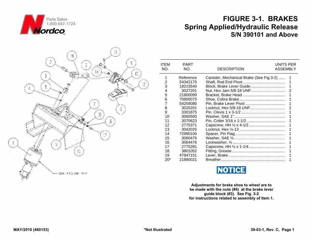
FIGURE 3-1. BRAKES Spring Applied/Hydraulic Release
S/N 390101 and Above
ITEM PART UNITS PER NO. NO. DESCRIPTION ASSEMBLY
1 Reference Canister, Mechanical Brake (See Fig 3-2) ...... 1 2 54342175 Shaft, Rod End Pivot ....................................... 1 3 18223540 Block, Brake Lever Guide................................ 1 4 3027201 Nut, Hex Jam 5/8-18 UNF............................... 2 5 21800099 Bracket, Brake Head ....................................... 1 6 70900075 Shoe, Cobra Brake.......................................... 1 7 54259080 Pin, Brake Lever Pivot..................................... 1 8 3025201 Locknut, Hex 5/8-18 UNF................................ 2 9 3301875 Pin. Clevis 1 x 3-1/2 ........................................ 1 10 3060500 Washer, SAE 1”............................................... 1 11 3070623 Pin, Cotter 3/16 x 1-1/2 ................................... 1 12 2775371 Capscrew, HH ½ x 4-1/2 ................................. 1 13 3042025 Locknut, Hex ½-13 .......................................... 1 14 72990100 Spacer, Pin Flag.............................................. 1 15 3060476 Washer, SAE ½............................................... 1 16 3064476 Lockwasher, ½ ................................................ 1 17 2775281 Capscrew, HH ½ x 1-1/4 ................................. 1 18 3801052 Fitting, Grease................................................. 1 19 47847151 Lever, Brake .................................................... 1 20* 21880021 Breather........................................................... 1
Adjustments for brake shoe to wheel are to be made with the nuts (#4) at the brake lever
guide block (#3). See Fig. 3-2 for instructions related to assembly of Item 1.
MAY/2010 (460153) *Not Illustrated 39-03-1, Rev. C, Page 1
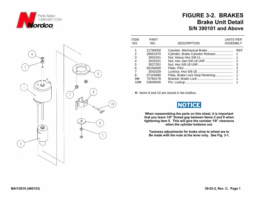
FIGURE 3-2. BRAKES Brake Unit Detail
S/N 390101 and Above
MAY/2010 (460153) 39-03-2, Rev. C, Page 1
ITEM PART UNITS PER NO. NO. DESCRIPTION ASSEMBLY
1 21790050 Canister, Mechanical Brake ............................ REF 2 28551970 Cylinder, Brake Canister Release ................... 1 3 3001041 Nut, Heavy Hex 5/8-11 .................................... 1 4 3025201 Nut, Hex Jam 5/8-18 UNF............................... 2 5 3027201 Nut, Hex 5/8-18 UNF....................................... 3 6 56156000 Plate, Pilot ....................................................... 2 7 3042029 Locknut, Hex 5/8-18 ........................................ 2 8 57104680 Plate, Brake Lock Stop Retaining.................... 1 9 75760178 Bracket, Brake Lock ........................................ 1 10 53645045 Pin, Lockup...................................................... 1
Items 9 and 10 are stored in the toolbox.
When reassembling the parts on this sheet, it is important that you leave 1/8” thread gap between Items 2 and 8 when tightening item 5. This will give the canister 1/8” clearance
when the cylinder bottoms out.
Tautness adjustments for brake shoe to wheel are to Be made with the nuts at the lever only. See Fig. 3-1.
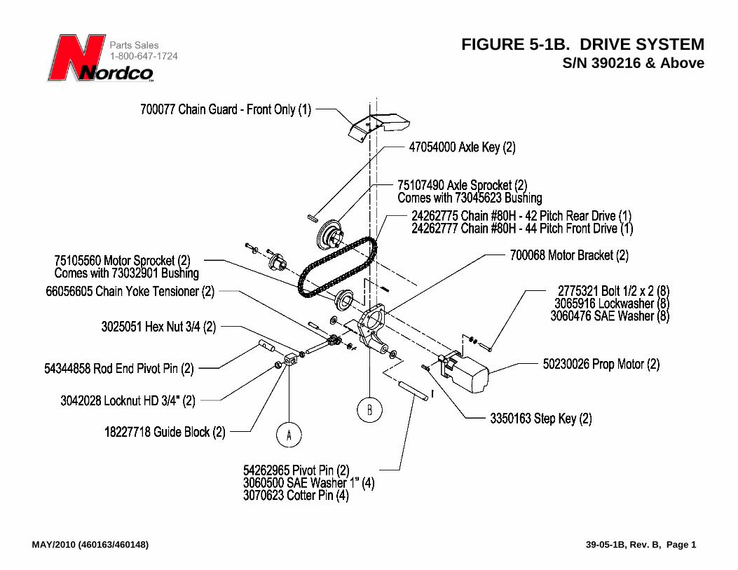
FIGURE 5-1B. DRIVE SYSTEM S/N 390216 & Above
MAY/2010 (460163/460148) 39-05-1B, Rev. B, Page 1
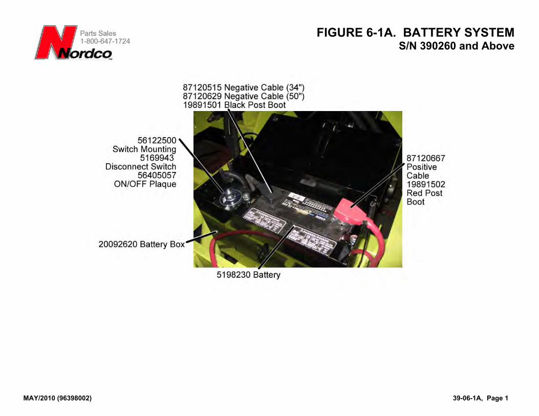
FIGURE 6-1A. BATTERY SYSTEM S/N 390260 and Above
MAY/2010 (96398002) 39-06-1A, Page 1
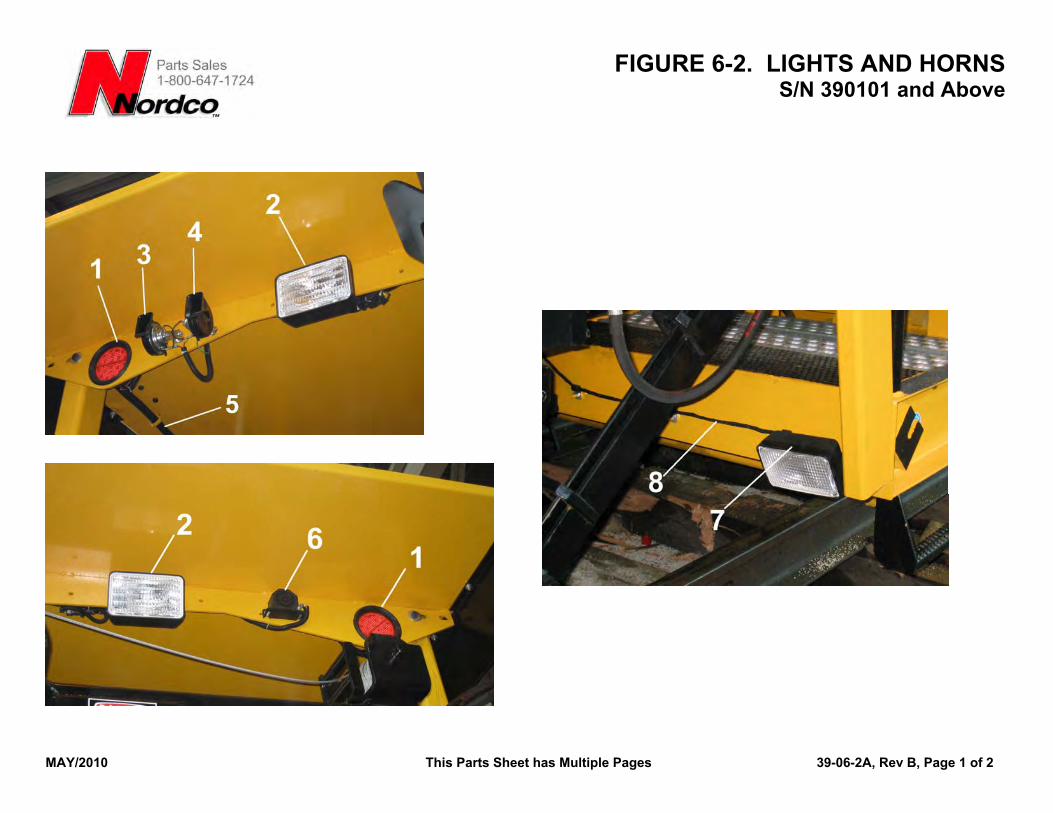
FIGURE 6-2. LIGHTS AND HORNS S/N 390101 and Above
MAY/2010 This Parts Sheet has Multiple Pages 39-06-2A, Rev B, Page 1 of 2
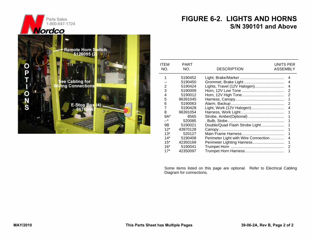
FIGURE 6-2. LIGHTS AND HORNS S/N 390101 and Above
MAY/2010 This Parts Sheet has Multiple Pages 39-06-2A, Rev B, Page 2 of 2
ITEM PART UNITS PER NO. NO. DESCRIPTION ASSEMBLY
1 5190452 Light, Brake/Marker ......................................... 4 -- 5190450 Grommet, Brake Light ..................................... 4 2 5190424 Lights, Travel (12V Halogen)........................... 4 3 5190009 Horn, 12V Low Tone ....................................... 2 4 5190012 Horn, 12V High Tone....................................... 2 5 96391045 Harness, Canopy............................................. 1 6 5190063 Alarm, Backup................................................. 2 7 5190428 Light, Work (12V Halogen) .............................. 4 8 96391054 Harness, Work Light........................................ 1 9A* 8565 Strobe, Amber(Optional) ................................. 1 --* 520085 . Bulb, Stobe.................................................... 1 9B 5190021 Double/Quad Flash Strobe Light ..................... 1 12* 43970128 Canopy ............................................................ 1 13* 520127 Main Frame Harness....................................... 1 14* 5190408 Perimeter Light with Wire Connection............. 4 15* 42350169 Perimeter Lighting Harness............................. 1 16* 5190041 Trumpet Horn ................................................. 2 17* 42350097 Trumpet Horn Harness.................................... 1 Some items listed on this page are optional. Refer to Electrical Cabling Diagram for connections.
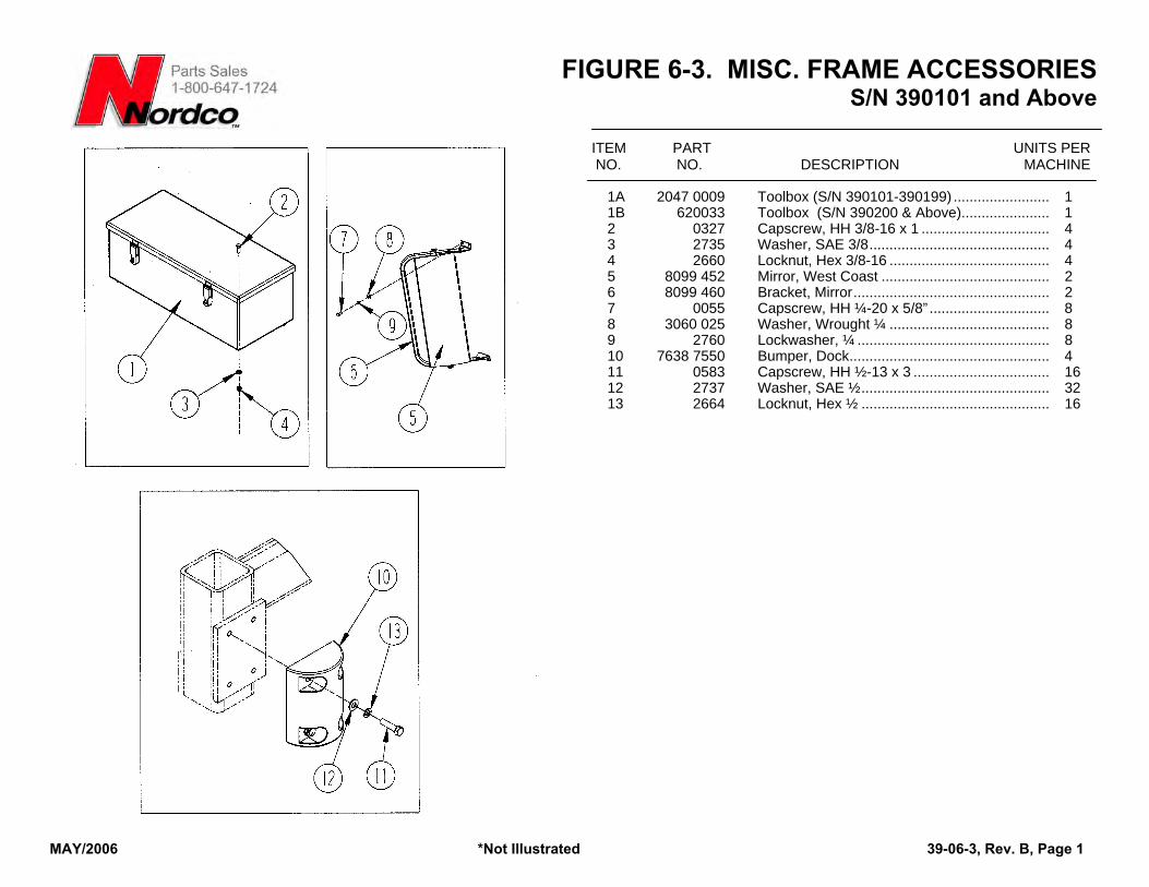
FIGURE 6-3. MISC. FRAME ACCESSORIES S/N 390101 and Above
MAY/2006 *Not Illustrated 39-06-3, Rev. B, Page 1
ITEM PART UNITS PER NO. NO. DESCRIPTION MACHINE
1A 2047 0009 Toolbox (S/N 390101-390199) ........................ 1 1B 620033 Toolbox (S/N 390200 & Above)...................... 1 2 0327 Capscrew, HH 3/8-16 x 1 ................................ 4 3 2735 Washer, SAE 3/8............................................. 4 4 2660 Locknut, Hex 3/8-16 ........................................ 4 5 8099 452 Mirror, West Coast .......................................... 2 6 8099 460 Bracket, Mirror................................................. 2 7 0055 Capscrew, HH ¼-20 x 5/8” .............................. 8 8 3060 025 Washer, Wrought ¼ ........................................ 8 9 2760 Lockwasher, ¼ ................................................ 8 10 7638 7550 Bumper, Dock.................................................. 4 11 0583 Capscrew, HH ½-13 x 3 .................................. 16 12 2737 Washer, SAE ½............................................... 32 13 2664 Locknut, Hex ½ ............................................... 16
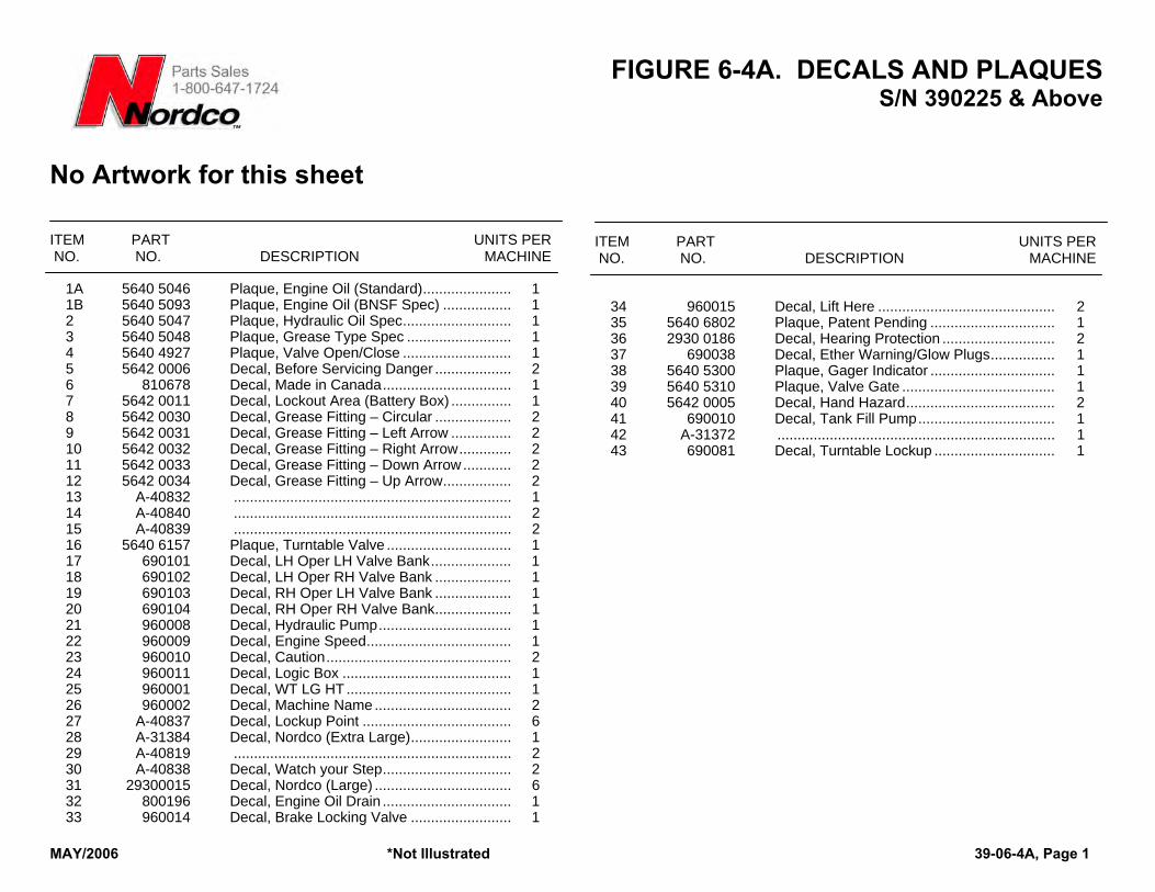
FIGURE 6-4A. DECALS AND PLAQUES S/N 390225 & Above
MAY/2006 *Not Illustrated 39-06-4A, Page 1
No Artwork for this sheet ITEM PART UNITS PER NO. NO. DESCRIPTION MACHINE
1A 5640 5046 Plaque, Engine Oil (Standard)...................... 1 1B 5640 5093 Plaque, Engine Oil (BNSF Spec) ................. 1 2 5640 5047 Plaque, Hydraulic Oil Spec........................... 1 3 5640 5048 Plaque, Grease Type Spec .......................... 1 4 5640 4927 Plaque, Valve Open/Close ........................... 1 5 5642 0006 Decal, Before Servicing Danger ................... 2 6 810678 Decal, Made in Canada................................ 1 7 5642 0011 Decal, Lockout Area (Battery Box) ............... 1 8 5642 0030 Decal, Grease Fitting – Circular ................... 2 9 5642 0031 Decal, Grease Fitting – Left Arrow ............... 2 10 5642 0032 Decal, Grease Fitting – Right Arrow............. 2 11 5642 0033 Decal, Grease Fitting – Down Arrow ............ 2 12 5642 0034 Decal, Grease Fitting – Up Arrow................. 2 13 A-40832 ..................................................................... 1 14 A-40840 ..................................................................... 2 15 A-40839 ..................................................................... 2 16 5640 6157 Plaque, Turntable Valve ............................... 1 17 690101 Decal, LH Oper LH Valve Bank.................... 1 18 690102 Decal, LH Oper RH Valve Bank ................... 1 19 690103 Decal, RH Oper LH Valve Bank ................... 1 20 690104 Decal, RH Oper RH Valve Bank................... 1 21 960008 Decal, Hydraulic Pump................................. 1 22 960009 Decal, Engine Speed.................................... 1 23 960010 Decal, Caution.............................................. 2 24 960011 Decal, Logic Box .......................................... 1 25 960001 Decal, WT LG HT ......................................... 1 26 960002 Decal, Machine Name .................................. 2 27 A-40837 Decal, Lockup Point ..................................... 6 28 A-31384 Decal, Nordco (Extra Large)......................... 1 29 A-40819 ..................................................................... 2 30 A-40838 Decal, Watch your Step................................ 2 31 29300015 Decal, Nordco (Large) .................................. 6 32 800196 Decal, Engine Oil Drain ................................ 1 33 960014 Decal, Brake Locking Valve ......................... 1
ITEM PART UNITS PER NO. NO. DESCRIPTION MACHINE
34 960015 Decal, Lift Here ............................................ 2 35 5640 6802 Plaque, Patent Pending ............................... 1 36 2930 0186 Decal, Hearing Protection ............................ 2 37 690038 Decal, Ether Warning/Glow Plugs................ 1 38 5640 5300 Plaque, Gager Indicator ............................... 1 39 5640 5310 Plaque, Valve Gate ...................................... 1 40 5642 0005 Decal, Hand Hazard..................................... 2 41 690010 Decal, Tank Fill Pump.................................. 1 42 A-31372 ..................................................................... 1 43 690081 Decal, Turntable Lockup .............................. 1
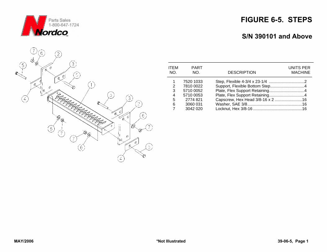
FIGURE 6-5. STEPS
S/N 390101 and Above
ITEM PART UNITS PER NO. NO. DESCRIPTION MACHINE
1 7520 1033 Step, Flexible 4-3/4 x 23-1/4 ...............................2 2 7810 0022 Support, Flexible Bottom Step..............................4 3 5710 0052 Plate, Flex Support Retaining...............................4 4 5710 0053 Plate, Flex Support Retaining...............................4 5 2774 821 Capscrew, Hex Head 3/8-16 x 2 ........................16 6 3060 031 Washer, SAE 3/8................................................16 7 3042 020 Locknut, Hex 3/8-16 ...........................................16
MAY/2006 *Not Illustrated 39-06-5, Page 1
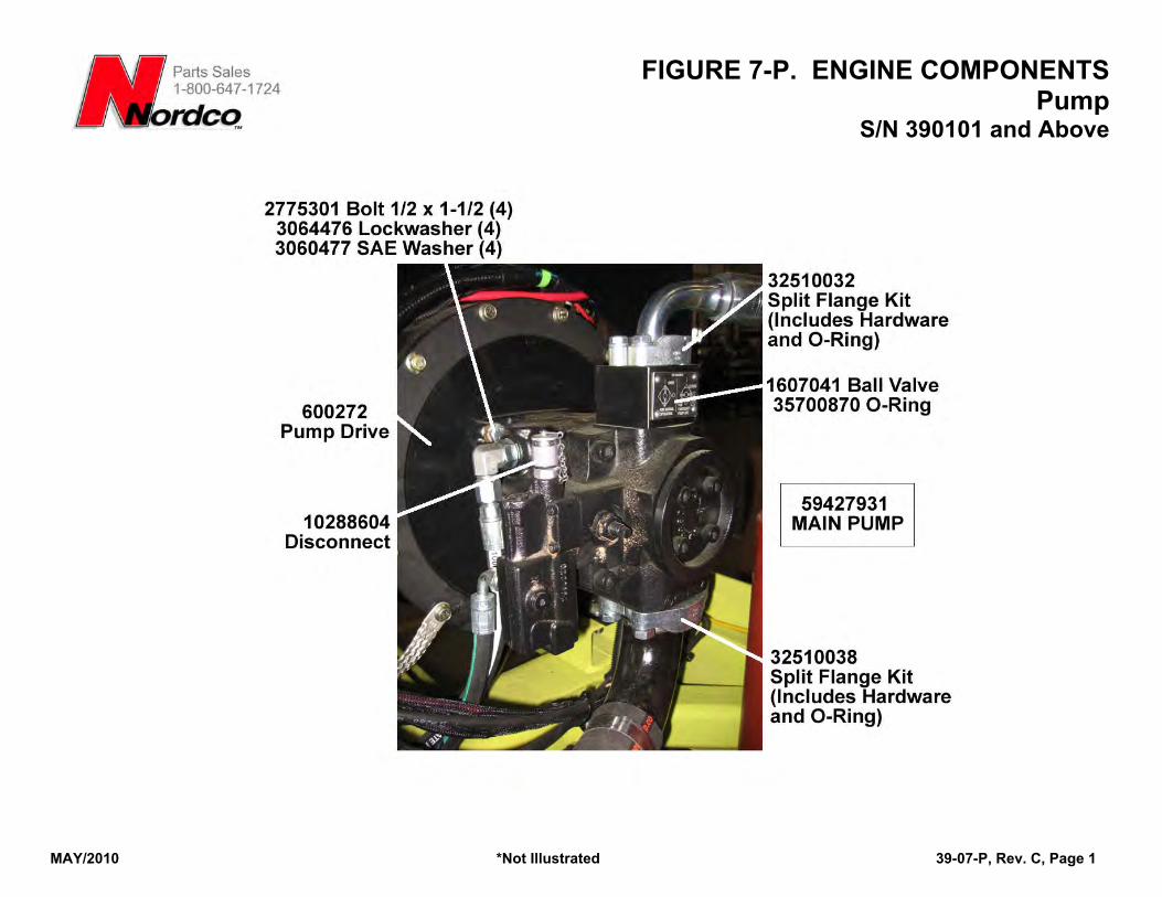
FIGURE 7-P. ENGINE COMPONENTS Pump
MAY/2010 *Not Illustrated 39-07-P, Rev. C, Page 1
S/N 390101 and Above
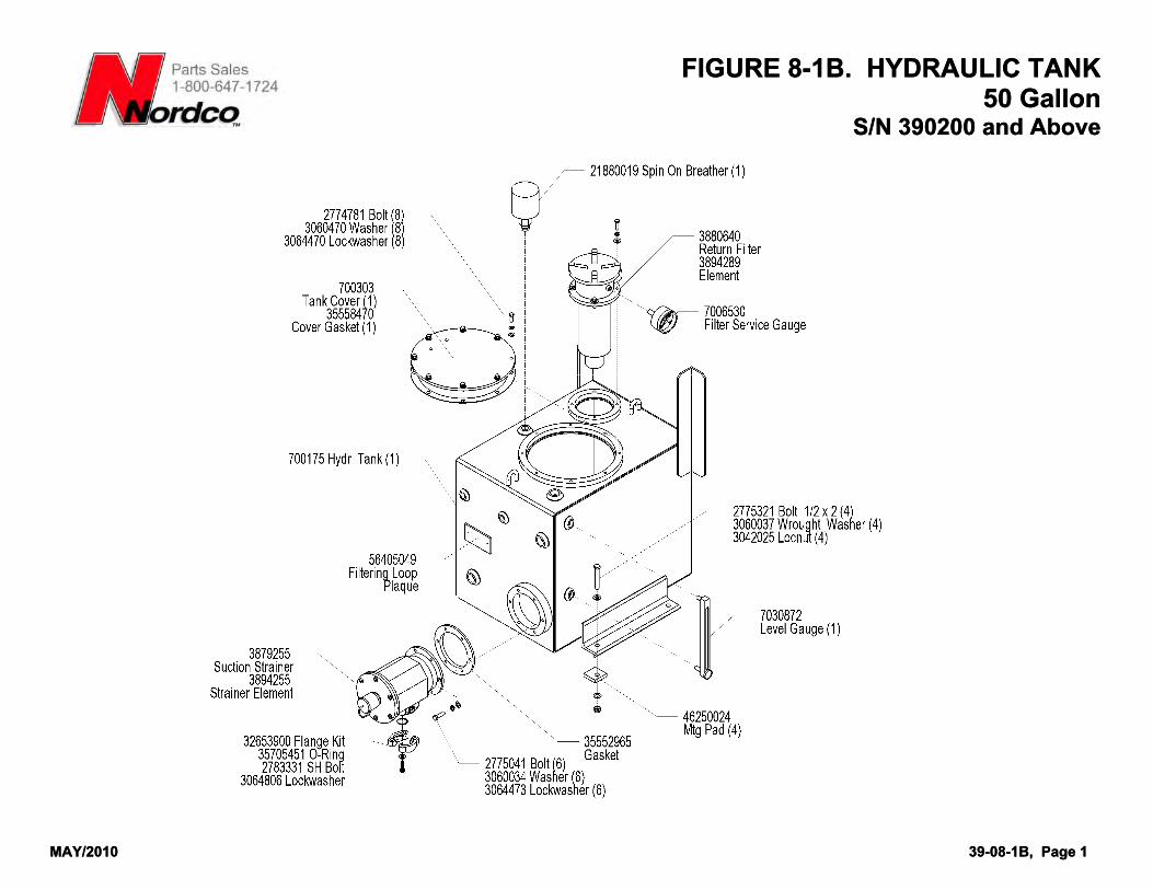
FIGURE 8-1B. HYDRAULIC TANK 50 Gallon
S/N 390200 and Above
FIGURE 8-1B. HYDRAULIC TANK 50 Gallon
S/N 390200 and Above
MAY/2010 39-08-1B, Page 1
MAY/2010 39-08-1B, Page 1
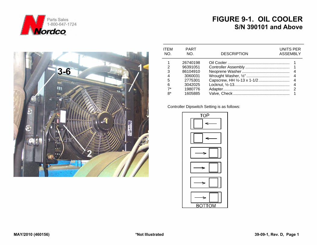
FIGURE 9-1. OIL COOLER S/N 390101 and Above
ITEM PART UNITS PER NO. NO. DESCRIPTION ASSEMBLY
1 26740198 Oil Cooler ........................................................ 1 2 96391051 Controller Assembly ........................................ 1 3 86104910 Neoprene Washer ........................................... 4 4 3060031 Wrought Washer, ½” ....................................... 4 5 2775301 Capscrew, HH ½-13 x 1-1/2 ............................ 4 6 3042025 Locknut, ½-13.................................................. 4 7* 1980776 Adapter............................................................ 2 8* 1605885 Valve, Check ................................................... 1 Controller Dipswitch Setting is as follows:
MAY/2010 (460156) *Not Illustrated 39-09-1, Rev. D, Page 1
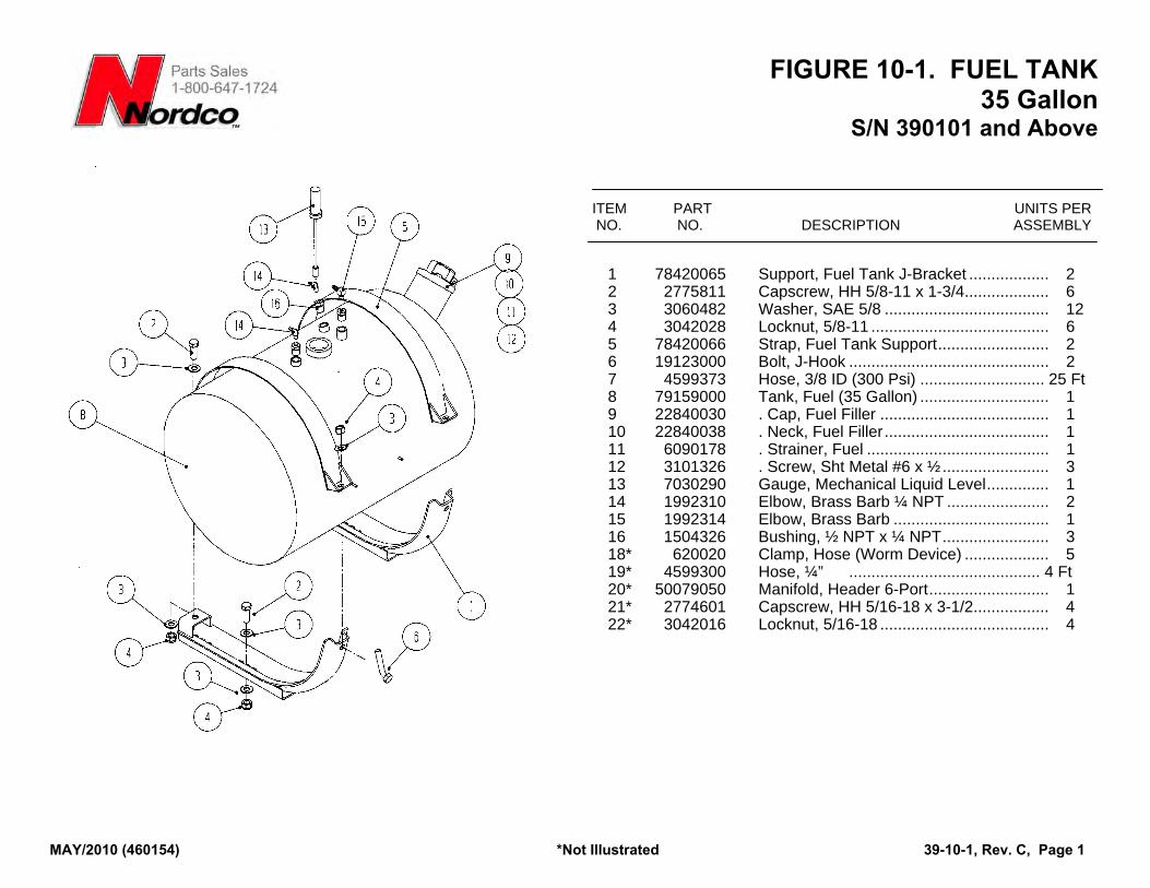
FIGURE 10-1. FUEL TANK 35 Gallon
S/N 390101 and Above
MAY/2010 (460154) *Not Illustrated 39-10-1, Rev. C, Page 1
ITEM PART UNITS PER NO. NO. DESCRIPTION ASSEMBLY
1 78420065 Support, Fuel Tank J-Bracket .................. 2 2 2775811 Capscrew, HH 5/8-11 x 1-3/4................... 6 3 3060482 Washer, SAE 5/8 ..................................... 12 4 3042028 Locknut, 5/8-11 ........................................ 6 5 78420066 Strap, Fuel Tank Support......................... 2 6 19123000 Bolt, J-Hook ............................................. 2 7 4599373 Hose, 3/8 ID (300 Psi) ............................ 25 Ft 8 79159000 Tank, Fuel (35 Gallon) ............................. 1 9 22840030 . Cap, Fuel Filler ...................................... 1 10 22840038 . Neck, Fuel Filler ..................................... 1 11 6090178 . Strainer, Fuel ......................................... 1 12 3101326 . Screw, Sht Metal #6 x ½........................ 3 13 7030290 Gauge, Mechanical Liquid Level.............. 1 14 1992310 Elbow, Brass Barb ¼ NPT ....................... 2 15 1992314 Elbow, Brass Barb ................................... 1 16 1504326 Bushing, ½ NPT x ¼ NPT........................ 3 18* 620020 Clamp, Hose (Worm Device) ................... 5 19* 4599300 Hose, ¼” ........................................... 4 Ft 20* 50079050 Manifold, Header 6-Port........................... 1 21* 2774601 Capscrew, HH 5/16-18 x 3-1/2................. 4 22* 3042016 Locknut, 5/16-18 ...................................... 4
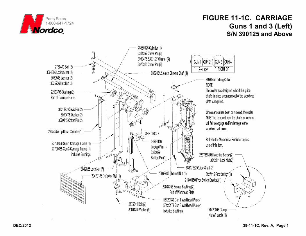
FIGURE 11-1C. CARRIAGE Guns 1 and 3 (Left)
S/N 390125 and Above
DEC/2012 39-11-1C, Rev. A, Page 1
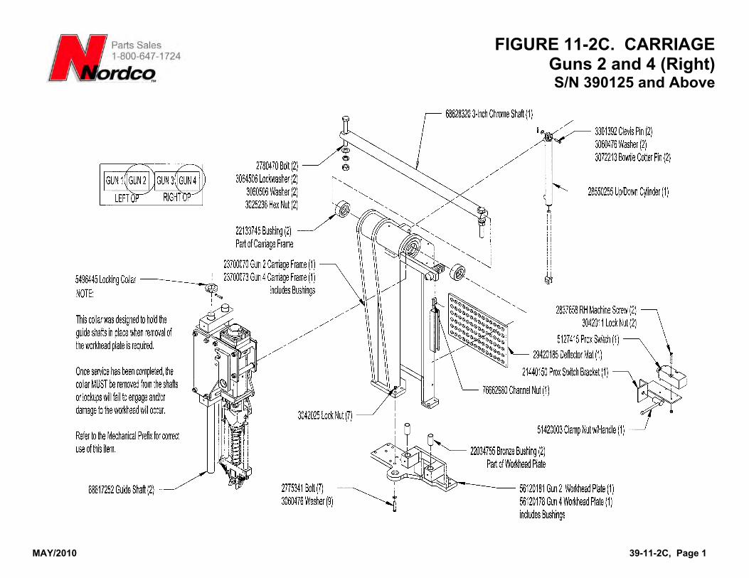
FIGURE 11-2C. CARRIAGE Guns 2 and 4 (Right) S/N 390125 and Above
MAY/2010 39-11-2C, Page 1
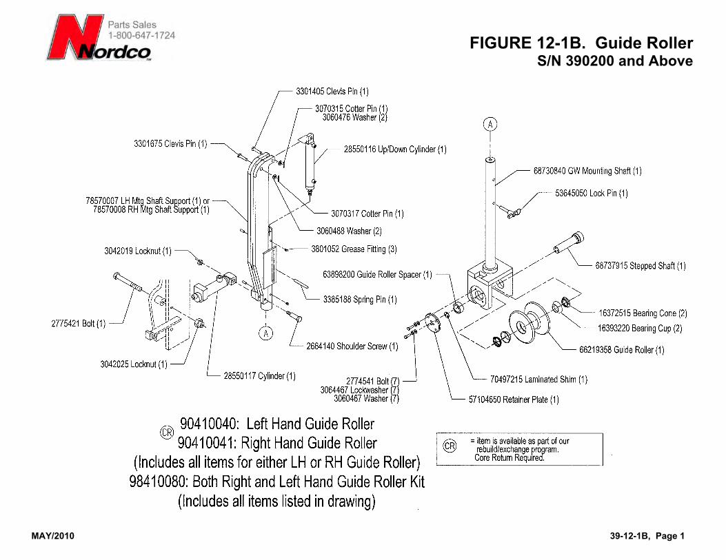
FIGURE 12-1B. Guide Roller
MAY/2010 39-12-1B, Page 1
S/N 390200 and Above
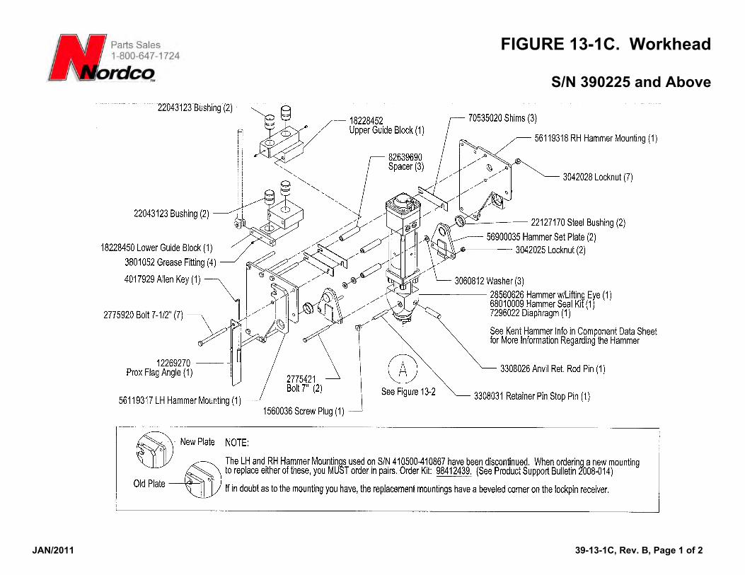
FIGURE 13-1C. Workhead
S/N 390225 and Above
JAN/2011 39-13-1C, Rev. B, Page 1 of 2
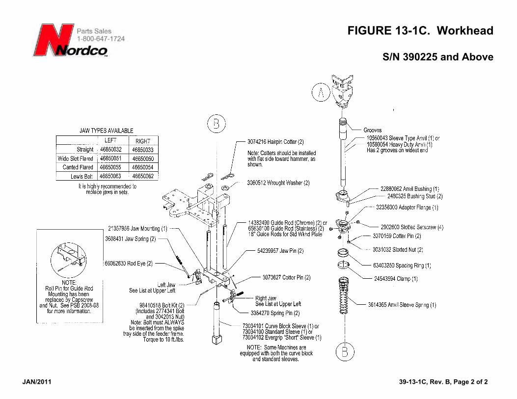
FIGURE 13-1C. Workhead
S/N 390225 and Above
JAN/2011 39-13-1C, Rev. B, Page 2 of 2
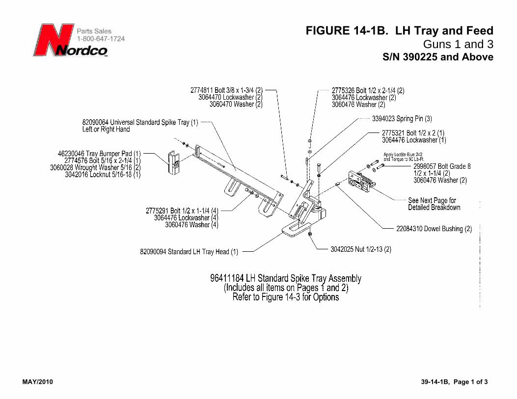
FIGURE 14-1B. LH Tray and Feed
MAY/2010 39-14-1B, Page 1 of 3
Guns 1 and 3 S/N 390225 and Above
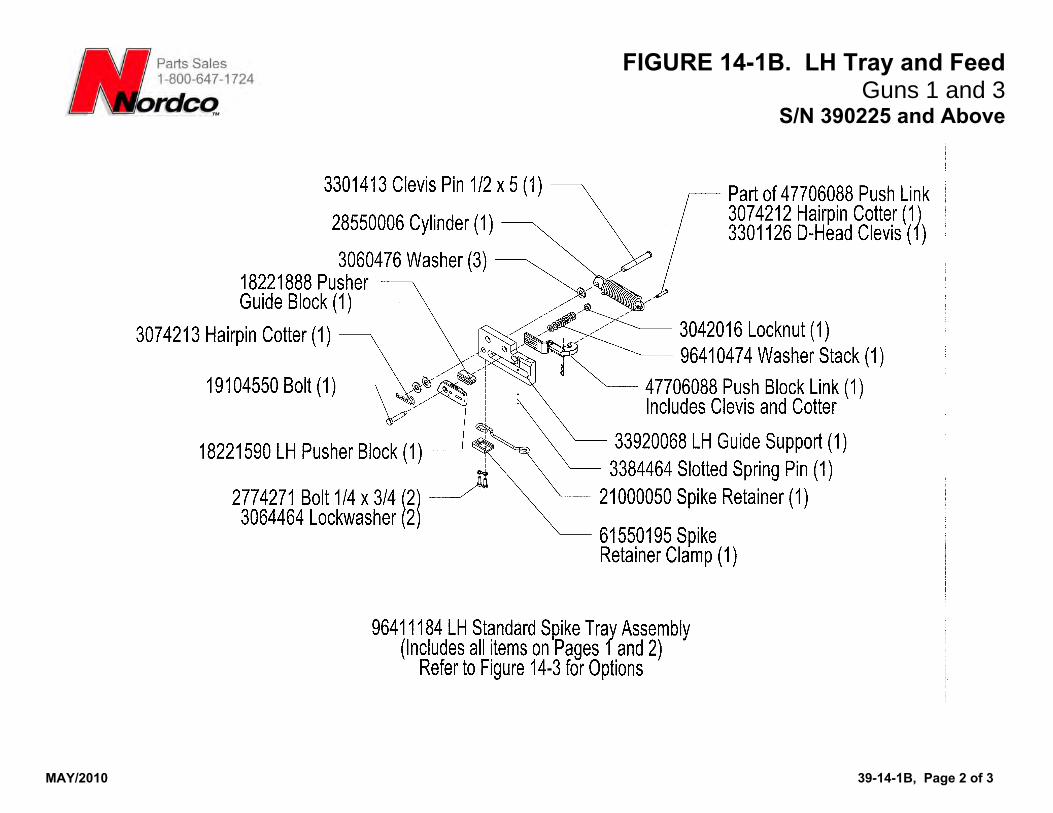
FIGURE 14-1B. LH Tray and Feed
MAY/2010 39-14-1B, Page 2 of 3
Guns 1 and 3 S/N 390225 and Above
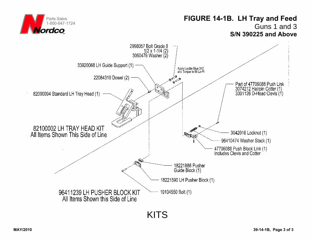
FIGURE 14-1B. LH Tray and Feed
MAY/2010 39-14-1B, Page 3 of 3
Guns 1 and 3 S/N 390225 and Above
KITS
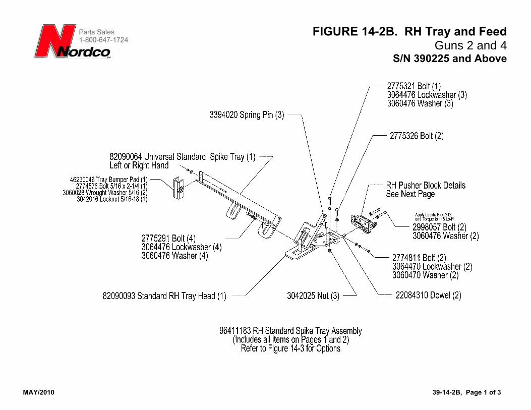
FIGURE 14-2B. RH Tray and Feed
MAY/2010 39-14-2B, Page 1 of 3
Guns 2 and 4 S/N 390225 and Above
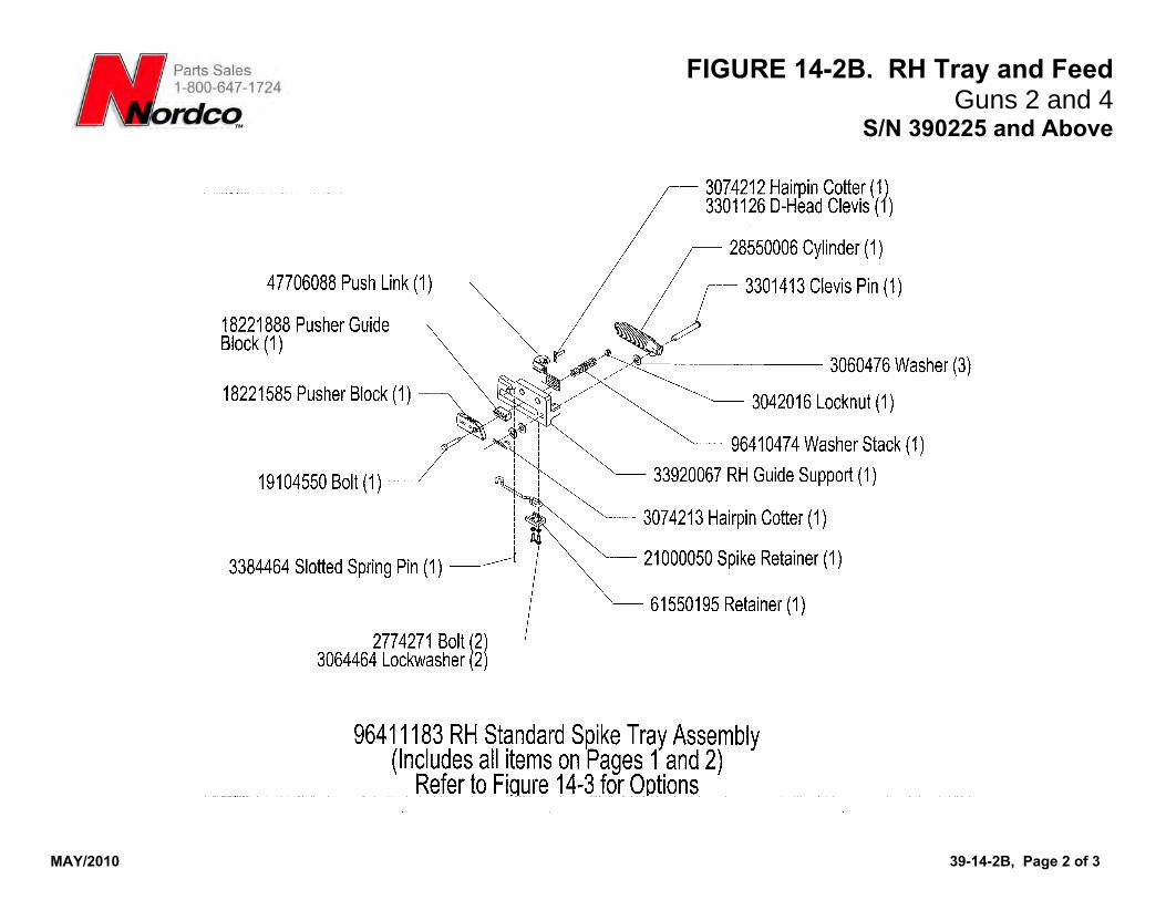
FIGURE 14-2B. RH Tray and Feed
MAY/2010 39-14-2B, Page 2 of 3
Guns 2 and 4 S/N 390225 and Above
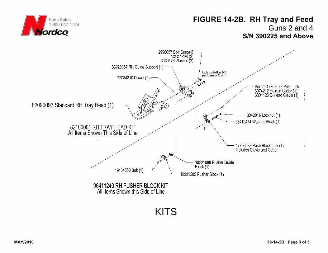
FIGURE 14-2B. RH Tray and Feed
MAY/2010 39-14-2B, Page 3 of 3
Guns 2 and 4 S/N 390225 and Above
KITS
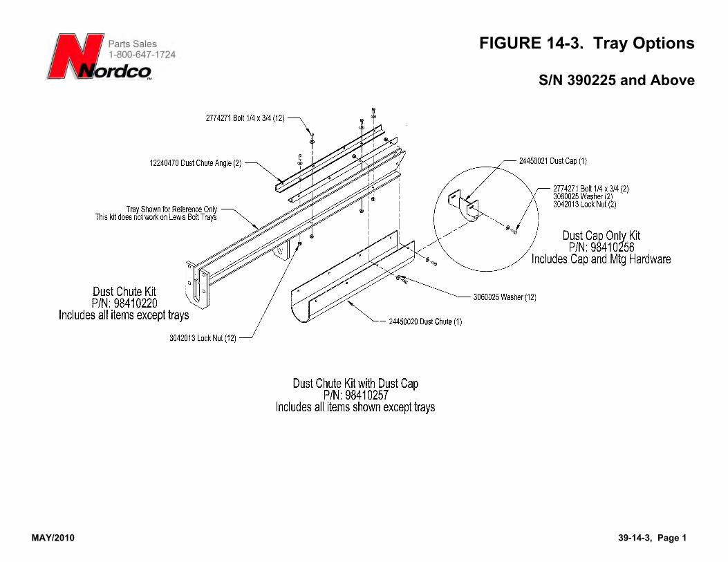
FIGURE 14-3. Tray Options
MAY/2010 39-14-3, Page 1
S/N 390225 and Above
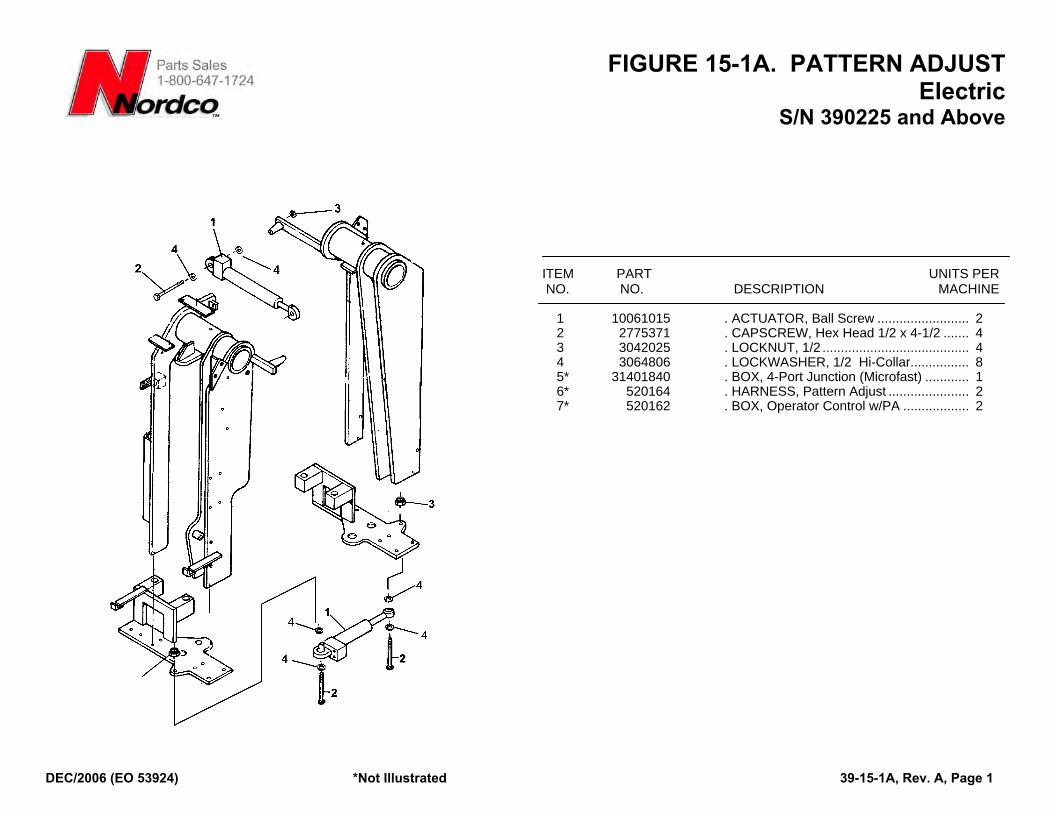
FIGURE 15-1A. PATTERN ADJUST Electric
S/N 390225 and Above
ITEM PART UNITS PER NO. NO. DESCRIPTION MACHINE
1 10061015 . ACTUATOR, Ball Screw ......................... 2 2 2775371 . CAPSCREW, Hex Head 1/2 x 4-1/2 ....... 4 3 3042025 . LOCKNUT, 1/2 ........................................ 4 4 3064806 . LOCKWASHER, 1/2 Hi-Collar................ 8 5* 31401840 . BOX, 4-Port Junction (Microfast) ............ 1 6* 520164 . HARNESS, Pattern Adjust ...................... 2 7* 520162 . BOX, Operator Control w/PA .................. 2
DEC/2006 (EO 53924) *Not Illustrated 39-15-1A, Rev. A, Page 1
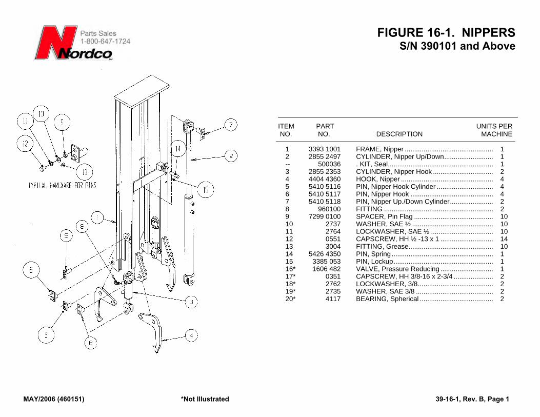
FIGURE 16-1. NIPPERS S/N 390101 and Above
ITEM PART UNITS PER NO. NO. DESCRIPTION MACHINE
1 3393 1001 FRAME, Nipper ............................................... 1 2 2855 2497 CYLINDER, Nipper Up/Down.......................... 1 -- 500036 . KIT, Seal........................................................ 1 3 2855 2353 CYLINDER, Nipper Hook ................................ 2 4 4404 4360 HOOK, Nipper ................................................. 4 5 5410 5116 PIN, Nipper Hook Cylinder .............................. 4 6 5410 5117 PIN, Nipper Hook ............................................ 4 7 5410 5118 PIN, Nipper Up./Down Cylinder....................... 2 8 960100 FITTING .......................................................... 2 9 7299 0100 SPACER, Pin Flag .......................................... 10 10 2737 WASHER, SAE ½ ........................................... 10 11 2764 LOCKWASHER, SAE ½ ................................. 10 12 0551 CAPSCREW, HH ½ -13 x 1 ............................ 14 13 3004 FITTING, Grease............................................. 10 14 5426 4350 PIN, Spring ...................................................... 1 15 3385 053 PIN, Lockup..................................................... 1 16* 1606 482 VALVE, Pressure Reducing ............................ 1 17* 0351 CAPSCREW, HH 3/8-16 x 2-3/4 ..................... 2 18* 2762 LOCKWASHER, 3/8........................................ 2 19* 2735 WASHER, SAE 3/8 ......................................... 2 20* 4117 BEARING, Spherical ....................................... 2
MAY/2006 (460151) *Not Illustrated 39-16-1, Rev. B, Page 1
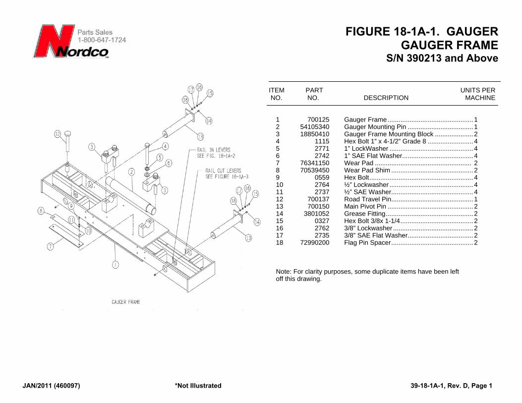
FIGURE 18-1A-1. GAUGER GAUGER FRAME
S/N 390213 and Above
JAN/2011 (460097) *Not Illustrated 39-18-1A-1, Rev. D, Page 1
ITEM PART UNITS PER NO. NO. DESCRIPTION MACHINE
1 700125 Gauger Frame............................................... 1 2 54105340 Gauger Mounting Pin .................................... 1 3 18850410 Gauger Frame Mounting Block ..................... 2 4 1115 Hex Bolt 1” x 4-1/2” Grade 8 ......................... 4 5 2771 1” LockWasher .............................................. 4 6 2742 1” SAE Flat Washer....................................... 4 7 76341150 Wear Pad ..................................................... 2 8 70539450 Wear Pad Shim ............................................. 2 9 0559 Hex Bolt......................................................... 4 10 2764 ½” Lockwasher .............................................. 4 11 2737 ½” SAE Washer............................................. 4 12 700137 Road Travel Pin............................................. 1 13 700150 Main Pivot Pin ............................................... 2 14 3801052 Grease Fitting................................................ 2 15 0327 Hex Bolt 3/8x 1-1/4........................................ 2 16 2762 3/8” Lockwasher ............................................ 2 17 2735 3/8” SAE Flat Washer.................................... 2 18 72990200 Flag Pin Spacer............................................. 2 Note: For clarity purposes, some duplicate items have been left off this drawing.
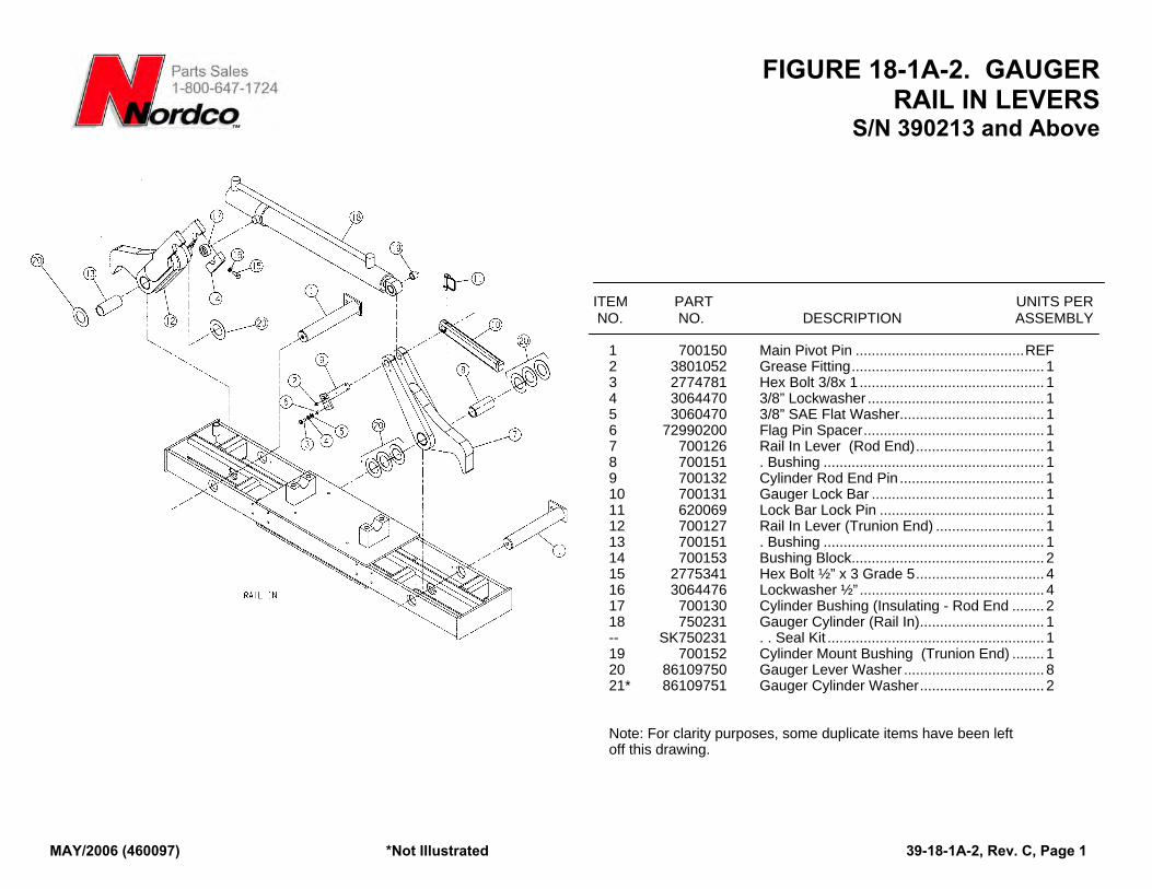
FIGURE 18-1A-2. GAUGER RAIL IN LEVERS
S/N 390213 and Above
ITEM PART UNITS PER NO. NO. DESCRIPTION ASSEMBLY
1 700150 Main Pivot Pin ..........................................REF 2 3801052 Grease Fitting................................................ 1 3 2774781 Hex Bolt 3/8x 1 .............................................. 1 4 3064470 3/8” Lockwasher ............................................ 1 5 3060470 3/8” SAE Flat Washer.................................... 1 6 72990200 Flag Pin Spacer............................................. 1 7 700126 Rail In Lever (Rod End)................................ 1 8 700151 . Bushing ....................................................... 1 9 700132 Cylinder Rod End Pin .................................... 1 10 700131 Gauger Lock Bar ........................................... 1 11 620069 Lock Bar Lock Pin ......................................... 1 12 700127 Rail In Lever (Trunion End) ........................... 1 13 700151 . Bushing ....................................................... 1 14 700153 Bushing Block................................................ 2 15 2775341 Hex Bolt ½” x 3 Grade 5................................ 4 16 3064476 Lockwasher ½” .............................................. 4 17 700130 Cylinder Bushing (Insulating - Rod End ........ 2 18 750231 Gauger Cylinder (Rail In)............................... 1 -- SK750231 . . Seal Kit ...................................................... 1 19 700152 Cylinder Mount Bushing (Trunion End) ........ 1 20 86109750 Gauger Lever Washer ................................... 8 21* 86109751 Gauger Cylinder Washer............................... 2 Note: For clarity purposes, some duplicate items have been left off this drawing.
MAY/2006 (460097) *Not Illustrated 39-18-1A-2, Rev. C, Page 1
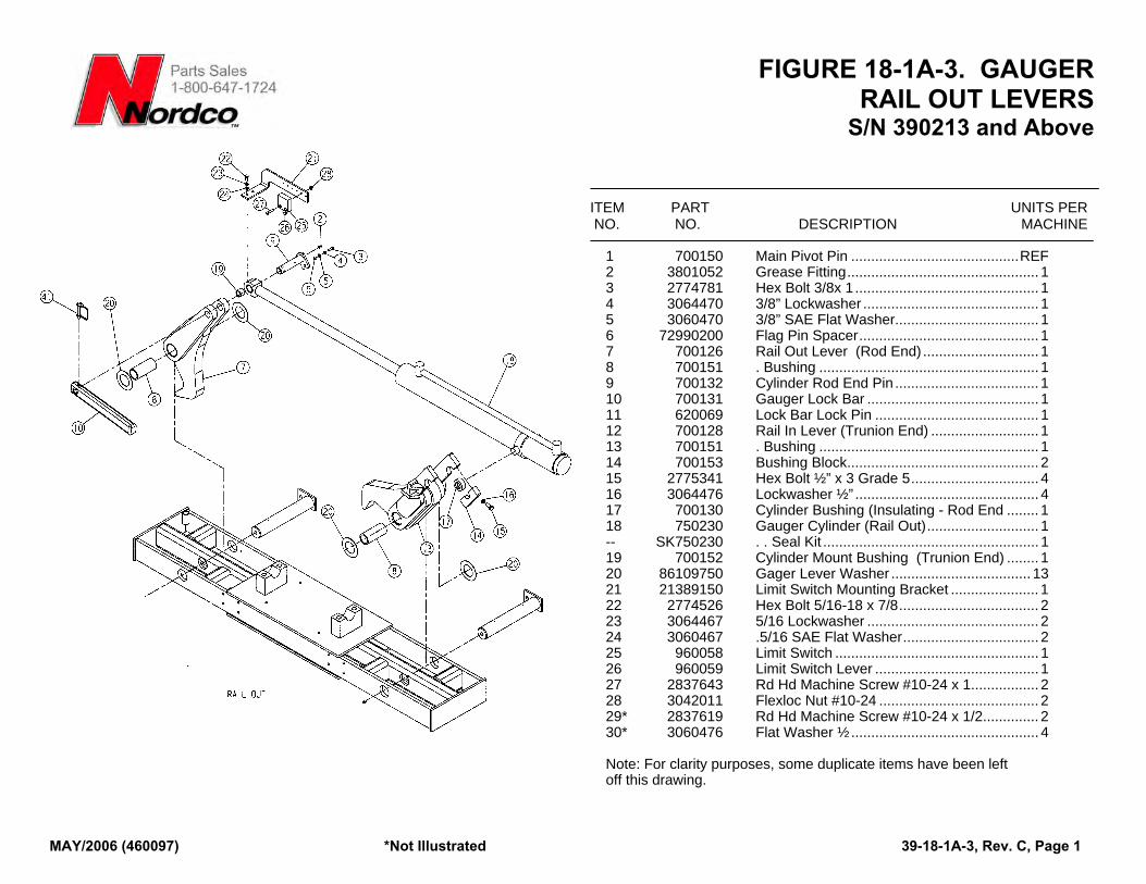
FIGURE 18-1A-3. GAUGER RAIL OUT LEVERS
S/N 390213 and Above
MAY/2006 (460097) *Not Illustrated 39-18-1A-3, Rev. C, Page 1
ITEM PART UNITS PER NO. NO. DESCRIPTION MACHINE
1 700150 Main Pivot Pin ..........................................REF 2 3801052 Grease Fitting................................................ 1 3 2774781 Hex Bolt 3/8x 1 .............................................. 1 4 3064470 3/8” Lockwasher ............................................ 1 5 3060470 3/8” SAE Flat Washer.................................... 1 6 72990200 Flag Pin Spacer............................................. 1 7 700126 Rail Out Lever (Rod End) ............................. 1 8 700151 . Bushing ....................................................... 1 9 700132 Cylinder Rod End Pin .................................... 1 10 700131 Gauger Lock Bar ........................................... 1 11 620069 Lock Bar Lock Pin ......................................... 1 12 700128 Rail In Lever (Trunion End) ........................... 1 13 700151 . Bushing ....................................................... 1 14 700153 Bushing Block................................................ 2 15 2775341 Hex Bolt ½” x 3 Grade 5................................ 4 16 3064476 Lockwasher ½” .............................................. 4 17 700130 Cylinder Bushing (Insulating - Rod End ........ 1 18 750230 Gauger Cylinder (Rail Out)............................ 1 -- SK750230 . . Seal Kit ...................................................... 1 19 700152 Cylinder Mount Bushing (Trunion End) ........ 1 20 86109750 Gager Lever Washer ................................... 13 21 21389150 Limit Switch Mounting Bracket ...................... 1 22 2774526 Hex Bolt 5/16-18 x 7/8................................... 2 23 3064467 5/16 Lockwasher ........................................... 2 24 3060467 .5/16 SAE Flat Washer.................................. 2 25 960058 Limit Switch ................................................... 1 26 960059 Limit Switch Lever ......................................... 1 27 2837643 Rd Hd Machine Screw #10-24 x 1................. 2 28 3042011 Flexloc Nut #10-24 ........................................ 2 29* 2837619 Rd Hd Machine Screw #10-24 x 1/2.............. 2 30* 3060476 Flat Washer ½............................................... 4 Note: For clarity purposes, some duplicate items have been left off this drawing.
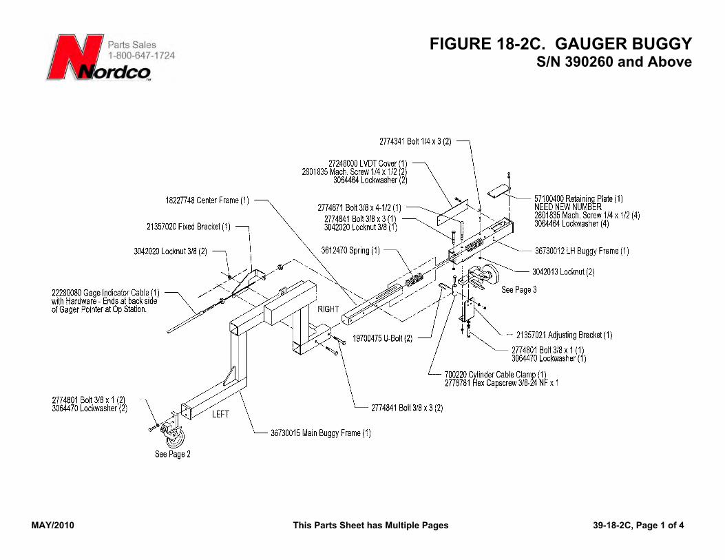
FIGURE 18-2C. GAUGER BUGGY S/N 390260 and Above
MAY/2010 This Parts Sheet has Multiple Pages 39-18-2C, Page 1 of 4
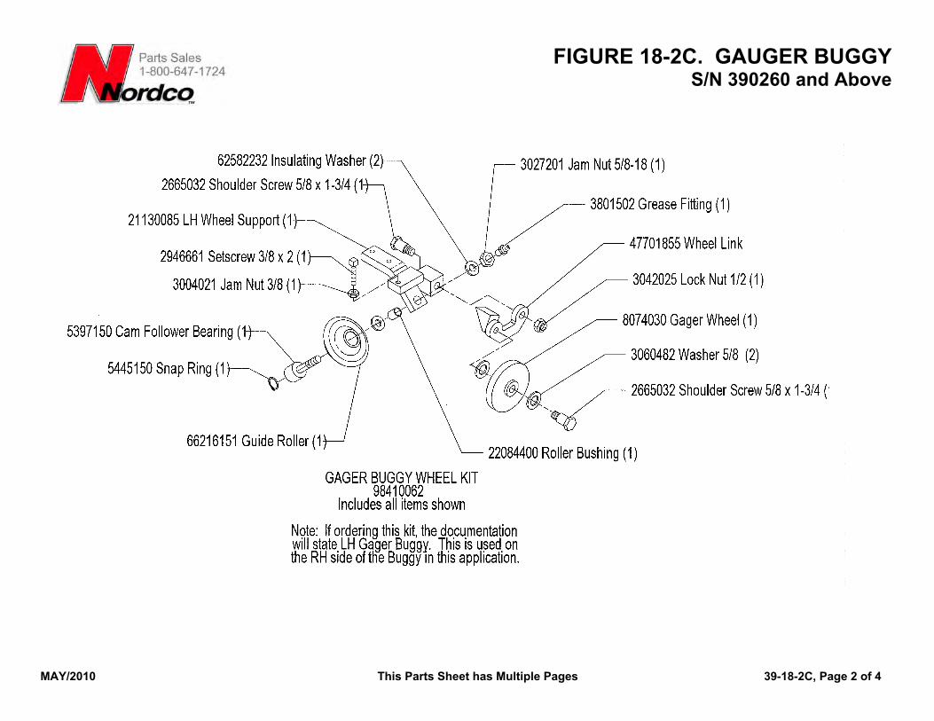
FIGURE 18-2C. GAUGER BUGGY S/N 390260 and Above
MAY/2010 This Parts Sheet has Multiple Pages 39-18-2C, Page 2 of 4
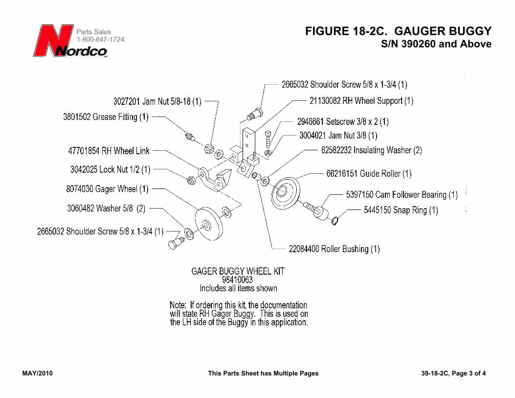
FIGURE 18-2C. GAUGER BUGGY S/N 390260 and Above
MAY/2010 This Parts Sheet has Multiple Pages 39-18-2C, Page 3 of 4
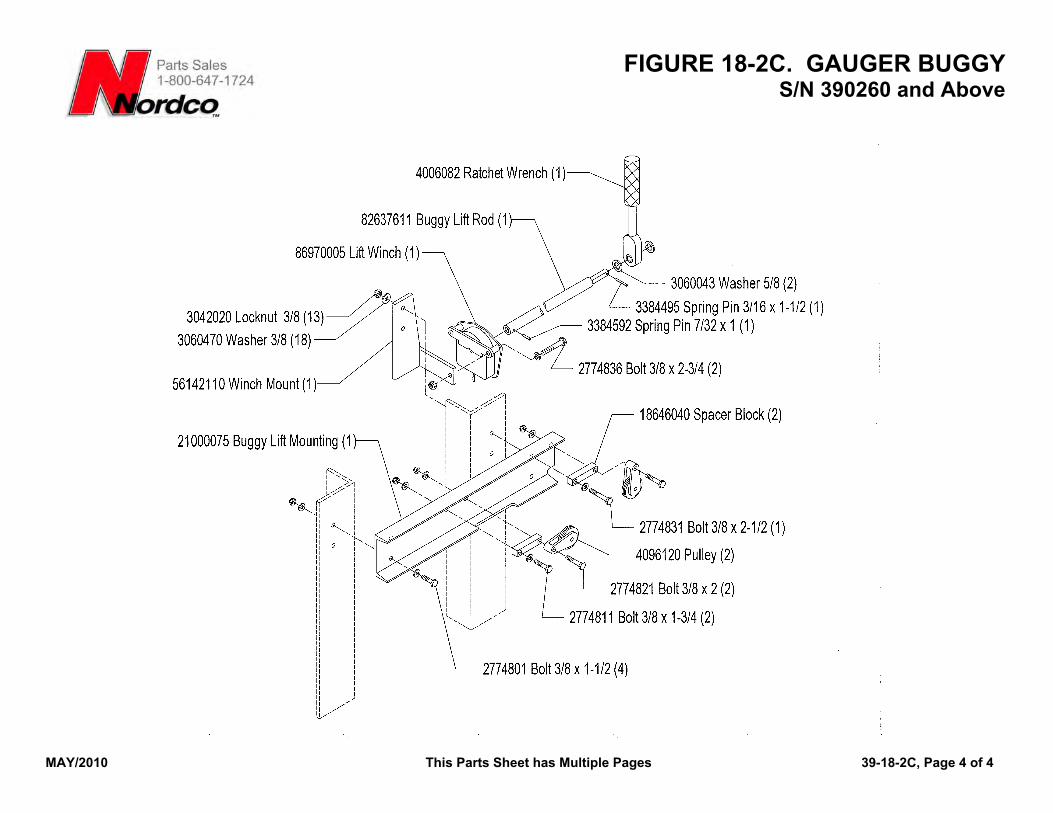
FIGURE 18-2C. GAUGER BUGGY S/N 390260 and Above
MAY/2010 This Parts Sheet has Multiple Pages 39-18-2C, Page 4 of 4
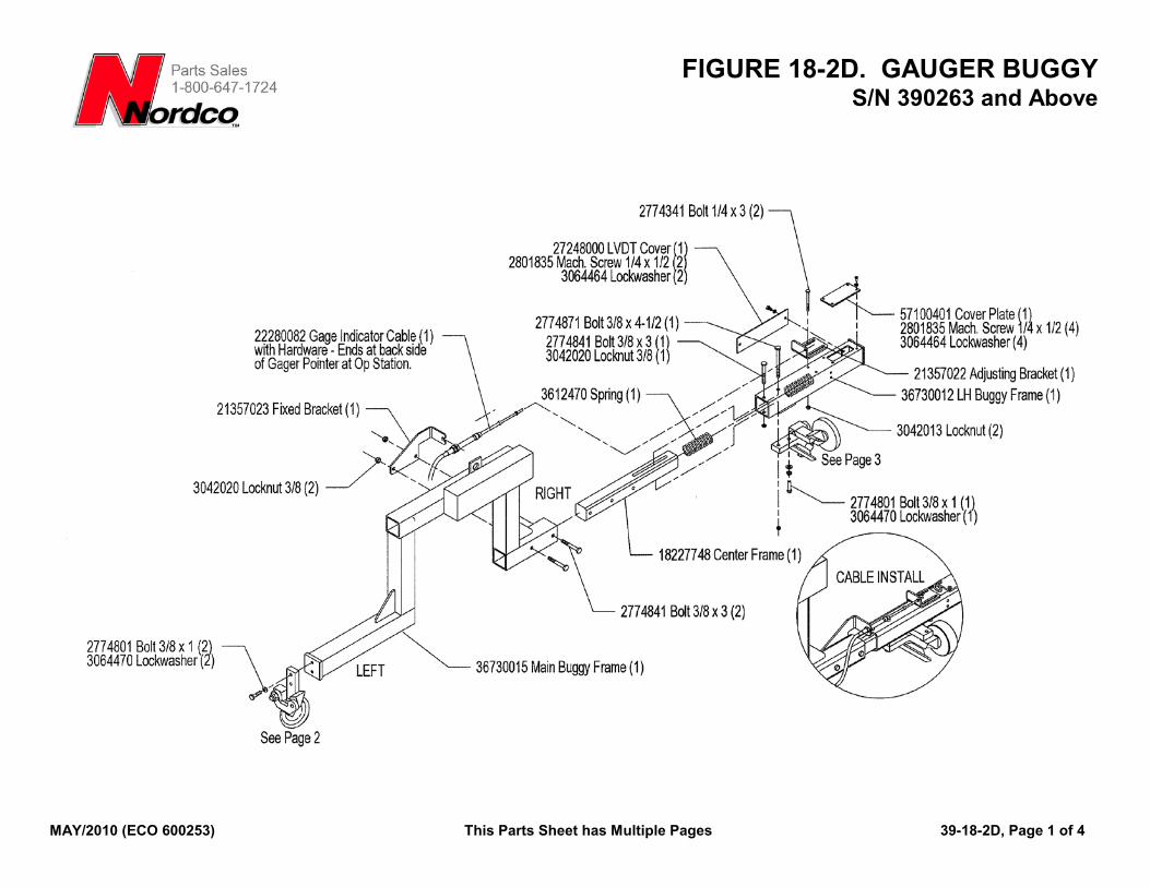
FIGURE 18-2D. GAUGER BUGGY S/N 390263 and Above
MAY/2010 (ECO 600253) This Parts Sheet has Multiple Pages 39-18-2D, Page 1 of 4
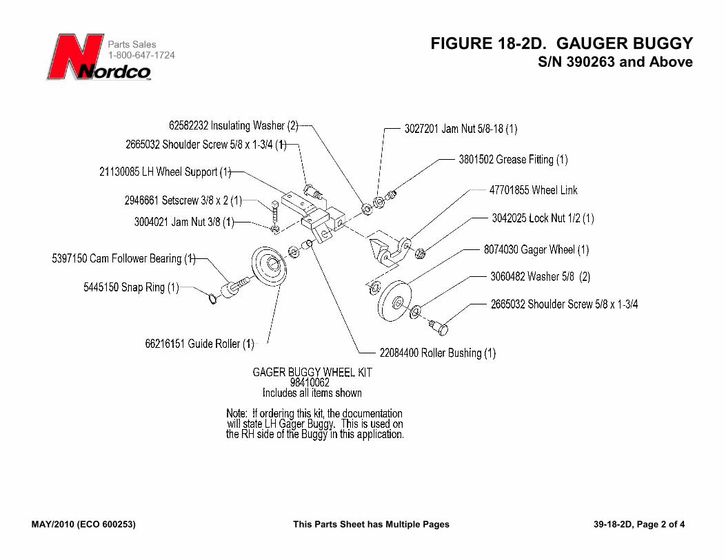
FIGURE 18-2D. GAUGER BUGGY S/N 390263 and Above
MAY/2010 (ECO 600253) This Parts Sheet has Multiple Pages 39-18-2D, Page 2 of 4
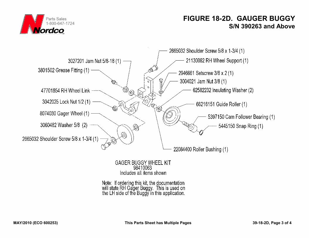
FIGURE 18-2D. GAUGER BUGGY S/N 390263 and Above
MAY/2010 (ECO 600253) This Parts Sheet has Multiple Pages 39-18-2D, Page 3 of 4
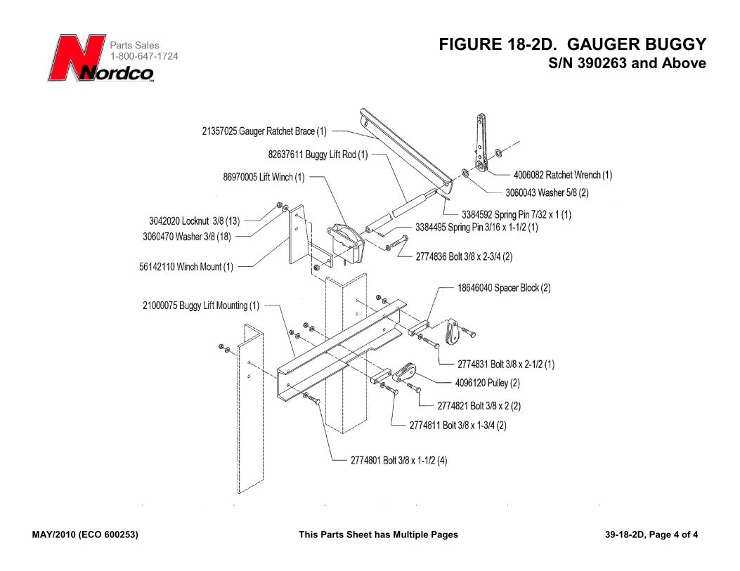
FIGURE 18-2D. GAUGER BUGGY S/N 390263 and Above
MAY/2010 (ECO 600253) This Parts Sheet has Multiple Pages 39-18-2D, Page 4 of 4
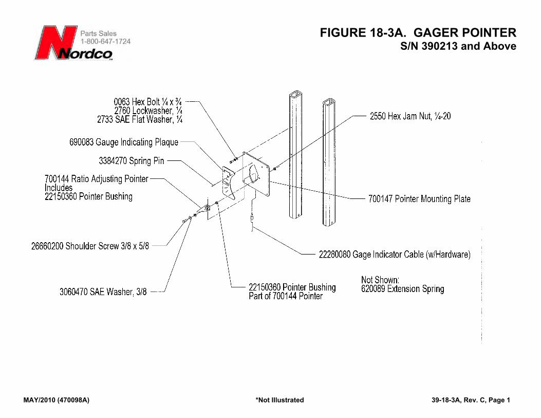
FIGURE 18-3A. GAGER POINTER S/N 390213 and Above
MAY/2010 (470098A) *Not Illustrated 39-18-3A, Rev. C, Page 1
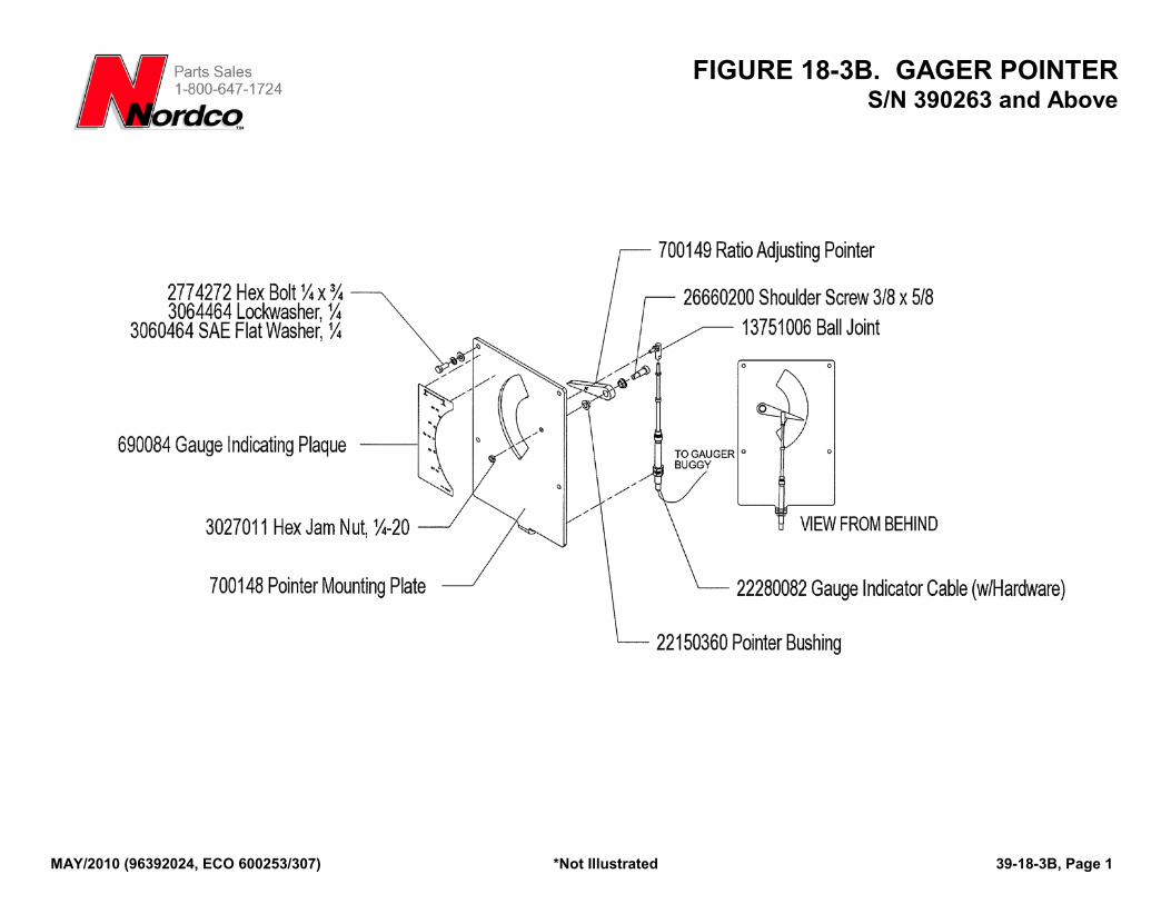
FIGURE 18-3B. GAGER POINTER S/N 390263 and Above
MAY/2010 (96392024, ECO 600253/307) *Not Illustrated 39-18-3B, Page 1
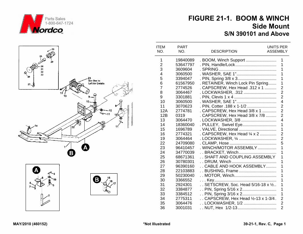
FIGURE 21-1. BOOM & WINCH Side Mount
S/N 390101 and Above
ITEM PART UNITS PER NO. NO. DESCRIPTION ASSEMBLY
1 19840089 . BOOM, Winch Support .......................... 1 2 53647797 . PIN, Handle/Lock................................... 1 3 3609604 . SPRING ................................................. 1 4 3060500 . WASHER, SAE 1”.................................. 1 5 3394047 . PIN, Spring 3/8 x 3................................. 1 6 61567950 . RETAINER, Winch Lock Pin Spring....... 1 7 2774526 . CAPSCREW, Hex Head .312 x 1 .......... 2 8 3064467 . LOCKWASHER, .312 ............................ 2 9 3301881 . PIN, Clevis 1 x 4 .................................... 2 10 3060500 . WASHER, SAE 1”.................................. 4 11 3070623 . PIN, Cotter .188 x 1-1/2 ......................... 2 12A 2774781 . CAPSCREW, Hex Head 3/8 x 1 ............ 2 12B 0319 . CAPSCREW, Hex Head 3/8 x 7/8 ......... 2 13 3064470 . LOCKWASHER, 3/8 .............................. 4 14 18360040 . PULLEY, Swivel Eye............................. 1 15 1696789 . VALVE, Directional ................................ 1 16 2774321 . CAPSCREW, Hex Head ¼ x 2 .............. 2 19 3064464 . LOCKWASHER, ¼ ................................ 2 22 24709080 . CLAMP, Hose ........................................ 5 23 96410457 . WINCH/MOTOR ASSEMBLY ................ 1 24 34770039 . . BRACKET, Winch................................ 1 25 68671361 . . SHAFT AND COUPLING ASSEMBLY 1 26 30780301 . . DRUM, Winch ...................................... 1 27 96390160 . . CABLE AND HOOK ASSEMBLY......... 1 28 22103883 . . BUSHING, Frame ................................ 1 29 50230040 . . MOTOR, Winch.................................... 1 30 3366552 . . . Key..................................................... 1 31 2924301 . . SETSCREW, Soc. Head 5/16-18 x ½.. 1 32 3384877 . . PIN, Spring 5/16 x 2............................. 1 33 3384512 . . PIN, Spring 3/16 x 2............................. 1 34 2775311 . . CAPSCREW, Hex Head ½-13 x 1-3/4 . 2 35 3064476 . . LOCKWASHER, 1/2 ............................ 2 36 3001031 . . NUT, Hex 1/2-13................................. 2
MAY/2010 (460152) *Not Illustrated 39-21-1, Rev. C, Page 1
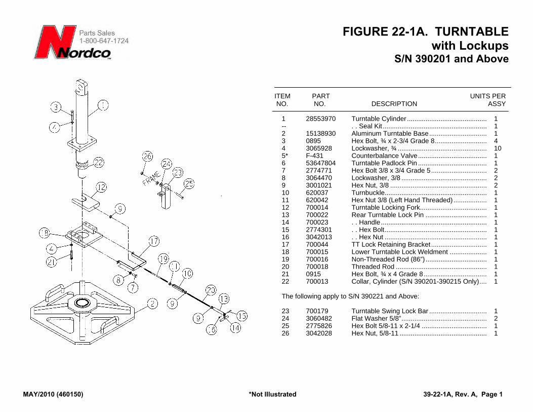
FIGURE 22-1A. TURNTABLE with Lockups
S/N 390201 and Above
MAY/2010 (460150) *Not Illustrated 39-22-1A, Rev. A, Page 1
ITEM PART UNITS PER NO. NO. DESCRIPTION ASSY
1 28553970 Turntable Cylinder ........................................... 1 -- . . Seal Kit ........................................................ 1 2 15138930 Aluminum Turntable Base............................... 1 3 0895 Hex Bolt, ¾ x 2-3/4 Grade 8............................ 4 4 3065928 Lockwasher, ¾ ................................................ 10 5* F-431 Counterbalance Valve..................................... 1 6 53647804 Turntable Padlock Pin ..................................... 1 7 2774771 Hex Bolt 3/8 x 3/4 Grade 5.............................. 2 8 3064470 Lockwasher, 3/8 .............................................. 2 9 3001021 Hex Nut, 3/8 .................................................... 2 10 620037 Turnbuckle....................................................... 1 11 620042 Hex Nut 3/8 (Left Hand Threaded).................. 1 12 700014 Turntable Locking Fork.................................... 1 13 700022 Rear Turntable Lock Pin ................................. 1 14 700023 . . Handle......................................................... 1 15 2774301 . . Hex Bolt....................................................... 1 16 3042013 . . Hex Nut ....................................................... 1 17 700044 TT Lock Retaining Bracket.............................. 1 18 700015 Lower Turntable Lock Weldment .................... 1 19 700016 Non-Threaded Rod (86”) ................................. 1 20 700018 Threaded Rod ................................................. 1 21 0915 Hex Bolt, ¾ x 4 Grade 8.................................. 1 22 700013 Collar, Cylinder (S/N 390201-390215 Only).... 1 The following apply to S/N 390221 and Above: 23 700179 Turntable Swing Lock Bar ............................... 1 24 3060482 Flat Washer 5/8”.............................................. 2 25 2775826 Hex Bolt 5/8-11 x 2-1/4 ................................... 1 26 3042028 Hex Nut, 5/8-11 ............................................... 1