Embed Size (px)
Citation preview
OPERATOR’S
MANUAL
MULTIPLEX SOFTWARE
IDRONAUT Srl
Via Monte Amiata, 10 – 20861 – Brugherio (MB) – ITALY
Tel: +39 039 879656 Fax: +39 039 883382
e-mail: [email protected] web: http://www.idronaut.it

MULTIPLEX SOFTWARE
OPERATOR'S MANUAL
Copyright @ 1982 – 2013 Idronaut S.r.l. All rights reserved.
OCEAN SEVEN and Idronaut are registered trademarks of Idronaut S.r.l.
Other products and services mentioned in this document are identified by the trademarks or service marks of their respective
companies or organisations. No part of this publication, or any software included with it, may be reproduced, stored in a retrieval
system, or transmitted in any form or by any means, including photocopying, electronic, mechanical, recording or otherwise, without
the prior written permission of the copyright holder. Idronaut S.r.l. provides this document as is without warranty of any kind either
expressed or implied including, but not limited to, the implied warranties of merchantability and fitness for a particular purpose.
Idronaut S.r.l. may make changes of improvements in the equipment, software, firmware, or specifications described in this document
at any time and without notice. These changes may be incorporated in new releases of this document. This document may contain
technical inaccuracies or typographical errors. Idronaut S.r.l. waives responsibility of any labour, materials, or costs incurred by any
person or party as a result of using this document. Idronaut S.r.l. shall not be liable for any damages (including, but not limited to,
consequential, indirect or incidental, special damages, or loss of profits or data) even if they were foreseeable and Idronaut S.r.l. has
been informed of their potential occurrence arising out of or in connection with this document or its use.
IDRONAUT Srl Via Monte Amiata, 10 – 20861 – Brugherio (MB) – ITALY
Tel: +39 039 879656 Fax: +39 039 883382
e-mail: [email protected] web: http://www.idronaut.it
IDRONAUT – Brugherio (MB) MULTIPLEX 01-2019
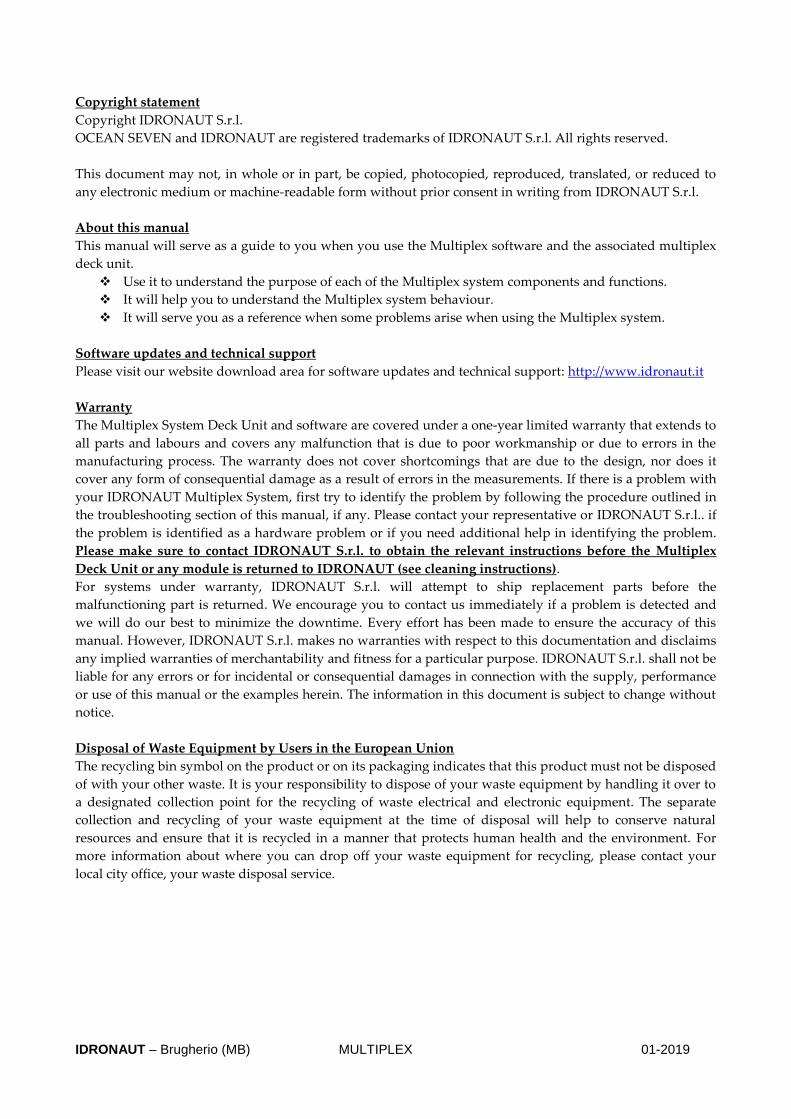
Copyright statement
Copyright IDRONAUT S.r.l.
OCEAN SEVEN and IDRONAUT are registered trademarks of IDRONAUT S.r.l. All rights reserved.
This document may not, in whole or in part, be copied, photocopied, reproduced, translated, or reduced to
any electronic medium or machine-readable form without prior consent in writing from IDRONAUT S.r.l.
About this manual
This manual will serve as a guide to you when you use the Multiplex software and the associated multiplex
deck unit.
❖ Use it to understand the purpose of each of the Multiplex system components and functions.
❖ It will help you to understand the Multiplex system behaviour.
❖ It will serve you as a reference when some problems arise when using the Multiplex system.
Software updates and technical support
Please visit our website download area for software updates and technical support: http://www.idronaut.it
Warranty
The Multiplex System Deck Unit and software are covered under a one-year limited warranty that extends to
all parts and labours and covers any malfunction that is due to poor workmanship or due to errors in the
manufacturing process. The warranty does not cover shortcomings that are due to the design, nor does it
cover any form of consequential damage as a result of errors in the measurements. If there is a problem with
your IDRONAUT Multiplex System, first try to identify the problem by following the procedure outlined in
the troubleshooting section of this manual, if any. Please contact your representative or IDRONAUT S.r.l.. if
the problem is identified as a hardware problem or if you need additional help in identifying the problem.
Please make sure to contact IDRONAUT S.r.l. to obtain the relevant instructions before the Multiplex
Deck Unit or any module is returned to IDRONAUT (see cleaning instructions).
For systems under warranty, IDRONAUT S.r.l. will attempt to ship replacement parts before the
malfunctioning part is returned. We encourage you to contact us immediately if a problem is detected and
we will do our best to minimize the downtime. Every effort has been made to ensure the accuracy of this
manual. However, IDRONAUT S.r.l. makes no warranties with respect to this documentation and disclaims
any implied warranties of merchantability and fitness for a particular purpose. IDRONAUT S.r.l. shall not be
liable for any errors or for incidental or consequential damages in connection with the supply, performance
or use of this manual or the examples herein. The information in this document is subject to change without
notice.
Disposal of Waste Equipment by Users in the European Union
The recycling bin symbol on the product or on its packaging indicates that this product must not be disposed
of with your other waste. It is your responsibility to dispose of your waste equipment by handling it over to
a designated collection point for the recycling of waste electrical and electronic equipment. The separate
collection and recycling of your waste equipment at the time of disposal will help to conserve natural
resources and ensure that it is recycled in a manner that protects human health and the environment. For
more information about where you can drop off your waste equipment for recycling, please contact your
local city office, your waste disposal service.

IDRONAUT – Brugherio (MB) MULTIPLEX 01-2019
TABLE OF CONTENTS
1. INTRODUCTION 5 1.1. OCEAN SEVEN 3xx CTDs 5 2. Start-Up operations 6 2.1. First time start-up 6 2.2. Daily start-up 6 2.2.1. Start a deployment 6 2.2.2. End a deployment 6 3. PROGRAM INSTALLATION 7 3.1. Distributed programmes 7 3.2. PC minimum configuration 7 3.3. ITERM 7 3.4. REDAS5 7 3.5. Multiplex 8 4. MULTIPLEX 9 4.1. menu and functions 9 4.1.1. General setting configuration 10 4.1.2. Data source units configuration 10 4.1.3. Communication channel 11 4.1.4. Extracted data 11 4.2. Data window 12 4.2.1. Data window title 12 4.2.2. Data header 13 4.2.3. Real-time data 13 4.2.4. GPS data window 13 4.3. Data files 13 4.4. Log Multiplex operations 13 5. ITERM PROGRAM 14 5.1. Programme menus and functions 14 5.2. Toolbar 17 5.3. Start-up switches 17 5.4. TOOLS distributed with the ITERM program 17 5.4.1. Interpolate 18 5.4.2. Seawater Fundamental property calculation 18 5.4.3. OS3xx Probe Memory & Battery Endurance 18 6. REDAS5 PROGRAM 20 6.1. Multiplex data file import 20 6.2. Imported data post-processing 20 6.3. Imported data conversion 20 7. OCEAN SEVEN 3xx CTDs cables 21 7.1. OS316Plus/320Plus CTD RS232-C 3m Laboratory Cable 21 7.2. OS305Plus CTD RS232-C 3m Laboratory Cable 22 7.3. 8.5mm Polyurethane submersible cable 23
SECTION ONE - INTRODUCTION 5
IDRONAUT – Brugherio (MB) MULTIPLEX 01-2019
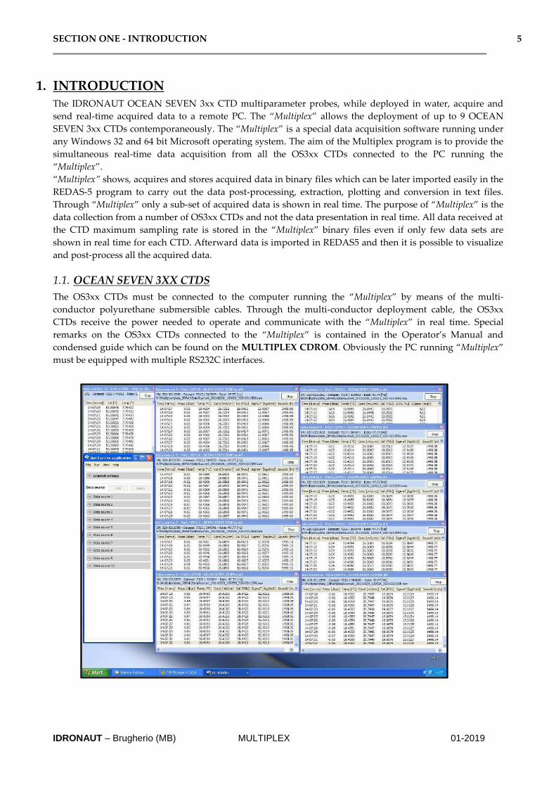
1. INTRODUCTION The IDRONAUT OCEAN SEVEN 3xx CTD multiparameter probes, while deployed in water, acquire and
send real-time acquired data to a remote PC. The “Multiplex” allows the deployment of up to 9 OCEAN
SEVEN 3xx CTDs contemporaneously. The “Multiplex” is a special data acquisition software running under
any Windows 32 and 64 bit Microsoft operating system. The aim of the Multiplex program is to provide the
simultaneous real-time data acquisition from all the OS3xx CTDs connected to the PC running the
“Multiplex”.
“Multiplex” shows, acquires and stores acquired data in binary files which can be later imported easily in the
REDAS-5 program to carry out the data post-processing, extraction, plotting and conversion in text files.
Through “Multiplex” only a sub-set of acquired data is shown in real time. The purpose of “Multiplex” is the
data collection from a number of OS3xx CTDs and not the data presentation in real time. All data received at
the CTD maximum sampling rate is stored in the “Multiplex” binary files even if only few data sets are
shown in real time for each CTD. Afterward data is imported in REDAS5 and then it is possible to visualize
and post-process all the acquired data.
1.1. OCEAN SEVEN 3XX CTDS
The OS3xx CTDs must be connected to the computer running the “Multiplex” by means of the multi-
conductor polyurethane submersible cables. Through the multi-conductor deployment cable, the OS3xx
CTDs receive the power needed to operate and communicate with the “Multiplex” in real time. Special
remarks on the OS3xx CTDs connected to the “Multiplex” is contained in the Operator’s Manual and
condensed guide which can be found on the MULTIPLEX CDROM. Obviously the PC running “Multiplex”
must be equipped with multiple RS232C interfaces.

SECTION TWO – START-UP OPERATIONS 6
IDRONAUT – Brugherio (MB) MULTIPLEX 01-2019
2. Start-Up operations The described start-up procedure implies that the Multiplex, ITERM and REDAS5 programs have been
already installed in the personal computer.
2.1. FIRST TIME START-UP
The step-by-step first set-up after the installation is below described:
1. Run the ITERM program.
2. Connect an OS3xx CTD to the PC RS232C port.
3. Switch on the OS3xx CTD using the CTD top cover on/off rotary switch.
4. OS3xx CTD start-up messages must appear on the ITERM window.
5. Try to control the operations of the CTD through the ITERM and configured connection.
6. Repeat the above sequence of operations for all the OS3xx CTDs, changing each time the
communication port number in the ITERM program.
Note: Multiple instance of ITERM may run all together associated to different communication ports.
2.2. DAILY START-UP
Here are the minimum operations needed to start a deployment of the OS3xx CTDs.
2.2.1. Start a deployment
1. Connect the OS3xx CTDs to the RS232C com. ports.
2. Switch on the OS3xx CTDs positioning the CTD rotary switch on ON.
3. Deploy the OS3xx CTDs in water.
4. Run the “Multiplex” program.
5. Using the “General Setting” configuration, create a new data folder to store acquired data.
6. Enable and/or disable the data sources (OS3xx and GPS) which are not connected to the PC.
7. Check the configuration according to the on-going deployment and start the acquisitions using the
RUN command.
Note: It may be possible that one or more OS3xx CTDs are not immediately initialized after the “START”
acquisition command has been sent from “Multiplex”. In this case, a red message appears on the data window
header (see dedicated section). The “RESTART” button on the data window may be used to carry out another
attempt to initialize and start the CTD acquisition. Before pushing the “RESTART” button, please
always verify that the communication port associated with the OS3xx CTD is correct.
If the OS3xx CTDs are equipped with dissolved oxygen or pH sensors, it is a good practice to carry out a
sensor calibration before starting the deployment. Details about the deployment can be found in the OS3xx
CTDs Operator’s Manual. From time to time, it is a good practice to carry out a pressure sensor offset
calibration (see the details in the OS3xx CTDs Operator’s Manual).
2.2.2. End a deployment
1. Stop acquisition on the “Multiplex” program. Please be aware that, after the data acquisition has
been stopped, it is not possible to close the “Data Source” windows. The “Data Source” windows are
closed when the “Multiplex” program is closed or when a new acquisition starts. The “Data source
windows” may be closed just before hitting the stop command by means of the “Close All
Windows” function available under the “View” menu.
2. Switch off the OS3xx CTDs using the top cover rotary On/Off switch.
3. Import acquired data in REDAS-5 as described in the section dedicated to the REDAS-5 program.

SECTION THREE – PROGRAMs INSTALLATION 7
IDRONAUT – Brugherio (MB) MULTIPLEX 01-2019
3. PROGRAM INSTALLATION This section describes the installation procedure of the programmes distributed with the IDRONAUT
MULTIPLEX CDROM. All programmes are needed to properly operate “Multiplex” and can be installed in
any sequence. They are:
➢ ITERM
➢ REDAS-5
➢ MULTIPLEX
IDRONAUT MULTIPLEX AND REDAS-5 PROGRAMMES ARE NOT PROTECTED
AGAINST MULTIPLE INSTALLATIONS. MULTIPLEX AND REDAS-5 ARE
PROTECTED IN SUCH A WAY THAT THEY CAN BE ONLY USED WITH THE
AUTHORIZED OS3xx CTDs.
3.1. DISTRIBUTED PROGRAMMES
The “MULTIPLEX” CDROM contains folders dedicated to each of the above programs. Each folder contains
the needed set-up files.
CDROM contents:
Multiplex: Multiple CTD and simultaneous Real-time Data Acquisition program.
ITERM: OS3xx CTDs maintenance and communication program.
REDAS5: CTD Real-Time Data Acquisition and data post-processing program.
Literatures & Manuals: IDRONAUT Operator’s Manual, documents etc..
3.2. PC MINIMUM CONFIGURATION
The personal computer needed to run the “Multiplex” must have the following minimum characteristics:
2GHZ Dual Core Intel Processor; 3/4GByte RAM; 128GByte HDD; RS232C Com Ports; CD/DVD RW unit;
22” colours LCD display; High performances video board, 32 or 64bit Windows Operating system.
3.3. ITERM
Copy from the CDROM the “Terminal Emulation” folder to the personal computer hard disk drive. A
shortcut on the desktop can be created pointing to the ITERM.EXE program in the “Terminal Emulation”
folder:
Terminal Emulation folder containing:
ITERM.EXE
ITERM.RTF
|-------→Tools sub-folder
INTERPOLATE.EXE
SWPC.EXE
OS3XXPROBEAUTONOMY.EXE
3.4. REDAS5
Identify and run the “SETUP.EXE” program from the “REDAS5” folder on the CDROM. Follow the on-
screen instructions during the installation.
A shortcut on the desktop can be created pointing to the REDAS5.EXE program in the
“Program\IDRONAUT\REDAS5” windows folder. A dedicated entry in the program menu will be
automatically created.
Windows\Programs\Idronaut\Redas5 folder containing:

SECTION THREE – PROGRAMs INSTALLATION 8
IDRONAUT – Brugherio (MB) MULTIPLEX 01-2019
REDAS5.EXE
Redas5.ico
Splash.bmp
Alarm1.wav
Pause.bmp
Readme.rtf
Readme.txt
Lib.dll
Qtinf70.dll
Record.bmp
Data archive has a fixed folder on the drive “C”. It cannot be changed.
C:\REDASDATA
|-------→ CFG sub-folder
Idtst.cfg
Environ.env
Param.col
Probesn.cod
Splash.bmp
Alarm1.wav
Pause.bmp
Record.bmp
|-------→doc sub-folder
Documentation and help
|-------→Idtst sub-folder
Example data files
|-------→txt sub-folder
Empty folder
3.5. MULTIPLEX
In case the personal computer is not connected to the Internet, before installing the Multiplex program,
verify if the “Microsoft NET Framework 4.0” is correctly installed. Afterwards or if the Internet connection is
available, identify and run the SETUP.EXE program from the “Multiplex” folder on the CD-ROM.
Follow the on-screen instructions during the installation, but we suggest to modify the installation folder to
“C:\Multiplex”. This will simplify the management of the program for non administrator users and the data
import function in REDAS5.
A shortcut on the desktop can be created pointing to the MULTIPLEX.EXE program in the installation
folder. The following folder structure is created on the personal computer at the end of the installation.
Multiplex folder containing:
|-------→ Bin sub-folder
MULTIPLEX.EXE
|----→En-US subfolder
Multiplex.resource.dll
|-------→ Config sub-folder
Defaultconfig.xml
Globalparams.txt
LoggingStatus.config
Probesn.cod (*)
(*) The authorization file must be manually added at the end of the automatic installation procedure
copying it from the CDROM “Aut_File” folder.

SECTION FOUR – MULTIPLEX 9
IDRONAUT – Brugherio (MB) MULTIPLEX 01-2019
4. MULTIPLEX The aim of the Multiplex program is to provide the simultaneous real-time data acquisition from all the
OS3xx CTDs connected to the PC running “Multiplex”.
4.1. MENU AND FUNCTIONS
“Multiplex” has the following menus: File, Run, View, and Help. A short description of any menu functions
follows.
File->Open It opens an existing multiplex configuration file.
File->Save It saves the program configuration.
File->Exit It exits from the programme and closes the communication port and any open data
and configuration files.
Run->Start It initializes the communication with the configured data source units, shows the
data acquisition window and starts to acquire and store in the data file acquired
data.
Acquired data is presented in the data acquisition window according to the
configured data extraction method. Please be aware that data sent from the CTD
“unfiltered” is stored in the “RAW” binary file for the further post-processing
carried out using the REDAS5 program. Therefore, data shown in the dedicated
window (see below) is only a temporary representation and sub-set of the whole
data sent by the OS3xx CTD to “Multiplex” through the PC RS232C com. ports.
Run->Stop It closes the communication with the connected data source units.
View->View All data
window It shows all data window on the computer screen.
View->Close All data
window It closes any open data window present on the computer screen. This command is
available only when the real-time data acquisition is running.
Help->Help It shows the program help (NOT IMPLEMENTED).

SECTION FOUR – MULTIPLEX 10
IDRONAUT – Brugherio (MB) MULTIPLEX 01-2019
Help->About It shows the program information and revision.
4.1.1. General setting configuration
Through the general setting, it is possible to define
the parameters needed by “Multiplex” to
communicate and manage the acquisition from the
configured data sources.
They are:
Config file
It presents the Configuration file name.
Data folder
It selects the data folder where the next acquired data
will be stored.
Save data to txt file
It enables or disables data set save into a txt file.
Data source enabled
It enables or disables the configured data source.
During data acquisition, disabled data source is not
considered.
Data extraction mode
Three different methods are foreseen: Continuous,
Time and Pressure.
Continuous: all received data set will be shown in the
data acquisition window (see below).
Time: every step in seconds, a data set is selected
from the received data set and shown in the data
acquisition window (see below).
Pressure: every step in dbar, a data set is selected from the received data set and shown in the data
acquisition window (see below).
4.1.2. Data source units configuration
It allows the operator to configure the OS3xx CTDs connected to the PC running “Multiplex”.
The following parameters can be
configured:
Description
Short message describing the data source
unit. The description will appear on the
data source window.
Data source type
Two possible data source units are
configurable: OS3xx CTDs or GPS.
Communication channel
See the below dedicated section.
Extracted data
See the below dedicated section.

SECTION FOUR – MULTIPLEX 11
IDRONAUT – Brugherio (MB) MULTIPLEX 01-2019
4.1.3. Communication channel
The communication channel allows the operator
to define the communication port and the
parameters needed to communicate with the
OS3xx CTD or GPS connected with the PC
running “Multiplex”. The communication port
number depends on the Com. Port installed. The
other parameters default values are: 9600, 8,
None, One, None.
4.1.4. Extracted data
The extracted data section allows the operator to
select, among all the possible parameters, the
one that must be shown in real time on the data
window.
The order of parameters cannot be adjusted in
this position; however, it can be freely adjusted
in the data window (see below).
Please only configure the parameters that can be
acquired or derived from the parameters
acquired through the configured/connected OS
3xx CTDs. Selecting a parameter not present or
associable to the OS30xx CTDs may cause
“Multiplex” ill-operation.

SECTION FOUR – MULTIPLEX 12
IDRONAUT – Brugherio (MB) MULTIPLEX 01-2019
4.2. DATA WINDOW
The data window shows acquired data and OS3xx CTD status in real time. A data window for each
configured OS3xx CTD is present. Multiple data windows are possible. Three sections are present in each the
data window: i) the window title; ii)data header; iii)data. Each section of the data window shows the
different information about the ongoing acquisitions.
4.2.1. Data window title
In the data window title are indicated: i) the name and type of the data source unit associated with the
window; ii) the communication port used by the data source; iii) the serial number of the OS3xx CTD
associated with the data window; iv) the name of the “RAW BINARY” data file; v) the sampling rate
(samples per second) received from the data source unit; vi) the number of data frames received since the
start of acquisition; vii) the number of data extracted from the data received according to the configured
extraction method.
Moreover, on the data window title, a push button is present: “STOP”, “RESTART”. Its value depends on
the data source condition. Though this button, it is possible to:
STOP While acquisition is running, it is possible to stop the real-time acquisition from the
data source.
RESTART This command restarts the real-time data acquisition if, during the start-up, there
were any problems to start or if the data acquisition was previously stopped.
Please be aware that restarting the acquisition forces “Multiplex” to create a new
data acquisition file!
Note
In case the acquisition doesn’t start, a red message appears instead of the CTD information on the
data source window title. The acquisition may be started by pressing the RESTART button.
Before pushing the “RESTART” button, please, always verify that the communication port
associated with the OS3xx CTD was properly configured and that the communication cable is
connected.

SECTION FOUR – MULTIPLEX 13
IDRONAUT – Brugherio (MB) MULTIPLEX 01-2019
4.2.2. Data header
The data header section contains the predefined short name and measuring unit associated with each selected parameter. The columns in the data header can be easily aligned by moving them using the mouse. The names which appear on the data header section can be configured by editing the configuration text file contained in the “CONFIG” multiplex installation sub-folder, whose name is “Globalparams.txt”. We strongly suggest creating a backup file before modifying the “GlobalParams.txt” contents.
4.2.3. Real-time data
The data area of the window shows in rows and columns data received from the OS3xx CTDs. The last extracted data rows are shown and remain on the window at the end of the acquisition. The 100 data rows can be easily back-scrolled.
4.2.4. GPS data window Through “Multiplex”, it is possible to acquire the geographical coordinates latitude and longitude. The GPS can be connected to the personal computer running “Multiplex”. Multiplex decodes the GPLL and/or the GPAA sentences to gather the latitude and longitude geographical coordinates. Acquired coordinates are automatically stored in data files together with the data acquired in real time.
Note If the GPS is connected through the PC running “Multiplex”
4.3. DATA FILES Multiplex automatically creates three binary archives during the data acquisition process.
1. “*.RAW” contains all data acquired from the OS3xx CTD. 2. “*.EXT” contains all data acquired from the connected GPS. 3. “*.XFR” contains the information about the OS3xx CTD, its parameters, its calibration coefficients,
etc. Information stored in the “XRF” file is later used by the REDAS5 program during the data file import to create the data header.
The three binary file names are automatically generated by “Multiplex” using the start acquisition date and time and the OS3xx CTD serial number.
4.4. LOG MULTIPLEX OPERATIONS It is possible to force the logging of messages concerning all the “Multiplex” operations. The log file can be later reviewed to analyze any problems met during the field operations. To enable the logging, modify the contents of the file “LoggingStatus.Config” which is stored in the “BIN” folder setting to 1 the log parameter. i.e.: 1= Log, 0= No log.

SECTION FIVE – ITERM PROGRAM 14
IDRONAUT – Brugherio (MB) MULTIPLEX 01-2019
5. ITERM PROGRAM The aim of the ITERM programme is to provide a simple and reliable tool that IDRONAUT customers can
freely use to communicate with their OS3xx CTDs.
5.1. PROGRAMME MENUS AND FUNCTIONS
The ITERM Main Menu has the following items: File, Port, Probe, Transfer, Help. A short description of any
menu and functions follows.
File->Exit It exits from the programme thus closing the communication port and any open files.
Edit->CopySelectionToClipBoard
This function copies the selected text to the Windows operating system clipboard buffer.
Edit->Clear window This function clears the ITERM window.
Port->Set parameters This function allows the operator to set and define the communication port
parameters. Default values for the OS3xx CTDs are: 9600bps, 8bit data, 1stop bit, No
parity, Hardware hand checking: CTS/RTS.

SECTION FIVE – ITERM PROGRAM 15
IDRONAUT – Brugherio (MB) MULTIPLEX 01-2019
Port->Close It closes the communication port and allows the port configuration. When the port is
closed, this command becomes “Open”.
Probe->Identify It identifies the connected probe; information like serial number, hardware and
firmware release is shown on screen in the ITERM program status and title bar. This
function must be performed before running any function in the probe menu. This
function is particularly useful to also switch the probe from “non verbose” mode to
“verbose” mode. At the end of the probe identification, the probe main menu is
shown on the PC screen.
Probe->Upgrade This function allows the operator to verify and, if needed, upgrade through a step-
by-step procedure the probe management firmware. A detailed description of the
OCEAN SEVEN 3xx probe firmware upgrading procedure can be found in the
“Service” section of the relative Operator’s Manual.
Probe->Set Time This function sets up probe time and date. It is possible to select the new probe time
among: GMT, local time or customized date and time.
Probe->Unattended cast n.a.
Probe->StopCast This command concludes an “unattended” data acquisition cycle, which was
previously started using the “Probe->Unattended Cast” command.

SECTION FIVE – ITERM PROGRAM 16
IDRONAUT – Brugherio (MB) MULTIPLEX 01-2019
Probe->UploadCast This function allows the operator to retrieve data stored in the probe memory and to
store it in “Text” files on the PC. The cast uploading is automatically performed by
the program. This function is available only after the probe has been identified using
the Probe Identify function. More than one cast can be selected by using the mouse
and the CTRL or SHIFT keyboard key. “Target directory” must be configured before
starting the upload. After the target directory has been configured and the desired
cast has been selected from the cast list window, the upload button can be pressed.
The programme uploads the probe memory cast by cast. Uploaded data is stored in
text files, a file for each cast.
Probe->Telemetry Test This function allows the operator to perform the test of the probe telemetry interface
by exercising the OCEAN SEVEN 3xx probe non-verbose communication protocol.
The test can be used to verify the RS232C connection too.
Tx test This test verifies telemetry by sending commands to the connected probe.
Rx test This test verifies telemetry by instructing the connected probe to continuously send
acquired data. The Rx test is useful to perform the fine-tuning of the telemetry Deck
Unit transceiver modem.
Aspect->Font This function allows the operator to decide the type of font to be used to show
messages on the terminal window.
Aspect->Colour This function allows the operator to select the foreground and background colours
SECTION FIVE – ITERM PROGRAM 17
IDRONAUT – Brugherio (MB) MULTIPLEX 01-2019
among a list of possible choices.
Transfer->SendTextFile This function allows the operator to transfer a text file to the PROBE connected
through the serial port.
Transfer->CaptureToFile This function captures the characters received and sent through the serial port to a
text file. The operator can select the file name and folder. By invoking this function,
once ITERM is capturing, the character stops capturing and returns to the standard
operations.
Help->Contents It shows this help file.
Help->About It shows notice about the ITERM programme release.
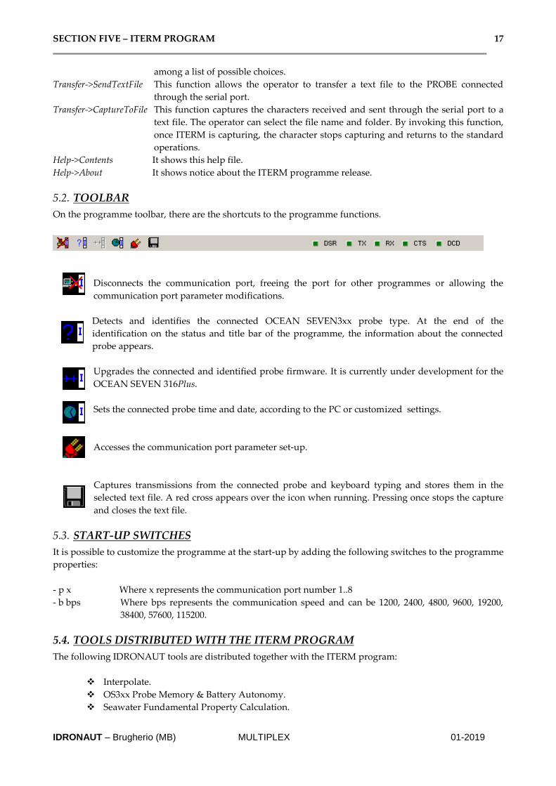
5.2. TOOLBAR
On the programme toolbar, there are the shortcuts to the programme functions.
Disconnects the communication port, freeing the port for other programmes or allowing the
communication port parameter modifications.
Detects and identifies the connected OCEAN SEVEN3xx probe type. At the end of the
identification on the status and title bar of the programme, the information about the connected
probe appears.
Upgrades the connected and identified probe firmware. It is currently under development for the
OCEAN SEVEN 316Plus.
Sets the connected probe time and date, according to the PC or customized settings.
Accesses the communication port parameter set-up.
Captures transmissions from the connected probe and keyboard typing and stores them in the
selected text file. A red cross appears over the icon when running. Pressing once stops the capture
and closes the text file.
5.3. START-UP SWITCHES
It is possible to customize the programme at the start-up by adding the following switches to the programme
properties:
- p x Where x represents the communication port number 1..8
- b bps Where bps represents the communication speed and can be 1200, 2400, 4800, 9600, 19200,
38400, 57600, 115200.
5.4. TOOLS DISTRIBUTED WITH THE ITERM PROGRAM
The following IDRONAUT tools are distributed together with the ITERM program:
❖ Interpolate.
❖ OS3xx Probe Memory & Battery Autonomy.
❖ Seawater Fundamental Property Calculation.

SECTION FIVE – ITERM PROGRAM 18
IDRONAUT – Brugherio (MB) MULTIPLEX 01-2019
5.4.1. Interpolate
This program allows calculating “a” and “b” coefficients (slope and offset) to interpolate a set of 10 tabbed
data (see picture) using: linear, logarithmic or exponential interpolation technique.
5.4.2. Seawater Fundamental property calculation
This tool allows the probe to calculate the most important fundamental properties of seawater. Through a
very simple interface, the operator can enter the Temperature, Conductivity and Pressure sensor values and
calculate the derived parameters instantaneously. Calculation is performed using the UNESCO formulae
and recommendations.
5.4.3. OS3xx Probe Memory & Battery Endurance
The internal probe battery endurance can be easily calculated using the “Os3xxProbeAutonomy” tool, which
is distributed with the ITERM program and the REDAS-5 program. This tool, through a simplified user
interface (see below), allows the operator to select the probe type, select the sensors interfaced by the probe
and afterwards calculate the probe battery and data recording autonomy.

SECTION FIVE – ITERM PROGRAM 19
IDRONAUT – Brugherio (MB) MULTIPLEX 01-2019

SECTION SIX – REDAS5 PROGRAM 20
IDRONAUT – Brugherio (MB) MULTIPLEX 01-2019
6. REDAS5 PROGRAM Documentation about the REDAS5 program installation, start-up and use can be found in the dedicated
REDAS-5 Operator’s Manual on the “Multiplex & REDAS5” CDROM.
6.1. MULTIPLEX DATA FILE IMPORT
Multiplex generates one binary file for each OS3xx CTD interfaced. The only possibility to process, visualize,
plot and convert the acquired data into text files is to import these files using the REDAS5 program.
A dedicated command under the REDAS5 “FILE->IMPORT” menu easily allows selecting the binary file
from the Multiplex program data folder and importing it by assigning to a cruise database. The philosophy
about the cruise data base is responsibility of the operator. For instance acquired data can be assigned to a
“Cruise data base” for each OS3xx CTD; or it can be assigned to single “Cruise data base” for each sampling
point; or it can be organized per day, per month, etc...
In case the GPS is connected to the Multiplex program, it is mandatory to enable the “Latitude & Longitude”
check mark under the ENVIRONENT->NMEA tab. This set-up “informs” the REDAS5 that data files to
import are completed with the GPS information.
AT THE END OF DATA IMPORT, REDAS5 AUTOMATICALLY DELETES THE
ORGINAL MULTIPLEX BINARY FILES. WE STRONGLY SUGGEST THAT YOU
CARRY OUT A BACKUP OF THE MULTIPLEX ACQUIRED DATA FILE BEFORE
IMPORTING THEM IN REDAS-5.
Note: If data files are imported without the correct environment set-up, GPS information is ignored.
6.2. IMPORTED DATA POST-PROCESSING
Once data is imported in the REDAS5 database, it can be post-processed, plotted, exported according to the
desired method. We suggest having a look at the screen capture sequences which describe the REDAS5 data
post-processing and that can be found on the IDRONAUT CD-ROM under the “Literature &
Documentation” folder.
6.3. IMPORTED DATA CONVERSION
Data imported in REDAS5 can be easily converted into text files. Text file contents and format can be freely
and easily configured using the REDAS5 configuration command. We suggest having a look at the screen
capture sequences which describe the REDAS5 configuration and export to text file that can be found on the
IDRONAUT CD-ROM under the “Literature & Documentation” folder.

SECTION SEVEN – OS3xx CTDs cables 21
IDRONAUT – Brugherio (MB) MULTIPLEX 01-2019
7. OCEAN SEVEN 3xx CTDs cables
7.1. OS316PLUS/320PLUS CTD RS232-C 3M LABORATORY CABLE
SECTION SEVEN – OS3xx CTDs cables 22
IDRONAUT – Brugherio (MB) MULTIPLEX 01-2019
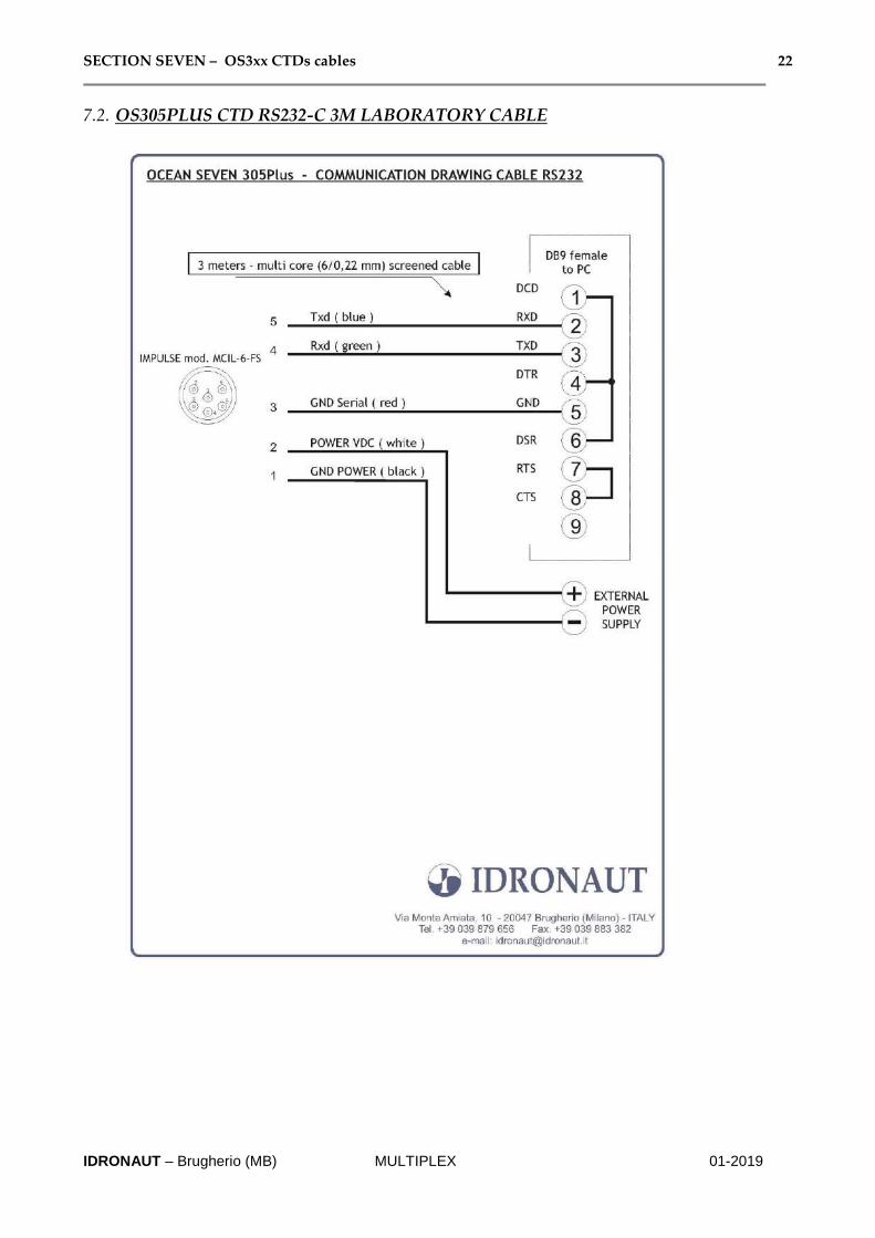
7.2. OS305PLUS CTD RS232-C 3M LABORATORY CABLE

SECTION SEVEN – OS3xx CTDs cables 23
IDRONAUT – Brugherio (MB) MULTIPLEX 01-2019
7.3. 8.5MM POLYURETHANE SUBMERSIBLE CABLE
200m of the below cable is provided on a plastic reel, completed with the connectors needed to connect the
OCEAN SEVEN 3xx CTDs to the Multiplex Deck Unit.
CONSTRUCTION DETAILS
➢ 2 X 19 AWG: Tinned copper conductor 42x0,15 mm Cross-linked polyethylene insulation,
nominal thickness 0,50 mm, nominal diameter 2,10 mm, colors red, black.
➢ 2 X 2 X 24 AWG: Tinned copper conductor 19x0,13 mm Polypropylene insulation,
nominal thickness 0,25 mm, nominal diameter 1,15 mmCores twisted in pairs colors
white/blue, grey/orange
➢ Elements laid up together with polypropylene filling yarn
➢ Protective non woven tape
➢ Tinned copper braid overall shield, wire diameter 0,10 mm, coverage 85%
➢ Protective non woven tape
➢ Aramidic yarn braid
➢ Hydrolysis resistant PUR outer sheath, nominal thickness 1,10 mm, colours orange
➢ Nominal overall diameter 8,30 mm
➢ Metric marking : “ IDRONAUT – MILANO - ….meters) ”
ELECTRICAL AND PHYSICAL CHARACTERISTICS
Electrical resistance conductors 19 AWG: < 26,70 ohm/km @ 20°C
Electrical resistance conductors 24 AWG: < 88,6 ohm/km @ 20°C
Nominal mutual capacitance (24 AWG) : 60 pF/m
Nominal impedance @ 1 MHz (24 AWG) : 93 ohm
Attenuation @ 1 MHz(24 AWG): < 2 dB/100 m
Insulation resistance: > 1000 Mohm*km @ 20° C
Working voltage : 600 V
OTHER CHARACTERISTICS
Weight in air : 96 kg/km
Weight in seawater : 36 kg/km
Breaking strength : > 250 kg
Bending radius static min. : 50 mm
Bending radius flexing min. : 100 mm
Working temperature : -40/+80 °C