Embed Size (px)
Citation preview
1/47
LANCER LSS SERIES
OPERATOR MANUAL
Rev Date / Rev No: 2016.11.10/Rev3 Item No: Lancer LSS Doc- 01-EN
2/47
Content
1. PRESENTATION .................................................................................................................................................................................................................... 5
1.1 INTRODUCTION OF THE COMPANY ....................................................................................................................................................................... 5
1.2 RESPONSIBILITY OF THE MANUFACTURER ............................................................................................................................................................. 6
1.3. CLASSIFICATION .......................................................................................................................................................................................................... 6
1.4. LIFE TIME OF TH E PRODUCT .................................................................................................................................................................................. 6
2. INTRODUCTION .................................................................................................................................................................................................................... 6
2.1 REFERANCE STANDARDS .............................................................................................................................................................................................. 6
2.1. USE AND STORAGE OF THE OPERATING MANUAL ........................................................................................................................................... 7
2.2. MARKINGS AND WARNINGS IN THE OPERATING MANUAL ............................................................................................................................. 8
2.3 OBTAINING A NEW OPERATING MANUAL .................................................................................................................................................................. 8
4. SAFETY ................................................................................................................................................................................................................................... 9
4.1 GENERAL SAFETY PRECAUTIONS ........................................................................................................................................................................ 9
4.2. INTENDED USE ........................................................................................................................................................................................................... 10
4.3 SAFETY EQUIPMENT ...................................................................................................................................................................................................... 10
4.4 POTENTIAL RISKS DURING OPERATION .................................................................................................................................................................. 11
4.5. SAFETY MARKINGS ON THE PRODUCT .............................................................................................................................................................. 11
4.6 PERSONAL PROTECTIVE EQUIPMENT ..................................................................................................................................................................... 12
4.7. SOUND LEVEL ................................................................................................................................................................................................................. 12
5. DESCRIPTION OF THE UNIT............................................................................................................................................................................................ 13
5.1 DESCRIPTION OF THE PRODUCT .............................................................................................................................................................................. 13

3/47
5.2 GENERAL COMPONENTS ........................................................................................................................................................................................ 13
Emergency Stop Button ........................................................................................................................................................................................................... 13
5.3. CHAMBER CAPACITY and EXTERNAL DIMENSIONS OF STERILIZERS ...................................................................................................... 15
5.4 TECHNICAL DATA ....................................................................................................................................................................................................... 16
5.5. SAMPLE SERIAL NUMBER PLATE.............................................................................................................................................................................. 17
6. INSTALLATION ..................................................................................................................................................................................................................... 18
6.1 CONTENTS OF PACKAGE ............................................................................................................................................................................................. 18
6.2 OPERATING ENVIRONMENT AND POSITIONING OF THE STERILIZER ...................................................................................................... 19
6.3. INSTALLATION OF THE STERILIZER ..................................................................................................................................................................... 20
7. WATER QUALITY ................................................................................................................................................................................................................ 24
8. ELECTRONIC CONTROL UNIT ........................................................................................................................................................................................ 26
8.1 USING THE PROGRAMS AND THE CONTROL PANEL ..................................................................................................................................... 26
8.2 PROGRAMS AND USE ............................................................................................................................................................................................... 26
8.3 PLC CONTROL ............................................................................................................................................................................................................. 27
8.4 SELECTION OF PROGRAMS ................................................................................................................................................................................... 30
8.4.1 Program Details .......................................................................................................................................................................................................... 31
8.5 RUNNING A PROGRAM ............................................................................................................................................................................................. 34
8.6 PANEL PRINTER ......................................................................................................................................................................................................... 35
8.7 REPLACING THE PRINTER PAPER ........................................................................................................................................................................ 36
9. INTERLOCK SYSTEM ......................................................................................................................................................................................................... 37
9.1 Media Interlock ......................................................................................................................................................................................................................... 37

4/47
9.2. Door Interlock ........................................................................................................................................................................................................................... 38
10. MAINTENANCE ................................................................................................................................................................................................................ 42
10.1 ROUTINE MAINTENANCE ............................................................................................................................................................................................ 42
10.2. PERIODIC MAINTENANCE Daily Maintenance .................................................................................................................................................. 42
10.3. EXTRAORDINARY MAINTENANCE..................................................................................................................................................................... 44
10.4. CLEANING ................................................................................................................................................................................................................. 44
10.5. RUSTING ................................................................................................................................................................................................................... 45
11. PACKING LIST ................................................................................................................................................................................................................. 46
12. MAXIMUM LOADING CAPACITY .................................................................................................................................................................................. 47
5/47
1. PRESENTATION
READ ALL INSTRUCTIONS INCLUDING WARNING PAPER!
1.1 INTRODUCTION OF THE COMPANY
Our company was incorporated in 1984, and has been one of the leading companies in the Medical Equipment Industry. From the beginning of 2004, it has been concentrated on CE certification activities, using the experience of our partner in ISO 9001:2008, ISO 13485:2012 and CE Certifications due to standardization which has been gaining importance in the Health Care Industry, European Union Harmonization Process of Turkey, etc. The company is currently Quality Management System certified.
Trans Medikal has already completed all Product Standards relating to the Steam Sterilizer it manufactures: Directive on Pressure Equipment (2014/68/EU) – Approval of PED Documentation, Electromagnetic Compatibility Tests (EN 60601-1-2), Electrical Safety Tests (EN 60601-1), New Design and plans to proceed with Standard Product Manufacturing from 2005 after completing CE Certification Process.
Please contact us at the following address, phone and e-mail for further information about our company and products.
PRODUCTION FACILITY ADDRESS
TRANS MEDİKAL ALETLER SAN. VE TİC. A.Ş.
Phone : +90 (0312) 385 77 20 Fax : +90(0312 ) 385 25 50
Web : www.tr ansmedikal.com
e-mail : [email protected]
Address:Ahi Evran OSB Mah. Kırımhanlığı Cad. No:6A 1 Sincan Ankara /TURKEY
6/47
1.2 RESPONSIBILITY OF THE MANUFACTURER
As a manufacturer, our company, carries out renewal, replacement, repair – maintenance and calibration of all devices and equipment it supplies and manufactures, through its authorized personnel or authorized agent, by using equipment it declares to be suitable for the products and compatible with gas and electrical installations, air circulation and temperature for the location where such products are used. Our company is responsible for reliability, safety and performance of the devices.
1.3. CLASSIFICATION
1.4. LIFE TIME OF TH E PRODUCT
The life cycle of the steam sterilizer is expected to be 10 years and/or 10000 cycle as determined by the PED directive
Never use the steam sterilizer before the electrical performance and mechanical performance tests are carried out by authorised technical personnel of Trans Medikal Aletler San. ve Tic. A.Ş.
2. INTRODUCTION
2.1 REFERANCE STANDARDS
The Steam Sterilizer meets the requirements of Machinery Directive, RoHs, Compliance and Pressure Equipment Directive PED (2014/68/EU) and complies with the relevant standards.
2.2 STAFF REQUIREMENTS
The authorized operators and the service personnel should have the following qualifications:
1. General knowledge to understand the contents of this operating manual;
2. Sufficient information about the Sterilizer and its installation;

7/47
3. Knowledge of Health Care, Accident Prevention and Technical Progress;
The persons to use and service the device are specified below:
OPERATOR:
The person who uses the device in accordance with its intended use.
AUTHORIZED PERSON:
The person or group of persons, who will provide the operator with training on operation, technical service and routine maintenance of the sterilizer. The authorized person is the person who is responsible for installation, operation and use of the device.
2.1. USE AND STORAGE OF THE OPERATING MANUAL
Purpose: This manual is an integral part of the device, and it is recommended that this manual should be made available near the sterilizer for quick and easy access. You can have access to the following information in this manual.
• Correct installation; Safe and effective use of the sterilizer; Continuous and routine maintenance;
The sterilizer should only be used as described in the Operating Manual. It should not be used for purposes other than its intended use. Occupational Health and Safety regulations should be known and complied with at the site where the sterilizer is installed.
The Operating Manual should be kept in a safe place where it is easily accessible for all speaking personnel. Care should be taken when using the manual to keep it clean and free from damage. It is strictly prohibited to delete, revise or modify the contents of the Operating Manual.
Drawings or documents accompanying the sterilizer should not be given to third persons. The copyright on all such documents belongs to TRANS MEDİKAL ALETLER SAN. VE TİC. A.Ş.
It is strictly prohibited to photocopy this Operating Manual partly or as a whole.

8/47
TRANS MEDİKAL ALETLER SAN. VE TİC. A.Ş. reserves the right to revise or develop the information contained in this Operating Manual.
If the sterilizer is sold through an intermediary, the Operating Manual should be supplied with the sterilizer. In such case, the manufacturer should be informed of the new purchaser.
2.2. MARKINGS AND WARNINGS IN THE OPERATING MANUAL
SYMBOL DESCRIPTION Strictly Prohibited This mark indicates that respective action should never be taken. Careless action may cause serious damage to the operator or sterilizer.
2.3 OBTAINING A NEW OPERATING MANUAL
If your Operating Manual is lost or damaged for any reason, you can obtain a new copy by providing the following information.
1. Name and Model of the sterilizer
2. Address and Person to which the new Operating Manual is to be sent. Please send the Name and Model you need to the followingaddress.
PRODUCTION FACILITY ADDRESS
TRANS MEDİKAL ALETLER SAN. VE TİC. A.Ş. Adress : Ahi Evran OSB Mah.
Kırımhanlığı Cad. No: 6A 1 Sincan Ankara/TURKEY
Phone : +90 (0312) 385 77 20 Fax : +90(0312) 385 71 00
Web : www.transmedikal.com e-mail : [email protected]
9/47
4. SAFETY
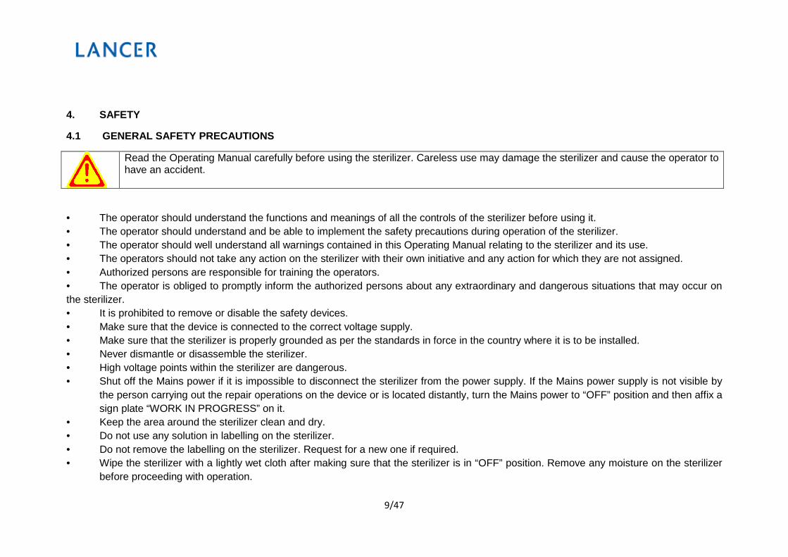
4.1 GENERAL SAFETY PRECAUTIONS
Read the Operating Manual carefully before using the sterilizer. Careless use may damage the sterilizer and cause the operator to have an accident.
• The operator should understand the functions and meanings of all the controls of the sterilizer before using it.• The operator should understand and be able to implement the safety precautions during operation of the sterilizer.• The operator should well understand all warnings contained in this Operating Manual relating to the sterilizer and its use.• The operators should not take any action on the sterilizer with their own initiative and any action for which they are not assigned.• Authorized persons are responsible for training the operators.• The operator is obliged to promptly inform the authorized persons about any extraordinary and dangerous situations that may occur onthe sterilizer. • It is prohibited to remove or disable the safety devices.• Make sure that the device is connected to the correct voltage supply.• Make sure that the sterilizer is properly grounded as per the standards in force in the country where it is to be installed.• Never dismantle or disassemble the sterilizer.• High voltage points within the sterilizer are dangerous.• Shut off the Mains power if it is impossible to disconnect the sterilizer from the power supply. If the Mains power supply is not visible by
the person carrying out the repair operations on the device or is located distantly, turn the Mains power to “OFF” position and then affix asign plate “WORK IN PROGRESS” on it.
• Keep the area around the sterilizer clean and dry.• Do not use any solution in labelling on the sterilizer.• Do not remove the labelling on the sterilizer. Request for a new one if required.• Wipe the sterilizer with a lightly wet cloth after making sure that the sterilizer is in “OFF” position. Remove any moisture on the sterilizer
before proceeding with operation.
10/47
• Do not pour water or any other liquid on the sterilizer. It may cause short circuits or rusting of the sterilizer.• Do not touch the device with wet hands. Follow the safety precautions for use of electrical appliances if your hands are wet.• The sterilizer is not designed to operate in environments where any gas or explosive steams exist.• Any explosions or strong vibrations that do not expose the device to mechanical effects.• Do not stand in front of the door while opening it. The steam that will escape when the door is opened may cause injury.• Empty the water contained in the sterilizer when handling it from one location to another.
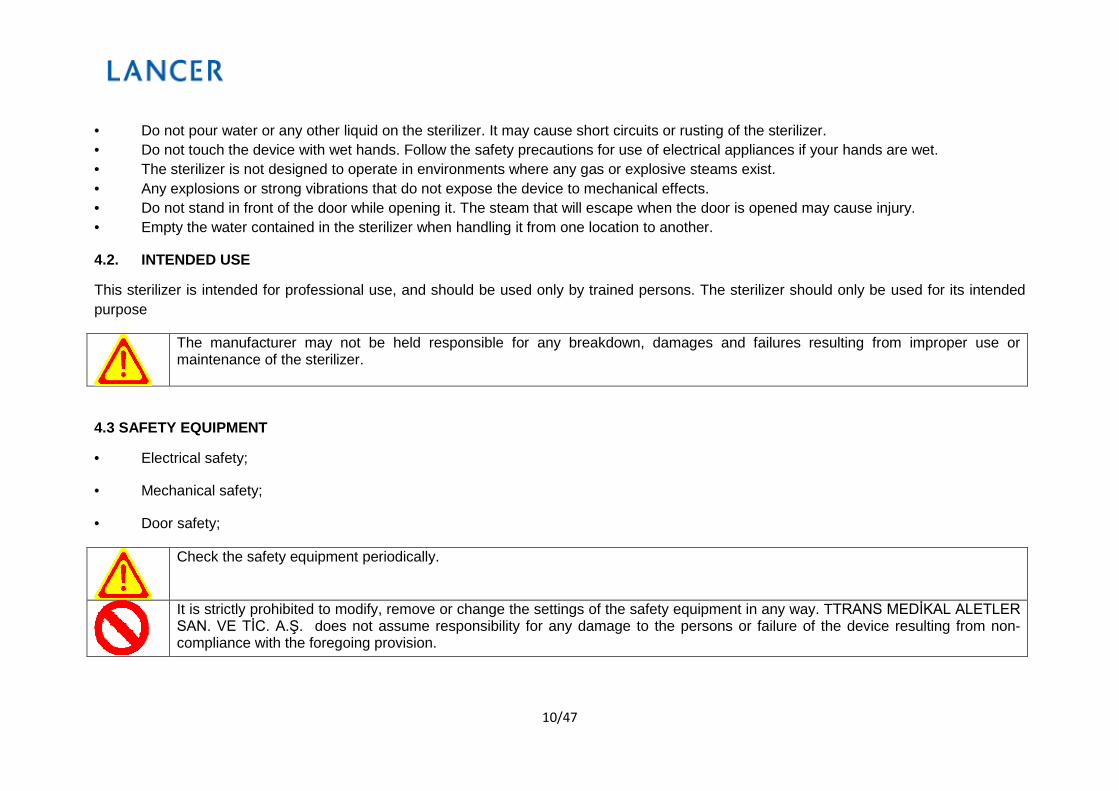
4.2. INTENDED USE
This sterilizer is intended for professional use, and should be used only by trained persons. The sterilizer should only be used for its intended purpose
The manufacturer may not be held responsible for any breakdown, damages and failures resulting from improper use or maintenance of the sterilizer.
4.3 SAFETY EQUIPMENT
• Electrical safety;
• Mechanical safety;
• Door safety;
Check the safety equipment periodically.
It is strictly prohibited to modify, remove or change the settings of the safety equipment in any way. TTRANS MEDİKAL ALETLER SAN. VE TİC. A.Ş. does not assume responsibility for any damage to the persons or failure of the device resulting from non-compliance with the foregoing provision.

11/47
4.4 POTENTIAL RISKS DURING OPERATION
The operator is under some inherent risks during normal operation of the device.
- Burn Hazard
The door of the sterilizer is opened to take the item inside the sterilizer when the sterilization program ends, and at this time the inner side of the chamber will still be hot. Be careful about the hot air flowing out of the chamber. When the door is first opened, do not stand in front of the door, otherwise the hot steam may cause damage.
As the equipment contained in the chamber is also hot, do not touch the surface of the chamber or accessories in it.
4.5. SAFETY MARKINGS ON THE PRODUCT Sign Explanation
Shows the 380V AC electricity.
Shows the main 380V AC plug of the device.
380VAC Main Input
380VAC

12/47
Indicates that this surface is hot.
Earth line.
Warning unauthorized staff.
These Marks Should Not Be Removed, Scratched Or Damaged.
4.6 PERSONAL PROTECTIVE EQUIPMENT
Latex Protective Glasses Gloves
4.7. SOUND LEVEL
Average Sound Level is 80 db.

13/47
5. DESCRIPTION OF THE UNIT5.1 DESCRIPTION OF THE PRODUCT Lancer LSS Series Steam Sterilizer is designed for laboratory use. The sterilization temperature 121˚C, water liquids can be sterilized within this temperature by selecting respective validated programs.
The microprocessor included in the system controls each of such sterilization processes, and ensures that necessary cycles are executed. All processes are recorded for documentation purposes trough instant printout by means of a panel printer used.
The steam sterilizers manufactured in the following capacities may be divided into two groups, as single-door and double-door. In case of the double- door model, the model title is followed by “-S” indicating double door.
Loading and unloading of the single-door steam sterilizer is effected through the door where the control unit is located.
5.2 GENERAL COMPONENTS
Emergency Stop Button
• Check that the emergency stop button is in off position. (You can check it by turning the emergency stop button in the arrow direction.)• When pressing the button, all applications are cut off in the sterilizer.
Power Switch Place the power switch in 1 position.

14/47
Device Parameters on control side
Chamber Pressure Manometer
Steam Supply Pressure Manometer
Emergency switch
Power switch
Electronic Control Panel Printer
Sliding Door
*The manufacturer reserves the right to change the design of the device.
15/47
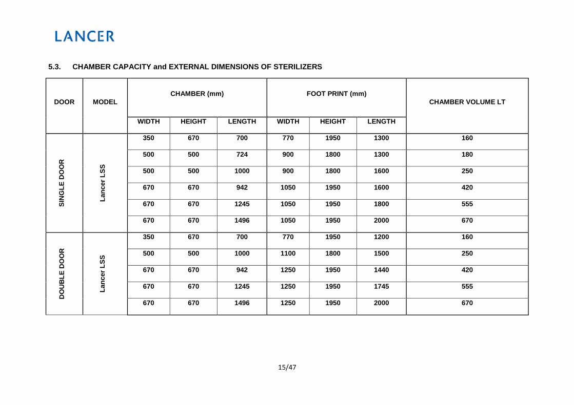
5.3. CHAMBER CAPACITY and EXTERNAL DIMENSIONS OF STERILIZERS
DOOR MODEL CHAMBER (mm) FOOT PRINT (mm)
CHAMBER VOLUME LT
WIDTH HEIGHT LENGTH WIDTH HEIGHT LENGTH
SIN
GLE
DO
OR
Lanc
er L
SS
350 670 700 770 1950 1300 160
500 500 724 900 1800 1300 180
500 500 1000 900 1800 1600 250
670 670 942 1050 1950 1600 420
670 670 1245 1050 1950 1800 555
670 670 1496 1050 1950 2000 670
DO
UB
LE D
OO
R
Lanc
er L
SS
350 670 700 770 1950 1200 160
500 500 1000 1100 1800 1500 250
670 670 942 1250 1950 1440 420
670 670 1245 1250 1950 1745 555
670 670 1496 1250 1950 2000 670

16/47
5.4 TECHNICAL DATA
Voltage 220 / 380 VAC
Frequency 50 / 60 Hz
Sterilization Cycles STERILIZATION PROGRAM
Control Cycles BOWIE-DICK TEST AIR LEAKAGE TEST
Range of environmental conditions in which the unit was designed to operate
Indoor use, Temperature +5 … +40 oCMax. Relative Humidity: 85%, Max. Variation in mains voltage : ±10%
Maximum Pressure 3 bar
Printer YES
17/47
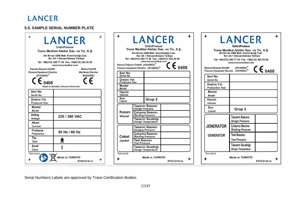
5.5. SAMPLE SERIAL NUMBER PLATE
Serial Numbers Labels are approved by Trans Certification Bodies.
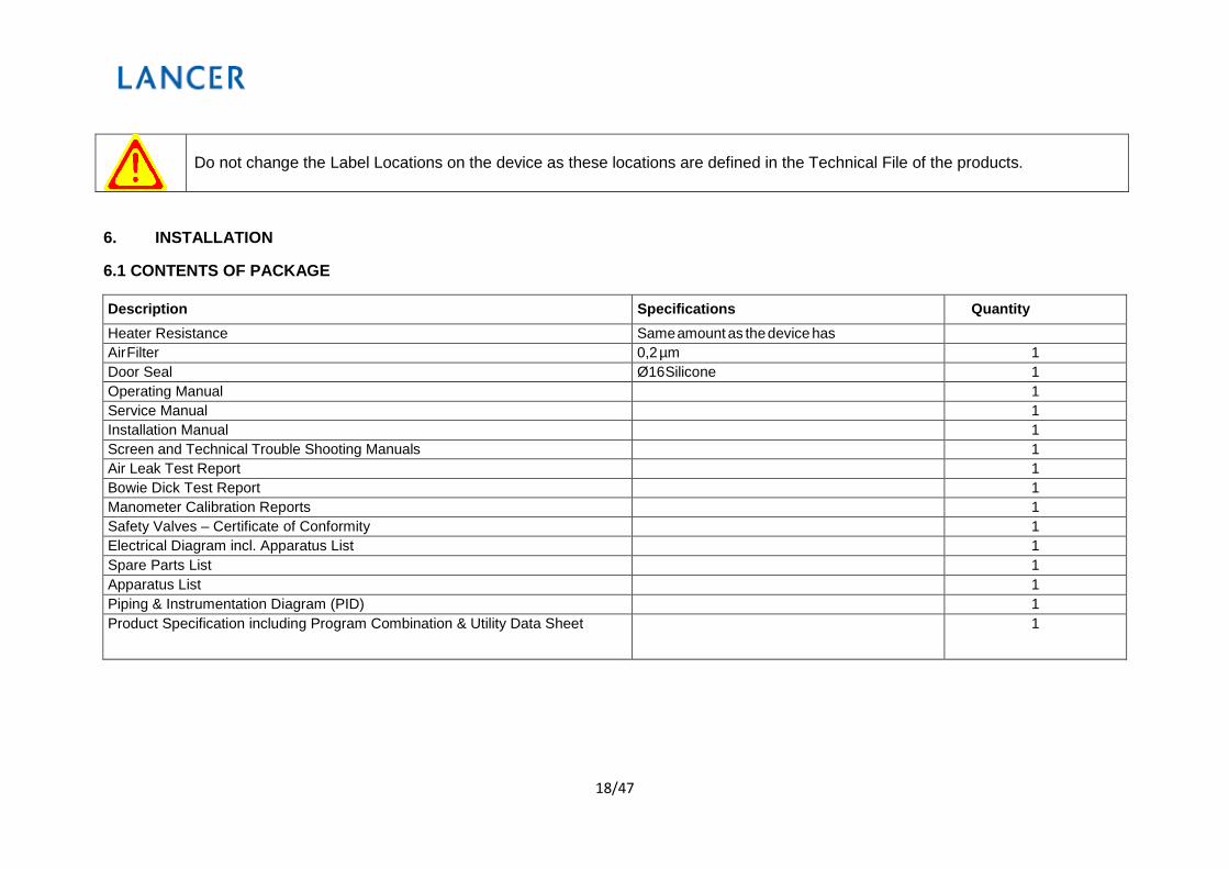
18/47
Do not change the Label Locations on the device as these locations are defined in the Technical File of the products.
6. INSTALLATION
6.1 CONTENTS OF PACKAGE
Description Specifications Quantity
Heater Resistance Same amount as the device has Air Filter 0,2 µm 1 Door Seal Ø16 Silicone 1 Operating Manual 1 Service Manual 1 Installation Manual 1 Screen and Technical Trouble Shooting Manuals 1 Air Leak Test Report 1 Bowie Dick Test Report 1 Manometer Calibration Reports 1 Safety Valves – Certificate of Conformity 1 Electrical Diagram incl. Apparatus List 1 Spare Parts List 1 Apparatus List 1 Piping & Instrumentation Diagram (PID) 1 Product Specification including Program Combination & Utility Data Sheet 1

19/47
6.2 OPERATING ENVIRONMENT AND POSITIONING OF THE STERILIZER
• The sterilizer should be installed in an area where only authorized users can access.
• Do not install the sterilizer near steam sources and at locations where there is a risk of water splash. Water may cause short circuit and failure in the internal electronic circuitry.
• Use the sterilizer at a location provided with proper air circulation.
• Do not use the sterilizer at locations near heat sources.
• The area where the sterilizer is to be installed and used should be illuminated according to the standard UNI10380.
• The correct room conditions for opening the device require a temperature between 5-40 oC and humidity of 85% (non-condensing).
20/47
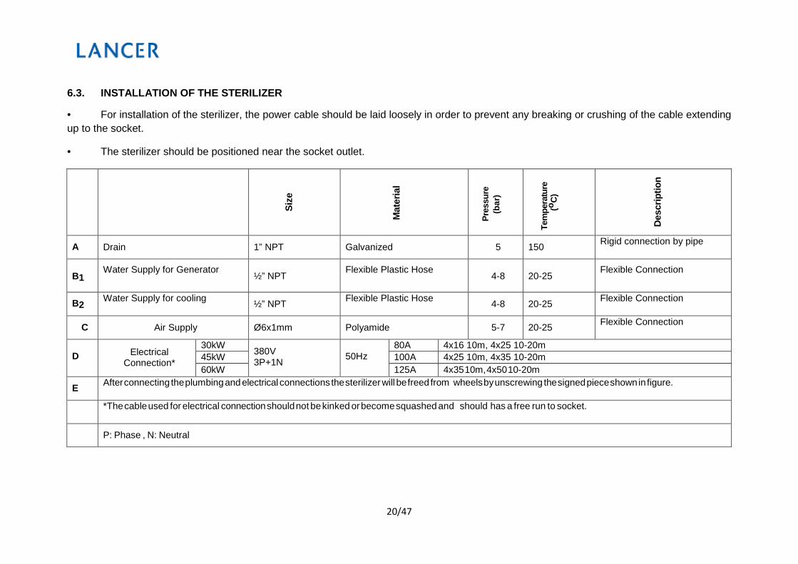
6.3. INSTALLATION OF THE STERILIZER
• For installation of the sterilizer, the power cable should be laid loosely in order to prevent any breaking or crushing of the cable extending up to the socket.
• The sterilizer should be positioned near the socket outlet.
Si
ze
Mat
eria
l
Pr
essu
re
(bar
)
Tem
pera
ture
(o
C)
D
escr
iptio
n
A Drain 1” NPT Galvanized 5 150 Rigid connection by pipe
B1
Water Supply for Generator ½” NPT
Flexible Plastic Hose 4-8
20-25
Flexible Connection
B2 Water Supply for cooling ½” NPT Flexible Plastic Hose 4-8 20-25 Flexible Connection
C Air Supply Ø6x1mm Polyamide 5-7 20-25 Flexible Connection
D Electrical
Connection*
30kW 380V 3P+1N
50Hz
80A 4x16 10m, 4x25 10-20m 45kW 100A 4x25 10m, 4x35 10-20m 60kW 125A 4x35 10m, 4x50 10-20m
E After connecting the plumbing and electrical connections the sterilizer will be freed from wheels by unscrewing the signed piece shown in figure.
*The cable used for electrical connection should not be kinked or become squashed and should has a free run to socket.
P: Phase , N: Neutral
21/47
Installation Steps Of The Sterilizer
For the transportation, the sterilizer should be lifted by a crane and loaded on to transportation vehicle. The sterilizer has to be lifted from the two lifting pieces, by two hooks of the crane, which are welded on to the chamber. After taking the sterilizer down to the ground, you should unscrew the ground fixing screws to make the sterilizer moveable. After moving the sterilizer to the place that it will be used, assemble the plumbing and then fix the sterilizer on the ground by fixing
screws. Then connect the sterilizer to the power supply.
When lifting the sterilizer, never use a single hook but always lift from both of the two hooks. Otherwise the Sterilizer may fall and subsequently cause serious damage to people or the environment.
The hooks that will be used for lifting the sterilizer must have a locking mechanism for the device not to get free from the hooks
Choosing the Installation Area
The device should be balanced during the installation. The Sterilizer should be installed onto even floors. The room or area where the sterilizer is installed should be well ventilated when the sterilizer is in operation. The room or area where the sterilizer is installed should be big enough for easy access to load and unload the machine. After the installation of the sterilizer, there should be about 70 cm of space on each side of the sterilizer ( this space is important for
performing technical maintenance ).
22/47
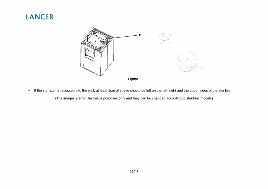
Figure
If the sterilizer is recessed into the wall, at least 1cm of space should be left on the left, right and the upper sides of the sterilizer
(The images are for illustrative purposes only and they can be changed according to sterilizer models)
E

23/47
Figure.1.Installation diagrams for Sterilizers in front of the Wall
Figure.2.Installationdiagramsfor Sterilizers
(The images are for illustrative purposes only and they can be changed according to sterilizer models)
Double sliding door Loading side
Double sliding door Unloading side

24/47
7. WATER QUALITY
The quality of water to be used for steam sterilizer must be as in the following:
Condensate water
Supplywater
Evaporation residue ≤ 1,0 mg/kg ≤ 10 mg/l Silicium Oxide, SiO2 ≤ 0,1 mg/kg ≤ 1 mg/l Iron ≤ 0,1 mg/kg ≤ 0,2 mg/l Cadmium ≤ 0,005 mg/kg ≤ 0,005 mg/l Lead ≤ 0,05 mg/kg ≤ 0,05 mg/l Heavy metals other than Iron, Cadmium, Lead ≤ 0,1 mg/kg ≤ 0,1 mg/l Chloride (Cl’) ≤ 0,1 mg/kg ≤ 2 mg/l Phosphate (P2O5) ≤ 0,1 mg/kg ≤ 0,5 mg/l Conductivity at 20oC ≤ 3 µs/cm ≤ 15 µs/cm pH value 5 – 7 5 – 7
Appearance Colorless, Clean, deposit free
Colorless, Clean, deposit free
Hardness ≤ 0,02 mmol/l ≤ 0,02 mmol/l
If the steam or the supply worker does not comply with the specifications provided in the table above, the lifetime of the sterilizer will be extremely decreased and may fall outside the scope of warranty.

25/47
VACUUM MOTOR SAFETY SYSTEM
Water incoming to the vacuum pump must be cooling water
Water pressure for the sterilizer must not be less than 3 bars.
It is an important parameter. If you have any questions or queries, please contact the manufacturer.
It is important that the sterilizer is utilised and maintained in an environment where the temperature is monitored so as to avoid potential damage due to adverse weather conditions. Components utilised in the manufacturing of the sterilizer and which may be damaged due to cold weather (freezing) are water motor, vacuum pump etc.
WORKING ROOM OF THE STERILIZER MUST ALWAYS BE KEPT CLEAN FOR AUTOCLAVE PERFORMANCE.
26/47
8. ELECTRONIC CONTROL UNIT
Electronic Control Unit
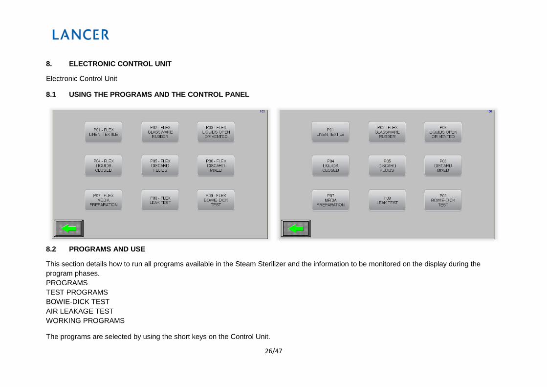
8.1 USING THE PROGRAMS AND THE CONTROL PANEL
8.2 PROGRAMS AND USE
This section details how to run all programs available in the Steam Sterilizer and the information to be monitored on the display during the program phases. PROGRAMS TEST PROGRAMS BOWIE-DICK TEST AIR LEAKAGE TEST WORKING PROGRAMS
The programs are selected by using the short keys on the Control Unit.

27/47
8.3 PLC CONTROL
UNIT & TOUCH SCREEN DISPLAY
Sterilizer has touch screen display; main screen is as in the following.
28/47
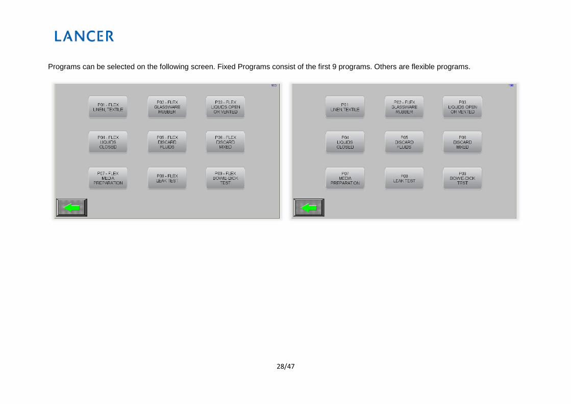
Programs can be selected on the following screen. Fixed Programs consist of the first 9 programs. Others are flexible programs.
29/47
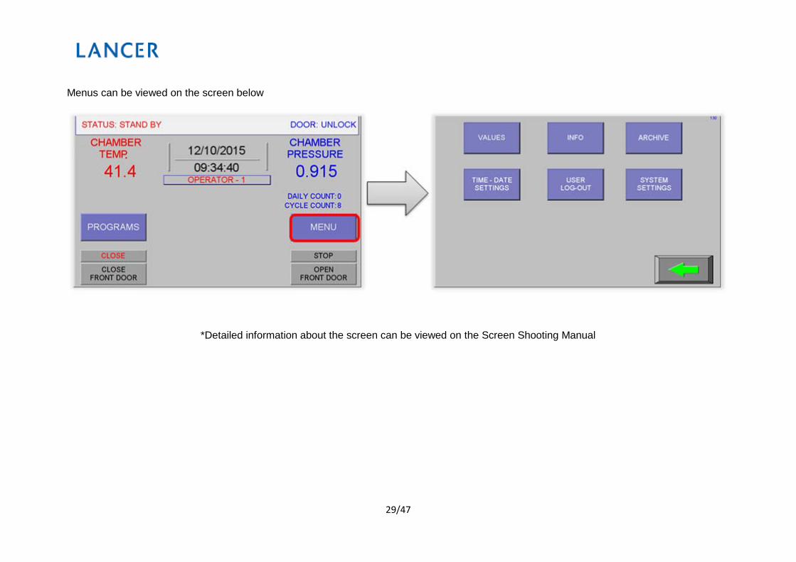
Menus can be viewed on the screen below
*Detailed information about the screen can be viewed on the Screen Shooting Manual

30/47
8.4 SELECTION OF PROGRAMS
Programs can be listed as in the following:
• Linen, textile
• Laboratory Glassware, Rubber
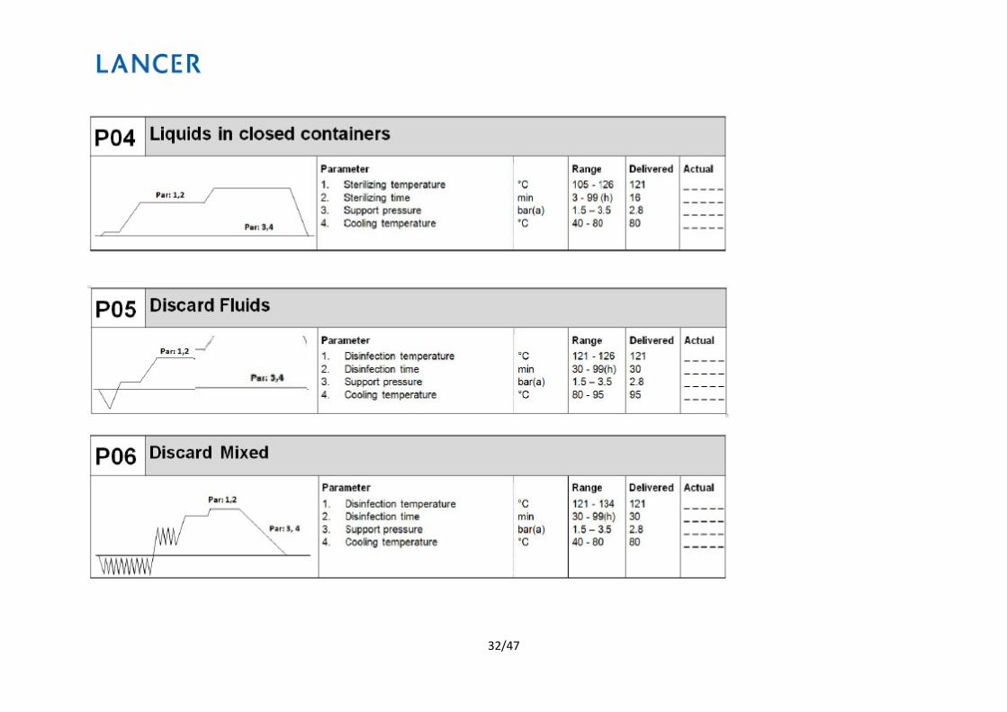
• Liquids in Open or Vented Containers
• Liquids in Closed Containers
• Discard of Fluids
• Discard of Mixed Goods
• Media Preparation
• Automatic Leak Rate Test
• Bowie & Dick Test (Optional)
31/47
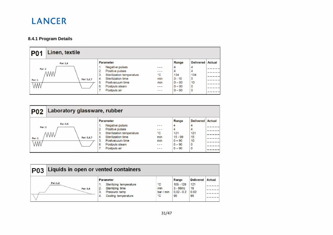
8.4.1 Program Details
32/47

33/47

34/47
8.5 RUNNING A PROGRAM
Acknowledge button should be pressed again after selecting a program to run the selected program. Program will be run after pressing Acknowledge button.
The control unit automatically performs all controls and commands of the system after the selected program is run.
The following prerequisites should be fulfilled in order to run the selected program. Control Unit will not run the program unless such prerequisites are fulfilled, and the following display will be waiting until all conditions are fulfilled to make the generator ready.
The conditions to be fulfilled for the program to run are as follows:
• Readiness of Generator (reaching to proper steam level and pressure)
• Readiness of jacket (reaching to proper steam level and pressure)
• The front door and rear door, if any, are closed (The door(s) of Trans Steam Sterilizer can be closed and opened by pressing the appropriate buttons located on the front panel) If the doors have not been closed by the user, the Control Unit will automatically close both doors, and check if the doors are tightly closed.
• Readiness of gasket (Control Unit, after closing the door(s), will ensure the gasket to be closed automatically)
• Mechanical lock of the door is engaged (Control Unit will ensure the mechanical lock(s) of the door(s) to be closed automatically, and check if the lock(s) is/are engaged)
System Alarms
• Alarm is given, warning is on display and is written on printout paper until the generator, chamber, jacket safety valves give alarm
• If the resistances are very hot, then the alarm is given
• If vacuum motor is not working properly, then there is a vacuum failure.

35/47
• If pressure and temperature are not in sterilization phase of the sterilizer and written on printout paper.
• If there is no water or the water is cut in any time, then vacuum motor does not work, this condition is controlled by water campini in installation
• If there is no air in the system, then alarm is given on the display until air is made available.
• If electricity is cut off, phase of the motor turns
• If there is any defect in temperature sensor or pressure sensor, sterilizer gives alarm.
• If door is not working properly.
8.6 PANEL PRINTER
The following can be monitored in form of hard copy by means of a panel printer used in Steam Sterilizer.
• Starting date of sterilization.
• Total number of sterilization cycles.
• Number and name of selected program.
• Details of selected program (Temperature, Sterilization Time, Drying time, etc.)
• Detailing each sterilization phase separately and the temperature, pressure and time data for that phase.
• Error messages.
• Total sterilization time.

36/47
8.7 REPLACING THE PRINTER PAPER

37/47
9. INTERLOCK SYSTEM
The interlock system is designed to block/allow the operation of steam and air to chamber valves as well as movement of the door by means of a mechanic lock, depending on whether appropriate conditions are present.
The system comprises a supervisor with an independent load temperature sensor and independent chamber pressure sensor mounted on it, an emergency stop, a door limit sensor, and a gasket pressure sensor.
The PLC is in continuous communication with the supervisor. A message alert is issued in the event of communication breakdown or failure of the sensors connected to the supervisor. The process is aborted if such breakdown or failure should occur during operation.
The interlock system is divided into two parts.
9.1 Media Interlock

38/47
The system comprises components which mechanically prevent the opening of steam and air to chamber valves unless appropriate conditions are given. To operate the valves, the door must be close, the emergency stop button must be not pressed, and there must be air pressure in the gasket. Otherwise, the valves will not step in.
9.2. Door Interlock

39/47
The interlock system collects the signals received from the emergency stop and the gasket pressure sensor along with the signals coming from the supervisor, and allows the opening of the door only if appropriate conditions are met. Otherwise, the opening of the door will be blocked by means of a mechanic lock.
Lab Programs:
The supervisor locks the door upon “set” signal received from PLC. The door is locked by closing the relay outlet connected to the PLC. Thereby, the locking mechanism will be activated automatically in case of a PLC failure. After that, the opening of the door is firmly blocked by means of the mechanic lock. By sending a set signal, the “process end temperature” according to the chosen program is sent to the supervisor by PLC. To start the sterilization process, it is required that a confirmation is sent to PLC by the supervisor confirming the receipt of “set” command, and that this confirmation is received by PLC. Thereby, security is provided against any connection or communication error. PLC will not start the process unless a “set” approval signal is received from the supervisor.
After having received a “reset” signal from PLC, the supervisor will compare the “process end temperature” received from the PLC at the beginning of process with the actual load temperature. The PLC will carry out the reset process only if load temperature is below the process end temperature and chamber pressure is within the range of atmospheric pressure +/- 40mb. The interlock system will deactivate the mechanic lock to allow the opening of the door, after having assessed the data received from the supervisor system and other sensors.
Standard Programs:
The interlock system collects the signals received from the emergency stop and the gasket pressure sensor along with the signals coming from the supervisor, and allows the opening of the door only if appropriate conditions are met. Otherwise, the opening of the door will be blocked by means of a mechanic lock.
As distinct from the logic adopted for the liquids program, the supervisor will check only the chamber pressure after having received a reset signal from the PLC in order to reset the system. The PLC will carry out the reset process if chamber pressure is within the range of atmospheric pressure +/- 40mb. In standard programs, load temperature is not controlled for resetting.

40/47
General Properties,
• Every time a “door open” command is received, the PLC will wait for a “reset” signal from the supervisor before opening the door. The door will not open in case of disconnection or communication errors.
• In Lab programs, the process will end only after load temperature has reached safe levels. Load temperature is checked by the PLC both by means of the load sensor mounted on it and the load sensor connected to the supervisor; and the process will end only if both load temperature data are at safe level.
• The PLC will send to the supervisor a “reset” signal only at process end. In case of an error during the process, the supervisor will stay in “set” position. If this is the case, it will not be possible for the PLC to reset the supervisor, but approval of the technician will be required.
• There is continuous communication between the supervisor and PLC. Once this communication is interrupted, the “door open” command will not be processed by the PLC, and the supervisor will automatically shift to “set” position. Approval of the technician will be required for reset.
• There is continuous communication between the supervisor and PLC, while the data coming from the supervisor are continuously monitored by the PLC. The PLC will issue an alert in case of situations like sensor error, cable breaking, and supervisor PLC failure etc. The process is aborted if these should occur during operation. The PLC will not open the doors in any circumstance until the error is recovered.
• The supervisor will automatically shift to “set” position in case of situations like sensor disconnection, sensor failure etc. Approval of the technician will be required for reset.
• For permanent reset subject to approval of the technician, load temperature and chamber pressure must be within the range of atmospheric +/- 40mb. In any other case, only temporary rest can be made by the technician (key reset).

41/47
Diagram of Door Interlock System

42/47
10. MAINTENANCE
10.1 ROUTINE MAINTENANCE
Just like all electrical units, this sterilizer must be used correctly, serviced and checked at regular intervals. These precautions will ensure the sterilizer to work continuously, safely and effectively.
-To prevent operator hazards, the sterilizer must be checked on a regular basis and serviced by the technical assistance service.
-To maintain the sterilizer in good working order, periodically clean all the external parts using a soft damp cloth and normal, neutral detergent (do not use corrosive or abrasive products)
-Do not use abrasive clothes, pads or metal brushes (or anything abrasive) to clean the metal.
-Before starting each cycle, use the lubricating spray over the door seal.
-The formation of white stains on the base of the chamber shows that the demineralised water used is of poor quality
Safety Valves
• Only perform this action when the unit is cold
• Access the three safety valves connected to the device at the chamber, jacket and generator
• Turn the plug located at the upper part of the safety valve anti-clockwise until it reaches to the end of the thread and turns loose
• Return the plug to its original position, screw back on and repeat the operation from the beginning at least a couple of times
10.2. PERIODIC MAINTENANCE Daily Maintenance
• Clean the door seal
• General cleaning of the outer surface

43/47
• General cleaning of the internal surface
Never use hard metallic wire brushes that may damage, scratch or cause rusting of stainless surfaces.
Weekly Maintenance
• Cleaning of the sterilizer chamber
• Cleaning of the trays and the transfer trolley
• Cleaning of the external surfaces
Make sure that the sterilizer is in off position when cleaning the inner area of the sterilizer chamber. Always wear protective gloves to protect your skin as the chamber surface will be hot.
3 Monthly Maintenance
• Clean the strainers in the generator and chamber steam installations every three months. You can carry out such cleaning by removing the cap of the waste trap and subjecting the stainless metallic filter in it to tap water.
Metallic Filter
44/47
The strainers are hot as they are located on the hot steam installations. Wear protective gloves during cleaning.
6. Monthly Maintenance
• Replace the air filter located at the air inlet of the chamber every six months. The Kylcd is programmed to warn the user every sixmonths for replacement of that air filter.
2 Years Maintenance
• Replacement of the door seal.
10 Years Maintenance
• Structural control of the sterilization chamber
10.3. EXTRAORDINARY MAINTENANCE
The extraordinary maintenance is the maintenance which is not mentioned in this Operating Manual. In case such an event occurs, please contact the manufacturer.
The extraordinary maintenance may only be carried out by qualified personnel.
10.4. CLEANING
The extraordinary maintenance may only be carried out by qualified personnel.
Cleaning of External Surfaces

45/47
To maintain the unit in good working order, periodically clean all the external parts using a soft damp cloth and normal, neutral detergent or simply with water (do not use abrasive products)
Do not wash the unit with direct spray or high-pressured jets of water, since any infiltration into the electrical components may damage the operation of the machine and the safety systems
Cleaning the Sterilization Chamber and Accessories
Clean the sterilizer chamber after removing the instruments and accessories, using a non-abrasive damp cloth. To dampen the cloth, use only exclusively distilled or demineralised water. Follow the same procedure for cleaning the transfer trolley and accessories.
Cleaning the sterilization chamber is important for eliminating deposits that could compromise the good working condition of the machine
10.5. RUSTING
The sterilizer is made of materials that never allow rusting of the items to be sterilized. The only reason for any rust inside the sterilizer or on the sterilized items is the instruments in the sterilizer that rust or are likely to cause rusting.
Rusted items placed in the sterilizer will cause the sterilizer to rust over time.
If rusting is observed inside the sterilizer, wipe the inner wall of the sterilizer and clean it by using protective agents suitable for stainless steel.
Never use metallic sponge or brushes for cleaning the sterilizer. Remove the waste residues using a wet soft cloth.
46/47
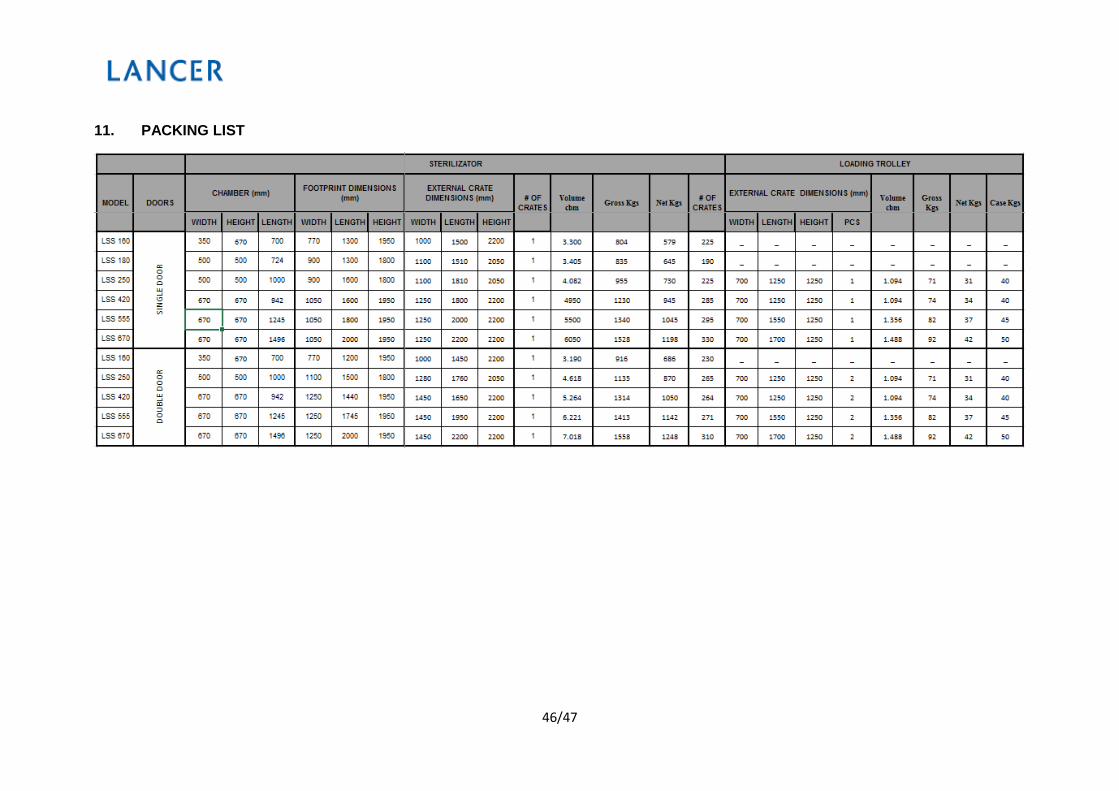
11. PACKING LIST

47/47
12. MAXIMUM LOADING CAPACITY