Embed Size (px)
Citation preview
OPERATOR MANUALThe KRONE Trailer Axle
CONTENTS
General instructions 3
General safety regulations 4
Intended use 4
Requirements imposed on personnel 4
Operating instructions 5
Warranty conditions 6
Scope of the warranty 6
Liability exclusions 6
Warranty period 7
Assertion of warranty claims 8
Approximate times for warranty tasks 9
Markings 12
Axle identification 12
Components of the axle 13
Air suspension 14
Assembly 15
Twinlift 16
Inspection and maintenance guidelines 18
Symbols 18
General instructions 18
Axle 19
Air suspension 22
Air bag spring unit 23
Axle lift 25
Maintenance instructions 26
General instructions 26
Axle repair 26
Replacing a brake disc 26
Checking a brake disc 29
Replacing the wheel bearing unit 32
Installation - ABS sensor 35
Checking the wheel bearing unit 35
Spare parts data sheets 37
Axle 37
Brake callipers 39
Air suspension 40
Integration 41
Axle lift 42
Tools 43
Testing and warning instructions 44
3
This operator manual provides information concerning the KRONE Trailer Axle In addition to the components used, it also contains information for maintenance and repair of the KRONE Trailer Axle. This manual should provide information for the user, and it should also serve as an information source for trained specialists and authorised specialist companies of the motor vehicle trade.
With regard to the information provided in this manual, we assume no responsibility for its accuracy, content, or actuality. The content and information of this manual constitute neither warranties nor assured characteristics as defined by German law or the German Civil Code (BGB), nor can the content and information of this manual be construed as such.
Claims arising from information, recommendation or consulting cannot be derived from the provision of this manual. Liability for damage is not accepted, except in the case of intent or gross negligence on our part, or unless required by law. The texts and graphics used in this manual are subject to the right of use and exploitation and ownership of Fahrzeugwerk Bernard Krone GmbH, duplication or dissemination in any form require our written consent. The brand names used, even if they are not marked in every case, are nevertheless subject to the regulations of trade mark law.
If disputes of a legal nature should arise from the use of the information in this operator manual, such disputes are subject to German law exclusively. The Rheine District Court is agreed as the place of jurisdiction. If speific clauses of this declaration of the restriction of liability do not or no longer conform to the applicable statutoryregulations, then the validity of the other clauses shall remain hereby unaffected.
Carefully read the information in this manual all the way through and particularly comply with the safety instructions on the following pages. If there are questions that are not answered in this manual, please contact KRONE Customer Service:
Fahrzeugwerk Bernard KRONE GmbHBernard-Krone-Straße 149757 Werlte, GermanyPhone: +49 (0) 5951 209-320Fax: +49 (0) 5951 209-367Email: [email protected]: www.krone-trailer.com
The KRONE Mobility Hotline is available to you outside of office hours:00800 225557663 or +49 (0) 7333 808512
general information
general safety regulations
Intended use
The KRONE Trailer Axle must only be used as intended within the manufacturer specifications prescribed by KRONE and in compliance with mandatory statutory regulations.The owner is responsible for complying with the intended use.
This also includes: compliance with the instructions in this operator’s manual compliance with the maintenance guidelines that apply for all KRONE axles and KRONE assemblies.
These guidelines are a component of our warranty conditions execution of the following maintenance tasks in accordance with the prescribed intervals for compliance
and the full operational readiness, as well as traffic safety and operational safety
The KRONE Trailer Axle can be loaded with a maximum axle load of 9,000 kg. Only mid-centred steel or aluminium rims, size 22.5 inches, with a press-in depth of 120 mm that are approved by KRONE may be used.
To maintain the validity of the operating permit for KRONE axles and assemblies, only use original KRONE spare parts or spare parts from other manufactures that are approved by KRONE. KRONE accepts no liability for installation of unsuitable or non-approved parts in the product. All uses other than the use described under “Intended use” are considered to be non-intended use.
Requirements imposed on personnel
The rectification of determined defects and replacement of worn components must only be executed by aspecialist in qualified workshops or by authorised specialist companies in the motor vehicle trade, that have all the qualifications and the tools necessary for execution of these tasks. Maintenance must only be executed by a specialist in qualified workshops or by authorised specialist companies in the motor vehicle trade, who work in compliance with all generally valid safety regulations. Repair or maintenance by inadequately qualified personnel results in incalculable risks for people, material assets and the environment.
5
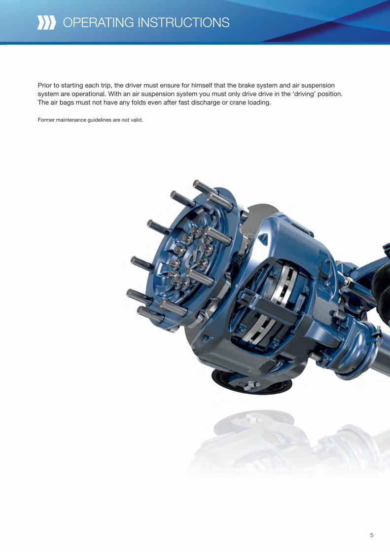
Prior to starting each trip, the driver must ensure for himself that the brake system and air suspension system are operational. With an air suspension system you must only drive drive in the ‘driving’ position. The air bags must not have any folds even after fast discharge or crane loading.
Former maintenance guidelines are not valid.
operating instructions
Warranty conditions
The KRONE Trailer Axle is designed for low maintenance to 6 years. We not only promise you quality, we deliver it to you. A check as part of your annual main inspection is sufficient and we grant you a full 6-year warranty on the bearing and axle body without mileage limit for the KRONE Trailer Axle. The manufacturer (hereinafter KRONE) grants to users of the axle systems and compact bearing axles of the KRONE Trailer Axle manufactured and delivered by KRONE since 01/10/2014, a warranty in accordance with the following con-ditions:
Scope of the warranty
KRONE grants a warranty for product defects that are verifiably attributed to a material or manufacturing fault. The warranty exists in addition to the legal warranty for defects on the part of the seller arising from the purchase contract, with the first end user, and does not affect this legal warranty for defects. The war-ranty period is based on the normal use of the vehicle, which is defined in chapter 3. The warranty covers the costs for replacement of defective parts, as well as the wage costs incurred within the framework of the conditions specified by KRONE. The warranty only applies to faults or defects of the product which are at-tributable to KRONE. Consequential damage, in particular towing costs, rental costs for replacement vehicles, claims for lost profit or damage compensation are excluded from the warranty. A more extensiveliability due to mandatory statutory regulations remains hereby unaffected.
Liability exclusions
Excluded from the warranty is wear to parts such as brake pads or brake discs and damage that occurs through:
improper use of the KRONE axle systems, trailer/braking mis use, mechanical damage due to accidents, collision or other impact, negligent or wilful destruction, as well as fire, misuse of the vehicle
(for example: Overload, overheating, use under abnormal conditions), incorrect maintenance, in particular neglecting the regular inspection and maintenance tasks described
in the current KRONE inspection and maintenance guidelines (see www.krone-trailer.com), conversion of parts or modifications to the KRONE axle systems, or use of parts of a non-KRONE origin
instead of original KRONE spare parts or use of unsuitable lubricants. Also excluded from the warranty are such phenomena, as noises, odours, vibration, oil leaks, that have no influence on the merchantability of the KRONE axle systems. If the defect becomes evident within a period of 6 months after first delivery of the vehicle to the first customer, then the irrefutable assumption is that a material fault or manufacturing fault is involved.
7
Warranty period
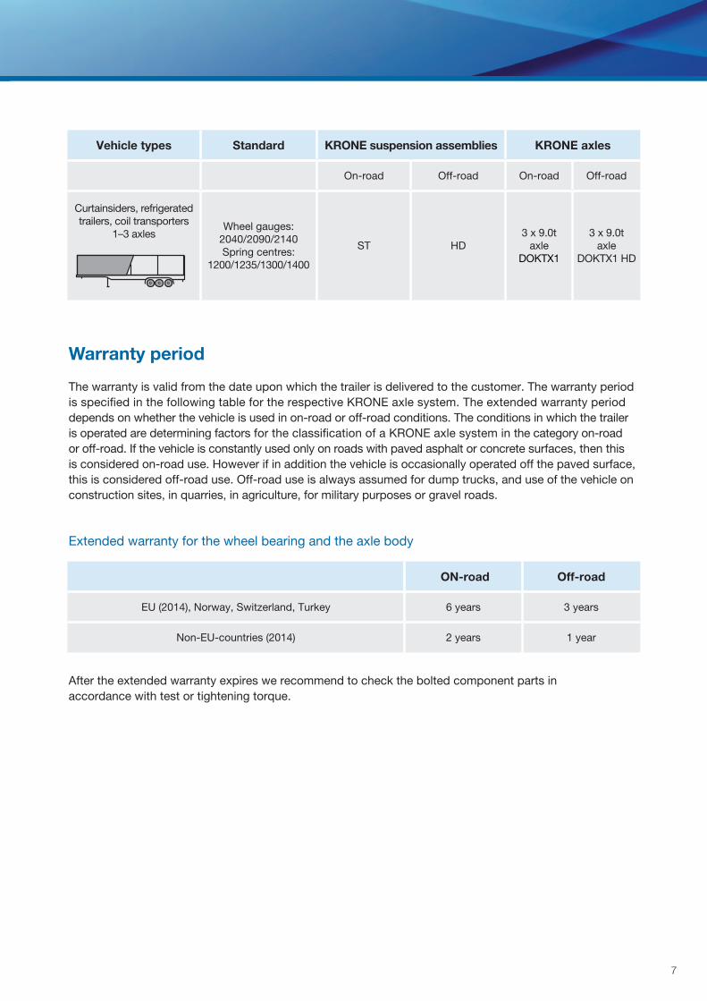
The warranty is valid from the date upon which the trailer is delivered to the customer. The warranty period is specified in the following table for the respective KRONE axle system. The extended warranty period depends on whether the vehicle is used in on-road or off-road conditions. The conditions in which the trailer is operated are determining factors for the classification of a KRONE axle system in the category on-road or off-road. If the vehicle is constantly used only on roads with paved asphalt or concrete surfaces, then this is considered on-road use. However if in addition the vehicle is occasionally operated off the paved surface, this is considered off-road use. Off-road use is always assumed for dump trucks, and use of the vehicle on construction sites, in quarries, in agriculture, for military purposes or gravel roads.
Extended warranty for the wheel bearing and the axle body
After the extended warranty expires we recommend to check the bolted component parts in accordance with test or tightening torque.
Vehicle types Standard KRONE suspension assemblies KRONE axles
On-road Off-road On-road Off-road
Curtainsiders, refrigerated trailers, coil transporters
1–3 axlesWheel gauges:
2040/2090/2140Spring centres:
1200/1235/1300/1400
ST HD3 x 9.0t
axleDOKTX1
3 x 9.0taxle
DOKTX1 HD
ON-road Off-road
EU (2014), Norway, Switzerland, Turkey 6 years 3 years
Non-EU-countries (2014) 2 years 1 year
Warranty conditions
* KRONE reserves the right to request the original documents!
24 months
Components: Air spring bracket, trailing arms, brake cylinders, brake callipers without pads, axle lift, air spring bellows, ABS sensor and flywheel, brake shoes (without pads), spring shackle, shock absorbers
24 months, however wear is excluded as a reason for complaint
Components: Brake discs, brake pads, seals, silent block
For determination of the precise mileage the data of ABS, EBS, and similar measuring systems are authoritative, if a through these displays a seamless recording of the vehicle’s total mileage is possible. Specification of incorrect mileage or manipulation of the measurement devices invalidates the warranty. A warranty claim does not extend the warranty. Parts replaced as part of warranty claims, are warranted for 6 months, or at least for the running warranty period.
Enforcement of warranty claims
A warranty claim is enforced through the use of a KRONE warranty application submitted to KRONE. The KRONE warranty application must include the information asked for on the application. The KRONE warranty application can be downloaded at the address www.krone-trailer.com.
The following must be provided with the KRONE warranty application: copies of the maintenance verifications* if there are complaints regarding the wheel hub units, the digital EBS/ODR datasets if there are complaints regarding the brake components, the log of brake force/trailer
match and the digital EBS/ODR datasets
A warranty claim must be enforced at KRONE without delay, at the latest 2 weeks after determination of the error. The removed faulty components must be kept safe and must only be disposed of after written consent from KRONE.KRONE is entitled to bill for costs that are incurred due to wrongful warranty claims.
9
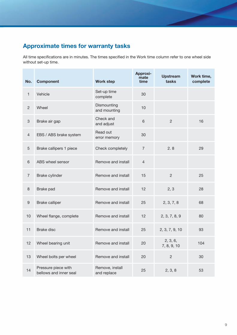
Approximate times for warranty tasks
All time specifications are in minutes. The times specified in the Work time column refer to one wheel side without set-up time.
No. Component Work step
Approxi-matetime
Upstream tasks
Work time, complete
1 VehicleSet-up time complete
30
2 WheelDismounting and mounting
10
3 Brake air gapCheck andand adjust
6 2 16
4 EBS / ABS brake systemRead out error memory
30
5 Brake callipers 1 piece Check completely 7 2. 8 29
6 ABS wheel sensor Remove and install 4
7 Brake cylinder Remove and install 15 2 25
8 Brake pad Remove and install 12 2, 3 28
9 Brake calliper Remove and install 25 2, 3, 7, 8 68
10 Wheel flange, complete Remove and install 12 2, 3, 7, 8, 9 80
11 Brake disc Remove and install 25 2, 3, 7, 9, 10 93
12 Wheel bearing unit Remove and install 202, 3, 6,
7, 8, 9, 10104
13 Wheel bolts per wheel Remove and install 20 2 30
14Pressure piece with bellows and inner seal
Remove, install and replace
25 2, 3, 8 53
Warranty conditions
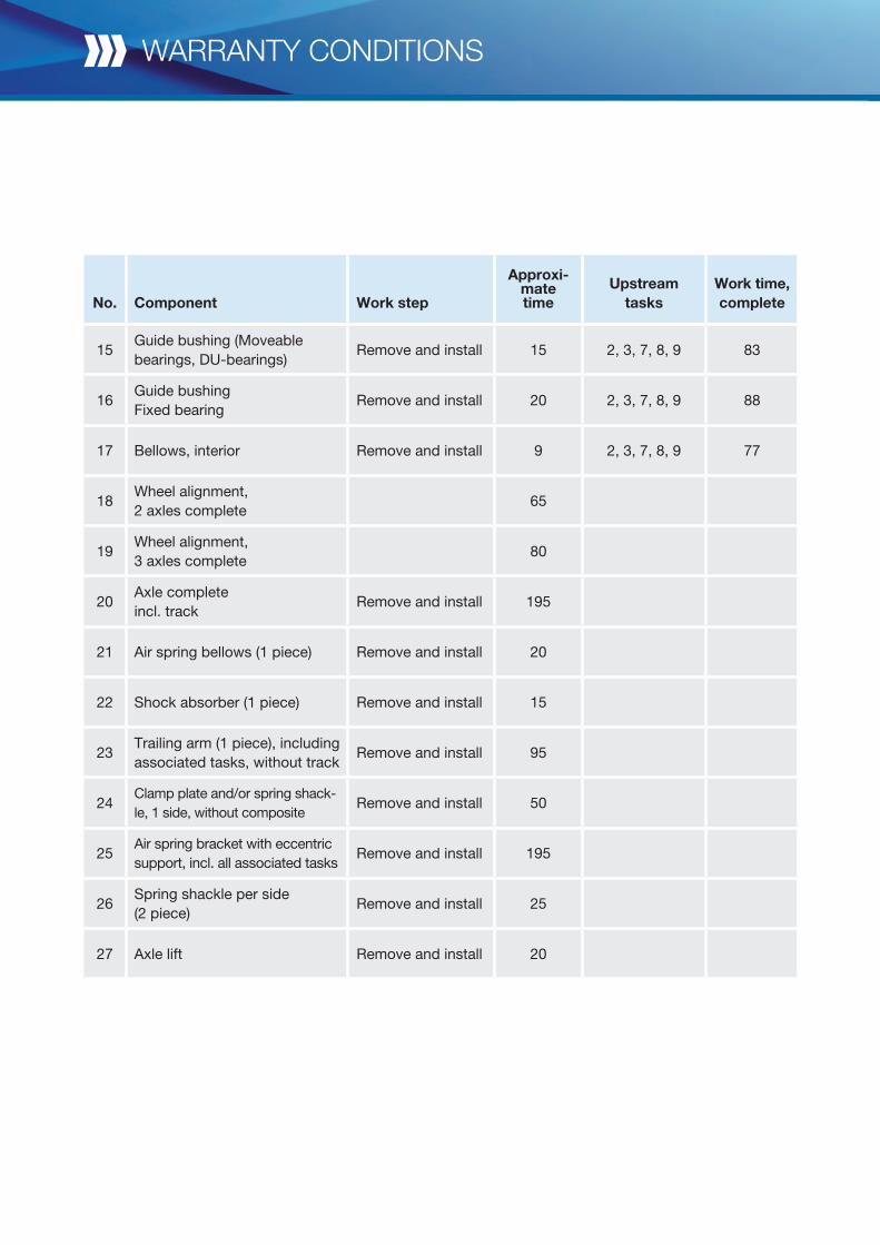
No. Component Work step
Approxi-mate time
Upstream tasks
Work time, complete
15Guide bushing (Moveable bearings, DU-bearings)
Remove and install 15 2, 3, 7, 8, 9 83
16Guide bushing Fixed bearing
Remove and install 20 2, 3, 7, 8, 9 88
17 Bellows, interior Remove and install 9 2, 3, 7, 8, 9 77
18Wheel alignment,2 axles complete
65
19Wheel alignment,3 axles complete
80
20Axle complete incl. track
Remove and install 195
21 Air spring bellows (1 piece) Remove and install 20
22 Shock absorber (1 piece) Remove and install 15
23Trailing arm (1 piece), including associated tasks, without track
Remove and install 95
24Clamp plate and/or spring shack-le, 1 side, without composite
Remove and install 50
25Air spring bracket with eccentric support, incl. all associated tasks
Remove and install 195
26Spring shackle per side(2 piece)
Remove and install 25
27 Axle lift Remove and install 20
11
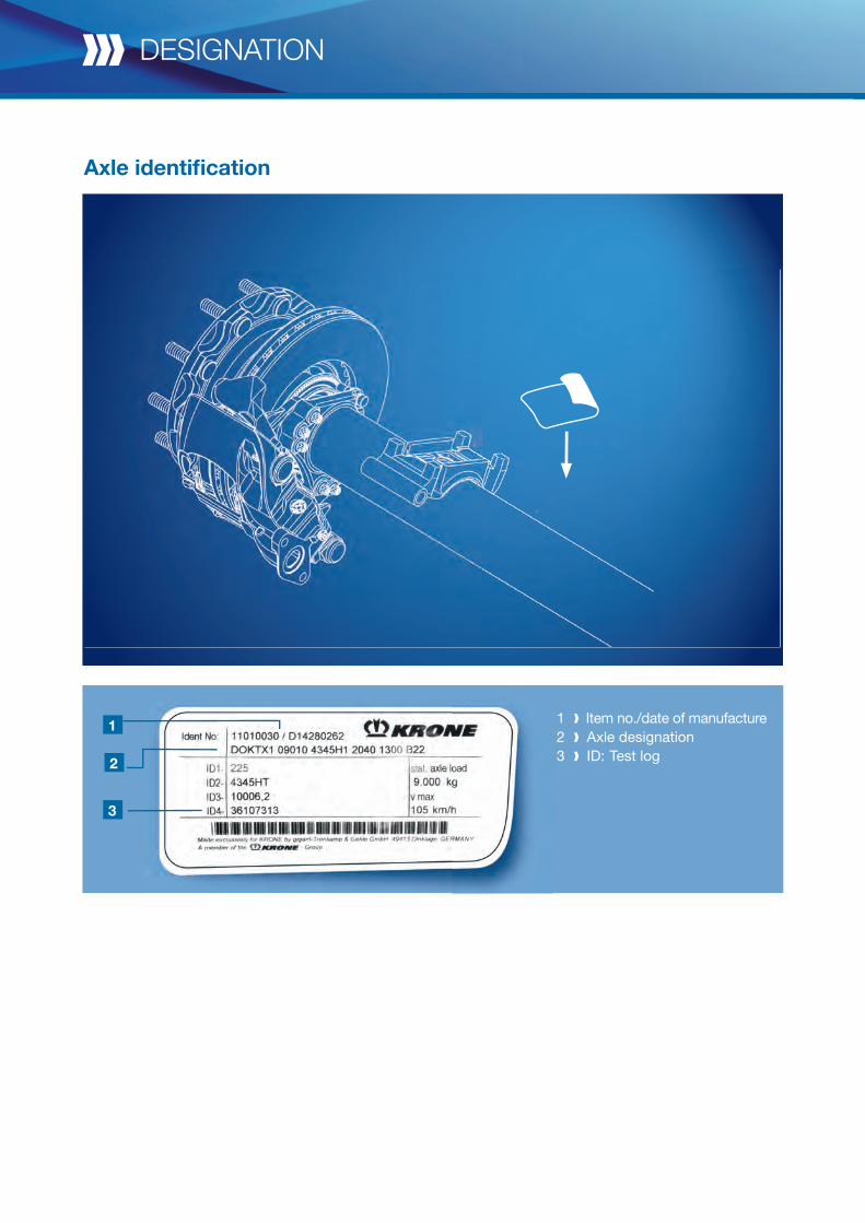
Axle identifi cation
designation
1 Item no./date of manufacture 2 Axle designation 3 ID: Test log
1
3
2
13
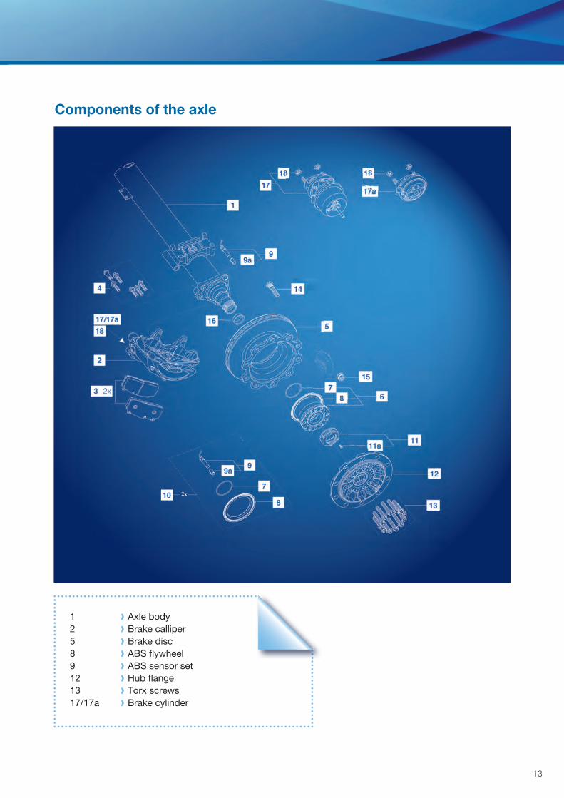
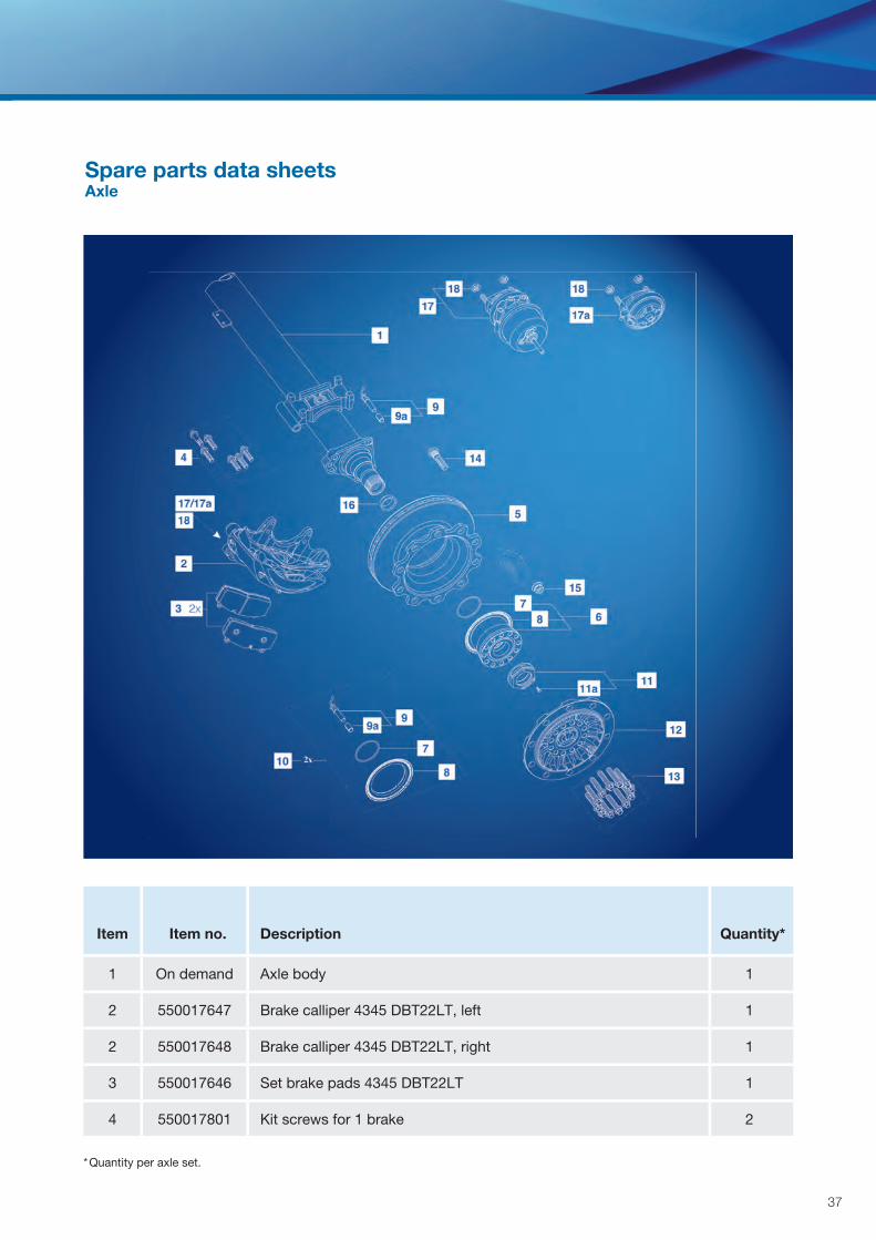
Components of the axle
1 Axle body 2 Brake calliper 5 Brake disc 8 ABS fl ywheel 9 ABS sensor set 12 Hub fl ange 13 Torx screws 17/17a Brake cylinder
13
12
11
6
14
1
4
2
17/17a18
3 2x
9
10 2x
99a
7
8
designation
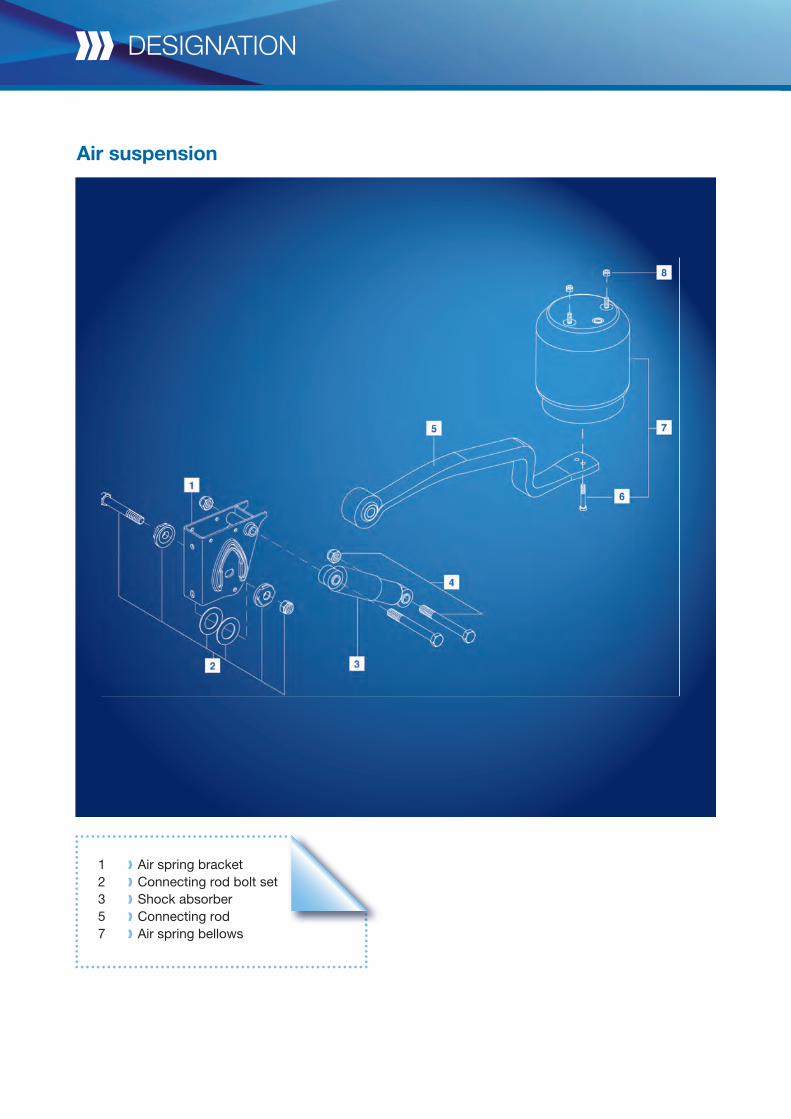
Air suspension
1 Air spring bracket 2 Connecting rod bolt set 3 Shock absorber 5 Connecting rod 7 Air spring bellows
15
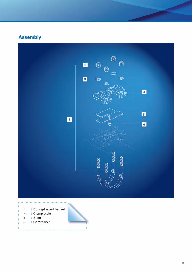
Assembly
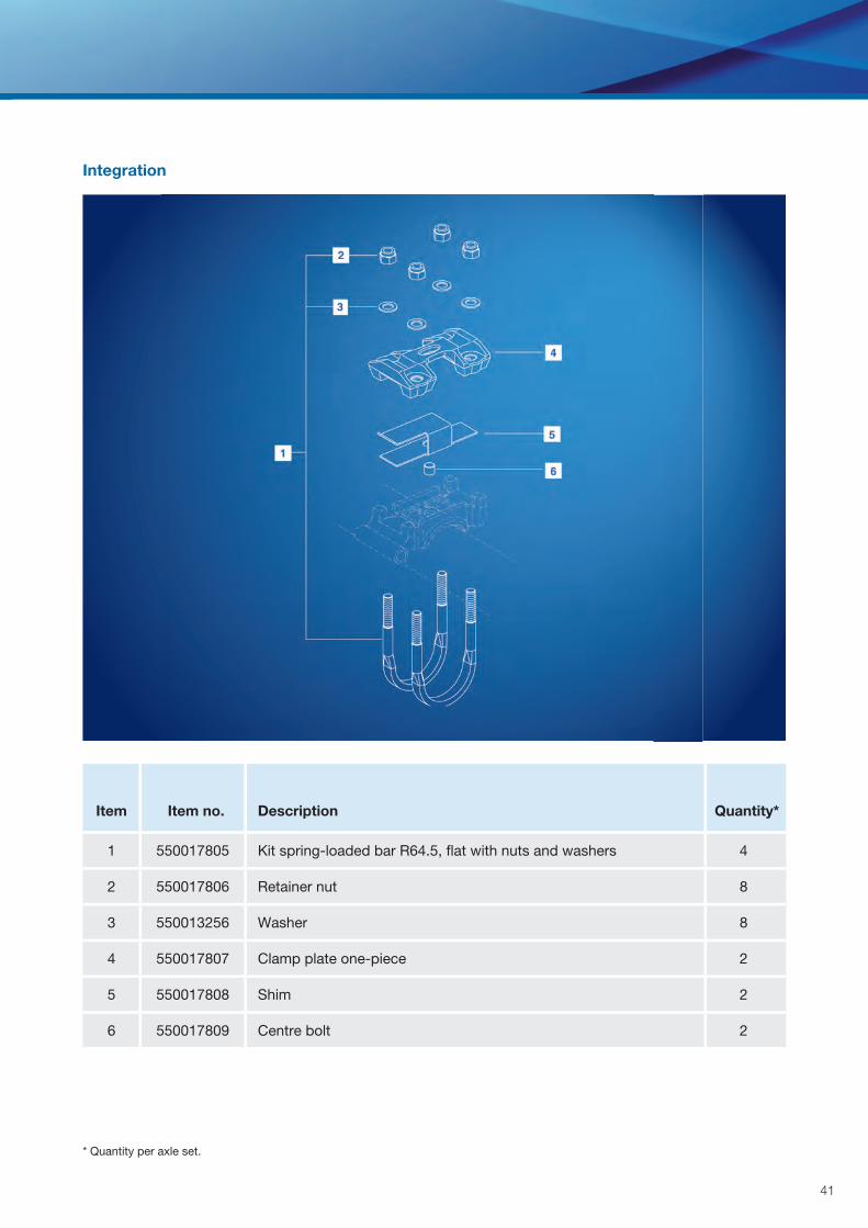
1 Spring-loaded bar set 4 Clamp plate 5 Shim 6 Centre bolt
designation
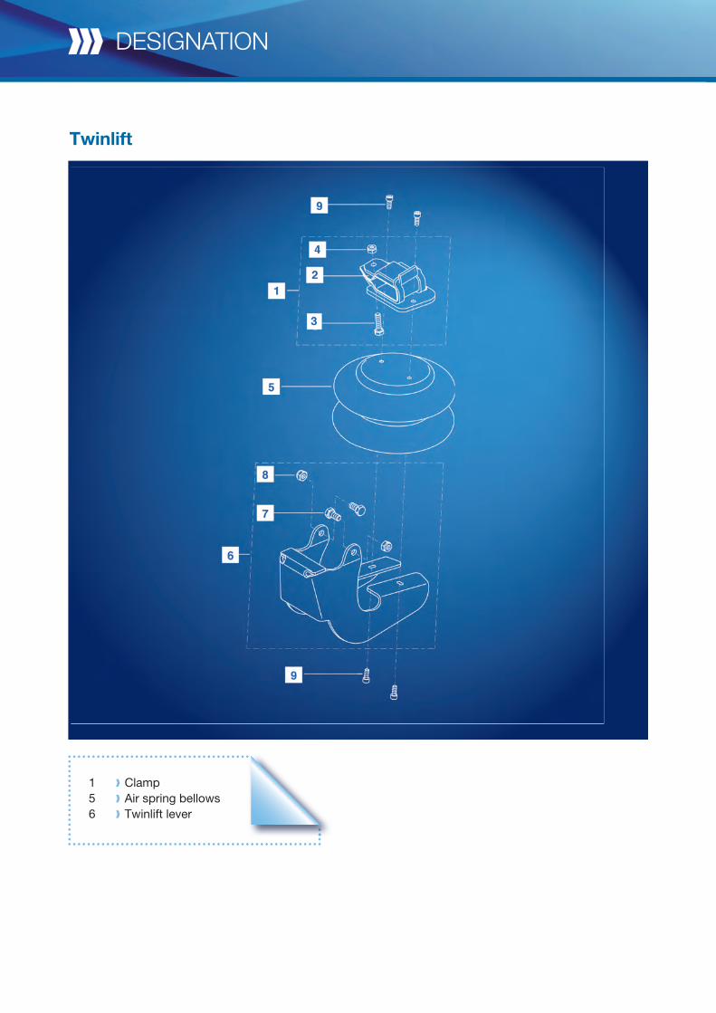
Twinlift
1 Clamp 5 Air spring bellows 6 Twinlift lever
17
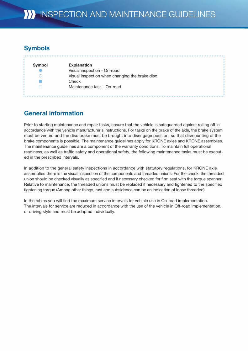
Symbols
General information
Prior to starting maintenance and repair tasks, ensure that the vehicle is safeguarded against rolling off in accordance with the vehicle manufacturer’s instructions. For tasks on the brake of the axle, the brake system must be vented and the disc brake must be brought into disengage position, so that dismounting of the brake components is possible. The maintenance guidelines apply for KRONE axles and KRONE assemblies.The maintenance guidelines are a component of the warranty conditions. To maintain full operationalreadiness, as well as traffic safety and operational safety, the following maintenance tasks must be execut-ed in the prescribed intervals.
In addition to the general safety inspections in accordance with statutory regulations, for KRONE axleassemblies there is the visual inspection of the components and threaded unions. For the check, the threaded union should be checked visually as specified and if necessary checked for firm seat with the torque spanner. Relative to maintenance, the threaded unions must be replaced if necessary and tightened to the specifiedtightening torque (Among other things, rust and subsidence can be an indication of loose threaded).
In the tables you will find the maximum service intervals for vehicle use in On-road implementation. The intervals for service are reduced in accordance with the use of the vehicle in Off-road implementation, or driving style and must be adapted individually.
Symbol Explanation Visual inspection - On-road Visual inspection when changing the brake disc Check Maintenance task - On-road
inspection and maintenance guidelines
19
2
5
3
6
13
15
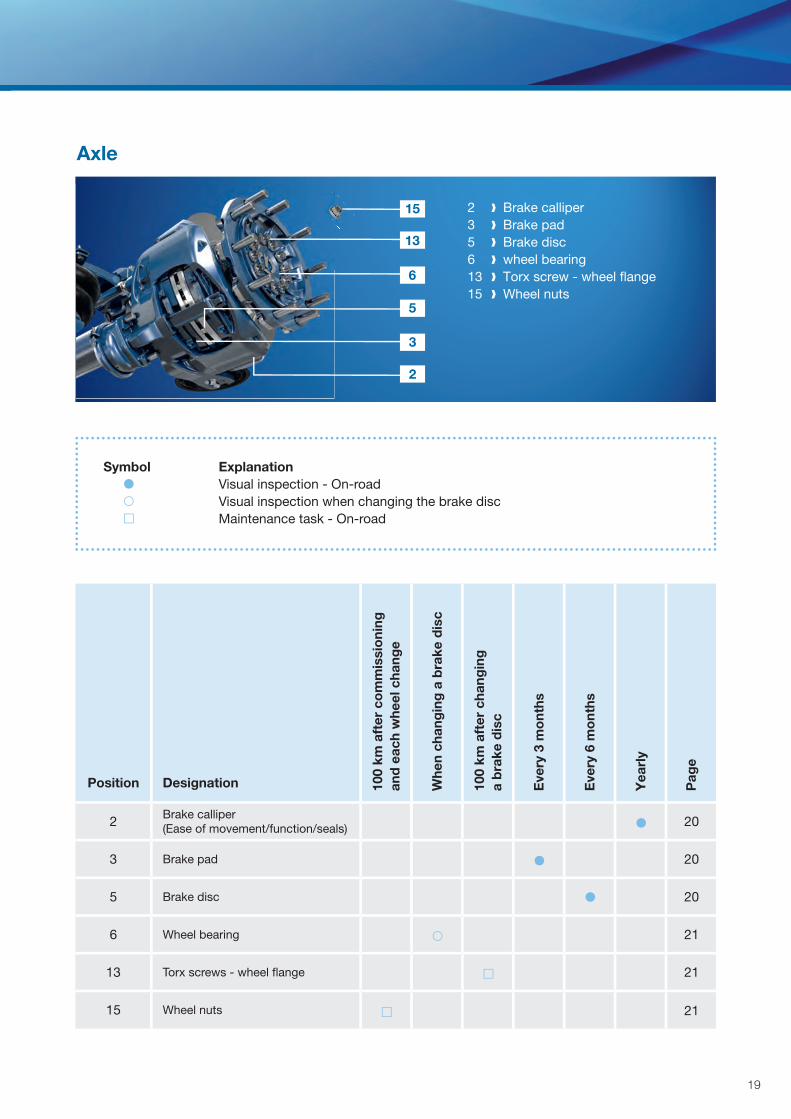
Axle
2 Brake calliper3 Brake pad5 Brake disc6 wheel bearing13 Torx screw - wheel fl ange15 Wheel nuts
Symbol Explanation Visual inspection - On-road Visual inspection when changing the brake disc Maintenance task - On-road
Position Designation 100
km a
fter
co
mm
issi
oni
ngan
d e
ach
whe
el c
hang
e
Whe
n ch
ang
ing
a b
rake
dis
c
100
km a
fter
cha
ngin
ga
bra
ke d
isc
Eve
ry 3
mo
nths
Eve
ry 6
mo
nths
Yea
rly
Pag
e
2 Brake calliper(Ease of movement/function/seals) 20
3 Brake pad 20
5 Brake disc 20
6 Wheel bearing 21
13 Torx screws - wheel fl ange 21
15 Wheel nuts 21
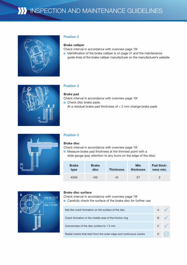
Position 2 Brake calliperCheck interval in accordance with overview page 19!
Identification of the brake calliper is on page 31 and the maintenance guide-lines of the brake calliper manufacturer on the manufacturer’s website
Position 3
Brake padCheck interval in accordance with overview page 19!
Check disc brake pads. At a residual brake pad thickness of < 2 mm change brake pads
Position 5
Brake discCheck interval in accordance with overview page 19!
Measure brake pad thickness at the thinnest point with a slide gauge (pay attention to any burrs on the edge of the disc)
Brake disc surfaceCheck interval in accordance with overview page 19!
Carefully check the surface of the brake disc for further use
inspection and maintenance guidelines
Net-like crack formation on the surface of the disc A üCrack formation in the middle area of the friction ring B üUnevenness of the disc surface to 1.5 mm C üRadial cracks that start from the outer edge and continuous cracks D y
Braketype
Brakedisc Thickness
Min thickness
Pad thick-ness min.
4345 430 45 37 2
21
Position 6
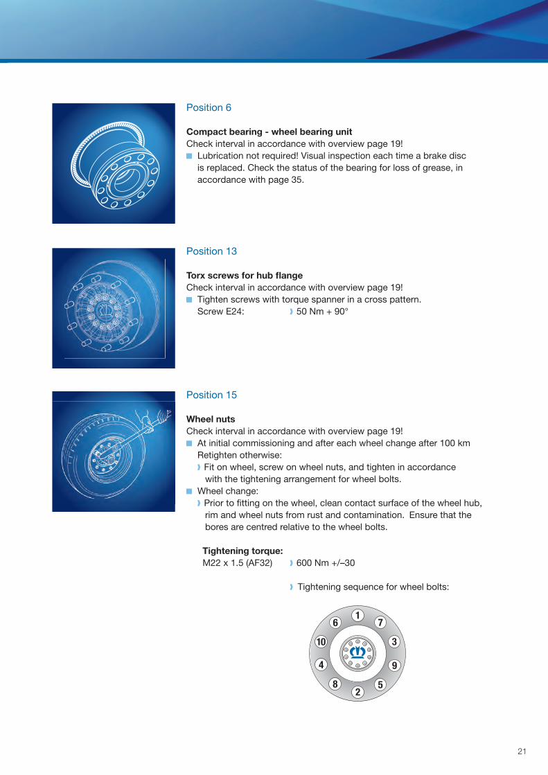
Compact bearing - wheel bearing unitCheck interval in accordance with overview page 19!
Lubrication not required! Visual inspection each time a brake disc is replaced. Check the status of the bearing for loss of grease, in accordance with page 35.
Position 13
Torx screws for hub fl angeCheck interval in accordance with overview page 19!
Tighten screws with torque spanner in a cross pattern. Screw E24: 50 Nm + 90°
Position 15
Wheel nutsCheck interval in accordance with overview page 19!
At initial commissioning and after each wheel change after 100 km Retighten otherwise: Fit on wheel, screw on wheel nuts, and tighten in accordance with the tightening arrangement for wheel bolts.
Wheel change: Prior to fi tting on the wheel, clean contact surface of the wheel hub, rim and wheel nuts from rust and contamination. Ensure that the bores are centred relative to the wheel bolts.
Tightening torque: M22 x 1.5 (AF32) 600 Nm +/–30
Tightening sequence for wheel bolts:
5
4
1
2
3
6
8
9
10
7
inspection and maintenance guidelines
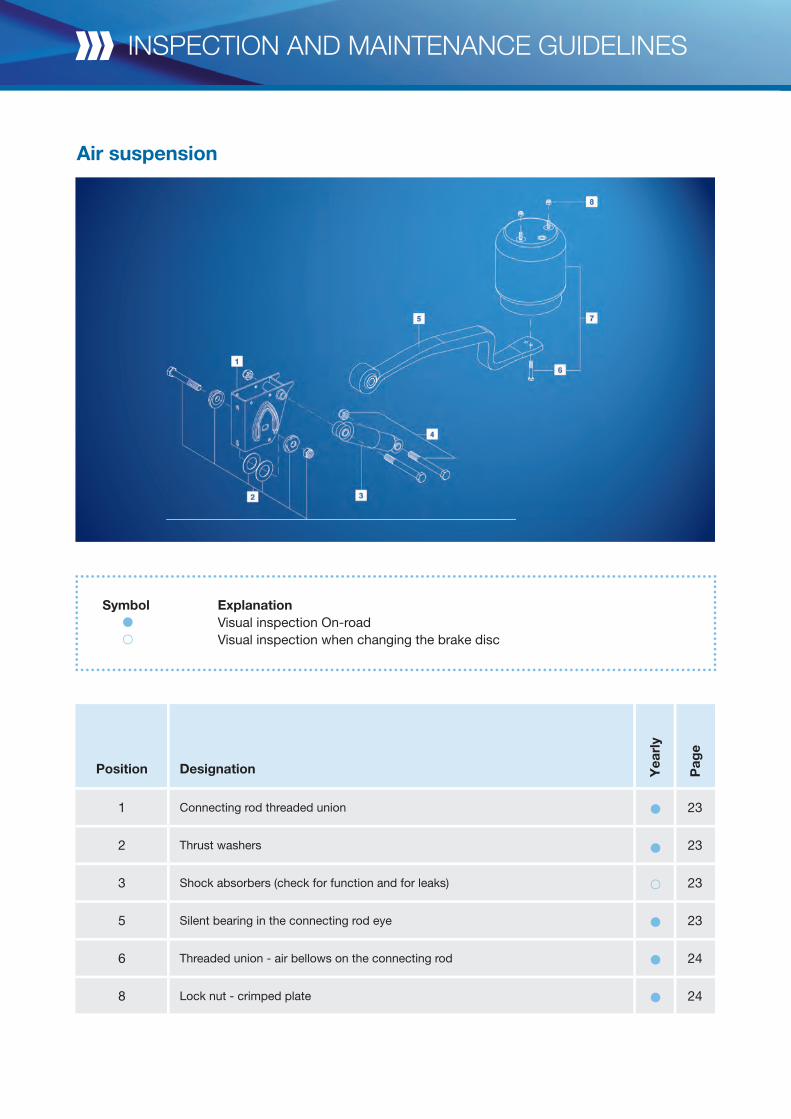
Air suspension
jähr
lich
Sei
te
Position Designation Yea
rly
Pag
e
1 Connecting rod threaded union 23
2 Thrust washers 23
3 Shock absorbers (check for function and for leaks) 23
5 Silent bearing in the connecting rod eye 23
6 Threaded union - air bellows on the connecting rod 24
8 Lock nut - crimped plate 24
Symbol Explanation Visual inspection On-road Visual inspection when changing the brake disc
23
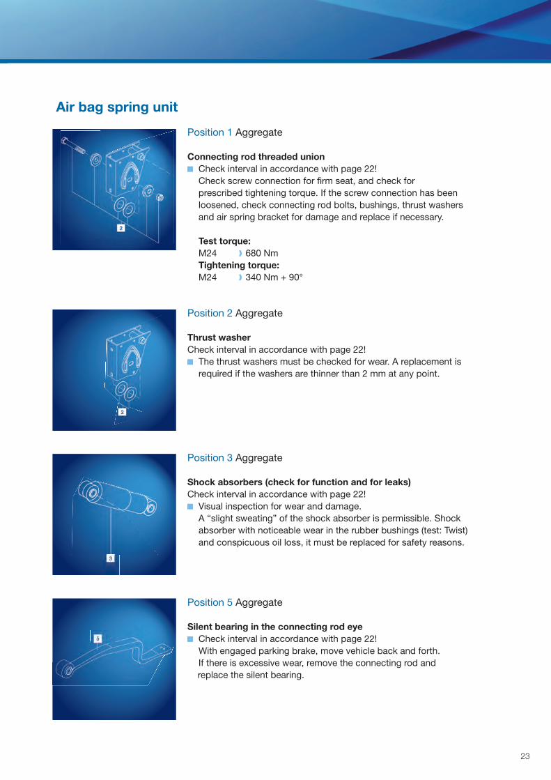
Position 1 Aggregate
Connecting rod threaded union Check interval in accordance with page 22!
Check screw connection for firm seat, and check for prescribed tightening torque. If the screw connection has been loosened, check connecting rod bolts, bushings, thrust washers and air spring bracket for damage and replace if necessary.
Test torque: M24 680 Nm Tightening torque: M24 340 Nm + 90°
Position 2 Aggregate
Thrust washerCheck interval in accordance with page 22!
The thrust washers must be checked for wear. A replacement is required if the washers are thinner than 2 mm at any point.
Position 3 Aggregate
Shock absorbers (check for function and for leaks)Check interval in accordance with page 22! Visual inspection for wear and damage.
A “slight sweating” of the shock absorber is permissible. Shock absorber with noticeable wear in the rubber bushings (test: Twist) and conspicuous oil loss, it must be replaced for safety reasons.
Position 5 Aggregate
Silent bearing in the connecting rod eye Check interval in accordance with page 22!
With engaged parking brake, move vehicle back and forth. If there is excessive wear, remove the connecting rod and replace the silent bearing.
Air bag spring unit
inspection and maintenance guidelines
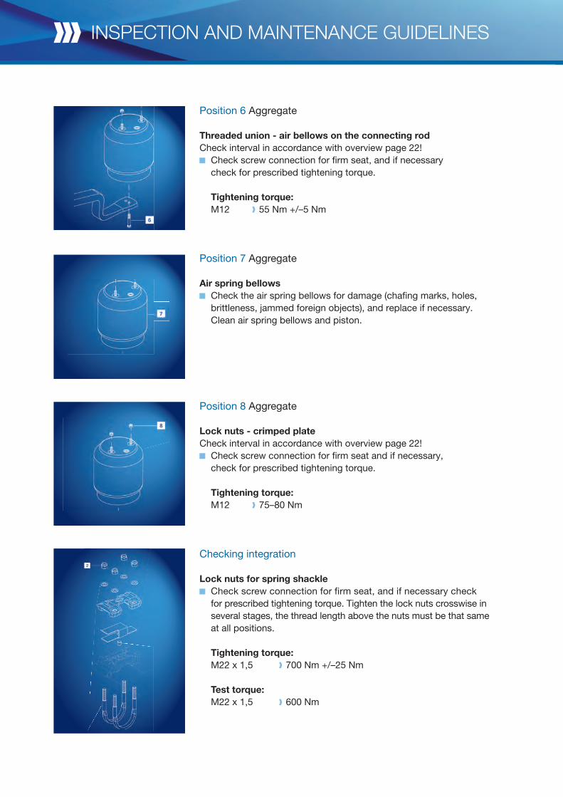
Position 6 Aggregate
Threaded union - air bellows on the connecting rodCheck interval in accordance with overview page 22!
Check screw connection for fi rm seat, and if necessary check for prescribed tightening torque.
Tightening torque: M12 55 Nm +/–5 Nm
Position 7 Aggregate
Air spring bellows Check the air spring bellows for damage (chafi ng marks, holes,
brittleness, jammed foreign objects), and replace if necessary. Clean air spring bellows and piston.
Position 8 Aggregate
Lock nuts - crimped plateCheck interval in accordance with overview page 22!
Check screw connection for fi rm seat and if necessary, check for prescribed tightening torque.
Tightening torque: M12 75–80 Nm
Checking integration
Lock nuts for spring shackle Check screw connection for firm seat, and if necessary check
for prescribed tightening torque. Tighten the lock nuts crosswise in several stages, the thread length above the nuts must be that same at all positions.
Tightening torque: M22 x 1,5 700 Nm +/–25 Nm
Test torque: M22 x 1,5 600 Nm
25
Axle lift
Position Designation Yea
rly
Pag
e
3, 4, 7, 8, 9 Threaded union 25
Symbol Explanation Visual inspection On-road
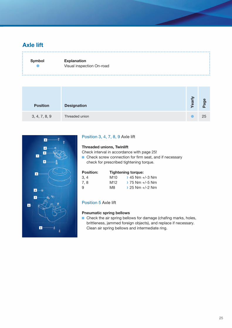
Position 3, 4, 7, 8, 9 Axle lift
Threaded unions, TwinliftCheck interval in accordance with page 25!
Check screw connection for firm seat, and if necessary check for prescribed tightening torque.
Position: Tightening torque: 3, 4 M10 45 Nm +/-3 Nm7, 8 M12 75 Nm +/-5 Nm9 M8 25 Nm +/-2 Nm
Position 5 Axle lift
Pneumatic spring bellows Check the air spring bellows for damage (chafi ng marks, holes,
brittleness, jammed foreign objects), and replace if necessary. Clean air spring bellows and intermediate ring.
!
General information
To maintain the validity of the operating permit for KRONE axles and assemblies, only use original KRONE spare parts or spare parts from other manufactures that are approved by KRONE. The rectification of determined defects and replacement of worn components must only be executed by a specialised workshop. Maintenance and repair must only be executed by qualified specialists who work in compliance with generally valid safety regulations. Prior to starting maintenance and repair tasks, ensure that the vehicle is properly safeguarded against rolling off. For tasks on the brakes of the axle, the brake system must be vented, to bring the disc brake into disengage position, so that the dismounting of the brake components is possible.
Axle repair
Replacing a brake disc
Dismount wheel flange and brake disc.
Caution Prior to starting the repair tasks the vehicle must be safeguarded against rolling off! The service brake and parking brake must be in disengaged and secured position!
Dismount the wheel.
Reset the brake and remove the brake pad, in accordance with the guidelines specified by the manufacturer of the brake calliper.
If the disc brake has a parking brake function, it must be ensured that the spring-load accumulator is completely released and is mechanically secured in this position.
maintenance instructions
!
27
!
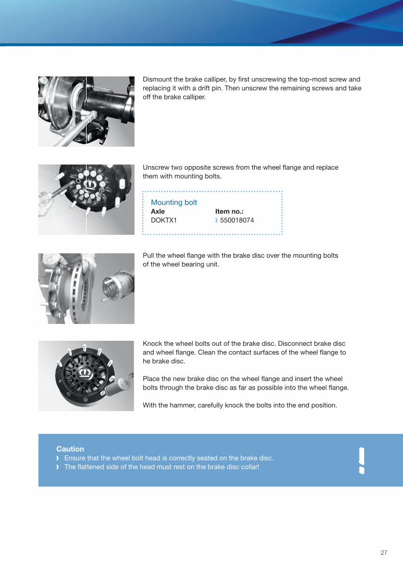
Dismount the brake calliper, by first unscrewing the top-most screw and replacing it with a drift pin. Then unscrew the remaining screws and take off the brake calliper.
Unscrew two opposite screws from the wheel flange and replace them with mounting bolts.
Mounting bolt Axle Item no.: DOKTX1 550018074
Pull the wheel flange with the brake disc over the mounting bolts of the wheel bearing unit.
Knock the wheel bolts out of the brake disc. Disconnect brake disc and wheel flange. Clean the contact surfaces of the wheel flange to he brake disc.
Place the new brake disc on the wheel flange and insert the wheel bolts through the brake disc as far as possible into the wheel flange.
With the hammer, carefully knock the bolts into the end position.
Caution Ensure that the wheel bolt head is correctly seated on the brake disc. The flattened side of the head must rest on the brake disc collar!
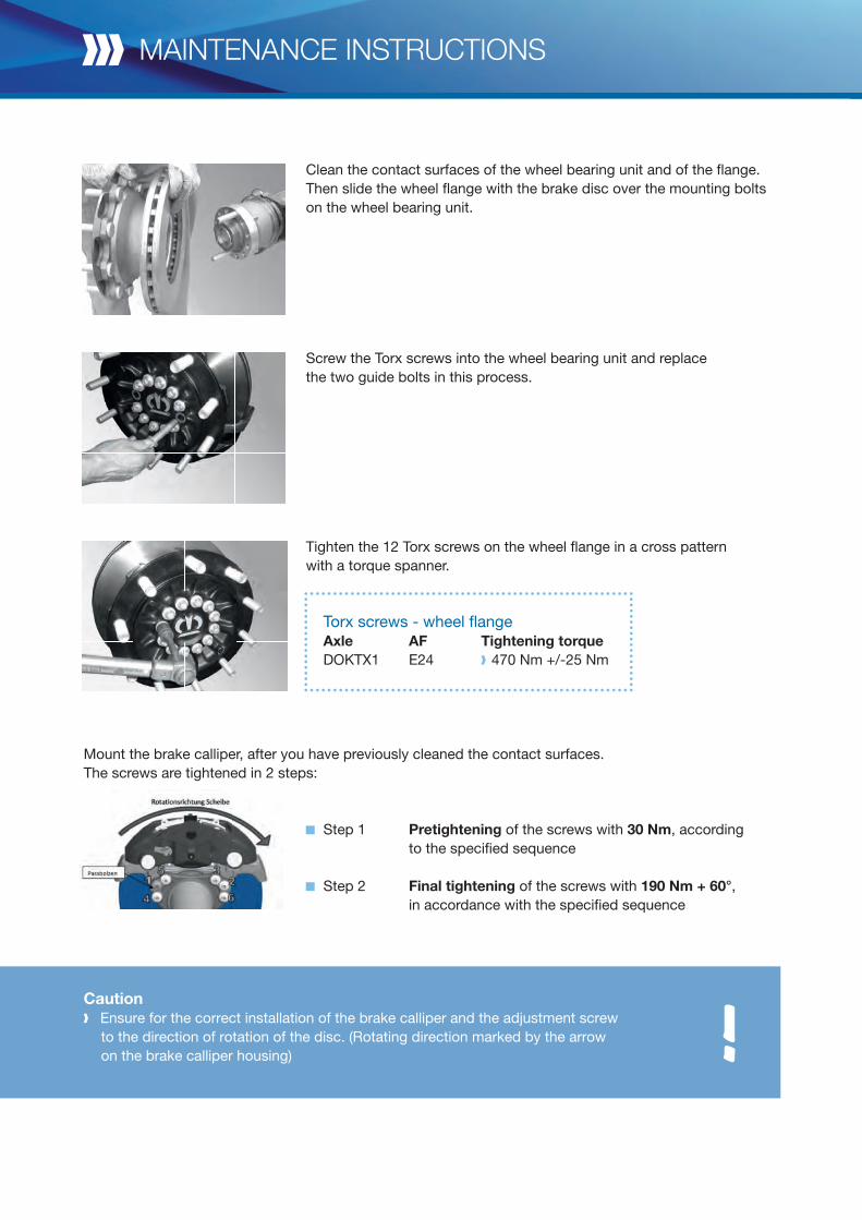
Clean the contact surfaces of the wheel bearing unit and of the flange. Then slide the wheel flange with the brake disc over the mounting bolts on the wheel bearing unit.
Screw the Torx screws into the wheel bearing unit and replace the two guide bolts in this process.
Tighten the 12 Torx screws on the wheel flange in a cross pattern with a torque spanner.
Torx screws - wheel fl ange Axle AF Tightening torque DOKTX1 E24 470 Nm +/-25 Nm
Step 1 Pretightening of the screws with 30 Nm, according to the specified sequence
Step 2 Final tightening of the screws with 190 Nm + 60°, in accordance with the specified sequence
maintenance instructions
Mount the brake calliper, after you have previously cleaned the contact surfaces.The screws are tightened in 2 steps:
!Caution Ensure for the correct installation of the brake calliper and the adjustment screw
to the direction of rotation of the disc. (Rotating direction marked by the arrow on the brake calliper housing)
29
B B
A
5
4
1
2
3
6
8
9
10
7
ø 430 mm 45 mm 37 mm**
MAX. MIN.ø
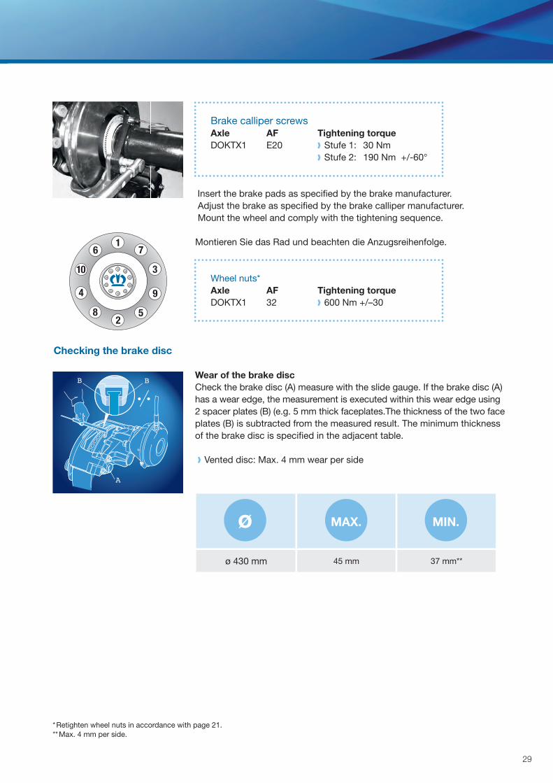
Brake calliper screws Axle AF Tightening torque DOKTX1 E20 Stufe 1: 30 Nm Stufe 2: 190 Nm +/-60°
Insert the brake pads as specified by the brake manufacturer. Adjust the brake as specified by the brake calliper manufacturer. Mount the wheel and comply with the tightening sequence.
Montieren Sie das Rad und beachten die Anzugsreihenfolge.
Wheel nuts* Axle AF Tightening torque DOKTX1 32 600 Nm +/–30
Wear of the brake disc Check the brake disc (A) measure with the slide gauge. If the brake disc (A) has a wear edge, the measurement is executed within this wear edge using 2 spacer plates (B) (e.g. 5 mm thick faceplates.The thickness of the two face plates (B) is subtracted from the measured result. The minimum thickness of the brake disc is specified in the adjacent table. Vented disc: Max. 4 mm wear per side
Checking the brake disc
* Retighten wheel nuts in accordance with page 21.** Max. 4 mm per side.
repair instructions
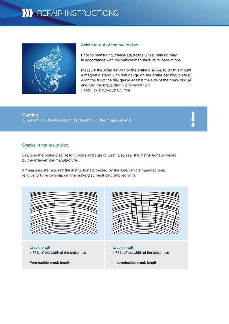
Axial run-out of the brake disc
Prior to measuring, check/adjust the wheel bearing play in accordance with the vehicle manufacturer’s instructions.
Measure the Axial run-out of the brake disc (A), to do this mount a magnetic stand with dial gauge on the brake backing plate (3). Align the tip of the dial gauge against the side of the brake disc (A) and turn the brake disc > one revolution. Max. axial run-out: 0.5 mm
Caution Do not include wheel bearing clearance in the measurement! !
Crack length:< 75% of the width of the brake disc
Permissible crack length
Crack length:> 75% of the width of the brake disc
Impermissible crack length
Cracks in the brake disc
Examine the brake disc (A) for cracks and sign of wear, also see the instructions provided by the axle/vehicle manufacturer.
If measures are required the instructions provided by the axle/vehicle manufacturer, relative to turning/replacing the brake disc must be complied with.
A
3
31
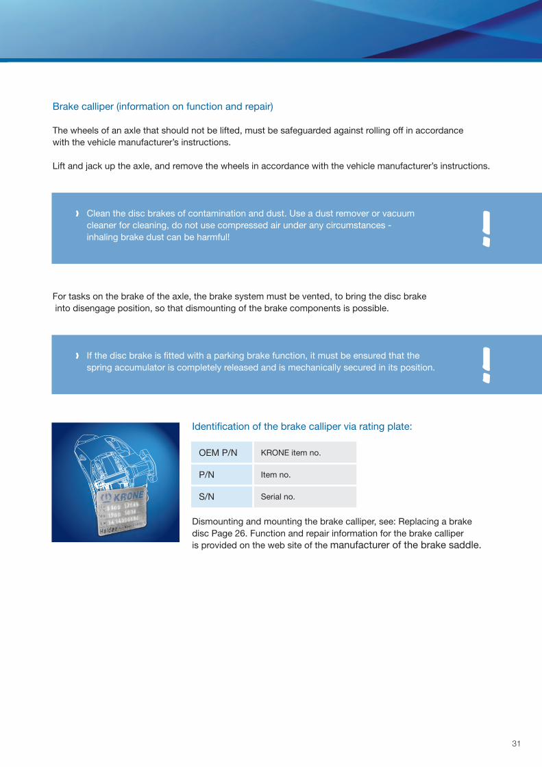
OEM P/N KRONE item no.
P/N Item no.
S/N Serial no.
If the disc brake is fitted with a parking brake function, it must be ensured that the spring accumulator is completely released and is mechanically secured in its position.
!
!
Brake calliper (information on function and repair)
The wheels of an axle that should not be lifted, must be safeguarded against rolling off in accordance with the vehicle manufacturer’s instructions.
Lift and jack up the axle, and remove the wheels in accordance with the vehicle manufacturer’s instructions.
For tasks on the brake of the axle, the brake system must be vented, to bring the disc brake into disengage position, so that dismounting of the brake components is possible.
Identifi cation of the brake calliper via rating plate:
Dismounting and mounting the brake calliper, see: Replacing a brake disc Page 26. Function and repair information for the brake calliper is provided on the web site of the manufacturer of the brake saddle.
Clean the disc brakes of contamination and dust. Use a dust remover or vacuum cleaner for cleaning, do not use compressed air under any circumstances - inhaling brake dust can be harmful!
repair instructions
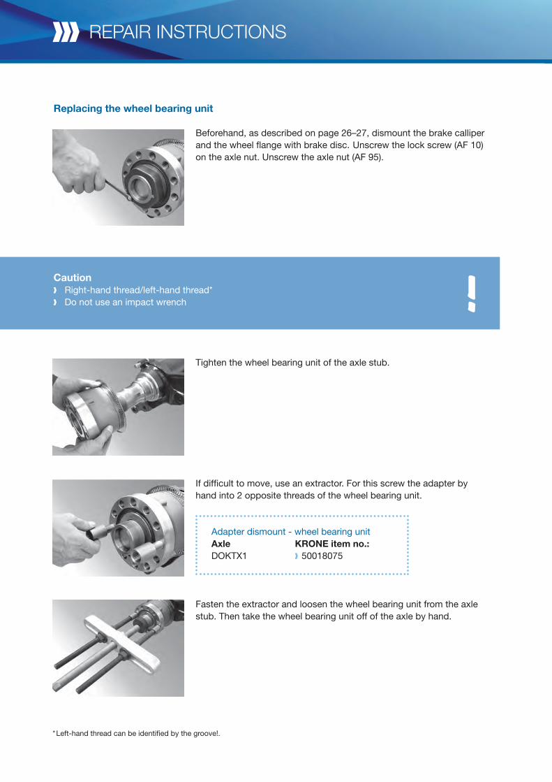
Beforehand, as described on page 26–27, dismount the brake calliper and the wheel flange with brake disc. Unscrew the lock screw (AF 10) on the axle nut. Unscrew the axle nut (AF 95).
Tighten the wheel bearing unit of the axle stub.
If difficult to move, use an extractor. For this screw the adapter by hand into 2 opposite threads of the wheel bearing unit.
Adapter dismount - wheel bearing unit Axle KRONE item no.: DOKTX1 50018075
Fasten the extractor and loosen the wheel bearing unit from the axle stub. Then take the wheel bearing unit off of the axle by hand.
* Left-hand thread can be identified by the groove!.
Caution Right-hand thread/left-hand thread* Do not use an impact wrench !
Replacing the wheel bearing unit
33
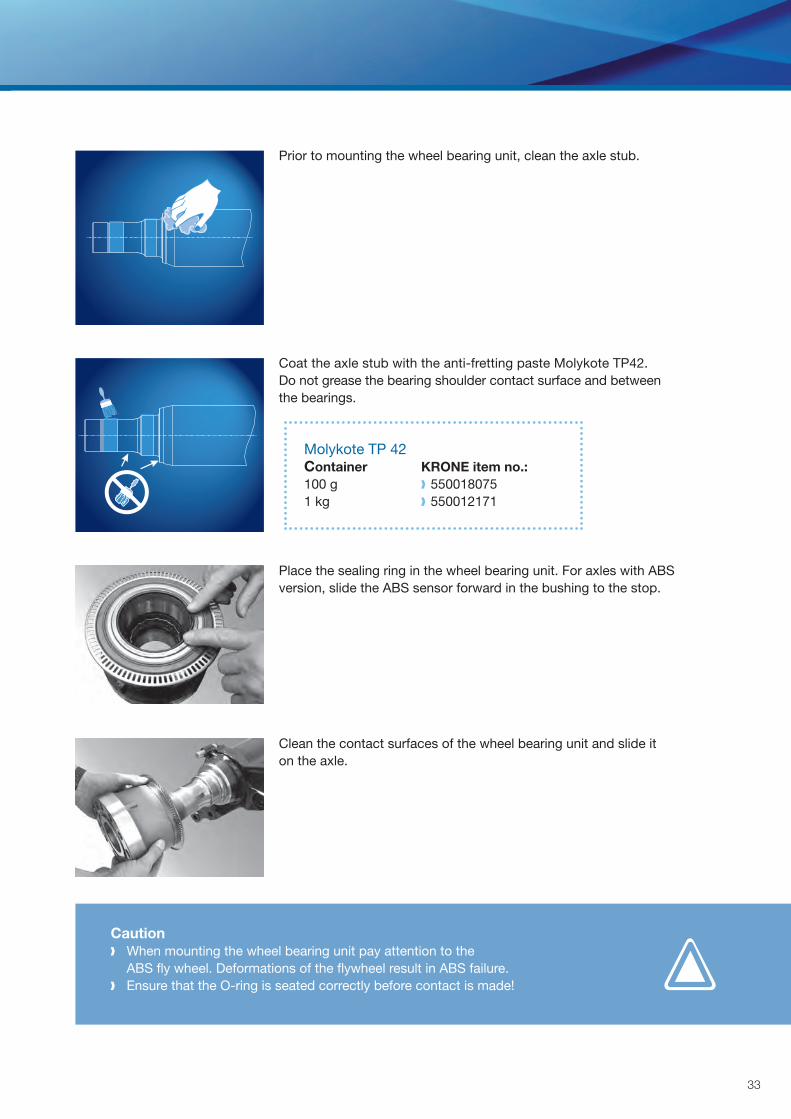
Prior to mounting the wheel bearing unit, clean the axle stub.
Coat the axle stub with the anti-fretting paste Molykote TP42.Do not grease the bearing shoulder contact surface and between the bearings.
Molykote TP 42 Container KRONE item no.: 100 g 550018075 1 kg 550012171
Place the sealing ring in the wheel bearing unit. For axles with ABS version, slide the ABS sensor forward in the bushing to the stop.
Clean the contact surfaces of the wheel bearing unit and slide it on the axle.
Caution When mounting the wheel bearing unit pay attention to the
ABS fly wheel. Deformations of the flywheel result in ABS failure. Ensure that the O-ring is seated correctly before contact is made!
!
!
!Lightly grease the thread of the contact surfaces and the thread of the axle nut.
Caution Ensure that the ABS sensor rests on the flywheel!
repair instructions
Caution Do not deform the flywheel!
Caution Left-hand thread/right-hand thread* Do not use an impact wrench
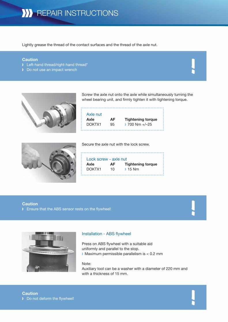
Screw the axle nut onto the axle while simultaneously turning the wheel bearing unit, and firmly tighten it with tightening torque.
Axle nut Axle AF Tightening torque DOKTX1 95 700 Nm +/–25
Secure the axle nut with the lock screw.
Lock screw - axle nut Axle AF Tightening torque DOKTX1 10 15 Nm
Installation - ABS fl ywheel
Press on ABS flywheel with a suitable aid uniformly and parallel to the stop. Maximum permissible parallelism is < 0.2 mm
Note: Auxiliary tool can be a washer with a diameter of 220 mm andwith a thickness of 15 mm.
35
!
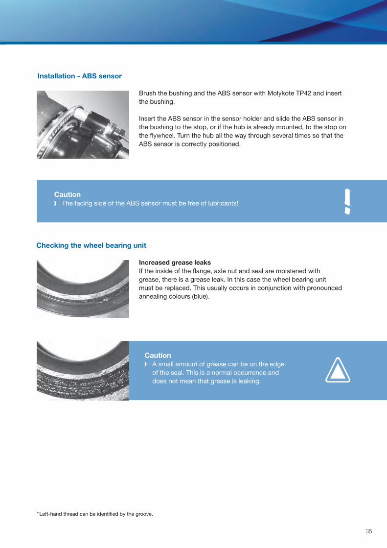
Brush the bushing and the ABS sensor with Molykote TP42 and insert the bushing.
Insert the ABS sensor in the sensor holder and slide the ABS sensor in the bushing to the stop, or if the hub is already mounted, to the stop on the flywheel. Turn the hub all the way through several times so that the ABS sensor is correctly positioned.
Caution The facing side of the ABS sensor must be free of lubricants!
Caution A small amount of grease can be on the edge
of the seal. This is a normal occurrence and does not mean that grease is leaking.
Increased grease leaksIf the inside of the flange, axle nut and seal are moistened with grease, there is a grease leak. In this case the wheel bearing unit must be replaced. This usually occurs in conjunction with pronounced annealing colours (blue).
Installation - ABS sensor
Checking the wheel bearing unit
* Left-hand thread can be identified by the groove.
repair instructions
Noise check
Lift the wheel. Turn the wheel in both directions.If the bearing feels rough and the „grinding“ noise can be heard, replace the wheel bearing unit.
Caution A ticking or clicking noise is normal, because the bearing, in spite of the lifted wheel,
is not under load and thus the rollers are not aligned, and consequently can move in the axial direction.
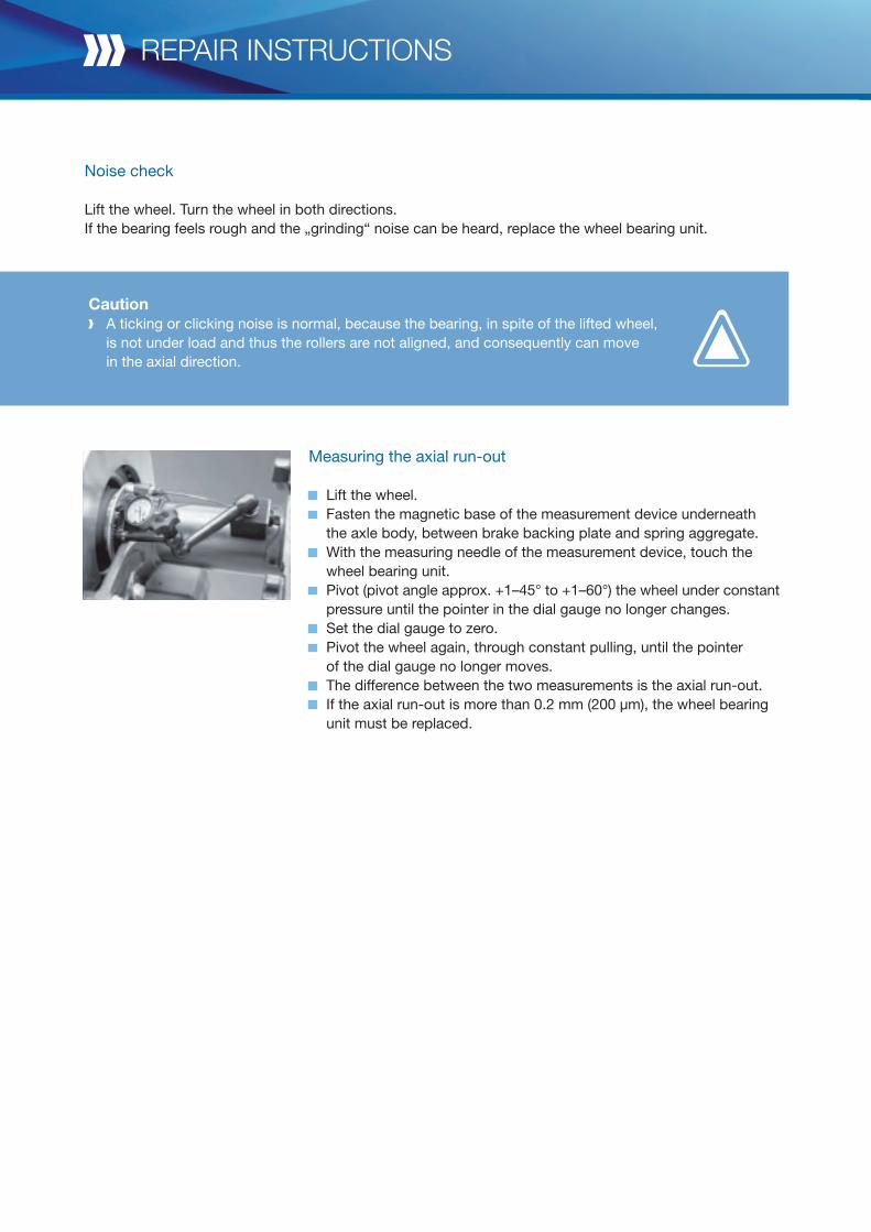
Measuring the axial run-out
Lift the wheel. Fasten the magnetic base of the measurement device underneath
the axle body, between brake backing plate and spring aggregate. With the measuring needle of the measurement device, touch the
wheel bearing unit. Pivot (pivot angle approx. +1–45° to +1–60°) the wheel under constant
pressure until the pointer in the dial gauge no longer changes. Set the dial gauge to zero. Pivot the wheel again, through constant pulling, until the pointer
of the dial gauge no longer moves. The difference between the two measurements is the axial run-out. If the axial run-out is more than 0.2 mm (200 μm), the wheel bearing
unit must be replaced.
37
Spare parts data sheetsAxle
Item Item no. Description Quantity*
1 On demand Axle body 1
2 550017647 Brake calliper 4345 DBT22LT, left 1
2 550017648 Brake calliper 4345 DBT22LT, right 1
3 550017646 Set brake pads 4345 DBT22LT 1
4 550017801 Kit screws for 1 brake 2
* Quantity per axle set.
repair instructions
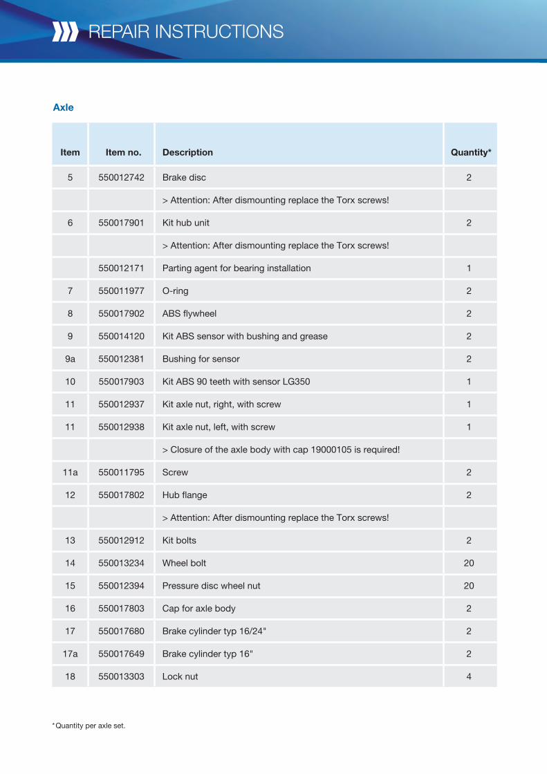
Axle
* Quantity per axle set.
Item Item no. Description Quantity*
5 550012742 Brake disc 2
> Attention: After dismounting replace the Torx screws!
6 550017901 Kit hub unit 2
> Attention: After dismounting replace the Torx screws!
550012171 Parting agent for bearing installation 1
7 550011977 O-ring 2
8 550017902 ABS flywheel 2
9 550014120 Kit ABS sensor with bushing and grease 2
9a 550012381 Bushing for sensor 2
10 550017903 Kit ABS 90 teeth with sensor LG350 1
11 550012937 Kit axle nut, right, with screw 1
11 550012938 Kit axle nut, left, with screw 1
> Closure of the axle body with cap 19000105 is required!
11a 550011795 Screw 2
12 550017802 Hub flange 2
> Attention: After dismounting replace the Torx screws!
13 550012912 Kit bolts 2
14 550013234 Wheel bolt 20
15 550012394 Pressure disc wheel nut 20
16 550017803 Cap for axle body 2
17 550017680 Brake cylinder typ 16/24" 2
17a 550017649 Brake cylinder typ 16" 2
18 550013303 Lock nut 4
39
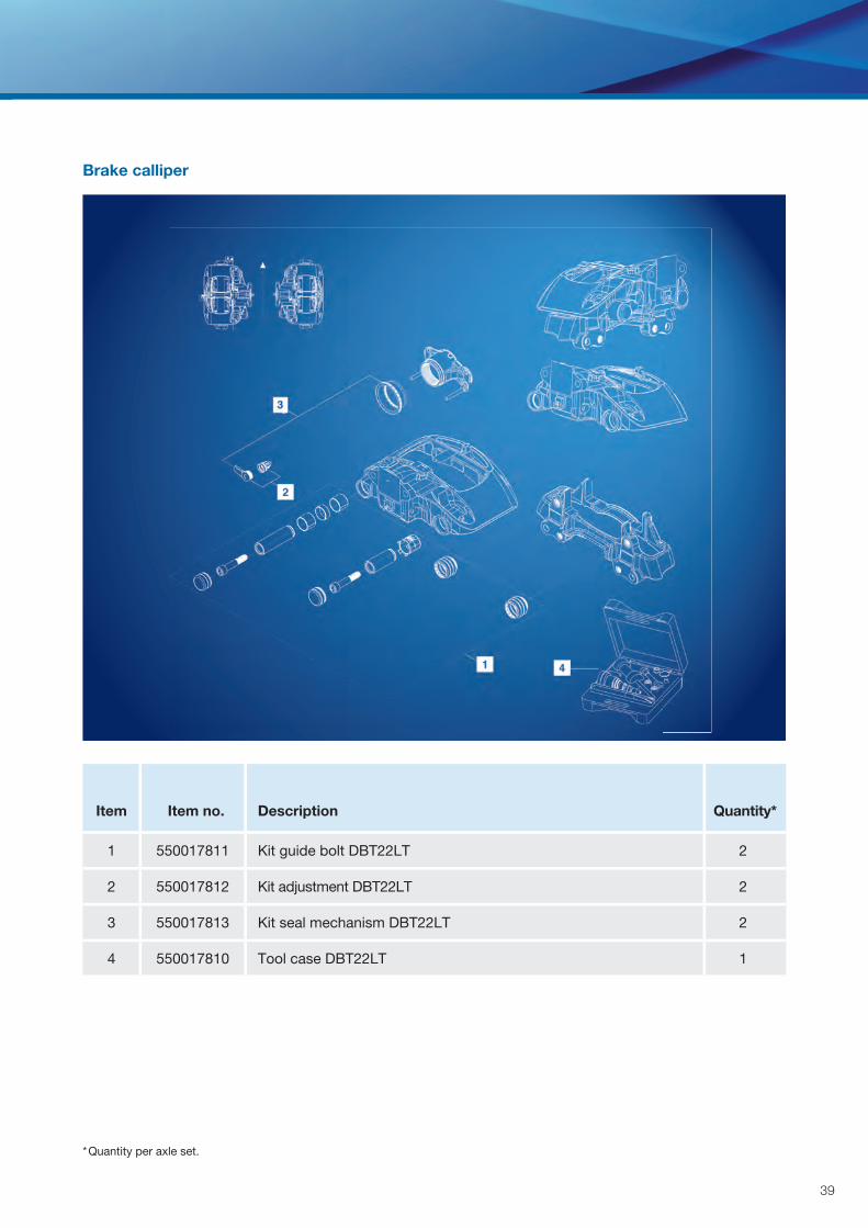
Brake calliper
* Quantity per axle set.
Item Item no. Description Quantity*
1 550017811 Kit guide bolt DBT22LT 2
2 550017812 Kit adjustment DBT22LT 2
3 550017813 Kit seal mechanism DBT22LT 2
4 550017810 Tool case DBT22LT 1
repair instructions
* Quantity per axle set.
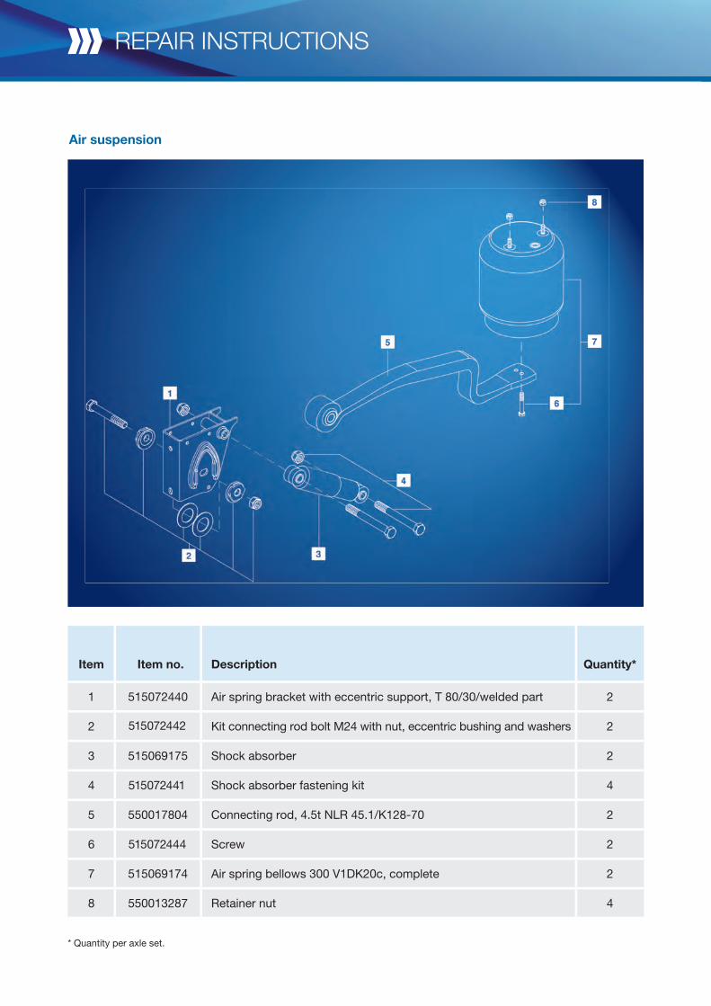
Air suspension
Item Item no. Description Quantity*
1 515072440 Air spring bracket with eccentric support, T 80/30/welded part 2
2 515072442 Kit connecting rod bolt M24 with nut, eccentric bushing and washers 2
3 515069175 Shock absorber 2
4 515072441 Shock absorber fastening kit 4
5 550017804 Connecting rod, 4.5t NLR 45.1/K128-70 2
6 515072444 Screw 2
7 515069174 Air spring bellows 300 V1DK20c, complete 2
8 550013287 Retainer nut 4
41
Integration
* Quantity per axle set.
Item Item no. Description Quantity*
1 550017805 Kit spring-loaded bar R64.5, fl at with nuts and washers 4
2 550017806 Retainer nut 8
3 550013256 Washer 8
4 550017807 Clamp plate one-piece 2
5 550017808 Shim 2
6 550017809 Centre bolt 2
repair instructions
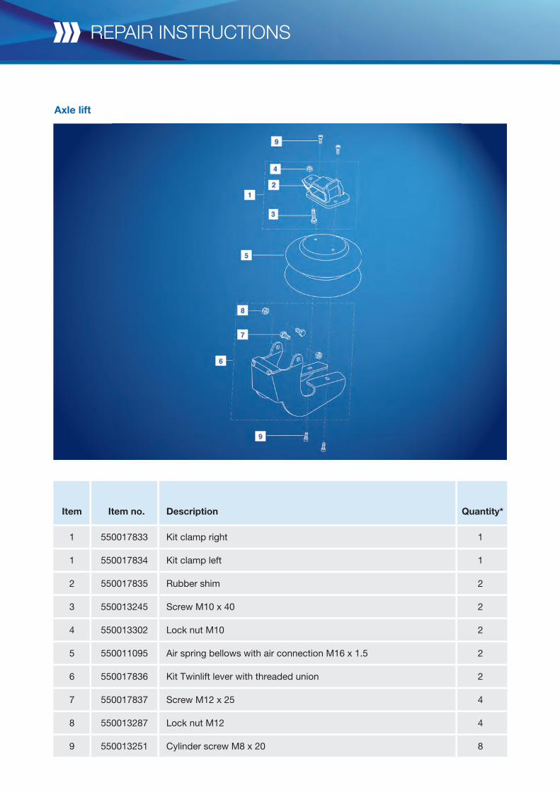
Axle lift
Item Item no. Description Quantity*
1 550017833 Kit clamp right 1
1 550017834 Kit clamp left 1
2 550017835 Rubber shim 2
3 550013245 Screw M10 x 40 2
4 550013302 Lock nut M10 2
5 550011095 Air spring bellows with air connection M16 x 1.5 2
6 550017836 Kit Twinlift lever with threaded union 2
7 550017837 Screw M12 x 25 4
8 550013287 Lock nut M12 4
9 550013251 Cylinder screw M8 x 20 8
43
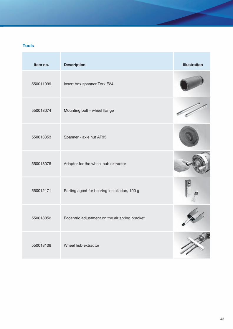
Tools
Item no. Description Illustration
550011099 Insert box spanner Torx E24
550018074 Mounting bolt - wheel fl ange
550013353 Spanner - axle nut AF95
550018075 Adapter for the wheel hub extractor
550012171 Parting agent for bearing installation, 100 g
550018052 Eccentric adjustment on the air spring bracket
550018108 Wheel hub extractor
Testing and warning instructions
Current KRONE service information atwww.krone-trailer.com
repair instructions
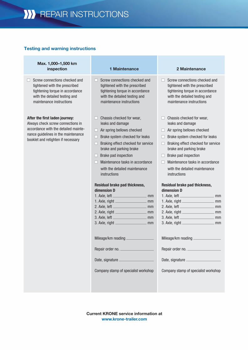
Max. 1,000–1,500 km inspection 1 Maintenance 2 Maintenance
Screw connections checked and tightened with the prescribed tightening torque in accordance with the detailed testing and maintenance instructions
After the first laden journey:Always check screw connections in accordance with the detailed mainte-nance guidelines in the maintenance booklet and retighten if necessary
Screw connections checked and tightened with the prescribed tightening torque in accordance with the detailed testing and maintenance instructions
Chassis checked for wear, leaks and damage
Air spring bellows checked
Brake system checked for leaks
Braking effect checked for service brake and parking brake
Brake pad inspection
Maintenance tasks in accordance
with the detailed maintenance instructions
Residual brake pad thickness, dimension D1. Axle, left mm1. Axle, right mm2. Axle, left mm2. Axle, right mm3. Axle, left mm3. Axle, right mm
Mileage/km reading
Repair order no.
Date, signature
Company stamp of specialist workshop

45
Current KRONE service information atwww.krone-trailer.com
3 Maintenance 4 Maintenance 5 Maintenance
Screw connections checked and tightened with the prescribed tightening torque in accordance with the detailed testing and maintenance instructions
Chassis checked for wear, leaks and damage
Air spring bellows checked
Brake system checked for leaks
Braking effect checked for service brake and parking brake
Brake pad inspection
Maintenance tasks in accordance
with the detailed maintenance instructions
Residual brake pad thickness, dimension D1. Axle, left mm1. Axle, right mm2. Axle, left mm2. Axle, right mm3. Axle, left mm3. Axle, right mm
Mileage/km reading
Repair order no.
Date, signature
Company stamp of specialist workshop
Screw connections checked and tightened with the prescribed tightening torque in accordance with the detailed testing and maintenance instructions
Chassis checked for wear, leaks and damage
Air spring bellows checked
Brake system checked for leaks
Braking effect checked for service brake and parking brake
Brake pad inspection
Maintenance tasks in accordance
with the detailed maintenance instructions
Residual brake pad thickness,dimension D1. Axle, left mm1. Axle, right mm2. Axle, left mm2. Axle, right mm3. Axle, left mm3. Axle, right mm
Mileage/km reading
Repair order no.
Date, signature
Company stamp of specialist workshop
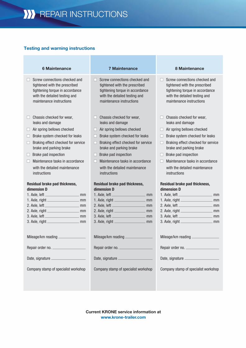
6 Maintenance 7 Maintenance 8 Maintenance
Screw connections checked and tightened with the prescribed tightening torque in accordance with the detailed testing and maintenance instructions
Chassis checked for wear, leaks and damage
Air spring bellows checked
Brake system checked for leaks
Braking effect checked for service brake and parking brake
Brake pad inspection
Maintenance tasks in accordance
with the detailed maintenance instructions
Residual brake pad thickness, dimension D1. Axle, left mm1. Axle, right mm2. Axle, left mm2. Axle, right mm3. Axle, left mm3. Axle, right mm
Mileage/km reading
Repair order no.
Date, signature
Company stamp of specialist workshop
Screw connections checked and tightened with the prescribed tightening torque in accordance with the detailed testing and maintenance instructions
Chassis checked for wear, leaks and damage
Air spring bellows checked
Brake system checked for leaks
Braking effect checked for service brake and parking brake
Brake pad inspection
Maintenance tasks in accordance
with the detailed maintenance instructions
Residual brake pad thickness,dimension D1. Axle, left mm1. Axle, right mm2. Axle, left mm2. Axle, right mm3. Axle, left mm3. Axle, right mm
Mileage/km reading
Repair order no.
Date, signature
Company stamp of specialist workshop
Screw connections checked and tightened with the prescribed tightening torque in accordance with the detailed testing and maintenance instructions
Chassis checked for wear, leaks and damage
Air spring bellows checked
Brake system checked for leaks
Braking effect checked for service brake and parking brake
Brake pad inspection
Maintenance tasks in accordance
with the detailed maintenance instructions
Residual brake pad thickness,dimension D1. Axle, left mm1. Axle, right mm2. Axle, left mm2. Axle, right mm3. Axle, left mm3. Axle, right mm
Mileage/km reading
Repair order no.
Date, signature
Company stamp of specialist workshop
Testing and warning instructions
Current KRONE service information atwww.krone-trailer.com
repair instructions

47
Current KRONE service information atwww.krone-trailer.com
9 Maintenance 10 Maintenance 11 Maintenance
Screw connections checked and tightened with the prescribed tightening torque in accordance with the detailed testing and maintenance instructions
Chassis checked for wear, leaks and damage
Air spring bellows checked
Brake system checked for leaks
Braking effect checked for service brake and parking brake
Brake pad inspection
Maintenance tasks in accordance
with the detailed maintenance instructions
Residual brake pad thickness, dimension D1. Axle, left mm1. Axle, right mm2. Axle, left mm2. Axle, right mm3. Axle, left mm3. Axle, right mm
Mileage/km reading
Repair order no.
Date, signature
Company stamp of specialist workshop
Screw connections checked and tightened with the prescribed tightening torque in accordance with the detailed testing and maintenance instructions
Chassis checked for wear, leaks and damage
Air spring bellows checked
Brake system checked for leaks
Braking effect checked for service brake and parking brake
Brake pad inspection
Maintenance tasks in accordance
with the detailed maintenance instructions
Residual brake pad thickness,dimension D1. Axle, left mm1. Axle, right mm2. Axle, left mm2. Axle, right mm3. Axle, left mm3. Axle, right mm
Mileage/km reading
Repair order no.
Date, signature
Company stamp of specialist workshop
Screw connections checked and tightened with the prescribed tightening torque in accordance with the detailed testing and maintenance instructions
Chassis checked for wear, leaks and damage
Air spring bellows checked
Brake system checked for leaks
Braking effect checked for service brake and parking brake
Brake pad inspection
Maintenance tasks in accordance
with the detailed maintenance instructions
Residual brake pad thickness,dimension D1. Axle, left mm1. Axle, right mm2. Axle, left mm2. Axle, right mm3. Axle, left mm3. Axle, right mm
Mileage/km reading
Repair order no.
Date, signature
Company stamp of specialist workshop
OPERATOR MANUAL
FAHRzEUGWERK BERNARD KRONE GMBHBernard-Krone-Straße 1, 49757 Werlte, GermanyPhone: +49 (0) 5951 209-0, Fax: +49 (0) 5951 24 65 [email protected], www.krone-trailer.com
If you have any questions: just give us a call!We are available per telephone or on-site for personal consultation.
Your KRONE contact partnerS
ubje
ct to
cha
nges
; ver
sion
: 09/
2014
; Pho
tos:
09/
2014
; Pho
tos:
Fah
rzeu
gwer
k B
erna
rd K
rone
Gm
bH, ©
ww
w.is
tock
phot
o.co
m