Embed Size (px)
Citation preview

MAN2577 V6 Revision: March 2005
FireFinderTM
EN54 Parts 2 & 4 FFiirree AAllaarrmm CCoonnttrrooll PPaanneell
ˆ Our aim is to provide û Consistently Excellent Service ø in the eyes of our customers ˜
Owner Operator Manual for
ConfigManager V6
EARTH FAULT
FWRE ACTIVE
SYSTEM FAULT
SUPPLY FAULT
POWER ON
PRE-ALARM
TEST MODE
SOUNDERFAULT/DISABLED
EVACUATESOUNDER SILENCE
PREVIOUS NEXT BUZZERSILENCE
SOUNDER DISABLE
RESET
DISABLED
FIRE
FAULT
FAREFAULT/DISABLE
FWREFAULT/DISABLE
OUTPUTDELAY ACTIVE
DEVICEDISABLE/ENABLE
LOOP 1ABC
2DEF GHI
3
DEVICE JKL4
MNO5
PQRS6
ZONE TUV7 8
WXYZ9
SYMB
TO 0SPACE ENTERDISPLAY FUNCTIONMENU
CANCEL ENTRY
FARE ACTIVE
CLOSEDOPEN
CLOSEDOPEN
CLOSEDOPEN
CLOSEDOPEN
CLOSED
CLOSED
CLOSEDOPEN
CLOSEDOPEN
CLOSEDOPEN
CLOSEDOPEN
CLOSEDOPEN
CLOSEDOPEN
CLOSEDOPEN
CLOSEDOPEN
OPEN
CLOSEDOPEN
OPEN
CLOSEDOPEN
CLOSEDOPEN
CLOSEDOPEN
CLOSEDOPEN
CLOSEDOPEN
CLOSED
CLOSED
CLOSEDOPEN
CLOSEDOPEN
CLOSEDOPEN
CLOSEDOPEN
CLOSEDOPEN
CLOSEDOPEN
CLOSEDOPEN
CLOSEDOPEN
OPEN
CLOSEDOPEN
OPEN
CLOSEDOPEN
TP
FIREFINDER 16/2/2003 14.31.15AMPAC EUROPE LTDPH: +44 (0) 1254 880201SYSTEM IS NORMAL
AC:1S ALM: 0000 PALM: 0000 DIS: 0000


Ampac Europe Limited FireFinder™ Owner Operator Manual
Table Of Contents Page No
1. Non Disclosure Agreement ................................................................................... 1
2. About This Manual ................................................................................................. 2
2.1 Purpose......................................................................................................................................2
2.2 Scope .........................................................................................................................................2
2.3 References.................................................................................................................................2
3. FireFinderTM Control Panel .................................................................................... 2
4. Functions and Menus ............................................................................................ 6
4.1 The Default LCD Display ..........................................................................................................6
4.2 Accessing Functions and Menus............................................................................................6
4.3 Function Menu and Access Levels .........................................................................................6
5. The Main Menu ....................................................................................................... 7
5.1 Status Menu...............................................................................................................................7
5.2 Testing Menu .............................................................................................................................9
5.3 Sounders....................................................................................................................................9
5.4 Printer Menu ..............................................................................................................................9
6. Main Functions..................................................................................................... 10
6.1 Setting the Function Date Facility .........................................................................................10
6.2 Setting the Function Time Facility ........................................................................................10
6.3 Setting the Function Daynight Facility .................................................................................10
6.4 Function Logs Facility............................................................................................................11
6.5 The Function Test Facility......................................................................................................11
6.6 Function Manual I/O Control..................................................................................................12
6.7 Function Programming ..........................................................................................................13
6.7.1 Conventional Zone Programming..........................................................................13
6.7.2 Device Programming...............................................................................................14
6.7.3 Input Programming .................................................................................................15
6.7.4 Output Programming ..............................................................................................15
6.7.5 Watchdog .................................................................................................................15
6.8 Extra Devices Detected ..........................................................................................................15
6.9 Function Passwords...............................................................................................................16
6.9.1 Forgotten Passwords..............................................................................................16
6.10 The Function Language .........................................................................................................16
7. Incoming Fire Alarm Signal................................................................................. 17
8. Accessing a Loop, Sensor or Zone .................................................................... 17
9. Certification Information...................................................................................... 18
10. Glossary of Terms................................................................................................ 19
11. Definitions............................................................................................................. 20
12. Quick Reference Guides...................................................................................... 21

Ampac Europe Limited FireFinder™ Owner Operator Manual
Page 1
1. Non Disclosure Agreement This contract has been entered into by the person or company user of this document (hereafter called the Trader) and AMPAC Technologies (hereafter called AMPAC) of 97 Walters Drive, Osborne Park Western Australia 6017. Under terms and conditions as specified hereunder. Whereas AMPAC and the Trader for their mutual benefit and pursuant to a working relationship which may be established, anticipate that AMPAC will disclose in the form of this document, information of a secret, or confidential or proprietary nature (hereinafter collectively referred to as Proprietary Information). Whereas AMPAC desires to ensure that the confidentiality of any Proprietary Information is maintained in accordance with the terms of this Agreement; NOW, THEREFORE, in consideration of the foregoing premises, and the mutual covenants contained herein, the Trader hereby agrees as follows: 1. The Trader shall hold in trust and confidence, and not disclose to any person outside its
organisation, any Proprietary information which is disclosed to the Trader by AMPAC under this Agreement. Proprietary Information disclosed under this Agreement may be used by the Trader only for the purpose of carrying out work on or with AMPAC supplied equipment and may not be used for any other purpose whatsoever.
2. The Trader shall disclose Proprietary Information received by AMPAC under this Agreement to
persons within its organisation only if such persons are legally bound in writing to protect the confidentiality of such Proprietary Information.
3. The undertakings and obligations of the Trader under this Agreement shall not apply to any
Proprietary Information which :
1. Is disclosed in a printed publication available to the public, is described in patent anywhere in the world, or is otherwise in the public domain at the time of disclosure;
2. Is generally disclosed to third parties by AMPAC without restriction on such third parties; 3. Is shown by the Trader to have been in its possession prior to the receipt thereof from
AMPAC; 4. Is approved for release by written authorisation of AMPAC; or 5. Is not designated by AMPAC in writing or by appropriate stamp or legend to be of a secret,
confidential or proprietary nature. 4. This Agreement will be binding upon and inure to the benefit of the parties hereto, and their
respective successors and assigns. 5. This Agreement, and all rights and obligations hereunder, shall expire on the 10th anniversary of
the date of issue of this document. These terms are accepted by the Trader on receipt and retention of this document.

Ampac Europe Limited FireFinder™ Owner Operator Manual
Page 2
2. About This Manual
2.1 Purpose The purpose of this manual is to give direction in the operation of the FireFinder™ Fire Alarm Control Panel ( FACP ) with Version 6 software installed.
2.2 Scope The information within this manual is only available to and for the use of personnel engaged in the installation and operation of the FireFinder™ Fire Detection System.
FireFinder has been designed to comply with major world standards. To ensure these standards are not compromised in any way installation staff and operators should;
1. be qualified and trained for the task they undertake;
2. be familiar with the contents of this manual prior to the installation and commissioning of the
FireFinder F.A.C.P.; and
3. be aware that if a problem is encountered or there is any doubt with respect to the operational parameters of the installation the supplier should be contacted.
2.3 References FireFinder™ Technical Manual
FireFinder™ Installation and Commissioning Manual
British Standard: EN54 Parts 2 & 4
3. FireFinderTM Control Panel
Fig 1: The FireFinder™ Control Panel
EARTH FAULT
FWRE ACTIVE
SYSTEM FAULT
SUPPLY FAULT
POWER ON
PRE-ALARM
TEST MODE
SOUNDERFAULT/DISABLED
EVACUATESOUNDER SILENCE
PREVIOUS NEXT BUZZERSILENCE
SOUNDER DISABLE
RESET
DISABLED
FIRE
FAULT
FAREFAULT/DISABLE
FWREFAULT/DISABLE
OUTPUTDELAY ACTIVE
DEVICEDISABLE/ENABLE
LOOP 1ABC
2DEF GHI
3
DEVICE JKL4
MNO5
PQRS6
ZONE TUV7 8
WXYZ9
SYMB
TO 0SPACE ENTERDISPLAY FUNCTIONMENU
CANCEL ENTRY
FARE ACTIVE
FIREFINDER 16/2/2003 14.31.15AMPAC EUROPEPH: 44(0)1254 880 201SYSTEM IS NORMAL
AC:1S ALM: 0000 PALM: 0000 DIS: 0000

Ampac Europe Limited FireFinder™ Owner Operator Manual
Page 3
1. FIRE
FIRE (Red) – This LED will light steady if any fire alarms are present on the system.
2. FAULT
FAULT (Yellow) – This LED will light steady if there are any faults on the system, whether they are loop faults, module faults, device faults etc.
3. DISABLED
DISABLED (Yellow) – The LED will light steady if any detectors, devices or zones in the system have been disabled or if an output relay has been de-activated. The display will show the conditions as per EN54 9.2 and 9.4.2.
4.
SOUNDER SILENCE
SOUNDER SILENCE- Pressing this button will silence any Bells or Sounders (activated either by a fire alarm or by manual evacuation) connected to the fire panel. If the bells or sounders are silenced the LED just above the button will glow steady and the EVACUATE LED will turn off. A new Fire Alarm will reactivate the Bell and Sounders.
5. EVACUATE
EVACUATE – Pressing this button will activate the Sounders and Bells. The LED just above the button will light steady. The LED above the Sounder Silence will turn off.
6.
PREVIOUS
PREVIOUS – This button is used for scrolling backwards through fire alarms, faults, or disablement’s on the LCD.
7.
NEXT
NEXT – This button is used for scrolling forwards through fire alarms, faults, or disables on the LCD.
8.
BUZZERSILENCE
BUZZER SILENCE – Pressing this button will silence the panel sounder, which sounds whenever there is a fire alarm or fault. The sound for a fire alarm is a steady sound where as for a fault it is an intermittent sound.
9. RESET
RESET – Pressing this button will reset the panel, clearing any fire alarms and taking the LCD display back to its default screen, unless there are any uncleared faults or disabled devices, these will continue to be displayed.
10.
SOUNDER DISABLE
SOUNDER DISABLE – This button is used to disable the Bells or Sounders. A new fire alarm will not activate the Bells or Sounders. The Evacuate Button will not activate the Bells/Sounders while it is disabled.
11. POWER ON
POWER ON (Green) – This LED will be illuminated when power is connected to the FACP and switched on.
12. PRE-ALARM
PRE-ALARM (Red) – This LED will light when a sensor/detector is in the pre-alarm state.

Ampac Europe Limited FireFinder™ Owner Operator Manual
Page 4
13. TEST MODE
TEST MODE (Yellow) – This LED will light when the panel is in any of the test modes.
14. SOUNDERFAULT/DISABLED SOUNDER FAULT / DISABLE (Yellow) – This LED will flash when there is a
fault on the external sounder output. The LED will go steady if the sounder is disabled. If the sounder is both in fault and disabled the LED will flash and then go steady in a cycle.
15. SUPPLY FAULT
SUPPLY FAULT (Yellow) – This LED will light when there is a supply fault. The following conditions constitute a fault.
� Mains power is not available. � The output voltage is too low. � The output voltage is too high. � The battery is not connected properly or has failed.
16. EARTH FAULT
EARTH FAULT (Yellow) – This LED will light if there is an earth fault (+ or -) on any of the signal cables of the system.
17. SYSTEM FAULT
SYSTEM FAULT (Yellow) – This LED will light if the main system CPU is in fault.
18. FWRE ACTIVE
F.W.R.E (Fault Warning Routing Equipment) ACTIVE (Yellow) – This LED will light when the FWRE output is active.
19. FARE ACTIVE
F.A.R.E (Fire Alarm Routing Equipment) ACTIVE (Red) – This LED will light when the FARE output is active.
20.
DEVICEDISABLE/ENABLE
DEVICE DISABLE / ENABLE – This button is used to disable individual or groups of detectors, devices or zones.
21.
FWREFAULT/DISABLE
F.W.R.E FAULT / DISABLE – Pressing this button will disable the FWRE output relay on the Output board. If disabled the associated LED will light. Pressing the button again will re-enable the FWRE relay. The LED will also light if the FWRE is in fault.
22.
FAREFAULT/DISABLE
F.A.R.E FAULT / DISABLE – Pressing this button will disable the FARE output relay on the Output board. If disabled the associated LED will light. Pressing the button again will re-enable the FARE relay. The LED will also light if the FARE is in fault.
23.
OUTPUTDELAY ACTIVE
OUTPUT DELAY ACTIVE – Future option, not yet available.
24. LOOP
LOOP – Press this button followed by a number to select the loop you wish to access, eg LOOP 4.
25. DEVICE
DEVICE – After selecting the Loop number using the LOOP button, press the DEVICE button to enter the sensor number for the device you wish to interrogate.

Ampac Europe Limited FireFinder™ Owner Operator Manual
Page 5
26. ZONE
ZONE – Press this button followed by a number eg ZONE 4 to select the required zone.
27. DISPLAY
DISPLAY – Press this button after selecting the Zone number or the Loop and Sensor numbers to display the status of the device.
28.
8WXYZ
THE ALPHA/NUMERIC BUTTONS – These buttons are used to navigate around the panel’s menus and enter data. If you are entering a description, or some other data that contains characters as well as numbers, pressing the buttons multiple times will scroll through the available letters written on the button, in sequence.
29. TO
TO – Use this button to access a range of devices. Eg, 2 TO 7.
30. ENTER
ENTER – Press the ENTER button when prompted to enter data.
31. CANCEL ENTRY
CANCEL – The CANCEL ENTRY button is used to delete any data in the current field or return to the previously displayed menu.
32. SINGLE ARROW BUTTONS – These move the cursor back and forth when entering data into a field.
33. DOUBLE ARROW BUTTONS – These are used to move between fields when entering data.
34. FUNCTIONMENU
MENU / FUNCTION – Pressing the MENU button will display the main menu on the LCD. Similarly pressing the FUNCTION button will display the function menu on the LCD.
35. LCD DISPLAY – This screen can be configured with the servicing companies name and phone number. It also displays the current date, time and if the system is normal (no faults and fire alarms). If there are any faults or fire alarms the LCD will display the device/s in question and the time of the 1st fire alarm.
Fig 2: LCD Default Screen
FIREFINDER 16/2/2003 14.31.15AMPAC EUROPE LTDPH: +44 (0) 1254 880201SYSTEM IS NORMAL
AC:1S ALM: 0000 PALM: 0000 DIS: 0000

Ampac Europe Limited FireFinder™ Owner Operator Manual
Page 6
IMPORTANT NOTE: It is strongly advised that all field changes or programming of a FireFinder™ should be properly
recorded.
4. Functions and Menus
4.1 The Default LCD Display
In its normal state the FireFinder™ will display a screen similar to that shown below.
Fig 3: The Default LCD Display
This screen can be configured with the servicing company’s name and phone number via a laptop or modem only. The current date, time, system status, access levels(AC), total number of alarms (ALM), Pre-alarms (PALM), Faults (FLT) and Disable (DIS) is also displayed.
4.2 Accessing Functions and Menus
All features are password protected (actually a pass-number as it can only contain numbers) to prevent unauthorised tampering with the panel's configuration. A new panel has a pre-programmed password of 3333. Once the customer takes control of the panel the password can be changed to suit their requirements. Note: All menus are provided with screen prompts to guide the operator through the operation.
4.3 Function Menu and Access Levels The FUNCTION MENU provides access to the programming and configuration functions. Three levels of ACCESS are available via separate passwords so that access to certain facilities can be restricted (such as the ability to enter new passwords).
• Level I: Allows access to indications and controls to investigate and respond to a fire or fault warning.
• Level II: In addition to the level I facilities, quiescent, fire alarm fault warning, disable and test conditions.
• Level III: In addition to the level II facilities, reconfigure specific data or control and maintain the panel in accordance with the manufacturers specifications.
• Level IV: In a addition to level III trained and authorised by the manufacturer to repair or alter the firmware of a panel.
FIREFINDER 9/9/2001 13.21.15 SERVICED BY YOUR COMPANY PH: 09 9999 9999 SYSTEM IS NORMAL AC: 1S ALM: 0000 PALM: 0000 FLT: 0 DIS: 0000
FUNCTIONMENUFrom the DEFAULT DISPLAY, press MENU or FUNCTION. This brings up the display for entering a password. Once entered and validated it is possible to access the panel's functions.
Ampac Europe Limited FireFinder™ Owner Operator Manual
Page 7
5. The Main Menu The MAIN MENU is accessed by pressing MENU.
Fig 4: The Main Menu
While in the MAIN MENU press the appropriate number on the keypad view any; FIRE ALARMS, PRE-ALARMS,
� FAULTS; Pressing � brings up a sub-menu from which a more detailed description of a fault can be displayed. Select a field 0 – 7.
� Zones
Sensors
� Loops
� Modules
� Comms
� Power Supply
� Brigade
Test
Failures
Sounders
� DISABLES on the system.
If there are no fire alarms, pre-alarms, faults or disables, a message to that effect will be displayed for approximately 1 to 2 seconds and then the display will return to the Main menu.
5.1 Status Menu � is pressed to access the STATUS MENU.
Fig 5: The Status Menu
From the STATUS MENU the status of all of the system components and settings listed below can be interrogated.
Press;
� Loops: Enter the loop number and it will display its status.
� Modules: Enter the module number and it will display the type, the software version and its
status.
� Supply: This menu item will display the charger voltage, whether or not the power supply is
in fault, if Mains is available and if the battery is correctly fitted.
� Brigade: This will display the status of all of the Output Bell 1 & 2, F.A.R.E., F.W.R.E., Aux
and Brigade Status on the Brigade Output Board (302-6730).
� I/O: The LCD will display the status of an input or output in a panel or a loop.
Enter ( i ) the I/O controller number then the input or output on that controller or, ( ii ) the loop and sensor number and the output on that device.
Once entered the LCD will then display a description of what that input or output does and its current state.
MAIN MENU 0: ALARMS 1 :PREALARMS 2: FAULTS 3: DISABLES 4:STATUS 5 :TEST 6: PRINTER: SELECT NO. AC: 2S ALM: 0000 PALM: 0000 FLT: 0 DIS: 0000
STATUS MENU 0: LOOPS 1 :MODULES 2:P/SUPPLY 3: BRIGADE 4: I/O 5:NETWORK 6 :SYSTEM 7:AVALUES SELECT NO. AC: 3S ALM: 0000 PALM: 0000 FLT: 0000 DIS: 0000

Ampac Europe Limited FireFinder™ Owner Operator Manual
Page 8
Network
� Is pressed to access NETWOK STATUS.
Fig 6: Display Network Status
� Network Points:
Fig 7: Display network Points
Network LCD Screens are: Press or or
� Status � Power Supply � Brigade
Select network point Charger volts Operational Eg. Loop number Battery Detected Non- Op
Mains OK
� Remote Slave Modules:
Select from Network Status, Remote Slave Modules then Module No then ENTER .
Fig 8: Display Remote Slave Modules
� Remote External LED Mimic Modules:
Select from Network Status, Remote External LED Mimic Modules then, NP number then,
ENTER then, External LED Mimic number then, ENTER .
System:
is pressed to access SYSTEM STATUS
Fig 9: Display System Status
DISPLAY NETWORK STATUS 0: NETWORK POINTS 1: REMOTE SLAVE MODULES 2: REMOTE EXTERNAL LED MIMIC MODULES SELECT NO.
AC: 2S ALM: 0000 PALM: 0000 FLT: 0000 DIS: 0000
DISPLAY NETWORK POINTS 0: STATUS 1: POWER SUPPLY 2: BRIGADE SELECT NO. AC: 2S ALM: 0000 PALM: 0000 FLT: 0000 DIS: 0000
Apollo Loop 1 TYPE: APOLLO LOOP NO: 1 VER: 4.2 NP: 1 MOD: 4 STAT: NORMAL REMOTE MODULE STATUS AC: 2S ALM: 0000 PALM: 0000 FLT: 0000 DIS: 0000
SYSTEM STATUS ALARMS: 0000 PRE-ALARMS: 0000 DISABLES: 0000 ZONE/SENSOR FAULTS: 0000 MODULE FAULTS: 00 LOOP FAULTS: 00 VERSION: 4.2 EN54 AC: 2S ALM: 0000 PALM: 0000 FLT: 0000 DIS: 0000
Ampac Europe Limited FireFinder™ Owner Operator Manual
Page 9
A values:
is pressed to access AVALUES. Enter the Loop number then ENTER then Sensor number then
ENTER .
Fig 10: Analogue Values
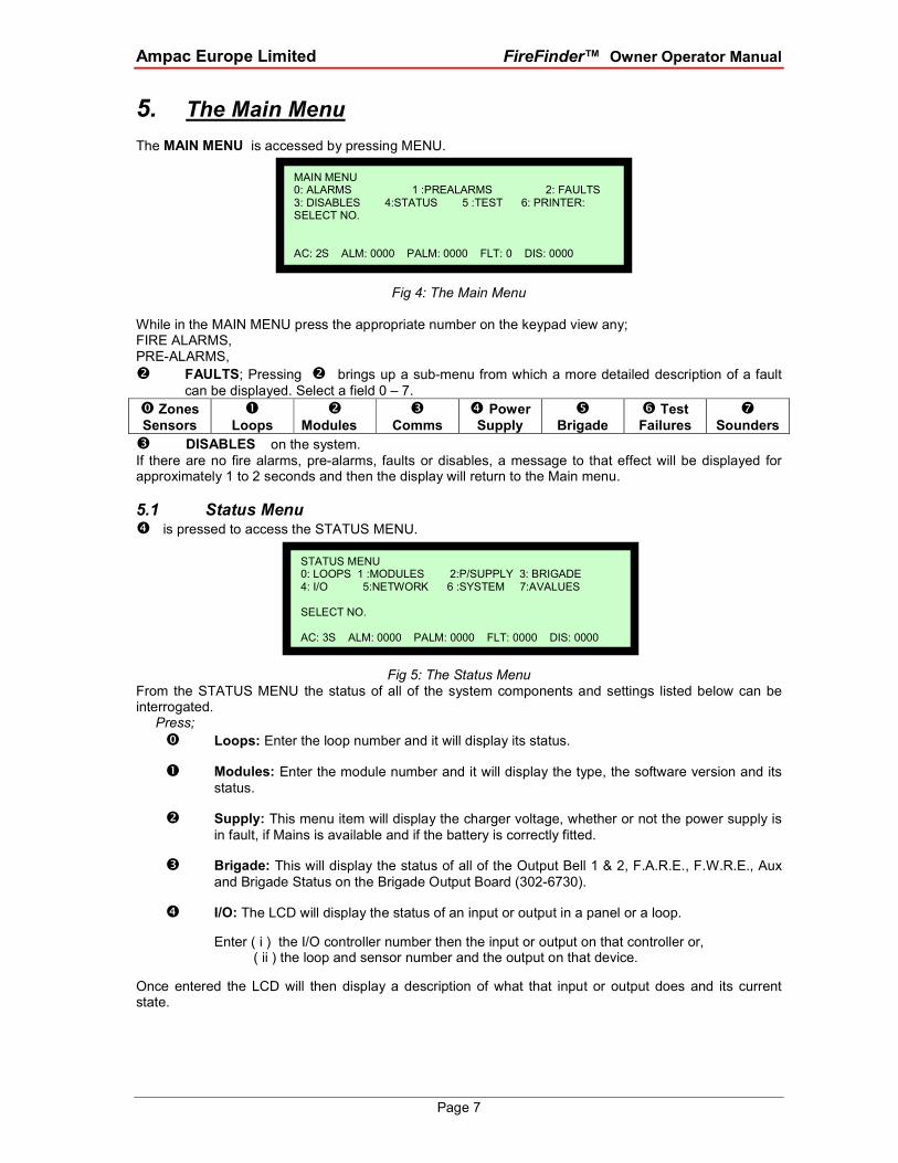
5.2 Testing Menu � is pressed to access the TESTING MENU. From here the following can be tested:
Fig 11: The Testing Menu Alarm Test
� Alarm tests either a selected zone or a sensor or a range of zones or sensors.
(This test will force a sensor to go to the Alarm State or a conventional zone to a simulated Alarm State) Fault Test
� Fault tests either a zone or a sensor or a range of zones or sensors.
(This test will force a sensor to go to the Fault State or a conventional zone to a simulated Fault State)
Once the above tests have been completed the TEST COMPLETE screen will appear. Each ALARM and FAULT that was detected can be viewed by scrolling through them using the NEXT and PREVIOUS buttons.
Lamp Test
� Will flash the LED’s in sequence on the front panel and illuminate the various segments on the LCD display.
5.3 Sounders Press
to select Sounders then � to enable / disable as required.
5.4 Printer Menu Press
to select the panel thermal printer ( if installed ) then � to force it to Go ON or OFF Line.
TESTING MENU 0: ALARM 1: FAULT 2: LAMP SELECT NO. AC:3S ALM: 0000 PALM: 0000 FLT: 0000 DIS: 0000
Loop 1 sensor 1 L1 S1 Z2 STAT: NORMAL AVALUE: 25 MODE: 0 I: 000 O:: 000 AC: 2S ALM: 000 PALM: 0000 FLT: 0000 DIS: 0000

Ampac Europe Limited FireFinder™ Owner Operator Manual
Page 10
6. Main Functions
Fig 12: The Level III Functions Menu
6.1 Setting the Function Date Facility
Select FUNCTION . A prompt will ask for a PASSWORD if the control panel is not currently active.
Using the keypad key in the PASSWORD and press ENTER .
Press
� to select the set DATE SCREEN. The prompt will ask for the date to be entered in this format,
DD/MM/YYYY ( EG 18/09/2001 ), key in and press ENTER . The screen will then return to the MAIN
FUNCTIONS MENU.
6.2 Setting the Function Time Facility Press
� then in the following format key in the time, HH:MM using the 24 hour mode. Press ENTER and
the screen will return to the MAIN FUNCTIONS MENU.
6.3 Setting the Function Daynight Facility Press
� The DAY-NIGHT SETTINGS screen will appear.
Press
� to enter the DAY ON time then ENTER and,
� to enter the NIGHT ON time then ENTER .
To enter this mode the function must be ENABLED, press � Re-pressing � will DISABLE
the DAYNIGHT function.
LEVEL III MAIN FUNCTIONS 0: DATE 1: TIME 2: DAY/NIGHT 3: LOGS 4: TESTS 5: I/O 6: PROG 7: P/WORD 8: LANGUAGE SELECT NO.
AC: 3S ALM: 0000 PALM: 0000 FLT: 0000 DIS: 0000

Ampac Europe Limited FireFinder™ Owner Operator Manual
Page 11
6.4 Function Logs Facility Press
� and the EVENT LOG MENU will appear.
The LOGS MENU functions allows the operator to select and view the events of all;
Press
� ALARMS
� FAULTS
� DISABLES
The date and time of the ALARM, FAULT or DISABLE as well as the device information will be displayed. This screen also allows the operator to select two other facilities;
Press
� PRINT ENTRY If a printer is installed pressing will print out the displayed information,
or
� SHOW OPTIONS by pressing
This screen allows the operator to view the Logs by pressing � to VIEW BY ENTRY NUMBER
or by pressing � to VIEW BY DATE. In each case the screen will ask for the appropriate
information ( ENTRY NUMBER or DATE ) to be entered before anything can be displayed.
6.5 The Function Test Facility Press � The resulting screen is the TESTING MENU and prompts the operator to select the type of test they wish to perform, � for the WALK test and � for the LOOP test.
Press � WALK TEST; again the operator will be prompted to select either a
ZONE ( press � ) or SENSOR ( press � ) TEST.
� ZONE WALK TEST MENU;
This screen requires the operator to select a Zone or number of Zones to be tested, that is enter the
Zone number and press ENTER or enter the Zone number press TO then the next highest Zone
number to be tested EG. 2 TO 7 then ENTER. The TEST MODE LED will be illuminated for the duration of the test and the test will run until the operator RESETS the system.
� SENSOR WALK TEST MENU
This screen requires the operator to select a Zone and then a Sensor or number of Sensors (
using the TO key ) to be tested then pressing ENTER to start the test.
The TEST MODE LED will be illuminated for the duration of the test and the test will run until the operator RESETS the system.
PREVIOUS NEXT���� Note: it is possible to scroll through the Logs by using

Ampac Europe Limited FireFinder™ Owner Operator Manual
Page 12
Press � LOOP TEST requires the operator to select a LOOP for DIAGNOSTIC TESTING
Entering the LOOP number and pressing ENTER will initiate the DIAGNOSTIC TEST.
���� Note: The LED’s on the Brigade Board will indicate which leg is being tested.
The tests displayed are; � TESTING SIDE A IDENTIFYING DEVICES on SIDE A, and
� TESTING SIDE B IDENTIFYING DEVICES on SIDE B.
Once the testing is completed the final screen will display the number of devices found and tested on the LOOP.
���� Note: If the data is not entered within 2 minutes the screen will time out and return to the DEFAULT
SCREEN.
6.6 Function Manual I/O Control Press
� to display the Manual I/O Control menu
Fig 13: The Manual I/O Control Menu MANUAL I/O CONTROL
Press
� Input Selected:
Press
� IN A PANEL: Enter the I/O Controller number then the input number , This will
display the description for the input and its current state, you can then turn the input on or off or remove manual control.
� ON A LOOP: Enter the loop number , the sensor number and the input
number. This will display the description for the input and its current state, you can
then turn the input on or off or remove manual control.
� Remove All Manual Input Control: Will remove all manual input control.
� Output Selected: Same sequences as above for inputs but
substitute outputs for Inputs.
� Remove All Manual Control Selected: Globally removes all manual control.
MANUAL I/O CONTROL 0: INPUT 1 :OUTPUT 2: REMOVE ALL MANUAL CONTROL SELECT NO. AC: 3S ALM: 0000 PALM: 0000 FLT: 0000 DIS: 0000

Ampac Europe Limited FireFinder™ Owner Operator Manual
Page 13
6.7 Function Programming Press to display the Programming Menu.
Fig 14: The Programming Menu
6.7.1 Conventional Zone Programming Press
� Zone:
Key in the zone number and enter or change the description ( DESC ) by pressing the numeric buttons multiple times to access characters while at the same time using
Fig 15: Zone Description & Type Programming
Fig 16: Brigade Options
ON SITE PROGRAMMING MENU 0: CONV ZONE 1 :DEVICE 2:INPUT 3: OUTPUT 4: PANEL BASED MCP SELECT NO. AC: 3S ALM: 0000 PALM: 0000 FLT: 0000 DIS: 0000
EDIT Zx DESC AND TYPE STRINGS DESC < ZONE > TYPE< ALPHA KEYS ARE ACTIVE AC: 3S ALM: 0000 PALM: 0000 FLT: 0000 DIS: 0000
buttons to move the flashing underline or cursor.
Press to move to the TYPE field or edit the information.
Press to move between fields use the reciprocal button
By going through all the fields a second screen can be accessed to show the Output options. Press to step through these fields
These keys are used to set the Y/N field, that is the selected Zone that will activate the Brigade options ALRM, bell etc. and Config.
EDIT ZX BRIGADE OPTIONS AND CONFIG ALRM: Y/N BELL: Y/N AUX: Y/N SPRK: Y/N AIF: Y/N ALARM LED: Y/N CONFIG: LATCHING Use < or > to change setting AC: 3S ALM: 0000 PALM: 0000 FLT: 0000 DIS: 0000

Ampac Europe Limited FireFinder™ Owner Operator Manual
Page 14
Fig 17: Zone Configuration Latching / Non-Latching
Configuration settings are latching, Non-Latching, AVF and Self Reset ( 0 to 99 seconds ).
After setting the Configuration the ZONE, I/O GROUPS are then programmed.
Fig 18: Zone I/O Groups
After scrolling through the groups and entering what I/O GROUPS will be turned on by WHAT MODULE
OR DEVICE IN A ZONE the operator is prompted to press ENTER to confirm the entries and / or
changes.
6.7.2 Device Programming � DEVICE:
Screen:
Enter the Loop and Sensor number then scroll through the following screens.
Press or Press
� to EDIT or � to DELETE
After scrolling through the groups a prompt requests the operator to press ENTER to confirm the
changes.
EDIT Z CONFIGURATION CONFIG: LATCHING Use < or > to change alarm setting AC: 3S ALM: 0000 PALM: 0000 FLT: 0000 DIS: 0000
EDIT Z I/O GROUPS GROUP1: GROUP2: GROUP3: GROUP4: GROUP5: GROUP6: Enter GROUP NO. AC: 3S ALM: 0000 PALM: 0000 FLT: 0000 DIS: 0000
Use these keys to MOVE between fields ie: DESC & TYPE and NEXT PARAMETER SETTING
Use these keys to EDIT and move through wording & numbering.
Use or to change the latching setting
1. EDIT LxSx DESCRIPTION AND TYPE STRING. After each step press eg: DESC DETECTOR 1
TYPE SMOKE
2. Allocate / Edit the Sensor to a Zone and set the device type eg: XP95 Photo, XP95 Heat etc.
3. Set /edit and displays the Output Configurations or options. eg: Latching, AVF, Non-latching etc
4. Set / edits and enables / disables the day/night settings.
5. Allocates / edits the Loop and Sensors Groups.

Ampac Europe Limited FireFinder™ Owner Operator Manual
Page 15
6.7.3 Input Programming Press
� INPUT: By following the screen prompts in the same way as above Edit or delete an INPUT in a panel or a loop.
Screen: PROGRAM MENU SELECTING AN INPUT
� IN A PANEL � ON A LOOP
i) PANEL, LOOP OR REMOVE i) LOOP
Select one of the above Select LOOP NO. then ENTER
ii) I/O MODULE ii) SENSOR
Select I/O MODULE NO. then ENTER Select SENSOR NO. then ENTER
iii) IINPUT iii) INPUT
Select I/P NO then ENTER Select INPUT NO. then ENTER key
iv) EDIT / DELETE DESC iv) EDIT LxSxI/Px DESC STRING
ALPHA KEYS ARE ACTIVE DESC
6.7.4 Output Programming Press
� OUTPUT: By following the screen prompts in the same as previously Add, Edit or
Delete an output in a panel or on a loop.
6.7.5 Watchdog
Press
� to view the number of resets and or press � to reset the Watchdog counter
6.8 Extra Devices Detected If Self Learn is enabled and FireFinder detects extra modules or devices, that is devices or modules that have been added or there has been a change of description or type, the
FireFinder LCD will indicate this by displaying the screen below.
Fig 19: Resolving Extra Modules And Devices
To resolve select FUNCTION, enter PASSWORD, press and the screen below will appear
Fig 20:Added Module Or Device
PROGRAMMING MENU 0: RESOLVE EXTRA MODULES AND DEVICES 1: ON SITE PROGRAMMING SELECT NO. AC: 3S ALM: 0000 PALM: 0000 FLT: 0000 DIS: 0000
FIREFINDER 26/9/2001 08:05:45 EXTRA DEVICES DETECTED GOTO PROGRAMMING MENU TO RESOLVE SYSTEM IS NOT NORMAL
AC: 3S ALM: 0000 PALM: 0000 FLT: 0000 DIS: 0000

Ampac Europe Limited FireFinder™ Owner Operator Manual
Page 16
Example: Entering � ( Entering � presents the PROGRAMMING MENU. ) Select the appropriate programming screen from those listed on the screen ( as seen below ) and select
enter to accept the changes or skip to resolve the changes manually.
Fig 21: Resolving Extra Modules Or Devices
6.9 Function Passwords Press
while in the Main Functions menu (if your password gives you access) to display the Password Menu.
Fig 22: The Password Menu
Press
� Add Password: Enter the new password, then press ENTER . The password is always a
4 digit number.
� Delete Password: Enter the password that you want to delete, then press ENTER.
� Delete All Passwords: This asks you to confirm that you want to delete all the
passwords. Press ENTER then ENTER again.
6.9.1 Forgotten Passwords If you have forgotten your password,
a. enter 9999 into the password field;
b. Take note of the 4 digit password button displayed on the screen;
c. contact the AMPAC head office and quote this number;
d. a temporary password will be issued to allow access to the level 3 functions
e. a new password can now be programmed.
Note:The temporary password will become invalid if 9999 is entered again or if the panel is re-powered.
6.10 The Function Language To select the LANGUAGE that is to be used on the screen select;
a. the FUNCTIONS screen;
b. then � for the LANGUAGE MENU.
c. Toggle the � key until the required language is displayed on the forth line of the screen,
eg. CURRENT LANGUAGE: ENGLISH Rev: 1 then
d. RESET to return to the DEFAULT MENU.
PASSWORD MENU 0: ADD PASSWORD 1 :DELETE PASSWORD 2: DELETE ALL PASSWORDS SELECT NO. AC: 4S ALM: 0000 PALM: 0000 FLT: 0000 DIS: 0000
0: ADD EXTRA MODULES 1: ADD EXTRA DEVICES 2: DEVICE TYPE MISMATCH 3: MODE MISMATCH SELECT NO. AC: 3S ALM: 000 PALM: 0000 FLT: 0000 DIS: 0000

Ampac Europe Limited FireFinder™ Owner Operator Manual
Page 17
7. Incoming Fire Alarm Signal Will operate the red common LED fire indicator
• Will display location of fire alarm origin on the LCD
• Will activate external alarm.
• Will activate the internal FACP buzzer. (optional)
• Will activate any ancillary equipment so programmed.
• Will abort any test in progress.
The LCD will always display the first fire alarm signal received in the top section of the LCD. The lower section of the LCD will also permanently display the most recent zone in alarm. Other essential fire alarm information and fault or disablement information is available via the previous and next keys. After 30 seconds if no key is pressed the top section of the display will revert to displaying the first zone in alarm. If there are any faults or fire alarms the LCD will display the device in question in the top screen, if
multiple detectors or zones are not in their normal state, the PREVIOUS
NEXT
buttons are used to scroll through them.
Fig 23: LCD Screen With 5 Devices In Alarm
If a fault or a fire alarm condition exists and the buzzer is sounding, press the
BUZZERSILENCE
to silence.
8. Accessing a Loop, Sensor or Zone LOOP OR SENSOR
1. From the default display, press LOOP 2. Enter the loop number you wish to interrogate then press SENSOR. 3. Press the button for the sensor number. 4. Press the TO button if you wish to access a range of sensors on the loop, 5. Press the DISPLAY button if you wish to display the status of a sensor, 6. Press the DEVICE DISABLE / ENABLE button if you wish to disable a sensor 7. Press the DEVICE DISABLE / ENABLE button again to enable a sensor.
Fig 24: LCD Screen With 5 Devices In Alarm ZONE
1. From the default display, press ZONE 2. Press the button for the zone number. 3. Press the TO button if you wish to access a range of zones, 4. Press the DISPLAY button if you wish to display the status of a zone, 5. Press the DEVICE DISABLE / ENABLE button if you wish to disable a zone 6. Press the DEVICE DISABLE / ENABLE button again to enable a sensor.
DETECTOR 1 SMOKE L1 S1 Z17 ALARM 17/9/2002 15:12: 10 SENSOR ALARMS 1 OF 5 ****************CURRENT ALARM***************** DETECTOR 5 L1 S5 Z17 ALARM17/9/2001 15:12:10 AC: 1 ALM: 5 PALM: 0 FLT: 0 DIS: 0
DEVICEDISABLE/ENABLE
LOOP 1ABC SENSOR JKL
4
TUV7TO
DISPLAY
For Multiple Devices

Ampac Europe Limited FireFinder™ Owner Operator Manual
Page 18
9. Certification Information
The FireFinder™ is designed by and is manufactured by:
AMPAC TECHNOLOGIES PTY LTD
97 Walters Drive
Osborne Park 6017
Western Australia
PH: 61-8-9242 3333
FAX: 61-8-9242 3334
Manufactured to: EN 54 Parts 2 & 4
Certificate of Compliance Number:
Model Number:
Equipment Serial Number:
Date of Manufacture:

Ampac Europe Limited FireFinder™ Owner Operator Manual
Page 19
10. Glossary of Terms ACF : ANCILLARY CONTROL FACILITY
ACKD : ACKNOWLEDGED
AHU : AIR HANDLING UNIT
ALM : ALARM
AVF : ALARM VERIFICATION FACILITY
AZF : ALARM ZONE FACILITY
AZC : ALARM ZONE CIRCUIT
C : RELAY COMMON CONTACT (WIPER)
CN : CONNECTOR
CPU : COMMON PROCESSOR UNIT
DGP : DATA GATHERING POINT
EARTH : BUILDING EARTH
EOL : END OF LINE
FACP : FIRE ALARM CONTROL PANEL
FDS : FIRE DETECTION SYSTEM
FLT : FAULT
GND : GROUND (0 VOLTS) NOT EARTH
I/O : INPUT/OUTPUT
LCD : LIQUID CRYSTAL DISPLAY
MAF : MASTER ALARM FACILITY
MCP : MANUAL CALL POINT
MOV : METAL OXIDE VARISTOR (TRANSIENT PROTECTION)
NIC : NETWORK INTERFACE CARD
N/C : NORMALLY CLOSED RELAY CONTACTS
N/O : NORMALLY OPEN RELAY CONTACTS
PCB : PRINTED CIRCUIT BOARDS
P/S : POWER SUPPLY
PSM : POWER SUPPLY MODULE
REM : REMOTE
SPOT : SINGLE PERSON OPERATING TEST
TB : TERMINAL BLOCK
VDC : DIRECT CURRENT VOLTS

Ampac Europe Limited FireFinder™ Owner Operator Manual
Page 20
11. Definitions Addressable system - a fire alarm and detection system that contains addressable alarm zone facilities or addressable control devices.
Alarm Verification Facility (AVF) - that part of the FACP, which provides an automatic resetting function for spurious alarm signals so that they will not initiate master alarm facility (MAF), or ACF functions
inadvertently. Using the configuration manager prior to downloading to the FireFinder™ sets this option
Alarm zone - the specific portion of a building or complex identified by a particular alarm zone facility.
Alarm Zone Circuit (AZC) - the link or path that carries signals from an actuating device(s) to an alarm zone facility(s).
Alarm Zone Facility (AZF) - that part of the control and indicating equipment that registers and indicates signals (alarm and fault) received from its alarm zone circuit. It also transmits appropriate signals to other control and indicating facilities.
Ancillary Control Facility (ACF) - that portion of the control and indicating equipment that on receipt of a signal initiates predetermined actions in external ancillary devices.
Ancillary equipment - remote equipment connected to FACP.
Ancillary relay - relay within FACP to operate ancillary equipment.
Ancillary output - output for driving ancillary equipment.
Conventional System - is a fire detection system using a dedicated circuit for each alarm zone.
Distributed system - a fire alarm and detection system where sections of the control and indicating equipment are remotely located from the fire indicator panel or where sub-indicator panel(s) communicate with a main fire indicator panel.
Factory connections - are connections made during manufacture and should not require any field alterations.
Field connections - are connections made to FACP or ancillary equipment at the project during installation.
Fire alarm system - an arrangement of components and apparatus for giving an audible, visible, or other perceptible alarm of fire, and which may also initiate other action.
Fire detection system - an arrangement of detectors and control and indicating equipment employed for automatically detecting fire and initiating other action as arranged.
Fire Alarm Control Panel (FACP) - a panel on which is mounted an indicator or indicators together with associated equipment for the fire alarm or sprinkler system.
Indicating equipment - the part of a fire detection and or alarm system, which provides indication of any warning signals (alarm and fault), received by the control equipment.
Interface - The interconnection between equipment that permits the transfer of data.
Main equipment - equipment essential to the operation of the system including, control equipment, amplification equipment and power supply modules.
Master Alarm Facility (MAF) - that part of the control and indicating equipment which receives alarm and fault signals from any alarm zone facility and initiates the common signal (alarm and/or fault) for transmission to the fire control station where appropriate. Bells and other ancillary functions may be initiated from this facility.
Power Supply - that portion of the Fire alarm Control Panel (FACP) which supplies all voltages necessary for operation of the FACP.

Ampac Europe Limited FireFinder™ Owner Operator Manual
Page 21
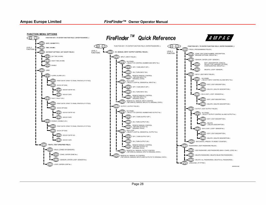
12. Quick Reference Guides The following guides;
1. Prompt / assist an experienced operator to move through the Menu and Function facilities of the FACP without having to consult the main body this manual; and
2. provide a proforma for Brigade response to an alarm
Quick ReferenceMAIN MENU OPTIONS
MENU KEY / FUNCTION KEY ( TO ENTER MENU / TO FUNCTION MENU )
ALARMS ( DISPLAY ALARMS )
PREALARMS ( DISPLAY PRE-ALARMS )
FAULTS ( DISPLAY FAULTS OF SELECTED FIELDS )
ZONES/SENSORS
LOOPS
MODULES
P/SUPPLY
BRIGADE
TEST FAILURES
DISABLES ( DISPLAY ALL SYSTEM DISABLES)
STATUS (DISPLAY STATUS OF SELECTED FIELDS)
( FAULT FIELDS )
( STATUS FIELDS )
LOOPS ( LOOP / SENSOR No )
MODULES ( MODULE No )
P/SUPPLY
BRIGADE (BRIGADE O/PS)
NETWORK
TESTING ( TESTING THE SELECTED TEST FIELDS )
ALARM (TEST ALARM FIELDS )
OUTPUTS (OUTPUT No)
INPUT (INPUT No)
FAULT ( TEST FAULT FIELDS )
LAMP
( TEST FIELDS )
ZONE ( ZONE No )
SENSOR ( LOOP/SENSOR No )
I/O
NETWORK POINTS
REMOTE SLAVE MODULES
REMOTE EXT LED MIMIC MODULES
SYSTEM
AVALUES ( ANALOGUE VALUE OF DET )
ZONE ( ZONE No )
SENSOR ( LOOP/SENSOR No )
MENU KEY / FUNCTION KEY ( TO ENTER MENU / TO FUNCTION MENU )
SPACE0
DEF2
MENU
ABC1
SPACE0
ABC1
DEF2
GHI3
JKL4
MNO5
ABC1
DEF2
GHI3
JKL4
MNO5
SPACE0
SPACE0
SPACE0
SPACE0
GHI3
JKL4
MNO5
DEF2
PQRS6
ABC1
ABC1
ABC1
FUNCTION
SPACE0
ABC1
DEF2
TUV7
PQRS6
SPACE0
ABC1
MENU FUNCTION
PRINTERTUV7
FireFinderTM
SOUNDERS
COMMS
PQRS6
SOUNDERTUV7
Ampac Europe Limited FireFinder™ Owner Operator Manual
Page 28
FireFinderTM
Quick ReferenceFUNCTION KEY ( TO ENTER FUNCTION FIELD ( ENTER PASSWORD ) )
PROG ( PROGRAMMING FEILDS )
EDIT ( EDIT DESCRIPTION )
DELETE ( LOOP / SENSOR )
IN A PANEL ( SELECT INPUT CONTROL No AND INPUT No )
EDIT ( EDIT DESCRIPTION )
ZONE ( EDIT ZONE NUMBER, DESCRIPTION, BRIGADE OPTIONS, GROUP No )
INPUT ( EDIT INPUT FIELDS )
EDIT ( DESCRIPTION, ZONE No, DEVICE TYPE, BRIGADE OPTIONS, CONFIGURATION, GROUP No )
DELETE ( DELETE DESCRIPTION )
ON A LOOP ( LOOP / SENSOR No )
SENSOR ( ENTER LOOP / SENSOR )
DELETE ( DELETE DESCRIPTION )
EDIT ( EDIT DESCRIPTION )
IN A PANEL ( SELECT OUTPUT CONTROL No AND OUTPUT No )
EDIT ( EDIT DESCRIPTION )
OUTPUT ( EDIT OUTPUT FIELDS )
DELETE ( DELETE DESCRIPTION )
ON A LOOP ( LOOP / SENSOR No )
DELETE ( DELETE DESCRIPTION )
PASSWORDS ( EDIT PASSWORD FIELDS )
ADD PASSWORD ( ADD PASSWORD (MAX 4 CHAR), LEVEL No )
DELETE PASSWORD ( DELETE SELECTED PASSWORD )
DELETE ALL PASSWORDS ( DELETE ALL PASSWORDS )
LEVEL 3FUNCTION
FUNCTION KEY ( TO ENTER FUNCTION FIELD ( ENTER PASSWORD ) )
I/O ( MANUAL INPUT /OUTPUT CONTROL FIELDS )
OFF ( TURN INPUT OFF )
ON ( TURN INPUT ON )
ON A LOOP ( SELECT LOOP No, SENSOR No, INPUT No )
REMOVE ALL MANUAL INPUT CONTROL( RETURN ALL MANUAL INPUTS TO ORIGINAL STATE )
INPUT ( INPUT FIELDS )
IN A PANEL ( SELECT I/O CONTROL NUMBER AND INPUT No )
REMOVE MANUAL CONTROL ( RETURN INPUT TO ORIGINAL STATE)
OFF ( TURN INPUT OFF )
ON ( TURN INPUT ON )
REMOVE MANUAL CONTROL ( RETURN INPUT TO ORIGINAL STATE)
OFF ( TURN OUTPUT OFF )
ON ( TURN OUTPUT ON )
ON A LOOP ( SELECT LOOP No, SENSOR No, OUTPUT No )
REMOVE ALL MANUAL OUTPUT CONTROL( RETURN ALL MANUAL O/PS TO ORIGINAL STATE )
OUTPUT ( OUTPUT FIELDS )
IN A PANEL ( SELECT I/O CONTROL NUMBER AND OUTPUT No )
REMOVE MANUAL CONTROL ( RETURN OUTPUT TO ORIGINAL STATE)
OFF ( TURN OUTPUT OFF )
ON ( TURN OUTPUT ON )
REMOVE MANUAL CONTROL ( RETURN OUTPUT TO ORIGINAL STATE)
REMOVE ALL MANUAL I/O CONTROL( RETURN ALL MANUAL INPUTS AND OUTPUTS TO ORIGINAL STATE )
LEVEL 3FUNCTIONS
FUNCTION MENU OPTIONS
FUNCTION KEY ( TO ENTER FUNCTION FIELD ( ENTER PASSWORD ) )
DATE ( DD/MM/YYYY )
TIME ( HH:MM )
DAY/NIGHT SETTINGS ( SET ON/OFF FIELDS )
DAY TIME (HH:MM)
ENABLE
LOGS
LEVEL 3FUNCTIONS
NIGHT TIME (HH:MM)
ALARM ( ALARM LOG )
SHOW OPTIONS
VIEW BY ENTRY NO.
VIEW BY DATE
PRINT ENTRY (PRINT TO PANEL PRINTER (IF FITTED))
FAULT ( FAULT LOG )
SHOW OPTIONS
VIEW BY ENTRY NO.
VIEW BY DATE
PRINT ENTRY (PRINT TO PANEL PRINTER (IF FITTED))
DISABLE ( DISABLE LOG )
SHOW OPTIONS
VIEW BY ENTRY NO.
VIEW BY DATE
PRINT ENTRY (PRINT TO PANEL PRINTER (IF FITTED))
WALK ( ZONES OR SENSORS )
TESTS ( TEST SPECIFIED FIELD )
ZONE ( ENTER ZONE No )
SENSOR ( ENTER LOOP / SENSOR No )
LOOP ( ENTER LOOP No )
QUICK22.CAD
PQRS6
SPACE0
ABC1
SPACE0
SPACE0
ABC1
DEF2
ABC1
ABC1
SPACE0
ABC1
SPACE0
ABC1
SPACE0
GHI3
ABC1
SPACE0
ABC1
SPACE0
TUV7
SPACE0
ABC1
DEF2
MENU FUNCTION
MNO5
SPACE0
SPACE0
ABC1
DEF2
ABC1
SPACE0
SPACE0
ABC1
DEF2
SPACE0
SPACE0
ABC1
DEF2
ABC1
SPACE0
ABC1
DEF2
ABC1
DEF2
DEF2
DEF2
MENU FUNCTION
SPACE0
DEF2
ABC1
SPACE0
ABC1
GHI3
MENU FUNCTION
2DEF
SPACE0
SPACE0
ABC1
SPACE0
ABC1
SPACE0
ABC1
SPACE0
ABC1
DEF2
SPACE0
ABC1
SPACE0
ABC1
1ABC
JKL4
SPACE0
SPACE0
ABC1
ABC1
WATCHDOG ( PRESS 0 TO RESET COUNTER )JKL4
LANGUAGE ( IF FITTED )WXYZ8
Ampac Europe Limited FireFinder™ Owner Operator Manual
Page 29
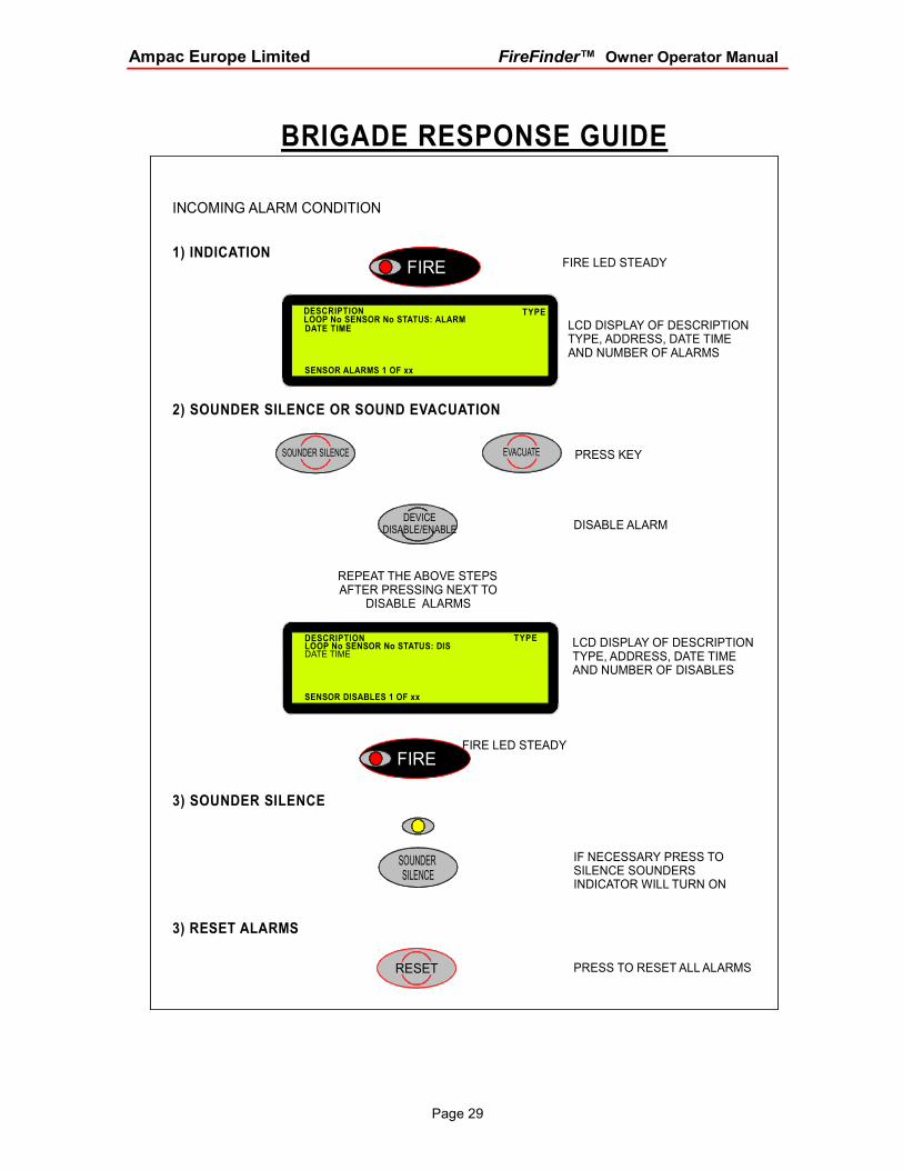
BRIGADE RESPONSE GUIDE
INCOMING ALARM CONDITION
1) INDICATIONFIRE LED STEADY
LCD DISPLAY OF DESCRIPTIONTYPE, ADDRESS, DATE TIME AND NUMBER OF ALARMS
2) SOUNDER SILENCE OR SOUND EVACUATION
PRESS KEY
DISABLE ALARM
REPEAT THE ABOVE STEPSAFTER PRESSING NEXT TO
DISABLE ALARMS
LCD DISPLAY OF DESCRIPTIONTYPE, ADDRESS, DATE TIME AND NUMBER OF DISABLES
3) SOUNDER SILENCE
FIRE LED STEADY
IF NECESSARY PRESS TO SILENCE SOUNDERSINDICATOR WILL TURN ON
3) RESET ALARMS
PRESS TO RESET ALL ALARMS
FIRE
SOUNDER SILENCE
RESET
DEVICEDISABLE/ENABLE
EVACUATESOUNDER SILENCE
FIRE
DESCRIPTION
DATE TIMELOOP No SENSOR No STATUS: ALARM
SENSOR ALARMS 1 OF xx
TYPE
LOOP No SENSOR No STATUS: DISDESCRIPTION
DATE TIME
SENSOR DISABLES 1 OF xx
TYPE


AMPAC EUROPE LIMITED UNIT 1 NORDEN COURT ALAN RAMSBOTTOM WAY
GREAT HARWOOD BLACKBURN BB6 7UR
ENGLAND
PH: 44 (0) 1254 880 201
FAX: 44 (0) 1254 880 202 Email: [email protected] Website: www.ampac.net
AMPAC TECHNOLOGIES PTY LTD HEAD OFFICE
NOTE: Due to Ampac’s commitment to continuous improvement specifications may change without notice.
UNCONTROLLED DOCUMENT