Embed Size (px)
Citation preview

RS-330/332 Multipurpose Gamma-Ray
Spectrometer System
Operator Manual
Revision 2.00 – May 2017
Firmware Version 0.90
Part Number D-1036
RS-330 RS-332
D-1036 REV 02.00 Status: RELEASED printed 16/05/2017 9:45:26 AM by Radiation Solutions Inc.

D-1036 REV 02.00 Status: RELEASED printed 16/05/2017 9:45:26 AM by Radiation Solutions Inc.

RS-330/332 Operators’ Manual – Revision 2.00
Radiation Solutions Inc – Proprietary Page iii Revision Date: May 16, 2017
Revision History
Date Revision ECO # Description
January 2015 00.00 NA Preliminary (DRAFT)
February 2015 00.01 NA Update front cover
March 2015 00.02 NA Update with comments by Ron Martin
April 2, 2015 01.00 54 Initial Release
April 15, 2015 01.01 56 Update Product Screen
April 28,2015 01.02 60 Update Firmware Version
May 25, 2015 01.03 65 Update for Record and Save Notes
June 12, 2015 01.04 70 Update for device FW and changes to Geoview
Sept 29, 2015 01.05 79 Update – technician comments - new FW v0.38
Nov 06, 2015 01.06 86 Change company address
Apr 06, 2016 01.07 102 Update for new software GeoView v04.92
Sept 12,2016 01.08 115 Update for device FW v0.68 and GeoView v05.00
Apr 13, 2017 01.09 131 Change Product name from RS-330S to RS-332, Update the device for FW v0.79 and replace GeoView with RSAnalyst v 2.1.19, Add Section for Core Sampling
May 05, 2017 01.10 135 Update the device for FW v0.88, and RSAnalyst v2.1.22
May 16, 2017 02.00 136 Update the device for FW v0.90, and RSAnalyst v2.1.23
Certificate of Origin This is to certify that GEORADIS s.r.o., Novomoravanska 41 is the manufacturer of the RS-330x series Radiation Detectors. All instruments are designed, manufactured and assembled in Czech Republic. PRODUCT STATEMENT RSI is responsible for Sales/Marketing and Customer Support for this product in North, Central and South America, China, Australia/NZ and most other areas of the world excluding EUROPE and JAPAN.
ADVISORY
NOTES:
1. Users are advised that the manual and software supplied with the instrument is current when manufactured, however, a program of continuous improvement means that many new features are added and old ones improved upon. Users are advised to contact RSI directly for new releases including manuals and software. The most current version of the manual is provided in electronic format on the Product Support CD supplied with the instrument. Please refer to the electronic version of the manual for the most accurate interpretation.
2. USERS ARE REMINDED THAT THE RS-33X series, IN COMMON WITH OTHER SIMILAR INSTRUMENTS, USES A Sodium-Iodide or BGO (BISMUTH GERMANATE OXIDE) CRYSTAL AS THE DETECTOR. THIS CRYSTAL IS FRAGILE AND EVEN THOUGH THE UNIT HAS BEEN RUGGEDISED FOR FIELD USE, GREAT CARE SHOULD BE TAKEN TO AVOID ABUSING THE INSTRUMENT AS THE VERY EXPENSIVE CRYSTAL IS NOT COVERED UNDER WARRANTY.
D-1036 REV 02.00 Status: RELEASED printed 16/05/2017 9:45:26 AM by Radiation Solutions Inc.

RS-330/332 Operators’ Manual – Revision 2.00
Radiation Solutions Inc – Proprietary Page iv Revision Date: May 16, 2017
CONFIDENTIAL DISCLOSURE
USERS ARE HEREBY NOTIFIED THAT THIS MANUAL CONTAINS TECHNICAL INFORMATION OF A PROPRIETARY NATURE. THIS INFORMATION IS NECESSARY FOR TECHNICALLY KNOWLEDGEABLE USERS TO UNDERSTAND SYSTEM OPERATION AND TO SATISFY THEMSELVES THAT THE SYSTEM IS PERFORMING CORRECTLY. RADIATION SOLUTIONS INC ACCEPTS THAT IT IS THE RIGHT OF SUCH USERS TO BE PRIVY TO THIS INFORMATION. HOWEVER THIS DOCUMENTATION IS PROVIDED SOLELY FOR THE BENEFIT OF OWNERS OF THE RS-330/332 MULTIPURPOSE GAMMA-RAY SPECTROMETER SYSTEM AND DISSEMINATION OF THE DETAILED TECHNICAL INFORMATION PROVIDED MAY BE CONSIDERED AS LEGALLY CONTRAVENING THE NORMAL SUPPLIER/CUSTOMER RELATIONSHIP. UNAUTHORIZED RELEASE OF DETAILED TECHNICAL INFORMATION TO A THIRD PARTY WILL BE CONSIDERED AS A CONTRAVENTION OF USER AGREEMENTS.
Manufactured by Radiation Solutions Inc, 5875 Whittle Road, Mississauga, Ontario, Canada, L4Z 2H4
D-1036 REV 02.00 Status: RELEASED printed 16/05/2017 9:45:26 AM by Radiation Solutions Inc.

RS-330/332 Operators’ Manual – Revision 2.00
Radiation Solutions Inc – Proprietary Page v Revision Date: May 16, 2017
Table of Contents
1.0 INTRODUCTION ................................................................................................................ 1
1.1 FEATURES and SPECIFICATIONS ......................................................................................... 2 1.2 GENERAL ................................................................................................................................. 3
1.2.1 JOYSTICK OPERATION: ..................................................................................................... 4
2.0 SYSTEM OPERATION ....................................................................................................... 5
2.1 OVERVIEW ............................................................................................................................... 5 2.2 BATTERY .................................................................................................................................. 5
2.2.1 Battery Operation ................................................................................................................. 5 2.2.2 Battery Charging ................................................................................................................... 6
2.3 POWER DEVICE ...................................................................................................................... 6 2.3.1 Power Device (ON) ............................................................................................................... 6 2.3.2 Shutdown Device (OFF) ....................................................................................................... 6
2.4 DISPLAY ................................................................................................................................... 7 2.5 EXTERNAL CONNECTIONS .................................................................................................... 7 2.6 CONNECTIVITY ........................................................................................................................ 7
3.0 SURVEY ............................................................................................................................. 9
3.1 SURVEY MODE ........................................................................................................................ 9 3.2 AUDIO ..................................................................................................................................... 10 3.3 MENU ...................................................................................................................................... 10
3.3.1 Start Record ........................................................................................................................ 11 3.3.1.1 Store Note / Record Note ................................................................................ 11
3.3.2 Pause .................................................................................................................................. 12 3.3.3 Reacquire BG ..................................................................................................................... 12 3.3.4 Onfly Assay Results ........................................................................................................... 13
4.0 ASSAY .............................................................................................................................. 15
4.1 STABILIZATION ...................................................................................................................... 15 4.2 ASSAY MODE ......................................................................................................................... 16
4.2.1 Assay Results Screen ........................................................................................................ 16 4.2.2 Spectrum Display ............................................................................................................... 17 4.2.3 Core Method - Sampling ..................................................................................................... 18
5.0 IDENTIFY .......................................................................................................................... 21
5.1 IDENTIFY MODE .................................................................................................................... 21 5.1.1 Identify Menu ...................................................................................................................... 21 5.1.2 Identify – Graphic Menu ..................................................................................................... 22 5.1.3 Exploring the Spectrum ...................................................................................................... 22
6.0 DATA STORAGE and PC CONNECTIONS .................................................................... 25
6.1 DATA STORAGE .................................................................................................................... 25 6.1.1 Identify Log ......................................................................................................................... 26 6.1.2 Assay Log ........................................................................................................................... 26 6.1.3 Survey Log .......................................................................................................................... 27 6.1.4 Stabilization Log ................................................................................................................. 27 6.1.5 Calibration Log.................................................................................................................... 28 6.1.6 System Log ......................................................................................................................... 28
6.2 PC Software Download ........................................................................................................... 28 6.3 Install RSAnalyst ..................................................................................................................... 28 6.4 Startup RSAnalyst ................................................................................................................... 29
D-1036 REV 02.00 Status: RELEASED printed 16/05/2017 9:45:26 AM by Radiation Solutions Inc.

RS-330/332 Operators’ Manual – Revision 2.00
Radiation Solutions Inc – Proprietary Page vi Revision Date: May 16, 2017
6.4.1 Connect Device .................................................................................................................. 30
7.0 ALARMS ........................................................................................................................... 31
7.1 GAMMA ALARM ..................................................................................................................... 31 7.2 DOSE RATE ALARM .............................................................................................................. 32 7.3 DOSE ALARM ......................................................................................................................... 32
Appendix A TECHNICAL DATA ............................................................................................. 35
Appendix B QUICK START GUIDE ....................................................................................... 37
B.1 QUICK-OVERVIEW .................................................................................................................. 37 B.2 PC PROGRAMS ....................................................................................................................... 37 B.3 RECOMMENDED START ........................................................................................................ 37
Appendix Z WARRANTY ....................................................................................................... 39
System Requirements:
Hardware:
Gadget straps for carrying.(optional)
Car power outlet adapter (optional)
USB PC cable with mini USB connector for device
Power cable (Standard U.S. and European)
Software:
RSAnalyst v2.1.23
NOTE: Refer to the RSAnalyst User Manual (D-1180) for information concerning the operation and use of the RSAnalyst software.
D-1036 REV 02.00 Status: RELEASED printed 16/05/2017 9:45:26 AM by Radiation Solutions Inc.

RS-330/332 Operators’ Manual – Revision 2.00 INTRODUCTION
Radiation Solutions Inc – Proprietary Page 1 Revision Date: May 16, 2017
1.0 INTRODUCTION
The RS-330/332 Multipurpose Gamma-Ray Spectrometer System is the new state-of-the art in portable hand-held radiation survey instruments for high sensitivity assay applications. It offers an integrated design with full weather protection, large detector, easy to use and high sensitivity. It was designed as a multipurpose instrument to be usable in outdoor as well as in laboratory conditions.
There are 3 models available:
i. RS-330 – this is the base model and has a 3”x3” (21ci – 0.35L) Sodium-Iodide (NaI) detector
ii. RS-332 – a special model with a 2”x2” (6.3ci - 0.1L) Bismuth Germinate Oxide (BGO) detector
with an internal collimator
The figure below shows the size difference between the RS-330, and the RS-332.
RS-330 RS-332
D-1036 REV 02.00 Status: RELEASED printed 16/05/2017 9:45:26 AM by Radiation Solutions Inc.

RS-330/332 Operators’ Manual – Revision 2.00 INTRODUCTION
Radiation Solutions Inc – Proprietary Page 2 Revision Date: May 16, 2017
1.1 FEATURES and SPECIFICATIONS
- RS-330 – 3” x 3” (21ci 0.35L) Sodium-Iodide (NaI) detector provides high sensitivity performance due to the large crystal. Energy response is from 15keV - 3000keV.
- RS-332 – a special model with a 2” x 2” (6.3ci - 0.1L) Bismuth Germinate Oxide (BGO) detector with an internal collimator for special applications. Energy response is from 30keV - 3000keV.
- Sensitivities (1 MBq Cs-137 @ 1m): RS-330 = 386 cps, RS-332 = 160 cps
- Large Graphic Color Transflective LCD display 3.5” (90mm) diagonal and 360 x 240 pixels which ensure excellent readability in any outdoor conditions.
- Gyro stabilized screen
- Automatic light sensor that changes the standard Color screen to a Monochrome screen at higher light levels to permit easy readability even in strong sunlight
- Simple operation with a five-position navigation joystick with illuminated buttons
- Memory capacity – can store 8Gb (approximately 2000 samples) of spectra, assay results, GPS coordinates and voice recordings.
- USB and WiFi connection
- Integrated GPS.
- Integrated microphone for voice recording
- Internal rechargeable Li-ion battery module.
- Typical 10+ hour battery life at 20 0C.
- Size – RS-330 - Diameter = max 4.9” (124.5mm) – Height = 21.2” (538.5mm)
- Size – RS-332 - Diameter = max 4.9” (124.5mm) – Height = 18.1” (459.7mm)
- Weight – RS-330 - 4 kg, RS-332 = 8 kg
- Operational Temperature range -10 to +50 0C (limited by the display readability).
- IP65 weatherproofing – short term water immersion and fully dust protected.
- Strong aluminum casting construction, integrated detector, rubber shock absorber and thermal isolation.
- Well balanced, easy to hold and designed for easy operation in field conditions.
- New design state-of-the art electronics with advanced CPU capability with a fully digital spectrometer design
- Unique spectral analyze method, calibrated for different geometries and application. Measuring methods and Calibration are User Programmable.
- Energy compensated dose rate measurement.
- Automatic energy calibration based on natural background radiation.
No external radioactive sources required for stabilization. NOTE: The following acronyms are used for the remainder of this manual;
Sodium Iodide (NaI) detector
Bismuth Germinate Oxide (BGO) detector
D-1036 REV 02.00 Status: RELEASED printed 16/05/2017 9:45:26 AM by Radiation Solutions Inc.

RS-330/332 Operators’ Manual – Revision 2.00 INTRODUCTION
Radiation Solutions Inc – Proprietary Page 3 Revision Date: May 16, 2017
1.2 GENERAL
The RS-330 is designed as a portable handheld instrument. The design incorporates specifications for indoor as well as for outdoor applications in a wide range of temperature and humidity conditions. The RS-330 consists of a single body intended to be used in the vertical position (standing up) detector. The small diameter of the instrument allows the instrument to be easily placed in boreholes or tight shielding.
The instrument is self-contained so there are no additional devices required for its full functionality.
The upper (gray) section contains the operating electronics, the display and controls.
The lower (red) section of the instrument contains the detector Crystal assembly with internal temperature and shock protection.
The bottom of the instrument is protected with a rubber boot. The boot is removable to permit bottom access but is fully weatherproof.
The battery is mounted between these sections.
A loudspeaker is installed at the rear of the unit behind the perforated grill as shown by this picture.
The “black” section below the loudspeaker is a rubber weather cover that is opened to give access to the battery Charger and USB connection.
Users must only use the supplied USB and Charger cables supplied with the unit or the warranty may be voided. The top panel consists of a large display, a joystick (4 arrows + enter) and input jacks for microphone (MIC) and light sensor (SENS). A gray plastic lid under the handle hides the GPS the WiFi antenna is located below the display.
The joystick is made of five separate buttons. All buttons are protected with transparent rubber cover and illuminate (for scrolling) when user choices are required.
The instrument can be cleaned or decontaminated at any time with soapy water or ethyl/ isopropyl alcohol.
NOTE: USERS ARE REMINDED THAT THE RS-330 SERIES OF INSTRUMENTS, IN COMMON WITH OTHER SIMILAR INSTRUMENTS, USES A Sodium-Iodide OR BGO CRYSTAL AS THE DETECTOR. THIS CRYSTAL IS FRAGILE AND EVEN THOUGH THE UNIT HAS BEEN RUGGEDIZED FOR FIELD USE GREAT CARE SHOULD BE TAKEN TO AVOID ABUSING THE INSTRUMENT AS THE VERY EXPENSIVE CRYSTAL IS NOT COVERED UNDER WARRANTY.
D-1036 REV 02.00 Status: RELEASED printed 16/05/2017 9:45:26 AM by Radiation Solutions Inc.
RS-330/332 Operators’ Manual – Revision 2.00 INTRODUCTION
Radiation Solutions Inc – Proprietary Page 4 Revision Date: May 16, 2017
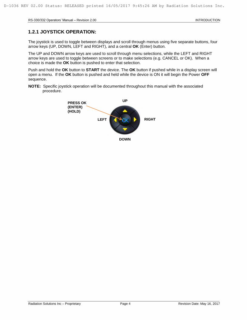
1.2.1 JOYSTICK OPERATION:
The joystick is used to toggle between displays and scroll through menus using five separate buttons, four arrow keys (UP, DOWN, LEFT and RIGHT), and a central OK (Enter) button.
The UP and DOWN arrow keys are used to scroll through menu selections, while the LEFT and RIGHT arrow keys are used to toggle between screens or to make selections (e.g. CANCEL or OK). When a choice is made the OK button is pushed to enter that selection.
Push and hold the OK button to START the device. The OK button if pushed while in a display screen will open a menu. If the OK button is pushed and held while the device is ON it will begin the Power OFF sequence.
NOTE: Specific joystick operation will be documented throughout this manual with the associated procedure.
RIGHT LEFT
PRESS OK (ENTER)
(HOLD)
DOWN
UP
D-1036 REV 02.00 Status: RELEASED printed 16/05/2017 9:45:26 AM by Radiation Solutions Inc.
RS-330/332 Operators’ Manual – Revision 2.00 SYSTEM OPERATION
Radiation Solutions Inc – Proprietary Page 5 Revision Date: May 16, 2017
2.0 SYSTEM OPERATION
2.1 OVERVIEW
This document only gives the practical information required by a Field Operator to use the RS-330 unit, A Reference Manual; Part # D-1037 is available to technicians needing information concerning the Parameter Settings and Calibration of the device.
NOTE: THE UNIT WHEN POWERED ON FIRST GOES INTO THE SURVEY MODE AS THIS IS NORMALLY WHERE THE OPERATOR WANTS TO START. HOWEVER FOR THE PURPOSE OF THIS MANUAL, ONLY SECTIONS PERTAINING TO THE OPERATOR WILL BE EXPLAINED – REFER TO THE REFERENCE MANUAL PN D-1037 FOR
PARAMETER SETTINGS, CALIBRATION AND DETAILED FUNCTION INFORMATION.
2.2 BATTERY
The RS-330 is powered from an internal Li-ion battery pack. Li-Ion batteries offer the best power per unit volume of any commercially available batteries but they are prone to damage if misused. To prevent these issues the pack is NOT USER replaceable and must be changed by trained personnel. For added protection only batteries with built-in protection are used and battery charging/discharging is automatically controlled.
Although the most critical conditions are automatically supervised by the systems’ internal computer, the user is requested to ensure that these guidelines are followed:
- Never charge the unit when the temperature of the batteries drops below 0 degree Celsius, best charging conditions are around 20 degrees Celsius.
- Do not store the unit with a fully discharged battery – charge before storing for more than 1 week.
- Pay attention to warning messages on the units display – if any
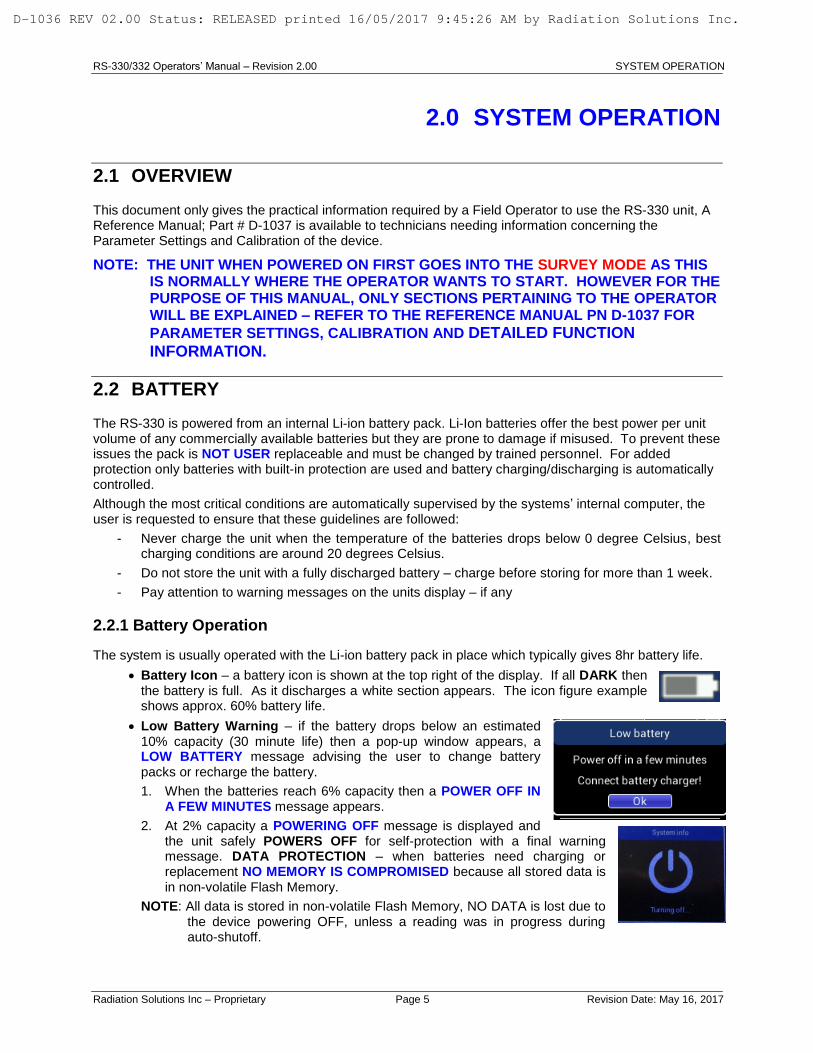
2.2.1 Battery Operation
The system is usually operated with the Li-ion battery pack in place which typically gives 8hr battery life.
Battery Icon – a battery icon is shown at the top right of the display. If all DARK then the battery is full. As it discharges a white section appears. The icon figure example shows approx. 60% battery life.
Low Battery Warning – if the battery drops below an estimated 10% capacity (30 minute life) then a pop-up window appears, a LOW BATTERY message advising the user to change battery packs or recharge the battery.
1. When the batteries reach 6% capacity then a POWER OFF IN A FEW MINUTES message appears.
2. At 2% capacity a POWERING OFF message is displayed and the unit safely POWERS OFF for self-protection with a final warning message. DATA PROTECTION – when batteries need charging or replacement NO MEMORY IS COMPROMISED because all stored data is in non-volatile Flash Memory.
NOTE: All data is stored in non-volatile Flash Memory, NO DATA is lost due to the device powering OFF, unless a reading was in progress during auto-shutoff.
D-1036 REV 02.00 Status: RELEASED printed 16/05/2017 9:45:26 AM by Radiation Solutions Inc.

RS-330/332 Operators’ Manual – Revision 2.00 SYSTEM OPERATION
Radiation Solutions Inc – Proprietary Page 6 Revision Date: May 16, 2017
2.2.2 Battery Charging
The RS-330 has a built-in battery charger that allows the batteries to be recharged while operating the unit (without removing the batteries). In addition the unit can be charged when switched OFF. When the charger is plugged in a YELLOW LED shows that charging is in progress. Light ON = charging, light OFF = charge complete or unplugged, light FLASHING means an error occurred while charging.
NOTE: 12VDC charging (car battery) can be carried out using the supplied car lighter socket cable with an internal fuse for battery protection.
The charging progress is indicated by the battery icon on the display – WHITE = full charge, a pulsing icon means the charge in progress.
NOTE: The supplied Battery Charger must be used at all times as the Manufacturer will not be held responsible for damage to the unit caused by using an improper battery charger. Connecting the wrong type of charger may lead to unpredictable damage of the unit and will invalidate the warranty. (Contact RSI – see Appendix Z for information)
2.3 POWER DEVICE
2.3.1 Power Device (ON)
Press and hold the OK button for approx. 2 seconds until the display lights up, then release.
After a few seconds a “LOADING” message is displayed for approximately 3 seconds, during this time the system is performing complex internal testing to check that all parts of the unit are fully functional – any problems will be reported to the user.
2.3.2 Shutdown Device (OFF)
To switch the unit OFF, choose the Shutdown icon in the Main Display and select
YES. The other way to switch OFF the unit is to press and hold the OK Button for
approx. 10 seconds until the unit automatically switches OFF.
The Operator Menu will display in either the SURVEY Mode or the ASSAY Mode by pressing the OK button with a short CLICK. The UP and DOWN arrows will be lit. Use the DOWN button to scroll to the Main Menu. Use the LEFT and/or RIGHT button to scroll to Shutdown. ENTER the selection by pressing the OK button. The Exit requestor will confirm you want to Shut Down.
PRESS OK (ENTER)
(HOLD)
D-1036 REV 02.00 Status: RELEASED printed 16/05/2017 9:45:26 AM by Radiation Solutions Inc.

RS-330/332 Operators’ Manual – Revision 2.00 SYSTEM OPERATION
Radiation Solutions Inc – Proprietary Page 7 Revision Date: May 16, 2017
2.4 DISPLAY
RSI carried out extensive experimentation to determine the best display to use. The final unit selected is a trans-reflective LED color display. Extensive Field testing showed that a BLACK background with white numbers showed absolutely AUTOMATICALLY to a MONOCHROME mode for external bright sunlight usage. This combination of color balance and light sensor gives excellent readability under all light conditions.
NOTE: About 3 seconds after the units’ Title Screen appears the display changes to the SURVEY MODE.
2.5 EXTERNAL CONNECTIONS
PC Connection: Connect the supplied USB cable to the computer and connect the mini USB connector to the device.
Power & Charging: Connect the supplied power cord (U.S. or EURO) to the Power plug on the device. This will also charge the internal battery.
2.6 CONNECTIVITY
There are 3 ways to connect a unit to a PC for Data Transfer, Parameter change or Remote operation:
a) USB – supports all 3 functions
b) WiFi - supports all 3 functions
Bluetooth (future) – used for covert audio connection
Mini USB Port
Power and Charging Port
External Speaker
LED Indicator
D-1036 REV 02.00 Status: RELEASED printed 16/05/2017 9:45:26 AM by Radiation Solutions Inc.

RS-330/332 Operators’ Manual – Revision 2.00 SYSTEM OPERATION
Radiation Solutions Inc – Proprietary Page 8 Revision Date: May 16, 2017
This Page is intentionally left Blank.
D-1036 REV 02.00 Status: RELEASED printed 16/05/2017 9:45:26 AM by Radiation Solutions Inc.

RS-330/332 Operators’ Manual – Revision 2.00 SURVEY
Radiation Solutions Inc – Proprietary Page 9 Revision Date: May 16, 2017
3.0 SURVEY
3.1 SURVEY MODE
About 3 seconds after the units’ Title Screen appears the display changes to the SURVEY MODE:
The SURVEY display as above has various data components:
a) TOP BAR
Shows various icons and messages:
Current time (time zone can be adjusted)
Various ICONS are shown:
= USB – shows the USB is connected to a PC
= GPS – shows that the integrated GPS system is functioning and collecting data
= RECORDING – shows Data RECORDING in progress and data is being stored in internal memory
= WiFi connected to local network
= Battery charge icon – DARK is full – White shows usage
Time, Active connection (USB, WiFi), GPS signal, Record
Battery status, stabilization
Total count in current spectrum
Background Dose Rate
Dose
History Audio response to help locate the source during the survey. Alarming: If enabled, alarms can occur based on Dose rate, dose, or gamma counts.
STATUS LINE
STATUS LINE
D-1036 REV 02.00 Status: RELEASED printed 16/05/2017 9:45:26 AM by Radiation Solutions Inc.

RS-330/332 Operators’ Manual – Revision 2.00 SURVEY
Radiation Solutions Inc – Proprietary Page 10 Revision Date: May 16, 2017
MESSAGES (STATUS LINE) - typical messages are:
o SYSTEM OK – means Normal Operation
o LOW BATTERY – means battery level is below 10% capacity so needs charging
o SYSTEM ERROR – means the system has automatically detected an error
o STAB ERROR – means the auto stabilization system has problems so Assay data is
compromised
NOTE: See Reference Manual D-1037 for a full list of messages and recommended actions.
b) TOTAL COUNT Display from the Gamma detector in counts/second used for
SURVEY applications – this display is updated 1/second. Max display is 999,999 cps
c) Data table for real-time user information
BG = BACKGROUND – this is the currently computed
local radiation background which is updated automatically
DR = DOSE-RATE – this is the currently computed Dose-Rate in selected units
NOTE: The Dose Rate calculation may not be accurate until the System stabilizes (max 2 minutes), so the DR may show a display something like DR <4738uR. Once Stabilization is OK (Stab icon is visible) then the Dose rate will be correct.
Dose = Accumulated DOSE – this is the instantaneous Dose Rate accumulated from the time the unit was last reset (powered ON)
d) GRAPH DISPLAY – this real-time graphic display is updated 1/second and displays 120 seconds of current data. The data is auto scaled vertically as changes occur. This graph is useful to see small changes in the local radiation levels that have occurred which the user may have missed when scanning.
The lower X-axis shows the time the data was taken.
3.2 AUDIO
The RS-330 has a specially designed audio capability that is updated 20 times/second to ensure maximum SURVEY usage. This audio is used to locate the maximum radiation level and its’ audio tone varies with intensity. So at "NORMAL” background radiation levels the audio is silent with the very occasional beep to show it is active. When the radiation level exceeds the programmed threshold, the audio tone begins and the pitch increases as the radiation intensity increases. Thus the unit can be easily used in an EYES-FREE mode to locate radioactive material.
3.3 MENU
During SURVEY, if the user presses OK, a menu appears permitting various options to be selected. The Up/Down Arrow joystick keys permit user selection on the display. Pressing the joystick OK button selects the highlighted function.
CONTINUE – this selection moves back to the SURVEY display with no other action (often used by a user pressing OK by accident)
IDENTIFY – this starts the Identify process detailed in Chapter 5.0.
D-1036 REV 02.00 Status: RELEASED printed 16/05/2017 9:45:26 AM by Radiation Solutions Inc.

RS-330/332 Operators’ Manual – Revision 2.00 SURVEY
Radiation Solutions Inc – Proprietary Page 11 Revision Date: May 16, 2017
ASSAY – this starts the Assay process detailed in Chapter 4.0.
START RECORD – permits data recording
PAUSE – pauses recording
REACQUIRE BG – permits the user to “reset” the local background
MAIN MENU – returns the user back to the Top menu
3.3.1 Start Record
In the SURVEY Mode users often want to record data to be used for traversing or mapping applications.
The RS-330 has an extensive recording storage capability.
If the START RECORD option is selected the “circle R” icon is displayed at the top of the display
to show that recording is in progress.
Data for all sensors and GPS is recorded 1/second with 10,000 samples of data storage provided = 2.8hrs of continuous data.
Select OK – STOP RECORD to terminate the recording process.
3.3.1.1 Store Note / Record Note
When the RS-330 is placed in the RECORD Mode the User can add an Audio Note to the spectrum data at any time. This process is used to record an audio note of information relevant to the sample. This could be LOCATION, WEATHER CONDITIONS or whatever data is useful for future analysis. This option utilizes a small microphone embedded in the unit just below the display (MIC). In order to ensure the system is fully watertight unfortunately the microphone must be masked for protection. This means that for best audio results the User should “speak” as close as possible to the display unit with a reasonably clear voice level. Experimentation will show the best procedure to suit the user.
The process is as follows IF THE RS-330 is in the RECORD MODE:
o Press OK - STORE NOTE (SURVEY Mode) OK – RECORD NOTE (Assay Mode) and a new display appears, the rest of the procedure is the same for either the Survey or Assay Mode(s)
Select RECORD NOTE in the new display. The upper progress bar shows the time available to record the note = 15 seconds. Speak reasonably loudly and clearly (close to the MIC port on the RS-330 front panel) during the time the progress bar is visible. If finished you
D-1036 REV 02.00 Status: RELEASED printed 16/05/2017 9:45:26 AM by Radiation Solutions Inc.

RS-330/332 Operators’ Manual – Revision 2.00 SURVEY
Radiation Solutions Inc – Proprietary Page 12 Revision Date: May 16, 2017
can press STOP or wait for the timeout. The recording will be played back before the Record Note Options
screen appears.
When the note is complete an Options Screen appears and the user can:
PLAY NOTE = replay the note to be sure all is OK
RECORD NOTE – make a new recording
STORE NOTE – log the note into memory where it can be retrieved later (integrated with the data)
DISCARD NOTE – cancel the note
Click on Store note when complete. You will not be given any prompt telling you that a note was saved or given an ID.
Repeat the procedure as often as you like. Multiple notes can be taken per survey.
You will not see any indication of a note when the data is read from the device into RSAnalyst. When the survey data is exported all the audio notes will be exported along with it.
3.3.2 Pause
This command “freezes” the instrument TEMPORARILY and is used to
REVIEW data.
In this PAUSE Mode – the user can use the ARROW keys go back into the previously recorded data to review data. Note that current data is buffered during this PAUSE for review process. Press OK and scroll to RESUME, it then runs the data display to the CURRENT data buffered in memory so no data is lost during the review process.
3.3.3 Reacquire BG
The local Radioactive Background (BG) is used to set the SURVEY audio Threshold. This BG level is stored in the unit when it is powered ON.
Inside the unit various settings select the best BG usage. Typically the setting selected means the BG reference level is being continually updated to utilize the best levels.
The reason this is important is only for AUDIO surveying because as noted above the local BG is used to select the threshold level that the audio SURVEY tool uses to enable its audio.
A key problem here is best explained with an example, using the figure below. The example shows a FIELD condition. In this example for simplicity the device is being used to locate radioactive material in three AREAS of Interest:
D-1036 REV 02.00 Status: RELEASED printed 16/05/2017 9:45:26 AM by Radiation Solutions Inc.

RS-330/332 Operators’ Manual – Revision 2.00 SURVEY
Radiation Solutions Inc – Proprietary Page 13 Revision Date: May 16, 2017
160cps (Green) this is
the local background AWAY FROM THE AREAS of Interest because the unit is seeing radiation from all around it.
120cps (Yellow) – this is
the background at AREA 1 this displays the local background so it is significantly lower.
If the unit BG is set at the 160cps – then the Audio Threshold = 223cps so it will NOT sound the audio when the 200cps source location is passed.
200cps (Red) - However if the unit is positioned at the 120cps point and then the REACQUIRE
BG selection is made, the Audio Threshold is then 175cps so the 200cps source will give an audio response.
NOTE: Of course if the radiation source signal is quite large then such a small BG change has little affect, so under most circumstances the REACQUIRE BG step is not required. However if you scan the area and find NOTHING, using the REACQUIRE BG process defined above may make the source easier to find.
3.3.4 Onfly Assay Results
When the Survey Histogram is ready use the joystick and click it to the right, this opens the Onfly assay results screen.
Click Joystick to RIGHT
The Display changes to Onfly Assay results, clicking the joystick to the LEFT will toggle the screen back to Survey Histogram
D-1036 REV 02.00 Status: RELEASED printed 16/05/2017 9:45:26 AM by Radiation Solutions Inc.

RS-330/332 Operators’ Manual – Revision 2.00 SURVEY
Radiation Solutions Inc – Proprietary Page 14 Revision Date: May 16, 2017
Customers Recording Data in OnTheFly Assay mode may find that if the device had been previously setup for Record Mode that the sequential order or chronological numbering for saved files will be affected, as the device is also storing data for OnTheFly storage. It appears that the sequential numbering is skipping as the device is storing data on the fly. Each Record assay and OnTheFly assay is assigned a unique ID. From affected customer`s data it appears that assays were being saved while the “OnTheFly” option was started. In this case the unit would assign an ID to the Manual (Record) assay and skip the OnTheFly assay, thus resulting in non-sequential ID numbering. To prove this is happening compare the time stamps of the exported “Manual assay” data and the “OnTheFly assay” data. When you export the data the “OnTheFly assays” will be the ones that have a blank space in the total column while the Manual assays will contain all the data.
D-1036 REV 02.00 Status: RELEASED printed 16/05/2017 9:45:26 AM by Radiation Solutions Inc.

RS-330/332 Operators’ Manual – Revision 2.00 ASSAY
Radiation Solutions Inc – Proprietary Page 15 Revision Date: May 16, 2017
4.0 ASSAY
The RS-330 Multipurpose Gamma Center is a highly sensitive system. The large volume detector with a 1024 channel spectrometer enables the use of highly sophisticated algorithms for gamma spectra evaluation. A unique evaluation algorithm allows determining concentration of natural radioactive elements as well as manmade radioisotopes in various applications.
Besides most common applications in Geology, the RS-330 also has applications for tasks in Waste Management, Environmental Measurements etc. The Assay process is fully automated and does not require special user’s effort and data results give the user all the necessary information for detailed analysis.
4.1 STABILIZATION
NOTE: For accurate Assay results the system must be stabilized to remove any effects from local temperature changes or component aging inside the unit. This is an automatic process that is
carried out continuously.
If the system is NOT stabilized the Assay will be in error. The user is advised by audio/visual message. If the user attempts to make an Assay reading when the system is not ready, a Warning Message will appear on the display to advise the user.
This icon on the top right of the display is also a visual indication that the system is fully stabilized and is good-to-go.
NOTE RE AUTO STABILIZATION: ALL electronic systems drift with time due to temperature effects as well as component aging. Any drifts causes spectral distortion so the ASSAY is compromised. The techniques used to remove these drifts effects on the spectra are called STABILIZATION. Unlike older technology units that require embedded sources for Gain stabilization, the RS-330 uses LOCAL RADIATION BACKGROUND as a reference. From power ON it takes typically 3-5 minutes for the system to be “good to go” and the Stab icon appears. As time progresses the RS-330 automatically analyses local radiation background and if any drift is seen it is automatically corrected WITH NO USER INTERACTION. If the auto analysis system fails for any reason the user is alerted that ASSAY is compromised, but this is a very rare event.
NOTES RE AUTO-STABILIZATION:
a) When the unit is powered OFF, it remembers where the auto-gain settings are so when powered ON again it can start at these same settings. Usually this means a fast start up with a 2-3 minute warmup time sufficient to get final stabilization.
b) TEMPERATURE CHANGE – if there is a very significant temperature change between power OFF and power ON especially if the unit is OFF for a long period, startup is slower. Under these conditions it could take the unit up to 15 minutes to auto-stabilize
IF THE UNIT TAKES LONGER THAN 15 MINUTES TO STABILIZE PLEASE CONTACT RSI. (See Appendix – Z)
D-1036 REV 02.00 Status: RELEASED printed 16/05/2017 9:45:26 AM by Radiation Solutions Inc.

RS-330/332 Operators’ Manual – Revision 2.00 ASSAY
Radiation Solutions Inc – Proprietary Page 16 Revision Date: May 16, 2017
4.2 ASSAY MODE
As noted above, ASSAY cannot be started before the system auto-stabilization is OK, once the device is stabilized proceed as follows:
a) Select ASSAY from the Survey Operator Menu (to the right) or the Main Menu (below) and press OK to activate this function.
b) The ASSAY routine starts and the following display is seen.
NOTE: The label and details of the display are controlled by the Analysis Method selected. For the RS-332 with internal collimator the Analysis Method would be Colim_300.
c) After 30 seconds, data appears on the display and the data is updated every 30 seconds until the sample ends (default setting is 5 mins but user can change).
d) At the bottom of the display the sample period progress is seen (7/300 = 7 seconds of a 300 second sample).
e) At the end of the sample period the final results are seen, as explained below
4.2.1 Assay Results Screen
The figure (to the right) shows a screen with typical Assay results explained as follows:
a) Col 1 – a numeric list of all the data results
b) Col 2 – the label of the data typically:
K (Potassium-40)
U (Uranium/Radium)
Th (Thorium-232)
Dose
Dose rate
c) Col 3 – data results (note that in the Cal file a lower detection limit is set as below this level the data may be inaccurate. e.g. <3.0 means the low detection limit was set at 3.0 and the actual results are lower than this.
d) Col 4 – data units (%, ppm, uSv etc.)
D-1036 REV 02.00 Status: RELEASED printed 16/05/2017 9:45:26 AM by Radiation Solutions Inc.

RS-330/332 Operators’ Manual – Revision 2.00 ASSAY
Radiation Solutions Inc – Proprietary Page 17 Revision Date: May 16, 2017
4.2.2 Spectrum Display
While the data is accumulating or at the end of the sample, using the Left/Right Arrow joystick keys the user can switch the display between the RESULTS and the SPECTRUM Display(s). RESULTS SPECTRUM DISPLAY
The Spectrum Type can be changed in the SPECTRUM Display by pressing the OK button and a new sub-menu appears. Scroll to Spectrum Type, which will open the Spectrum type options.
NOTE: LINEAR Spectrum Type is shown above.
While in the SPECTRUM Display, press OK and a new sub-
menu appears.
NOTE: The sub-menu appears differently when the OK button is pushed, before or after the measurement
is complete.
Select ‘Explore spect’ to go into the spectrum display mode (the magnifying glass icon shows that you are in this mode). In this mode the joystick arrow keys can be used to move a cursor along the X-axis to see Channel #/Energy and Counts at the channel required and the Up/Down arrow keys change the Vertical Scale.
The main spectrum is displayed in YELLOW but selected ROIs are highlighted in RED.
LEFT – ARROW – RIGHT
D-1036 REV 02.00 Status: RELEASED printed 16/05/2017 9:45:26 AM by Radiation Solutions Inc.

RS-330/332 Operators’ Manual – Revision 2.00 ASSAY
Radiation Solutions Inc – Proprietary Page 18 Revision Date: May 16, 2017
The Spectrum Display can be changed from Linear to Compressed at any time by pressing the OK button to open the sub menu and choosing Spectrum type.
NOTE: Pressing the OK button will open a sub-menu with options to Autoscale or Zoom in the graph.
To exit this screen select OK – then Exit exploring to go back to the normal mode of operation.
4.2.3 Core Method - Sampling
Core Method is available for both RS-330 and 332. It comes pre-installed on the RS-332 with internal collimator the Analysis Method would be Colim_300. Customers wishing to use their existing RS-330 devices need to contact RSI for the correct add-on or order this option when purchasing new units. Core method is part of the “Assay” (refer to Section 5.2). After setting up Core mode, When taking a core measurement, first choose “Assay”. Turn Core method ON as follows: Settings > Measurement > Core mode > Choose Enable
Then choose the desired measurement method. Note that “Colim_300” indicates the colimated RS-332 model.
DO NOT choose this option if you have RS-330 model. Choose the file installed on the RS-330 for Core Mode.
When taking a new core measurement. Select “Assay”. The window below will pop up to guide the user, fill out the information for the new core, a scroll bar is located on the right side, scroll down to complete the form.
D-1036 REV 02.00 Status: RELEASED printed 16/05/2017 9:45:26 AM by Radiation Solutions Inc.

RS-330/332 Operators’ Manual – Revision 2.00 ASSAY
Radiation Solutions Inc – Proprietary Page 19 Revision Date: May 16, 2017
When the form is complete choose “Save and Start measure” to begin the procedure of spectrum analysis.
The icon at the bottom left of the screen is the option to toggle between the table and spectrum
Click the “OK” button to display the menu items. The options are; Explore spect, Survey, Spectrum type or Main Menu. Choose to explore spectrum or change Spectrum Type.
User can move the cursor left and right.
The measurement result(s) are automatically saved and a prompt will display the following options: Start – Start the next measurement, New – begin a new measurement, or go back to the Main Menu.
The depth for the next measurement was calculated from the core info the user had previously input. If the User requires changing the depth, it can be changed by choosing it and entering the data with the displayed keyboard.
D-1036 REV 02.00 Status: RELEASED printed 16/05/2017 9:45:26 AM by Radiation Solutions Inc.

RS-330/332 Operators’ Manual – Revision 2.00 ASSAY
Radiation Solutions Inc – Proprietary Page 20 Revision Date: May 16, 2017
RSAnalyst - Refer to RSAnalyst User Manual D-1180 for more information. After downloading the data into RSAnalyst, choose Measure Data from tool bar on left.
Choose Core Measurements, and Core Log from All Measurements, the Graph tab shows K, U, Th result(s) graph and API unit
D-1036 REV 02.00 Status: RELEASED printed 16/05/2017 9:45:26 AM by Radiation Solutions Inc.

RS-330/332 Operators’ Manual – Revision 2.00 IDENTIFY
Radiation Solutions Inc – Proprietary Page 21 Revision Date: May 16, 2017
5.0 IDENTIFY
Enter the Identify Mode by either:
Selecting the IDENTIFY icon from the Main Menu (Left Figure)
Selecting the IDENTIFY option from the Survey Mode Menu (Right Figure)
5.1 IDENTIFY MODE
At the end of the 60 second count period the unit will beep to show that the analysis sample is complete. An automatic analysis takes place and the results are displayed as shown.
o Status - the system is setup so that every time an IDENTIFY is carried out a requestor will pop-up before changing modes asking user if the sample should be saved.
o ID 1 = this shows that these data are saved as Nuc ID data point #1. When the memory is reset (purged) it resets this counter to start at “1”.
o K-40 – NAT – shows the Isotope ID = Potassium 40, it is a NATural source type.
5.1.1 Identify Menu
After viewing the data ID results display, pressing OK gives this display with more functions: In this menu the Up/Down Arrow keys permit user selection which is highlighted. Pressing OK selects the highlighted function.
a) CONTINUE – returns to the IDENTIFY Mode.
b) SAVE – saves the spectrum in memory, note if Autosave has already been implemented then Save writes the same sample on top of the original one.
c) EXTEND IDENTIFY - extend the sample for an additional period. If the first sample is inadequate over the set time period, adding another sample period may suffice. If the results show NON-IDENTIFIED then a sensible step is to select the EXTEND IDENTIFY option. This then adds another 60 second sample (if set as the time period) to the first sample to make a 120 second sample.
When the sample is complete the Nuclide ID analysis takes place and the results displayed. There is NO LIMIT to the number of times that EXTEND IDENTIFY can be used but in practice in most cases if no result is obtained in 180 seconds then there is a high probability that the data signal is too low for analysis. In this case good practice is to go back to SURVEY, relocate the source maximum point then repeat the IDENTIFY process. Note that each extend identify adds to the original sample so the ID# of the data does not change, but inside the data the extra length sample period is noted.
d) NEW IDENTIFY – this permits the user to start a completely new IDENTIFY process exactly the same process as shown above.
D-1036 REV 02.00 Status: RELEASED printed 16/05/2017 9:45:26 AM by Radiation Solutions Inc.

RS-330/332 Operators’ Manual – Revision 2.00 IDENTIFY
Radiation Solutions Inc – Proprietary Page 22 Revision Date: May 16, 2017
e) RECORD NOTE – this process is used to record an audio note of information relevant to the sample. This could be LOCATION, LICENSE PLATE or whatever data is useful for future analysis. This option utilizes a small microphone embedded in the unit just below the display. In order to ensure the system is fully watertight unfortunately the microphone must be masked for protection. This means that for best audio the user should “speak” as close as possible to the display unit with a reasonably clear voice level. Experimentation will show the best procedure to suit the user. See Section 3.3.1.1 for detailed information.
f) SURVEY – Goes to the SURVEY Mode.
MAIN MENU – returns to the Main Menu for additional selections
5.1.2 Identify – Graphic Menu
Click on OK button to open the Options Menu in the Graphic Window.
a) CONTINUE – Returns to the Identify Mode.
b) SAVE – Manually saves the sample to the hard drive before changing modes.
c) EXTEND IDENTIFY - Extends the sample for an additional period. If the first sample over the time period is inadequate, adding another sample period may suffice. If the results show NON-IDENTIFIED
d) NEW IDENTIFY – Repeats the Identify process.
e) EXPLORE SPECT – See Section 5.1.3.
f) RECORD NOTE – Permits data recording – see Section 3.3.1.1
g) SURVEY – Opens the SURVEY Mode
h) SPECTRUM TYPE – Allows the User to choose the Spectrum Type as LINEAR or COMPRESSED.
i) MAIN MENU – Opens the Main Menu.
5.1.3 Exploring the Spectrum
Click on the OK button to open the Options Menu in the Graphic Window. Scroll to Explore Spect to open the Spectrum window. The Spectrum Window opens showing the spectrum that has just been analyzed and the user can use the LEFT/RIGHT Arrow Keys to move a cursor along the spectrum to show Channel/Energy and Counts at that location.
D-1036 REV 02.00 Status: RELEASED printed 16/05/2017 9:45:26 AM by Radiation Solutions Inc.

RS-330/332 Operators’ Manual – Revision 2.00 IDENTIFY
Radiation Solutions Inc – Proprietary Page 23 Revision Date: May 16, 2017
Clicking OK in the Explore Spect window opens the following menu of tools:
o CONTINUE – returns User to the spectrum graph.
o AUTOSCALE sets the vertical scale automatically to contain the maximum. This will place a white magnifying glass in the upper
right corner of the graph.
o ZOOM = permits changing the Vertical scale using the Arrow Up/Down keys. This will place a green magnifying glass in the
upper right corner of the graph.
o SPECTRUM TYPE - Toggles the graphic between LINEAR and COMPRESSED.
o EXIT EXPLORING – Returns to the Identify Mode.
NOTE: The SPECTRUM Menu is specific to the Identify Mode.
D-1036 REV 02.00 Status: RELEASED printed 16/05/2017 9:45:26 AM by Radiation Solutions Inc.

RS-330/332 Operators’ Manual – Revision 2.00 IDENTIFY
Radiation Solutions Inc – Proprietary Page 24 Revision Date: May 16, 2017
This Page is intentionally left Blank.
D-1036 REV 02.00 Status: RELEASED printed 16/05/2017 9:45:26 AM by Radiation Solutions Inc.

RS-330/332 Operators’ Manual – Revision 2.00 DATA STORAGE and PC CONNECTIONS
Radiation Solutions Inc – Proprietary Page 25 Revision Date: May 16, 2017
6.0 DATA STORAGE and PC CONNECTIONS
6.1 DATA STORAGE
The RS-330 has a large non-volatile Solid State Memory drive, so data is automatically saved to memory when power is switched OFF. Data recordings are essentially unlimited for measured data, voice comments and information about the location of the unit as well as auto-logged data of system performance to permit analysis in case of issues.
To view the Data memory contents, select Storage from the Main Menu then select any of the stored data sets.
Identify (refer to Section 6.1.1)
Assay (refer to Section 6.1.2)
Survey (refer to Section 6.1.3)
Stabilization (refer to Section 6.1.4)
Calibration (refer to Section 6.1.5)
System Logs (refer to Section 6.1.6)
Once the category is selected, the user can choose to inspect ALL RECORDS or filter the data by Date and Time range (from a calendar).
Note: This is typical for all selections.
First enter the START Date and Save, the Start date will appear on the DATE Options screen. Enter the END Date and Save, the End date will appear on the DATE Options screen. Choose SEARCH and the chosen Storage Option will collect data from the requested time period.
D-1036 REV 02.00 Status: RELEASED printed 16/05/2017 9:45:26 AM by Radiation Solutions Inc.
RS-330/332 Operators’ Manual – Revision 2.00 DATA STORAGE and PC CONNECTIONS
Radiation Solutions Inc – Proprietary Page 26 Revision Date: May 16, 2017
6.1.1 Identify Log
The Identify logs; consists of ID results and spectra. Pressing OK gives additional options:
The Selections are:
CONTINUE – returns to the previous display.
RELOAD – reloads the data into the database for display and selection.
GRAPH – select a data file from Identify Logs, then press OK and the selected data file is shown as a graphical display with custom section.
RESULTS Nuc – select a data file from Identify Logs, then OK and the selected data file data results are shown.
RESULTS Peak – select a data file from Identify Logs, then OK and the peak results are shown.
BACK TO LOGS – back to the Logs menu.
6.1.2 Assay Log
The Assay logs; consists of assay results and spectra. Pressing OK gives additional options:
CONTINUE – this goes back to the previous display.
RELOAD – reloads the data into the database for display and selection.
GRAPH – select Graph from the Menu, then press OK and the selected data file is shown as a graphical display with custom section.
RESULTS – select Results from the Menu; then press OK and the selected file data results are shown.
BACK TO LOGS – back to the Logs menu
D-1036 REV 02.00 Status: RELEASED printed 16/05/2017 9:45:26 AM by Radiation Solutions Inc.

RS-330/332 Operators’ Manual – Revision 2.00 DATA STORAGE and PC CONNECTIONS
Radiation Solutions Inc – Proprietary Page 27 Revision Date: May 16, 2017
6.1.3 Survey Log
The Survey logs; consists of survey and analysis results. Once in this mode then pressing OK gives additional options:
CONTINUE – this goes back to the previous display
RELOAD – reloads the data into the database for display and selection.
GRAPH – select Graph from the Menu, then press OK and the selected data file is shown as a graphical display with custom section.
Pressing OK will open a submenu of tools; the selections being Continue, Autoscale, Zoom and Back to menu.
BACK TO LOGS – back to the Logs menu. .
6.1.4 Stabilization Log
The stabilization log offers a table of the most important stabilization inputs and outputs. There are in columns: Index, Date, and Time of stabilization event and stabilization result. The stabilization result is OK when unit’s gain is corrected but any stabilization errors will have a message. The next six columns are used for detailed information about peak differences in channels of nominal peak position, information about high voltage adjustment before and after stabilization and fine gain adjustment before and after stabilization. The information is primarily for specialist support. In case of problems, RSI may ask for the Stabilization Log to be emailed – see PC connections below.
Once in this mode then pressing OK gives additional options:
CONTINUE – this goes back to the previous display
RELOAD – reloads the data into the database for display and selection
BACK TO LOGS – back to the Logs menu.
D-1036 REV 02.00 Status: RELEASED printed 16/05/2017 9:45:26 AM by Radiation Solutions Inc.

RS-330/332 Operators’ Manual – Revision 2.00 DATA STORAGE and PC CONNECTIONS
Radiation Solutions Inc – Proprietary Page 28 Revision Date: May 16, 2017
6.1.5 Calibration Log
Future usage
6.1.6 System Log
The system log is used to file all important system information. In case of problems, RSI may ask for the Stabilization Log to be emailed – see PC connections below.
RSI supplies an ancillary program called RSAnalyst to enable easy parameter setup for the users (Refer to the Reference Manual D-1037 for more information). This allows the sophisticated user with multiple systems to be sure that system Parameters are the same for each unit. Doing this manually as described above is onerous so the PC program makes it simpler.
NOTE: For security reasons some parameters can ONLY be set via the PC to prevent incorrect system operation by unauthorized personnel.
6.2 PC Software Download
Setup a new sub-directory on the USER PC – named as required - (e.g. RSI). Click on the link sent to you by RSI Service (see Appendix Z for contact information). Choose SAVE when requested, then select the correct sub-directory to download the software to (e.g. RSI). Open this file and UNZIP it as required.
6.3 Install RSAnalyst
NOTE: This software has been designed to run on all current Microsoft OS systems. The software has been successfully installed and heavily tested on a variety of computers including Win2000, WinXP, WinXP Professional, Vista, System 7, System 8.1 and System 10. A minority of users have experienced installation problems, concerning computer setup configurations. If problems persist, contact RSI for support.
Use Windows Explorer to look at the sub-directory
where the downloaded file exists (e.g. RSI) – locate the file named setup_rs_2.x.xx.exe. Double click this file then select RUN.
D-1036 REV 02.00 Status: RELEASED printed 16/05/2017 9:45:26 AM by Radiation Solutions Inc.
RS-330/332 Operators’ Manual – Revision 2.00 DATA STORAGE and PC CONNECTIONS
Radiation Solutions Inc – Proprietary Page 29 Revision Date: May 16, 2017
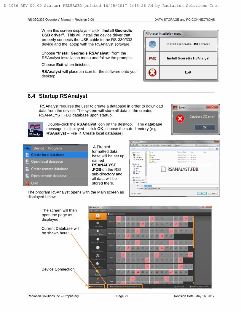
When this screen displays – click “Install Georadis USB driver”. This will install the device driver that properly connects the USB cable to the RS-330/332 device and the laptop with the RSAnalyst software.
Choose “Install Georadis RSAnalyst” from the RSAnalyst installation menu and follow the prompts.
Choose Exit when finished.
RSAnalyst will place an icon for the software onto your desktop.
6.4 Startup RSAnalyst
RSAnalyst requires the user to create a database in order to download data from the device. The system will store all data in the created RSANALYST.FDB database upon startup.
Double-click the RSAnalyst icon on the desktop. The database message is displayed – click OK, choose the sub-directory (e.g. RSAnalyst – File Create local database).
A Firebird formatted data base will be set up named RSANALYST .FDB on the RSI sub-directory and all data will be stored there.
The program RSAnalyst opens with the Main screen as displayed below: The screen will then
open the page as displayed: Current Database will be shown here:
Device Connection
D-1036 REV 02.00 Status: RELEASED printed 16/05/2017 9:45:26 AM by Radiation Solutions Inc.

RS-330/332 Operators’ Manual – Revision 2.00 DATA STORAGE and PC CONNECTIONS
Radiation Solutions Inc – Proprietary Page 30 Revision Date: May 16, 2017
6.4.1 Connect Device
NOTE: Before starting be sure to connect the USB cable between the device and the PC. To connect a device (RS-330/332) go to the Menu located at the top of the Main Screen and choose Device Connect Device.
Clicking menu item Device Connect Device opens the Connect Dialog box, choose USB and select the USB device shown. Click the Connect button.
NOTE: Refer to the RSAnalyst User Manual (D-1180) for
information concerning the operation and use of the RSAnalyst software.
D-1036 REV 02.00 Status: RELEASED printed 16/05/2017 9:45:26 AM by Radiation Solutions Inc.

RS-330/332 Operators’ Manual – Revision 2.00 ALARMS
Radiation Solutions Inc – Proprietary Page 31 Revision Date: May 16, 2017
7.0 ALARMS
The RS-330 has a very sophisticated alarm capability that can be adjusted to suit any user requirements. Note that this Audio/Visual ALARM capability is separate from the normal audio tone change with intensity used to locate radioactive sources. The main purpose of the ALARM capability is to set various safety levels into the unit to warn of hazardous conditions.
NOTE: ALARMS is not active in the Main Menu until the parameter is turned ON under the SETTINGS Alarms menu. Once turned ON, ALARMS will be displayed in the Main Menu. The following Alarms can be activated; Gamma, Dose Rate and Dose, and the threshold for these can be setup (refer to the Reference Manual D-1037 for information on Threshold Settings). The function of these ALARMS is as follows:
7.1 GAMMA ALARM
The Gamma Alarm capacity permits the system to alarm the user if there is a small change in the local radiated Gamma field. Since the local Background fluctuates randomly due to physics, for best sensitivity the LOCAL RADIOACTIVE BACKGROUND is used as a base for alarm analysis.
When the unit is powered ON, it automatically stores a 3 second average of the local background (BG) in memory. The Gamma Alarm Threshold is set to Standard Deviation (SD) units with the threshold above this background.
For statistical reasons if a 3SD level was set then an alarm would occur typically within 100 seconds due to normal background fluctuations, so these low levels have no merit.
If the Gamma Alarm is to be used the User should determine the alarm threshold level, determine its’ amplitude then select a SD setting to ensure reliable detection. In practice setting the threshold 3SDs below the peak level of interest is a conservative approach.
ALARM ACTION: if the radiation levels exceed the preset Threshold the following occurs:
A very loud audio warning occurs and a pop-up box appears displaying a clear warning as shown.
MUTE HORN is highlighted so press OK to cancel the loud audio
An ALARM icon appears on the top of the display
A G ALARM message appears on the top of the display showing this is a Gamma Alarm
A new pop-up box appears with options:
D-1036 REV 02.00 Status: RELEASED printed 16/05/2017 9:45:26 AM by Radiation Solutions Inc.

RS-330/332 Operators’ Manual – Revision 2.00 ALARMS
Radiation Solutions Inc – Proprietary Page 32 Revision Date: May 16, 2017
o CONTINUE – if this is selected the pop-up box is removed but the Alarm Icon stays in place as well as the G1 ALARM message so this means the Alarm has been acknowledged but not removed. If this option is selected then the Top Menu ALARMS icon is selected to finally remove the alarm. In most cases this is not a useful option so it is not recommended for normal use.
o RESET ALARMS – this selection cancels the alarm so the pop-up box is removed, the alarm icon and message are also removed
o NOTE – allows user to insert an Audio Note is the manner described previously
NOTE: IN MOST GEO APPLICATIONS, THE GAMMA ALARM CAPABILITY HAS LITTLE MERIT BECAUSE THE USER WILL UTILIZE THE AUDIO AND COUNT RATE VARIANCE TO LOCATE THE SOURCE OF INTEREST IN SURVEY MODE.
7.2 DOSE RATE ALARM
The Dose Rate Alarm capability permits the user to alarm the system if there is a potentially hazardous radiation field detected for personnel safety.
In normal GEO Survey activities very high levels of radiation are extremely unlikely but the Dose Rate Alarm can be set to a level that is acceptable to local surveying and will alarm if real hazard levels occur.
For this reason the Dose Rate Alarm is set at a high level consistent with user safety.
ALARM ACTION: if the radiation levels exceed the preset Threshold the following occurs:
A very loud audio warning occurs and a pop-up box appears on the display
A pop-up box displays a clear warning as shown.
Users should move at least 10ft (3m) away then select MUTE HORN
The unit will wait 10 seconds and then test the alarm level again – if above the level the alarm sequence is repeated.
NOTE: The Alarm Threshold selected should be carefully chosen to a level that is acceptable to the local operation. In most cases this can be quite a high level setting because when the alarm occurs the user immediately moves away so Exposure hazard is extremely limited. Setting a low level for this alarm will interfere with normal survey operations so it is recommended that this alarm level be reserved for real hazard levels only.
7.3 DOSE ALARM
The Dose Alarm capacity permits the user to alarm the system if there is a potentially hazardous radiation field detected for personnel safety.
It must be noted that the DOSE ALARM accumulates all the Dose Rate data that occurs and is intended to be used to limit the total Dose Accumulation to the user to a level determined by local regulations and operational restrictions.
NOTE: THAT WHEN THE DOSE ALARM ACTIVATES, IT OF COURSE CANNOT BE RESET BECAUSE THE DOSE LEVELS WILL CONTINUE TO ACCUMULATE. THE ONLY WAY TO RESET THESE DOSE LEVELS IS TO POWER OFF THE UNIT WHICH RESETS THE DOSE ACCUMULATION TO ZERO ON POWER ON.
D-1036 REV 02.00 Status: RELEASED printed 16/05/2017 9:45:26 AM by Radiation Solutions Inc.

RS-330/332 Operators’ Manual – Revision 2.00 ALARMS
Radiation Solutions Inc – Proprietary Page 33 Revision Date: May 16, 2017
In normal Survey activities very high levels of radiation are extremely unlikely as in the vast majority of cases the radioactive source is located inside a vehicle or container and the intervening material absorbs a huge amount of the radiation.
However in rare cases a vehicle/container could contain a breached source (a source could have dropped and been damaged) in which case local radiation fields could be hazardous.
For this reason the Dose Alarm is set at a high level consistent with user safety.
ALARM ACTION: if the radiation levels exceed the preset Threshold the following occurs:
A very loud audio warning occurs and a pop-up box appears on the display.
A pop-up box displays a clear warning as shown.
Users should move at least 10ft (3m) away then select MUTE HORN.
The unit will wait 10 seconds and then test the alarm level again – if above the level the alarm sequence is repeated.
As noted above the unit must be powered OFF to reset this alarm level.
NOTE: The Alarm Threshold selected should be carefully chosen to a level that is acceptable to the local operation. In most cases this can be quite a high level setting because when the alarm occurs the operator should immediately moves away to limit the Exposure Hazard. Setting the alarm threshold to low level will interfere with the normal survey operations, so it is recommended that this alarm level be reserved for real hazard levels only.
D-1036 REV 02.00 Status: RELEASED printed 16/05/2017 9:45:26 AM by Radiation Solutions Inc.

RS-330/332 Operators’ Manual – Revision 2.00 ALARMS
Radiation Solutions Inc – Proprietary Page 34 Revision Date: May 16, 2017
This Page is intentionally left Blank.
D-1036 REV 02.00 Status: RELEASED printed 16/05/2017 9:45:26 AM by Radiation Solutions Inc.

RS-330/332 Operators’ Manual – Revision 2.00 Appendix A TECHNICAL DATA
Radiation Solutions Inc – Proprietary Page 35 Revision Date: May 16, 2017
Appendix A TECHNICAL DATA
Detector:
RS-330: NaI (Tl), volume 345 cm3, dimensions 76 x 76 mm (3“x 3“), resolution FWHM at 662keV, less
than 7, 2%.
RS-332: BGO, volume 104 cm3, dimensions 50.8 x 50.8 mm (2“x 2“), resolution less than 11.5%,
shielded with 25mm (1”) of lead.
Spectrometer: – 256 and 1024 channel, Energy Linearity Corrected, Pile Up Rejecter, Dead-time correction. Energy range 15keV – 3.0MeV
Scintillometer: – Sampling period 20/second
Gamma ray sensitivity: (1MBq Cs-137 1 m): RS-330 = 386 cps, RS-332 = 160 cps
Dose meter: Dose rate measurement range: Cs-137: 0.1 nSv/hr. 100 microSv/hr.
Energy compensation range: 30keV – 1500keV
Gain stabilization: Based on Naturally Occurring Radio Isotopes. Gain stabilized continuously in fully automated mode.
Sensitivities: Single measurement of areal soil contamination. Time of measurement 300s
Sensitivities are in minimum detectable concentrations/activities (Cs-137)
Potassium: 0.3%
Uranium: 0.9 ppm
Thorium: 1.5 ppm
Cesium 137: 400 Bq/m2
Spectra evaluation: Unique spectral analyze method, calibrated for different geometries and application. Measuring methods and Calibration are User Programmable.
Measuring modes: Single and repeated measurement mode
Display: Graphic, Color, Transflective LCD, 360 x 240 dots, 72 x 54 mm (3.5”), Sunlight readable
Audio: Speaker, diameter 28 mm + Built-in Microphone
Data Storage: 8Gb (approximately 2000 samples with full Spectra, GPS and Voice Message)
GPS: 2.5m CEP
Communication: Data Transfer, Remote Control and Diagnostic by:
USB 2.0
WiFi 802.11n
Power: Rechargeable Li-ion 7.2 V / 6600 mAh
– minimum 10 hours of measurement @ 20 °C.
External AC adapter (12 V / 1 A) for charging or measurement
Remote control: Full remote control via WiFi and USB, real time data transfer
Position: Integrated GPS receiver, GPS navigate down to –162 dBm and -148 dBm cold start
Date and time precision: Synchronized with GPS
D-1036 REV 02.00 Status: RELEASED printed 16/05/2017 9:45:26 AM by Radiation Solutions Inc.

RS-330/332 Operators’ Manual – Revision 2.00 Appendix A TECHNICAL DATA
Radiation Solutions Inc – Proprietary Page 36 Revision Date: May 16, 2017
Language: English by default. Languages can easily be changed simply by changing the plug in file. Scripts are in UNICODE
Environmental: Operating temperature range -10 °C to +50 °C
Storage temperature range -20 °C to +60 °C
RFI/EMF Shielding complies with FCC (47 CFR part 15) for Class A, CE Certification
Size and weight: RS-330: Diameter 124.5mm x 538.5mm height (4.9” x 21.2”) Weight 4 kg
RS-332: Diameter 124.5mm x 459.7mm height (4.9” x 18.1”) Weight 8 kg
D-1036 REV 02.00 Status: RELEASED printed 16/05/2017 9:45:26 AM by Radiation Solutions Inc.
RS-330/332 Operators’ Manual – Revision 2.00 Appendix B QUICK START GUIDE
Radiation Solutions Inc – Proprietary Page 37 Revision Date: May 16, 2017
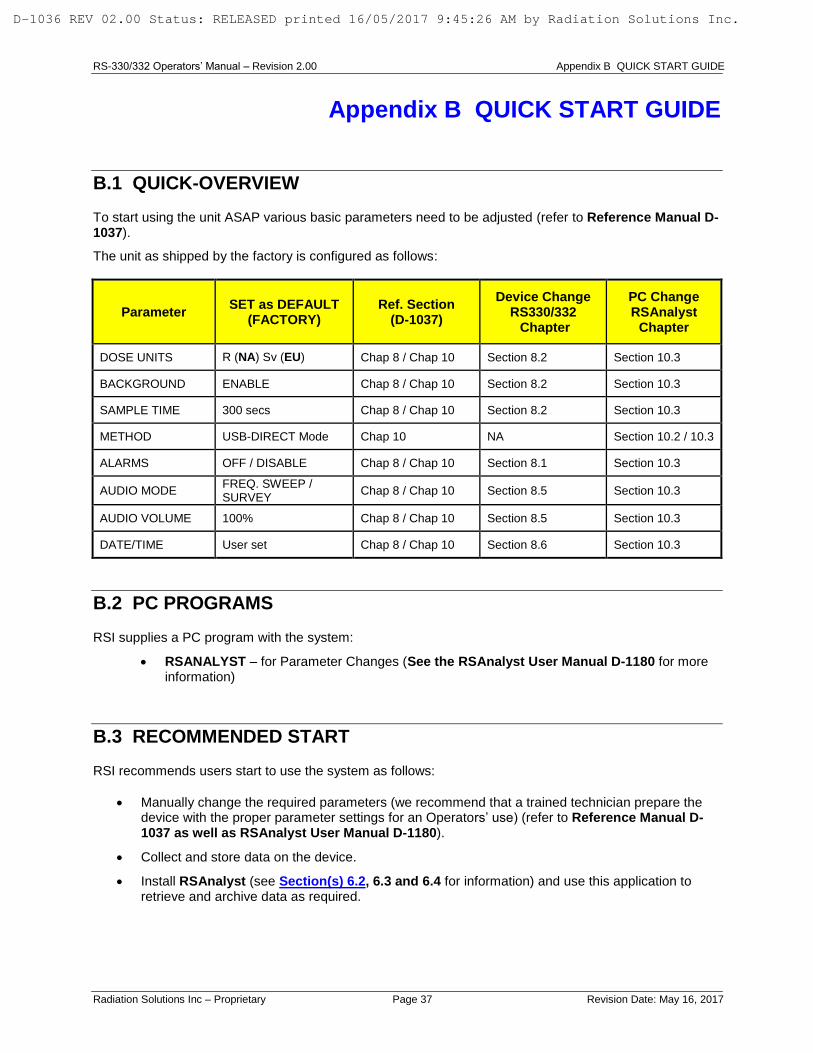
Appendix B QUICK START GUIDE
B.1 QUICK-OVERVIEW
To start using the unit ASAP various basic parameters need to be adjusted (refer to Reference Manual D-1037).
The unit as shipped by the factory is configured as follows:
Parameter SET as DEFAULT
(FACTORY) Ref. Section
(D-1037)
Device Change RS330/332 Chapter
PC Change RSAnalyst
Chapter
DOSE UNITS R (NA) Sv (EU) Chap 8 / Chap 10 Section 8.2 Section 10.3
BACKGROUND ENABLE Chap 8 / Chap 10 Section 8.2 Section 10.3
SAMPLE TIME 300 secs Chap 8 / Chap 10 Section 8.2 Section 10.3
METHOD USB-DIRECT Mode Chap 10 NA Section 10.2 / 10.3
ALARMS OFF / DISABLE Chap 8 / Chap 10 Section 8.1 Section 10.3
AUDIO MODE FREQ. SWEEP / SURVEY
Chap 8 / Chap 10 Section 8.5 Section 10.3
AUDIO VOLUME 100% Chap 8 / Chap 10 Section 8.5 Section 10.3
DATE/TIME User set Chap 8 / Chap 10 Section 8.6 Section 10.3
B.2 PC PROGRAMS
RSI supplies a PC program with the system:
RSANALYST – for Parameter Changes (See the RSAnalyst User Manual D-1180 for more information)
B.3 RECOMMENDED START
RSI recommends users start to use the system as follows:
Manually change the required parameters (we recommend that a trained technician prepare the device with the proper parameter settings for an Operators’ use) (refer to Reference Manual D-1037 as well as RSAnalyst User Manual D-1180).
Collect and store data on the device.
Install RSAnalyst (see Section(s) 6.2, 6.3 and 6.4 for information) and use this application to retrieve and archive data as required.
D-1036 REV 02.00 Status: RELEASED printed 16/05/2017 9:45:26 AM by Radiation Solutions Inc.

RS-330/332 Operators’ Manual – Revision 2.00 Appendix B QUICK START GUIDE
Radiation Solutions Inc – Proprietary Page 38 Revision Date: May 16, 2017
This Page is intentionally left Blank.
D-1036 REV 02.00 Status: RELEASED printed 16/05/2017 9:45:26 AM by Radiation Solutions Inc.

RS-330/332 Operators’ Manual – Revision 2.00 Appendix Z WARRANTY
Radiation Solutions Inc – Proprietary Page 39 Revision Date: May 16, 2017
Appendix Z WARRANTY
Radiation Solutions Inc Warranty The RS-330 is a delicate instrument and contains components (Crystal, Photomultiplier) which are very shock sensitive. The detector assembly is not covered under warranty. Manufacturer warrants to the original purchaser of Equipment that for the Warranty period, the Equipment will be free from material defects in material and workmanship.
a) The “Warranty Period” begins on the date the Equipment is delivered and continues for 12 months.
b) Any repairs under this warranty must be conducted by an authorized company service representative.
Excluded from the warranty are problems due to accidents, misuse, misapplication, storage damage, negligence, or modification to the Equipment or its components
Repairs of defects will be performed by RSI at no charge to the Buyer, subject to the limitations. To request warranty service, the Buyer must call RSI’s service coordinator for a return material authorization (RMA) number.
The Buyer is responsible for all the shipping, customs clearance costs and risk of loss of returning the repaired or replaced Products to the Buyer. RSI will own all parts removed from repaired Products or all Products replaced.
RSI’s warranty does not include breakage of the crystal for any reason. RSI does warrant the detectors to be complete and fully operational to their published specifications at the time of delivery and to maintain the minimum resolution and performance for a period of one year under normal operating condition.
Complete details of the “Standard Terms and Conditions” may be obtained by contacting RSI. For more information or to make a warranty claim contact RSI.
Contact Information Phone: (905) 890-1111 Fax: (905) 890-1964 Email: [email protected] [email protected]
D-1036 REV 02.00 Status: RELEASED printed 16/05/2017 9:45:26 AM by Radiation Solutions Inc.


![Supporting Online Material FINAL - Keio University · Supporting Online Material Materials and methods Inter-strand ligation assay 1.11 MBq [5’-32P]cytidine-3’,5’-bisphosphate](https://img.pdfslide.us/doc/110x75/5e0af26088a53f040d03ce9c/supporting-online-material-final-keio-supporting-online-material-materials-and.jpg)


![2008 JMPR Evaluations-- PART I€¦ · MBq/mg [Azaspirodecenyl-5-14 C]-cis-BYI 08330, radiochemical purity 98%, specific radioactivity 4.03 MBq/mg BYI 08330 is hydrolytically labile](https://img.pdfslide.us/doc/110x75/604c4ff5e7ae292c7a0aac3f/2008-jmpr-evaluations-part-i-mbqmg-azaspirodecenyl-5-14-c-cis-byi-08330-radiochemical.jpg)