Embed Size (px)
Citation preview

INSTALLATION MANUAL
BK-1200P
OPERATOR FOR SLIDING GATES
FA00605-EN
EnglishEN
p. 2
- M
anual
: FA
00
60
5-E
NFA
00
60
5-E
N v
. 1
- 01/
2017
- ©
CA
ME
S.p
.A. -
The
cont
ents
of
this
man
ual
may
be
chan
ged
, at
any
tim
e, a
nd
with
out
not
ice.
PREMISE
• THIS PRODUCT SHOULD ONLY BE USED FOR THE PURPOSE FOR WHICH IT WAS EXPLICITLY DESIGNED. ANY OTHER USE IS DANGEROUS. CAME S.P.A. IS NOT LIABLE FOR ANY DAMAGE CAUSED BYIMPROPER, WRONGFUL AND UNREASONABLE USE • KEEP THESE WARNINGS TOGETHER WITH THE INSTALLATION AND OPERATION MANUALS THAT COME WITH THE OPERATOR.
BEFORE INSTALLING
(CHECKING WHAT'S THERE: IF SOMETHING IS MISSING, DO NOT CONTINUE UNTIL YOU HAVE COMPLIED WITH ALL SAFETY PROVISIONS)
• CHECK THAT THE AUTOMATED PARTS ARE IN PROPER MECHANICAL ORDER, THAT THE OPERATOR IS LEVEL AND ALIGNED, AND THAT IT OPENS AND CLOSES PROPERLY. MAKE SURE YOU HAVE SUITABLE MECHANICAL STOPS • IF THE OPERATOR IS TO BE INSTALLED AT A HEIGHT OF LESS THAN 2.5 M FROM THE GROUND OR OTHER ACCESS LEVEL, MAKE SURE YOU HAVE ANY NECESSARY PROTECTIONS AND/OR WARNINGS IN PLACE • IF ANY PEDESTRIAN OPENINGS ARE FITTED INTO THE OPERATOR, THERE MUST ALSO BE A A SYSTEM TO BLOCK THEIR OPENING WHILE THEY ARE MOVING • MAKE SURE THAT THE OPENING AUTOMATED DOOR OR GATE CANNOT ENTRAP PEOPLE AGAINST THE FIXED PARTS OF THE OPERATOR • DO NOT FIT UPSIDE DOWN OR ONTO ELEMENTS THAT COULD BEND. IF NECESSARY, ADD SUITABLE REINFORCEMENTS TO THE ANCHORING POINTS • DO NOT INSTALL DOOR OR GATE LEAVES ON TILTED SURFACES • MAKE SURE ANY SPRINKLER SYSTEMS CANNOT WET THE OPERATOR FROM THE GROUND UP • MAKE SURE THE TEMPERATURE RANGE SHOWN ON THE PRODUCT LITERATURE IS SUITABLE TO THE CLIMATE WHERE IT WILL BE INSTALLED • FOLLOW ALL INSTRUCTIONS AS IMPROPER INSTALLATION MAY RESULT IN SERIOUS BODILY INJURY • IT IS IMPORTANT TO FOLLOW THESE INSTRUCTIONS FOR THE SAFETY OF PEOPLE. KEEP THESE INSTRUCTIONS.
INSTALLING
• SUITABLY SECTION OFF AND DEMARCATE THE ENTIRE INSTALLATION SITE TO PREVENT UNAUTHORIZED PERSONS FROM ENTERING THE AREA, ESPECIALLY MINORS AND CHILDREN • BE CAREFUL WHEN HANDLING OPERATORS THAT WEIGH OVER 20 KG. IF NEED BE, USE PROPER SAFETY HOISTING EQUIPMENT • ALL OPENING COMMANDS (THAT IS, BUTTONS, KEY SWITCHES, MAGNETIC READERS, AND SO ON) MUST BE INSTALLED AT LEAST 1.85 M FROM THE PERIMETER OF THE GATE'S WORKING AREA, OR WHERE THEY CANNOT BE REACHED FROM OUTSIDE THE GATE. ALSO, ANY DIRECT COMMANDS (WHETHER BUTTONS, TOUCH PANELS, AND SO ON) MUST BE INSTALLED AT LEAST 1.5 M FROM THE GROUND AND MUST NOT BE REACHABLE BY UNAUTHORIZED PERSONS • ALL MAINTAINED ACTION COMMANDS, MUST BE FITTED IN PLACES FROM WHICH THE MOVING GATE LEAVES AND TRANSIT AND DRIVING AREAS ARE VISIBLE • APPLY, IF MISSING, A PERMANENT SIGN SHOWING THE POSITION OF THE RELEASE DEVICE • BEFORE DELIVERING TO THE USERS, MAKE SURE THE SYSTEM IS EN 12453 STANDARD COMPLIANT (REGARDING IMPACT FORCES), AND ALSO MAKE SURE THE SYSTEM HAS BEEN PROPERLY ADJUSTED AND THAT ANY SAFETY, PROTECTION AND MANUAL RELEASE DEVICES ARE WORKING PROPERLY • APPLY WARNING SIGNS WHERE NECESSARY AND IN A VISIBLE PLACE, (SUCH AS, SUCH AS THE GATE'S PLATE
SPECIAL USER-INSTRUCTIONS AND RECOMMENDATIONS
• KEEP GATE OPERATION AREAS CLEAN AND FREE OF ANY OBSTRUCTIONS. MAKE SURE THAT THE PHOTOCELLS ARE FREE OF ANY OVERGROWN VEGETATION AND THAT THE OPERATOR'S AREA OF OPERATION IS FREE OF ANY OBSTRUCTIONS • DO NOT ALLOW CHILDREN TO PLAY WITH FIXED COMMANDS, OR TO LOITER IN THE GATE'S MANEUVERING AREA. KEEP ANY REMOTE CONTROL TRANSMITTERS OR ANY OTHER COMMAND DEVICE AWAY FROM CHILDREN, TO PREVENT THE OPERATOR FROM BEING ACCIDENTALLY ACTIVATED. • THE APPARATUS MAY BE USED BY CHILDREN OF EIGHT YEARS AND ABOVE AND BY PHYSICALLY, MENTALLY AND SENSORY-CHALLENGED PEOPLE, OR EVEN ONES WITHOUT ANY EXPERIENCE, PROVIDED THIS HAPPENS UNDER CLOSE SUPERVISION OR ONCE THEY HAVE BEEN PROPERLY INSTRUCTED TO USE THE APPARATUS SAFELY AND TO THE POTENTIAL HAZARDS INVOLVED. CHILDREN MUST NOT PLAY WITH THE APPARATUS. CLEANING AND MAINTENANCE BY USERS MUST NOT BE DONE BY CHILDREN, UNLESS PROPERLY SUPERVISED • FREQUENTLY CHECK THE SYSTEM FOR ANY MALFUNCTIONS OR SIGNS OF WEAR AND TEAR OR DAMAGE TO THE MOVING STRUCTURES, TO THE COMPONENT PARTS, ALL ANCHORING POINTS, INCLUDING CABLES AND ANY ACCESSIBLE CONNECTIONS. KEEP ANY HINGES, MOVING JOINTS AND SLIDE RAILS PROPERLY LUBRICATED • PERFORM FUNCTIONAL CHECKS ON THE PHOTOCELLS AND SENSITIVE SAFETY EDGES, EVERY SIX MONTHS. TO CHECK WHETHER THE PHOTOCELLS ARE WORKING, WAVE AN OBJECT IN FRONT OF THEM
WHILE THE GATE IS CLOSING; IF THE OPERATOR INVERTS ITS DIRECTION OF TRAVEL OR SUDDENLY STOPS, THE PHOTOCELLS ARE WORKING PROPERLY. THIS IS THE ONLY MAINTENANCE OPERATION TO DO WITH THE POWER ON. CONSTANTLY CLEAN THE PHOTOCELLS' GLASS COVERS USING A SLIGHTLY WATER-MOISTENED CLOTH; DO NOT USE SOLVENTS OR OTHER CHEMICAL PRODUCTS THAT MAY RUIN THE DEVICES • IF REPAIRS OR MODIFICATIONS ARE REQUIRED TO THE SYSTEM, RELEASE THE OPERATOR AND DO NOT USE IT UNTIL SAFETY CONDITIONS HAVE BEEN RESTORED • CUT OFF THE POWER SUPPLY BEFORE RELEASING THE OPERATOR FOR MANUAL OPENINGS AND BEFORE ANY OTHER OPERATION, TO PREVENT POTENTIALLY HAZARDOUS SITUATIONS. READ THE INSTRUCTIONS IF THE POWER SUPPLY CABLE IS DAMAGED, IT MUST BE REPLACED BY THE MANUFACTURER OR AUTHORIZED TECHNICAL ASSISTANCE SERVICE, OR IN ANY CASE, BY SIMILARLY QUALIFIED PERSONS, TO PREVENT ANY RISK • IT IS FORBIDDEN FOR USERS TO PERFORM ANY OPERATIONS THAT ARE NOT EXPRESSLY REQUIRED OF THEM AND WHICH ARE NOT LISTED IN THE MANUALS. FOR ANY REPAIRS, MODIFICATIONS / ADJUSTMENTS, AND FOR EXTRA-ORDINARY MAINTENANCE, CALL TECHNICAL ASSISTANCE • LOG THE JOB AND CHECKS INTO THE PERIODIC MAINTENANCE LOG.
FURTHER RECOMMENDATIONS FOR ALL
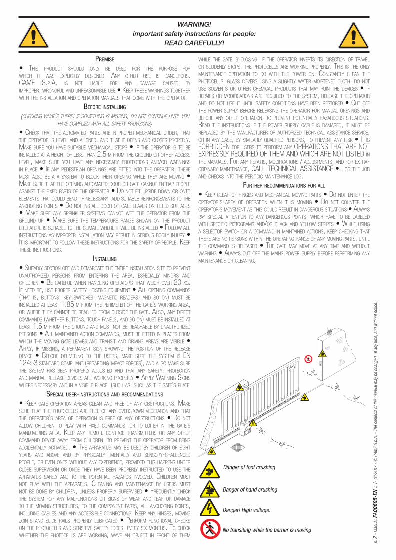
• KEEP CLEAR OF HINGES AND MECHANICAL MOVING PARTS • DO NOT ENTER THE OPERATOR'S AREA OF OPERATION WHEN IT IS MOVING • DO NOT COUNTER THE OPERATOR'S MOVEMENT AS THIS COULD RESULT IN DANGEROUS SITUATIONS • ALWAYS PAY SPECIAL ATTENTION TO ANY DANGEROUS POINTS, WHICH HAVE TO BE LABELED WITH SPECIFIC PICTOGRAMS AND/OR BLACK AND YELLOW STRIPES • WHILE USING A SELECTOR SWITCH OR A COMMAND IN MAINTAINED ACTIONS, KEEP CHECKING THAT THERE ARE NO PERSONS WITHIN THE OPERATING RANGE OF ANY MOVING PARTS, UNTIL THE COMMAND IS RELEASED • THE GATE MAY MOVE AT ANY TIME AND WITHOUT WARNING • ALWAYS CUT OFF THE MAINS POWER SUPPLY BEFORE PERFORMING ANY MAINTENANCE OR CLEANING.
WARNING!important safety instructions for people:
READ CAREFULLY!
Danger of hand crushing
Danger! High voltage.
No transiting while the barrier is moving
Danger of foot crushing

360
105
22 m
ax.
182,5 142,5
325
170
255
106
15
p. 3
- M
anual
: FA
00
60
5-E
NFA
00
60
5-E
N v
. 1
- 01/
2017
- ©
CA
ME
S.p
.A.
- Th
e m
anual
's c
onte
nts
may
be
edite
d at
any
tim
e w
ithou
t not
ice.
Dimensions (mm)
DESCRIPTION
Operator featuring control board, mechanical limit-switches and PRATICO SYSTEM radio releasing system which comes with its own 12 V - 1.2 Ah battery for sliding gates weighing up to 1,200 kg in weight and measuring 14 m in length.
The BK-1200P is designed to power sliding gates in single homes and apartment blocks alike.
Any installation and/or use other than that specifi ed in this manual is forbidden.
Limits to use
Type BK-1200PMax gate-leaf weight (kg) 1,200
Maximum door-leaf length (m) 14
Pinion module 4
This symbol shows which parts to read carefully.
⚠ This symbol shows which parts describe safety issues
☞ This symbol shows which parts to tell users about.
LEGEND
Intended use
Technical data
Type BK-1200PProtection rating (IP) 44
Power supply (V - 50/60 Hz) 230 AC
Power supply to motor (V - 50/60 Hz) 230 AC
Stand-by consumption (W) 3.3
Power (W) 380
Thrust (N) 850
Opening speed (m/min) 14.5
Duty cycle (%) 30
Operating temperature (°C) -20 ÷ +55
Condenser (μF) 31.5
Apparatus class I
Motor's heat protection (°C) 150
Weight (Kg) 18

CAME
p. 4
- M
anual
: FA
00
60
5-E
NFA
00
60
5-E
N v
. 1
- 01/
2017
- ©
CA
ME
S.p
.A. -
The
cont
ents
of
this
man
ual
may
be
chan
ged
, at
any
tim
e, a
nd
with
out
not
ice.
Description of parts
1. Cover
2. Gearmotor
3. Control board
4. Front cover
5. Anchoring plate
6. Control-board holder
7. Limit-switch fins
8. Mechanical limit switch
9. Fan
10. Transformer
11. Release hatch
12. Release key
Standard installation
1. Operator
2. Limit-switch fins
3. Rack
4. Key-switch selector
5. Flashing light
6. Antenna
7. Photocells
8. Photocells post
9. Mechanical gate stop
10. Sensitive safety-edge
11. Junction pit
300
500
450
p. 5
- M
anual
: FA
00
60
5-E
NFA
00
60
5-E
N v
. 1
- 01/
2017
- ©
CA
ME
S.p
.A.
- Th
e m
anual
's c
onte
nts
may
be
edite
d at
any
tim
e w
ithou
t not
ice.
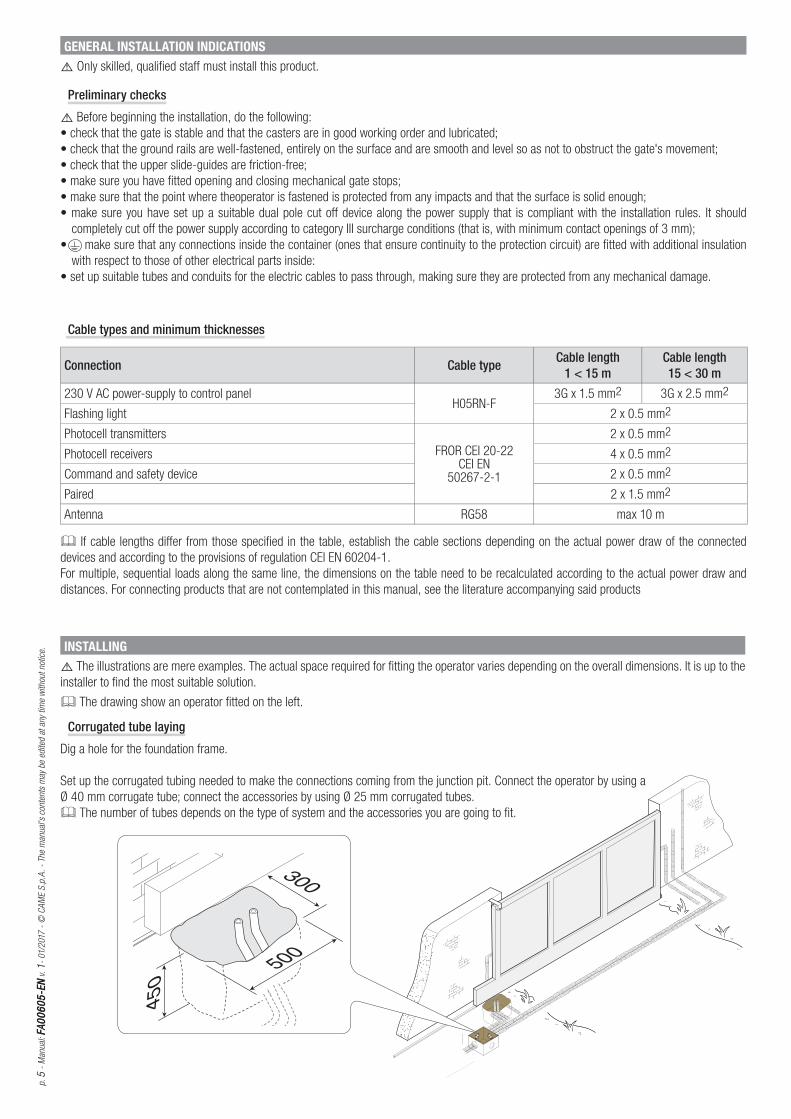
GENERAL INSTALLATION INDICATIONS
⚠ Only skilled, qualified staff must install this product.
Preliminary checks
⚠ Before beginning the installation, do the following:
• check that the gate is stable and that the casters are in good working order and lubricated;
• check that the ground rails are well-fastened, entirely on the surface and are smooth and level so as not to obstruct the gate's movement;
• check that the upper slide-guides are friction-free;
• make sure you have fitted opening and closing mechanical gate stops;
• make sure that the point where theoperator is fastened is protected from any impacts and that the surface is solid enough;
• make sure you have set up a suitable dual pole cut off device along the power supply that is compliant with the installation rules. It should
completely cut off the power supply according to category III surcharge conditions (that is, with minimum contact openings of 3 mm);
• make sure that any connections inside the container (ones that ensure continuity to the protection circuit) are fitted with additional insulation
with respect to those of other electrical parts inside:
• set up suitable tubes and conduits for the electric cables to pass through, making sure they are protected from any mechanical damage.
Cable types and minimum thicknesses
Connection Cable type Cable length1 < 15 m
Cable length15 < 30 m
230 V AC power-supply to control panelH05RN-F
3G x 1.5 mm2 3G x 2.5 mm2
Flashing light 2 x 0.5 mm2
Photocell transmitters
FROR CEI 20-22 CEI EN
50267-2-1
2 x 0.5 mm2
Photocell receivers 4 x 0.5 mm2
Command and safety device 2 x 0.5 mm2
Paired 2 x 1.5 mm2
Antenna RG58 max 10 m
If cable lengths diff er from those specifi ed in the table, establish the cable sections depending on the actual power draw of the connected
devices and according to the provisions of regulation CEI EN 60204-1.
For multiple, sequential loads along the same line, the dimensions on the table need to be recalculated according to the actual power draw and
distances. For connecting products that are not contemplated in this manual, see the literature accompanying said products
INSTALLING
⚠ The illustrations are mere examples. The actual space required for fitting the operator varies depending on the overall dimensions. It is up to the
installer to find the most suitable solution.
The drawing show an operator fitted on the left.
Corrugated tube laying
Dig a hole for the foundation frame.
Set up the corrugated tubing needed to make the connections coming from the junction pit. Connect the operator by using a
Ø 40 mm corrugate tube; connect the accessories by using Ø 25 mm corrugated tubes.
The number of tubes depends on the type of system and the accessories you are going to fit.

2
1
50
84
105
p. 6
- M
anual
: FA
00
60
5-E
NFA
00
60
5-E
N v
. 1
- 01/
2017
- ©
CA
ME
S.p
.A. -
The
cont
ents
of
this
man
ual
may
be
chan
ged
, at
any
tim
e, a
nd
with
out
not
ice.
Laying the anchoring plate
Set up a foundation frame that is larger than the anchoring plate and sink it into the dug hole. The foundation frame must jut out by 50 mm above
ground level.
Fit an iron cage into the foundation frame to reinforce the concrete.
Fit the bolts into the fastening plate and tighten them using the nuts. Remove the pre-shaped clamps using a screw driver or pliers.
If the rack is already there, place the anchoring plate, being careful to respect the measurements shown in the drawing.
⚠ Careful! The tubes must pass through their corresponding holes.
Fill the foundation frame with concrete. The plate must be perfectly level with the bolts which are entirely above surface.
Wait at least 24 hours, for it to solidify.
Remove the foundation frame and fill the hole with earth around the concrete block.
5 ÷
10
p. 7
- M
anual
: FA
00
60
5-E
NFA
00
60
5-E
N v
. 1
- 01/
2017
- ©
CA
ME
S.p
.A.
- Th
e m
anual
's c
onte
nts
may
be
edite
d at
any
tim
e w
ithou
t not
ice.
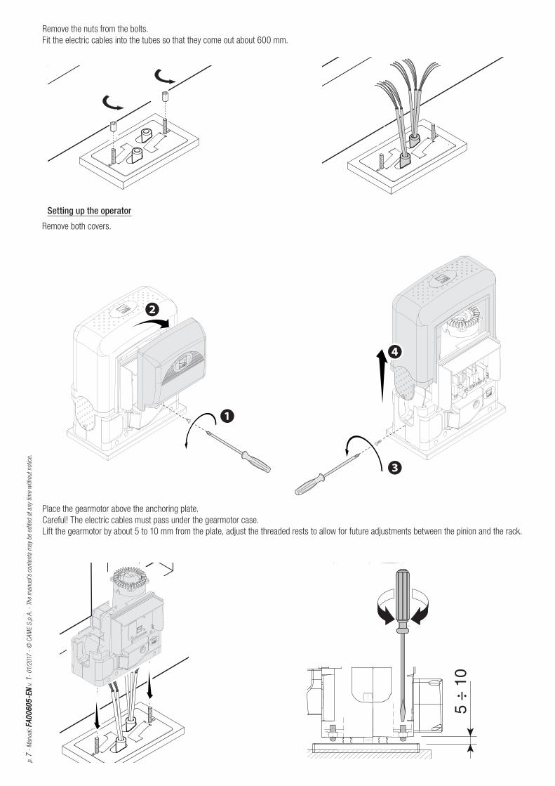
Remove the nuts from the bolts.
Fit the electric cables into the tubes so that they come out about 600 mm.
Setting up the operator
Remove both covers.
Place the gearmotor above the anchoring plate.
Careful! The electric cables must pass under the gearmotor case.
Lift the gearmotor by about 5 to 10 mm from the plate, adjust the threaded rests to allow for future adjustments between the pinion and the rack.
1 ÷
2
p. 8
- M
anual
: FA
00
60
5-E
NFA
00
60
5-E
N v
. 1
- 01/
2017
- ©
CA
ME
S.p
.A. -
The
cont
ents
of
this
man
ual
may
be
chan
ged
, at
any
tim
e, a
nd
with
out
not
ice.
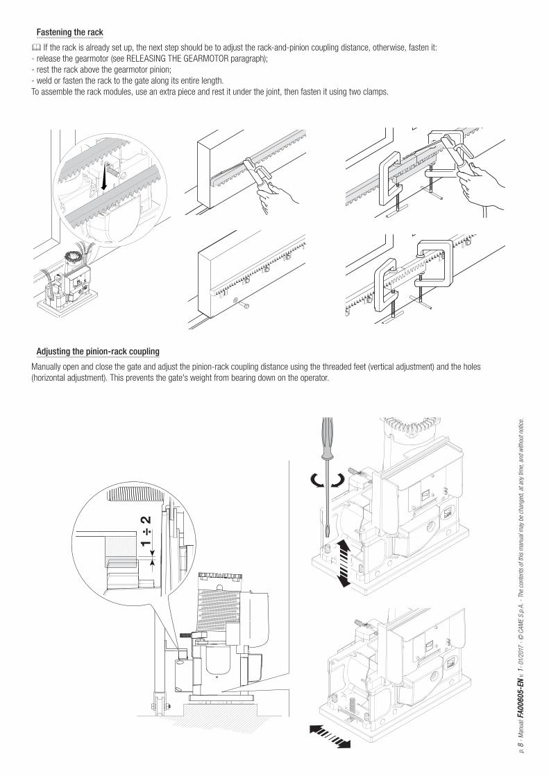
Fastening the rack
If the rack is already set up, the next step should be to adjust the rack-and-pinion coupling distance, otherwise, fasten it:
- release the gearmotor (see RELEASING THE GEARMOTOR paragraph);
- rest the rack above the gearmotor pinion;
- weld or fasten the rack to the gate along its entire length.
To assemble the rack modules, use an extra piece and rest it under the joint, then fasten it using two clamps.
Adjusting the pinion-rack coupling
Manually open and close the gate and adjust the pinion-rack coupling distance using the threaded feet (vertical adjustment) and the holes
(horizontal adjustment). This prevents the gate's weight from bearing down on the operator.

1
2
22
1
p. 9
- M
anual
: FA
00
60
5-E
NFA
00
60
5-E
N v
. 1
- 01/
2017
- ©
CA
ME
S.p
.A.
- Th
e m
anual
's c
onte
nts
may
be
edite
d at
any
tim
e w
ithou
t not
ice.
Fastening the gearmotor
Once adjusting is complete, fasten the gearmotor to the plate using the plates and nuts.
Establishing the limit-switch points
For opening:
- open the gate ;
- fi t the opening limit-switch tab onto the rack until the micro switch activates (spring) and fasten it using the grub screws .
Spring
~ 20 mm
For closing:
- close the gate ;
- fi t the closing limit-switch fi n into the rack until the micro-switch is activated (spring) and fasten it using the grub screws .
~ 20 mm

LINE FUSE
ON
2 1 3 4 5 6 7 8 9 10
L1T L2T CT VS VF U V W E1 L N 24 12 0 10 11 TS 1 2 3 3P 4 7 C1 C3 EB EB FC FA F
+ A. C.T. - + PAR.OP -
ELECTRIC BLOCK
1.6A
BOARD 315mA
ACCESSORIES 1A
BATTERY 1.6A
CONTROL BOARD
ZBK8
AF1
AF2
CH1
- +
18
5
12
14
1
16
6 7 4 8 9
10
11
17
15
3
13
2
p. 1
01
0 -
Man
ual
: FA
00
60
5-E
NFA
00
60
5-E
N v
. 1
- 01/
2017
- ©
CA
ME
S.p
.A. -
The
cont
ents
of
this
man
ual
may
be
chan
ged
, at
any
tim
e, a
nd
with
out
not
ice.
Description of parts
1. Terminals for connecting to
the power supply and the
transformer
2. Line fuse 8 A
3. Accessories fuse 1 A
4. DIP-switch "selecting functions”
5. Radio-frequency card slot for
remote control
6. A.C.T. Trimmer: adjusting the
automatic closing time
7. PAR.OP Trimmer .: adjusting
partial opening
8. Code-memorizing button on the
radio remote-control
9. Radio remote-control code
signaling LED
10. Battery-connection terminal
11. Radio frequency card slot for
Pratico System
12. Battery fuse 1.6 A
13. Control unit fuse 315 mA
14. Electric lock fuse 1.6 A
15. Signal LEDs 230 V
16. Electric lock, limit switch and
accessory connection terminals
17. PRATICO SYSTEM radio code
signal LED
18. Button for memorizing the
PRATICO SYSTEM radio code
ZBK8 TECHNICAL DATAPower supply voltage 230 V - 50/60 Hz
Absorption when idle 38 mA
Accessories' maximum power load 24 V 40 W
Circuits insulation class II
ZBK8 FUSE TABLEto protect: fuse rated:
Control board (line) 8 A-F
Accessories 1 A-F
Control devices (control unit) 315 mA-F
Electroblock 1.6 A-F
Batteries 1.6 A-F
ELECTRICAL CONNECTIONS
⚠ Warning! Before doing any work on the control board, cut off the mains power supply, and disconnect any batteries.
Power supply to the control panel and control devices: 24 V AC/DC.
Use DIP switches to set functions and the trimmer for adjustments.
All connections are quick-fuse protected.
⚠ The operator is designed to be fitted on the left. If installing on the right, invert the gearmotor's U-V and the limit-switches FA-FC cables.
COM
NC
NC
COM
COM
NC
NC
COM
COM
p. 1
111 -
Man
ual
: FA
00
60
5-E
NFA
00
60
5-E
N v
. 1
- 01/
2017
- ©
CA
ME
S.p
.A.
- Th
e m
anual
's c
onte
nts
may
be
edite
d at
any
tim
e w
ithou
t not
ice.
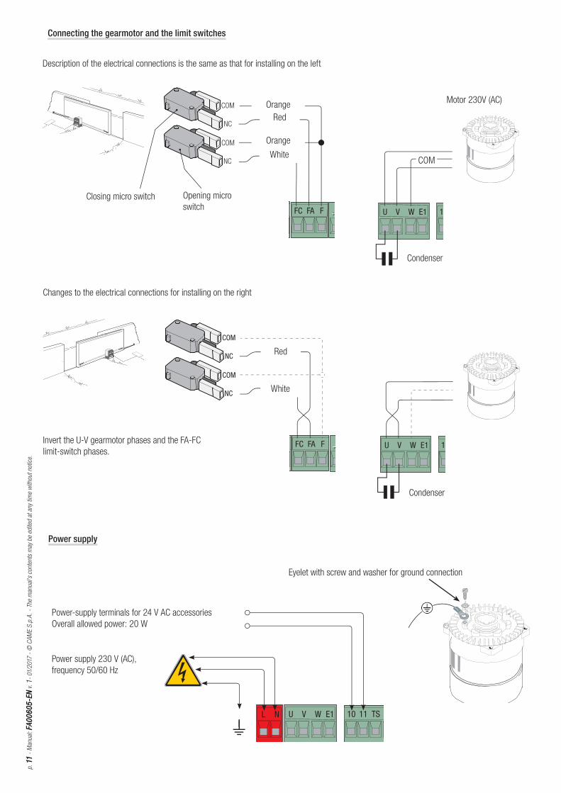
Power supply
Power-supply terminals for 24 V AC accessories
Overall allowed power: 20 W
Power supply 230 V (AC),
frequency 50/60 Hz
Eyelet with screw and washer for ground connection
Closing micro switch
Changes to the electrical connections for installing on the right
Invert the U-V gearmotor phases and the FA-FC
limit-switch phases.
Opening micro
switch
Description of the electrical connections is the same as that for installing on the left
Condenser
Motor 230V (AC)Orange
Orange
Red
Red
White
White
Connecting the gearmotor and the limit switches
Condenser
p. 1
21
2 -
Man
ual
: FA
00
60
5-E
NFA
00
60
5-E
N v
. 1
- 01/
2017
- ©
CA
ME
S.p
.A. -
The
cont
ents
of
this
man
ual
may
be
chan
ged
, at
any
tim
e, a
nd
with
out
not
ice.
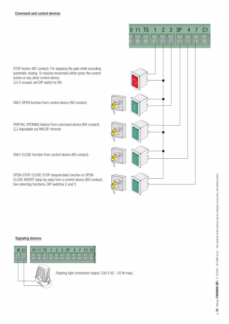
Command and control devices
STOP button (NC contact). For stopping the gate while excluding
automatic closing. To resume movement either press the control
button or any other control device.
If unused, set DIP switch to ON.
ONLY OPEN function from control device (NO contact)
OPEN-STOP-CLOSE-STOP (sequenziale) function or OPEN-
CLOSE-INVERT (step-by-step) from a control device (NO contact).
See selecting functions, DIP switches 2 and 3.
PARTIAL OPENING feature from command device (NO contact).
Adjustable via PAR.OP. trimmer.
ONLY CLOSE function from control device (NO contact)
Signaling devices
Flashing light connection output: 230 V AC - 25 W max).
Dir/DeltaS
R XR X T XT X
FUSIBILE 200m A
2X
-+ -
Dir/DeltaSR XR X T XT X
R XR X T XT XDelta
Delta
R XR X T XT X
p. 1
31
3 -
Man
ual
: FA
00
60
5-E
NFA
00
60
5-E
N v
. 1
- 01/
2017
- ©
CA
ME
S.p
.A.
- Th
e m
anual
's c
onte
nts
may
be
edite
d at
any
tim
e w
ithou
t not
ice.
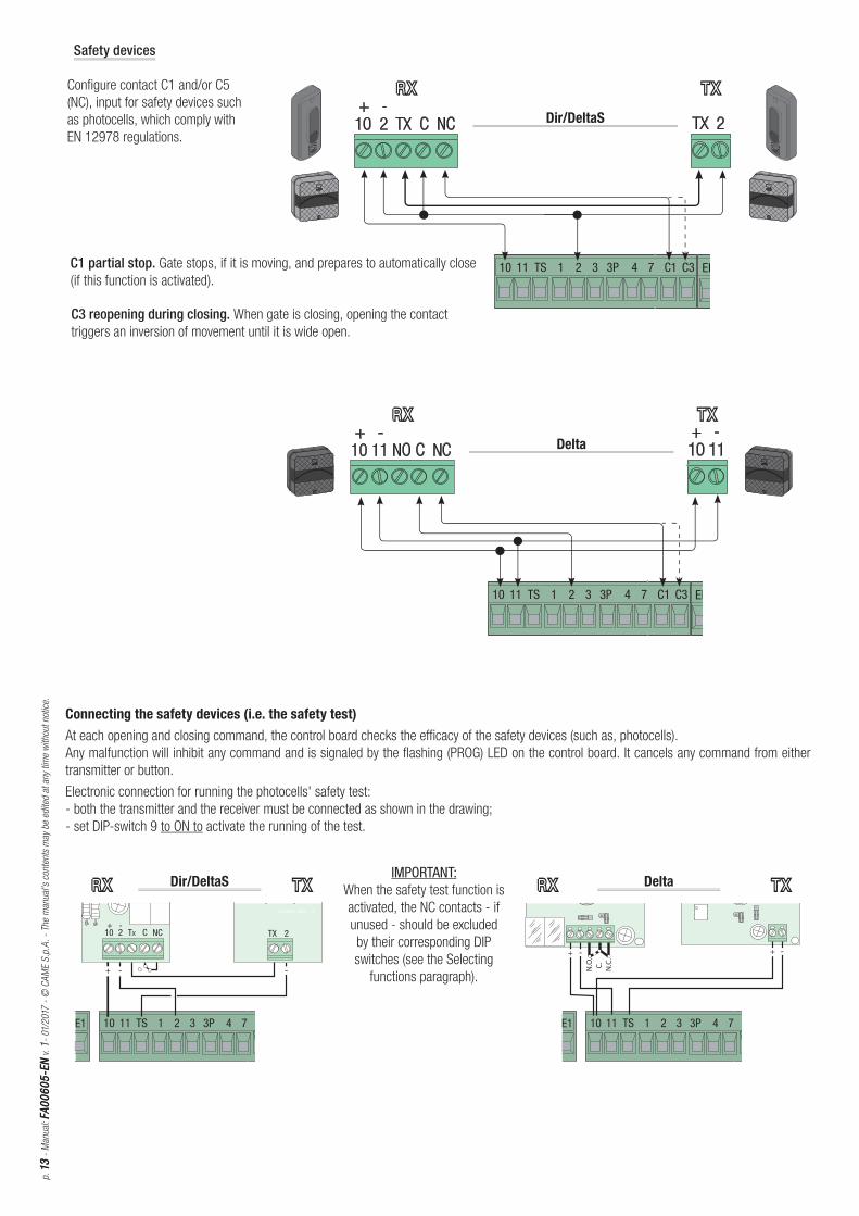
C1 partial stop. Gate stops, if it is moving, and prepares to automatically close
(if this function is activated).
Configure contact C1 and/or C5
(NC), input for safety devices such
as photocells, which comply with
EN 12978 regulations.
Safety devices
C3 reopening during closing. When gate is closing, opening the contact
triggers an inversion of movement until it is wide open.
IMPORTANT: When the safety test function is
activated, the NC contacts - if
unused - should be excluded
by their corresponding DIP
switches (see the Selecting
functions paragraph).
Connecting the safety devices (i.e. the safety test)
At each opening and closing command, the control board checks the effi cacy of the safety devices (such as, photocells).
Any malfunction will inhibit any command and is signaled by the fl ashing (PROG) LED on the control board. It cancels any command from either
transmitter or button.
Electronic connection for running the photocells' safety test:
- both the transmitter and the receiver must be connected as shown in the drawing;
- set DIP-switch 9 to ON to activate the running of the test.
LINE FUSE
ON
2 1 3 4 5 6 7 8 9 10
L1T L2T CT VS VF U V W E1 L N 24 12 0 10 11 TS 1 2 3 3P 4 7 C1 C3 EB EB FC FA F
+ A. C.T. - + PAR.OP -
ELECTRIC BLOCK
1.6A
BOARD 315mA
ACCESSORIES 1A
BATTERY 1.6A
CONTROL BOARD
ZBK8
AF1
AF2
CH1
- +
ON
OFF
LINE FUSE
ON
2 1 3 4 5 6 7 8 9 10
L1T L2T CT VS VF U V W E1 L N 24 12 0 10 11 TS 1 2 3 3P 4 7 C1 C3 EB EB FC FA F
+ A. C.T. - + PAR.OP -
ELECTRIC BLOCK
1.6A
BOARD 315mA
ACCESSORIES 1A
BATTERY 1.6A
CONTROL BOARD
ZBK8
AF1
AF2
CH1
- +
p. 1
414
- M
anual
: FA
00
60
5-E
NFA
00
60
5-E
N v
. 1
- 01/
2017
- ©
CA
ME
S.p
.A. -
The
cont
ents
of
this
man
ual
may
be
chan
ged
, at
any
tim
e, a
nd
with
out
not
ice.
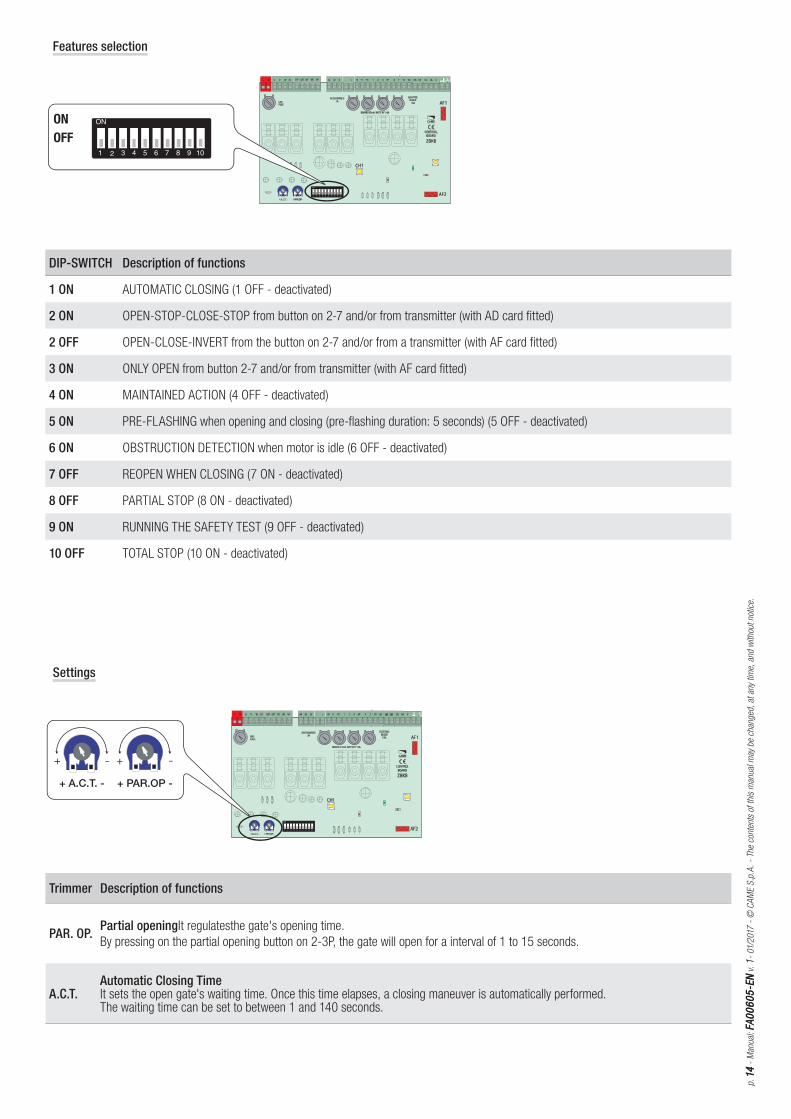
Features selection
Settings
Trimmer Description of functions
PAR. OP. Partial openingIt regulatesthe gate's opening time.
By pressing on the partial opening button on 2-3P, the gate will open for a interval of 1 to 15 seconds.
A.C.T.Automatic Closing TimeIt sets the open gate's waiting time. Once this time elapses, a closing maneuver is automatically performed.The waiting time can be set to between 1 and 140 seconds.
DIP-SWITCH Description of functions
1 ON AUTOMATIC CLOSING (1 OFF - deactivated)
2 ON OPEN-STOP-CLOSE-STOP from button on 2-7 and/or from transmitter (with AD card fitted)
2 OFF OPEN-CLOSE-INVERT from the button on 2-7 and/or from a transmitter (with AF card fitted)
3 ON ONLY OPEN from button 2-7 and/or from transmitter (with AF card fitted)
4 ON MAINTAINED ACTION (4 OFF - deactivated)
5 ON PRE-FLASHING when opening and closing (pre-flashing duration: 5 seconds) (5 OFF - deactivated)
6 ON OBSTRUCTION DETECTION when motor is idle (6 OFF - deactivated)
7 OFF REOPEN WHEN CLOSING (7 ON - deactivated)
8 OFF PARTIAL STOP (8 ON - deactivated)
9 ON RUNNING THE SAFETY TEST (9 OFF - deactivated)
10 OFF TOTAL STOP (10 ON - deactivated)
AF2
LINE FUSE
ON
21 3 4 5 6 7 8 9 10
L1T L2T CT VS VFU V W E1N 24 12 0 10 11 TS 1 2 3 3P 4 7 C1 C3 EB EB FC FA F
+ A. C. - + PAR.OP -
ELECTRICBLOCK
1.6A
BOARD 315mA
ACCESSORIES1A
BATTERY 1.6A
CONTROL BOARD
ZBK8
AF1
AF2
CH1
- +
AF2
H1
AF2
H1
p. 1
51
5 -
Man
ual
: FA
00
60
5-E
NFA
00
60
5-E
N v
. 1
- 01/
2017
- ©
CA
ME
S.p
.A.
- Th
e m
anual
's c
onte
nts
may
be
edite
d at
any
tim
e w
ithou
t not
ice.
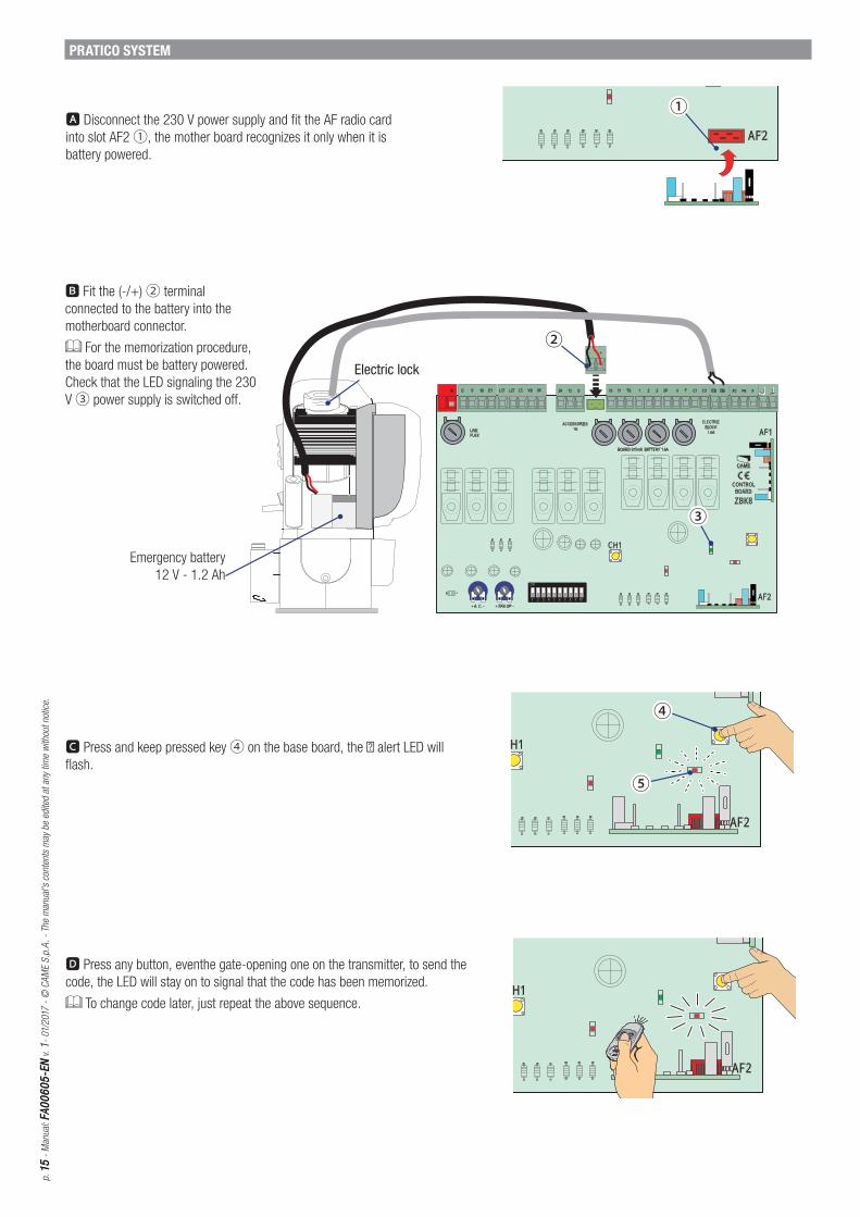
PRATICO SYSTEM
Emergency battery
12 V - 1.2 Ah
B Fit the (-/+) ② terminal
connected to the battery into the
motherboard connector.
For the memorization procedure,
the board must be battery powered.
Check that the LED signaling the 230
V ③ power supply is switched off .
A Disconnect the 230 V power supply and fi t the AF radio card
into slot AF2 ①, the mother board recognizes it only when it is
battery powered.
C Press and keep pressed key ④ on the base board, the � alert LED will
fl ash.
D Press any button, eventhe gate-opening one on the transmitter, to send the
code, the LED will stay on to signal that the code has been memorized.
To change code later, just repeat the above sequence.
Electric lock
FC FA F
CONTROL BOARD
AF1
FC FA F
CONTROL BOARD
AF1
CONTROL BOARD
ZBK8
AF1
AF2
CH1
C
Z
AF27 8 9 10
ACCESSORIES
CONTROL BOARD
ZBK8
AF1
AF2
CH1
7 8 9 10
ACCESSORIES
C
Z
AF2
4 7 FC FA F
ZBK8
AF1
4 7 FC FA F
Z
p. 1
61
6 -
Man
ual
: FA
00
60
5-E
NFA
00
60
5-E
N v
. 1
- 01/
2017
- ©
CA
ME
S.p
.A. -
The
cont
ents
of
this
man
ual
may
be
chan
ged
, at
any
tim
e, a
nd
with
out
not
ice.
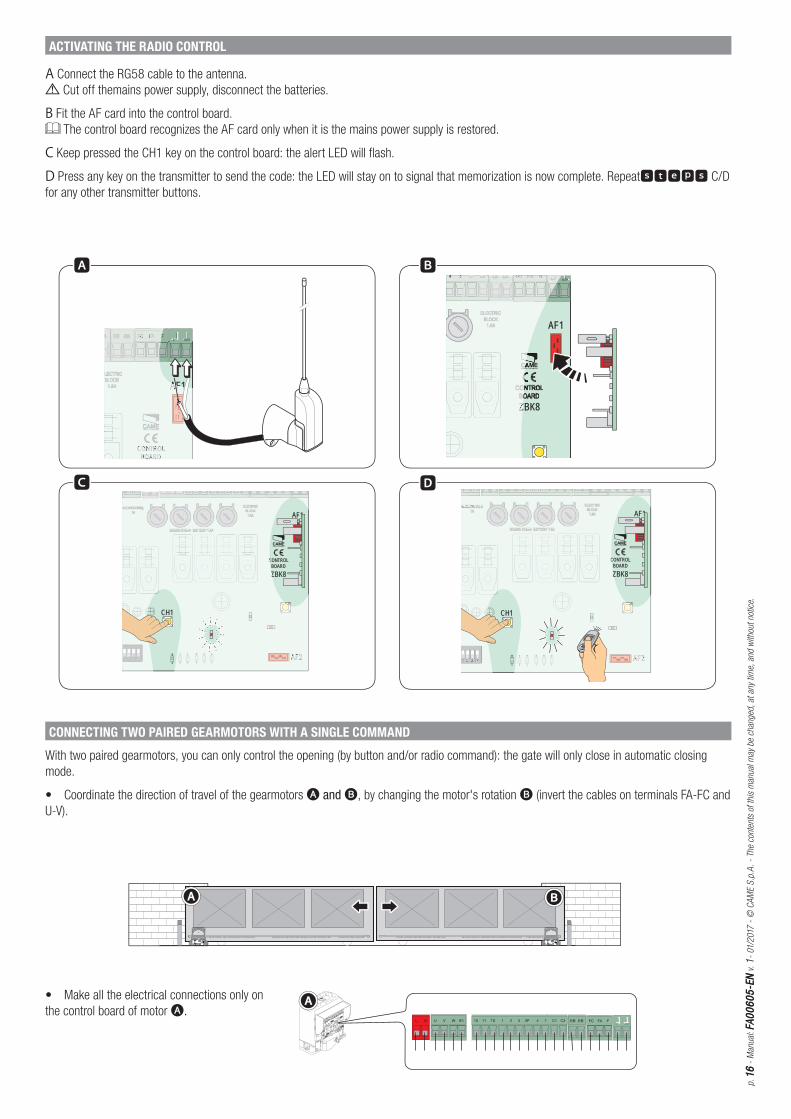
A Connect the RG58 cable to the antenna.
Cut off themains power supply, disconnect the batteries.
B Fit the AF card into the control board.
The control board recognizes the AF card only when it is the mains power supply is restored.
C Keep pressed the CH1 key on the control board: the alert LED will flash.
D Press any key on the transmitter to send the code: the LED will stay on to signal that memorization is now complete. Repeatsteps C/D
for any other transmitter buttons.
ACTIVATING THE RADIO CONTROL
• Make all the electrical connections only on
the control board of motor A.
CONNECTING TWO PAIRED GEARMOTORS WITH A SINGLE COMMAND
With two paired gearmotors, you can only control the opening (by button and/or radio command): the gate will only close in automatic closing
mode.
• Coordinate the direction of travel of the gearmotors A and B, by changing the motor's rotation B (invert the cables on terminals FA-FC and
U-V).

ON
2 1 3 4 5 6 7 8 9 10
+ A. C.T. - + PAR.OP -
AF2
CH1
+ A. C.T. + PAR.OP
CH1
p. 1
717 -
Man
ual
: FA
00
60
5-E
NFA
00
60
5-E
N v
. 1
- 01/
2017
- ©
CA
ME
S.p
.A.
- Th
e m
anual
's c
onte
nts
may
be
edite
d at
any
tim
e w
ithou
t not
ice.
• Set DIP switches 1 and 3 to ON; on both boards.
For opening with the radio command, connect an external receiver ((RExxx/RBExxx with relay switch in MONOSTABLE mode) to terminals 2-3
of gearmotor A.
• Connect the two control boards, as shown in the fi gure.
• Make the same adjustments and activate the same functions on both boards.
FINAL OPERATIONS
Do the fi nal operation only once the connections are complete and the system is started up.
1
1
1p.
18
18
- M
anual
: FA
00
60
5-E
NFA
00
60
5-E
N v
. 1
- 01/
2017
- ©
CA
ME
S.p
.A. -
The
cont
ents
of
this
man
ual
may
be
chan
ged
, at
any
tim
e, a
nd
with
out
not
ice.
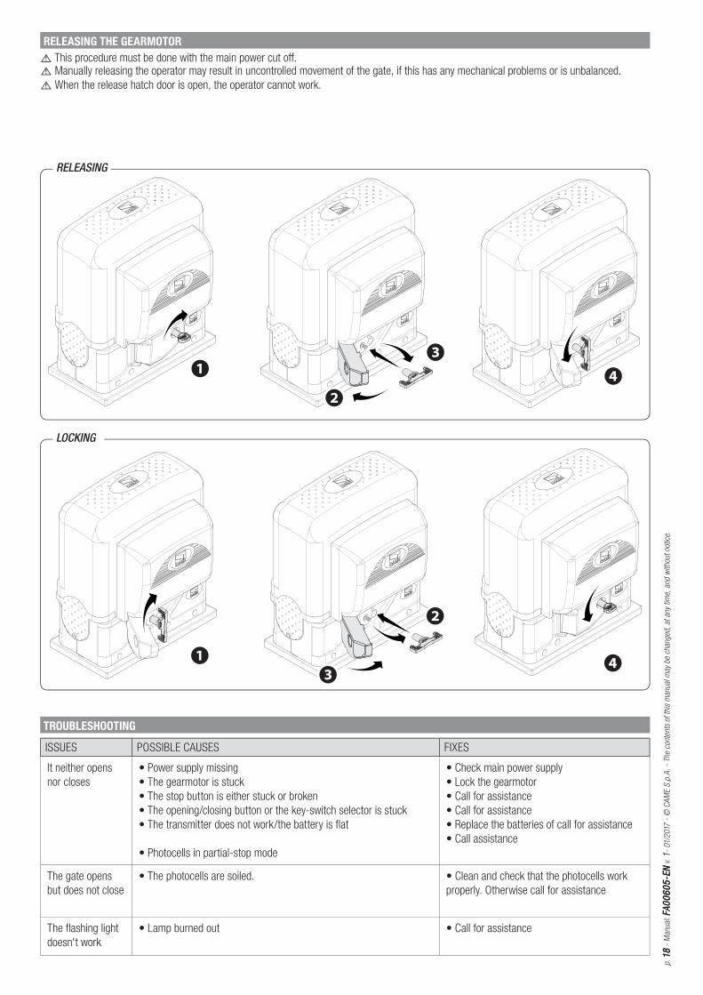
RELEASING THE GEARMOTOR
⚠ This procedure must be done with the main power cut off .
⚠ Manually releasing the operator may result in uncontrolled movement of the gate, if this has any mechanical problems or is unbalanced.⚠ When the release hatch door is open, the operator cannot work.
RELEASING
LOCKING
TROUBLESHOOTING
ISSUES POSSIBLE CAUSES FIXES
It neither opens
nor closes
• Power supply missing
• The gearmotor is stuck
• The stop button is either stuck or broken
• The opening/closing button or the key-switch selector is stuck
• The transmitter does not work/the battery is flat
• Photocells in partial-stop mode
• Check main power supply
• Lock the gearmotor
• Call for assistance
• Call for assistance
• Replace the batteries of call for assistance
• Call assistance
The gate opens
but does not close
• The photocells are soiled. • Clean and check that the photocells work
properly. Otherwise call for assistance
The flashing light
doesn't work
• Lamp burned out • Call for assistance

p. 1
91
9 -
Man
ual
: FA
00
60
5-E
NFA
00
60
5-E
N v
. 1
- 01/
2017
- ©
CA
ME
S.p
.A.
- Th
e m
anual
's c
onte
nts
may
be
edite
d at
any
tim
e w
ithou
t not
ice.
MAINTENANCE
Periodic maintenance
☞ Before doing any maintenance, cut off the power supply, to prevent any hazardous situations caused by accidentally activating the operator.
Periodic maintenance log kept by users (every six months)
Date Notes Signature
Extraordinary maintenance
⚠ The following table is for logging any extraordinary maintenance jobs, repairs and improvements performed by specialized contractors.
Any extraordinary maintenance jobs must be done only by specialized technicians.
Extraordinary maintenance log
Fitter's stamp Name of operator
Job performed on (date)
Technician's signature
Requester's signature
Job performed _________________________________________________________________________________________________________________________________________________________________________________________________________________________________________________________________________________________________
www.came.comwww.came.com
CAME S.p.A.CAME S.p.A.
Via Martiri Della Libertà, 15 Via Cornia, 1/b - 1/c
31030 Dosson di CasierDosson di CasierTrevisoTreviso - Italy
33079 Sesto al ReghenaSesto al ReghenaPordenonePordenone - Italy
(+39) 0422 4940 (+39) 0422 4941
(+39) 0434 698111 (+39) 0434 698434
English
- M
anual
: FA
0060
5-EN
v. 1
- 01/
2017
- ©
CA
ME
S.p
.A.
The
cont
ents
of
this
man
ual
may
chan
ge,
at
any
time,
and
with
out
not
ice.
DISMANTLING AND DISPOSAL
☞ CAME S.p.A. applies a certified Environmental Management System at its premises, which is compliant with the UNI EN ISO 14001 standard
to ensure the environment is safeguarded.
Please continue safeguarding the environment. At CAME we consider it one of the fundamentals of our operating and market strategies. Simply
follow these brief disposal guidelines:
DISPOSING OF THE PACKAGING
The packaging materials (cardboard, plastic, and so on) should be disposed of as solid household waste, and simply separated from other waste
for recycling.
Always make sure you comply with local laws before dismantling and disposing of the product.
DISPOSE OF RESPONSIBLY!
DISMANTLING AND DISPOSAL
Our products are made of various materials. Most of these (aluminum, plastic, iron, electrical cables) are classified as solid household waste. They
can be recycled by separating them before dumping at authorized city plants.
Whereas other components (control boards, batteries, transmitters, and so on) may contain hazardous pollutants.
These must therefore be disposed of by authorized, certified professional services.
Before disposing, it is always advisable to check with the specific laws that apply in your area.
DISPOSE OF RESPONSIBLY!
REFERENCE REGULATIONS
This product complies with the law.