Embed Size (px)
Citation preview

OperatOr and parts Manual
1200 High-Clearance Sprayer
03/2010
SXL-25029
2
1200 High-Clearance Sprayer
Introduction
Farm King Sprayers have been designed to provide many years of profitable and dependable service. To assure maximum performance of your sprayer, it is mandatory that you thoroughly study the operator’s manual and follow its recommendations. Proper operation and maintenance are essential for safety, to maintain performance, and to maximize the life of the sprayer.
It is the owner’s responsibility to:
• Operate and maintain this sprayer in a safe manner and in accordance with all applicable local, state, and federal codes and/or laws; and in compliance with labeling instructions furnished by the supplier of the chemical being used.
• Make sure each and every operator has read the operator’s manual and thoroughly understands safe and correct operating procedures.
• Make sure unauthorized people do not operate or are not in the vicinity of the sprayer while it is in operation.
• Maintain the sprayer in accordance with the maintenance schedule in this manual. Furthermore, as additional technology becomes available, the owner is responsible for improving the safety and reliability of the system.
• Fulfill all warranty obligations so as not to void the warranties. Verify the unit is warranty registered prior to making any warranty claims. The warranty section at the back of this manual outlines the warranty policy of Farm King.
Abuse or modifications to the sprayer that change the performance other than original factory specifications void the warranty.
Farm King reserves the right to make product improvements to the equipment at any time. It shall not be obligated to make such changes to machines already in service.
*The owner, manager and/or operator is responsible for safe, accurate operation and maintenance of the Farm King Sprayer.
3
Table of Contents
Safety Instructions - Section A 5
• Safety First 6
• Safety Instruction for Operation 7
• Decal Placement 10
Operation Instructions - Section B 13
• Inspect Unit 14
• System Overview 14
• Hitch 15
• Liquid Tank & Cradle Frame 15
• Spray Boom & Nozzles 15
• Liquid Pumping & Plumbing 16
- Centrifugal Pump 17
> Hydraulically Driven 17
- Fill Solution Tank 18
> Fill Solution Tank, Utilizing Eductor (optional) 19
> Rinse Eductor While Filling 20
> Fill Solution Tank with Tank Agitation 20
- Fill Clean Water Rinse Tank 21
- Rinse Solution Tank 21
- Rinse Spray Boom Plumbing 22
- Rinse Agitation System 22
- Spraying 23
> Spraying with Agitation 23
- Unload 24
- Strainers 24
• Hydraulics 24
- Hydraulic Driven 24
> Centrifugal Pump 25
- Vertical Fold Spray Boom Folding Out 26
- Vertical Fold Spray Boom Folding In 27
• Solution Spray Control System 27
• Light and Marking System 27
• Foam Marker 27
Table of Contents
4
Table of Contents
Connection & Startup - Section C 29
• Connection 30
- Hitch 30
• Visual Inspection 30
• Axles 31
- Adjustable Width Axles 31
• Tire Weight Capacities 32
• Hydraulics 33
- Tractor Hydraulic System Pressure 33
- Hydraulically Driven Centrifugal Pump 33
- Vertical Fold Boom Controller 34
- Directional Stack Boom Box Mounting 35
• Spray Control System 36
• Light System 37
• Foam Marker 37
• Vertical Fold Boom Adjustment 37
Storage - Section D 39
Maintenance, Service & Troubleshooting - Section E 41
• Liquid Tank, Frame and Plumbing 42
• Hydraulics 43
• Electrical & Control System 43
• Vertical Fold Spray Boom Lubrication 44
• Wheel Lug Nut Torque 45
• Bolt Torque Data 46
• Troubleshooting 47
Parts & Schematics - Section F 49
Warranty 105
Table of Contents

5
Safety InstructionSection A
6
Safety Instructions - Section A
Safety First
Accidents can be prevented by recognizing the causes or hazards before an accident occurs..... and doing something about them.
Regardless of the care used in the design and construction of this equipment, there are some areas that cannot be completely safeguarded without interfering with the accessibility and efficiency of operation.
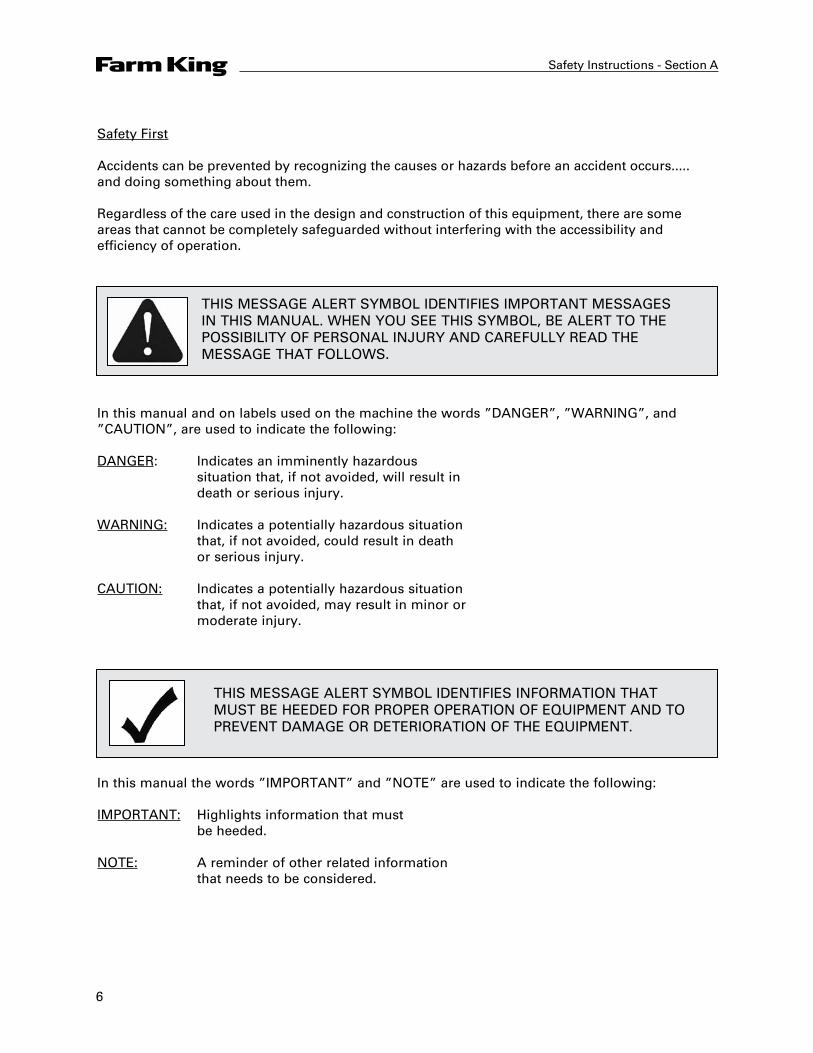
In this manual and on labels used on the machine the words ”DANGER”, ”WARNING”, and ”CAUTION”, are used to indicate the following:
DANGER: Indicates an imminently hazardous situation that, if not avoided, will result in death or serious injury.
WARNING: Indicates a potentially hazardous situation that, if not avoided, could result in death or serious injury.
CAUTION: Indicates a potentially hazardous situation that, if not avoided, may result in minor or moderate injury.
In this manual the words ”IMPORTANT” and ”NOTE” are used to indicate the following:
IMPORTANT: Highlights information that must be heeded.
NOTE: A reminder of other related information that needs to be considered.
THIS MESSAGE ALERT SYMBOL IDENTIFIES IMPORTANT MESSAGES IN THIS MANUAL. WHEN YOU SEE THIS SYMBOL, BE ALERT TO THE POSSIBILITY OF PERSONAL INJURY AND CAREFULLY READ THE MESSAGE THAT FOLLOWS.
THIS MESSAGE ALERT SYMBOL IDENTIFIES INFORMATION THAT MUST BE HEEDED FOR PROPER OPERATION OF EQUIPMENT AND TO PREVENT DAMAGE OR DETERIORATION OF THE EQUIPMENT.
7
Safety Instructions for Operation
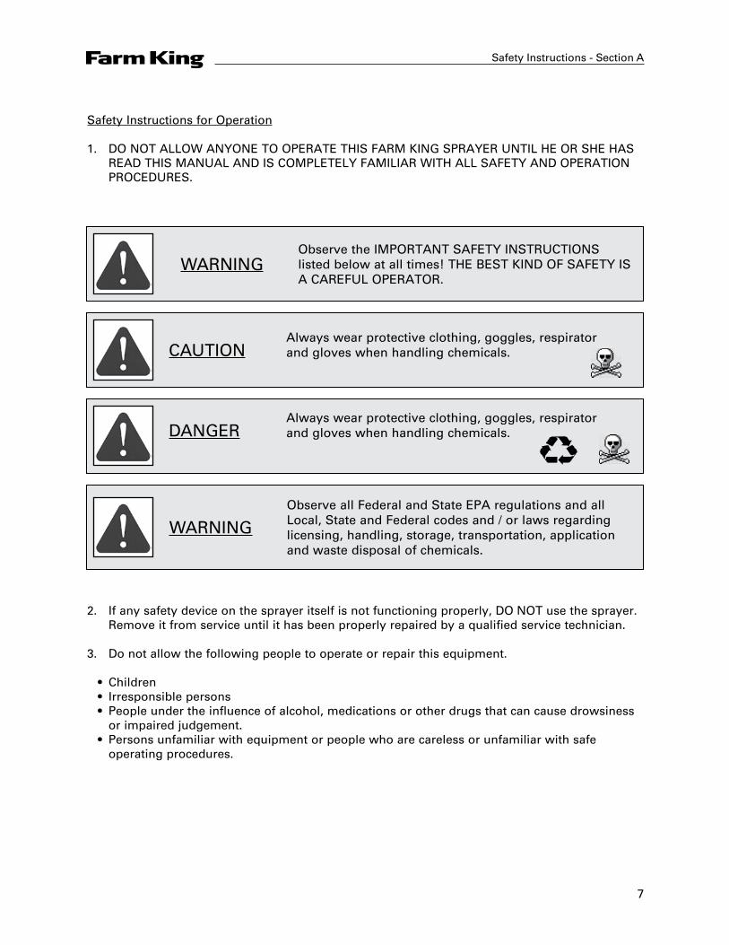
1. DO NOT ALLOW ANYONE TO OPERATE THIS FARM KING SPRAYER UNTIL HE OR SHE HAS READ THIS MANUAL AND IS COMPLETELY FAMILIAR WITH ALL SAFETY AND OPERATION PROCEDURES.
Safety Instructions - Section A
DANGERAlways wear protective clothing, goggles, respirator and gloves when handling chemicals.
2. If any safety device on the sprayer itself is not functioning properly, DO NOT use the sprayer. Remove it from service until it has been properly repaired by a qualified service technician.
3. Do not allow the following people to operate or repair this equipment.
• Children• Irresponsible persons• People under the influence of alcohol, medications or other drugs that can cause drowsiness
or impaired judgement.• Persons unfamiliar with equipment or people who are careless or unfamiliar with safe
operating procedures.
WARNINGObserve the IMPORTANT SAFETY INSTRUCTIONS listed below at all times! THE BEST KIND OF SAFETY IS A CAREFUL OPERATOR.
CAUTIONAlways wear protective clothing, goggles, respirator and gloves when handling chemicals.
WARNINGObserve all Federal and State EPA regulations and all Local, State and Federal codes and / or laws regarding licensing, handling, storage, transportation, application and waste disposal of chemicals.
8
4. People who are allergic to any of the chemicals used must never be allowed in or near the sprayer.
5. Always park the sprayer on a level surface, and lock the tractor brakes, or block the tires, before making adjustments or repairs.
6. Before operating this equipment, thoroughly inspect the unit to ensure it is in good working order.
7. Do not operate this unit if any defect or malfunction exists. Pay particular attention to safety features such as safety chains.
8. Verify that the sprayer is securely hitched to the tractor and safety chains are in place.
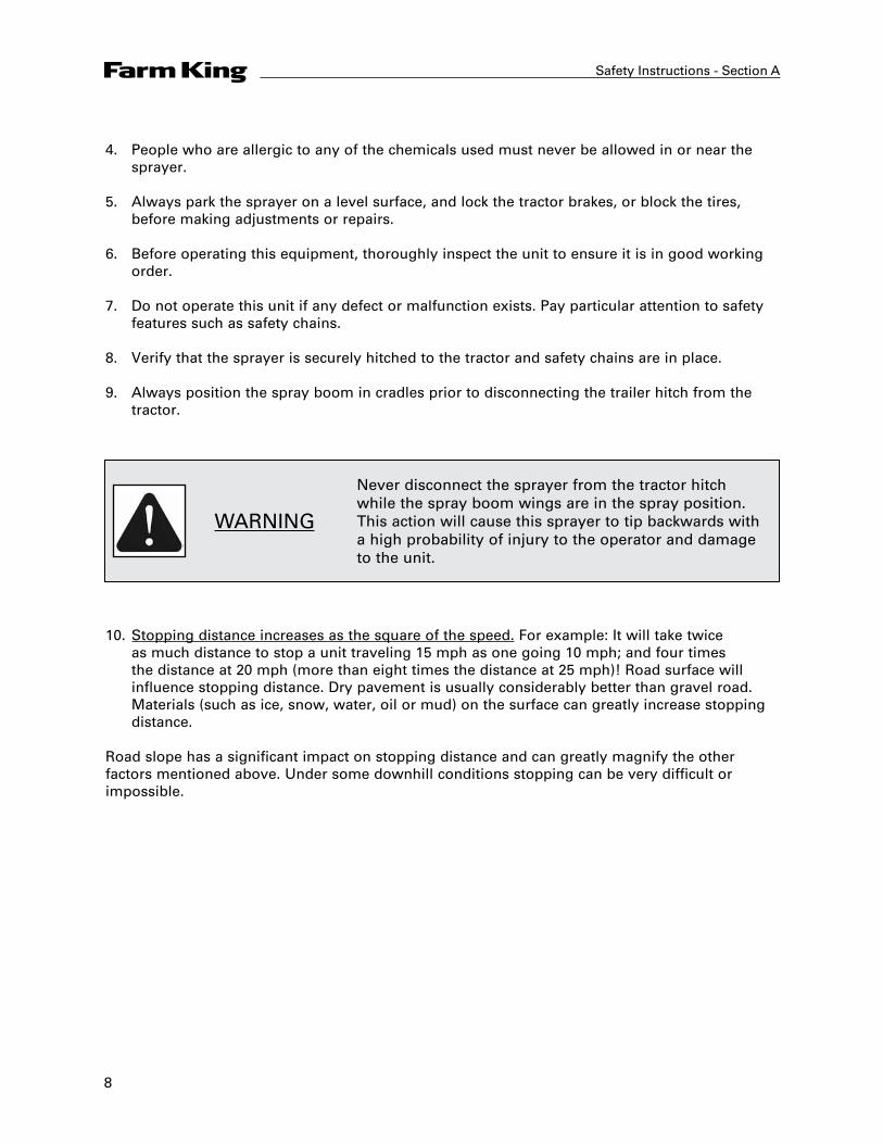
9. Always position the spray boom in cradles prior to disconnecting the trailer hitch from the tractor.
10. Stopping distance increases as the square of the speed. For example: It will take twice as much distance to stop a unit traveling 15 mph as one going 10 mph; and four times the distance at 20 mph (more than eight times the distance at 25 mph)! Road surface will influence stopping distance. Dry pavement is usually considerably better than gravel road. Materials (such as ice, snow, water, oil or mud) on the surface can greatly increase stopping distance.
Road slope has a significant impact on stopping distance and can greatly magnify the other factors mentioned above. Under some downhill conditions stopping can be very difficult or impossible.
WARNING
Never disconnect the sprayer from the tractor hitch while the spray boom wings are in the spray position. This action will cause this sprayer to tip backwards with a high probability of injury to the operator and damage to the unit.
Safety Instructions - Section A
9
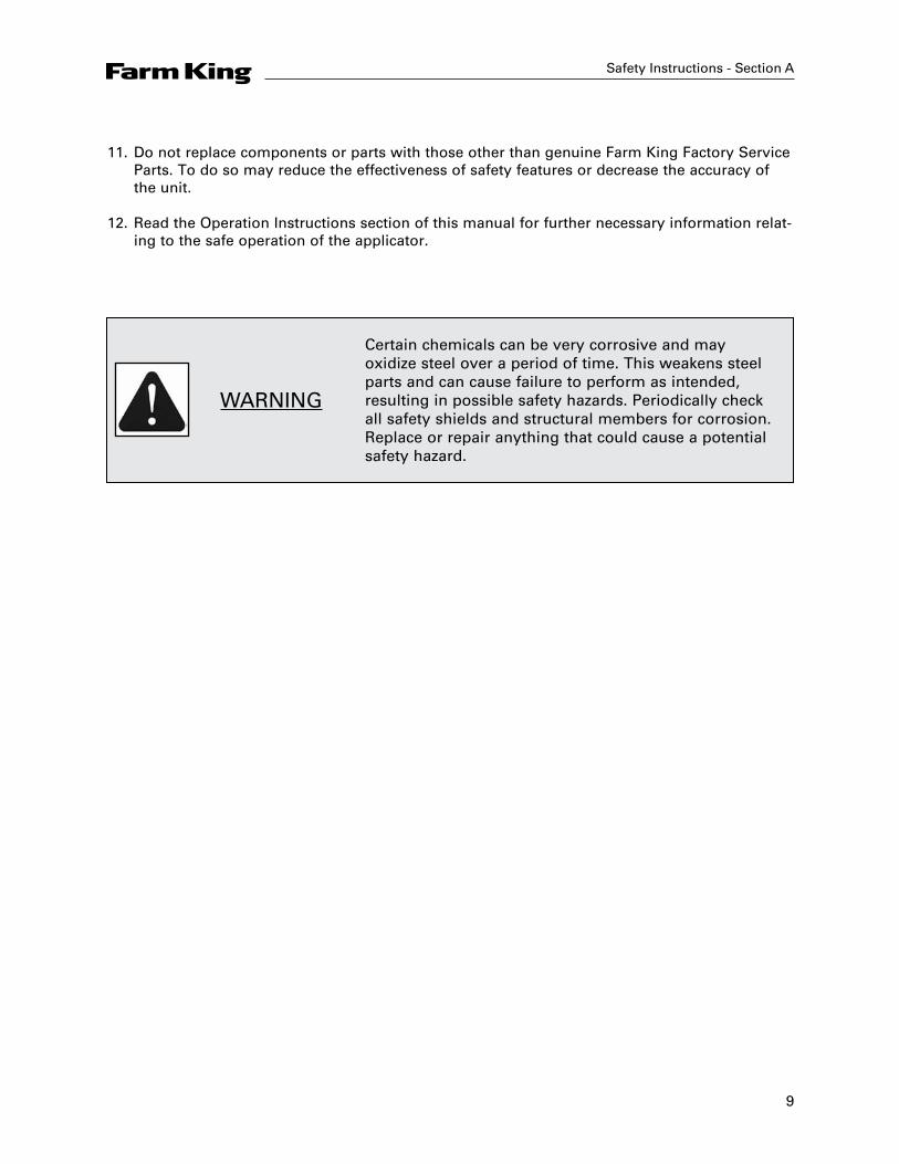
11. Do not replace components or parts with those other than genuine Farm King Factory Service Parts. To do so may reduce the effectiveness of safety features or decrease the accuracy of the unit.
12. Read the Operation Instructions section of this manual for further necessary information relat-ing to the safe operation of the applicator.
WARNING
Certain chemicals can be very corrosive and may oxidize steel over a period of time. This weakens steel parts and can cause failure to perform as intended, resulting in possible safety hazards. Periodically check all safety shields and structural members for corrosion. Replace or repair anything that could cause a potential safety hazard.
Safety Instructions - Section A
10
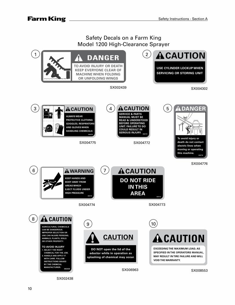
DANGERTO AVOID INJURY OR DEATHKEEP EVERYONE CLEAR OFMACHINE WHEN FOLDING
OR UNFOLDING WINGS
CAUTIONEXCEEDING THE MAXIMUM LOAD, AS
SPECIFIED IN THE OPERATORS MANUAL,
MAY RESULT IN TIRE FAILURE AND WILL
VOID THE WARRANTY.
DO NOT open the lid of theeductor while in operation as
splashing of chemical may occur.
CAUTION
DANGER
004776
To avoid injury ordeath do not contactelectric lines whenmoving or operatingthis machine.
CAUTION
004775
ALWAYS WEAR
PROTECTIVE CLOTHING
GOGGLES, RESPIRATORS
AND GLOVES WHEN
HANDLING CHEMICALS
WARNING
004774
KEEP HANDS AND
BODY AWAY FROM
AREAS WHICH
EJECT FLUIDS UNDER
HIGH PRESSURE004772
CAUTIONDO NOT RIDE
IN THISAREA
004773
CAUTIONSERVICE & PARTSMANUAL MUST BEREAD & UNDERSTOODBEFORE OPERATINGUNIT. FAILURE TO DOCOULD RESULT INSERIOUS INJURY.
004772
CAUTIONUSE CYLINDER LOCKUP WHEN
SERVICING OR STORING UNIT
CAUTIONAGRICULTURAL CHEMICALSCAN BE DANGEROUS.IMPROPER SELECTION ORUSE CAN INJURE PERSONS,ANIMALS, PLANTS, SOILSOR OTHER PROPERTY.
TO AVOID INJURY1. SELECT THE RIGHT CHEMICAL FOR THE JOB.2. HANDLE AND APPLY IT WITH CARE. FOLLOW INSTRUCTIONS ISSUED BY THE CHEMICAL MANUFACTURER.
002438
Safety Decals on a Farm King Model 1200 High-Clearance Sprayer
Safety Instructions - Section A
SX002438
8
SX004302
2
SX004772
4
7
SX004773SX004774
6
SX004775
3
SX004776
5
SX006963
9
SX008553
10
SX002439
1
11
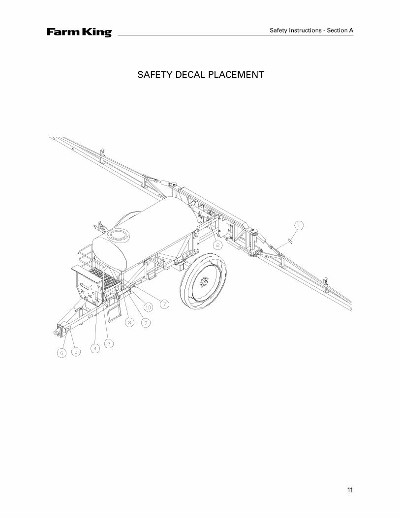
SAFETY DECAL PLACEMENT
Safety Instructions - Section A

12
NOTES:
Safety Instructions - Section A
13
Operation InstructionsSection B
14
IMPORTANTCheck machine thoroughly for screws, bolts, fittings, etc., which may have come loose during transport or operation.
CAUTION
Prior to loading with chemical, the operator needs to test the sprayer with water only to ensure the system is intact prior to putting chemical into the system. Test to verify application at the desired rate and all compo-nents work correctly.
Inspect Unit
System Overview
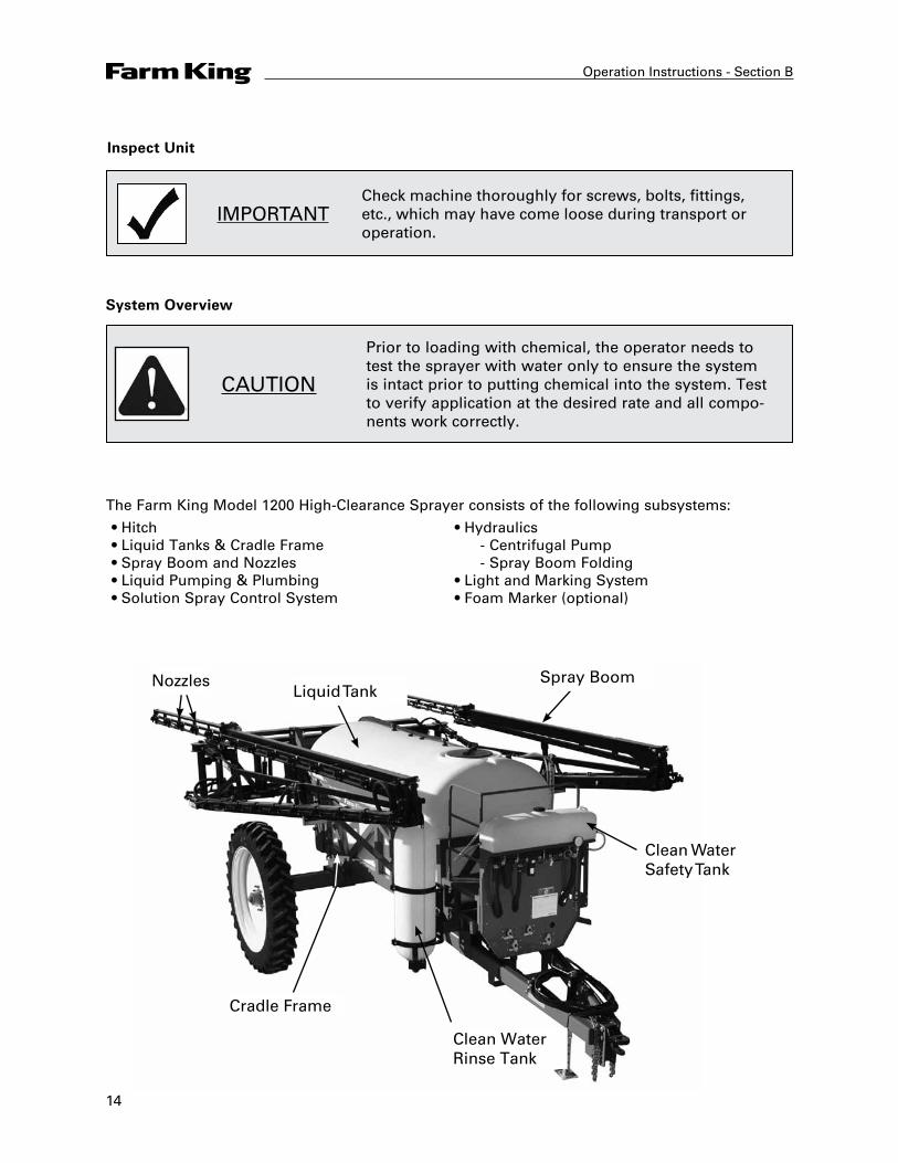
The Farm King Model 1200 High-Clearance Sprayer consists of the following subsystems:
• Hitch• Liquid Tanks & Cradle Frame• Spray Boom and Nozzles• Liquid Pumping & Plumbing• Solution Spray Control System
• Hydraulics - Centrifugal Pump - Spray Boom Folding• Light and Marking System• Foam Marker (optional)
NozzlesLiquid Tank
Spray Boom
Clean Water Safety Tank
Cradle Frame
Clean Water Rinse Tank
Operation Instructions - Section B
15
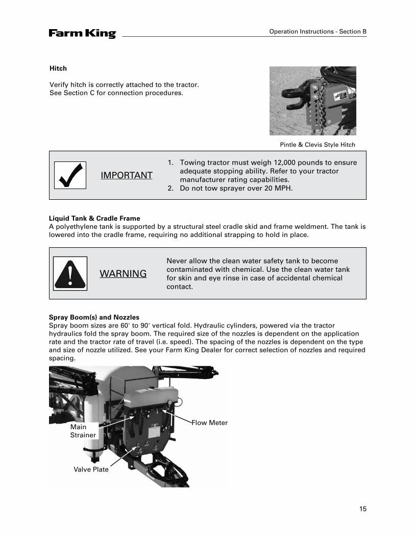
Hitch
Verify hitch is correctly attached to the tractor. See Section C for connection procedures.
Pintle & Clevis Style Hitch
IMPORTANT
1. Towing tractor must weigh 12,000 pounds to ensure adequate stopping ability. Refer to your tractor manufacturer rating capabilities.
2. Do not tow sprayer over 20 MPH.
Liquid Tank & Cradle FrameA polyethylene tank is supported by a structural steel cradle skid and frame weldment. The tank is lowered into the cradle frame, requiring no additional strapping to hold in place.
WARNINGNever allow the clean water safety tank to become contaminated with chemical. Use the clean water tank for skin and eye rinse in case of accidental chemical contact.
Spray Boom(s) and NozzlesSpray boom sizes are 60' to 90' vertical fold. Hydraulic cylinders, powered via the tractor hydraulics fold the spray boom. The required size of the nozzles is dependent on the application rate and the tractor rate of travel (i.e. speed). The spacing of the nozzles is dependent on the type and size of nozzle utilized. See your Farm King Dealer for correct selection of nozzles and required spacing.
Flow MeterMain Strainer
Valve Plate
Operation Instructions - Section B
16
Rinse BallAgitation
Spray Boom
Valve PlateClean Water
Rinse
Fresh Water
Quick Fill Connections
Solution
Pressure Gauge
Main Strainer
Valve Plate
Flow Meter
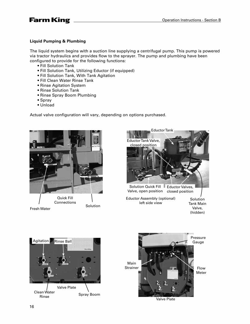
Liquid Pumping & Plumbing
The liquid system begins with a suction line supplying a centrifugal pump. This pump is powered via tractor hydraulics and provides flow to the sprayer. The pump and plumbing have been configured to provide for the following functions: • Fill Solution Tank • Fill Solution Tank, Utilizing Eductor (if equipped) • Fill Solution Tank, With Tank Agitation • Fill Clean Water Rinse Tank • Rinse Agitation System • Rinse Solution Tank • Rinse Spray Boom Plumbing • Spray • Unload
Actual valve configuration will vary, depending on options purchased.
Operation Instructions - Section B
Solution Quick Fill Valve, open position
Eductor Assembly (optional) left side view
Eductor Valves, closed position
Eductor Tank
Eductor Tank Valve, closed position
Solution Tank Main
Valve, (hidden)
17
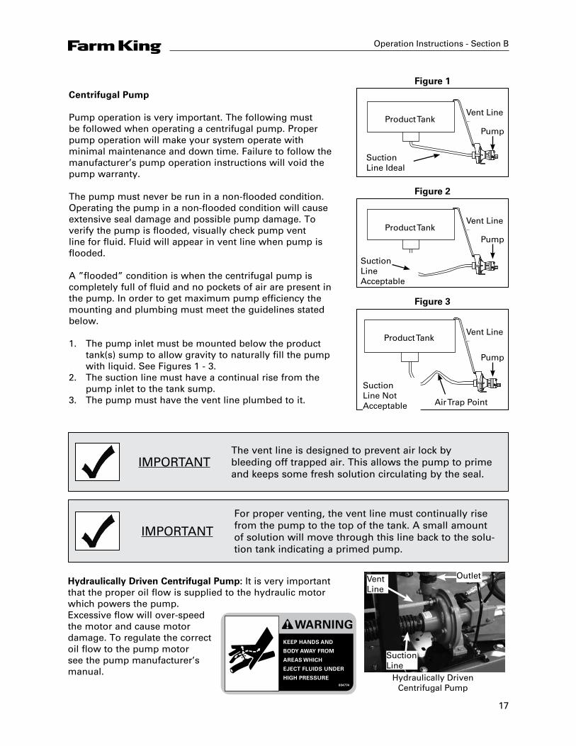
Figure 1
Vent LineProduct Tank
Pump
Suction Line Ideal
Suction Line Acceptable
Figure 2
Vent LineProduct Tank
Pump
Figure 3
Vent LineProduct Tank
Pump
Suction Line Not Acceptable Air Trap Point
IMPORTANTThe vent line is designed to prevent air lock by bleeding off trapped air. This allows the pump to prime and keeps some fresh solution circulating by the seal.
IMPORTANT
For proper venting, the vent line must continually rise from the pump to the top of the tank. A small amount of solution will move through this line back to the solu-tion tank indicating a primed pump.
Centrifugal Pump
Pump operation is very important. The following must be followed when operating a centrifugal pump. Proper pump operation will make your system operate with minimal maintenance and down time. Failure to follow the manufacturer’s pump operation instructions will void the pump warranty.
The pump must never be run in a non-flooded condition. Operating the pump in a non-flooded condition will cause extensive seal damage and possible pump damage. To verify the pump is flooded, visually check pump vent line for fluid. Fluid will appear in vent line when pump is flooded.
A ”flooded” condition is when the centrifugal pump is completely full of fluid and no pockets of air are present in the pump. In order to get maximum pump efficiency the mounting and plumbing must meet the guidelines stated below.
1. The pump inlet must be mounted below the product tank(s) sump to allow gravity to naturally fill the pump with liquid. See Figures 1 - 3.
2. The suction line must have a continual rise from the pump inlet to the tank sump.
3. The pump must have the vent line plumbed to it.
Hydraulically Driven Centrifugal Pump
Vent Line
Outlet
Suction Line
Hydraulically Driven Centrifugal Pump: It is very important that the proper oil flow is supplied to the hydraulic motor which powers the pump. Excessive flow will over-speed the motor and cause motor damage. To regulate the correct oil flow to the pump motor see the pump manufacturer’s manual.
Operation Instructions - Section B
WARNING
004774
KEEP HANDS AND
BODY AWAY FROM
AREAS WHICH
EJECT FLUIDS UNDER
HIGH PRESSURE
18
IMPORTANT
Turn off a hydraulically driven centrifugal pump using the ”float” position of the tractor’s hydraulic valve. This allows the motor to stop slowly helping to protect the motor and motor seals.
IMPORTANT
There are two basic rules to follow when operating a hydraulically driven centrifugal pump:1. Never run the pump in a ”non-flooded” condition.2. Always have the correct oil flow to the pump motor.Always read and follow the pump manufacturer’s oper-ational instructions.
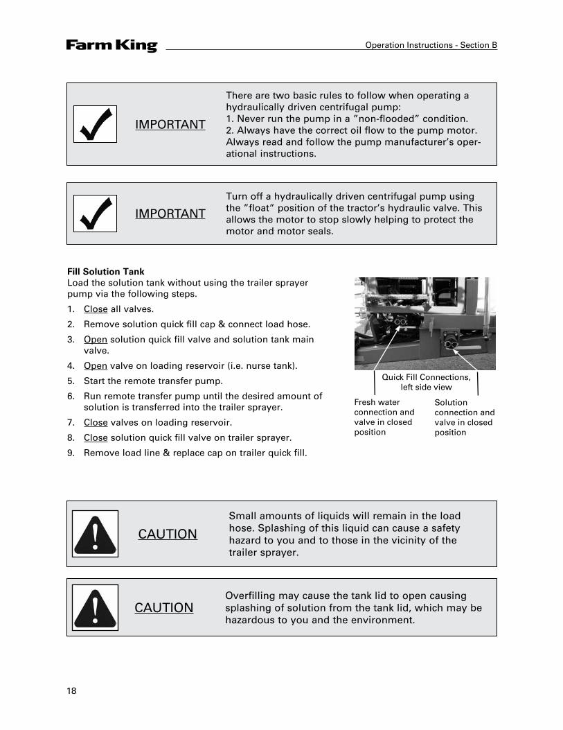
Fill Solution TankLoad the solution tank without using the trailer sprayer pump via the following steps.
1. Close all valves.
2. Remove solution quick fill cap & connect load hose.
3. Open solution quick fill valve and solution tank main valve.
4. Open valve on loading reservoir (i.e. nurse tank).
5. Start the remote transfer pump.
6. Run remote transfer pump until the desired amount of solution is transferred into the trailer sprayer.
7. Close valves on loading reservoir.
8. Close solution quick fill valve on trailer sprayer.
9. Remove load line & replace cap on trailer quick fill.
CAUTIONSmall amounts of liquids will remain in the load hose. Splashing of this liquid can cause a safety hazard to you and to those in the vicinity of the trailer sprayer.
CAUTIONOverfilling may cause the tank lid to open causing splashing of solution from the tank lid, which may be hazardous to you and the environment.
Quick Fill Connections, left side view
Fresh water connection and valve in closed position
Solution connection and valve in closed position
Operation Instructions - Section B
19
DO NOT open the lid of theeductor while in operation as
splashing of chemical may occur.
CAUTION
CAUTIONAGRICULTURAL CHEMICALSCAN BE DANGEROUS.IMPROPER SELECTION ORUSE CAN INJURE PERSONS,ANIMALS, PLANTS, SOILSOR OTHER PROPERTY.
TO AVOID INJURY1. SELECT THE RIGHT CHEMICAL FOR THE JOB.2. HANDLE AND APPLY IT WITH CARE. FOLLOW INSTRUCTIONS ISSUED BY THE CHEMICAL MANUFACTURER.
002438
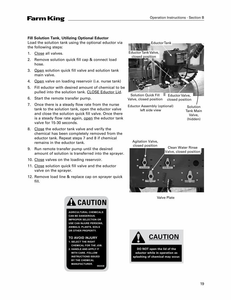
Fill Solution Tank, Utilizing Optional Eductor Load the solution tank using the optional eductor via the following steps:
1. Close all valves.
2. Remove solution quick fill cap & connect load hose.
3. Open solution quick fill valve and solution tank main valve.
4. Open valve on loading reservoir (i.e. nurse tank)
5. Fill eductor with desired amount of chemical to be pulled into the solution tank. CLOSE Eductor Lid.
6. Start the remote transfer pump.
7. Once there is a steady flow rate from the nurse tank to the solution tank, open the eductor valve and close the solution quick fill valve. Once there is a steady flow rate again, open the eductor tank valve for 15-30 seconds.
8. Close the eductor tank valve and verify the chemical has been completely removed from the eductor tank. Repeat steps 7 and 8 if chemical remains in the eductor tank.
9. Run remote transfer pump until the desired amount of solution is transferred into the sprayer.
10. Close valves on the loading reservoir.
11. Close solution quick fill valve and the eductor valve on the sprayer.
12. Remove load line & replace cap on sprayer quick fill.
Operation Instructions - Section B
Valve Plate
Agitation Valve, closed position Clean Water Rinse
Valve, closed position
Solution Quick Fill Valve, closed position
Eductor Assembly (optional) left side view
Eductor Valve, closed position
Eductor Tank
Eductor Tank Valve, closed position
Solution Tank Main
Valve, (hidden)
20
IMPORTANT
Turn off a hydraulically driven centrifugal pump using the ”float” position of the tractor’s hydraulic valve. This allows the motor to stop slowly helping to protect the motor and motor seals.
IMPORTANTOnly you, the operator, can determine the length of time required to completely rinse all chemical residue from the sprayer tanks and plumbing systems.
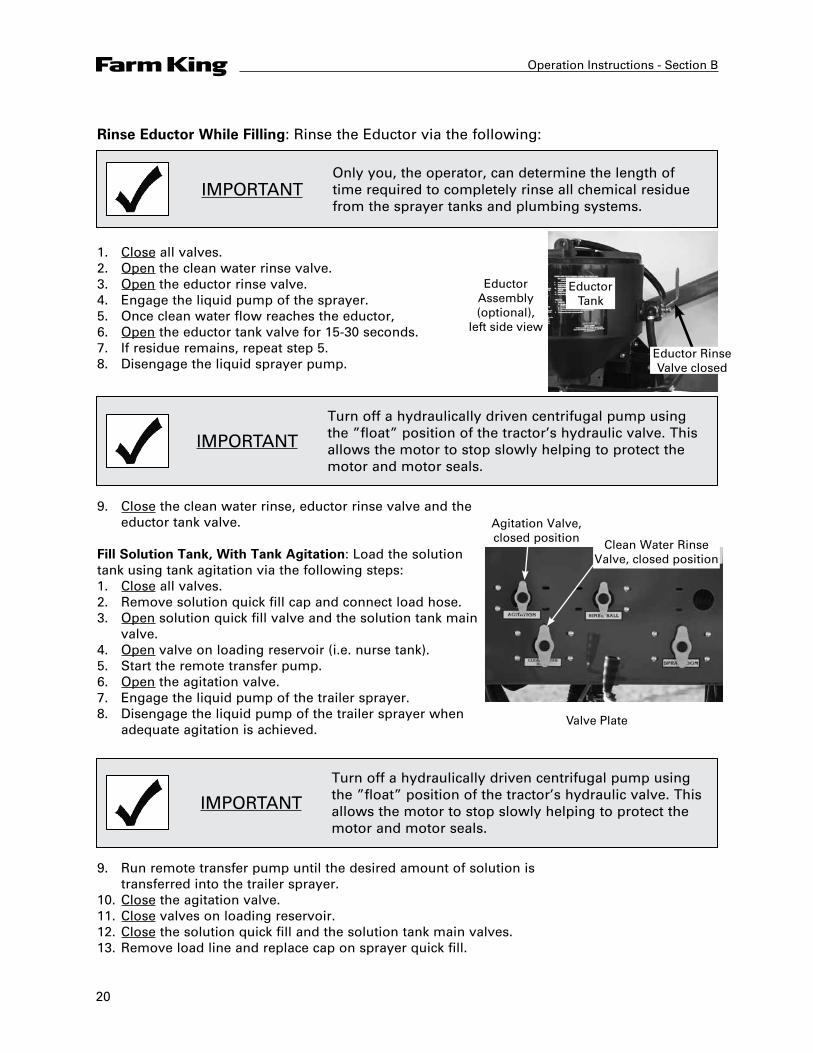
Rinse Eductor While Filling: Rinse the Eductor via the following:
1. Close all valves.2. Open the clean water rinse valve.3. Open the eductor rinse valve.4. Engage the liquid pump of the sprayer.5. Once clean water flow reaches the eductor,6. Open the eductor tank valve for 15-30 seconds.7. If residue remains, repeat step 5.8. Disengage the liquid sprayer pump.
IMPORTANT
Turn off a hydraulically driven centrifugal pump using the ”float” position of the tractor’s hydraulic valve. This allows the motor to stop slowly helping to protect the motor and motor seals.
9. Close the clean water rinse, eductor rinse valve and the eductor tank valve.
Fill Solution Tank, With Tank Agitation: Load the solution tank using tank agitation via the following steps:1. Close all valves.2. Remove solution quick fill cap and connect load hose.3. Open solution quick fill valve and the solution tank main
valve.4. Open valve on loading reservoir (i.e. nurse tank).5. Start the remote transfer pump.6. Open the agitation valve.7. Engage the liquid pump of the trailer sprayer. 8. Disengage the liquid pump of the trailer sprayer when
adequate agitation is achieved.
9. Run remote transfer pump until the desired amount of solution is transferred into the trailer sprayer.
10. Close the agitation valve.11. Close valves on loading reservoir.12. Close the solution quick fill and the solution tank main valves.13. Remove load line and replace cap on sprayer quick fill.
Eductor Rinse Valve closed
Eductor Tank
Eductor Assembly (optional),
left side view
Operation Instructions - Section B
Valve Plate
Agitation Valve, closed position Clean Water Rinse
Valve, closed position
21
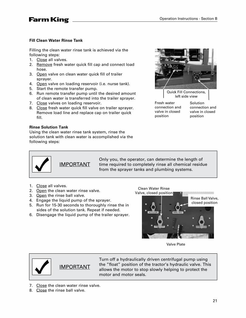
Fill Clean Water Rinse Tank
Filling the clean water rinse tank is achieved via the following steps:1. Close all valves.2. Remove fresh water quick fill cap and connect load
hose.3. Open valve on clean water quick fill of trailer
sprayer.4. Open valve on loading reservoir (i.e. nurse tank).5. Start the remote transfer pump.6. Run remote transfer pump until the desired amount
of clean water is transferred into the trailer sprayer.7. Close valves on loading reservoir.8. Close fresh water quick fill valve on trailer sprayer.
Remove load line and replace cap on trailer quick fill.
Rinse Solution TankUsing the clean water rinse tank system, rinse the solution tank with clean water is accomplished via the following steps:
IMPORTANT
Turn off a hydraulically driven centrifugal pump using the ”float” position of the tractor’s hydraulic valve. This allows the motor to stop slowly helping to protect the motor and motor seals.
IMPORTANTOnly you, the operator, can determine the length of time required to completely rinse all chemical residue from the sprayer tanks and plumbing systems.
1. Close all valves.2. Open the clean water rinse valve.3. Open the rinse ball valve.4. Engage the liquid pump of the sprayer.5. Run for 15-30 seconds to thoroughly rinse the in
sides of the solution tank. Repeat if needed.6. Disengage the liquid pump of the trailer sprayer.
7. Close the clean water rinse valve.8. Close the rinse ball valve.
Quick Fill Connections, left side view
Fresh water connection and valve in closed position
Solution connection and valve in closed position
Operation Instructions - Section B
Valve Plate
Rinse Ball Valve, closed position
Clean Water Rinse Valve, closed position
22
Spray Boom Section Valves
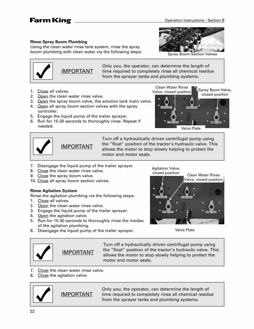
Rinse Spray Boom PlumbingUsing the clean water rinse tank system, rinse the spray boom plumbing with clean water via the following steps:
IMPORTANTOnly you, the operator, can determine the length of time required to completely rinse all chemical residue from the sprayer tanks and plumbing systems.
1. Close all valves.2. Open the clean water rinse valve.3. Open the spray boom valve, the solution tank main valve.4. Open all spray boom section valves with the spray
controller.5. Engage the liquid pump of the trailer sprayer.6. Run for 15-30 seconds to thoroughly rinse. Repeat if
needed.
IMPORTANT
Turn off a hydraulically driven centrifugal pump using the ”float” position of the tractor’s hydraulic valve. This allows the motor to stop slowly helping to protect the motor and motor seals.
7. Disengage the liquid pump of the trailer sprayer.8. Close the clean water rinse valve.9. Close the spray boom valve.10. Close all spray boom section valves.
Rinse Agitation SystemRinse the agitation plumbing via the following steps:1. Close all valves.2. Open the clean water rinse valve.3. Engage the liquid pump of the trailer sprayer.4. Open the agitation valve.5. Run for 15-30 seconds to thoroughly rinse the insides
of the agitation plumbing.6. Disengage the liquid pump of the trailer sprayer.
IMPORTANT
Turn off a hydraulically driven centrifugal pump using the ”float” position of the tractor’s hydraulic valve. This allows the motor to stop slowly helping to protect the motor and motor seals.
7. Close the clean water rinse valve.8. Close the agitation valve.
IMPORTANTOnly you, the operator, can determine the length of time required to completely rinse all chemical residue from the sprayer tanks and plumbing systems.
Operation Instructions - Section B
Valve Plate
Spray Boom Valve, closed position
Clean Water Rinse Valve, closed position
Valve Plate
Agitation Valve, closed position Clean Water Rinse
Valve, closed position
23
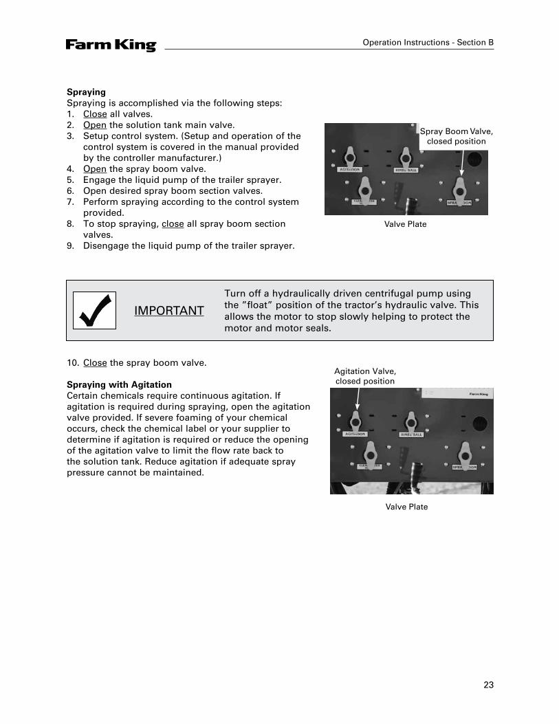
SprayingSpraying is accomplished via the following steps:1. Close all valves.2. Open the solution tank main valve.3. Setup control system. (Setup and operation of the
control system is covered in the manual provided by the controller manufacturer.)
4. Open the spray boom valve.5. Engage the liquid pump of the trailer sprayer.6. Open desired spray boom section valves.7. Perform spraying according to the control system
provided.8. To stop spraying, close all spray boom section
valves.9. Disengage the liquid pump of the trailer sprayer.
IMPORTANT
Turn off a hydraulically driven centrifugal pump using the ”float” position of the tractor’s hydraulic valve. This allows the motor to stop slowly helping to protect the motor and motor seals.
10. Close the spray boom valve.
Spraying with AgitationCertain chemicals require continuous agitation. If agitation is required during spraying, open the agitation valve provided. If severe foaming of your chemical occurs, check the chemical label or your supplier to determine if agitation is required or reduce the opening of the agitation valve to limit the flow rate back to the solution tank. Reduce agitation if adequate spray pressure cannot be maintained.
Operation Instructions - Section B
Valve Plate
Spray Boom Valve, closed position
Valve Plate
Agitation Valve, closed position
24
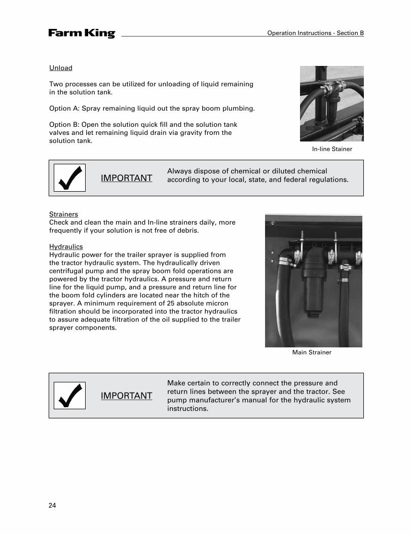
Main Strainer
IMPORTANTAlways dispose of chemical or diluted chemical according to your local, state, and federal regulations.
StrainersCheck and clean the main and In-line strainers daily, more frequently if your solution is not free of debris.
HydraulicsHydraulic power for the trailer sprayer is supplied from the tractor hydraulic system. The hydraulically driven centrifugal pump and the spray boom fold operations are powered by the tractor hydraulics. A pressure and return line for the liquid pump, and a pressure and return line for the boom fold cylinders are located near the hitch of the sprayer. A minimum requirement of 25 absolute micron filtration should be incorporated into the tractor hydraulics to assure adequate filtration of the oil supplied to the trailer sprayer components.
Unload
Two processes can be utilized for unloading of liquid remaining in the solution tank.
Option A: Spray remaining liquid out the spray boom plumbing.
Option B: Open the solution quick fill and the solution tank valves and let remaining liquid drain via gravity from the solution tank.
IMPORTANT
Make certain to correctly connect the pressure and return lines between the sprayer and the tractor. See pump manufacturer’s manual for the hydraulic system instructions.
In-line Stainer
Operation Instructions - Section B
25
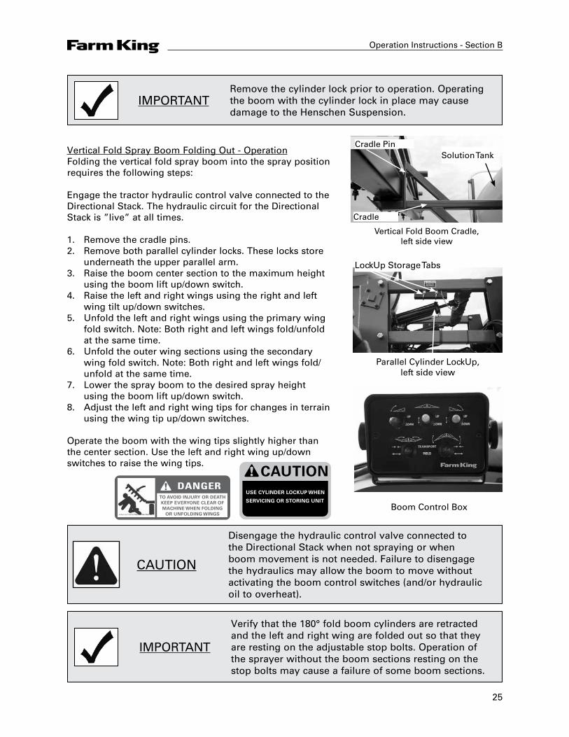
IMPORTANTRemove the cylinder lock prior to operation. Operating the boom with the cylinder lock in place may cause damage to the Henschen Suspension.
Vertical Fold Spray Boom Folding Out - OperationFolding the vertical fold spray boom into the spray position requires the following steps:
Engage the tractor hydraulic control valve connected to the Directional Stack. The hydraulic circuit for the Directional Stack is ”live” at all times.
1. Remove the cradle pins.2. Remove both parallel cylinder locks. These locks store
underneath the upper parallel arm.3. Raise the boom center section to the maximum height
using the boom lift up/down switch.4. Raise the left and right wings using the right and left
wing tilt up/down switches.5. Unfold the left and right wings using the primary wing
fold switch. Note: Both right and left wings fold/unfold at the same time.
6. Unfold the outer wing sections using the secondary wing fold switch. Note: Both right and left wings fold/unfold at the same time.
7. Lower the spray boom to the desired spray height using the boom lift up/down switch.
8. Adjust the left and right wing tips for changes in terrain using the wing tip up/down switches.
Operate the boom with the wing tips slightly higher than the center section. Use the left and right wing up/down switches to raise the wing tips.
IMPORTANT
Verify that the 180° fold boom cylinders are retracted and the left and right wing are folded out so that they are resting on the adjustable stop bolts. Operation of the sprayer without the boom sections resting on the stop bolts may cause a failure of some boom sections.
CAUTION
Disengage the hydraulic control valve connected to the Directional Stack when not spraying or when boom movement is not needed. Failure to disengage the hydraulics may allow the boom to move without activating the boom control switches (and/or hydraulic oil to overheat).
Solution Tank
Cradle
Cradle Pin
Vertical Fold Boom Cradle, left side view
LockUp Storage Tabs
Parallel Cylinder LockUp, left side view
Boom Control Box
Operation Instructions - Section B
CAUTIONUSE CYLINDER LOCKUP WHEN
SERVICING OR STORING UNIT
DANGERTO AVOID INJURY OR DEATHKEEP EVERYONE CLEAR OFMACHINE WHEN FOLDING
OR UNFOLDING WINGS
26
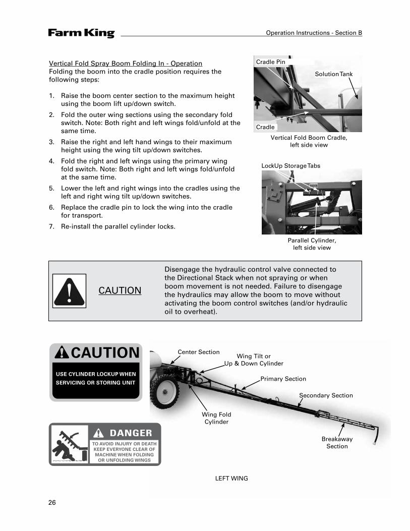
Center SectionWing Tilt or
Up & Down Cylinder
Primary Section
Secondary Section
Wing Fold Cylinder
Breakaway Section
LEFT WING
Vertical Fold Boom Cradle,left side view
Parallel Cylinder,left side view
Vertical Fold Spray Boom Folding In - OperationFolding the boom into the cradle position requires the following steps:
1. Raise the boom center section to the maximum height using the boom lift up/down switch.
2. Fold the outer wing sections using the secondary fold switch. Note: Both right and left wings fold/unfold at the same time.
3. Raise the right and left hand wings to their maximum height using the wing tilt up/down switches.
4. Fold the right and left wings using the primary wing fold switch. Note: Both right and left wings fold/unfold at the same time.
5. Lower the left and right wings into the cradles using the left and right wing tilt up/down switches.
6. Replace the cradle pin to lock the wing into the cradle for transport.
7. Re-install the parallel cylinder locks.
CAUTION
Disengage the hydraulic control valve connected to the Directional Stack when not spraying or when boom movement is not needed. Failure to disengage the hydraulics may allow the boom to move without activating the boom control switches (and/or hydraulic oil to overheat).
Operation Instructions - Section B
CAUTIONUSE CYLINDER LOCKUP WHEN
SERVICING OR STORING UNIT
DANGERTO AVOID INJURY OR DEATHKEEP EVERYONE CLEAR OFMACHINE WHEN FOLDING
OR UNFOLDING WINGS
Cradle Pin
Cradle
Solution Tank
LockUp Storage Tabs
27
Lights and Rear Facing Reflective and Florescent Decals
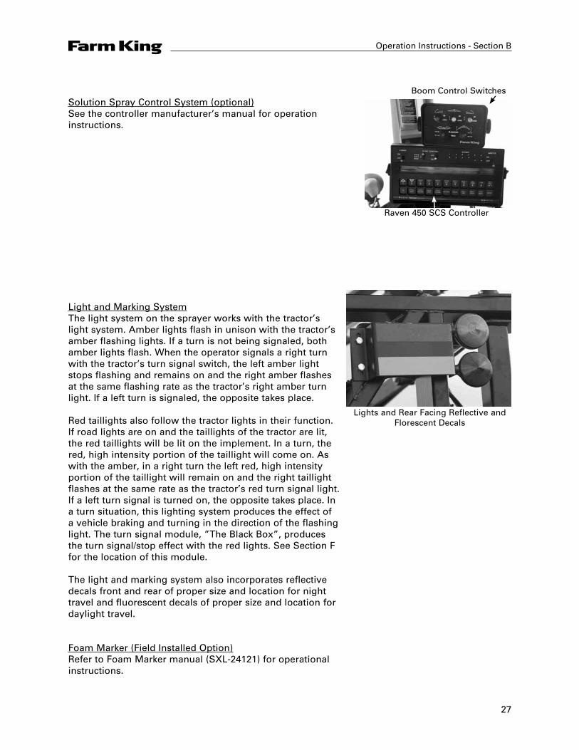
Solution Spray Control System (optional)See the controller manufacturer’s manual for operation instructions.
Light and Marking SystemThe light system on the sprayer works with the tractor’s light system. Amber lights flash in unison with the tractor’s amber flashing lights. If a turn is not being signaled, both amber lights flash. When the operator signals a right turn with the tractor’s turn signal switch, the left amber light stops flashing and remains on and the right amber flashes at the same flashing rate as the tractor’s right amber turn light. If a left turn is signaled, the opposite takes place.
Red taillights also follow the tractor lights in their function. If road lights are on and the taillights of the tractor are lit, the red taillights will be lit on the implement. In a turn, the red, high intensity portion of the taillight will come on. As with the amber, in a right turn the left red, high intensity portion of the taillight will remain on and the right taillight flashes at the same rate as the tractor’s red turn signal light. If a left turn signal is turned on, the opposite takes place. In a turn situation, this lighting system produces the effect of a vehicle braking and turning in the direction of the flashing light. The turn signal module, ”The Black Box”, produces the turn signal/stop effect with the red lights. See Section F for the location of this module.
The light and marking system also incorporates reflective decals front and rear of proper size and location for night travel and fluorescent decals of proper size and location for daylight travel.
Foam Marker (Field Installed Option)Refer to Foam Marker manual (SXL-24121) for operational instructions.
Operation Instructions - Section B
Raven 450 SCS Controller
Boom Control Switches

28
NOTES:
Operation Instructions - Section B

29
Connection & StartupSection C
30
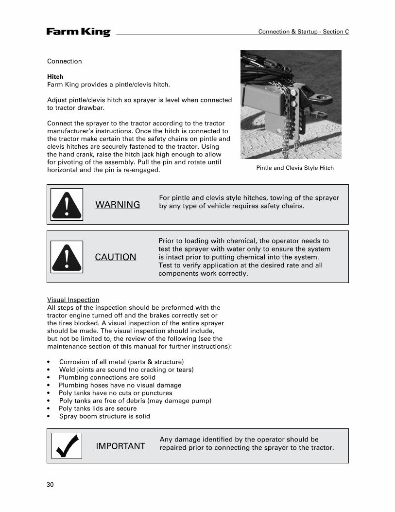
Pintle and Clevis Style Hitch
IMPORTANTAny damage identified by the operator should be repaired prior to connecting the sprayer to the tractor.
Connection
HitchFarm King provides a pintle/clevis hitch.
Adjust pintle/clevis hitch so sprayer is level when connected to tractor drawbar.
Connect the sprayer to the tractor according to the tractor manufacturer’s instructions. Once the hitch is connected to the tractor make certain that the safety chains on pintle and clevis hitches are securely fastened to the tractor. Using the hand crank, raise the hitch jack high enough to allow for pivoting of the assembly. Pull the pin and rotate until horizontal and the pin is re-engaged.
Visual InspectionAll steps of the inspection should be preformed with the tractor engine turned off and the brakes correctly set or the tires blocked. A visual inspection of the entire sprayer should be made. The visual inspection should include, but not be limited to, the review of the following (see the maintenance section of this manual for further instructions):
• Corrosion of all metal (parts & structure)• Weld joints are sound (no cracking or tears)• Plumbing connections are solid• Plumbing hoses have no visual damage• Poly tanks have no cuts or punctures• Poly tanks are free of debris (may damage pump)• Poly tanks lids are secure• Spray boom structure is solid
WARNINGFor pintle and clevis style hitches, towing of the sprayer by any type of vehicle requires safety chains.
CAUTION
Prior to loading with chemical, the operator needs to test the sprayer with water only to ensure the system is intact prior to putting chemical into the system. Test to verify application at the desired rate and all components work correctly.
Connection & Startup - Section C
31
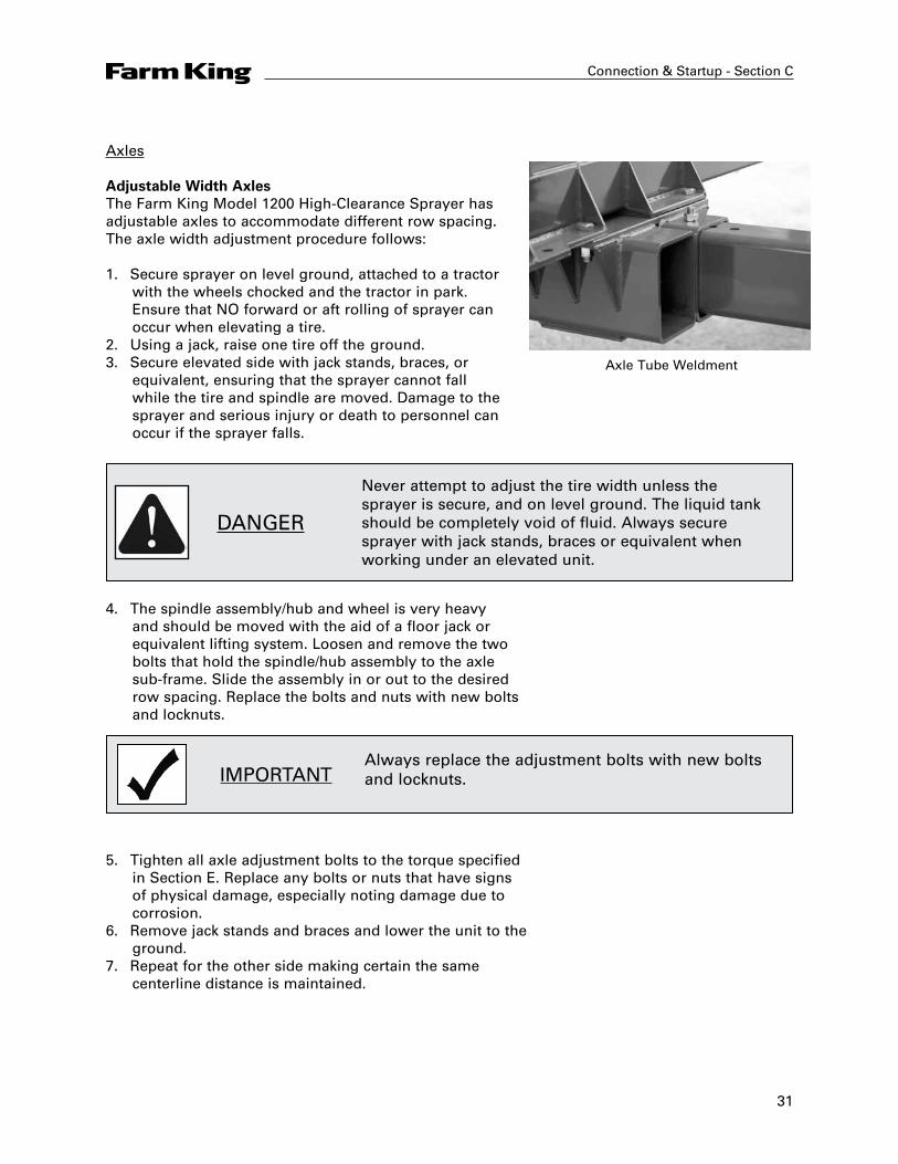
Axle Tube Weldment
IMPORTANTAlways replace the adjustment bolts with new bolts and locknuts.
DANGER
Never attempt to adjust the tire width unless the sprayer is secure, and on level ground. The liquid tank should be completely void of fluid. Always secure sprayer with jack stands, braces or equivalent when working under an elevated unit.
Axles
Adjustable Width AxlesThe Farm King Model 1200 High-Clearance Sprayer has adjustable axles to accommodate different row spacing. The axle width adjustment procedure follows:
1. Secure sprayer on level ground, attached to a tractor with the wheels chocked and the tractor in park. Ensure that NO forward or aft rolling of sprayer can occur when elevating a tire.
2. Using a jack, raise one tire off the ground.3. Secure elevated side with jack stands, braces, or
equivalent, ensuring that the sprayer cannot fall while the tire and spindle are moved. Damage to the sprayer and serious injury or death to personnel can occur if the sprayer falls.
4. The spindle assembly/hub and wheel is very heavy and should be moved with the aid of a floor jack or equivalent lifting system. Loosen and remove the two bolts that hold the spindle/hub assembly to the axle sub-frame. Slide the assembly in or out to the desired row spacing. Replace the bolts and nuts with new bolts and locknuts.
5. Tighten all axle adjustment bolts to the torque specified in Section E. Replace any bolts or nuts that have signs of physical damage, especially noting damage due to corrosion.
6. Remove jack stands and braces and lower the unit to the ground.
7. Repeat for the other side making certain the same centerline distance is maintained.
Connection & Startup - Section C
32
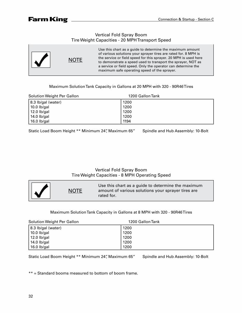
NOTEUse this chart as a guide to determine the maximum amount of various solutions your sprayer tires are rated for.
NOTE
Use this chart as a guide to determine the maximum amount of various solutions your sprayer tires are rated for. 8 MPH is the service or field speed for this sprayer. 20 MPH is used here to demonstrate a speed used to transport the sprayer, NOT as a service or field speed. Only the operator can determine the maximum safe operating speed of the sprayer.
Connection & Startup - Section C
Maximum Solution Tank Capacity in Gallons at 20 MPH with 320 - 90R46 Tires
Solution Weight Per Gallon 1200 Gallon Tank
8.3 lb/gal (water)10.0 lb/gal12.0 lb/gal14.0 lb/gal16.0 lb/gal
12001200120012001194
Static Load Boom Height ** Minimum 24”, Maximum 65” Spindle and Hub Assembly: 10-Bolt
Maximum Solution Tank Capacity in Gallons at 8 MPH with 320 - 90R46 Tires
Solution Weight Per Gallon 1200 Gallon Tank
8.3 lb/gal (water)10.0 lb/gal12.0 lb/gal14.0 lb/gal16.0 lb/gal
12001200120012001200
Static Load Boom Height ** Minimum 24”, Maximum 65” Spindle and Hub Assembly: 10-Bolt
** = Standard booms measured to bottom of boom frame.
Vertical Fold Spray BoomTire Weight Capacities - 8 MPH Operating Speed
Vertical Fold Spray BoomTire Weight Capacities - 20 MPH Transport Speed
33
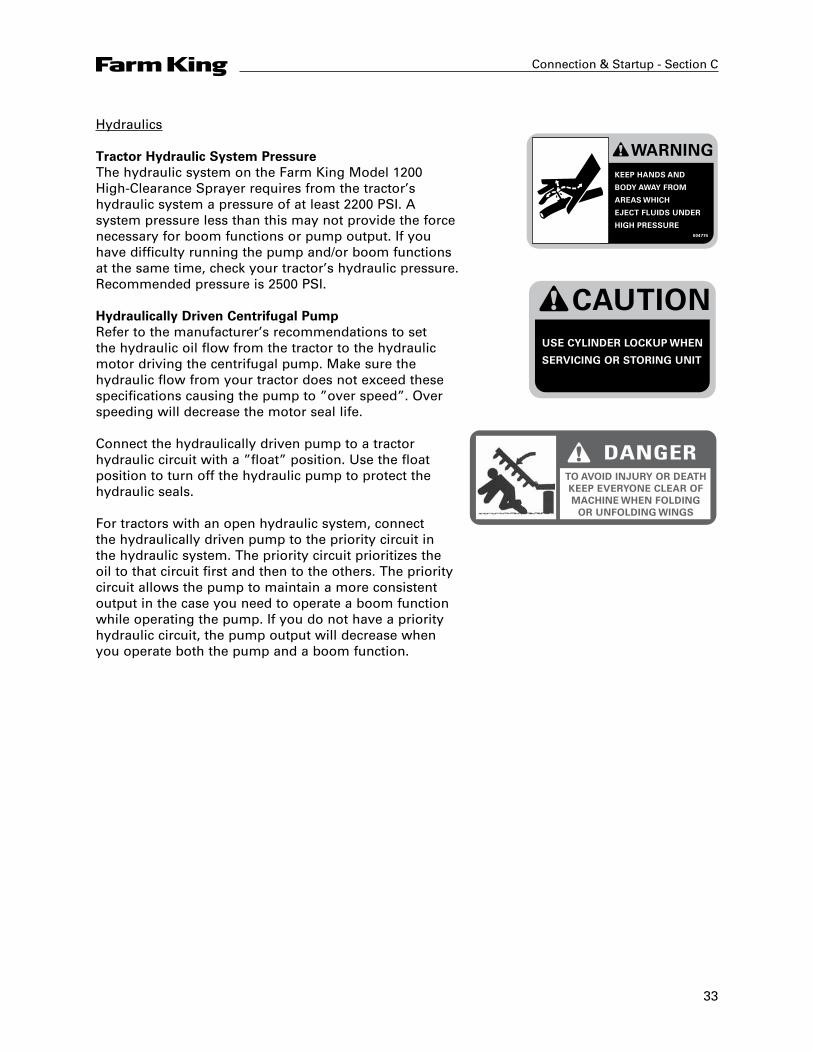
CAUTIONUSE CYLINDER LOCKUP WHEN
SERVICING OR STORING UNIT
WARNING
004774
KEEP HANDS AND
BODY AWAY FROM
AREAS WHICH
EJECT FLUIDS UNDER
HIGH PRESSURE
Hydraulics
Tractor Hydraulic System PressureThe hydraulic system on the Farm King Model 1200 High-Clearance Sprayer requires from the tractor’s hydraulic system a pressure of at least 2200 PSI. A system pressure less than this may not provide the force necessary for boom functions or pump output. If you have difficulty running the pump and/or boom functions at the same time, check your tractor’s hydraulic pressure. Recommended pressure is 2500 PSI.
Hydraulically Driven Centrifugal PumpRefer to the manufacturer’s recommendations to set the hydraulic oil flow from the tractor to the hydraulic motor driving the centrifugal pump. Make sure the hydraulic flow from your tractor does not exceed these specifications causing the pump to ”over speed”. Over speeding will decrease the motor seal life.
Connect the hydraulically driven pump to a tractor hydraulic circuit with a ”float” position. Use the float position to turn off the hydraulic pump to protect the hydraulic seals.
For tractors with an open hydraulic system, connect the hydraulically driven pump to the priority circuit in the hydraulic system. The priority circuit prioritizes the oil to that circuit first and then to the others. The priority circuit allows the pump to maintain a more consistent output in the case you need to operate a boom function while operating the pump. If you do not have a priority hydraulic circuit, the pump output will decrease when you operate both the pump and a boom function.
Connection & Startup - Section C
DANGERTO AVOID INJURY OR DEATHKEEP EVERYONE CLEAR OFMACHINE WHEN FOLDING
OR UNFOLDING WINGS
34
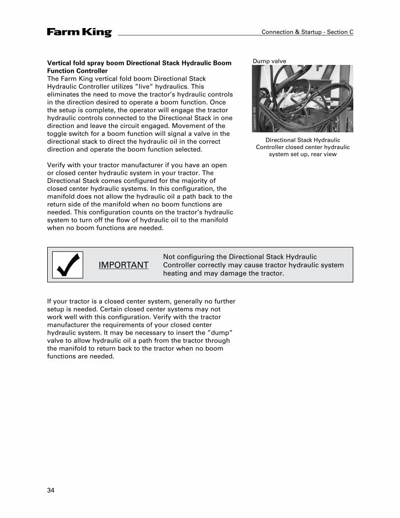
Vertical fold spray boom Directional Stack Hydraulic Boom Function Controller The Farm King vertical fold boom Directional Stack Hydraulic Controller utilizes ”live” hydraulics. This eliminates the need to move the tractor’s hydraulic controls in the direction desired to operate a boom function. Once the setup is complete, the operator will engage the tractor hydraulic controls connected to the Directional Stack in one direction and leave the circuit engaged. Movement of the toggle switch for a boom function will signal a valve in the directional stack to direct the hydraulic oil in the correct direction and operate the boom function selected.
Verify with your tractor manufacturer if you have an open or closed center hydraulic system in your tractor. The Directional Stack comes configured for the majority of closed center hydraulic systems. In this configuration, the manifold does not allow the hydraulic oil a path back to the return side of the manifold when no boom functions are needed. This configuration counts on the tractor’s hydraulic system to turn off the flow of hydraulic oil to the manifold when no boom functions are needed.
IMPORTANTNot configuring the Directional Stack Hydraulic Controller correctly may cause tractor hydraulic system heating and may damage the tractor.
If your tractor is a closed center system, generally no further setup is needed. Certain closed center systems may not work well with this configuration. Verify with the tractor manufacturer the requirements of your closed center hydraulic system. It may be necessary to insert the ”dump” valve to allow hydraulic oil a path from the tractor through the manifold to return back to the tractor when no boom functions are needed.
Dump valve
Directional Stack Hydraulic Controller closed center hydraulic
system set up, rear view
Connection & Startup - Section C
35
If your system is an open center system, or certain closed center systems, configure the Directional Stack to account for this by following these instructions:
IMPORTANTNot configuring the Directional Stack Hydraulic Controller correctly may cause tractor hydraulic system heating and may damage the tractor.
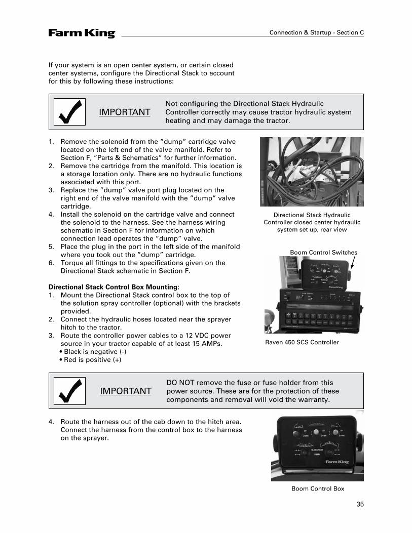
1. Remove the solenoid from the ”dump” cartridge valve located on the left end of the valve manifold. Refer to Section F, ”Parts & Schematics” for further information.
2. Remove the cartridge from the manifold. This location is a storage location only. There are no hydraulic functions associated with this port.
3. Replace the ”dump” valve port plug located on the right end of the valve manifold with the ”dump” valve cartridge.
4. Install the solenoid on the cartridge valve and connect the solenoid to the harness. See the harness wiring schematic in Section F for information on which connection lead operates the ”dump” valve.
5. Place the plug in the port in the left side of the manifold where you took out the ”dump” cartridge.
6. Torque all fittings to the specifications given on the Directional Stack schematic in Section F.
Directional Stack Control Box Mounting:1. Mount the Directional Stack control box to the top of
the solution spray controller (optional) with the brackets provided.
2. Connect the hydraulic hoses located near the sprayer hitch to the tractor.
3. Route the controller power cables to a 12 VDC power source in your tractor capable of at least 15 AMPs.
• Black is negative (-) • Red is positive (+)
Directional Stack Hydraulic Controller closed center hydraulic
system set up, rear view
IMPORTANTDO NOT remove the fuse or fuse holder from this power source. These are for the protection of these components and removal will void the warranty.
4. Route the harness out of the cab down to the hitch area. Connect the harness from the control box to the harness on the sprayer.
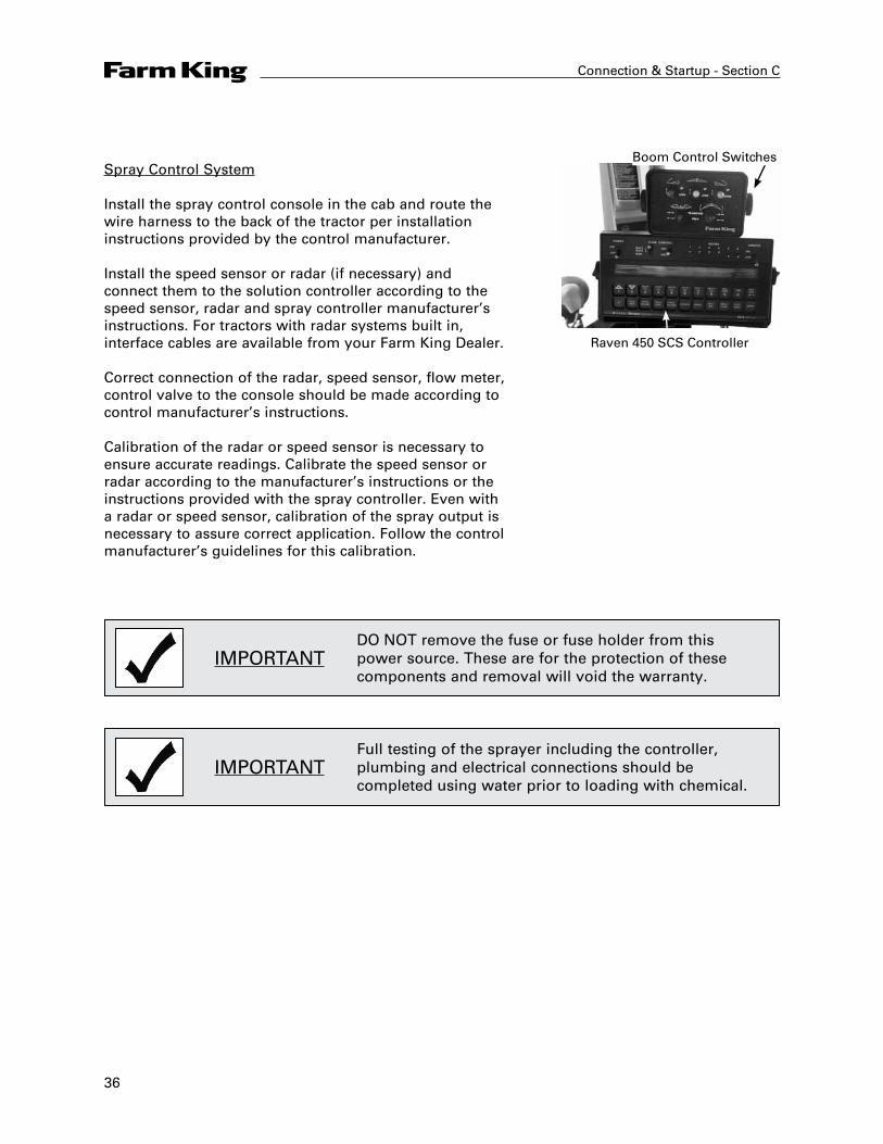
Boom Control Switches
Raven 450 SCS Controller
Boom Control Box
Connection & Startup - Section C
36
IMPORTANTDO NOT remove the fuse or fuse holder from this power source. These are for the protection of these components and removal will void the warranty.
IMPORTANTFull testing of the sprayer including the controller, plumbing and electrical connections should be completed using water prior to loading with chemical.
Spray Control System
Install the spray control console in the cab and route the wire harness to the back of the tractor per installation instructions provided by the control manufacturer.
Install the speed sensor or radar (if necessary) and connect them to the solution controller according to the speed sensor, radar and spray controller manufacturer’s instructions. For tractors with radar systems built in, interface cables are available from your Farm King Dealer.
Correct connection of the radar, speed sensor, flow meter, control valve to the console should be made according to control manufacturer’s instructions.
Calibration of the radar or speed sensor is necessary to ensure accurate readings. Calibrate the speed sensor or radar according to the manufacturer’s instructions or the instructions provided with the spray controller. Even with a radar or speed sensor, calibration of the spray output is necessary to assure correct application. Follow the control manufacturer’s guidelines for this calibration.
Boom Control Switches
Raven 450 SCS Controller
Connection & Startup - Section C
37
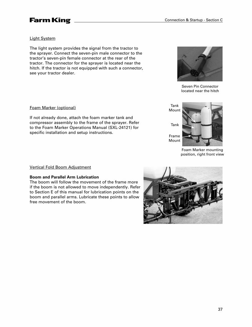
Light System
The light system provides the signal from the tractor to the sprayer. Connect the seven-pin male connector to the tractor’s seven-pin female connector at the rear of the tractor. The connector for the sprayer is located near the hitch. If the tractor is not equipped with such a connector, see your tractor dealer.
Foam Marker (optional)
If not already done, attach the foam marker tank and compressor assembly to the frame of the sprayer. Refer to the Foam Marker Operations Manual (SXL-24121) for specific installation and setup instructions.
Vertical Fold Boom Adjustment
Boom and Parallel Arm LubricationThe boom will follow the movement of the frame more if the boom is not allowed to move independently. Refer to Section E of this manual for lubrication points on the boom and parallel arms. Lubricate these points to allow free movement of the boom.
Seven Pin Connector located near the hitch
Tank Mount
Tank
Frame Mount
Foam Marker mounting position, right front view
Connection & Startup - Section C

38
NOTES:
Connection & Startup - Section C

39
StorageSection D
40
When storing the sprayer for longer periods of time, the following procedures must be followed to lessen the chance of rust and corrosion on the unit. It may be easier to perform functions 1 - 5 while the unit is connected to the tractor. This will allow for pumping and spray flushing power.
1. Make certain the inside of the tank is completely drained of chemical residue.
2. Thoroughly flush the inside of the poly tank with clean water.
3. Flush clean water through all areas of the plumbing, pumping valving and nozzle system.
4. If the sprayer will be exposed to possible freezing temperatures, the final flush of the system should be made with anti-freeze liquid.
5. Open all drain points and let as much liquid drain as possible.
6. Remove and clean the strainer(s).
7. Remove and clean nozzles. Store inside with other nozzles.
8. Check for loose hardware and fittings and tighten accordingly.
9. Replace all caps, tank lids and plug nozzle outlets prior to storage.
10. Poly tanks can become damaged when subjected to direct sunlight. For longer life of this system it is best to store it in a cool dry location or drape with a sun protective tarp.
11. Store sprayer with booms folded resting in the cradles. Coat all exposed cylinder shafts with a rust inhibitor to prevent corrosion. Verify with the manufacturers of the rust inhibitor and your tractor’s hydraulic oil that the two are compatible before use.
CAUTIONBlock and support the trailer sprayer when working on unit that has been removed from the tractor.
DANGERAll chemical contaminated rinse material must be collected and disposed of according to product label instructions and in accordance with all Local, State, and Federal Laws.
Storage - Section D
41
Maintenance, Service & TroubleshootingSection E
42
CAUTION
004775
ALWAYS WEAR
PROTECTIVE CLOTHING
GOGGLES, RESPIRATORS
AND GLOVES WHEN
HANDLING CHEMICALS
CAUTIONAGRICULTURAL CHEMICALSCAN BE DANGEROUS.IMPROPER SELECTION ORUSE CAN INJURE PERSONS,ANIMALS, PLANTS, SOILSOR OTHER PROPERTY.
TO AVOID INJURY1. SELECT THE RIGHT CHEMICAL FOR THE JOB.2. HANDLE AND APPLY IT WITH CARE. FOLLOW INSTRUCTIONS ISSUED BY THE CHEMICAL MANUFACTURER.
002438
DANGER
If any of the above inspections, or others identified, are discovered REPAIR IMMEDIATELY.Do not put this unit into operation with any questionably maintained parts. Poor performance or a hazard may occur.
Liquid Tank, Frame, and Plumbing
1. Check tank visually for obvious cuts, cracks, punctures or leaks that could contribute to tank failure.
2. Check fittings for broken parts, cracks or wear marks and potential leaks.
3. Check gaskets of the bulk head fitting located on the sump for wear or weathering.
4. Inspect valves and pump for solid connections and correct mounting.
5. Inspect the tank lids for cracks and verify they tighten securely in place.
6. Remove any debris from inside the tanks as they may become lodged in the strainer or pass into the pump.
7. Clean strainer daily, more frequently if your liquid supply is not ”free of debris”.
8. Inspect all welds and structural components for tears, bends, cracks or damage. This unit operates in a corrosive environment. Make certain corrosion is quickly removed and painted. If corrosion is deep, replace component or add adequate plating with welding operation.
IMPORTANT
Proper maintenance of the Sprayer and the tractor is critical for peak performance, reliability and accuracy of this system. The following is a guideline of the type of maintenance and servicing that should be performed on this unit. Your environment and uses may require additional maintenance and service beyond this list to assure a reliable and safe unit. The operator of this unit has ultimate responsibility to identify areas of concern and rectify them before they become a hazard or safety issue. There is no substitute for a trained, alert operator.
Maintenance, Service & Troubleshooting - Section E
DANGERTO AVOID INJURY OR DEATHKEEP EVERYONE CLEAR OFMACHINE WHEN FOLDING
OR UNFOLDING WINGS
43
WARNING
004774
KEEP HANDS AND
BODY AWAY FROM
AREAS WHICH
EJECT FLUIDS UNDER
HIGH PRESSURE
CAUTIONUSE CYLINDER LOCKUP WHEN
SERVICING OR STORING UNIT
Hydraulics
1. Inspect cylinder shafts for corrosion or damage. Repair or replace shaft to avoid hydraulic leaks or cylinder failure.
2. Inspect hydraulic hoses. Replace any hose that shows signs of wear or damage.
3. Removing hydraulic hoses for any reason requires that you plumb them back to their original position. Failure to do this may result in incorrect operation and may damage the sprayer. See Section F for the hydraulic plumbing schematic.
IMPORTANTFailure to plumb the parallel cylinders correctly may cause damage to the Henschen Suspension.
Electrical & Control System
Use of dielectric grease is strongly urged for all electrical wire connections. All connections should be greased at the beginning of the season. Poor electrical connections due to corrosion is the leading cause of failure of sprayer equipment in this environment.
Packard style connections on certain options are designed to be weather resistant. This feature greatly reduces the corrosion associated with electric connectors. Use of dielectric grease is optional on these connections.
Maintenance, Service & Troubleshooting - Section E
DANGERTO AVOID INJURY OR DEATHKEEP EVERYONE CLEAR OFMACHINE WHEN FOLDING
OR UNFOLDING WINGS
44
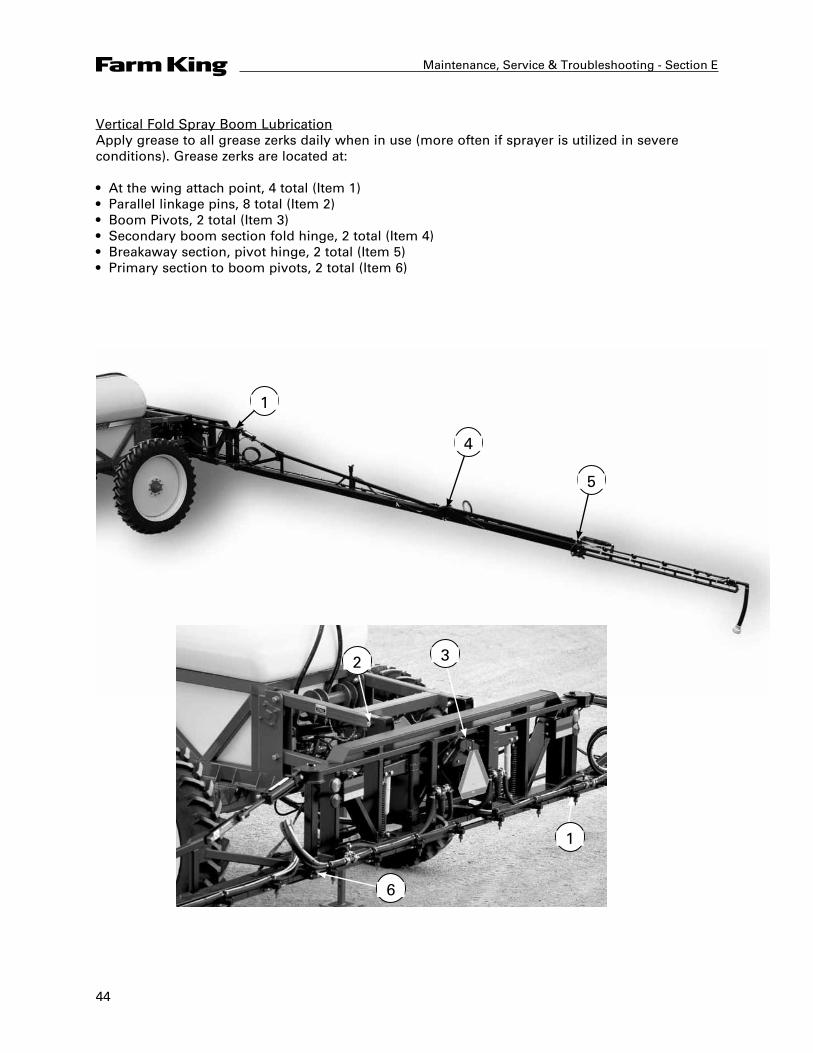
Vertical Fold Spray Boom LubricationApply grease to all grease zerks daily when in use (more often if sprayer is utilized in severe conditions). Grease zerks are located at:
• At the wing attach point, 4 total (Item 1)• Parallel linkage pins, 8 total (Item 2)• Boom Pivots, 2 total (Item 3)• Secondary boom section fold hinge, 2 total (Item 4)• Breakaway section, pivot hinge, 2 total (Item 5)• Primary section to boom pivots, 2 total (Item 6)
1
4
5
2 3
6
1
Maintenance, Service & Troubleshooting - Section E
45
Wheel Lug Nut TorqueWhen receiving your sprayer or replacing a tire, follow these steps for ensuring proper lug-nut torque:
NOTE DO NOT use undersized tires. Use the right size tires for the job and properly match tires to wheels.
NOTE DO NOT lubricate threads.
NOTE
Failure to check and maintain the proper lug nut torque could result in elongation of rim and/or broken lug-bolts. We recommend checking lug nut torque at regular maintenance intervals to ensure proper wheel tightness on your Farm King Sprayer.
1. Tighten lug nuts to correct torque specifications using a crisscross pattern.
Size Torque ft./lb 3/4”-16 UNF 250 - 265 5/8-18 Bolt 140 - 170
2. After tightening, pull the Farm King 1200 High-Clearance Sprayer approximately one (1) mile.
3. Retighten lug nuts to correct torque specs.
4. Use the sprayer, stopping after three (3) hours and again after ten (10) hours to retighten lug nuts to correct torque specifications.
5. At regular maintenance intervals recheck lug nut tightness.
Again, we recommend checking lug nut torque at regular maintenance intervals to ensure proper wheel tightness on you Farm King Sprayer.
Maintenance, Service & Troubleshooting - Section E
46
WARNING
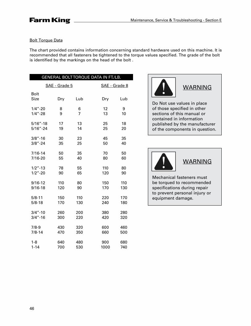
Do Not use values in place of those specified in other sections of this manual or contained in information published by the manufacturer of the components in question.
GENERAL BOLT TORQUE DATA IN FT./LB.
SAE - Grade 5 SAE - Grade 8
BoltSize
1/4”-201/4”-28
5/16”-185/16”-24
3/8”-163/8”-24
7/16-147/16-20
1/2”-131/2”-20
9/16-129/16-18
5/8-115/8-18
3/4”-103/4”-16
7/8-97/8-14
1-81-14
Dry
89
1719
3035
5055
7890
110120
150170
260300
430470
640700
Lub
67
1314
2325
3540
5565
8090
110130
200220
320350
480530
Dry
1213
2525
4550
7080
110120
150170
220240
380420
600660
9001000
Lub
910
1820
3540
5060
8090
110130
170180
280320
460500
680740
Bolt Torque Data
The chart provided contains information concerning standard hardware used on this machine. It is recommended that all fasteners be tightened to the torque values specified. The grade of the bolt is identified by the markings on the head of the bolt .
WARNING
Mechanical fasteners must be torqued to recommended specifications during repair to prevent personal injury or equipment damage.
Maintenance, Service & Troubleshooting - Section E
47
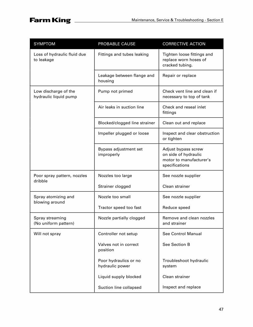
SYMPTOM PROBABLE CAUSE CORRECTIVE ACTION
Loss of hydraulic fluid due to leakage
Fittings and tubes leaking Tighten loose fittings and replace worn hoses of cracked tubing.
Leakage between flange and housing
Repair or replace
Low discharge of the hydraulic liquid pump
Pump not primed Check vent line and clean if necessary to top of tank
Air leaks in suction line Check and reseal inlet fittings
Blocked/clogged line strainer Clean out and replace
Impeller plugged or loose Inspect and clear obstruction or tighten
Bypass adjustment set improperly
Adjust bypass screw on side of hydraulic motor to manufacturer’s specifications
Poor spray pattern, nozzles dribble
Nozzles too large
Strainer clogged
See nozzle supplier
Clean strainer
Spray atomizing and blowing around
Nozzle too small
Tractor speed too fast
See nozzle supplier
Reduce speed
Spray streaming (No uniform pattern)
Nozzle partially clogged Remove and clean nozzles and strainer
Will not spray Controller not setup
Valves not in correct position
Poor hydraulics or no hydraulic power
Liquid supply blocked
Suction line collapsed
See Control Manual
See Section B
Troubleshoot hydraulic system
Clean strainer
Inspect and replace
Maintenance, Service & Troubleshooting - Section E

48
NOTES:
Maintenance, Service & Troubleshooting - Section E

49
Parts & SchematicsSection F
50
5
6
7
7
7
8
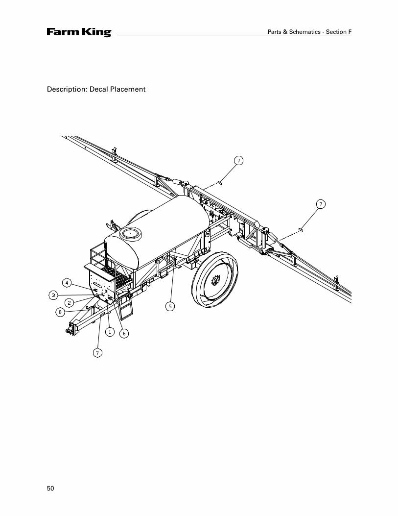
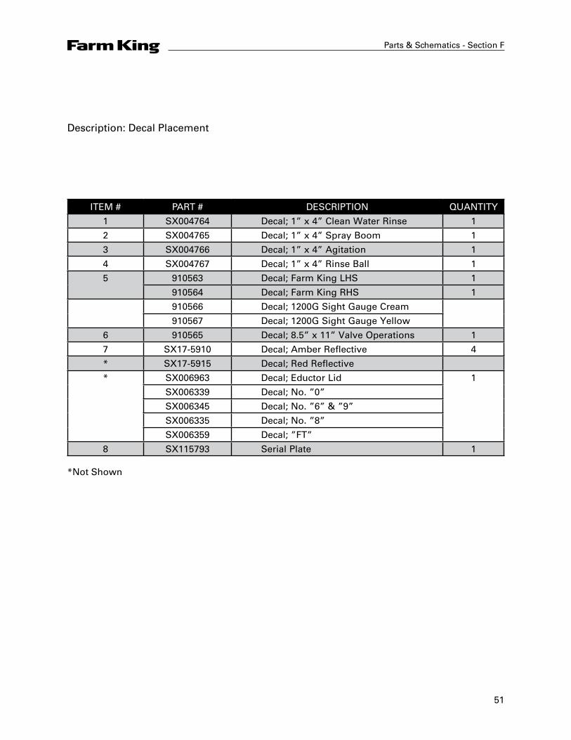
Description: Decal Placement
Parts & Schematics - Section F
51
ITEM # PART # DESCRIPTION QUANTITY
1 SX004764 Decal; 1” x 4” Clean Water Rinse 1
2 SX004765 Decal; 1” x 4” Spray Boom 1
3 SX004766 Decal; 1” x 4” Agitation 1
4 SX004767 Decal; 1” x 4” Rinse Ball 1
5 910563 Decal; Farm King LHS 1
910564 Decal; Farm King RHS 1
910566 Decal; 1200G Sight Gauge Cream
910567 Decal; 1200G Sight Gauge Yellow
6 910565 Decal; 8.5” x 11” Valve Operations 1
7 SX17-5910 Decal; Amber Reflective 4
* SX17-5915 Decal; Red Reflective
* SX006963 Decal; Eductor Lid 1
SX006339 Decal; No. ”0”
SX006345 Decal; No. ”6” & ”9”
SX006335 Decal; No. ”8”
SX006359 Decal; ”FT”
8 SX115793 Serial Plate 1
*Not Shown
Description: Decal Placement
Parts & Schematics - Section F
52
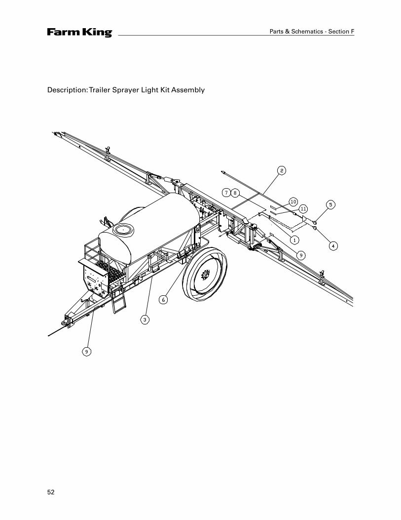
Description: Trailer Sprayer Light Kit Assembly
7 8
9
9
1011
Parts & Schematics - Section F
53
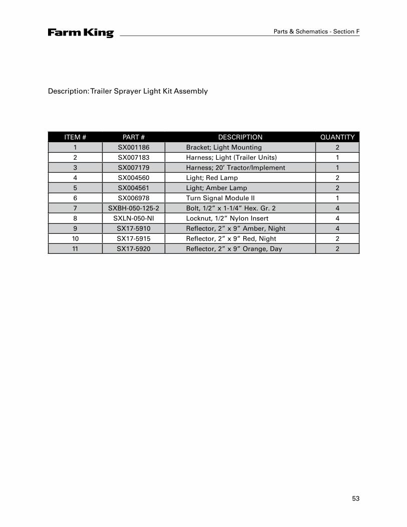
Description: Trailer Sprayer Light Kit Assembly
ITEM # PART # DESCRIPTION QUANTITY
1 SX001186 Bracket; Light Mounting 2
2 SX007183 Harness; Light (Trailer Units) 1
3 SX007179 Harness; 20’ Tractor/Implement 1
4 SX004560 Light; Red Lamp 2
5 SX004561 Light; Amber Lamp 2
6 SX006978 Turn Signal Module II 1
7 SXBH-050-125-2 Bolt, 1/2” x 1-1/4” Hex. Gr. 2 4
8 SXLN-050-NI Locknut, 1/2” Nylon Insert 4
9 SX17-5910 Reflector, 2” x 9” Amber, Night 4
10 SX17-5915 Reflector, 2” x 9” Red, Night 2
11 SX17-5920 Reflector, 2” x 9” Orange, Day 2
Parts & Schematics - Section F
54
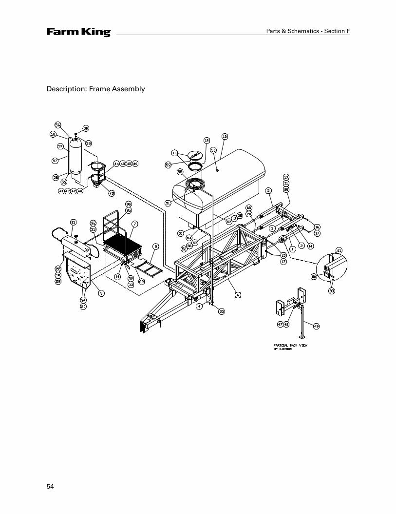
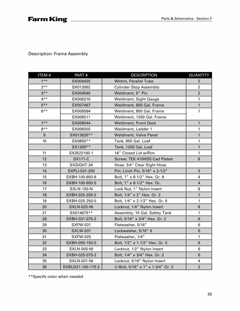
Description: Frame Assembly
Parts & Schematics - Section F
55
ITEM # PART # DESCRIPTION QUANTITY
1** SX004435 Wldmt, Parallel Tube 2
2** SX013062 Cylinder Stop Assembly 2
3** SX004540 Weldment, 6” Pin 2
4** SX006216 Weldment, Sight Gauge 1
5** SX007467 Weldment, 850 Gal. Frame 1
6** SX006584 Weldment, 850 Gal. Frame 1
SX006511 Weldment, 1200 Gal. Frame
7** SX006544 Weldment, Front Deck 1
8** SX006555 Weldment, Ladder 1 1
9 SX013626** Weldment, Valve Panel 1
10 SX0850** Tank, 850 Gal. Loaf 1
SX1200** Tank, 1200 Gal. Loaf 1
11 SX3522160-1 16” Closed Lid w/Rim 1
12 SX171-C Screw; TEK 410HSS Cad Plated 8
13 SXSIGHT-34 Hose; 3/4” Clear Sight Hose
14 SXPLI-031-250 Pin; Linch Pin, 5/16” x 2-1/2” 3
15 SXBH-100-850-8 Bolt, 1” x 8-1/2” Hex. Gr. 8 4
16 SXBH-100-650-5 Bolt, 1” x 6-1/2” Hex. Gr. 4
17 SXLN-100-N Lock Nut, 1” Nylon Insert 8
18 SXBH-025-200-2 Bolt, 1/4” x 2” Hex. Gr. 2 1
19 SXBH-025-250-5 Bolt, 1/4” x 2-1/2” Hex. Gr. 5 1
20 SXLN-025-NI Locknut, 1/4” Nylon Insert 8
21 SX014675** Assembly; 15 Gal. Safety Tank 1
28 SXBH-031-075-2 Bolt, 5/16” x 3/4” Hex. Gr. 2 6
29 SXFW-031 Flatwasher, 5/16” 6
30 SXLW-031 Lockwasher, 5/16” 6 6
31 SXFW-025 Flatwasher, 1/4” 1
32 SXBH-050-150-5 Bolt, 1/2” x 1-1/2” Hex. Gr. 5 6
33 SXLN-050-NI Locknut, 1/2” Nylon Insert 6
34 SXBH-025-075-2 Bolt, 1/4” x 3/4” Hex. Gr. 2 6
35 SXLN-031-NI Locknut, 5/16” Nylon Insert 4
36 SXBU031-100-175-2 U-Bolt, 5/16” x 1” x 1-3/4” Gr. 2 2
**Specify color when needed
Description: Frame Assembly
Parts & Schematics - Section F
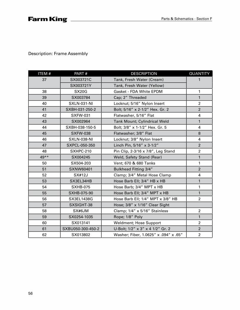
56
ITEM # PART # DESCRIPTION QUANTITY
37 SX003721C Tank, Fresh Water (Cream) 1
SX003721Y Tank, Fresh Water (Yellow)
38 SX20G Gasket - FDA White EPDM 1
39 SX003784 Cap; 2” Threaded 1
40 SXLN-031-NI Locknut; 5/16” Nylon Insert 2
41 SXBH-031-250-2 Bolt; 5/16” x 2-1/2” Hex. Gr. 2 2
42 SXFW-031 Flatwasher, 5/16” Flat 4
43 SX002964 Tank Mount; Cylindrical Weld 1
44 SXBH-038-150-5 Bolt; 3/8” x 1-1/2” Hex. Gr. 5 4
45 SXFW-038 Flatwasher; 3/8” Flat 8
46 SXLN-038-NI Locknut; 3/8” Nylon Insert 4
47 SXPCL-050-350 Linch Pin, 5/16” x 3-1/2” 2
48 SXHPC-210 Pin Clip, 2-3/16 x 7/8”, Leg Stand 2
49** SX004245 Weld, Safety Stand (Rear) 1
50 SX504-203 Vent; 670 & 680 Tanks 1
51 SXNW60401 Bulkhead Fitting 3/4” 2
52 SX#12J Clamp; 3/4” Metal Hose Clamp 4
53 SX3EL34HB Hose Barb Ell; 3/4” HB x HB 1
54 SXHB-075 Hose Barb; 3/4” MPT x HB 1
55 SXHB-075-90 Hose Barb Ell; 3/4” MPT x HB 1
56 SX3EL1438G Hose Barb Ell; 1/4” MPT x 3/8” HB 2
57 SXSIGHT-38 Hose; 3/8” x 1/16” Clear Sight
58 SX#6JM Clamp; 1/4” x 5/16” Stainless 2
59 SX0254-1035 Rope; 1/8” Poly 1
60 SX013141 Weldment; Hose Support 2
61 SXBU050-300-450-2 U-Bolt; 1/2” x 3” x 4 1/2” Gr. 2 2
62 SX013802 Washer; Fiber, 1.0625” x .094” x .65” 2
Description: Frame Assembly
Parts & Schematics - Section F
57
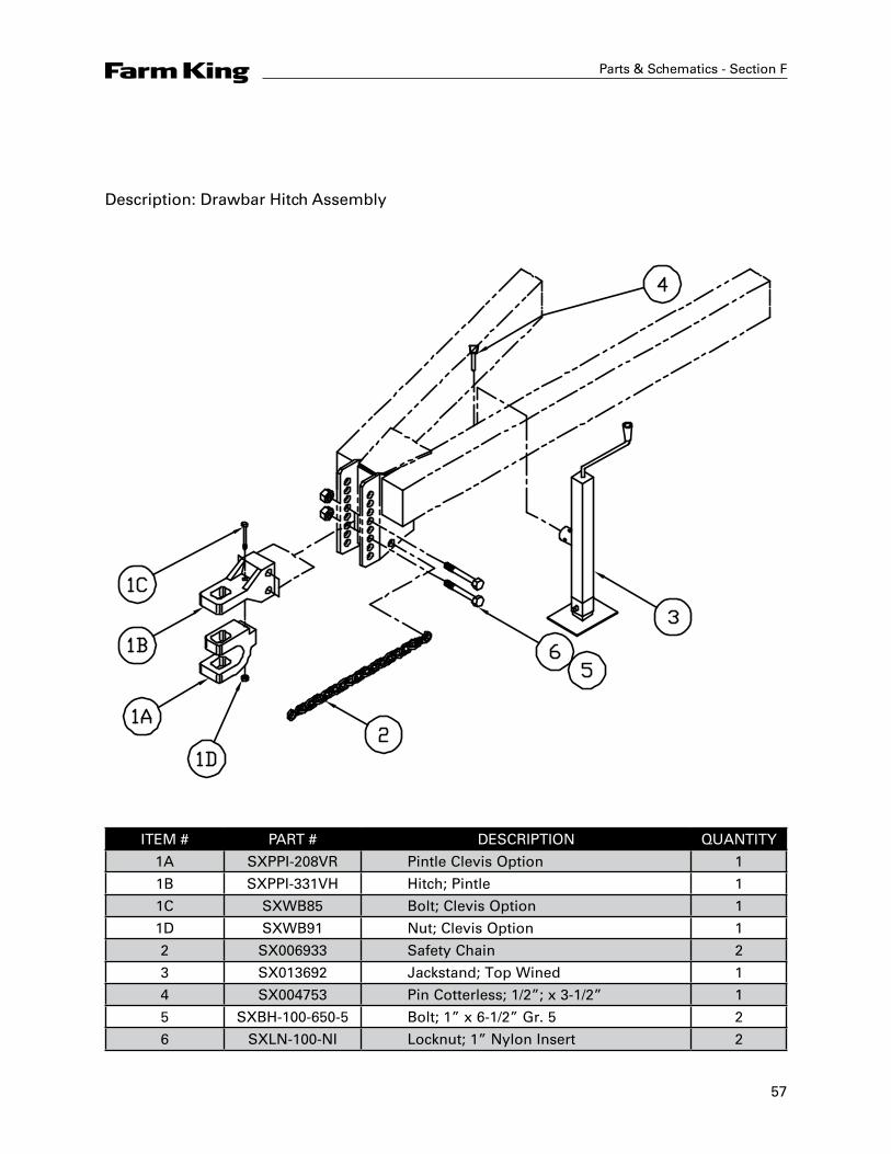
ITEM # PART # DESCRIPTION QUANTITY
1A SXPPI-208VR Pintle Clevis Option 1
1B SXPPI-331VH Hitch; Pintle 1
1C SXWB85 Bolt; Clevis Option 1
1D SXWB91 Nut; Clevis Option 1
2 SX006933 Safety Chain 2
3 SX013692 Jackstand; Top Wined 1
4 SX004753 Pin Cotterless; 1/2”; x 3-1/2” 1
5 SXBH-100-650-5 Bolt; 1” x 6-1/2” Gr. 5 2
6 SXLN-100-NI Locknut; 1” Nylon Insert 2
Description: Drawbar Hitch Assembly
Parts & Schematics - Section F
58
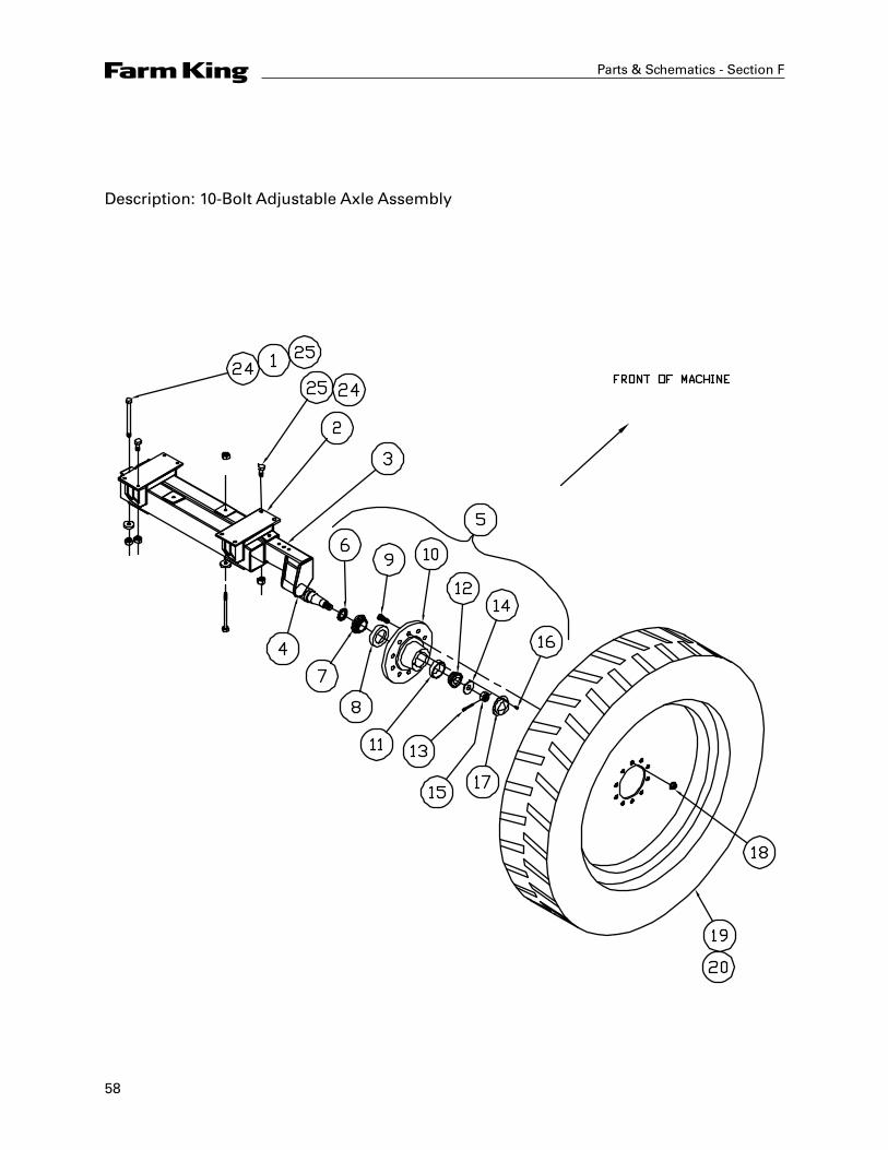
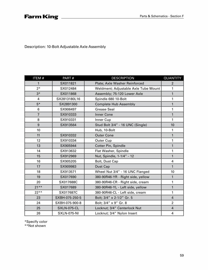
Description: 10-Bolt Adjustable Axle Assembly
Parts & Schematics - Section F
59
ITEM # PART # DESCRIPTION QUANTITY
1 SX011821 Plate; Axle Washer Reinforced 2
2* SX012484 Weldment; Adjustable Axle Tube Mount 1
3* SX011868 Assembly; 75-120 Lower Axle 1
4 SX2813180L16 Spindle 680 10-Bolt 1
5* SX2891300 Complete Hub Assembly 1
6 SX906497 Grease Seal 1
7 SX910333 Inner Cone 1
8 SX910331 Inner Cup 1
9 SX913564 Stud Bolt 3/4” - 16 UNC (Single) 10
10 Hub, 10-Bolt 1
11 SX910332 Outer Cone 1
12 SX910334 Outer Cup 1
13 SX905944 Cotter Pin, Spindle 1
14 SX913632 Flat Washer, Spindle 1
15 SX912969 Nut, Spindle, 1-1/4” - 12 1
16 SX905205 Bolt, Dust Cap 4
17 SX909983 Dust Cap 1
18 SX913571 Wheel Nut 3/4” - 16 UNC Flanged 10
19 SX017690 380-90R46-YR - Right side, yellow 1
20 SX017688C 380-90R46-CR - Right side, cream 1
21** SX017689 380-90R46-YL - Left side, yellow 1
22** SX017687C 380-90R46-CL - Left side, cream 1
23 SXBH-075-250-5 Bolt; 3/4” x 2-1/2” Gr. 5 4
24 SXBH-075-900-8 Bolt; 3/4” x 9” Gr. 8 2
25 SXLN-075-CL Locknut; 3/4” Centerlock Nut 4
26 SXLN-075-NI Locknut; 3/4” Nylon Insert 4
*Specify color**Not shown
Description: 10-Bolt Adjustable Axle Assembly
Parts & Schematics - Section F
60
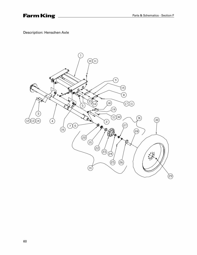
Description: Henschen Axle
Parts & Schematics - Section F
61
ITEM # PART # DESCRIPTION QUANTITY
1* SX013349 Weldment; Axle Mount 1
2 SX013325 Tube; Machined Link 4
3 SX013337 Bumper; Axle 2
4* SX013346 Weldment; 120” Henschen Axle (Shown) 1
SX015171 Weldment; 88” Henschen Axle 1
SX015654 Weldment; 110” Henschen Axle 1
5 SX013348 Weldment; Pivot Pin 2
6 SXAB-12 Rod End; 3/4” LH High capacity 4
7 SXNUT-075-JFL Nut; 3/4”-16 Jam Nut Fine; Left 4
8 SX013331 Weldment; Long Link 2
9 SX013329B Plate; Long Link Pntd 2
10 SXBH-075-225-5 Bolt, Hex, 3/4” x 2-1/4” Gr. 5 8
11 SXLN-075-CL Locknut, 3/4” Centerlock 16
12 SXBF-038-150-C Bolt, 3/8” x 1-1/2” Flathead C.S. 4
13 SXFW-038 Flatwasher, 3/8” 4
14 SXNUT-038 Nut, 3/8” 4
15 SX013310 Bushing, Spr Stl, 1” OD x 3/4” ID x 1” Lg 4
16 SX013311 Bushing, Stl, 1-1/2” OD x 1-1/4” ID x 1.5” Lg 4
17 SXBH-075-300-5 Bolt, Hex, 3/4” x 3” Gr. 5 4
18 SXAM-12 Rod End; 3/4” RH High Capacity 4
19 SXNUT-075-JF Nut, 3/4”, JAM, Fine 4
20 SX906497 Grease Seal 2
21 SX910333 Inner Cone 2
22 SX910331 Inner Cup 2
23 Hub, 10-Bolt 2
24 SX910334 Outer Cup 2
25 SX905944 Cotter Pin, Spindle 2
26 SX909983 Dust Cap 2
27 SX910332 Outer Cone 2
28 SX905205 Bolt, Dust Cap 8
29 SX913571 Nut, Spindle, 1-1/4”-12 20
30 SX017688C 380-90R46-CR - Right side, cream 1
SX017690 380-90R46-YR - Right side, yellow
SX017687C 380-90R46-CL - Left side, cream
SX017689 380-90R46-YL - Left side, yellow
31 SX2891300 Assembly; 10 Bolt Hub 2
32 SXBH-075-400-5 Bolt; 3/4” x 4” Gr. 5 4
33 SXBH-038-100-5 Bolt; 3/8” x 1” Gr. 5 2
34 SXLN-038-CL Locknut, 3/8” Centerlock 2
*Specify color
Description: Henschen Axle
Parts & Schematics - Section F
62
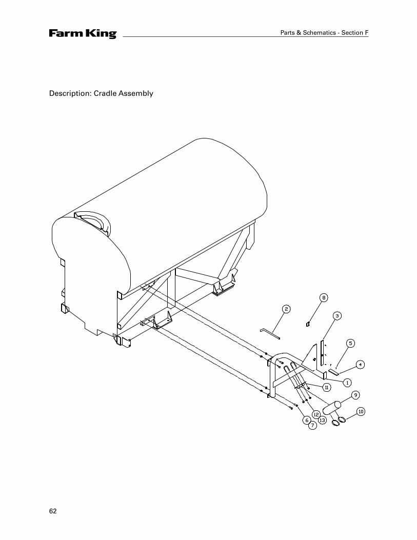
Description: Cradle Assembly
Parts & Schematics - Section F
63
ITEM # PART # DESCRIPTION QUANTITY
1* SX012646 Cradle; 1200 Front Fold Boom 1
2 SX013402 Rod; Wing Cradle Slide 1
3 SX012119 Black Plastic For 1200 1
4 SX012120 Black Plastic For 1200 1
5 SX171-C Screw; TEC 410HSS Cad Plated 5
6 SXBH-050-150-5 Bolt; 1/2” x 1-1/2” Grade 5 4
7 SXLN-050-NI Locknut; 1/2” Nylon Insert 4
8 SXPLI-031-250 Pin; Linch Pin; 5/16” x 2-1/2” 1
9** SX013049 Tube; Manual Storage 1
10** SX#64J Clamp; 4” x 1/2” Stainless 2
11** SX014159 Manual Bracket, Bent with Holes 1
12** SXBU031-150-350-2 U-Bolt; 5/16” x 1-1/2” x 3-1/2” Gr. 2 2
13** SXLN-031-NI Locknut; 5/16” Nylon Insert 4
*Specify color**Used on one side only. Quantities listed are per side
Description: Cradle Assembly
Parts & Schematics - Section F
64
30
31
3132 32
33
33
34
35 35
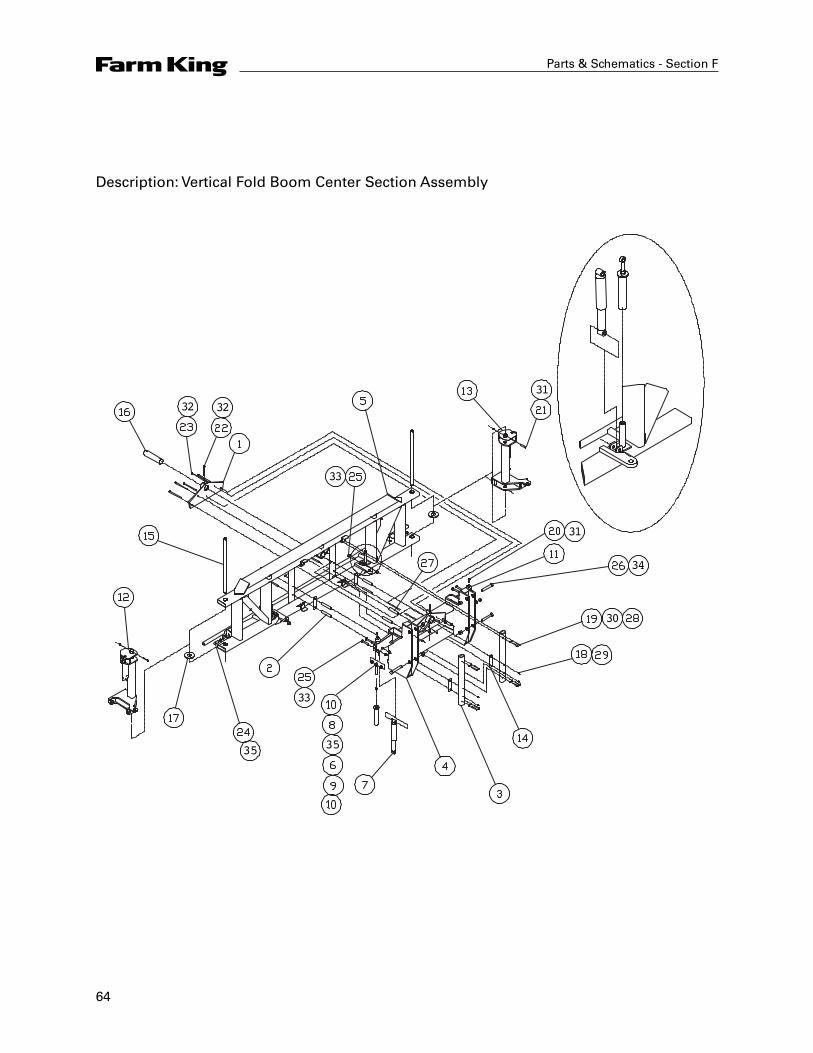
Description: Vertical Fold Boom Center Section Assembly
Parts & Schematics - Section F
65
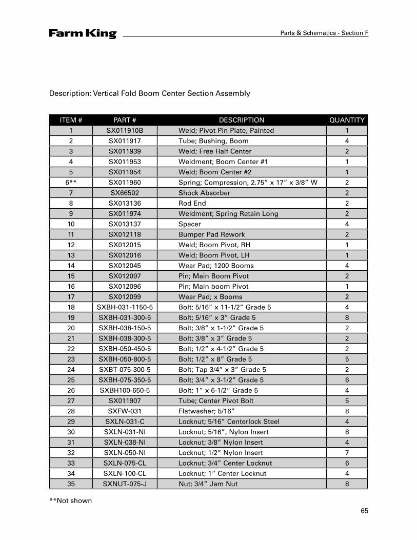
ITEM # PART # DESCRIPTION QUANTITY
1 SX011910B Weld; Pivot Pin Plate, Painted 1
2 SX011917 Tube; Bushing, Boom 4
3 SX011939 Weld; Free Half Center 2
4 SX011953 Weldment; Boom Center #1 1
5 SX011954 Weld; Boom Center #2 1
6** SX011960 Spring; Compression, 2.75” x 17” x 3/8” W 2
7 SX66502 Shock Absorber 2
8 SX013136 Rod End 2
9 SX011974 Weldment; Spring Retain Long 2
10 SX013137 Spacer 4
11 SX012118 Bumper Pad Rework 2
12 SX012015 Weld; Boom Pivot, RH 1
13 SX012016 Weld; Boom Pivot, LH 1
14 SX012045 Wear Pad; 1200 Booms 4
15 SX012097 Pin; Main Boom Pivot 2
16 SX012096 Pin; Main boom Pivot 1
17 SX012099 Wear Pad; x Booms 2
18 SXBH-031-1150-5 Bolt; 5/16” x 11-1/2” Grade 5 4
19 SXBH-031-300-5 Bolt; 5/16” x 3” Grade 5 8
20 SXBH-038-150-5 Bolt; 3/8” x 1-1/2” Grade 5 2
21 SXBH-038-300-5 Bolt; 3/8” x 3” Grade 5 2
22 SXBH-050-450-5 Bolt; 1/2” x 4-1/2” Grade 5 2
23 SXBH-050-800-5 Bolt; 1/2” x 8” Grade 5 5
24 SXBT-075-300-5 Bolt; Tap 3/4” x 3” Grade 5 2
25 SXBH-075-350-5 Bolt; 3/4” x 3-1/2” Grade 5 6
26 SXBH100-650-5 Bolt; 1” x 6-1/2” Grade 5 4
27 SX011907 Tube; Center Pivot Bolt 5
28 SXFW-031 Flatwasher; 5/16” 8
29 SXLN-031-C Locknut; 5/16” Centerlock Steel 4
30 SXLN-031-NI Locknut; 5/16”, Nylon Insert 8
31 SXLN-038-NI Locknut; 3/8” Nylon Insert 4
32 SXLN-050-NI Locknut; 1/2” Nylon Insert 7
33 SXLN-075-CL Locknut; 3/4” Center Locknut 6
34 SXLN-100-CL Locknut; 1” Center Locknut 4
35 SXNUT-075-J Nut; 3/4” Jam Nut 8
**Not shown
Description: Vertical Fold Boom Center Section Assembly
Parts & Schematics - Section F
66
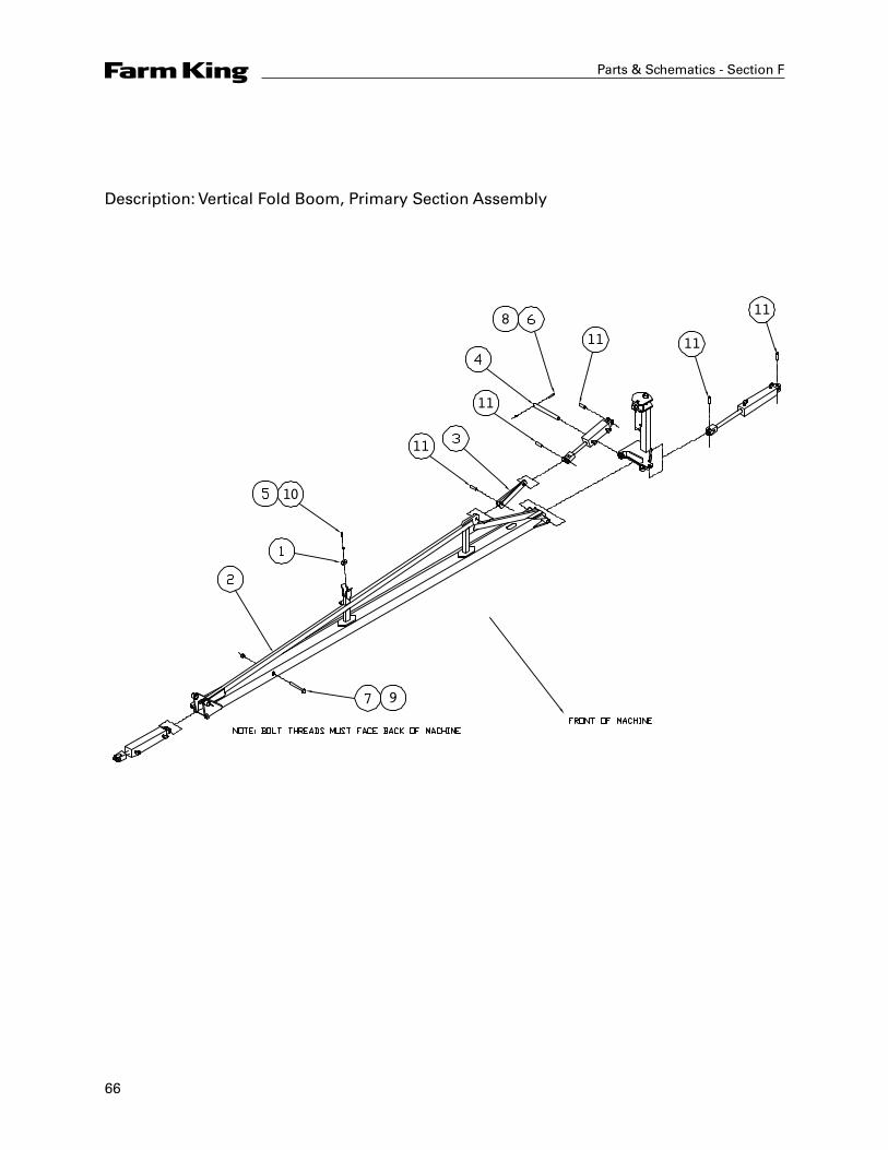
Description: Vertical Fold Boom, Primary Section Assembly
7
8
9
10
11
11
11 11
11
Parts & Schematics - Section F
67
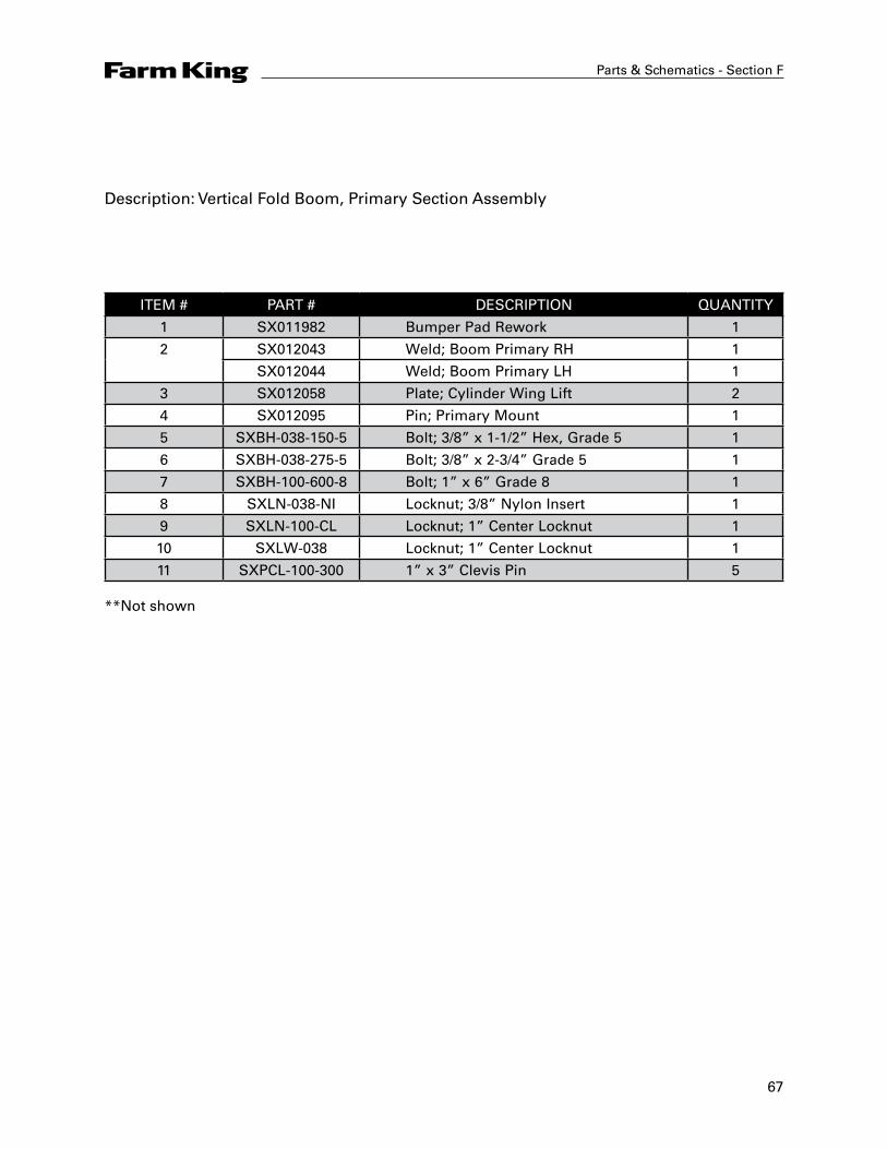
Description: Vertical Fold Boom, Primary Section Assembly
ITEM # PART # DESCRIPTION QUANTITY
1 SX011982 Bumper Pad Rework 1
2 SX012043 Weld; Boom Primary RH 1
SX012044 Weld; Boom Primary LH 1
3 SX012058 Plate; Cylinder Wing Lift 2
4 SX012095 Pin; Primary Mount 1
5 SXBH-038-150-5 Bolt; 3/8” x 1-1/2” Hex, Grade 5 1
6 SXBH-038-275-5 Bolt; 3/8” x 2-3/4” Grade 5 1
7 SXBH-100-600-8 Bolt; 1” x 6” Grade 8 1
8 SXLN-038-NI Locknut; 3/8” Nylon Insert 1
9 SXLN-100-CL Locknut; 1” Center Locknut 1
10 SXLW-038 Locknut; 1” Center Locknut 1
11 SXPCL-100-300 1” x 3” Clevis Pin 5
**Not shown
Parts & Schematics - Section F
68
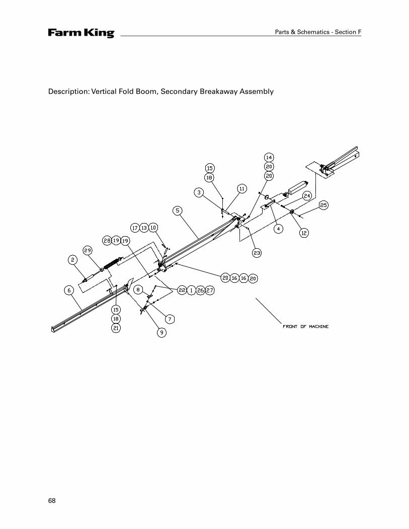
Description: Vertical Fold Boom, Secondary Breakaway Assembly
Parts & Schematics - Section F
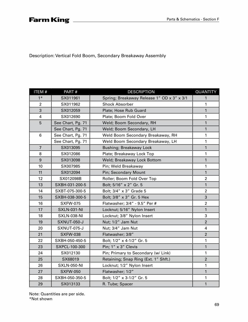
69
ITEM # PART # DESCRIPTION QUANTITY
1* SX011961 Spring; Breakaway Release 1” OD x 3” x 3/1 1
2 SX011962 Shock Absorber 1
3 SX012059 Plate; Hose Rub Guard 1
4 SX012690 Plate; Boom Fold Over 1
5 See Chart, Pg. 71 Weld; Boom Secondary, RH 1
See Chart, Pg. 71 Weld; Boom Secondary, LH 1
6 See Chart, Pg. 71 Weld Boom Secondary Breakaway, RH 1
See Chart, Pg. 71 Weld Boom Secondary Breakaway, LH 1
7 SX013095 Bushing; Breakaway Lock 1
8 SX012086 Plate; Breakaway Lock Top 1
9 SX013098 Weld; Breakaway Lock Bottom 1
10 SX007985 Pin; Weld Breakaway 1
11 SX012094 Pin; Secondary Mount 1
12 SX012098B Roller; Boom Fold Over Top 2
13 SXBH-031-200-5 Bolt; 5/16” x 2” Gr. 5 1
14 SXBT-075-300-5 Bolt; 3/4” x 3” Grade 5 2
15 SXBH-038-300-5 Bolt; 3/8” x 3” Gr. 5 Hex 3
16 SXFW-075 Flatwasher; 3/4” - 9.5” Per # 2
17 SXLN-031-NI Locknut; 5/16” Nylon Insert 1
18 SXLN-038-NI Locknut; 3/8” Nylon Insert 3
19 SXNUT-050-J Nut; 1/2” Jam Nut 2
20 SXNUT-075-J Nut; 3/4” Jam Nut 4
21 SXFW-038 Flatwasher; 3/8” 2
22 SXBH-050-450-5 Bolt; 1/2” x 4-1/2” Gr. 5 1
23 SXPCL-100-300 Pin; 1” x 3” Clevis 1
24 SX012130 Pin; Primary to Secondary (w/ Link) 1
25 SX68019 Retaining; Snap Ring (Ext. 1” Shft.) 2
26 SXLN-050-NI Locknut; 1/2” Nylon Insert 1
27 SXFW-050 Flatwasher; 1/2” 1
28 SXBH-050-350-5 Bolt; 1/2” x 3-1/2” Gr. 5 1
29 SX013133 R. Tube; Spacer 1
Note: Quantities are per side.*Not shown
Description: Vertical Fold Boom, Secondary Breakaway Assembly
Parts & Schematics - Section F
70
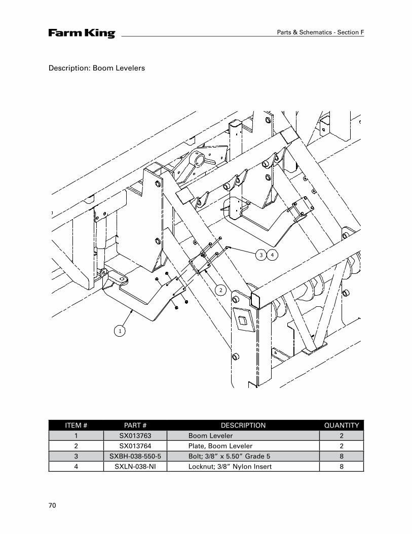
Description: Boom Levelers
ITEM # PART # DESCRIPTION QUANTITY
1 SX013763 Boom Leveler 2
2 SX013764 Plate, Boom Leveler 2
3 SXBH-038-550-5 Bolt; 3/8” x 5.50” Grade 5 8
4 SXLN-038-NI Locknut; 3/8” Nylon Insert 8
Parts & Schematics - Section F
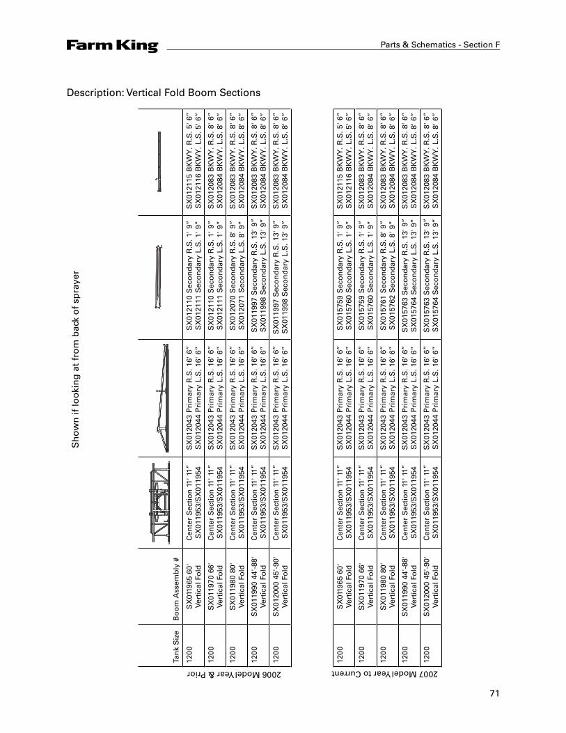
71
Parts & Schematics - Section F
Tan
k S
ize
Bo
om
Ass
emb
ly #
1200
SX
0119
65 6
0'
Vert
ical
Fo
ldC
ente
r S
ecti
on
11'
11”
SX
0119
53/S
X01
1954
SX
0120
43 P
rim
ary
R.S
. 16'
6”
SX
0120
44 P
rim
ary
L.S
. 16'
6”
SX
0121
10 S
eco
nd
ary
R.S
. 1' 9
”S
X01
2111
Sec
on
dar
y L.
S. 1
' 9”
SX
0121
15 B
KW
Y. R
.S. 5
' 6”
SX
0121
16 B
KW
Y. L
.S. 5
' 6”
1200
SX
0119
70 6
6'Ve
rtic
al F
old
Cen
ter
Sec
tio
n 1
1' 1
1”S
X01
1953
/SX
0119
54S
X01
2043
Pri
mar
y R
.S. 1
6' 6
”S
X01
2044
Pri
mar
y L.
S. 1
6' 6
”S
X01
2110
Sec
on
dar
y R
.S. 1
' 9”
SX
0121
11 S
eco
nd
ary
L.S
. 1' 9
”S
X01
2083
BK
WY
. R.S
. 8' 6
”S
X01
2084
BK
WY
. L.S
. 8' 6
”
1200
SX
0119
80 8
0'Ve
rtic
al F
old
Cen
ter
Sec
tio
n 1
1' 1
1”S
X01
1953
/SX
0119
54S
X01
2043
Pri
mar
y R
.S. 1
6' 6
”S
X01
2044
Pri
mar
y L.
S. 1
6' 6
”S
X01
2070
Sec
on
dar
y R
.S. 8
' 9”
SX
0120
71 S
eco
nd
ary
L.S
. 8' 9
”S
X01
2083
BK
WY
. R.S
. 8' 6
”S
X01
2084
BK
WY
. L.S
. 8' 6
”
1200
SX
0119
90 4
4'-8
8'Ve
rtic
al F
old
Cen
ter
Sec
tio
n 1
1' 1
1”S
X01
1953
/SX
0119
54S
X01
2043
Pri
mar
y R
.S. 1
6' 6
”S
X01
2044
Pri
mar
y L.
S. 1
6' 6
”S
X01
1997
Sec
on
dar
y R
.S. 1
3' 9
” S
X01
1998
Sec
on
dar
y L.
S. 1
3' 9
”S
X01
2083
BK
WY
. R.S
. 8' 6
”S
X01
2084
BK
WY
. L.S
. 8' 6
”
1200
SX
0120
00 4
5'-9
0'Ve
rtic
al F
old
Cen
ter
Sec
tio
n 1
1' 1
1”S
X01
1953
/SX
0119
54S
X01
2043
Pri
mar
y R
.S. 1
6' 6
”S
X01
2044
Pri
mar
y L.
S. 1
6' 6
”S
X01
1997
Sec
on
dar
y R
.S. 1
3' 9
”S
X01
1998
Sec
on
dar
y L.
S. 1
3' 9
”S
X01
2083
BK
WY
. R.S
. 8' 6
”S
X01
2084
BK
WY
. L.S
. 8' 6
”
2006 Model Year & Prior
1200
SX
0119
65 6
0'Ve
rtic
al F
old
Cen
ter
Sec
tio
n 1
1' 1
1”S
X01
1953
/SX
0119
54S
X01
2043
Pri
mar
y R
.S. 1
6' 6
”S
X01
2044
Pri
mar
y L.
S. 1
6' 6
”S
X01
5759
Sec
on
dar
y R
.S. 1
' 9”
SX
0157
60 S
eco
nd
ary
L.S
. 1' 9
”S
X01
2115
BK
WY
. R.S
. 5' 6
”S
X01
2116
BK
WY
. L.S
. 5' 6
”
1200
SX
0119
70 6
6'Ve
rtic
al F
old
Cen
ter
Sec
tio
n 1
1' 1
1”S
X01
1953
/SX
0119
54S
X01
2043
Pri
mar
y R
.S. 1
6' 6
”S
X01
2044
Pri
mar
y L.
S. 1
6' 6
”S
X01
5759
Sec
on
dar
y R
.S. 1
' 9”
SX
0157
60 S
eco
nd
ary
L.S
. 1' 9
”S
X01
2083
BK
WY
. R.S
. 8' 6
”S
X01
2084
BK
WY
. L.S
. 8' 6
”
1200
SX
0119
80 8
0'Ve
rtic
al F
old
Cen
ter
Sec
tio
n 1
1' 1
1”S
X01
1953
/SX
0119
54S
X01
2043
Pri
mar
y R
.S. 1
6' 6
”S
X01
2044
Pri
mar
y L.
S. 1
6' 6
”S
X01
5761
Sec
on
dar
y R
.S. 8
' 9”
SX
0157
62 S
eco
nd
ary
L.S
. 8' 9
”S
X01
2083
BK
WY
. R.S
. 8' 6
”S
X01
2084
BK
WY
. L.S
. 8' 6
”
1200
SX
0119
90 4
4'-8
8'Ve
rtic
al F
old
Cen
ter
Sec
tio
n 1
1' 1
1”S
X01
1953
/SX
0119
54S
X01
2043
Pri
mar
y R
.S. 1
6' 6
”S
X01
2044
Pri
mar
y L.
S. 1
6' 6
”S
X01
5763
Sec
on
dar
y R
.S. 1
3' 9
” S
X01
5764
Sec
on
dar
y L.
S. 1
3' 9
”S
X01
2083
BK
WY
. R.S
. 8' 6
”S
X01
2084
BK
WY
. L.S
. 8' 6
”
1200
SX
0120
00 4
5'-9
0'Ve
rtic
al F
old
Cen
ter
Sec
tio
n 1
1' 1
1”S
X01
1953
/SX
0119
54S
X01
2043
Pri
mar
y R
.S. 1
6' 6
”S
X01
2044
Pri
mar
y L.
S. 1
6' 6
”S
X01
5763
Sec
on
dar
y R
.S. 1
3' 9
”S
X01
5764
Sec
on
dar
y L.
S. 1
3' 9
”S
X01
2083
BK
WY
. R.S
. 8' 6
”S
X01
2084
BK
WY
. L.S
. 8' 6
”
2007 Model Year to Current
Description: Vertical Fold Boom Sections
Sh
ow
n if
loo
kin
g a
t fr
om
bac
k o
f sp
raye
r
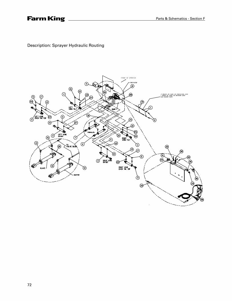
72
Description: Sprayer Hydraulic Routing
Parts & Schematics - Section F
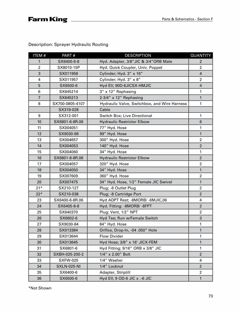
73
ITEM # PART # DESCRIPTION QUANTITY
1 SX6400-6-8 Hyd. Adapter, 3/8”JIC & 3/4”ORB Male 2
2 SX8010-15P Hyd. Quick Coupler, Univ. Poppet 2
3 SX011958 Cylinder; Hyd. 3” x 16” 4
4 SX011957 Cylinder; Hyd. 3” x 8” 2
5 SX6500-6 Hyd Ell; 90D-6JICSX-HMJIC 4
6 SX645214 3” x 12” Rephasing 1
7 SX645213 2-3/4” x 12” Rephasing 1
8 SX700-0805-4107 Hydraulic Valve, Switchbox, and Wire Harness 1
SX319-028 Cable
9 SX312-001 Switch Box; Live Directional 1
10 SX6801-6-8R.06 Hydraulic Restrictor Elbow 6
11 SX004051 77” Hyd. Hose 1
12 SX9030-99 99” Hyd. Hose 1
13 SX004657 300” Hyd. Hose 2
14 SX004053 140” Hyd. Hose 2
15 SX004060 34” Hyd. Hose 1
16 SX6801-8-8R.06 Hydraulic Restrictor Elbow 2
17 SX004057 320” Hyd. Hose 2
18 SX004050 34” Hyd. Hose 1
19 SX007609 360” Hyd. Hose 2
20 SX007475 34” Hyd. Hose, 1/2” Female JIC Swivel 1
21* SX210-127 Plug; -6 Outlet Plug 2
22* SX210-038 Plug; -8 Cartridge Port 2
23 SX6400-6-8R.06 Hyd ADPT Rest; -8MORB/ -6MJIC,06 4
24 SX6405-8-8 Hyd. Fitting: -8MORB/ -8FPT 2
25 SX640370 Plug; Vent, 1/2” NPT 2
26 SX6602-6 Hyd Tee; Run w/Female Switch 3
27 SX9030-84 84” Hyd. Hose 1
28 SX013384 Orifice, Drop-In, -04 .050” Hole 1
29 SX013644 Flow Divider 1
30 SX013645 Hyd Hose; 3/8” x 16’ JICX-FEM 1
31 SX6801-6 Hyd Fitting; 9/16” ORB x 3/8” JIC 1
32 SXBH-025-200-2 1/4” x 2.00” Bolt 2
33 SXFW-025 1/4” Washer 4
34 SXLN-025-NI 1/4” Locknut 2
35 SX6400-6 Adapter, Striptill 2
36 SX6500-6 Hyd Ell; 9 OD-6 JIC x .-6 JIC 1
*Not Shown
Description: Sprayer Hydraulic Routing
Parts & Schematics - Section F
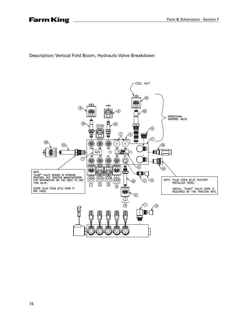
74
Description: Vertical Fold Boom, Hydraulic Valve Breakdown
Parts & Schematics - Section F
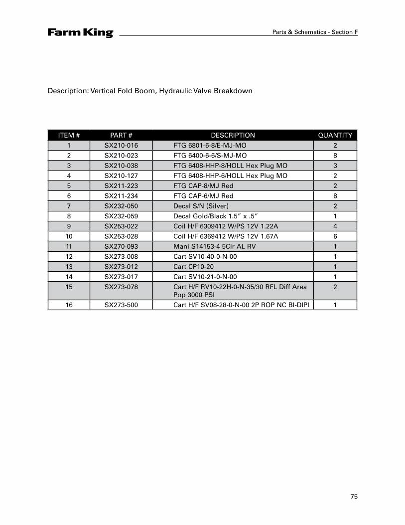
75
Description: Vertical Fold Boom, Hydraulic Valve Breakdown
ITEM # PART # DESCRIPTION QUANTITY
1 SX210-016 FTG 6801-6-8/E-MJ-MO 2
2 SX210-023 FTG 6400-6-6/S-MJ-MO 8
3 SX210-038 FTG 6408-HHP-8/HOLL Hex Plug MO 3
4 SX210-127 FTG 6408-HHP-6/HOLL Hex Plug MO 2
5 SX211-223 FTG CAP-8/MJ Red 2
6 SX211-234 FTG CAP-6/MJ Red 8
7 SX232-050 Decal S/N (Silver) 2
8 SX232-059 Decal Gold/Black 1.5” x .5” 1
9 SX253-022 Coil H/F 6309412 W/PS 12V 1.22A 4
10 SX253-028 Coil H/F 6369412 W/PS 12V 1.67A 6
11 SX270-093 Mani S14153-4 5Cir AL RV 1
12 SX273-008 Cart SV10-40-0-N-00 1
13 SX273-012 Cart CP10-20 1
14 SX273-017 Cart SV10-21-0-N-00 1
15 SX273-078 Cart H/F RV10-22H-0-N-35/30 RFL Diff Area Pop 3000 PSI
2
16 SX273-500 Cart H/F SV08-28-0-N-00 2P ROP NC BI-DIPI 1
Parts & Schematics - Section F
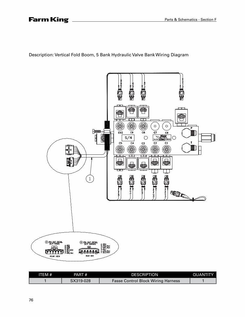
76
Description: Vertical Fold Boom, 5 Bank Hydraulic Valve Bank Wiring Diagram
ITEM # PART # DESCRIPTION QUANTITY
1 SX319-028 Fasse Control Block Wiring Harness 1
Parts & Schematics - Section F

77
THIS PAGE INTENTIONALLY LEFT OPEN
Parts & Schematics - Section F
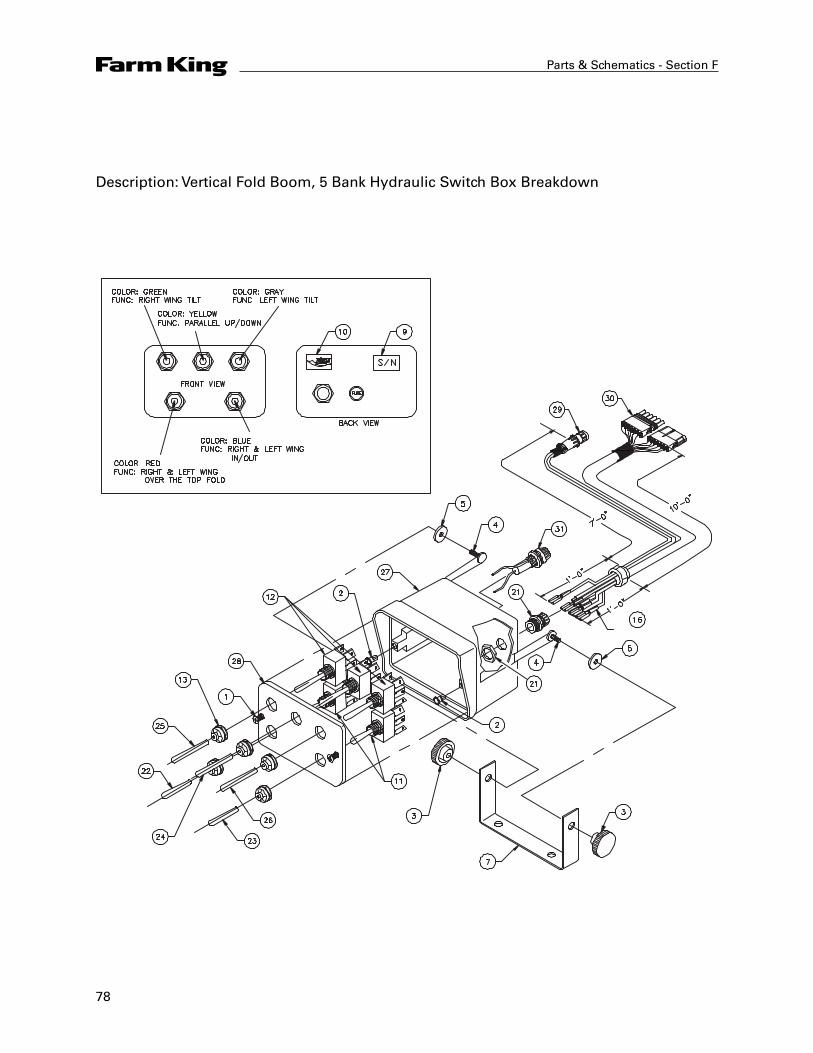
78
Description: Vertical Fold Boom, 5 Bank Hydraulic Switch Box Breakdown
Parts & Schematics - Section F
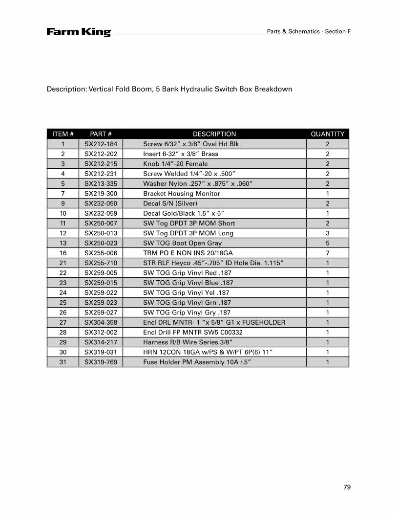
79
ITEM # PART # DESCRIPTION QUANTITY
1 SX212-184 Screw 6/32” x 3/8” Oval Hd Blk 2
2 SX212-202 Insert 6-32” x 3/8” Brass 2
3 SX212-215 Knob 1/4”-20 Female 2
4 SX212-231 Screw Welded 1/4”-20 x .500” 2
5 SX213-335 Washer Nylon .257” x .875” x .060” 2
7 SX219-300 Bracket Housing Monitor 1
9 SX232-050 Decal S/N (Silver) 2
10 SX232-059 Decal Gold/Black 1.5” x 5” 1
11 SX250-007 SW Tog DPDT 3P MOM Short 2
12 SX250-013 SW Tog DPDT 3P MOM Long 3
13 SX250-023 SW TOG Boot Open Gray 5
16 SX255-006 TRM PO E NON INS 20/18GA 7
21 SX255-710 STR RLF Heyco .45”-.705” ID Hole Dia. 1.115” 1
22 SX259-005 SW TOG Grip Vinyl Red .187 1
23 SX259-015 SW TOG Grip Vinyl Blue .187 1
24 SX259-022 SW TOG Grip Vinyl Yel .187 1
25 SX259-023 SW TOG Grip Vinyl Grn .187 1
26 SX259-027 SW TOG Grip Vinyl Gry .187 1
27 SX304-358 Encl DRL MNTR- 1 ”x 5/8” G1 x FUSEHOLDER 1
28 SX312-002 Encl Drill FP MNTR SW5 C00332 1
29 SX314-217 Harness R/B Wire Series 3/8” 1
30 SX319-031 HRN 12CON 18GA w/PS & W/PT 6P(6) 11” 1
31 SX319-769 Fuse Holder PM Assembly 10A /.5” 1
Description: Vertical Fold Boom, 5 Bank Hydraulic Switch Box Breakdown
Parts & Schematics - Section F
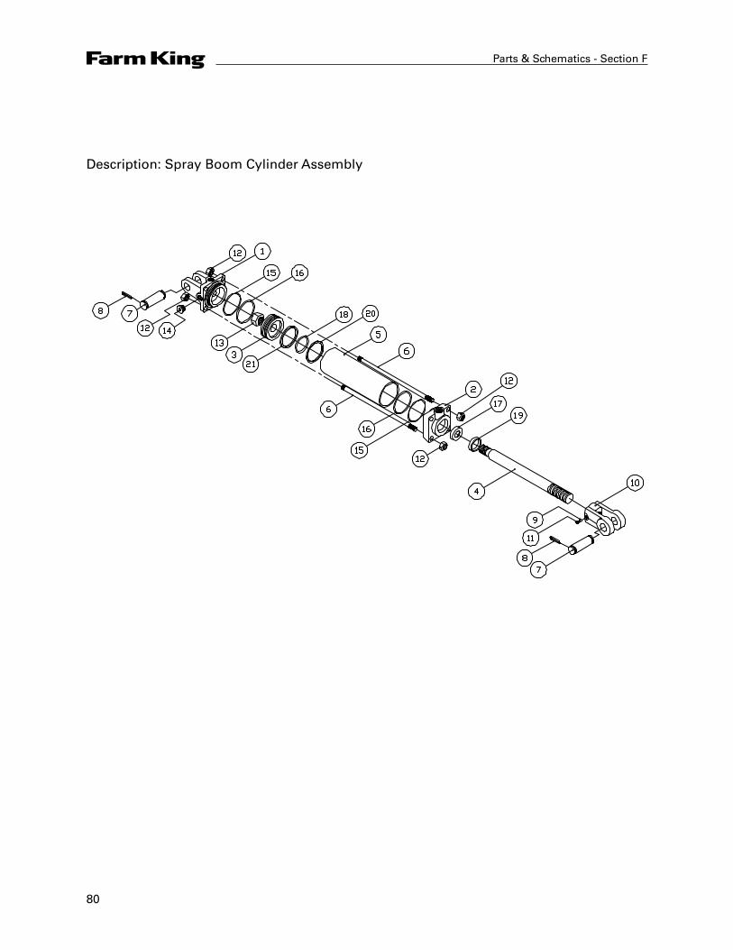
80
Description: Spray Boom Cylinder Assembly
Parts & Schematics - Section F
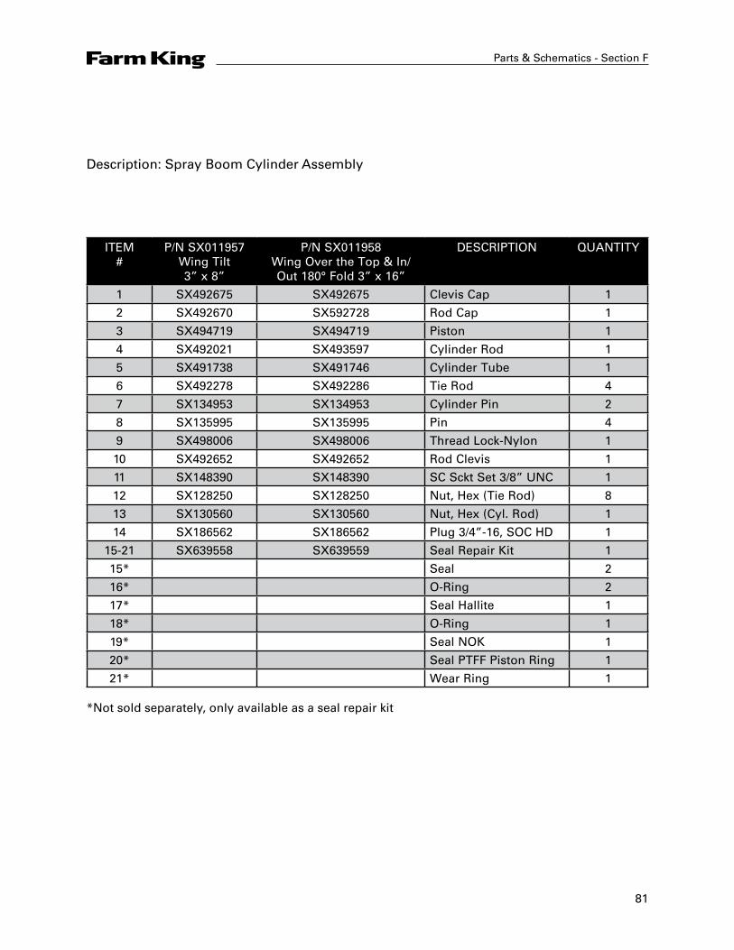
81
ITEM #
P/N SX011957 Wing Tilt 3” x 8”
P/N SX011958 Wing Over the Top & In/Out 180° Fold 3” x 16”
DESCRIPTION QUANTITY
1 SX492675 SX492675 Clevis Cap 1
2 SX492670 SX592728 Rod Cap 1
3 SX494719 SX494719 Piston 1
4 SX492021 SX493597 Cylinder Rod 1
5 SX491738 SX491746 Cylinder Tube 1
6 SX492278 SX492286 Tie Rod 4
7 SX134953 SX134953 Cylinder Pin 2
8 SX135995 SX135995 Pin 4
9 SX498006 SX498006 Thread Lock-Nylon 1
10 SX492652 SX492652 Rod Clevis 1
11 SX148390 SX148390 SC Sckt Set 3/8” UNC 1
12 SX128250 SX128250 Nut, Hex (Tie Rod) 8
13 SX130560 SX130560 Nut, Hex (Cyl. Rod) 1
14 SX186562 SX186562 Plug 3/4”-16, SOC HD 1
15-21 SX639558 SX639559 Seal Repair Kit 1
15* Seal 2
16* O-Ring 2
17* Seal Hallite 1
18* O-Ring 1
19* Seal NOK 1
20* Seal PTFF Piston Ring 1
21* Wear Ring 1
*Not sold separately, only available as a seal repair kit
Description: Spray Boom Cylinder Assembly
Parts & Schematics - Section F
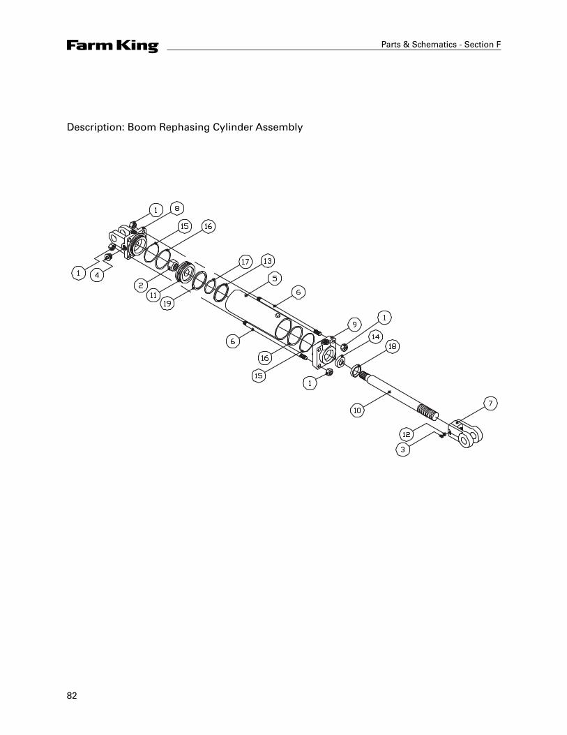
82
Description: Boom Rephasing Cylinder Assembly
Parts & Schematics - Section F
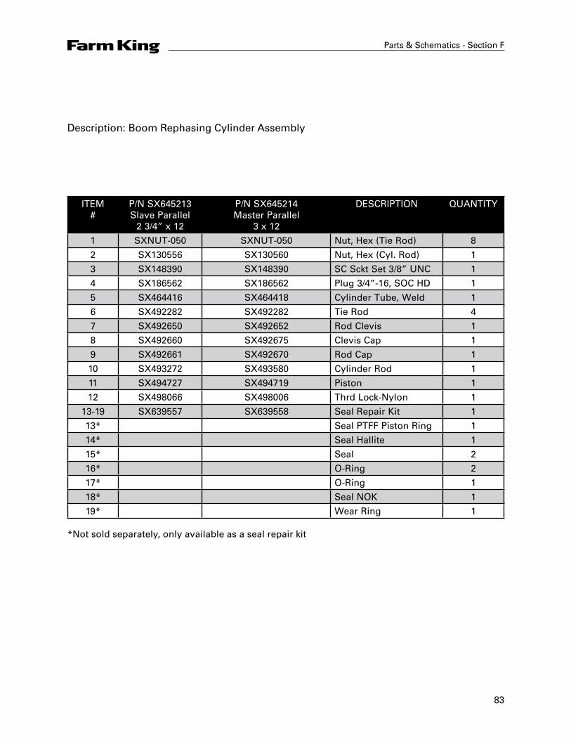
83
ITEM #
P/N SX645213 Slave Parallel
2 3/4” x 12
P/N SX645214 Master Parallel
3 x 12
DESCRIPTION QUANTITY
1 SXNUT-050 SXNUT-050 Nut, Hex (Tie Rod) 8
2 SX130556 SX130560 Nut, Hex (Cyl. Rod) 1
3 SX148390 SX148390 SC Sckt Set 3/8” UNC 1
4 SX186562 SX186562 Plug 3/4”-16, SOC HD 1
5 SX464416 SX464418 Cylinder Tube, Weld 1
6 SX492282 SX492282 Tie Rod 4
7 SX492650 SX492652 Rod Clevis 1
8 SX492660 SX492675 Clevis Cap 1
9 SX492661 SX492670 Rod Cap 1
10 SX493272 SX493580 Cylinder Rod 1
11 SX494727 SX494719 Piston 1
12 SX498066 SX498006 Thrd Lock-Nylon 1
13-19 SX639557 SX639558 Seal Repair Kit 1
13* Seal PTFF Piston Ring 1
14* Seal Hallite 1
15* Seal 2
16* O-Ring 2
17* O-Ring 1
18* Seal NOK 1
19* Wear Ring 1
*Not sold separately, only available as a seal repair kit
Description: Boom Rephasing Cylinder Assembly
Parts & Schematics - Section F
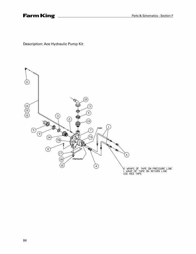
84
Description: Ace Hydraulic Pump Kit
Parts & Schematics - Section F
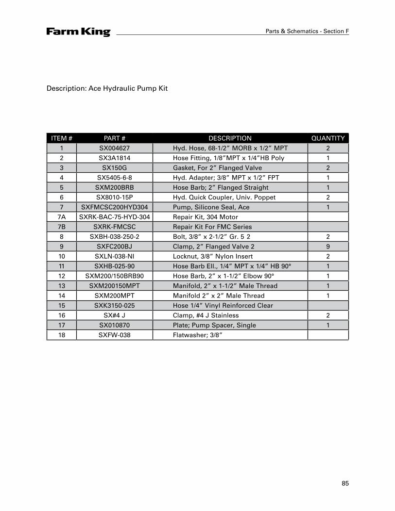
85
Description: Ace Hydraulic Pump Kit
ITEM # PART # DESCRIPTION QUANTITY
1 SX004627 Hyd. Hose, 68-1/2” MORB x 1/2” MPT 2
2 SX3A1814 Hose Fitting, 1/8”MPT x 1/4”HB Poly 1
3 SX150G Gasket, For 2” Flanged Valve 2
4 SX5405-6-8 Hyd. Adapter; 3/8” MPT x 1/2” FPT 1
5 SXM200BRB Hose Barb; 2” Flanged Straight 1
6 SX8010-15P Hyd. Quick Coupler, Univ. Poppet 2
7 SXFMCSC200HYD304 Pump, Silicone Seal, Ace 1
7A SXRK-BAC-75-HYD-304 Repair Kit, 304 Motor
7B SXRK-FMCSC Repair Kit For FMC Series
8 SXBH-038-250-2 Bolt, 3/8” x 2-1/2” Gr. 5 2 2
9 SXFC200BJ Clamp, 2” Flanged Valve 2 9
10 SXLN-038-NI Locknut, 3/8” Nylon Insert 2
11 SXHB-025-90 Hose Barb Ell., 1/4” MPT x 1/4” HB 90° 1
12 SXM200/150BRB90 Hose Barb, 2” x 1-1/2” Elbow 90° 1
13 SXM200150MPT Manifold, 2” x 1-1/2” Male Thread 1
14 SXM200MPT Manifold 2” x 2” Male Thread 1
15 SXK3150-025 Hose 1/4” Vinyl Reinforced Clear
16 SX#4 J Clamp, #4 J Stainless 2
17 SX010870 Plate; Pump Spacer, Single 1
18 SXFW-038 Flatwasher; 3/8”
Parts & Schematics - Section F
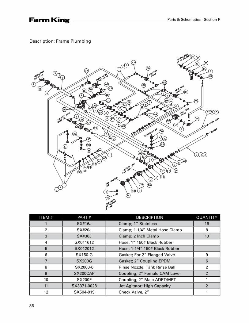
86
ITEM # PART # DESCRIPTION QUANTITY
1 SX#16J Clamp; 1” Stainless 16
2 SX#20J Clamp; 1-1/4” Metal Hose Clamp 8
3 SX#36J Clamp; 2 Inch Clamp 10
4 SX011612 Hose; 1” 150# Black Rubber
5 SX012012 Hose; 1-1/4” 150# Black Rubber
6 SX150-G Gasket; For 2” Flanged Valve 9
7 SX200G Gasket; 2” Coupling EPDM 6
8 SX2000-6 Rinse Nozzle; Tank Rinse Ball 2
9 SX200CAP Coupling; 2” Female CAM Lever 2
10 SX200F Coupling; 2” Male ADPT/MPT 1
11 SX3371-0028 Jet Agitator; High Capacity 2
12 SX504-019 Check Valve, 2” 1
Description: Frame Plumbing
Parts & Schematics - Section F
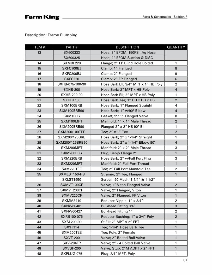
87
ITEM # PART # DESCRIPTION QUANTITY
13 SX600333 Hose, 2” EPDM, 150PSI, Ag Hose
SX600325 Hose; 2” EPDM Suction & DISC
14 SXMBF220 Flange; 2” FP Blind Hole Bolted 1
15 SXFC100BJ Clamp; 1” Flanged 8
16 SXFC200BJ Clamp; 2” Flanged 9
17 SXFC220 Clamp; 2” FP Flanged 6
18 SXHB-075-100-90 Hose Barb Ell; 3/4” MPT x 1” HB Poly 2
19 SXHB-200 Hose Barb; 2” MPT x HB Poly 4
20 SXHB-200-90 Hose Barb Ell; 2” MPT x HB Poly 1
21 SXHBT100 Hose Barb Tee; 1” HB x HB x HB 2
22 SXM100BRB Hose Barb; 1” Flanged Straight 4
23 SXM100BRB90 Hose Barb; 1” w/90° Elbow 4
24 SXM100G Gasket; for 1” Flanged Valve 8
25 SXM100MPT Manifold; 1” x 1” Male Thread 2
26 SXM200BRB90 Flanged 2” x 2” HB 90° Ell 1
27 SXM200/100TEE Tee; 2” x 1” Tee 2
28 SXM200/125BRB Hose Barb; 2” x 1-1/4” Straight 1
29 SXM200/125BRB90 Hose Barb; 2” x 1-1/4” Elbow 90° 4
30 SXM200MPT Manifold; 2” x 2” Male Thread 3
31 SXM200PLG Plug; Banjo Flange 2” 1
32 SXM220BRB Hose Barb; 2” w/Full Port Flng 3
33 SXM220MPT Manifold; 2” Full Port Thread 1
34 SXM220TEE Tee; 2” Full Port Manifold Tee 2
35 SXMLST150-HB Strainer; 2” Tee, Flanged 1
SXLST1550 Screen; 50 Mesh, 1-1/4” & 1-1/2”
36 SXMVT100CF Valve; 1” Viton Flanged Valve 2
37 SXMVT200CF Valve; 2” Flanged, Viton 1
38 SXMV220CF Valve; 2” Flanged, FP Viton 1
39 SXMM3410 Reducer Nipple, 1” x 3/4” 2
40 SXNW60401 Bulkhead Fitting 3/4” 3
41 SXNW60427 Bulkhead Fitting 1” 2
42 SXRB100-075 Reducer Bushing; 1” x 3/4” Poly 2
43 SXSL200-90 St Ell; 2” MPT x 2” FPT 1
44 SX3T114 Tee; 1-1/4” Hose Barb Tee 1
45 SXM200TEE Tee; Poly, 2” Female 1
46 SXVT-200 Valve; 2” Bolted Ball Valve 1
47 SXV-204FP Valve; 2” - 4 Bolted Ball Valve 1
48 SXVSF-200 Valve; Stub, 2”M ADPT x 2” FPT 1
48 SXPLUG 075 Plug; 3/4” MPT, Poly 1
Description: Frame Plumbing
Parts & Schematics - Section F
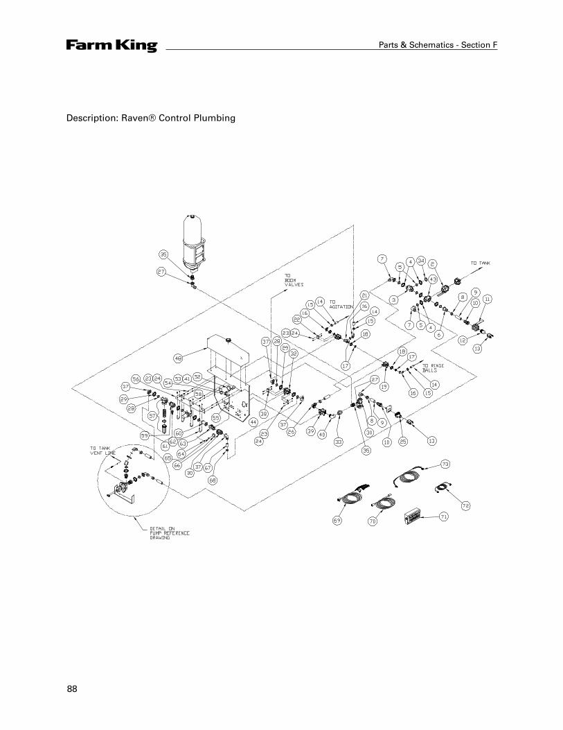
Parts & Schematics - Section F
Description: Raven® Control Plumbing
88
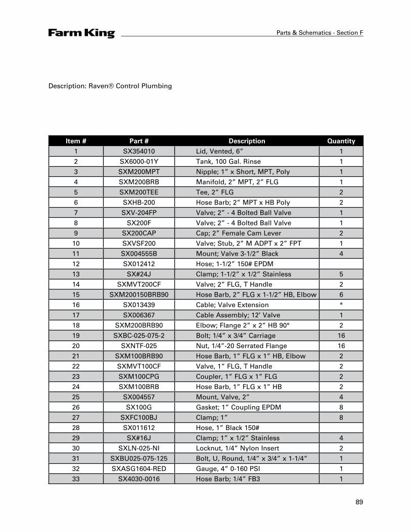
Parts & Schematics - Section F
Description: Raven® Control Plumbing
89
Item # Part # Description Quantity
1 SX354010 Lid, Vented, 6” 1
2 SX6000-01Y Tank, 100 Gal. Rinse 1
3 SXM200MPT Nipple; 1” x Short, MPT, Poly 1
4 SXM200BRB Manifold, 2” MPT, 2” FLG 1
5 SXM200TEE Tee, 2” FLG 2
6 SXHB-200 Hose Barb; 2” MPT x HB Poly 2
7 SXV-204FP Valve; 2” - 4 Bolted Ball Valve 1
8 SX200F Valve; 2” - 4 Bolted Ball Valve 1
9 SX200CAP Cap; 2” Female Cam Lever 2
10 SXVSF200 Valve; Stub, 2” M ADPT x 2” FPT 1
11 SX004555B Mount; Valve 3-1/2” Black 4
12 SX012412 Hose; 1-1/2” 150# EPDM
13 SX#24J Clamp; 1-1/2” x 1/2” Stainless 5
14 SXMVT200CF Valve; 2” FLG, T Handle 2
15 SXM200150BRB90 Hose Barb, 2” FLG x 1-1/2” HB, Elbow 6
16 SX013439 Cable; Valve Extension *
17 SX006367 Cable Assembly; 12’ Valve 1
18 SXM200BRB90 Elbow; Flange 2” x 2” HB 90° 2
19 SXBC-025-075-2 Bolt; 1/4” x 3/4” Carriage 16
20 SXNTF-025 Nut, 1/4”-20 Serrated Flange 16
21 SXM100BRB90 Hose Barb, 1” FLG x 1” HB, Elbow 2
22 SXMVT100CF Valve, 1” FLG, T Handle 2
23 SXM100CPG Coupler, 1” FLG x 1” FLG 2
24 SXM100BRB Hose Barb, 1” FLG x 1” HB 2
25 SX004557 Mount, Valve, 2” 4
26 SX100G Gasket; 1” Coupling EPDM 8
27 SXFC100BJ Clamp; 1” 8
28 SX011612 Hose, 1” Black 150#
29 SX#16J Clamp; 1” x 1/2” Stainless 4
30 SXLN-025-NI Locknut, 1/4” Nylon Insert 2
31 SXBU025-075-125 Bolt, U, Round, 1/4” x 3/4” x 1-1/4” 1
32 SXASG1604-RED Gauge, 4” 0-160 PSI 1
33 SX4030-0016 Hose Barb; 1/4” FB3 1
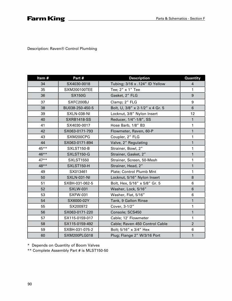
Parts & Schematics - Section F
Description: Raven® Control Plumbing
90
Item # Part # Description Quantity
34 SX4030-0018 Tubing; 3/16 x .124” ID Yellow 4
35 SXM200100TEE Tee; 2” x 1” Tee 1
36 SX150G Gasket, 2” FLG 9
37 SXFC200BJ Clamp; 2” FLG 9
38 BU038-250-450-5 Bolt, U, 3/8” x 2-1/2” x 4 Gr. 5 6
39 SXLN-038-NI Locknut, 3/8” Nylon Insert 12
40 SXRB1418-SS Reducer, 1/4”-1/8”, SS 1
41 SX4030-0017 Hose Barb, 1/8” B3 1
42 SX063-0171-793 Flowmeter, Raven, 60-P 1
43 SXM200CPG Coupler, 2” FLG 1
44 SX063-0171-894 Valve, 2” Regulating 1
45** SXLST150-B Strainer, Bowl, 2” 1
46** SXLST150-G Strainer, Gasket, 2” 1
47** SXLST1550 Strainer, Screen, 50-Mesh 1
48** SXLST150-H Strainer, Head, 2” 1
49 SX013461 Plate; Control Plumb Mnt 1
50 SXLN-031-NI Locknut, 5/16” Nylon Insert 8
51 SXBH-031-062-5 Bolt, Hex, 5/16” x 5/8” Gr. 5 6
52 SXLW-031 Washer, Lock, 5/16” 6
53 SXFW-031 Washer, Flat, 5/16” 6
54 SX6000-02Y Tank, 9 Gallon Rinse 1
55 SX200972 Cover, 3-1/2” 1
56 SX063-0171-220 Console; SCS450 1
57 SX115-0159-017 Cable; 12’ Flowmeter 1
58 SX115-0159-492 Cable; Raven 450 Control Cable 2
59 SXBH-031-075-2 Bolt; 5/16” x 3/4” Hex 6
60 SXM200PLG018 Plug; Flange 2” W/3/16 Port 1
* Depends on Quantity of Boom Valves** Complete Assembly Part # is MLST150-50

Parts & Schematics - Section F
NOTES:
91
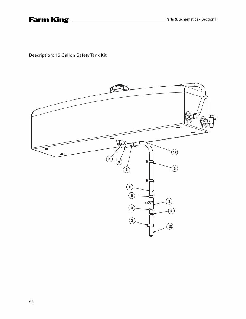
92
Description: 15 Gallon Safety Tank Kit
Parts & Schematics - Section F
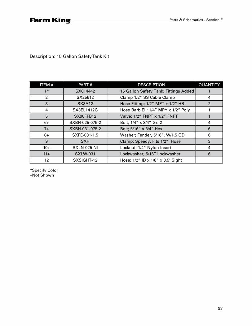
93
Description: 15 Gallon Safety Tank Kit
ITEM # PART # DESCRIPTION QUANTITY
1* SX014442 15 Gallon Safety Tank; Fittings Added 1
2 SX25612 Clamp 1/2” SS Cable Clamp 4
3 SX3A12 Hose Fitting; 1/2” MPT x 1/2” HB 2
4 SX3EL1412G Hose Barb Ell; 1/4” MPY x 1/2” Poly 1
5 SX90FFB12 Valve; 1/2” FNPT x 1/2” FNPT 1
6+ SXBH-025-075-2 Bolt; 1/4” x 3/4” Gr. 2 4
7+ SXBH-031-075-2 Bolt; 5/16” x 3/4” Hex 6
8+ SXFE-031-1.5 Washer; Fender, 5/16”, W/1.5 OD 6
9 SXH Clamp; Speedy, Fits 1/2”’ Hose 3
10+ SXLN-025-NI Locknut; 1/4” Nylon Insert 4
11+ SXLW-031 Lockwasher; 5/16” Lockwasher 6
12 SXSIGHT-12 Hose; 1/2” ID x 1/8” x 3.5’ Sight
*Specify Color+Not Shown
Parts & Schematics - Section F
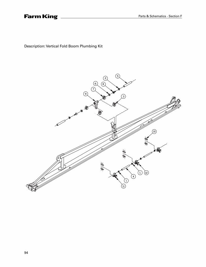
94
Description: Vertical Fold Boom Plumbing Kit
Parts & Schematics - Section F
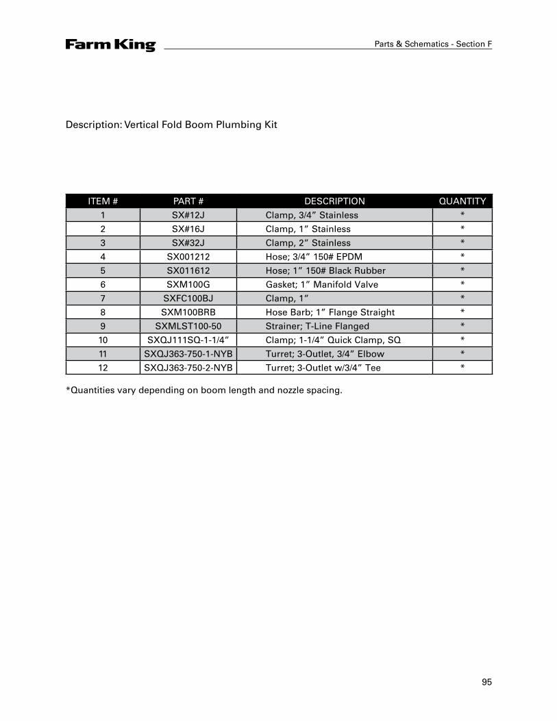
95
Description: Vertical Fold Boom Plumbing Kit
ITEM # PART # DESCRIPTION QUANTITY
1 SX#12J Clamp, 3/4” Stainless *
2 SX#16J Clamp, 1” Stainless *
3 SX#32J Clamp, 2” Stainless *
4 SX001212 Hose; 3/4” 150# EPDM *
5 SX011612 Hose; 1” 150# Black Rubber *
6 SXM100G Gasket; 1” Manifold Valve *
7 SXFC100BJ Clamp, 1” *
8 SXM100BRB Hose Barb; 1” Flange Straight *
9 SXMLST100-50 Strainer; T-Line Flanged *
10 SXQJ111SQ-1-1/4” Clamp; 1-1/4” Quick Clamp, SQ *
11 SXQJ363-750-1-NYB Turret; 3-Outlet, 3/4” Elbow *
12 SXQJ363-750-2-NYB Turret; 3-Outlet w/3/4” Tee *
*Quantities vary depending on boom length and nozzle spacing.
Parts & Schematics - Section F
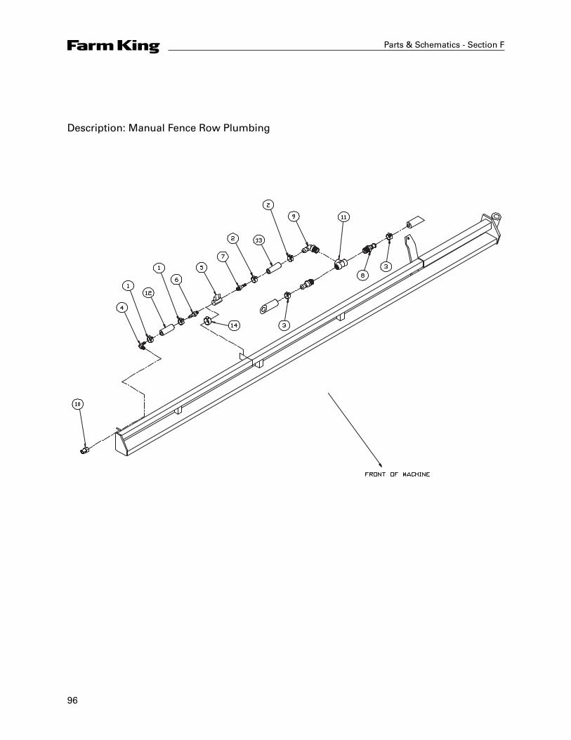
96
Description: Manual Fence Row Plumbing
Parts & Schematics - Section F
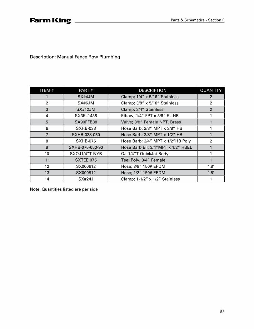
97
Description: Manual Fence Row Plumbing
ITEM # PART # DESCRIPTION QUANTITY
1 SX#4JM Clamp; 1/4” x 5/16” Stainless 2
2 SX#6JM Clamp; 3/8” x 5/16” Stainless 2
3 SX#12JM Clamp; 3/4” Stainless 2
4 SX3EL1438 Elbow; 1/4” FPT x 3/8” EL HB 1
5 SX90FFB38 Valve; 3/8” Female NPT, Brass 1
6 SXHB-038 Hose Barb; 3/8” MPT x 3/8” HB 1
7 SXHB-038-050 Hose Barb; 3/8” MPT x 1/2” HB 1
8 SXHB-075 Hose Barb; 3/4” MPT x 1/2”HB Poly 2
9 SXHB-075-050-90 Hose Barb Ell; 3/4”MPT x 1/2” HBEL 1
10 SXQJ1/4”T-NYB QJ-1/4”T QuickJet Body 1
11 SXTEE 075 Tee: Poly, 3/4” Female 1
12 SX000612 Hose; 3/8” 150# EPDM 1.8'
13 SX000812 Hose; 1/2” 150# EPDM 1.8'
14 SX#24J Clamp; 1-1/2” x 1/2” Stainless 1
Note: Quantities listed are per side
Parts & Schematics - Section F
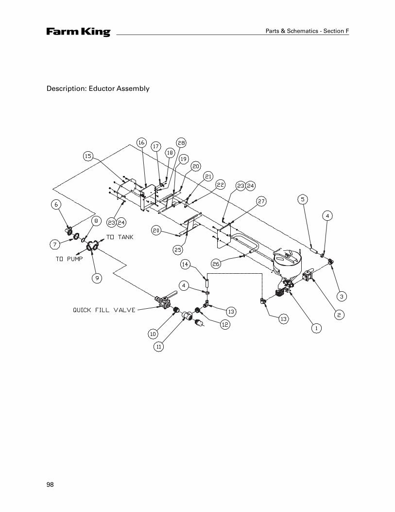
98
Description: Eductor Assembly
Parts & Schematics - Section F
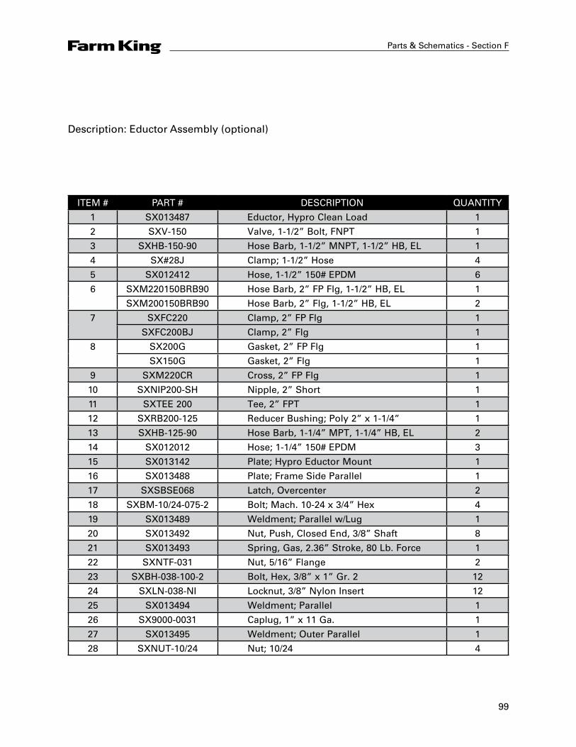
99
ITEM # PART # DESCRIPTION QUANTITY
1 SX013487 Eductor, Hypro Clean Load 1
2 SXV-150 Valve, 1-1/2” Bolt, FNPT 1
3 SXHB-150-90 Hose Barb, 1-1/2” MNPT, 1-1/2” HB, EL 1
4 SX#28J Clamp; 1-1/2” Hose 4
5 SX012412 Hose, 1-1/2” 150# EPDM 6
6 SXM220150BRB90 Hose Barb, 2” FP Flg, 1-1/2” HB, EL 1
SXM200150BRB90 Hose Barb, 2” Flg, 1-1/2” HB, EL 2
7 SXFC220 Clamp, 2” FP Flg 1
SXFC200BJ Clamp, 2” Flg 1
8 SX200G Gasket, 2” FP Flg 1
SX150G Gasket, 2” Flg 1
9 SXM220CR Cross, 2” FP Flg 1
10 SXNIP200-SH Nipple, 2” Short 1
11 SXTEE 200 Tee, 2” FPT 1
12 SXRB200-125 Reducer Bushing; Poly 2” x 1-1/4” 1
13 SXHB-125-90 Hose Barb, 1-1/4” MPT, 1-1/4” HB, EL 2
14 SX012012 Hose; 1-1/4” 150# EPDM 3
15 SX013142 Plate; Hypro Eductor Mount 1
16 SX013488 Plate; Frame Side Parallel 1
17 SXSBSE068 Latch, Overcenter 2
18 SXBM-10/24-075-2 Bolt; Mach. 10-24 x 3/4” Hex 4
19 SX013489 Weldment; Parallel w/Lug 1
20 SX013492 Nut, Push, Closed End, 3/8” Shaft 8
21 SX013493 Spring, Gas, 2.36” Stroke, 80 Lb. Force 1
22 SXNTF-031 Nut, 5/16” Flange 2
23 SXBH-038-100-2 Bolt, Hex, 3/8” x 1” Gr. 2 12
24 SXLN-038-NI Locknut, 3/8” Nylon Insert 12
25 SX013494 Weldment; Parallel 1
26 SX9000-0031 Caplug, 1” x 11 Ga. 1
27 SX013495 Weldment; Outer Parallel 1
28 SXNUT-10/24 Nut; 10/24 4
Description: Eductor Assembly (optional)
Parts & Schematics - Section F
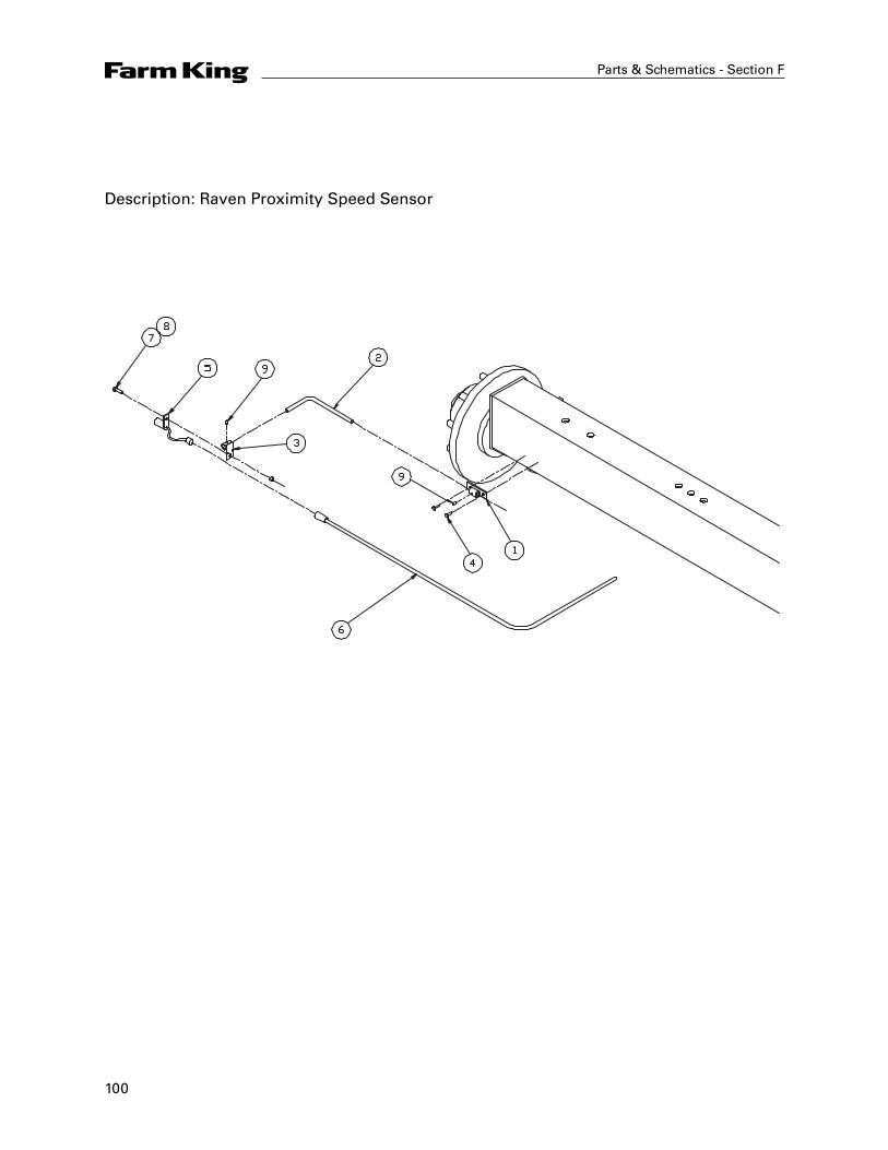
100
Description: Raven Proximity Speed Sensor
Parts & Schematics - Section F
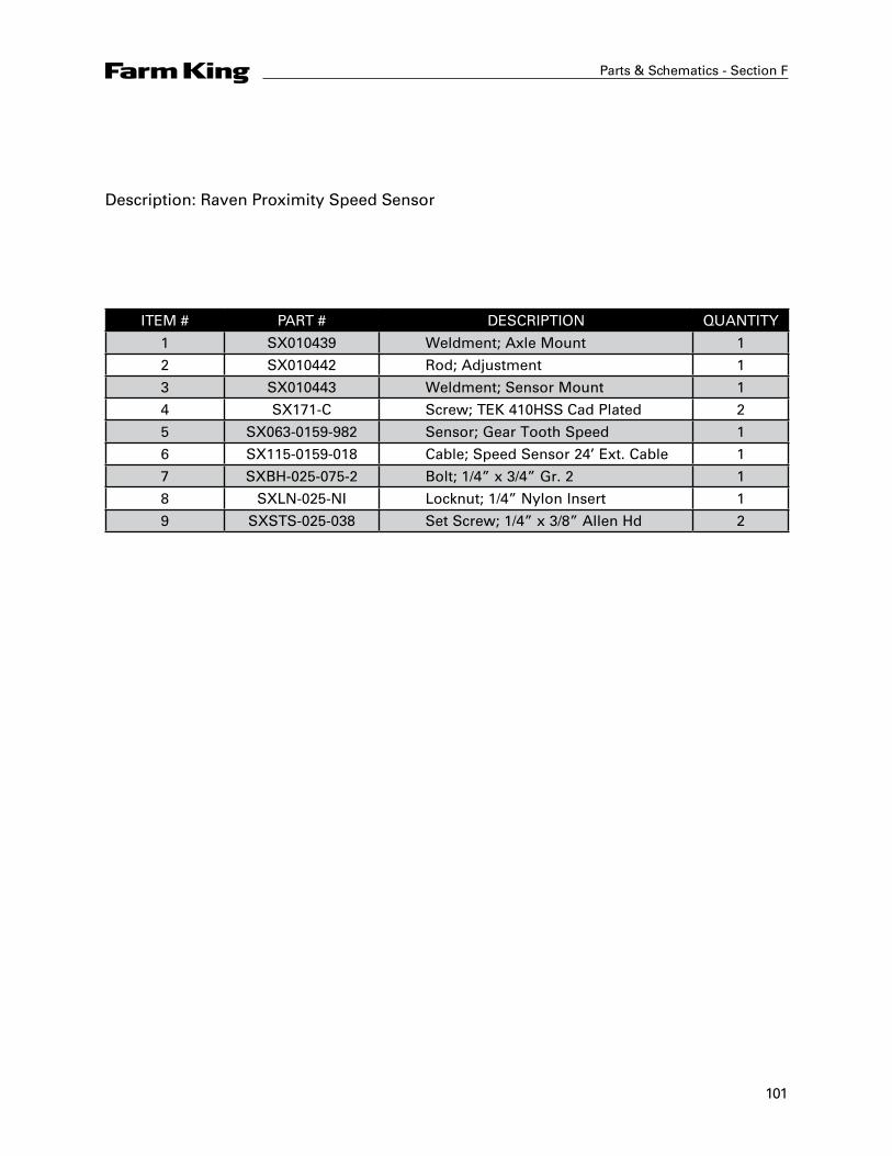
101
Description: Raven Proximity Speed Sensor
ITEM # PART # DESCRIPTION QUANTITY
1 SX010439 Weldment; Axle Mount 1
2 SX010442 Rod; Adjustment 1
3 SX010443 Weldment; Sensor Mount 1
4 SX171-C Screw; TEK 410HSS Cad Plated 2
5 SX063-0159-982 Sensor; Gear Tooth Speed 1
6 SX115-0159-018 Cable; Speed Sensor 24’ Ext. Cable 1
7 SXBH-025-075-2 Bolt; 1/4” x 3/4” Gr. 2 1
8 SXLN-025-NI Locknut; 1/4” Nylon Insert 1
9 SXSTS-025-038 Set Screw; 1/4” x 3/8” Allen Hd 2
Parts & Schematics - Section F
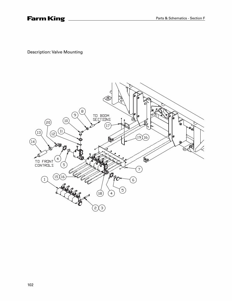
102
Description: Valve Mounting
Parts & Schematics - Section F
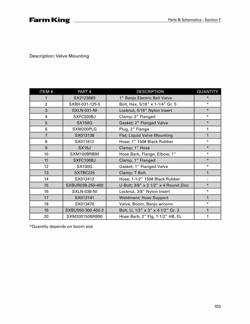
103
Description: Valve Mounting
ITEM # PART # DESCRIPTION QUANTITY
1 SX2123683 1” Banjo Electric Ball Valve *
2 SXBH-031-125-5 Bolt, Hex, 5/16” x 1-1/4” Gr. 5 *
3 SXLN-031-NI Locknut, 5/16” Nylon Insert *
4 SXFC200BJ Clamp; 2” Flanged *
5 SX150G Gasket; 2” Flanged Valve *
6 SXM200PLG Plug, 2” Flange 1
7 SX013138 Flat; Liquid Valve Mounting 1
8 SX011612 Hose; 1” 150# Black Rubber *
9 SX16J Clamp; 1” Hose *
10 SXM100BRB90 Hose Barb, Flange, Elbow, 1” *
11 SXFC100BJ Clamp, 1” Flanged *
12 SX100G Gasket; 1” Flanged Valve *
13 SXTBC225 Clamp; T-Bolt 1
14 SX012412 Hose; 1-1/2” 150# Black Rubber -
15 SXBUR038-250-400 U-Bolt; 3/8” x 2 1/2” x 4 Round Zinc *
16 SXLN-038-NI Locknut, 3/8” Nylon Insert *
17 SX013141 Weldment; Hose Support 1
18 SX013470 Valve, Boom, Banjo w/conn. *
19 SXBU050-300-450-2 Bolt, U, 1/2” x 3” x 4-1/2” Gr. 2 1
20 SXM200150BRB90 Hose Barb, 2” Flg, 1-1/2” HB, EL 1
*Quantity depends on boom size
Parts & Schematics - Section F

104
NOTES
Parts & Schematics - Section F

Warranty Section G
105105
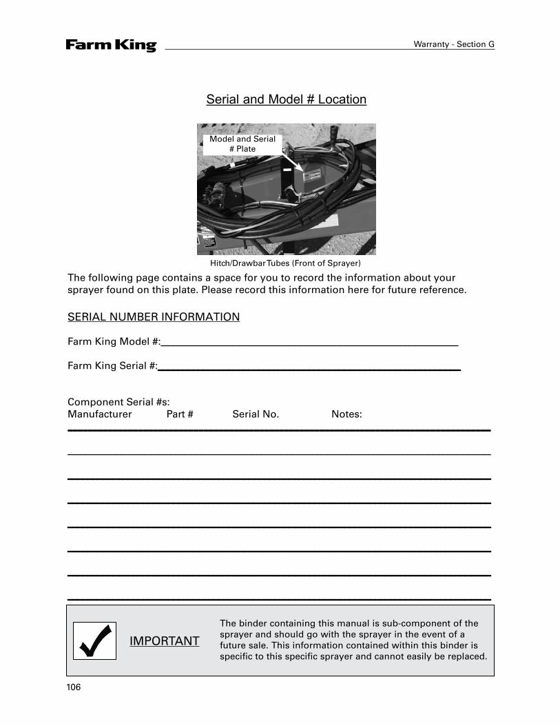
106
The following page contains a space for you to record the information about your sprayer found on this plate. Please record this information here for future reference.
SERIAL NUMBER INFORMATION
Farm King Model #:___________________________________________________________
Farm King Serial #:____________________________________________________________
Component Serial #s:Manufacturer Part # Serial No. Notes:____________________________________________________________________________________
____________________________________________________________________________________
____________________________________________________________________________________
____________________________________________________________________________________
____________________________________________________________________________________
____________________________________________________________________________________
____________________________________________________________________________________
____________________________________________________________________________________
Serial and Model # Location
IMPORTANT
The binder containing this manual is sub-component of the sprayer and should go with the sprayer in the event of a future sale. This information contained within this binder is specific to this specific sprayer and cannot easily be replaced.
Hitch/Drawbar Tubes (Front of Sprayer)
Model and Serial # Plate
Warranty - Section G
107
Farm King Pull-Type Sprayer Limited WarrantyThis document limits your warranty rights.
Base Limited WarrantyFarm King provides this warranty only to original retail purchasers of its sprayers. Farm King warrants to such purchasers that all Farm King-manufactured parts and components used and serviced as provided for in the Operator’s Manual shall be free from defects in materials and workmanship for a period following delivery to the original retail purchaser of one (1) year. This limited warranty applies only to those parts and components manufactured by Farm King. Parts and components manufactured by others are subject to their manufacturer’s warranties, if any.
Farm King will fulfill this limited warranty by, at its option, repairing or replacing any covered part that is defective or is the result of improper workmanship, provided that the part is returned to Farm King within thirty (30) days of the date that such defect or improper workmanship is, or should have been, discovered. Parts must be returned through the selling representative and the buyer must prepay transportation charges.
Farm King will not be responsible for repairs or replacements that are necessitated, in whole or part, by the use of parts not manufactured by or obtained from Farm King. Under no circumstances are component parts warranted against normal wear and tear. There is no warranty on product pump seals, product pump bearings, rubber product hoses, pressure gauges, or other components that require replacement as part of normal maintenance.
Repair Parts Limited WarrantyFarm King warrants genuine Farm King replacement parts purchased after the expiration of the Farm King Limited Warranty, and used and serviced as provided for in the Operator’s Manual, to be free from defects in materials or workmanship for a period of thirty (30) days from the invoice date for the parts. Farm King will fulfill this limited warranty by, at its option, repairing or replacing any covered part that is defective or is the result of improper workmanship, provided that the part is returned to Farm King within thirty (30) days of the date that such defect or improper workmanship is, or should have been, discovered. Such parts must be shipped to the Farm King factory at the purchaser’s expense.
What is Not CoveredUnder no circumstances does this limited warranty cover any components or parts that have been subject to the following: negligence; alteration or modification not approved by Farm King; misuse; improper storage; lack of reasonable and proper maintenance, service, or repair; normal wear; damage from failure to follow operating instructions; accident; and/or repairs that have been made with parts other than those manufactured, supplied, and or authorized by Farm King.
Continued on next page
Warranty Policy
Warranty - Section G
108
Authorized Dealer and Labor CostsRepairs eligible for labor under this limited warranty must be made by Farm King or an authorized Farm King dealer. Farm King retains the exclusive discretion to determine whether it will pay labor costs for warranty repairs or replacements, and the amount of such costs that it will pay and the time in which the repairs will be made. If Farm King determines that it will pay labor costs for warranty work, it will do so by issuing a credit to the dealer’s or distributor’s account. Farm King will not approve or pay invoices sent for repairs that Farm King has not previously approved. Warranty service does not extend the original term of this limited warranty.
Warranty RequirementsTo be covered by warranty, each new sprayer must be registered with Farm King within thirty (30) days of delivery to original retail purchaser. If the customer decides to purchase replacement components before the warranty disposition of such components is determined, Farm King will bill the customer for such components and then credit the replacement invoice for those components later determined to be covered by this limited warranty. Any such replacement components that are determined not be covered by this limited warranty will be subject to the terms of the invoice and shall be paid for by the purchaser.
Exclusive Effect of Warranty and Limitation of Liability
TO THE EXTENT PERMITTED BY LAW, FARM KING DISCLAIMS ANY WARRANTIES, REPRESENTATIONS, OR PROMISES, EXPRESS OR IMPLIED, AS TO THE QUALITY, PERFORMANCE, OR FREEDOM FROM DEFECT OF THE COMPONENTS AND PARTS COVERED BY THIS WARRANTY AND NOT SPECIFICALLY PROVIDED FOR HEREIN.
TO THE EXTENT PERMITTED BY LAW, FARM KING DISCLAIMS ANY IMPLIED WARRANTIES OF MERCHANTABILITY AND FITNESS FOR A PARTICULAR PURPOSE ON ITS PRODUCTS COVERED HEREIN, AND DISCLAIMS ANY RELIANCE BY THE PURCHASER ON FARM KING’S SKILLOR JUDGMENT TO SELECT OR FURNISH GOODS FOR ANY PARTICULAR PURPOSE. THE PURCHASER’S ONLY AND EXCLUSIVE REMEDIES IN CONNECTION WITH THE BREACH OR PERFORMANCE OF ANY WARRANTY ON FARM KING’S SPRAYERS ARE THOSE SET FORTH HEREIN. IN NO EVENT SHALL FARM KING BE LIABLE FOR INCIDENTAL OR CONSEQUENTIAL DAMAGES (INCLUDING, BY WAY OF EXAMPLE ONLY AND NOT LIMITATION, LOSS OF CROPS, LOSS OF PROFITS OR REVENUE, OTHER COMMERCIAL LOSSES, INCOVENIENCE, OR COST OF REPLACEMENT OF RENTAL EQUIPMENT). IN NO EVENT SHALL FARM KING’S CONTRACT OR WARRANTY LIABILITY EXCEED THE PURCHASE PRICE OF THE PRODUCT. (Note that some states do not allow limitations on how long an implied warranty lasts or the exclusion or limitation of incidental or consequential damages, so the above limitations and exclusion may not apply to you.) This warranty gives you specific legal rights and you may also have other rights, which vary from state to sate.
Farm King neither assumes nor authorizes any person or entity, including its selling representatives, to assume any other obligations or liability in connections with the sale of covered equipment, or to make any other warranties, representations, or promises, express or implied, as to the quality, performance, or freedom from defect of the components and parts covered herein. No one is authorized to alter, modify, or enlarge this limited warranty, or its exclusions, limitations and reservations.
Continued on next page.
Warranty - Section G
109
Corrections of defects and improper workmanship in the manner, and for the applicable time periods, provided for herein shall constitute fulfillment of all responsibilities of Farm King to the purchaser, and Farm King shall not be liable in negligence, contract, or on any other basis with respect to the subject equipment.
This limited warranty is subject to any existing conditions of supply which may directly affect Farm King’s ability to obtain materials or manufacturer replacement parts.
Buhler Industries Inc. reserves the right to make improvements in design or changes in specifications to its products at anytime, without incurring any obligation to owners of units previously sold.
Warranty - Section G

www.farm-king.com
a division of Buhler Industries Inc.
1330 43rd Street NWFargo, ND USA 58102Ph.: 701.282.7014 | Fax: 701.282.5865E-mail: [email protected]
Equipment shown is subject to change without notice. ©2010 Buhler Trading Inc. Printed in U.S.A.. TSX:BUI