Embed Size (px)
Citation preview
© 2018 Hoffman Enclosures Inc. PH 763 422 2211 • nVent.com/HOFFMAN 87569298Rev. E P/N 87416628
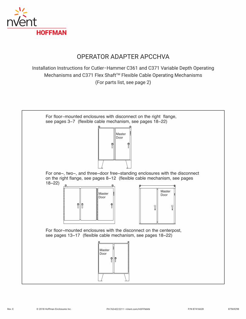
For floor−mounted enclosures with disconnect on the right flange,see pages 3−7 (flexible cable mechanism, see pages 18−22)
For one−, two−, and three−door free−standing enclosures with the disconnecton the right flange, see pages 8−12 (flexible cable mechanism, see pages18−22)
For floor−mounted enclosures with the disconnect on the centerpost,see pages 13−17 (flexible cable mechanism, see pages 18−22)
MasterDoor
MasterDoor
MasterDoor
MasterDoor
OPERATOR ADAPTER APCCHVA
Installation Instructions for Cutler−Hammer C361 and C371 Variable Depth OperatingMechanisms and C371 Flex ShaftTM Flexible Cable Operating Mechanisms
(For parts list, see page 2)

© 2018 Hoffman Enclosures Inc. PH 763 422 2211 • nVent.com/HOFFMAN 87569298- 2 -
WARNINGThe functions, fits, and clearances of the installation described hereon are calculated from information supplied by the
manufactures of the equipment to be installed. Be certain to check the function, fits, and clearances of all equipment both before and after installation to assure that is operates properly and safely and meets all applicable codes, standards, and regulations.
In the event the completed installation does not function properly or fails to meet any such codes, standards, or regulations, do not attempt to make alterations or operate the equipment. Report such facts immediately to:
Hoffman Customer Service2100 Hoffman WayAnoka, MN 55303
763 422 2211http://hoffman.nvent.com/contact-us
PARTS LISTOperator Adapter, Catalog Number APCCHVA for Cutler−Hammer C361, C371 Disconnects
Item No. . . . . . Part Name . . . . . . . . . . . . . . . . . . . . . . . . . . . . . . . . Part No. . . . . . . . . Quantity
1 . . . . . . . . . . . . Mounting Plate for C−H C361, C371 . . . . . . . . . . 87400022 . . . . . . . 1
2 . . . . . . . . . . . . Slide Arm . . . . . . . . . . . . . . . . . . . . . . . . . . . . . . . . . 26250001 . . . . . . . 1
3 . . . . . . . . . . . . Shoulder Collar . . . . . . . . . . . . . . . . . . . . . . . . . . . . 26149001 . . . . . . . 1
4 . . . . . . . . . . . . Screw, 1/4−20x7/8 Hex HD . . . . . . . . . . . . . . . . . . 99401030 . . . . . . . 1
5 . . . . . . . . . . . . Lockwasher, 1/4 Spring . . . . . . . . . . . . . . . . . . . . . 99401318 . . . . . . . 1
6 . . . . . . . . . . . . Washer, Flat . . . . . . . . . . . . . . . . . . . . . . . . . . . . . . 22101003 . . . . . . . 2
7 . . . . . . . . . . . . Lockwasher, 1/4 Int. . . . . . . . . . . . . . . . . . . . . . . . . 99401300 . . . . . . . 2
8 . . . . . . . . . . . . Nut, 1/4−20 Hex . . . . . . . . . . . . . . . . . . . . . . . . . . . 99401406 . . . . . . . 2
9 . . . . . . . . . . . . Door Catch . . . . . . . . . . . . . . . . . . . . . . . . . . . . . . . . 23101002 . . . . . . . 1
10 . . . . . . . . . . . Screw, 10−32x3/8 Pan HD . . . . . . . . . . . . . . . . . . 99401007 . . . . . . . 2
11 . . . . . . . . . . . Lockwasher, #10 Int. . . . . . . . . . . . . . . . . . . . . . . . 99401307 . . . . . . . 2
12 . . . . . . . . . . . Label, (extra) . . . . . . . . . . . . . . . . . . . . . . . . . . . . . . 26147001 . . . . . . . 1
13 . . . . . . . . . . . Installation Instruction . . . . . . . . . . . . . . . . . . . . . . 87416628 . . . . . . . 1

© 2018 Hoffman Enclosures Inc. PH 763 422 2211 • nVent.com/HOFFMAN87569298 - 3 -
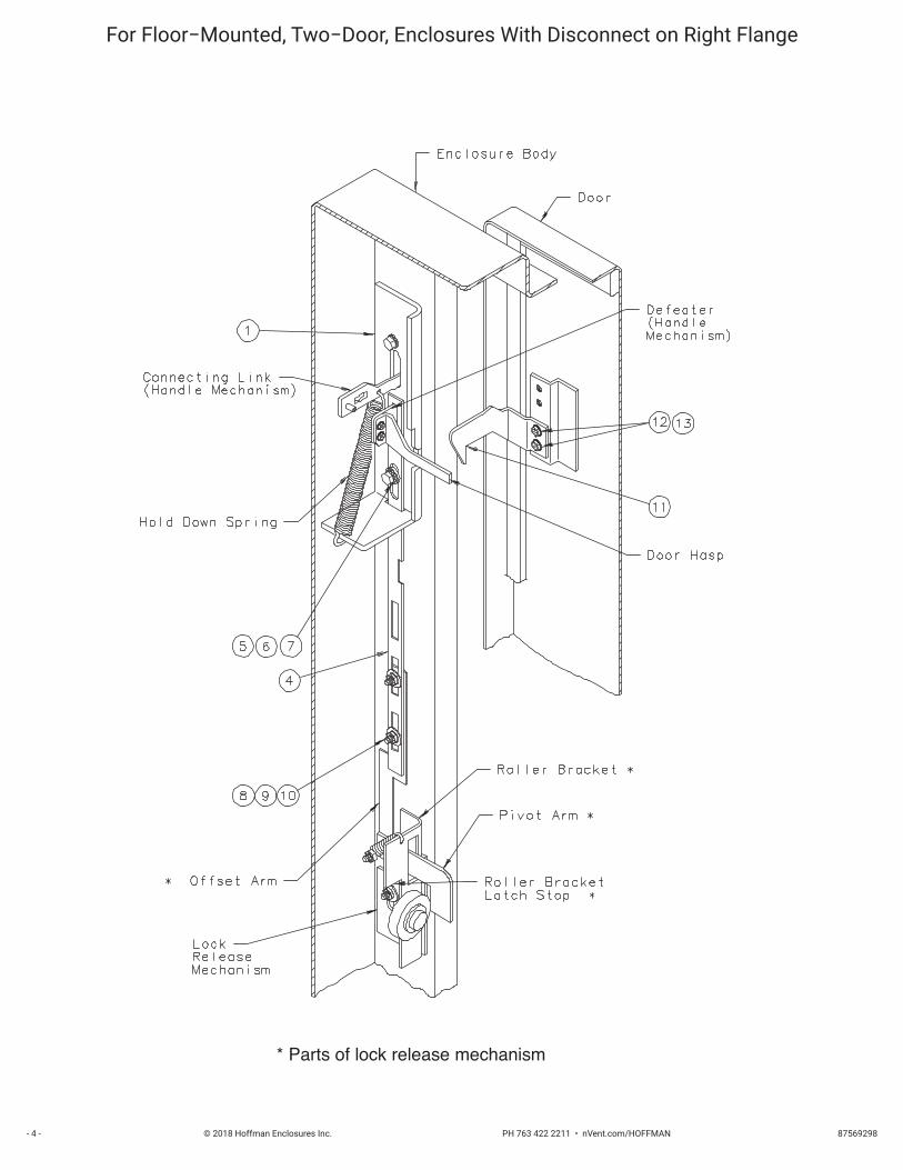
INTRODUCTIONThis installation instruction is for Cutler−Hammer C361, C371 (variable depth) mechanisms. These mechanisms are for disconnect switches and circuit breakers mounted in Hoffman two−door, floor−mounted, enclosures with the disconnect on the right flange.
INSTALLATION STEPSStep 1 − Position mounting plate (item1) on the inside of the enclosure, behind the opening provided.
Step 2 − Discard the Cutler−Hammer spring bracket which is normally installed inside the enclosure flange, behind the C−H handle mechanism.
Step 3 − Assemble the Cutler−Hammer handle mechanism through the opening in the enclosure and through the mounting plate. Omit cap screw and lockwasher which fits into bottom hole of the handle mechanism.
Step 4 − Install the slide arm (item 2) through the slot in the bottom of mounting plate (item 1) and over the defeater part of the handle assembly (on C−H handle mechanism). Place the smaller diameter end of the shoulder collar (item 3) through the oval slot in the slide arm. Install long cap screw (item 4) with lockwasher (item 5) through shoulder collar into the bottom mounting hole of the C−H handle mechanism and tighten. The slide arm and defeater should move up and down smoothly. Install door hasp (C−H part) per Cutler−Hammer instructions.
Step 5 − Attach the bottom of the slide arm (item 2) to the offset arm of the lock release mechanism. Use two flat washers (item 6), two lockwashers (item 7), and two hex nuts (item 8). Do not tighten until parts are adjusted. (see Step 6 − (B) )
Step 6 − The handle safety lock release mechanism is adjustable in two places.
(A) Check the adjustment of the factory installed roller bracket. The door latch should hit against the latch stop portion of the roller bracket when the door is closed and latched. Adjust up or down if necessary. The attached mechanism will then provide the necessary up−down motion required to operate the release mechanism in the C−H handle mechanism.
(B) Adjust the length of the slide arm assembly. With proper adjustment of the slide arm, the safety lock (on Cutler−Hammer handle mechanism) should release just before the master door is fully latched. Lengthen slide arm if safety lock releases too soon. Shorten slide arm if safety lock releases too late.
Step 7 − Attach the door catch (item 9), provided by Hoffman, to the tapped spacer on the door using the bottom set of mounting holes. Use two screws (item 10) and lockwashers (item 11). The door catch prevents the door from being opened when the handle mechanism is in the “ON” position. The door catch may be easily bent up or down to hook properly on the door hasp of the Cutler−Hammer handle mechanism.
Step 8 − Drill and tap holes in panel as shown in diagram and table 1. See Cutler−Hammer instructions for locating extra holes for fuse clips.
Step 9 − Mount switch or circuit breaker using Cutler−Hammer instructions and parts. C−H connecting rod must be cut off per Cutler−Hammer instructions. See table 2 for depth dimensions used to determine length of rod.
MasterDoor
© 2018 Hoffman Enclosures Inc. PH 763 422 2211 • nVent.com/HOFFMAN 87569298- 4 -
For Floor−Mounted, Two−Door, Enclosures With Disconnect on Right Flange
* Parts of lock release mechanism

© 2018 Hoffman Enclosures Inc. PH 763 422 2211 • nVent.com/HOFFMAN87569298 - 5 -
For Floor−Mounted, Two−Door, Enclosures With Disconnect on Right Flange
Hole Pattern For Disconnect Switch SizeC361NC/C361SC 30 AMPC361ND/C361SD 60 AMPC361NE/C361SE 100 AMPC361NF/C361SF 200 AMP

© 2018 Hoffman Enclosures Inc. PH 763 422 2211 • nVent.com/HOFFMAN 87569298- 6 -
For Floor−Mounted, Two−Door, Enclosures With Disconnect on Right Flange
Hole Pattern For Circuit Breaker Frame SizeHMCP, FS, FH, EHD FDB, FD, HFD 150 AMP
HMCP, JS, JH, JL, JD, JDB, HJD, JDC 250 AMPHMCP, HK, KS, KD, DK, KDB, HKD 400 AMP
LH, LS, LC 600 AMP
© 2018 Hoffman Enclosures Inc. PH 763 422 2211 • nVent.com/HOFFMAN87569298 - 7 -
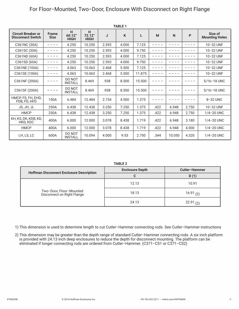
For Floor−Mounted, Two−Door, Enclosure With Disconnect on Right Flange
TABLE 1
Circuit Breaker orDisconnect Switch
FrameSize
H60.12”HIGH
H72.12”HIGH
J K L M N P Size ofMounting Holes
C361NC (30A) − − − − 4.250 10.250 2.593 4.000 7.125 − − − − − − − − − − − − 10−32 UNFC361SC (30A) − − − − 4.250 10.250 2.593 4.000 9.750 − − − − − − − − − − − − 10−32 UNFC361ND (60A) − − − − 4.250 10.250 2.593 4.000 7.125 − − − − − − − − − − − − 10−32 UNFC361SD (60A) − − − − 4.250 10.250 2.593 4.000 9.750 − − − − − − − − − − − − 10−32 UNF
C361NE (100A) − − − − 4.063 10.063 2.468 5.500 7.125 − − − − − − − − − − − − 10−32 UNFC361SE (100A) − − − − 4.063 10.063 2.468 5.500 11.875 − − − − − − − − − − − − 10−32 UNF
C361NF (200A) − − − − DO NOTINSTALL 8.469 .938 8.500 15.500 − − − − − − − − − − − − 5/16−18 UNC
C361SF (200A) − − − − DO NOTINSTALL 8.469 .938 8.500 15.500 − − − − − − − − − − − − 5/16−18 UNC
HMCP, FS, FH, EHD,FDB, FD, HFD 150A 6.484 12.484 2.734 4.500 1.375 − − − − − − − − − − − − 8−32 UNC
JS, JH, JL 250A 6.438 12.438 3.250 7.250 1.375 .422 6.948 2.750 10−32 UNFHMCP 250A 6.438 12.438 3.250 7.250 1.375 .422 6.948 2.750 1/4−20 UNC
KH, KS, DK, KDB, KD,HKD, KDC 400A 6.000 12.000 3.078 8.438 1.719 .422 6.948 3.180 1/4−20 UNC
HMCP 400A 6.000 12.000 3.078 8.438 1.719 .422 6.948 4.000 1/4−20 UNC
LH, LS, LC 600A DO NOTINSTALL 10.094 4.000 9.53 2.750 .344 10.050 4.320 1/4−20 UNC
TABLE 2
Hoffman Disconnect Enclosure DescriptionEnclosure Depth Cutler−Hammer
C D (1)
Two−Door, Floor−MountedDisconnect on Right Flange
12.13 10.91
18.13 16.91 (2)
24.13 22.91 (2)
1) This dimension is used to determine length to cut Cutler−Hammer connecting rods. See Cutler−Hammer instructions
2) This dimension may be greater than the depth range of standard Cutler−Hammer connecting rods. A six inch platform is provided with 24.13 inch deep enclosures to reduce the depth for disconnect mounting. The platform can be eliminated if longer connecting rods are ordered from Cutler−Hammer. (C371−CS1 or C371−CS2)
© 2018 Hoffman Enclosures Inc. PH 763 422 2211 • nVent.com/HOFFMAN 87569298- 8 -
MasterDoorINTRODUCTION
This installation instruction is for Cutler−Hammer C361, C371 (variable depth) mechanisms. These mechanisms are for disconnect switches and circuit breakers mounted in Hoffman one−, two−, and three−door, free−standing, enclosures with the disconnect on the right flange.
INSTALLATION STEPSStep 1 − Position Mounting plate (item 1) on the inside of the enclosure, behind the opening provided.
Step 2 − Discard the Cutler−Hammer spring bracket which is normally installed inside the enclosure flange behind the C−H handle mechanism.
Step 3 − Assemble the Cutler−Hammer handle mechanism through the opening in the enclosure and through the mounting plate. Omit cap screw and lockwasher which fits into bottom hole of the handle mechanism.
Step 4 − Install the slide arm (item 2) through the slot in the bottom of the mounting plate (item 1) and over the defeater part of the handle assembly (on C−H handle mechanism). Place the smaller diameter end of the shoulder collar (item 3) through the oval slot in the slide arm. Install long cap screw (item 4) with lockwasher (item 5) through shoulder collar into the bottom mounting hole of the C−H handle mechanism and tighten. The slide arm and defeater should move up and down smoothly. Install door hasp (C−H part) per Cutler−Hammer instructions.
Step 5 − Attach the bottom of the slide arm (item 2) to the offset arm of the lock release mechanism. Use two flat washers (item 6), two lockwashers (item 7), and two hex nuts (item 8). Do not tighten until parts are adjusted. (see Step 6 − (B) ) )
Step 6 − The handle safety lock release mechanism is adjustable in two places.
(A) Check the adjustment of the factory installed roller bracket. The door latch should hit against the latch stop portion of the roller bracket when the door is closed and latched. Adjust up or down if necessary. The attached mechanism will then provide the necessary up−down motion required to operate the release mechanism in the C−H handle mechanism.
(B) Adjust the length of the slide arm assembly. With proper adjustment of the slide arm, the safety lock (on Cutler−Hammer handle mechanism) should release just before the master door is fully latched. Lengthen slide arm if safety lock releases too soon. Shorten slide arm if safety lock releases too late.
Step 7 − Attach the door catch (item 9), provided by Hoffman, to the tapped spacer on the door using the bottom set of mounting holes. Use two screws (item 10) and lockwashers (item 11). The door catch prevents the door from being opened when the handle mechanism is in the “ON” position. The door catch may be easily bent up or down to hook properly on the door hasp of the Cutler−Hammer handle mechanism.
Step 8 − Drill and tap holes in panel as shown in diagram and table. See Cutler−Hammer instructions for locating extra holes for fuse clips.
Step 9 − Mount switch or circuit breaker using Cutler−Hammer instructions and parts. Cutler−Hammer connecting rod assembly must be cut off per Cutler−Hammer instructions. See table 2 for depth dimensions used to determine length of rod.

© 2018 Hoffman Enclosures Inc. PH 763 422 2211 • nVent.com/HOFFMAN87569298 - 9 -
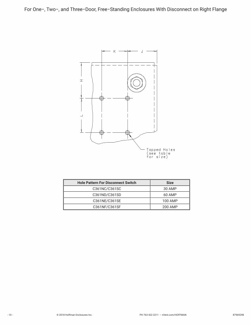
For One−, Two−, and Three−Door, Free−Standing Enclosures With Disconnect on Right Flange
* Parts of lock release mechanism
© 2018 Hoffman Enclosures Inc. PH 763 422 2211 • nVent.com/HOFFMAN 87569298- 10 -
For One−, Two−, and Three−Door, Free−Standing Enclosures With Disconnect on Right Flange
Hole Pattern For Disconnect Switch SizeC361NC/C361SC 30 AMPC361ND/C361SD 60 AMPC361NE/C361SE 100 AMPC361NF/C361SF 200 AMP
© 2018 Hoffman Enclosures Inc. PH 763 422 2211 • nVent.com/HOFFMAN87569298 - 11 -
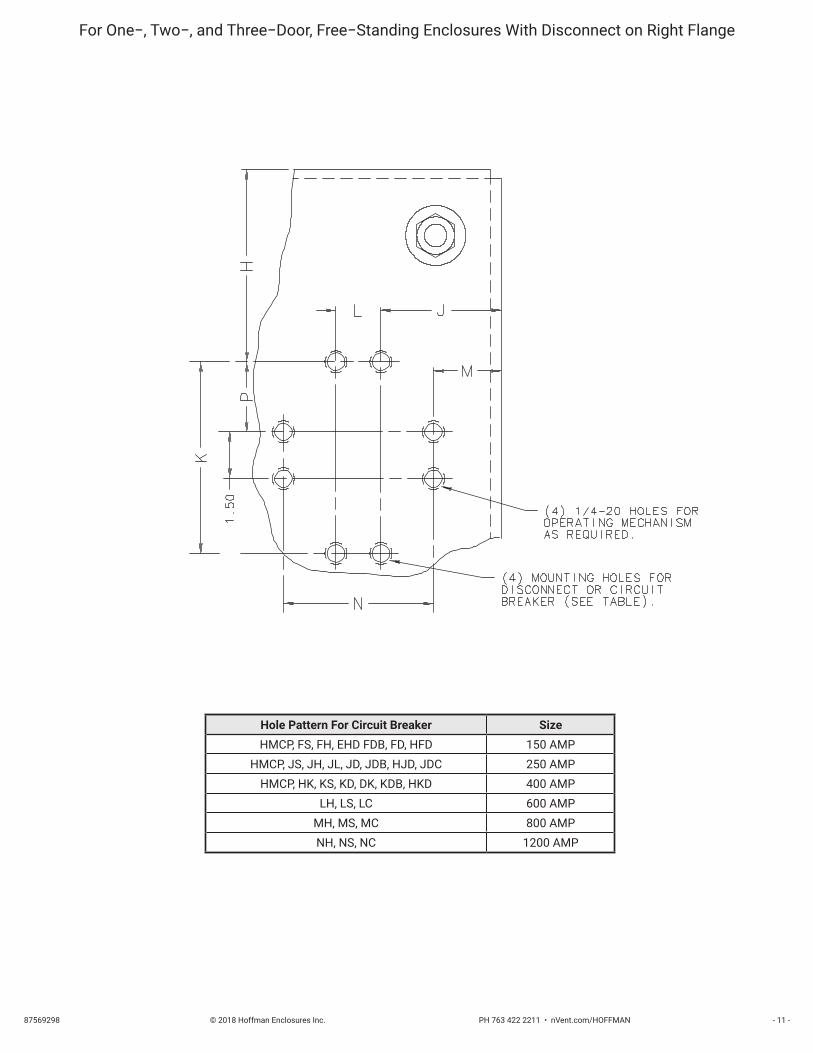
Hole Pattern For Circuit Breaker SizeHMCP, FS, FH, EHD FDB, FD, HFD 150 AMP
HMCP, JS, JH, JL, JD, JDB, HJD, JDC 250 AMPHMCP, HK, KS, KD, DK, KDB, HKD 400 AMP
LH, LS, LC 600 AMPMH, MS, MC 800 AMPNH, NS, NC 1200 AMP
For One−, Two−, and Three−Door, Free−Standing Enclosures With Disconnect on Right Flange

© 2018 Hoffman Enclosures Inc. PH 763 422 2211 • nVent.com/HOFFMAN 87569298- 12 -
For One−, Two−, and Three−Door, Free−Standing Enclosure with Disconnect on Right Flange
TABLE 1Circuit Breaker or
Disconnect Switch
FrameSize
H62.81”HIGH
H72.12”HIGH
H74.81”HIGH
H84.12”HIGH
H90.12”HIGH
J K L M N PSize of
Mounting Holes
C361NC (30A) − − − − 4.70 6.250 10.70 12.250 15.250 2.593 4.000 7.125 − − − − − − − − − − − − 10−32 UNFC361SC (30A) − − − − 4.70 6.250 10.70 12.250 15.250 2.593 4.000 9.750 − − − − − − − − − − − − 10−32 UNFC361ND (60A) − − − − 4.70 6.250 10.70 12.250 15.250 2.593 4.000 7.125 − − − − − − − − − − − − 10−32 UNFC361SD (60A) − − − − 4.70 6.250 10.70 12.250 15.250 2.593 4.000 9.750 − − − − − − − − − − − − 10−32 UNF
C361NE (100A) − − − − 4.51 6.063 10.51 12.063 15.063 2.468 5.500 7.125 − − − − − − − − − − − − 10−32 UNFC361SE (100A) − − − − 4.51 6.063 10.51 12.063 15.063 2.468 5.500 11.875 − − − − − − − − − − − − 10−32 UNF
C361NF (200A) − − − − 2.92 4.469 8.92 10.469 13.469 .938 8.500 15.500 − − − − − − − − − − − − 5/16−18UNC
C361SF (200A) − − − − 2.92 4.469 8.92 10.469 13.469 .938 8.500 15.500 − − − − − − − − − − − − 5/16−18UNC
HMCP, FS, FH,EHD, FDB, FD, HFD 150A 6.93 8.484 12.93 14.484 17.484 2.750 4.500 1.375 − − − − − − − − − − − − 8−32 UNC
JS, JH, JL 250A 6.89 8.438 12.89 14.438 17.438 3.250 7.250 1.375 .438 6.948 2.750 10−32 UNFHMCP 250A 6.89 8.438 12.89 14.438 17.438 3.250 7.250 1.375 .438 6.948 2.750 1/4−20 UNC
KH, KS, DK, KDB,KD, HKD, KDC 400A 6.45 8.000 12.45 14.000 17.000 3.078 8.438 1.719 .438 6.948 3.180 1/4−20 UNC
HMCP 400A 6.45 8.000 12.45 14.000 17.000 3.078 8.438 1.719 .438 6.948 4.000 1/4−20 UNCLH, LS, LC 600A 4.56 6.109 10.56 12.109 15.109 4.000 9.530 2.750 .359 10.050 4.320 1/4−20 UNC
MH, MS, MC 800A N/A DO NOTINSTALL N/A 8.547 11.547 4.000 14.750 2.750 .359 10.050 7.880 1/4−20 UNC
NH, HS, HC 1200A N/A DO NOTINSTALL N/A 8.457 11.547 4.000 14.750 2.750 .359 10.050 7.880 1/4−20 UNC
TABLE 2
Hoffman Disconnect Enclosure DescriptionEnclosure Depth Cutler−Hammer
C D (1)
One− and Two−Door, Free−StandingDisconnect on Right Flange
18.13 10.91
20.13 16.91 (2)24.13 22.91 (2)
Three−Door, Free−StandingDisconnect on Right Flange
18.13 15.91
24.13 21.91 (2)
Two−Door, Free−StandingDisconnect on Right Flange
12.12 9.90
18.12 16.90 (2)
24.12 21.90 (2)
1) This dimension is used to determine length to cut Cutler−Hammer connecting rods. See Cutler−Hammer instructions
2) This dimension may be greater than the depth range of standard Cutler−Hammer connecting rods. A six inch platform is provided with 24.13 inch deep enclosures to reduce the depth for disconnect mounting. The platform can be eliminated if longer connecting rods are ordered from Cutler−Hammer. (C371−CS1 or C371−CS2)

© 2018 Hoffman Enclosures Inc. PH 763 422 2211 • nVent.com/HOFFMAN87569298 - 13 -
MasterDoorINTRODUCTION
This installation instruction is for Cutler−Hammer C361, C371 (variable depth) mechanisms. These mechanisms are for disconnect switches and circuit breakers mounted in Hoffman two−door, floor−mounted, enclosures with the disconnect on the centerpost.
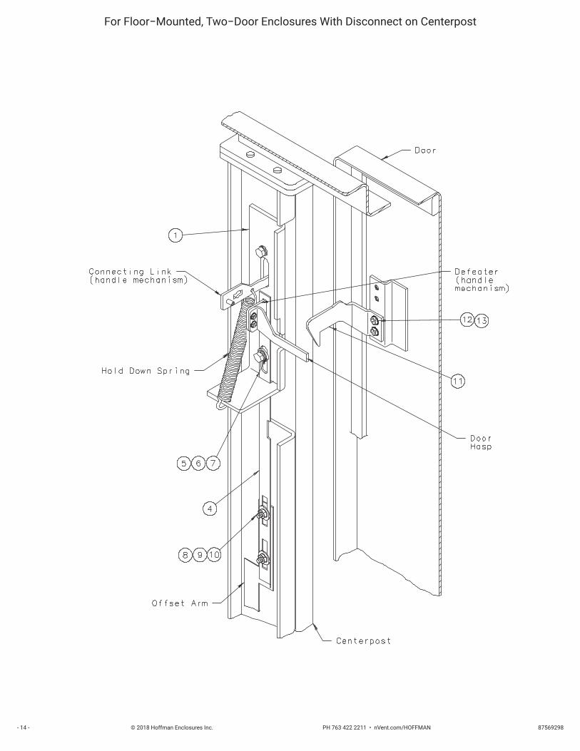
INSTALLATION STEPSStep 1 − Position Mounting plate (item 1) on the inside of the enclosure, behind the opening provided in the centerpost.
Step 2 − Discard the Cutler−Hammer spring bracket which is normally installed inside the enclosure flange behind the C−H handle mechanism.
Step 3 − Assemble the Cutler−Hammer handle mechanism through the opening in the enclosure and through the mounting plate. Omit cap screw and lockwasher which fits into bottom hole of operating handle.
Step 4 − Cut 2 1/2” off bottom end of slide arm (item 2). (bottom end has rectangular holes only)
Step 5 − Install the slide arm (item 2) through the slot in the bottom of mounting plate (item 1) and over the defeater part of the handle assembly (on C−H handle mechanism). as shown. Place the smaller diameter end of the shoulder collar (item 3) through the oval slot in the slide arm. Install long cap screw (item 4) with lockwasher (item 5) through shoulder collar into the bottom mounting hole of the C−H handle mechanism and tighten. The slide arm and defeater should move up and down smoothly. Install door hasp (C−H part) per Cutler−Hammer instructions.
Step 6 − Attach the bottom of the slide arm (item 2) to the offset arm of the lock release mechanism. Use two flat washers (item 6), two lockwashers (item 7), and two hex nuts (item 8). Do not tighten until parts are adjusted.
Step 7 − Adjust the length of the slide arm assembly. With proper adjustment of the slide arm, the safety lock (on Cutler−Hammer handle mechanism) should release just before the master door is fully latched. Lengthen slide arm if safety lock releases too soon. Shorten slide arm if safety lock releases too late.
Step 8 − Attach the door catch (item 9), provided by Hoffman, to the tapped spacer on the door using the bottom set of mounting holes. Use two screws (item 10) and lockwashers (item 11). The door catch prevents the door from being opened when the handle mechanism is in the “ON” position. The door catch may be easily bent up or down to hook properly on the door hasp of the Cutler−Hammer handle mechanism.
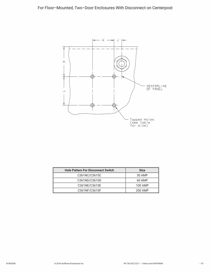
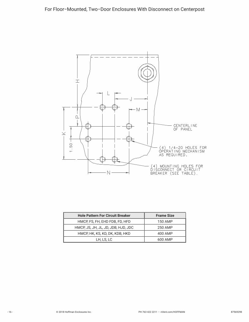
Step 9 − Drill and tap holes in panel as shown in diagram and table 1. See Cutler−Hammer instructions for locating extra holes for fuse clips.
Step 10 − Mount switch or circuit breaker using Cutler−Hammer instructions and parts. Cutler−Hammer connecting rod assembly must be cut off per Cutler−Hammer instructions. See table 2 for depth dimensions used to determine length of rod.
* NOTE: Optional channel support kit, Cutler−Hammer C371−CS6, is recommended when installing 600 AMP circuit breakers in 72 1/8” high enclosures.
© 2018 Hoffman Enclosures Inc. PH 763 422 2211 • nVent.com/HOFFMAN 87569298- 14 -
For Floor−Mounted, Two−Door Enclosures With Disconnect on Centerpost
© 2018 Hoffman Enclosures Inc. PH 763 422 2211 • nVent.com/HOFFMAN87569298 - 15 -
For Floor−Mounted, Two−Door Enclosures With Disconnect on Centerpost
Hole Pattern For Disconnect Switch SizeC361NC/C361SC 30 AMPC361ND/C361SD 60 AMPC361NE/C361SE 100 AMPC361NF/C361SF 200 AMP
© 2018 Hoffman Enclosures Inc. PH 763 422 2211 • nVent.com/HOFFMAN 87569298- 16 -
For Floor−Mounted, Two−Door Enclosures With Disconnect on Centerpost
Hole Pattern For Circuit Breaker Frame SizeHMCP, FS, FH, EHD FDB, FD, HFD 150 AMP
HMCP, JS, JH, JL, JD, JDB, HJD, JDC 250 AMPHMCP, HK, KS, KD, DK, KDB, HKD 400 AMP
LH, LS, LC 600 AMP

© 2018 Hoffman Enclosures Inc. PH 763 422 2211 • nVent.com/HOFFMAN87569298 - 17 -
TABLE 1
Circuit Breaker orDisconnect Switch
FrameSize
H60.12”HIGH
H72.12”HIGH
J K L M N P Size ofMounting Holes
C361NC (30A) − − − − 4.250 10.250 3.781 4.000 7.125 − − − − − − − − − − − − 10−32 UNFC361SC (30A) − − − − 4.250 10.250 3.781 4.000 9.750 − − − − − − − − − − − − 10−32 UNFC361ND (60A) − − − − 4.250 10.250 3.781 4.000 7.125 − − − − − − − − − − − − 10−32 UNFC361SD (60A) − − − − 4.250 10.250 3.781 4.000 9.750 − − − − − − − − − − − − 10−32 UNF
C361NE (100A) − − − − 4.063 10.063 3.656 5.500 7.125 − − − − − − − − − − − − 10−32 UNFC361SE (100A) − − − − 4.063 10.063 3.656 5.500 11.875 − − − − − − − − − − − − 10−32 UNF
C361NF (200A) − − − − DO NOTINSTALL 8.469 2.125 8.500 15.500 − − − − − − − − − − − − 5/16−18 UNC
C361SF (200A) − − − − DO NOTINSTALL 8.469 2.125 8.500 15.500 − − − − − − − − − − − − 5/16−18 UNC
HMCP, FS, FH, EHD,FDB, FD, HFD 150A 6.484 12.484 3.922 4.500 1.375 − − − − − − − − − − − − 8−32 UNC
JS, JH, JL 250A 6.438 12.438 4.438 7.250 1.375 1.610 6.948 2.750 10−32 UNFHMCP 250A 6.438 12.438 4.438 7.250 1.375 1.610 6.948 2.750 1/4−20 UNC
KH, KS, DK, KDB, KD, HKD, KDC 400A 6.000 12.000 4.266 8.438 1.719 1.610 6.948 3.180 1/4−20 UNC
HMCP 400A 6.000 12.000 4.266 8.438 1.719 1.610 6.948 4.000 1/4−20 UNC
LH, LS, LC 600A DO NOTINSTALL 10.094 5.188 9.53 2.750 1.532 10.050 4.320 1/4−20 UNC
For Floor−Mounted, Two−Door Enclosure With Disconnect on Centerpost
TABLE 2
Hoffman Disconnect Enclosure DescriptionEnclosure Depth Cutler−Hammer
C D (1)
Two−Door, Floor−MountedDisconnect on Centerpost
12.13 10.91
18.13 16.91 (2)
24.13 22.91 (2)
1) This dimension is used to determine length to cut Cutler−Hammer connecting rods. See Cutler−Hammer instructions
2) This dimension may be greater than the depth range of standard Cutler−Hammer connecting rods. A six inch platform is provided wi th 24.13 inchdeep enclosures to reduce the depth for disconnect mounting. The platform can be eliminated if longer connecting rods are ordered from Cutler−Hammer. (C371−CS1 or C371−CS2)

© 2018 Hoffman Enclosures Inc. PH 763 422 2211 • nVent.com/HOFFMAN 87569298- 18 -
MasterDoor Master
Door
MasterDoor
Two−door enclosure withdisconnect on right flange
Two−door enclosure withdisconnect on centerpost
One−, two−, and three−door enclosurewith disconnect on right flange
INTRODUCTIONThis installation instruction is for Cutler−Hammer C371 Flex ShaftTM (flexible cable) mechanisms. These mechanisms are for circuit breakers mounted in Hoffman disconnect enclosures.
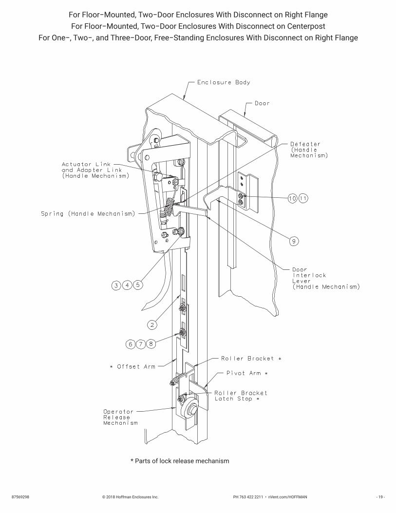
INSTALLATION STEPSStep 1 − Discard Hoffman mounting plate (item 1) which is not required for this installation.
Step 2 − Assemble the Cutler−Hammer Flex ShaftTM handle mechanism and cable toggle mechanism to the enclosure flange opening. Omit cap screw and lockwasher which fits into bottom hole of Cutler−Hammer handle mechanism.
Step 3 − Modify slide arm (item 2) only if it is being installed in an enclosur e with disconnect on centerpost. (cut 2.5 inches off the bottom end of slide arm. Bottom end has rectangular holes only)
Step 4 − Install the slide arm (item 2) over the defeater part of the handle assembly (on C−H handle mechanism). Place the smaller diameter end of the shoulder collar (item 3) through the oval slot in the slide arm. Install long cap screw (item 4) with lockwasher (item 5) through shoulder collar into the bottom mounting hole of the C−H handle mechanism and tighten. The slide arm and defeater should move up and down smoothly. Install door interlock lever (C−H part) per Cutler−Hammer instructions.
Step 5 − Attach the bottom of the slide arm (item 2) to the offset arm of the lock release mechanism. Use two flat washers (item 6), two lockwashers (item 7), and two hex nuts (item 8). Do not tighten until parts are adjusted. (see Step 6 − (B) )
Step 6 − The handle safety lock release mechanism is adjustable.
(A) Check the adjustment of the factory installed roller bracket on enclosures with disconnect on right flange. The door latch should hit against the latch stop portion of the roller bracket when the door is closed and latched. Adjust up or down if necessary. The attached mechanism will then provide the necessary up−down motion required to operate the release mechanism.
(B) Adjust the length of the slide arm assembly. With proper adjustment of the slide arm, the safety lock (on Cutler−Hammer handle mechanism) should release just before the master door is fully latched. Lengthen slide arm if safety lock releases too soon. Shorten slide arm if safety lock releases too late.
Step 7 − Attach the door catch (item 9), provided by Hoffman, to the tapped spacer on the door using the bottom set of mounting holes. Use two screws (item 10) and lockwashers (item 11). The door catch prevents the door from being opened when the handle mechanism is in the “ON” position. The door catch may be easily bent up or down to hook properly on the door interlock lever of the Cutler−Hammer handle mechanism.
Step 8 − Assemble the C−H linkage between outer handle assembly and the toggle mechanism (inside). See C−H Flex ShaftTM instructions.
Step 9 − Drill and tap holes in panel as shown in diagram and table. See Cutler−Hammer instructions for locating holes.
Step 10 − Mount circuit breaker and actuator mechanism using Cutler−Hammer Flex ShaftTM instructions and parts.
© 2018 Hoffman Enclosures Inc. PH 763 422 2211 • nVent.com/HOFFMAN87569298 - 19 -
For Floor−Mounted, Two−Door Enclosures With Disconnect on Right FlangeFor Floor−Mounted, Two−Door Enclosures With Disconnect on Centerpost
For One−, Two−, and Three−Door, Free−Standing Enclosures With Disconnect on Right Flange
* Parts of lock release mechanism

© 2018 Hoffman Enclosures Inc. PH 763 422 2211 • nVent.com/HOFFMAN 87569298- 20 -
For Floor−Mounted, Two−Door Enclosures With Disconnect on Right FlangeFor One−, Two−, and Three−Door, Free−Standing Enclosures With Disconnect on Right Flange
© 2018 Hoffman Enclosures Inc. PH 763 422 2211 • nVent.com/HOFFMAN87569298 - 21 -
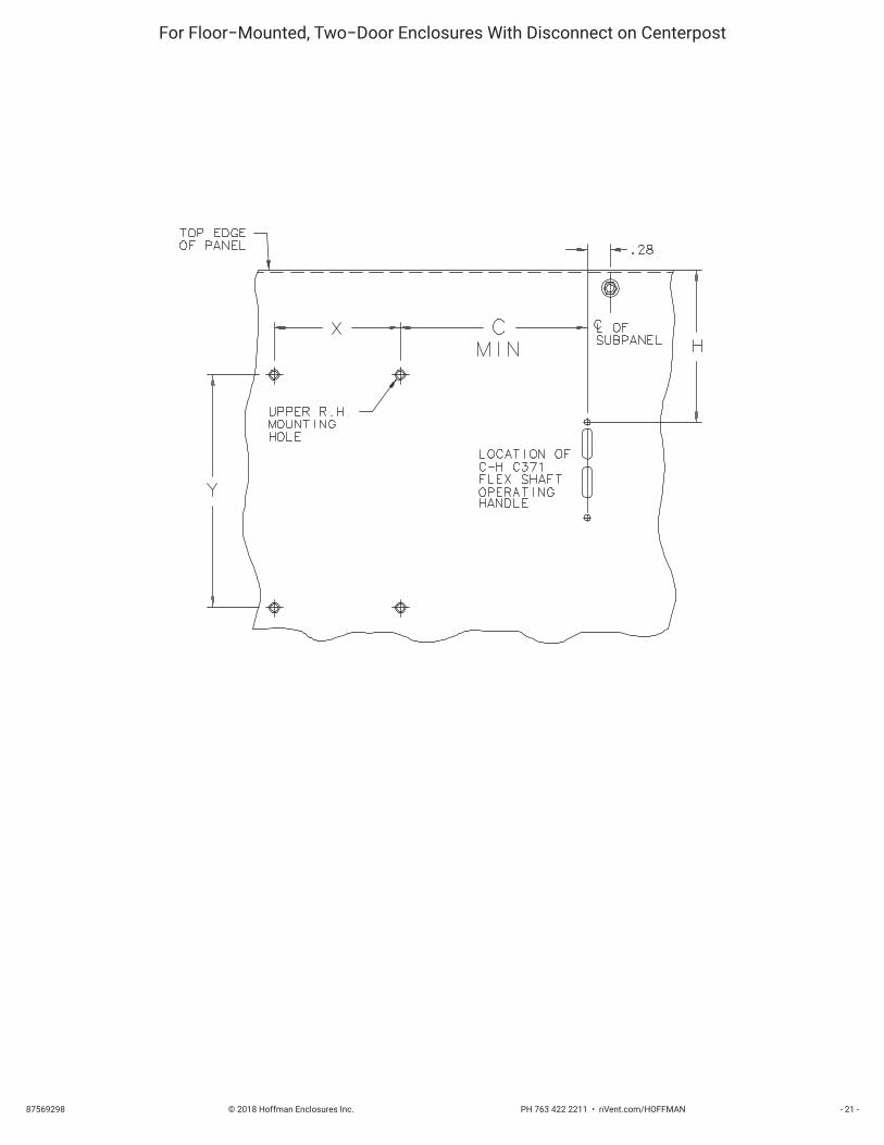
For Floor−Mounted, Two−Door Enclosures With Disconnect on Centerpost

© 2018 Hoffman Enclosures Inc. PH 763 422 2211 • nVent.com/HOFFMAN 87569298- 22 -
For Floor−Mounted, Two−Door Enclosures With Disconnect on Right FlangeFor Floor−Mounted, Two−Door Enclosures With Disconnect on Centerpost
For One−, Two−, and Three−Door, Free−Standing Enclosures With Disconnect on Right Flange
TABLE 2Location of Disconnect Operating Handle
Hoffman Disconnect Enclosure Description Enclosure Height H
Two−Door, Floor−MountedDisconnect on Right Flange
60.13 5.81
72.13 11.81
Two−Door, Floor−MountedDisconnect on Centerpost
60.13 5.81
72.13 11.81
One−, Two−, and Three−Door, Modular Free−StandingDisconnect on Right Flange
72.13 7.81
84.13 13.81
90.13 16.81
Two−Door, Free−StandingDisconnect on Right Flange
62.81 6.2674.81 12.26
TABLE 1Subpanel Drilling
Circuit BreakerFrame Size Hole Size X Y Cmin
F 8−32 1.375 4.500 1.38J 1/4−20 1.375 7.250 1.38K 1/4−20 1.719 8.438 1.88

© 2018 Hoffman Enclosures Inc. PH 763 422 2211 • nVent.com/HOFFMAN 87569298Rev. E P/N 87416628

© 2018 Hoffman Enclosures Inc. PH 763 422 2211 • nVent.com/HOFFMAN 87569298Rev. E P/N 87416628