Embed Size (px)
Citation preview
- 1 -
Operations Manual
Eagle 2000 Series Stretch Wrapper
Models B, BE, BHS, EB, EBT, BWS

- 2 -
READ ALL INSTRUCTIONS CONTAINED IN THIS
MANUAL PRIOR TO MACHINE INSTALLATION!
- 3 -
Contents page
1. Machine Safety Information
1.1 Safety & Warnings 3
1.2 Specifications 5
1.3 Outline & Applications 8
1.4 Position of Operation 8
1.5 Safety Precautions Prior to Operation 8
2. Machine Installation
2.1 Machine Structure & Main Components 9
2.2 Transportation 10
2.3 Installation 11
2.4 Operational Environment 14
3. Operation
3.1 Operational Steps & Film Loading 15
3.2 Basic Machine Operation 16
3.3 LCD Screen Operation 17
3.4 LCD Screen Navigation & Language 19
3.5 Password Settings 24
4. Weight Scales (Optional)
4.1 Introduction 26
4.2 Error Codes 28
5. Maintenance & Troubleshooting
5.1 Troubleshooting Guide 29
5.2 Carriage Load Safety Switch 31
5.3 Turntable Home Switch 32
5.4 Turntable & Carriage Adjustment 34
6. Illustrations & Parts List
6.1 Base (Turntable) 35
6.2 Idler Roller 37
6.3 Mast 38
6.4 Carriage 40
6.5 Film Roller 42
6.6 Extended Rollers 43
7. Electrical Schematics 44
- 4 -
1.1 Safety & Warnings
▪ Before servicing, always power down and unplug the machine from the power source.
▪ Ensure that the correct voltage is being supplied from the power source.
▪ Do not touch the turn table while machine is in operation.
▪ Place all items to be wrapped in the center of the turntable.
▪ Keep the machine and surrounding area clean, clear and free of debris to ensure safe operation.
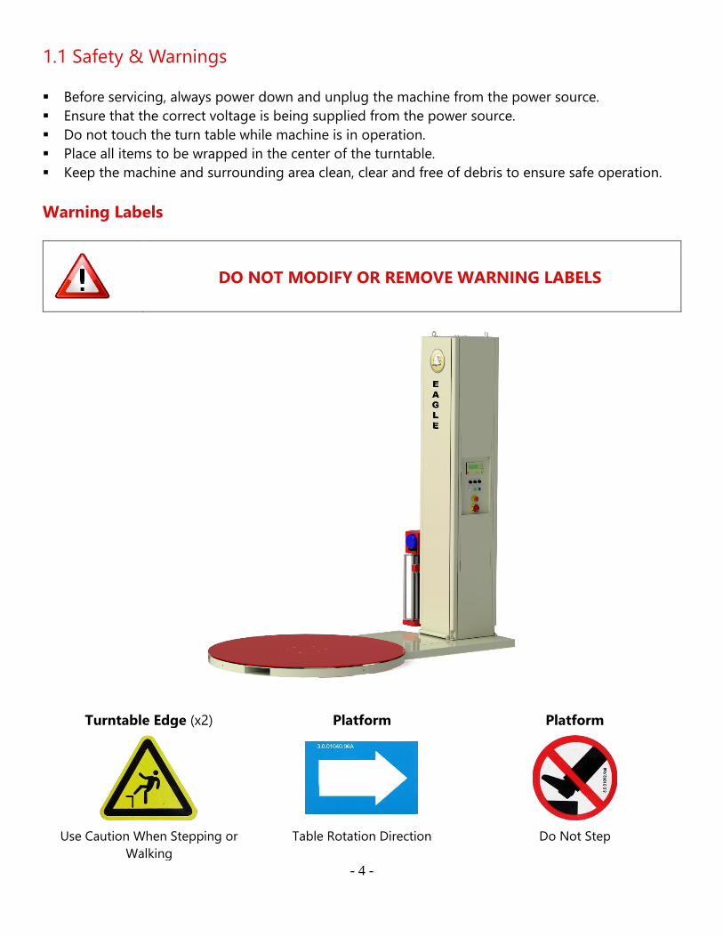
Warning Labels
DO NOT MODIFY OR REMOVE WARNING LABELS
Turntable Edge (x2) Platform Platform
Use Caution When Stepping or
Walking
Table Rotation Direction Do Not Step
- 5 -
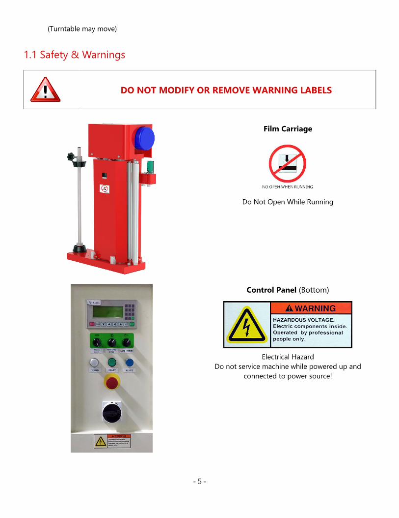
1.1 Safety & Warnings
DO NOT MODIFY OR REMOVE WARNING LABELS
Film Carriage
Do Not Open While Running
Control Panel (Bottom)
Electrical Hazard
Do not service machine while powered up and
connected to power source!
(Turntable may move)

- 6 -
- 7 -
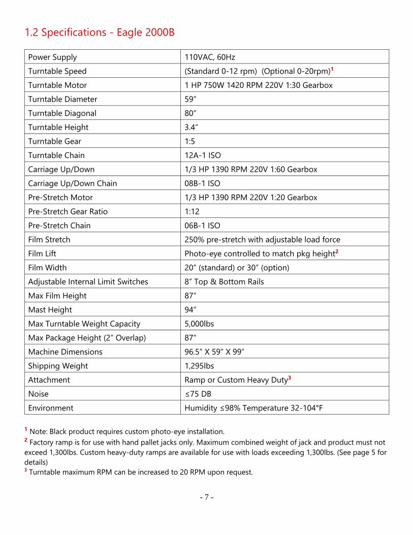
1.2 Specifications - Eagle 2000B
Power Supply 110VAC, 60Hz
Turntable Speed (Standard 0-12 rpm) (Optional 0-20rpm)1
Turntable Motor 1 HP 750W 1420 RPM 220V 1:30 Gearbox
Turntable Diameter 59”
Turntable Diagonal 80”
Turntable Height 3.4”
Turntable Gear 1:5
Turntable Chain 12A-1 ISO
Carriage Up/Down 1/3 HP 1390 RPM 220V 1:60 Gearbox
Carriage Up/Down Chain 08B-1 ISO
Pre-Stretch Motor 1/3 HP 1390 RPM 220V 1:20 Gearbox
Pre-Stretch Gear Ratio 1:12
Pre-Stretch Chain 06B-1 ISO
Film Stretch 250% pre-stretch with adjustable load force
Film Lift Photo-eye controlled to match pkg height2
Film Width 20” (standard) or 30” (option)
Adjustable Internal Limit Switches 8” Top & Bottom Rails
Max Film Height 87”
Mast Height 94”
Max Turntable Weight Capacity 5,000lbs
Max Package Height (2” Overlap) 87”
Machine Dimensions 96.5” X 59” X 99”
Shipping Weight 1,295lbs
Attachment Ramp or Custom Heavy Duty3
Noise ≤75 DB
Environment Humidity ≤98% Temperature 32-104°F
1 Note: Black product requires custom photo-eye installation. 2 Factory ramp is for use with hand pallet jacks only. Maximum combined weight of jack and product must not
exceed 1,300lbs. Custom heavy-duty ramps are available for use with loads exceeding 1,300lbs. (See page 5 for
details) 3 Turntable maximum RPM can be increased to 20 RPM upon request.
- 8 -
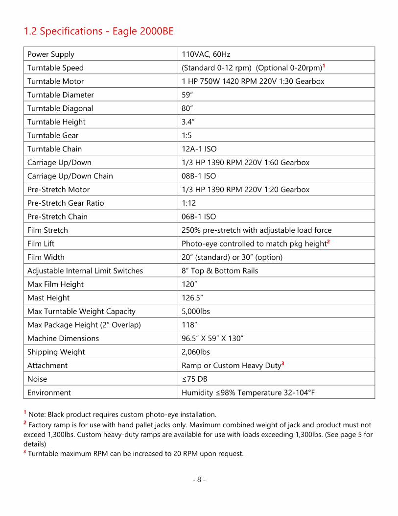
1.2 Specifications - Eagle 2000BE
Power Supply 110VAC, 60Hz
Turntable Speed (Standard 0-12 rpm) (Optional 0-20rpm)1
Turntable Motor 1 HP 750W 1420 RPM 220V 1:30 Gearbox
Turntable Diameter 59”
Turntable Diagonal 80”
Turntable Height 3.4”
Turntable Gear 1:5
Turntable Chain 12A-1 ISO
Carriage Up/Down 1/3 HP 1390 RPM 220V 1:60 Gearbox
Carriage Up/Down Chain 08B-1 ISO
Pre-Stretch Motor 1/3 HP 1390 RPM 220V 1:20 Gearbox
Pre-Stretch Gear Ratio 1:12
Pre-Stretch Chain 06B-1 ISO
Film Stretch 250% pre-stretch with adjustable load force
Film Lift Photo-eye controlled to match pkg height2
Film Width 20” (standard) or 30” (option)
Adjustable Internal Limit Switches 8” Top & Bottom Rails
Max Film Height 120”
Mast Height 126.5”
Max Turntable Weight Capacity 5,000lbs
Max Package Height (2” Overlap) 118”
Machine Dimensions 96.5” X 59” X 130”
Shipping Weight 2,060lbs
Attachment Ramp or Custom Heavy Duty3
Noise ≤75 DB
Environment Humidity ≤98% Temperature 32-104°F
1 Note: Black product requires custom photo-eye installation. 2 Factory ramp is for use with hand pallet jacks only. Maximum combined weight of jack and product must not
exceed 1,300lbs. Custom heavy-duty ramps are available for use with loads exceeding 1,300lbs. (See page 5 for
details) 3 Turntable maximum RPM can be increased to 20 RPM upon request.
- 9 -
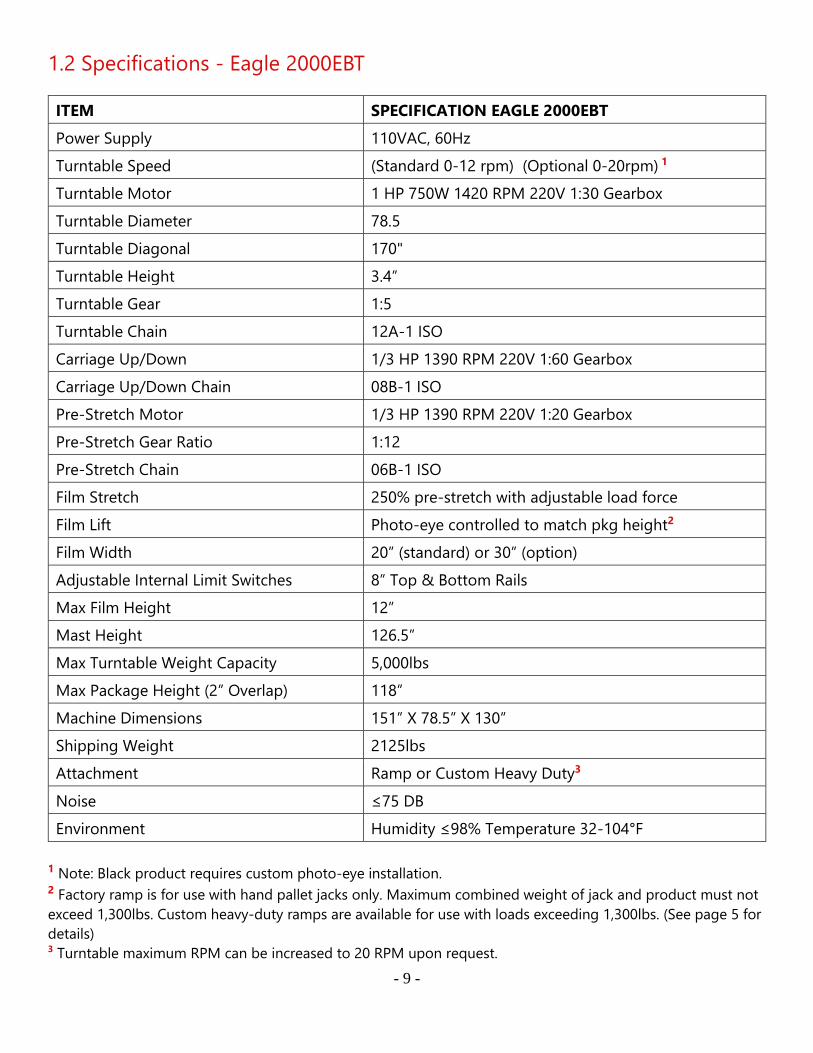
1.2 Specifications - Eagle 2000EBT
ITEM SPECIFICATION EAGLE 2000EBT
Power Supply 110VAC, 60Hz
Turntable Speed (Standard 0-12 rpm) (Optional 0-20rpm) 1
Turntable Motor 1 HP 750W 1420 RPM 220V 1:30 Gearbox
Turntable Diameter 78.5
Turntable Diagonal 170"
Turntable Height 3.4”
Turntable Gear 1:5
Turntable Chain 12A-1 ISO
Carriage Up/Down 1/3 HP 1390 RPM 220V 1:60 Gearbox
Carriage Up/Down Chain 08B-1 ISO
Pre-Stretch Motor 1/3 HP 1390 RPM 220V 1:20 Gearbox
Pre-Stretch Gear Ratio 1:12
Pre-Stretch Chain 06B-1 ISO
Film Stretch 250% pre-stretch with adjustable load force
Film Lift Photo-eye controlled to match pkg height2
Film Width 20” (standard) or 30” (option)
Adjustable Internal Limit Switches 8” Top & Bottom Rails
Max Film Height 12”
Mast Height 126.5”
Max Turntable Weight Capacity 5,000lbs
Max Package Height (2” Overlap) 118”
Machine Dimensions 151” X 78.5” X 130”
Shipping Weight 2125lbs
Attachment Ramp or Custom Heavy Duty3
Noise ≤75 DB
Environment Humidity ≤98% Temperature 32-104°F
1 Note: Black product requires custom photo-eye installation. 2 Factory ramp is for use with hand pallet jacks only. Maximum combined weight of jack and product must not
exceed 1,300lbs. Custom heavy-duty ramps are available for use with loads exceeding 1,300lbs. (See page 5 for
details) 3 Turntable maximum RPM can be increased to 20 RPM upon request.
- 10 -
1.3 Outline and Application Field
This machine features a PLC controller. The electric subassembly uses world famous products such as
OMRON, LG and TE components. This provides a reasonable, high reliability and convenient use for
the machine. It can advance production efficiency and prevent goods from being damaged during
transportation. This machine has a wide range of applications and is used in the following industries:
chemical, fiber, tobacco, pharmaceutical, publishing, refrigeration, etc.
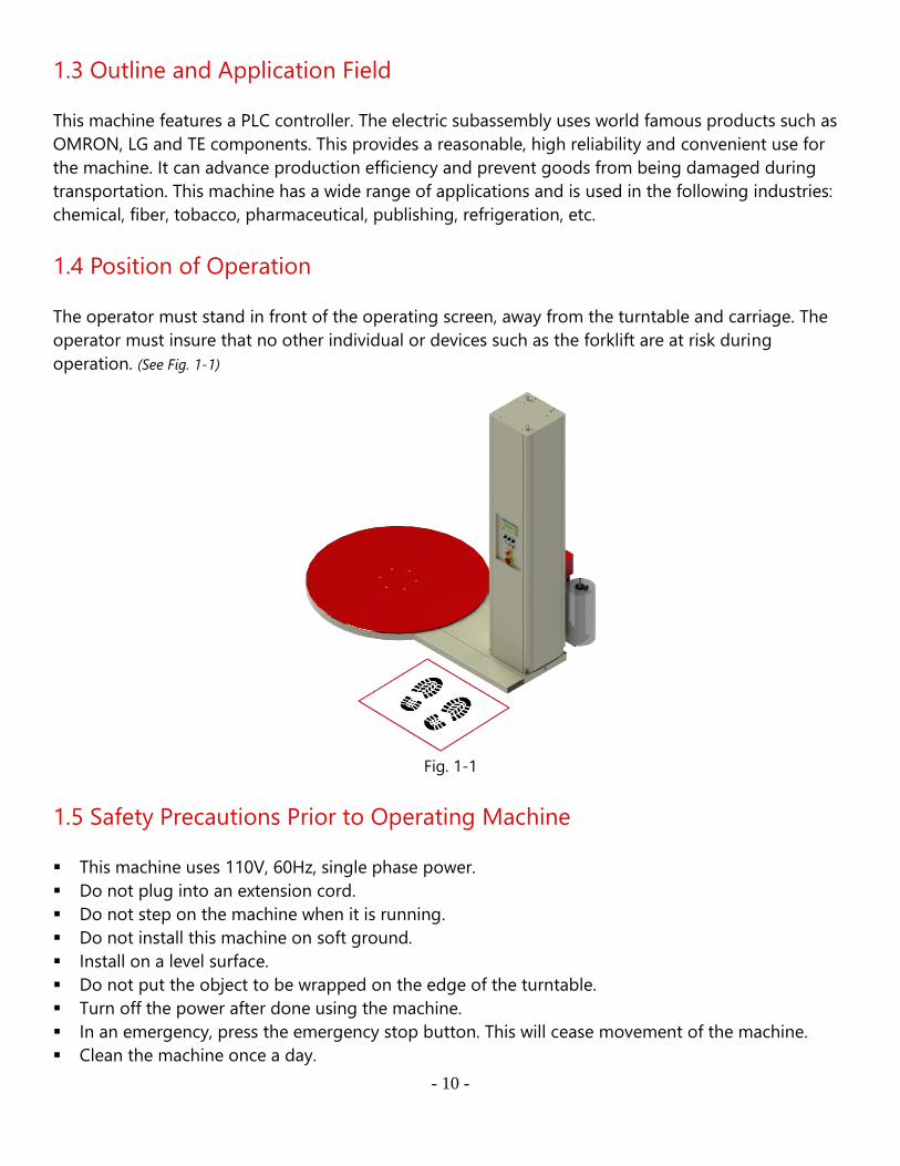
1.4 Position of Operation
The operator must stand in front of the operating screen, away from the turntable and carriage. The
operator must insure that no other individual or devices such as the forklift are at risk during
operation. (See Fig. 1-1)
Fig. 1-1
1.5 Safety Precautions Prior to Operating Machine
▪ This machine uses 110V, 60Hz, single phase power.
▪ Do not plug into an extension cord.
▪ Do not step on the machine when it is running.
▪ Do not install this machine on soft ground.
▪ Install on a level surface.
▪ Do not put the object to be wrapped on the edge of the turntable.
▪ Turn off the power after done using the machine.
▪ In an emergency, press the emergency stop button. This will cease movement of the machine.
▪ Clean the machine once a day.

- 11 -
▪ Only a Qualified Technician should change or test the wiring and/or electrical components.
▪ DO NOT push, drag, or slide machine! Doing so will cause severe damage!
- 12 -
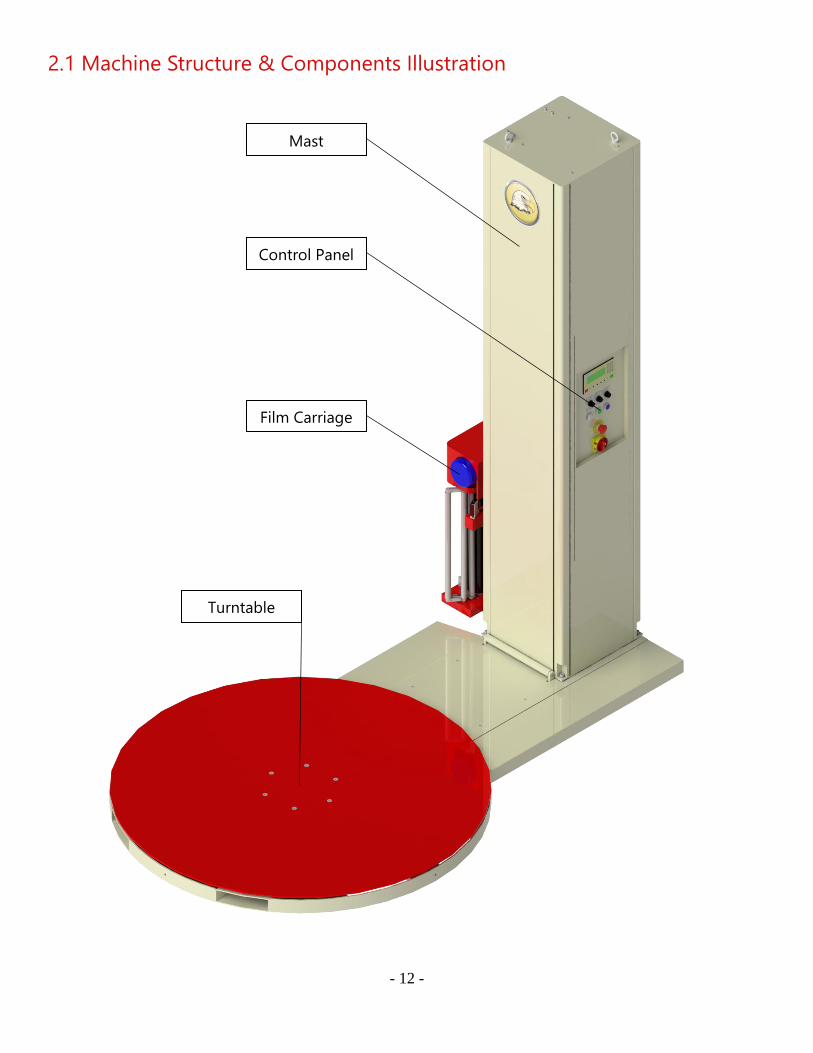
2.1 Machine Structure & Components Illustration
Mast
Control Panel
Film Carriage
Turntable

- 13 -
Fig. 2-1
- 14 -
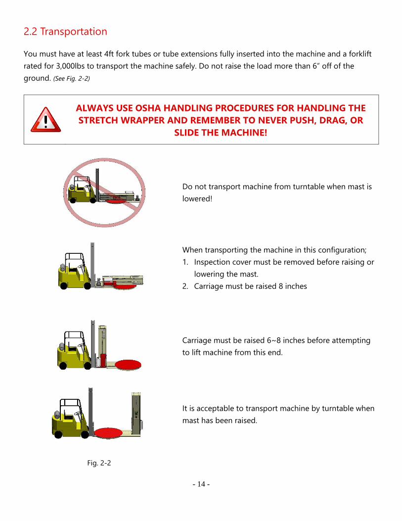
2.2 Transportation
You must have at least 4ft fork tubes or tube extensions fully inserted into the machine and a forklift
rated for 3,000lbs to transport the machine safely. Do not raise the load more than 6” off of the
ground. (See Fig. 2-2)
ALWAYS USE OSHA HANDLING PROCEDURES FOR HANDLING THE
STRETCH WRAPPER AND REMEMBER TO NEVER PUSH, DRAG, OR
SLIDE THE MACHINE!
Do not transport machine from turntable when mast is
lowered!
When transporting the machine in this configuration;
1. Inspection cover must be removed before raising or
lowering the mast.
2. Carriage must be raised 8 inches
Carriage must be raised 6~8 inches before attempting
to lift machine from this end.
It is acceptable to transport machine by turntable when
mast has been raised.
Fig. 2-2
- 15 -
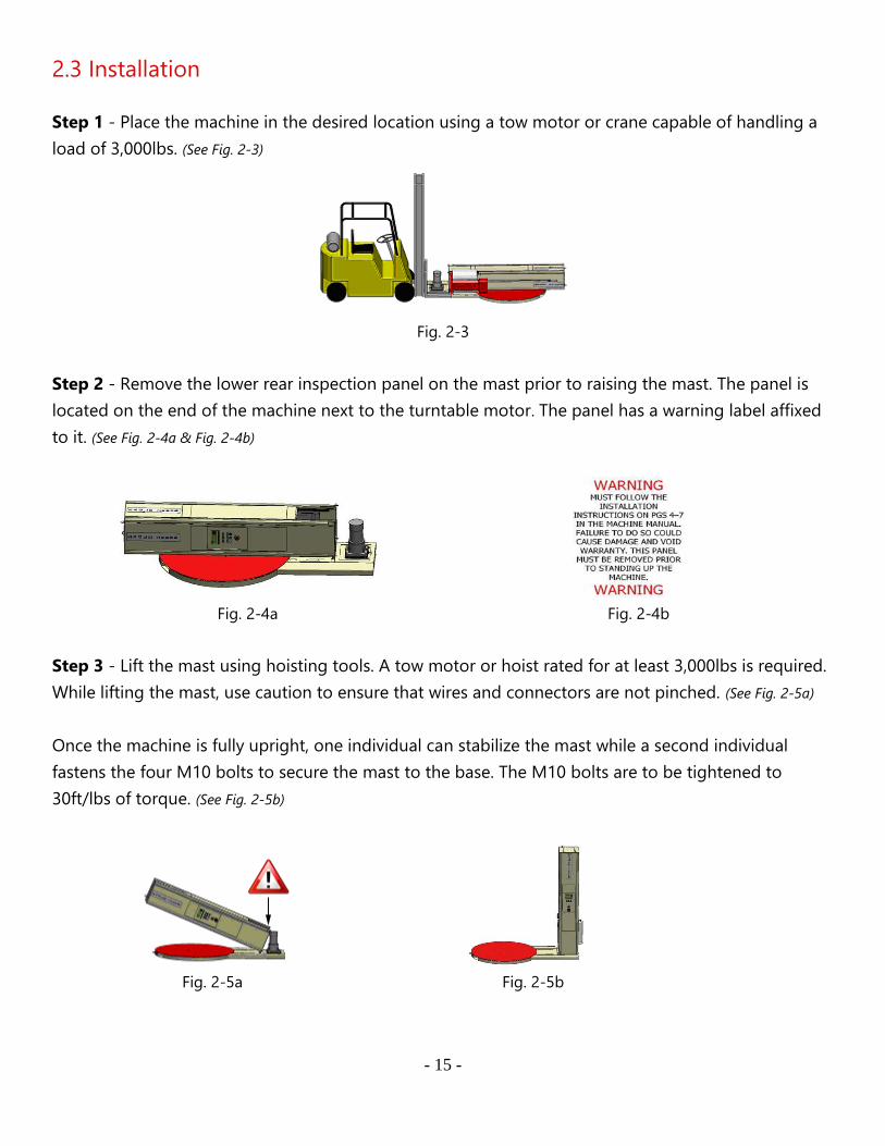
2.3 Installation
Step 1 - Place the machine in the desired location using a tow motor or crane capable of handling a
load of 3,000lbs. (See Fig. 2-3)
Fig. 2-3
Step 2 - Remove the lower rear inspection panel on the mast prior to raising the mast. The panel is
located on the end of the machine next to the turntable motor. The panel has a warning label affixed
to it. (See Fig. 2-4a & Fig. 2-4b)
Fig. 2-4a
Fig. 2-4b
Step 3 - Lift the mast using hoisting tools. A tow motor or hoist rated for at least 3,000lbs is required.
While lifting the mast, use caution to ensure that wires and connectors are not pinched. (See Fig. 2-5a)
Once the machine is fully upright, one individual can stabilize the mast while a second individual
fastens the four M10 bolts to secure the mast to the base. The M10 bolts are to be tightened to
30ft/lbs of torque. (See Fig. 2-5b)
Fig. 2-5a
Fig. 2-5b
- 16 -
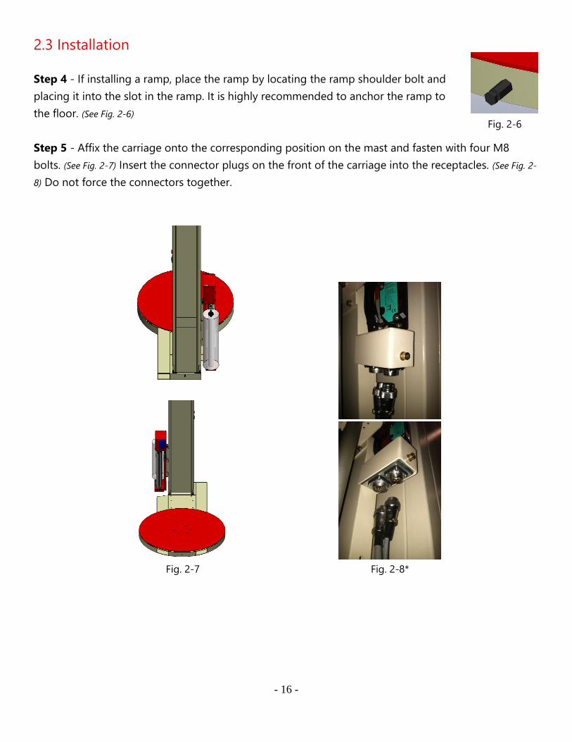
2.3 Installation
Step 4 - If installing a ramp, place the ramp by locating the ramp shoulder bolt and
placing it into the slot in the ramp. It is highly recommended to anchor the ramp to
the floor. (See Fig. 2-6)
Step 5 - Affix the carriage onto the corresponding position on the mast and fasten with four M8
bolts. (See Fig. 2-7) Insert the connector plugs on the front of the carriage into the receptacles. (See Fig. 2-
8) Do not force the connectors together.
Fig. 2-7
Fig. 2-8*
Fig. 2-6
- 17 -
2.3 Installation
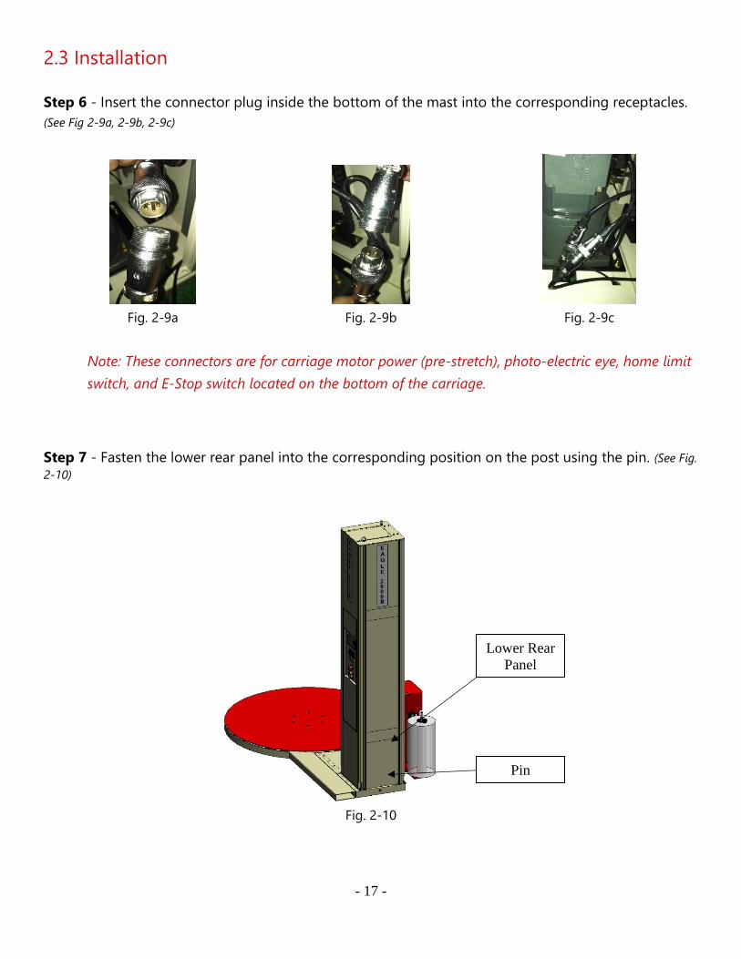
Step 6 - Insert the connector plug inside the bottom of the mast into the corresponding receptacles.
(See Fig 2-9a, 2-9b, 2-9c)
Fig. 2-9a
Fig. 2-9b
Fig. 2-9c
Note: These connectors are for carriage motor power (pre-stretch), photo-electric eye, home limit
switch, and E-Stop switch located on the bottom of the carriage.
Step 7 - Fasten the lower rear panel into the corresponding position on the post using the pin. (See Fig.
2-10)
Fig. 2-10
Lower Rear
Panel
Pin

- 18 -
Step 8 - Verify that all screws are tight and then turn on the power. Check to see if the power
indicator is on and that text is displayed on the LCD screen.
2.4 Operational Environment
• Machine should be far from smoke, preferably in a dry, well-ventilated area.
• Normal environment temperature should be within 32ºF and 104ºF.
• No special requirements for electromagnetic radiation.
• Machine should not be placed under direct lighting as it may cause photoelectric eye to
malfunction.
• DO NOT push, drag, or slide machine! Doing so will cause severe damage!
Note: If product to be wrapped is a dark color (black, dark blue, etc...), the standard photoelectric
eye may not work properly. A photo-eye upgrade option is available for sensing dark objects.
- 19 -
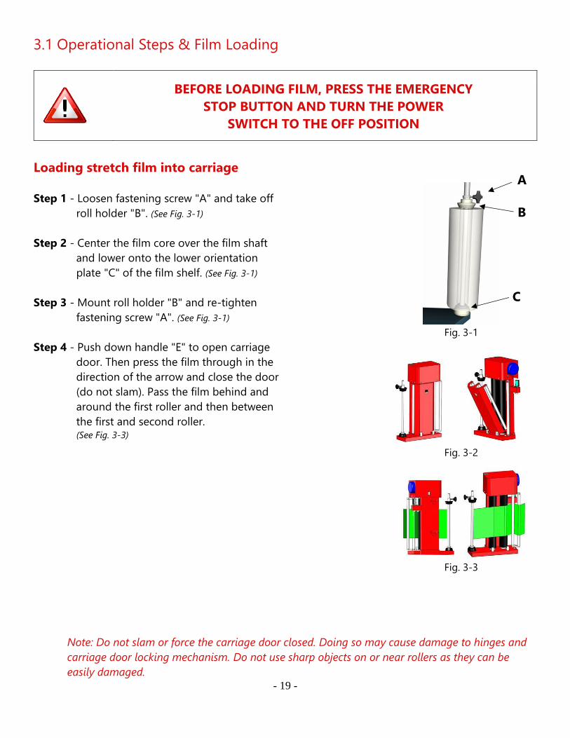
3.1 Operational Steps & Film Loading
BEFORE LOADING FILM, PRESS THE EMERGENCY
STOP BUTTON AND TURN THE POWER
SWITCH TO THE OFF POSITION
Loading stretch film into carriage
Step 1 - Loosen fastening screw "A" and take off
roll holder "B". (See Fig. 3-1)
Step 2 - Center the film core over the film shaft
and lower onto the lower orientation
plate "C" of the film shelf. (See Fig. 3-1)
Step 3 - Mount roll holder "B" and re-tighten
fastening screw "A". (See Fig. 3-1)
Step 4 - Push down handle "E" to open carriage
door. Then press the film through in the
direction of the arrow and close the door
(do not slam). Pass the film behind and
around the first roller and then between
the first and second roller. (See Fig. 3-3)
Note: Do not slam or force the carriage door closed. Doing so may cause damage to hinges and
carriage door locking mechanism. Do not use sharp objects on or near rollers as they can be
easily damaged.
Fig. 3-1
Fig. 3-2
Fig. 3-3
A
B
C
- 20 -
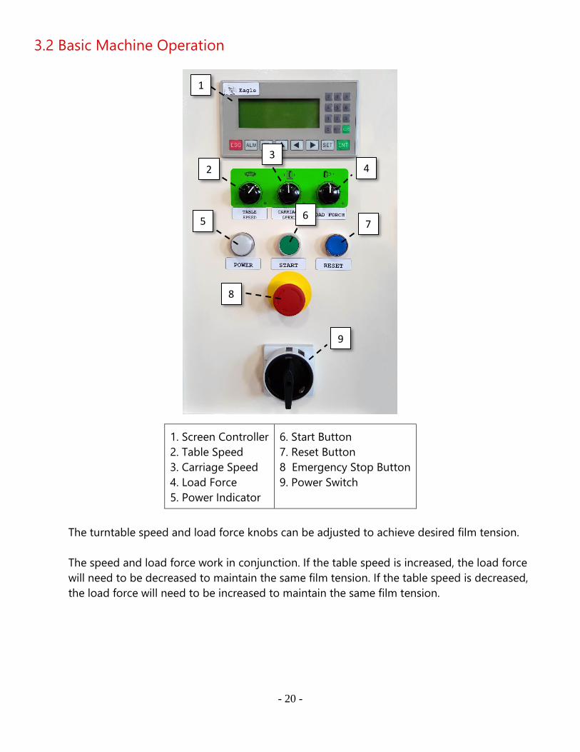
3.2 Basic Machine Operation
1. Screen Controller
2. Table Speed
3. Carriage Speed
4. Load Force
5. Power Indicator
6. Start Button
7. Reset Button
8 Emergency Stop Button
9. Power Switch
The turntable speed and load force knobs can be adjusted to achieve desired film tension.
The speed and load force work in conjunction. If the table speed is increased, the load force
will need to be decreased to maintain the same film tension. If the table speed is decreased,
the load force will need to be increased to maintain the same film tension.
1
2
3 4
5 6
7
8
9
- 21 -
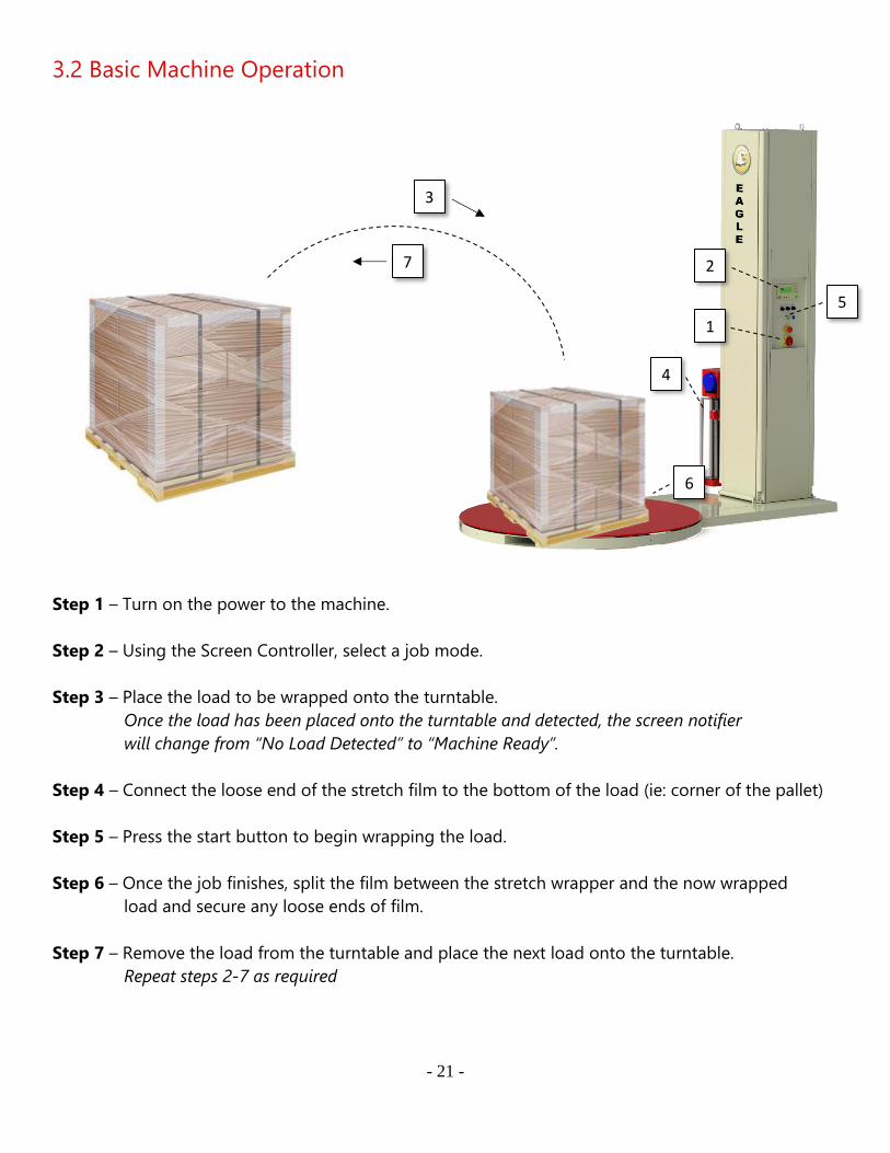
3.2 Basic Machine Operation
Step 1 – Turn on the power to the machine.
Step 2 – Using the Screen Controller, select a job mode.
Step 3 – Place the load to be wrapped onto the turntable.
Once the load has been placed onto the turntable and detected, the screen notifier
will change from “No Load Detected” to “Machine Ready”.
Step 4 – Connect the loose end of the stretch film to the bottom of the load (ie: corner of the pallet)
Step 5 – Press the start button to begin wrapping the load.
Step 6 – Once the job finishes, split the film between the stretch wrapper and the now wrapped
load and secure any loose ends of film.
Step 7 – Remove the load from the turntable and place the next load onto the turntable.
Repeat steps 2-7 as required
1
2
3
4
5
6
7
- 22 -
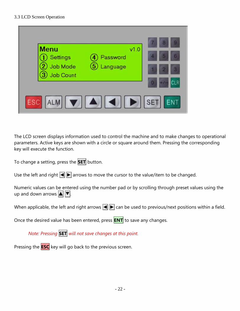
3.3 LCD Screen Operation
The LCD screen displays information used to control the machine and to make changes to operational
parameters. Active keys are shown with a circle or square around them. Pressing the corresponding
key will execute the function.
To change a setting, press the SET button.
Use the left and right ◄ ► arrows to move the cursor to the value/item to be changed.
Numeric values can be entered using the number pad or by scrolling through preset values using the
up and down arrows ▲ ▼ .
When applicable, the left and right arrows ◄ ► can be used to previous/next positions within a field.
Once the desired value has been entered, press ENT to save any changes.
Note: Pressing SET will not save changes at this point.
Pressing the ESC key will go back to the previous screen.
- 23 -
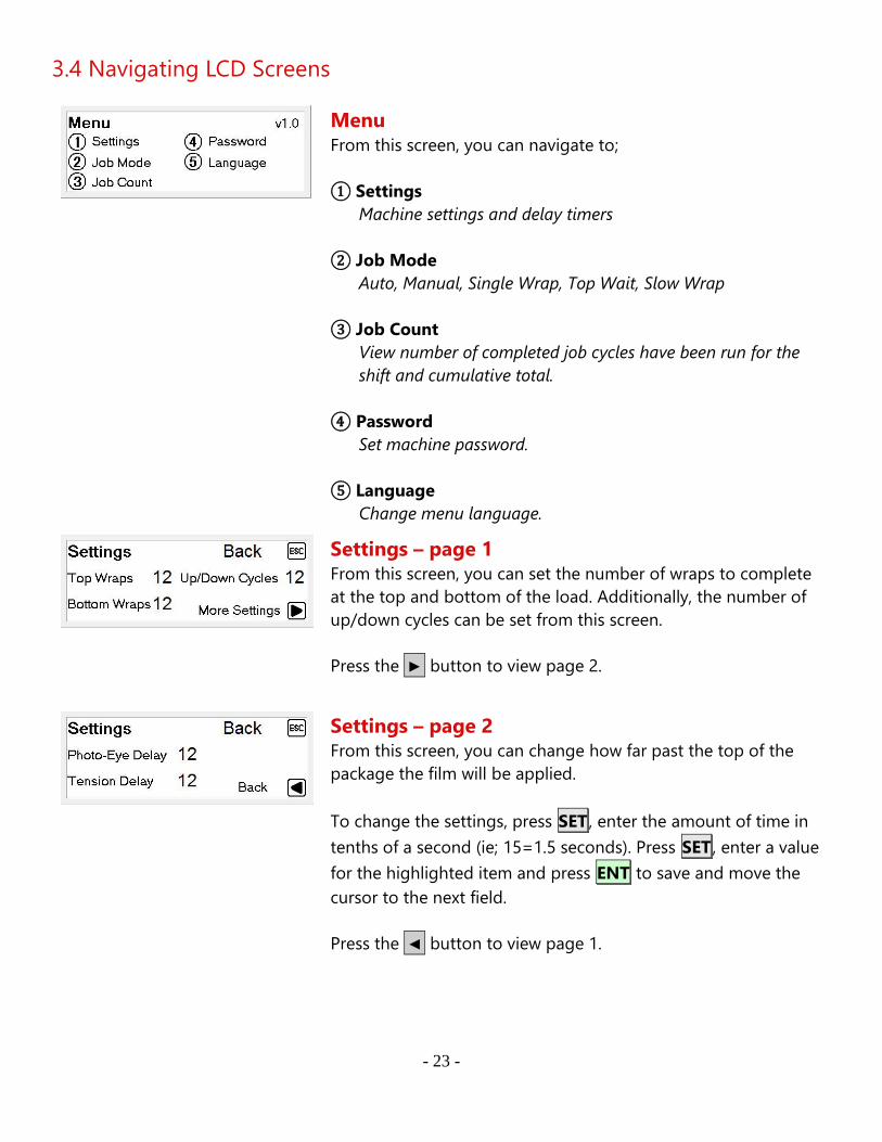
3.4 Navigating LCD Screens
Menu
From this screen, you can navigate to;
① Settings
Machine settings and delay timers
② Job Mode
Auto, Manual, Single Wrap, Top Wait, Slow Wrap
③ Job Count
View number of completed job cycles have been run for the
shift and cumulative total.
④ Password
Set machine password.
⑤ Language
Change menu language.
Settings – page 1 From this screen, you can set the number of wraps to complete
at the top and bottom of the load. Additionally, the number of
up/down cycles can be set from this screen.
Press the ► button to view page 2.
Settings – page 2 From this screen, you can change how far past the top of the
package the film will be applied.
To change the settings, press SET , enter the amount of time in
tenths of a second (ie; 15=1.5 seconds). Press SET , enter a value
for the highlighted item and press ENT to save and move the
cursor to the next field.
Press the ◄ button to view page 1.

- 24 -
- 25 -
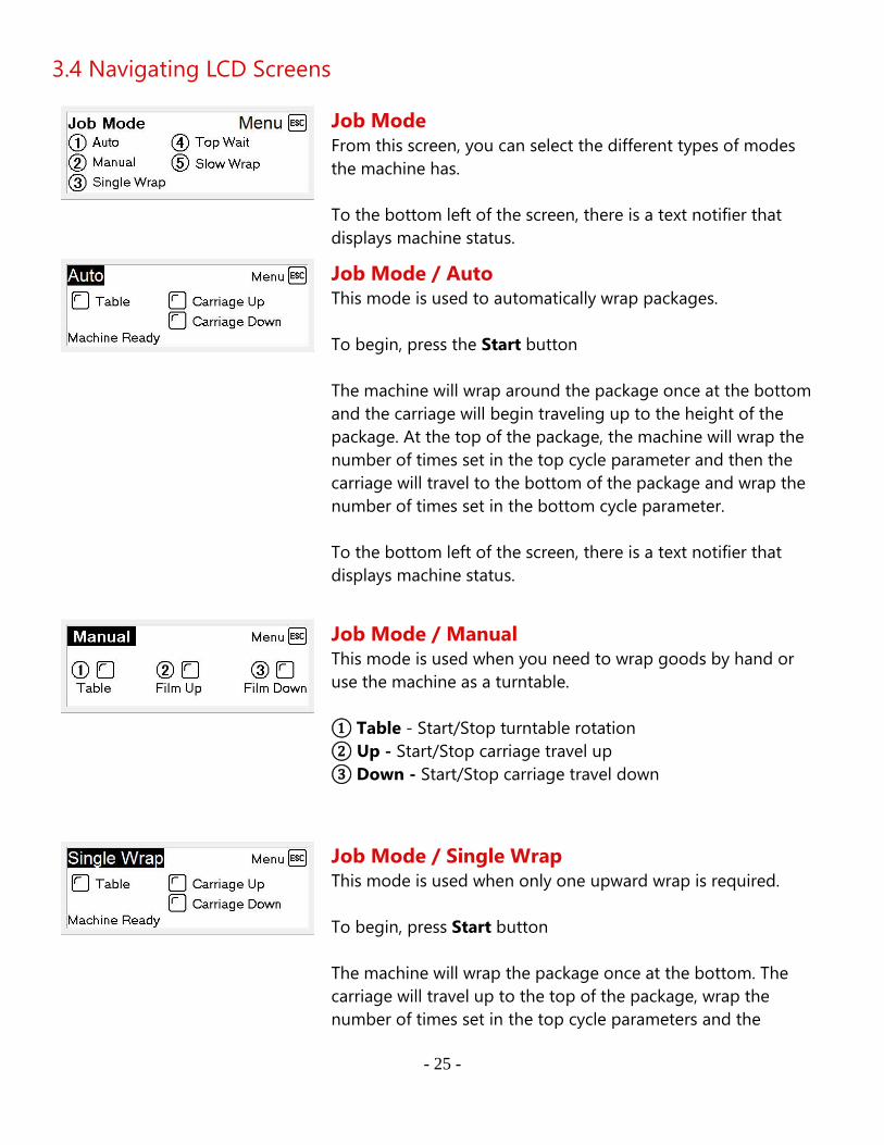
3.4 Navigating LCD Screens
Job Mode
From this screen, you can select the different types of modes
the machine has.
To the bottom left of the screen, there is a text notifier that
displays machine status.
Job Mode / Auto This mode is used to automatically wrap packages.
To begin, press the Start button
The machine will wrap around the package once at the bottom
and the carriage will begin traveling up to the height of the
package. At the top of the package, the machine will wrap the
number of times set in the top cycle parameter and then the
carriage will travel to the bottom of the package and wrap the
number of times set in the bottom cycle parameter.
To the bottom left of the screen, there is a text notifier that
displays machine status.
Job Mode / Manual This mode is used when you need to wrap goods by hand or
use the machine as a turntable.
① Table - Start/Stop turntable rotation
② Up - Start/Stop carriage travel up
③ Down - Start/Stop carriage travel down
Job Mode / Single Wrap
This mode is used when only one upward wrap is required.
To begin, press Start button
The machine will wrap the package once at the bottom. The
carriage will travel up to the top of the package, wrap the
number of times set in the top cycle parameters and the

- 26 -
turntable will stop. The carriage will then travel back down to
the bottom.
To the bottom left of the screen, there is a text notifier that
displays machine status.
- 27 -
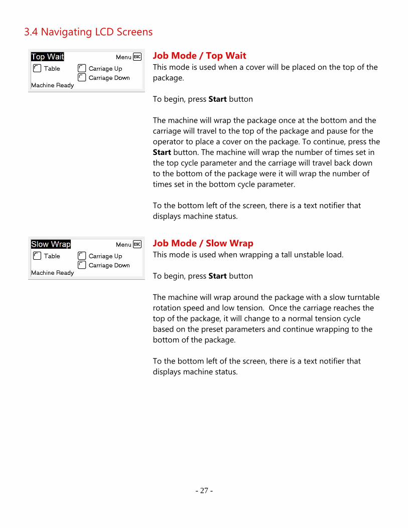
3.4 Navigating LCD Screens
Job Mode / Top Wait
This mode is used when a cover will be placed on the top of the
package.
To begin, press Start button
The machine will wrap the package once at the bottom and the
carriage will travel to the top of the package and pause for the
operator to place a cover on the package. To continue, press the
Start button. The machine will wrap the number of times set in
the top cycle parameter and the carriage will travel back down
to the bottom of the package were it will wrap the number of
times set in the bottom cycle parameter.
To the bottom left of the screen, there is a text notifier that
displays machine status.
Job Mode / Slow Wrap This mode is used when wrapping a tall unstable load.
To begin, press Start button
The machine will wrap around the package with a slow turntable
rotation speed and low tension. Once the carriage reaches the
top of the package, it will change to a normal tension cycle
based on the preset parameters and continue wrapping to the
bottom of the package.
To the bottom left of the screen, there is a text notifier that
displays machine status.
- 28 -
3.4 Navigating LCD Screens
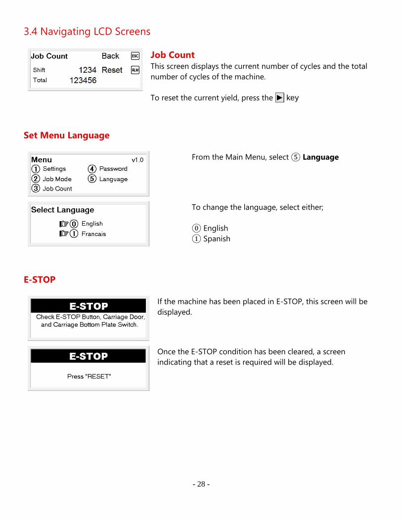
Job Count
This screen displays the current number of cycles and the total
number of cycles of the machine.
To reset the current yield, press the ► key
Set Menu Language
From the Main Menu, select ⑤ Language
To change the language, select either;
⓪ English
① Spanish
E-STOP
If the machine has been placed in E-STOP, this screen will be
displayed.
Once the E-STOP condition has been cleared, a screen
indicating that a reset is required will be displayed.

- 29 -
Film Tension Lost
If film tension is lost during a job, the machine will pause the
job and display a screen indicating film tension has been lost.
Once film tension has been restored, the job can be continued
by pressing the Start button.
- 30 -
3.4 Navigating LCD Screens
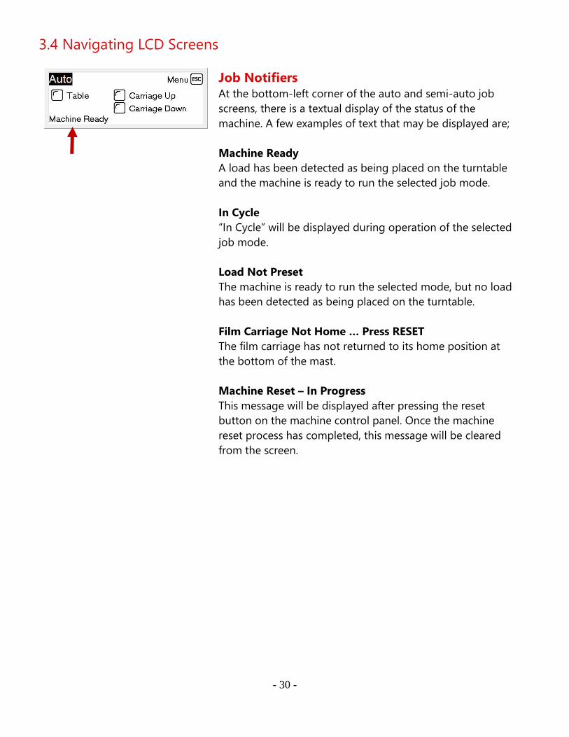
Job Notifiers
At the bottom-left corner of the auto and semi-auto job
screens, there is a textual display of the status of the
machine. A few examples of text that may be displayed are;
Machine Ready
A load has been detected as being placed on the turntable
and the machine is ready to run the selected job mode.
In Cycle
“In Cycle” will be displayed during operation of the selected
job mode.
Load Not Preset
The machine is ready to run the selected mode, but no load
has been detected as being placed on the turntable.
Film Carriage Not Home … Press RESET
The film carriage has not returned to its home position at
the bottom of the mast.
Machine Reset – In Progress
This message will be displayed after pressing the reset
button on the machine control panel. Once the machine
reset process has completed, this message will be cleared
from the screen.
- 31 -
3.5 Password Settings
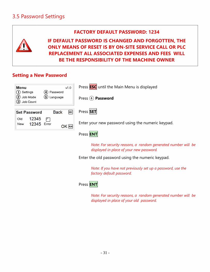
FACTORY DEFAULT PASSWORD: 1234
IF DEFAULT PASSWORD IS CHANGED AND FORGOTTEN, THE
ONLY MEANS OF RESET IS BY ON-SITE SERVICE CALL OR PLC
REPLACEMENT ALL ASSOCIATED EXPENSES AND FEES WILL
BE THE RESPONSIBILITY OF THE MACHINE OWNER
Setting a New Password
Press ESC until the Main Menu is displayed
Press ④ Password
Press SET
Enter your new password using the numeric keypad.
Press ENT
Note: For security reasons, a random generated number will be
displayed in place of your new password.
Enter the old password using the numeric keypad.
Note: If you have not previously set up a password, use the
factory default password.
Press ENT
Note: For security reasons, a random generated number will be
displayed in place of your old password.

- 32 -
3.5 Password Settings
If there is a error during the process, the screen will display
"INVALID PW, SEE MANUAL"
Press ALM to clear the error.
Note: If this message is displayed, the new password has not
been set. You will need to re-enter the new and old passwords
again.
How to Enter a Password
Any time a menu item is selected that is password protected,
the Input Password screen will be displayed.
To enter a password, press SET
The black background behind the number will clear to indicate
the system is ready for password entry.
Use the numeric keypad to enter your password.
Note: The factory default password is; 1234
Press ENT and, if the correct password was entered, the menu
will proceed to the item selected.
- 33 -
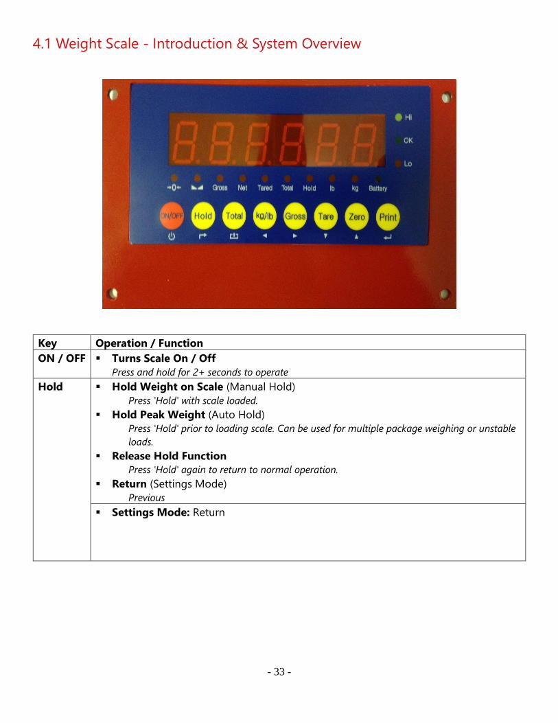
4.1 Weight Scale - Introduction & System Overview
Key Operation / Function
ON / OFF ▪ Turns Scale On / Off
Press and hold for 2+ seconds to operate
Hold ▪ Hold Weight on Scale (Manual Hold)
Press 'Hold' with scale loaded.
▪ Hold Peak Weight (Auto Hold)
Press 'Hold' prior to loading scale. Can be used for multiple package weighing or unstable
loads.
▪ Release Hold Function
Press 'Hold' again to return to normal operation.
▪ Return (Settings Mode)
Previous
▪ Settings Mode: Return
- 34 -
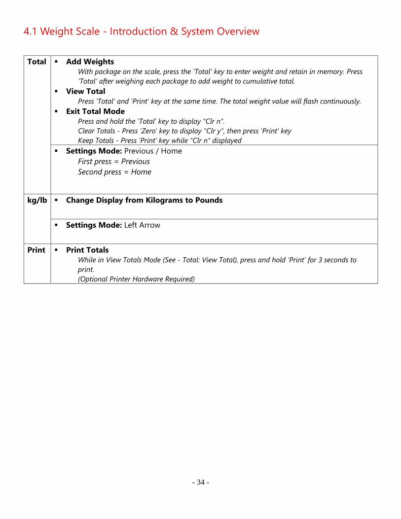
4.1 Weight Scale - Introduction & System Overview
Total ▪ Add Weights
With package on the scale, press the 'Total' key to enter weight and retain in memory. Press
'Total' after weighing each package to add weight to cumulative total.
▪ View Total
Press 'Total' and 'Print' key at the same time. The total weight value will flash continuously.
▪ Exit Total Mode
Press and hold the 'Total' key to display "Clr n".
Clear Totals - Press 'Zero' key to display "Clr y", then press 'Print' key
Keep Totals - Press 'Print' key while "Clr n" displayed
▪ Settings Mode: Previous / Home
First press = Previous
Second press = Home
kg/lb ▪ Change Display from Kilograms to Pounds
▪ Settings Mode: Left Arrow
Print ▪ Print Totals
While in View Totals Mode (See - Total: View Total), press and hold 'Print' for 3 seconds to
print.
(Optional Printer Hardware Required)
- 35 -
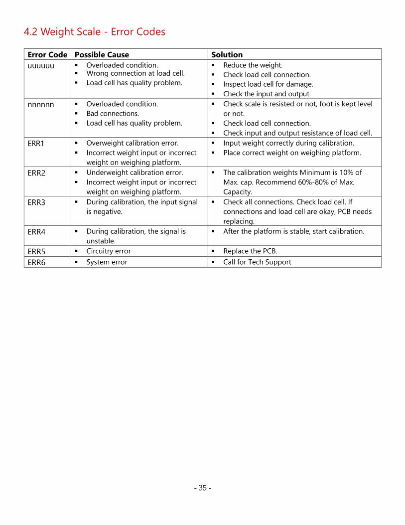
4.2 Weight Scale - Error Codes
Error Code Possible Cause Solution
uuuuuu ▪ Overloaded condition. ▪ Wrong connection at load cell.
▪ Load cell has quality problem.
▪ Reduce the weight.
▪ Check load cell connection.
▪ Inspect load cell for damage.
▪ Check the input and output.
nnnnnn ▪ Overloaded condition.
▪ Bad connections.
▪ Load cell has quality problem.
▪ Check scale is resisted or not, foot is kept level
or not.
▪ Check load cell connection.
▪ Check input and output resistance of load cell.
ERR1 ▪ Overweight calibration error.
▪ Incorrect weight input or incorrect
weight on weighing platform.
▪ Input weight correctly during calibration.
▪ Place correct weight on weighing platform.
ERR2 ▪ Underweight calibration error.
▪ Incorrect weight input or incorrect
weight on weighing platform.
▪ The calibration weights Minimum is 10% of
Max. cap. Recommend 60%-80% of Max.
Capacity.
ERR3 ▪ During calibration, the input signal
is negative.
▪ Check all connections. Check load cell. If
connections and load cell are okay, PCB needs
replacing.
ERR4 ▪ During calibration, the signal is
unstable.
▪ After the platform is stable, start calibration.
ERR5 ▪ Circuitry error ▪ Replace the PCB.
ERR6 ▪ System error ▪ Call for Tech Support

- 36 -
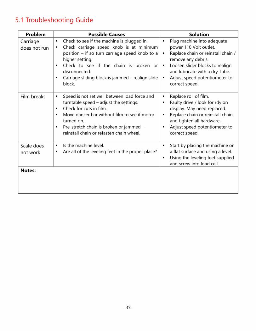
5.1 Troubleshooting Guide
Error Code Possible Cause Solution
Machine will not function ▪ Machine not plugged in.
▪ Outlet where Machine is plugged
into has no power or bad outlet.
▪ Power cord has been damaged.
▪ Machine internal circuit breaker
tripped.
▪ Plug machine into 110VAC
outlet.
▪ Check to see if outlet has power.
▪ Call service for new cord.
▪ If machine breaker is tripped call
tech support.
Machine has power and
will not function
"Machine Pause"
▪ Input signal 05 is lit on PLC.
▪ E-stop is pushed on main panel.
▪ Carriage base safety switch pushed.
▪ Film Feed Door is not closed
properly.
▪ Drive display should display "rdy"
for them to be ready.
▪ Check all E-stop and debris
under carriage.
▪ Adjustment may be needed to
carriage safety switch reference
4.2 carriage maintenance .
▪ Close door with a firm push Do
Not slam or force.
▪ If drive don't display "rdy" call
tech support.
Machine will not stop at
home
▪ Input signal 03 is not lit on PLC.
▪ Bad connection between mass and
turn table.
▪ Bad Limit Switch/ Adjustment.
▪ This Input will only illuminate
when the Limit Switch is on the
cam location.
▪ Tighten or replace connector
ensure that their no pinched
wires.
▪ Replace Limit Switch or adjust so
that rides on cam properly.
Machine will not start job
after reset
▪ Input 04 is not lit .
▪ Photoelectric Eye is not reading
package.
▪ Photoelectric Eye is not sending
a signal to PLC.
▪ Ensure that the both green and
amber are illuminated with load
in place.
▪ Call tech support
Screen displays Chinese
lettering
▪ DB9 connector has come
unplugged or is loose.
▪ DB9 connector is bad.
▪ Tighten connector on PLC and
Screen / Be sure to check power
connections as well.
▪ Replace DB9 Connector / call
tech support .
- 37 -
5.1 Troubleshooting Guide
Problem Possible Causes Solution
Carriage
does not run
▪ Check to see if the machine is plugged in.
▪ Check carriage speed knob is at minimum
position – if so turn carriage speed knob to a
higher setting.
▪ Check to see if the chain is broken or
disconnected.
▪ Carriage sliding block is jammed – realign slide
block.
▪ Plug machine into adequate
power 110 Volt outlet.
▪ Replace chain or reinstall chain /
remove any debris.
▪ Loosen slider blocks to realign
and lubricate with a dry lube.
▪ Adjust speed potentiometer to
correct speed.
Film breaks ▪ Speed is not set well between load force and
turntable speed – adjust the settings.
▪ Check for cuts in film.
▪ Move dancer bar without film to see if motor
turned on.
▪ Pre-stretch chain is broken or jammed –
reinstall chain or refasten chain wheel.
▪ Replace roll of film.
▪ Faulty drive / look for rdy on
display. May need replaced.
▪ Replace chain or reinstall chain
and tighten all hardware.
▪ Adjust speed potentiometer to
correct speed.
Scale does
not work
▪ Is the machine level.
▪ Are all of the leveling feet in the proper place?
▪ Start by placing the machine on
a flat surface and using a level.
▪ Using the leveling feet supplied
and screw into load cell.
Notes:
- 38 -
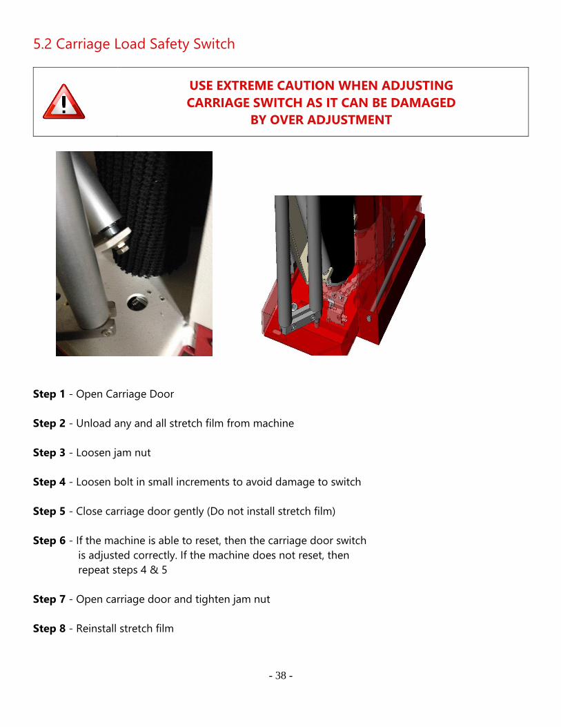
5.2 Carriage Load Safety Switch
USE EXTREME CAUTION WHEN ADJUSTING
CARRIAGE SWITCH AS IT CAN BE DAMAGED
BY OVER ADJUSTMENT
Step 1 - Open Carriage Door
Step 2 - Unload any and all stretch film from machine
Step 3 - Loosen jam nut
Step 4 - Loosen bolt in small increments to avoid damage to switch
Step 5 - Close carriage door gently (Do not install stretch film)
Step 6 - If the machine is able to reset, then the carriage door switch
is adjusted correctly. If the machine does not reset, then
repeat steps 4 & 5
Step 7 - Open carriage door and tighten jam nut
Step 8 - Reinstall stretch film
- 39 -
5.3 Turntable Home Switch
BE SURE TO DISCONNECT ALL POWER TO THE MACHINE PRIOR TO
ANY MAINTENANCE WORK
Fig. 4-1
Fig. 4-2
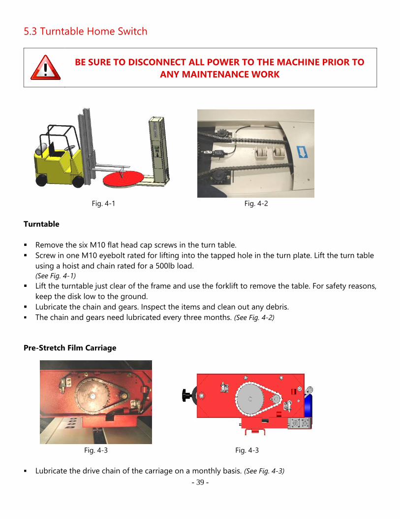
Turntable
▪ Remove the six M10 flat head cap screws in the turn table.
▪ Screw in one M10 eyebolt rated for lifting into the tapped hole in the turn plate. Lift the turn table
using a hoist and chain rated for a 500lb load.
(See Fig. 4-1)
▪ Lift the turntable just clear of the frame and use the forklift to remove the table. For safety reasons,
keep the disk low to the ground.
▪ Lubricate the chain and gears. Inspect the items and clean out any debris.
▪ The chain and gears need lubricated every three months. (See Fig. 4-2)
Pre-Stretch Film Carriage
Fig. 4-3
Fig. 4-3
▪ Lubricate the drive chain of the carriage on a monthly basis. (See Fig. 4-3)
- 40 -
5.3 Turntable Home Switch
Fig. 4-4
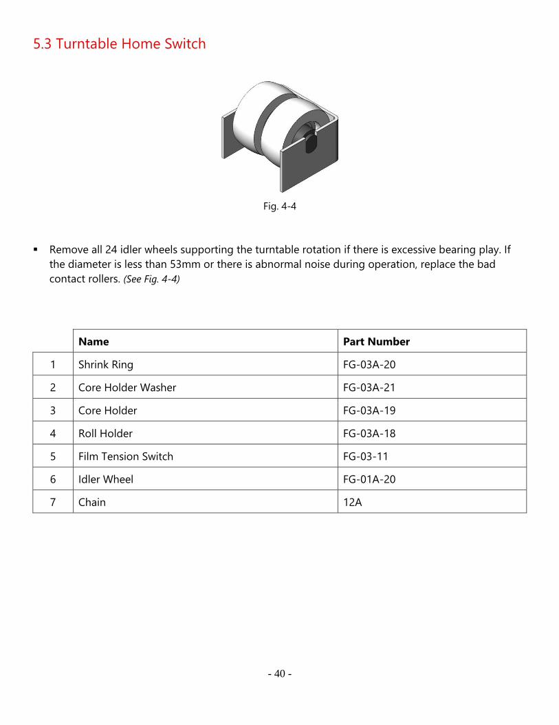
▪ Remove all 24 idler wheels supporting the turntable rotation if there is excessive bearing play. If
the diameter is less than 53mm or there is abnormal noise during operation, replace the bad
contact rollers. (See Fig. 4-4)
Name Part Number
1 Shrink Ring FG-03A-20
2 Core Holder Washer FG-03A-21
3 Core Holder FG-03A-19
4 Roll Holder FG-03A-18
5 Film Tension Switch FG-03-11
6 Idler Wheel FG-01A-20
7 Chain 12A
- 41 -
5.4 Turntable & Carriage Adjustment
Test Operation
Turntable
▪ Turn on the power
▪ From the Main Menu, press;
o ② Job Mode
o ② Manual Mode
o ① Turntable (starts turntable rotation)
o ① Turntable (stops turntable rotation)
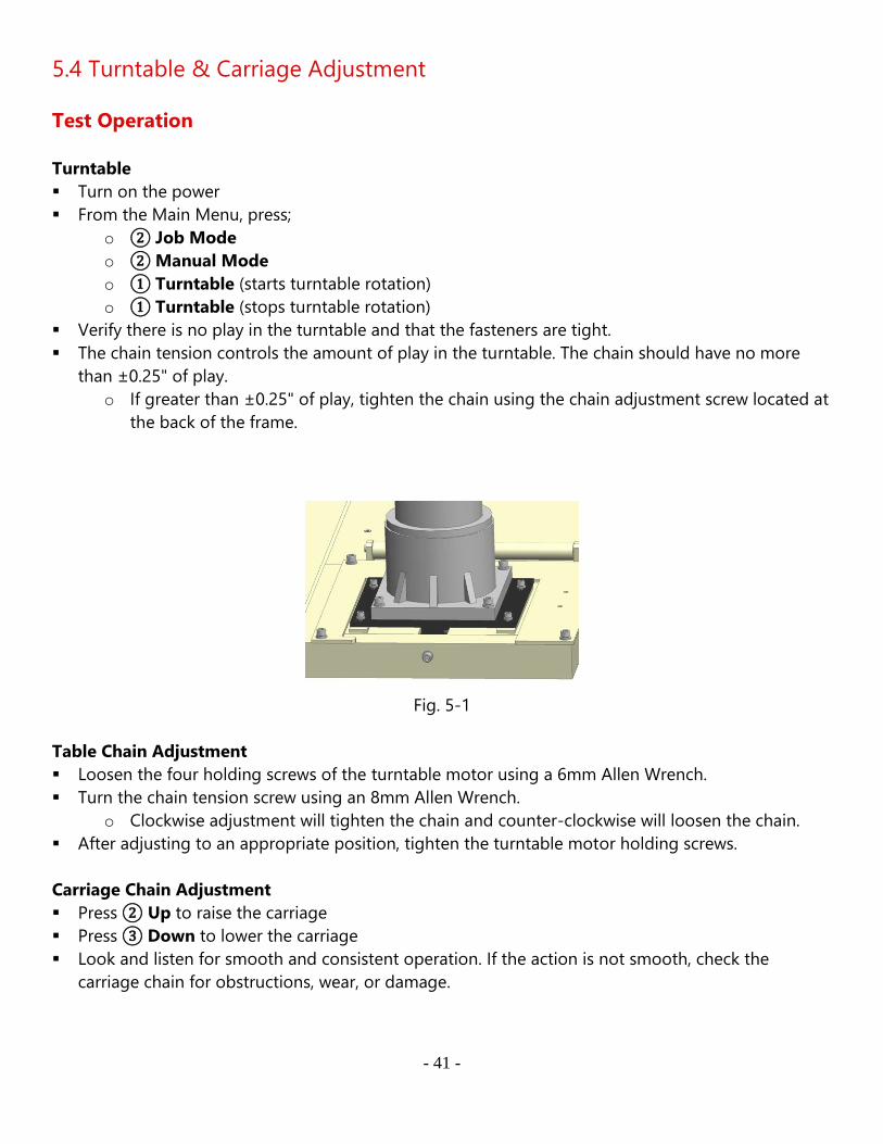
▪ Verify there is no play in the turntable and that the fasteners are tight.
▪ The chain tension controls the amount of play in the turntable. The chain should have no more
than ±0.25" of play.
o If greater than ±0.25" of play, tighten the chain using the chain adjustment screw located at
the back of the frame.
Fig. 5-1
Table Chain Adjustment
▪ Loosen the four holding screws of the turntable motor using a 6mm Allen Wrench.
▪ Turn the chain tension screw using an 8mm Allen Wrench.
o Clockwise adjustment will tighten the chain and counter-clockwise will loosen the chain.
▪ After adjusting to an appropriate position, tighten the turntable motor holding screws.
Carriage Chain Adjustment
▪ Press ② Up to raise the carriage
▪ Press ③ Down to lower the carriage
▪ Look and listen for smooth and consistent operation. If the action is not smooth, check the
carriage chain for obstructions, wear, or damage.
- 42 -
6.1 Illustration
Base
- 43 -
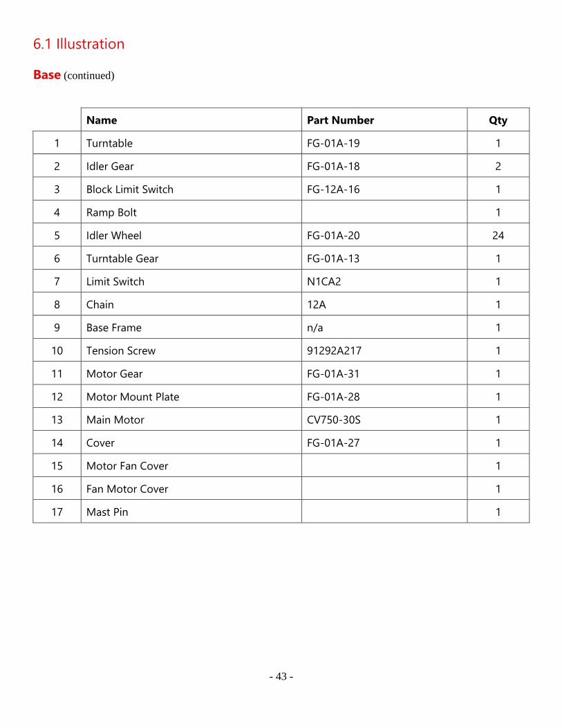
6.1 Illustration
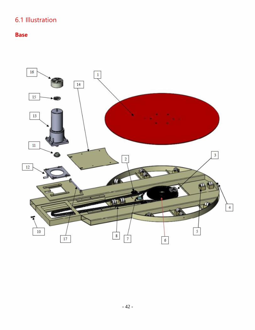
Base (continued)
Name Part Number Qty
1 Turntable FG-01A-19 1
2 Idler Gear FG-01A-18 2
3 Block Limit Switch FG-12A-16 1
4 Ramp Bolt 1
5 Idler Wheel FG-01A-20 24
6 Turntable Gear FG-01A-13 1
7 Limit Switch N1CA2 1
8 Chain 12A 1
9 Base Frame n/a 1
10 Tension Screw 91292A217 1
11 Motor Gear FG-01A-31 1
12 Motor Mount Plate FG-01A-28 1
13 Main Motor CV750-30S 1
14 Cover FG-01A-27 1
15 Motor Fan Cover 1
16 Fan Motor Cover 1
17 Mast Pin 1
- 44 -
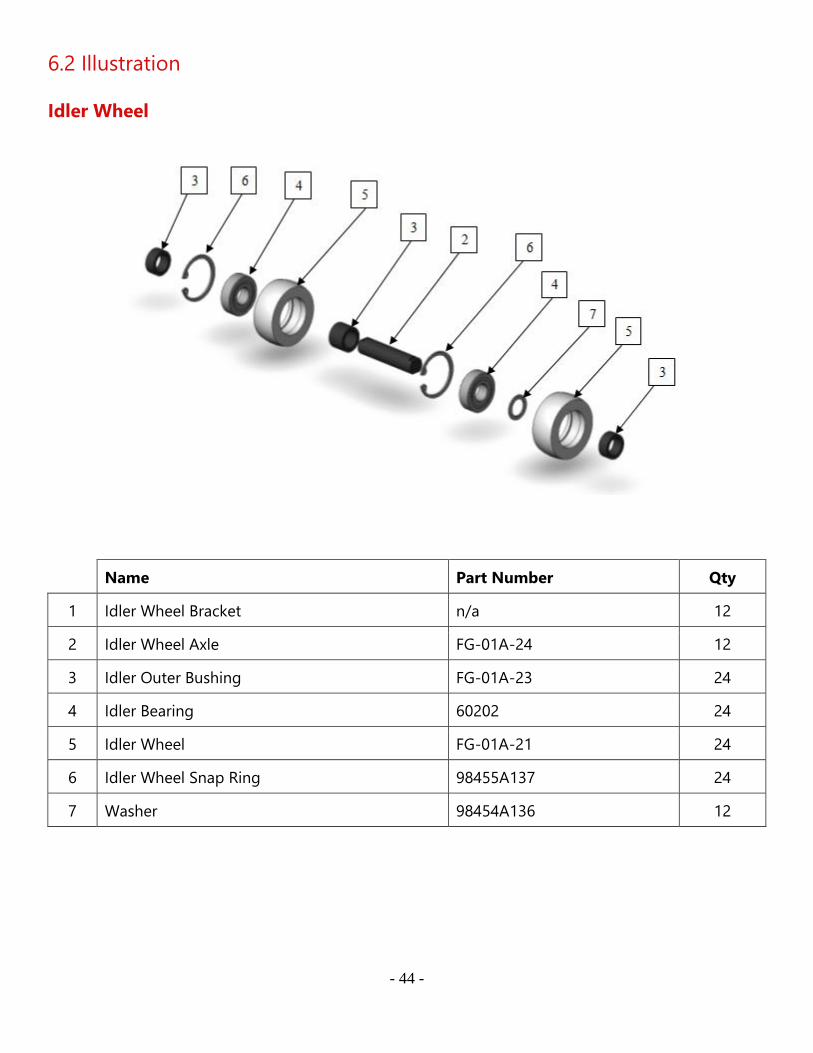
6.2 Illustration
Idler Wheel
Name Part Number Qty
1 Idler Wheel Bracket n/a 12
2 Idler Wheel Axle FG-01A-24 12
3 Idler Outer Bushing FG-01A-23 24
4 Idler Bearing 60202 24
5 Idler Wheel FG-01A-21 24
6 Idler Wheel Snap Ring 98455A137 24
7 Washer 98454A136 12

- 45 -
6.3 Illustration
Mast
- 46 -
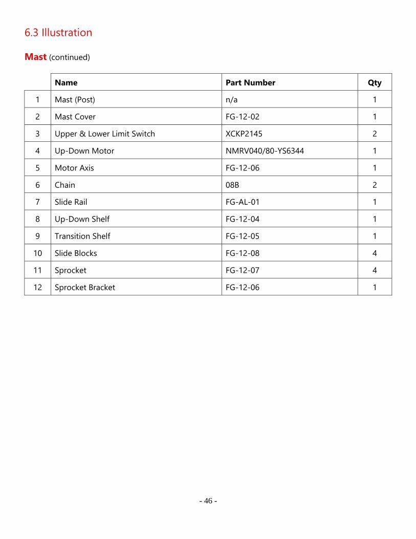
6.3 Illustration
Mast (continued)
Name Part Number Qty
1 Mast (Post) n/a 1
2 Mast Cover FG-12-02 1
3 Upper & Lower Limit Switch XCKP2145 2
4 Up-Down Motor NMRV040/80-YS6344 1
5 Motor Axis FG-12-06 1
6 Chain 08B 2
7 Slide Rail FG-AL-01 1
8 Up-Down Shelf FG-12-04 1
9 Transition Shelf FG-12-05 1
10 Slide Blocks FG-12-08 4
11 Sprocket FG-12-07 4
12 Sprocket Bracket FG-12-06 1
- 47 -
6.4 Illustration
Carriage
- 48 -
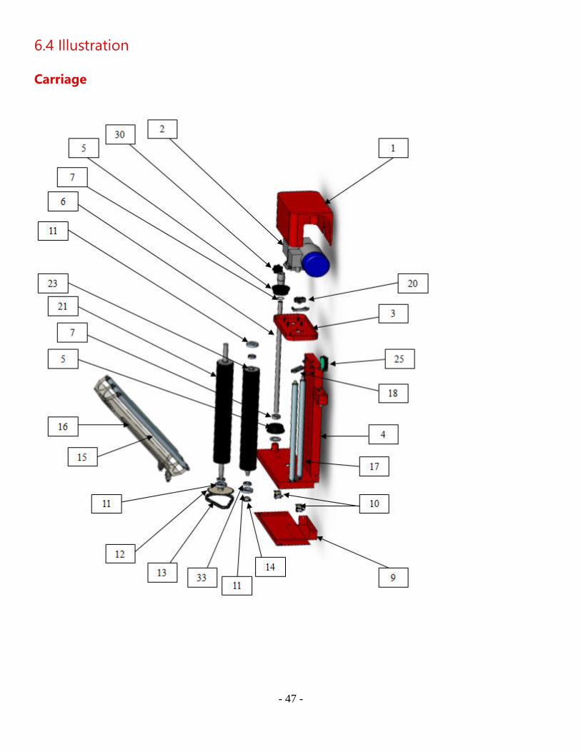
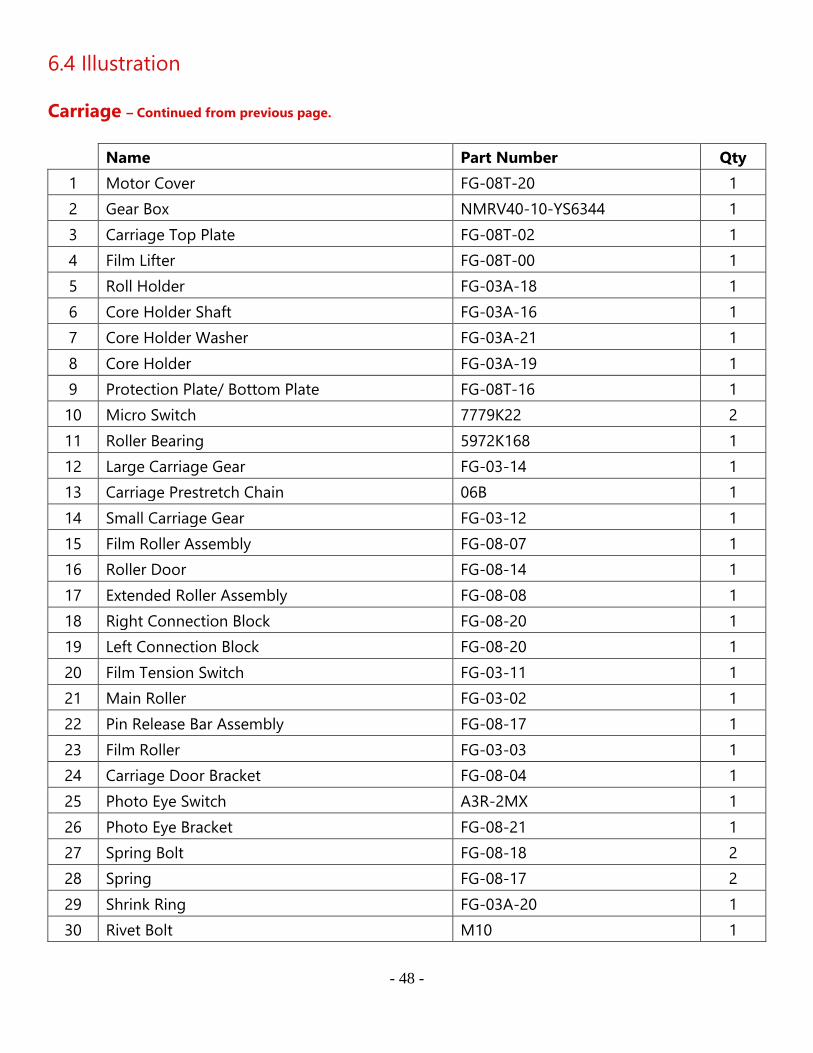
6.4 Illustration
Carriage – Continued from previous page.
Name Part Number Qty
1 Motor Cover FG-08T-20 1
2 Gear Box NMRV40-10-YS6344 1
3 Carriage Top Plate FG-08T-02 1
4 Film Lifter FG-08T-00 1
5 Roll Holder FG-03A-18 1
6 Core Holder Shaft FG-03A-16 1
7 Core Holder Washer FG-03A-21 1
8 Core Holder FG-03A-19 1
9 Protection Plate/ Bottom Plate FG-08T-16 1
10 Micro Switch 7779K22 2
11 Roller Bearing 5972K168 1
12 Large Carriage Gear FG-03-14 1
13 Carriage Prestretch Chain 06B 1
14 Small Carriage Gear FG-03-12 1
15 Film Roller Assembly FG-08-07 1
16 Roller Door FG-08-14 1
17 Extended Roller Assembly FG-08-08 1
18 Right Connection Block FG-08-20 1
19 Left Connection Block FG-08-20 1
20 Film Tension Switch FG-03-11 1
21 Main Roller FG-03-02 1
22 Pin Release Bar Assembly FG-08-17 1
23 Film Roller FG-03-03 1
24 Carriage Door Bracket FG-08-04 1
25 Photo Eye Switch A3R-2MX 1
26 Photo Eye Bracket FG-08-21 1
27 Spring Bolt FG-08-18 2
28 Spring FG-08-17 2
29 Shrink Ring FG-03A-20 1
30 Rivet Bolt M10 1
- 49 -
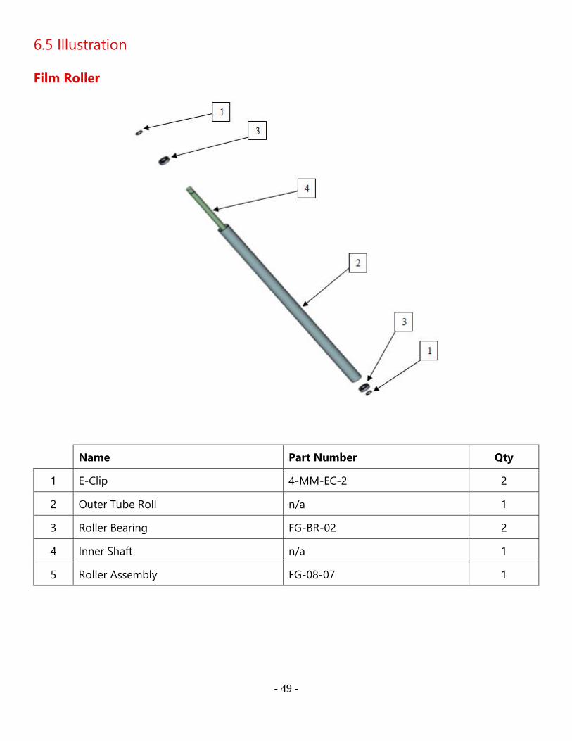
6.5 Illustration
Film Roller
Name Part Number Qty
1 E-Clip 4-MM-EC-2 2
2 Outer Tube Roll n/a 1
3 Roller Bearing FG-BR-02 2
4 Inner Shaft n/a 1
5 Roller Assembly FG-08-07 1
- 50 -
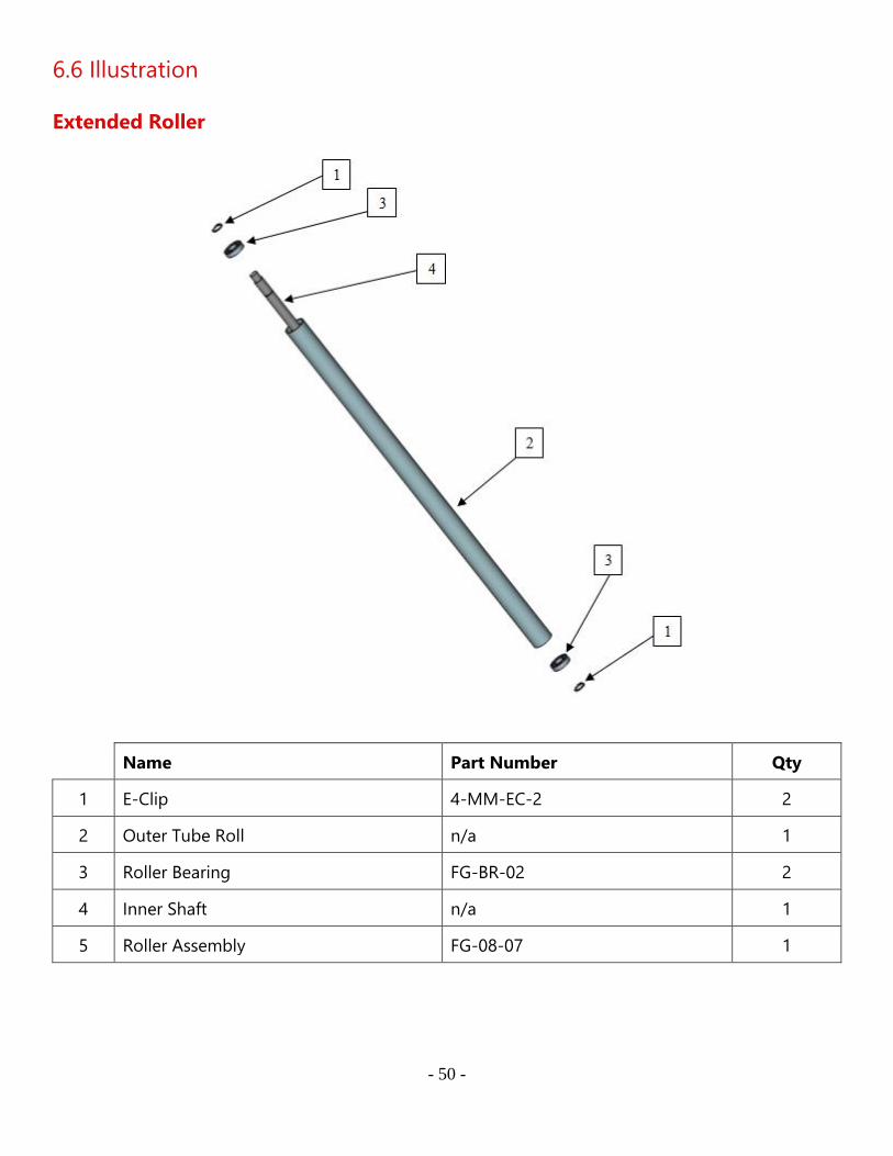
6.6 Illustration
Extended Roller
Name Part Number Qty
1 E-Clip 4-MM-EC-2 2
2 Outer Tube Roll n/a 1
3 Roller Bearing FG-BR-02 2
4 Inner Shaft n/a 1
5 Roller Assembly FG-08-07 1

- 51 -
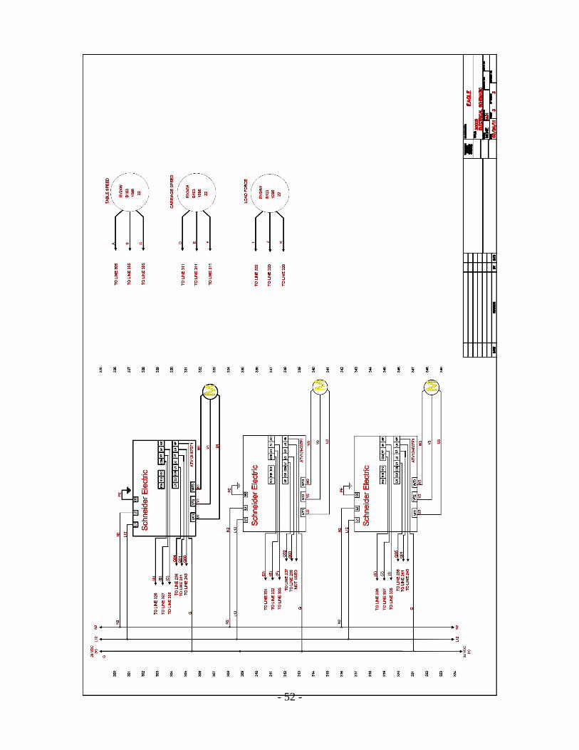
6.6 Motor Controls
- 52 -
- 53 -
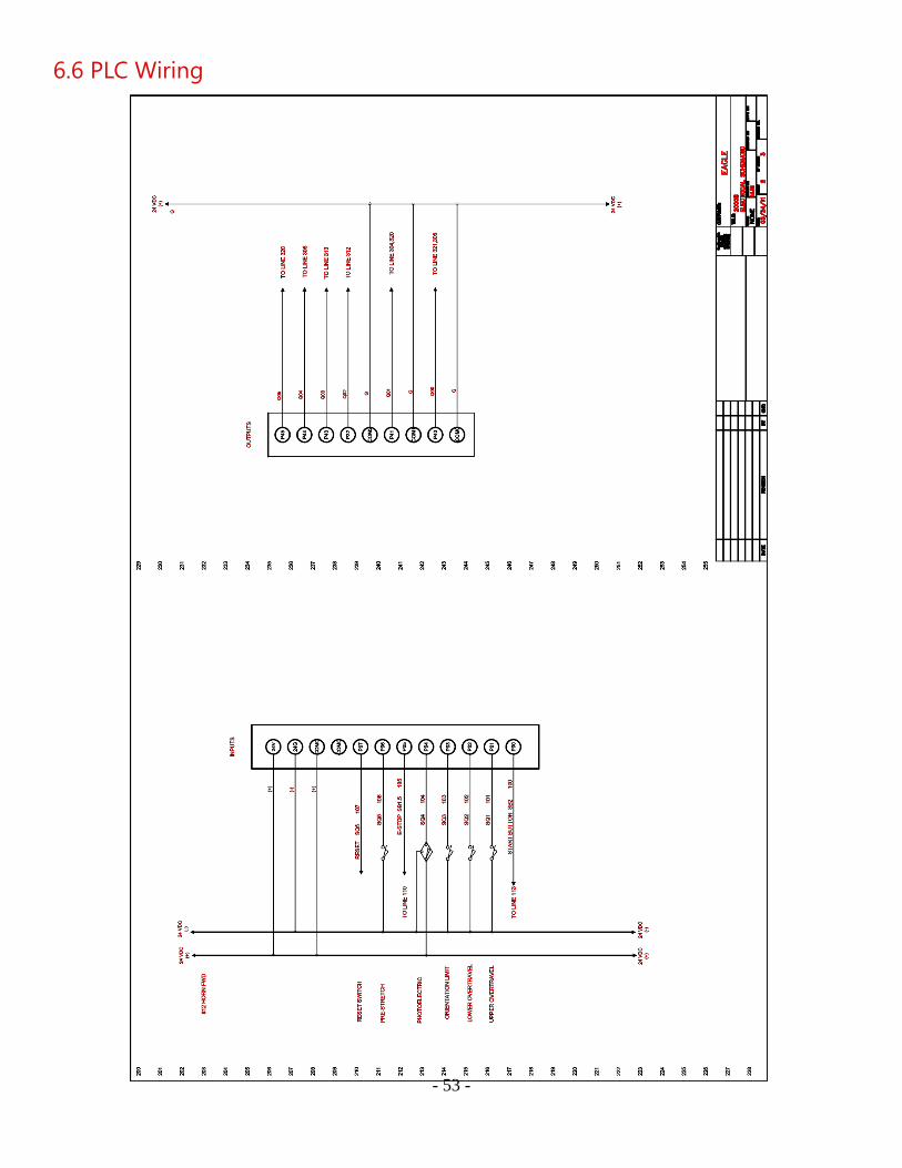
6.6 PLC Wiring
- 54 -
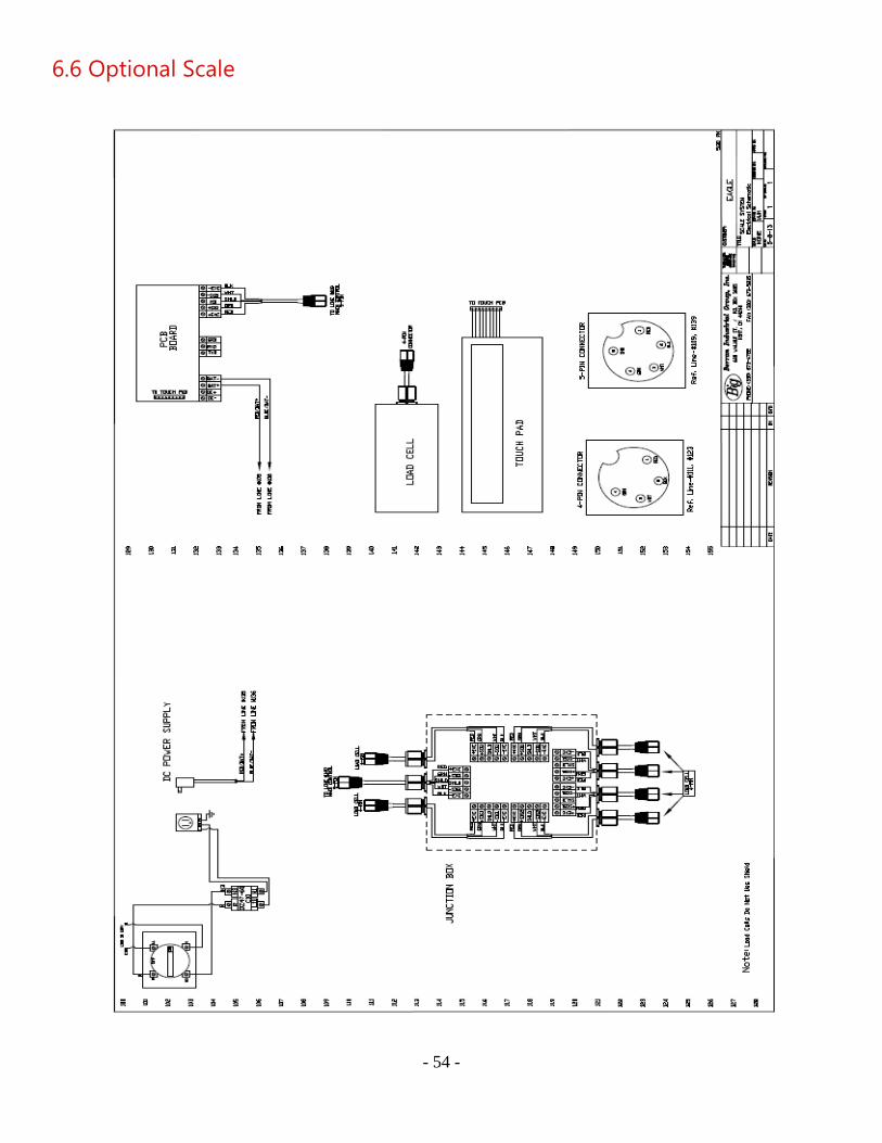
6.6 Optional Scale
- 55 -
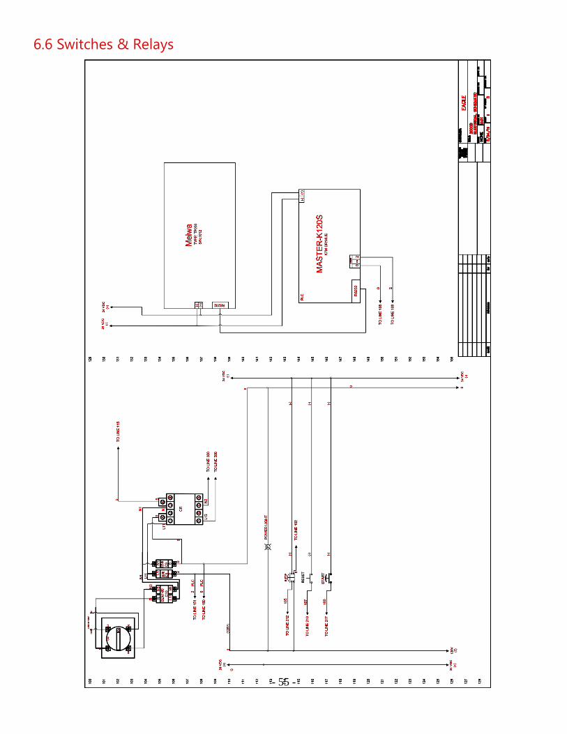
6.6 Switches & Relays