Embed Size (px)
Citation preview
Operations & Maintenance Manual
EXO BR MS Balanced RegulatorFull Face Mask
Military Standard
Kirby Morgan Dive Systems425 Garden Street
Santa Barbara, CA 93101United States of America
Telephone (805) 965-8538, FAX (805) 966-5761Email: [email protected]
Web Site: www.KirbyMorganDiveSystems.com
Manual prepared by: Kirby Morgan Dive SystemsEXO BR MS 26 is a registered trademark of Kirby Morgan Dive Systems
©2000 Kirby Morgan Dive Systems
Document #000417001
DSI Part #100-036
ii
EXO BR MS Full Face Mask Manual
Document #000417001
To Our Customers:
We feel it is important for the reader to understand that we consider ourselves only a part of the
process along the path in diving equipment design. We welcome all input from our customers. Many
diving equipment engineers, diving medical specialists, diving organization administrators and their
supporting personnel, along with thousands of divers, have contributed to the current state of the art
of diving. Each piece of gear we manufacture has in it some of the thinking of those who have gone
before us. To all those people who give something of themselves and to the men and women who
work underwater, we express a heartfelt thank you.
Providing the best diving equipment and service possible has always been and will always be the
policy of Kirby Morgan Dive Systems.
Steve KushnerPresident, Kirby Morgan Dive Systems
iii
EXO BR MS Full Face Mask Manual
Document #000417001
ChangeNo.
Date Description of Change PageNo.
Record of Changes
iv
EXO BR MS Full Face Mask Manual
Document #000417001
WARNING: Quest è un avviso importante. Tradurlo.
This EXO BR MS Full Face Mask is intended for use by trained divers who have successfullycompleted a recognized training course in the use of a Full Face Mask and, if used in thesurface-supplied mode, an approved surface-supplied diving course.
Important Safety Information
Read this manual before using or maintaining the mask, even if you have experience withother diving masks.
This manual is intended for military use. Technical information and procedures have beentailored for military use, and some specific details and procedures vary from those in ourstandard commercial EXO BR MS manual. Any questions regarding the use, maintenance, oroperation of this mask can be directed to Kirby Morgan Dive Lab, Panama City, Florida,telephone (850) 233-6680.
DANGER: Diving in an environment that is chemically, biologically, orradiologically contaminated is extremely hazardous. Although the EXO BR MSFull Face Mask may be adapted for use in some contaminated environments, specialtraining, equipment, and procedures, are necessary. Do not dive in a contami-nated environment unless you have been thoroughly trained and equipped forthis type of diving.
DANGER: Kirby Morgan Dive Systems warns all divers who use the EXOBR MS Full Face Mask to use only DSI original spare parts from a DSI autho-rized dealer. Other parts, O-rings and fittings may not be manufactured to the samestandards maintained by DSI. The use of any spares other than DSI originalparts may lead to equipment failure and accidents.
WARNING: Follow all the instructions in this manual carefully, and heed allsafety precautions. Improper use of this diving mask could result in seriousinjury or death.
v
EXO BR MS Full Face Mask Manual
Document #000417001
1.1 Introduction.................................................................................................................
1.2 Specifications.............................................................................................................
1.3 Design Purpose..........................................................................................................
1.4 Accessories.................................................................................................................
1.4.1 Hoods............................................................................................................... ...
1.4.2 Mask Carrying Bag..............................................................................................
1.4.3 Communications..................................................................................................
1.4.4 Low-Pressure High-Flow Hose............................................................................
1.4.5 Manifold Block.....................................................................................................
1.4.6 Tool Kit & Pouch...................................................................................................
1.4.7 Deluxe Tool Kit.....................................................................................................
1.4.8 Face Cushion Kit ...............................................................................................
1.4.9 EXO BR MS Reg Rebuild Kit..............................................................................
1.4.10 EXO BR MS Mask Spares Kit..............................................................................
1.4.11 EXO BR MS Hard Shell.......................................................................................
1.4.12 Air Inlet Swivel ....................................................................................................
1.4.13 Over-Pressure Relief Valve and First Stage Regulators.....................................
2.1 Introduction ...............................................................................................................
2.2 First Use.....................................................................................................................
2.3 Pre-Mission Maintenance..........................................................................................
2.4 Visual Inspection .......................................................................................................
2.5 Clean Face Port ......................................................................................................
2.6 Adjusting the Equalizer..............................................................................................
2.7 Checking Regulator Functions
and Preparing the EXO BR MS for Use in the SCUBA Mode ................................
2.8 Wireless Communications ........................................................................................
2.9 Checking Regulator Functions and
Preparing EXO BR MS for Surface-Supplied Mode Diving.....................................
2.10 Daily ..........................................................................................................................
2.11 Diver's Harness .........................................................................................................
2.12 Installing the Manifold Block on the Diver's Harness ................................................
2.13 Emergency Gas Supply (EGS).................................................................................
Chapter 2 Operating Instructions........................................................................... 7
1
2
2
3
3
4
4
4
4
4
4
5
5
5
5
5
5
7
7
7
7
7
8
8
9
10
11
11
11
11
ContentsChapter 1 General Information............................................................................... 1
vi
EXO BR MS Full Face Mask Manual
Document #000417001
5.1 General Information ..................................................................................................
5.2 Regulator Inlet Valve Maintenance
Without Removing the Complete Demand Regulator ..............................................
5.3 Inlet Valve Reassembly ............................................................................................
5.4 Complete Regulator Assembly Removal for Annual Overhaul .................................
5.4.1 Regulator Assembly Removal ............................................................................
5.4.2 Balanced Regulator Disassembly ......................................................................
5.4.3 Regulator Maintenance .....................................................................................
5.4.4 Regulator Reassembly ......................................................................................
5.4.5 Regulator Installation .........................................................................................
5.5 EXO BR MS Regulator Adjustment ..........................................................................
5.6 Lens Replacement ....................................................................................................
5.6.1 Lens Removal ....................................................................................................
5.6.2 Lens Installation .................................................................................................
5.7 Buckle Replacement ................................................................................................
4.1 Post-Dive Sanitizing...................................................................................................
4.2 Reassembling the Mask After Cleaning ....................................................................
Chapter 5 EXO BR MS Mask Maintenance..........................................................
3.1 Introduction ...............................................................................................................
3.2 Water Entry ...............................................................................................................
3.3 Regulator Adjustment ...............................................................................................
3.4 Spider Adjustment ....................................................................................................
3.5 Purging the Mask ......................................................................................................
3.6 Emergency Procedures for Surface-Supplied Use....................................................
Chapter 4 Post-Dive Procedures ............................................................................
Chapter 3 In-Water Operations ...............................................................................
2.14 First Stage Regulator and Over-Pressure Relief ......................................................
2.15 Connecting the Hoses to the Manifold Block ..........................................................
2.16 Hard Wire Communications ....................................................................................
2.17 Recommendations for Donning and Removing ......................................................
2.17.1 Donning ............................................................................................................
2.17.2 Mask Removal ..................................................................................................
2.18 Proper Hood Fit .......................................................................................................
19
19
19
23
24
24
25
25
26
28
29
30
30
31
33
17
17
17
11
12
12
12
12
14
14
15
15
15
15
15
16
16
vii
EXO BR MS Full Face Mask Manual
Document #000417001
5.7.1 Buckle Removal .................................................................................................
5.7.2 Buckle Installation ..............................................................................................
5.8Replacing the Face Seal or Frame ..........................................................................
5.8.1 Face Seal Removal ...........................................................................................
5.8.2 Face Seal Installation ........................................................................................
5.9 Manifold Block Maintenance ....................................................................................
5.9.1 Daily ...................................................................................................................
5.9.2 Post-Dive Procedures ........................................................................................
5.9.3 Annual Overhaul of the Manifold Block Assembly..............................................
5.9.3.1 Disassembly of the Manifold Block .........................................................
5.9.3.2 Disassembly and Cleaning of the One-Way Valve ..................................
5.9.3.3 Reassembly of the One-Way Valve .........................................................
5.9.3.4 Disassembly of the Auxiliary Valve .........................................................
5.9.3.5 Cleaning and Lubricating the Auxiliary Valve .........................................
5.9.3.6 Reassembly of the Auxiliary Valve ..........................................................
5.9.3.7 Reassembly of the Manifold Block Assembly...........................................
6.1 Waterproof Connector (WPC) ..................................................................................
6.2 Wireless Communications ........................................................................................
6.3 Removing the Communications Module ...................................................................
6.4 Installing the Communications Module .....................................................................
6.5 Earphone and/or Microphone Removal ....................................................................
6.6 Earphone and/or Microphone Installation .................................................................
6.7 Removing the Waterproof Connector (WPC) ...........................................................
6.8 Installing the Waterproof Connector (WPC) .............................................................
6.9 Waterproof Connector (WPC) Assembly Rebuild .....................................................
6.10 Waterproof Connector (WPC) Pin Diagrams ........................................................ ...
6.11 Post-Dive Maintenance ........................................................................................ ....
Appendix A Pre-Mission Inspection Checklist...................................................................
Appendix B Pre-Dive Setup Checklist...............................................................................
Appendix C Supervisor’s Equipment Checks
Prior to Water Entry in Surface-Supplied Diving............................................
Appendix D Post-Dive Checklist.......................................................................................
Appendix E Post-Mission Inspection and Checklist..........................................................
EXO BRMS Exploded views and parts lists.......................................................................
Chapter 6 Communications ......................................................................................
33
34
35
35
35
35
35
36
36
36
37
37
38
38
39
39
41
41
41
42
43
43
43
44
44
45
45
46
47
48
49
50
51
52
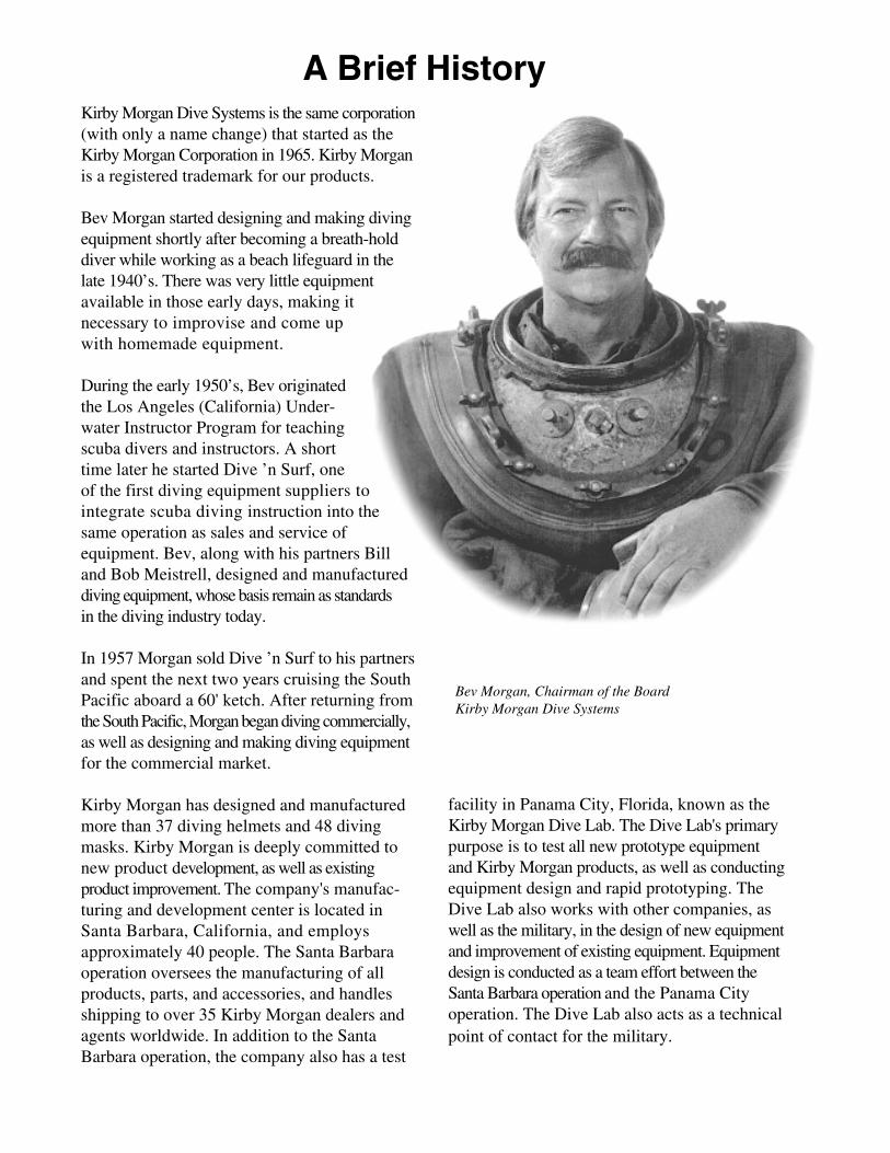
Bev Morgan, Chairman of the BoardKirby Morgan Dive Systems
A Brief HistoryKirby Morgan Dive Systems is the same corporation(with only a name change) that started as theKirby Morgan Corporation in 1965. Kirby Morganis a registered trademark for our products.
Bev Morgan started designing and making divingequipment shortly after becoming a breath-holddiver while working as a beach lifeguard in thelate 1940’s. There was very little equipmentavailable in those early days, making itnecessary to improvise and come upwith homemade equipment.
During the early 1950’s, Bev originatedthe Los Angeles (California) Under-water Instructor Program for teachingscuba divers and instructors. A shorttime later he started Dive ’n Surf, oneof the first diving equipment suppliers tointegrate scuba diving instruction into thesame operation as sales and service ofequipment. Bev, along with his partners Billand Bob Meistrell, designed and manufactureddiving equipment, whose basis remain as standardsin the diving industry today.
In 1957 Morgan sold Dive ’n Surf to his partnersand spent the next two years cruising the SouthPacific aboard a 60' ketch. After returning fromthe South Pacific, Morgan began diving commercially,as well as designing and making diving equipmentfor the commercial market.
Kirby Morgan has designed and manufacturedmore than 37 diving helmets and 48 divingmasks. Kirby Morgan is deeply committed tonew product development, as well as existingproduct improvement. The company's manufac-turing and development center is located inSanta Barbara, California, and employsapproximately 40 people. The Santa Barbaraoperation oversees the manufacturing of allproducts, parts, and accessories, and handlesshipping to over 35 Kirby Morgan dealers andagents worldwide. In addition to the SantaBarbara operation, the company also has a test
facility in Panama City, Florida, known as theKirby Morgan Dive Lab. The Dive Lab's primarypurpose is to test all new prototype equipmentand Kirby Morgan products, as well as conductingequipment design and rapid prototyping. TheDive Lab also works with other companies, aswell as the military, in the design of new equipmentand improvement of existing equipment. Equipmentdesign is conducted as a team effort between theSanta Barbara operation and the Panama Cityoperation. The Dive Lab also acts as a technicalpoint of contact for the military.
1
Chapter 1 EXO BR MS Full Face Mask Manual
Document #000417001
DIVING SYSTEMS INTN'L
SANTA BARBARA CA./U.S
.A.
TEMPERED
Chapter 1General Information
1.1 Introduction
Kirby Morgan Dive Systems has been designingand manufacturing commercial, military,scientific, and search & rescue diving equipmentfor over thirty years. Many of our products havebecome the standard of the industry due todesign, high quality, and outstanding service. TheEXO BR MS is part of this continuing tradition.
This manual is intended for military use only.Technical information and procedures have beentailored for military use, and some specificdetails and procedures vary from those in ourstandard commercial EXO BR MS manual.Questions regarding the use, maintenance, oroperation of this mask, or associated equipment,can be directed to Kirby Morgan Dive Lab,Panama City, Florida, telephone (850)-233-6680.
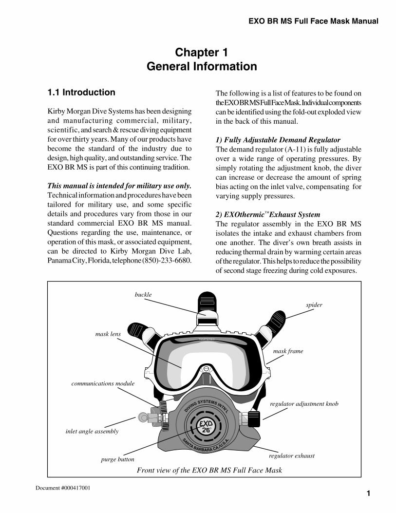
The following is a list of features to be found onthe EXO BR MS Full Face Mask. Individual componentscan be identified using the fold-out exploded viewin the back of this manual.
1) Fully Adjustable Demand RegulatorThe demand regulator (A-11) is fully adjustableover a wide range of operating pressures. Bysimply rotating the adjustment knob, the divercan increase or decrease the amount of springbias acting on the inlet valve, compensating forvarying supply pressures.
2) EXOthermic™Exhaust SystemThe regulator assembly in the EXO BR MSisolates the intake and exhaust chambers fromone another. The diver’s own breath assists inreducing thermal drain by warming certain areasof the regulator. This helps to reduce the possibilityof second stage freezing during cold exposures.
buckle
mask lens
purge button
spider
regulator adjustment knob
regulator exhaust
mask frame
communications module
Front view of the EXO BR MS Full Face Mask
inlet angle assembly
2
Chapter 1EXO BR MS Full Face Mask Manual
Document #000417001
3) Earphone PocketsThe earphones are allowed to equalize becauseall interior parts of the mask share a commoncavity. There is never a need to adjust theirposition, and they are easily accessible.
4) EXO BR MS Skeleton™
The outer frame, or EXO BR MS Skeleton,™
serves several functions. It protects the face sealand is used to mount external components suchas the regulator, lens, and communications. Theouter frame is made of Poly Carbonate plastic
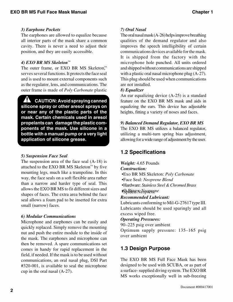
CAUTION: Avoid spraying cannedsilicone spray or other aresol sprays onor near any of the plastic parts of themask. Certain chemicals used in aresolpropelants can damage the plastic com-ponents of the mask. Use silicone in abottle with a manual pump or a very lightapplication of silicone grease.
5) Suspension Face SealThe suspension area of the face seal (A-18) isattached to the EXO BR MS Skeleton™ by fivemounting legs, much like a trampoline. In thisway, the face seals on a soft flexible area ratherthan a narrow and harder type of seal. Thisallows the EXO BR MS to fit different sizes andshapes of faces. The extra area behind the faceseal allows a foam pad to be inserted for extrasmall (narrow) faces.
6) Modular CommunicationsMicrophone and earphones can be easily andquickly replaced. Simply remove the mountingnut and push the entire module to the inside ofthe mask. The earphones and microphone canthen be removed. A spare communications setcomes in handy for rapid replacement in thefield, if needed. If the mask is to be used withoutcommunications, an oral nasal plug, DSI Part#320-001, is available to seal the microphonecup in the oral nasal (A-27).
7) Oral NasalThe oral nasal mask (A-26) helps improve breathingqualities of the demand regulator and alsoimproves the speech intelligibility of certaincommunications devices available for the mask.It is shipped from the factory with themicrophone hole punched. All units orderedand shipped without communications are shippedwith a plastic oral nasal microphone plug (A-27).This plug should be used when communicationsare not installed.8) EqualizerAn ear equalizing device (A-25) is a standardfeature on the EXO BR MS mask and aids inequalizing the ears. This device has adjustableheights, fitting a variety of noses and faces.
9) Balanced Demand Regulator, EXO BR MSThe EXO BR MS utilizes a balanced regulator,utilizing a multi-turn spring bias adjustment,allowing for a wide range of adjustment by the user.
1.2 Specifications
Weight: 4.65 PoundsConstruction: •Exo BR MS Skeleton: Poly Carbonate •Face Seal: Neoprene Blend •Hardware: Stainless Steel & Chromed Brass •O-Rings: Neoprene •Spider: NeopreneRecommended Lubricant:Lubricants conforming to Mil-G-27617 type III.Lubricants should be used sparingly and allexcess wiped free.Operating Pressures:90–225 psig over ambientOptimum supply pressure: 135–165 psigover ambient
1.3 Design Purpose
The EXO BR MS Full Face Mask has beendesigned to be used with SCUBA, or as part ofa surface- supplied diving system. The EXO BRMS works exceptionally well in sub-freezing
3
Chapter 1 EXO BR MS Full Face Mask Manual
Document #000417001
conditions. The diver-controlled biased adjust-ment allows the use of a wide range of supplypressures, allowing greater flexibility in adaptingto various surface-supported systems. The EXOBR MS is compatible with many commerciallyavailable through-water communications,making it ideal for commercial, scientific andsearch/rescue diving. The EXO BR MS line hasbecome very popular with many search andrescue teams, requiring the added safety andprotection of a full face mask.
EXO BR MS Pressure Requirements:The regulator on the EXO BR MS can be operatedwith air pressures as low as 90 psig o.b. to amaximum depth of 60 fsw when used with certifiedsurface-supplied systems unable to deliver higherpressures. For systems capable of supplying higherpressures, the following should be used:
0–130 fsw, use 135–165 psig o.b.
130–190 fsw, use 165–225 psig o.b.
For SCUBA, an intermediate pressure of135–165 is recommended.
1.4 Accessories
There are a number of authorized accessories forthe EXO BR MS Full Face Mask.
1.4.1 Hoods
Kirby Morgan Dive Systems manufactures a hoodperfectly tailored to the EXO BR MS masks. It hasthinner face seal material on the front, as opposedto the thicker material of normal types of hoods, forbetter comfort. Order DSI Part #310-030 Small,#310-031 Medium, #310-032 Large.
Cold Water (CW) versions are also available.These have a large “bib” that tucks into the diver'swetsuit. Order DSI Part #310-035 CW Small,#310-037 CW Medium, #310-039 CW Large.
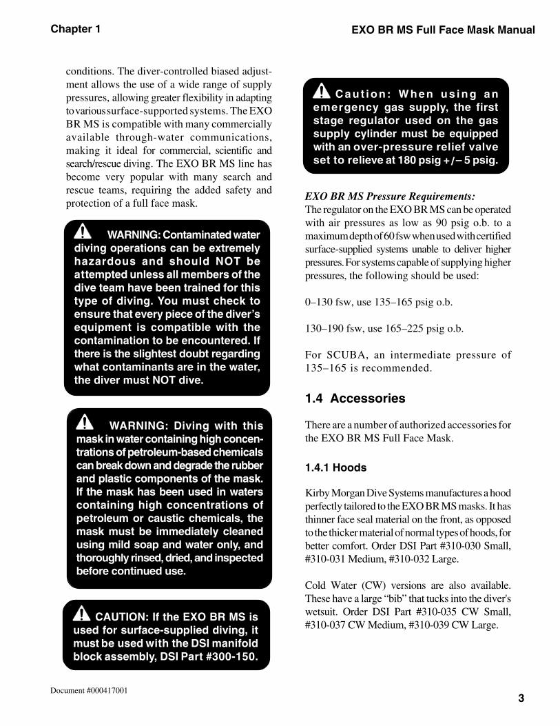
WARNING: Diving with thismask in water containing high concen-trations of petroleum-based chemicalscan break down and degrade the rubberand plastic components of the mask.If the mask has been used in waterscontaining high concentrations ofpetroleum or caustic chemicals, themask must be immediately cleanedusing mild soap and water only, andthoroughly rinsed, dried, and inspectedbefore continued use.
CAUTION: If the EXO BR MS isused for surface-supplied diving, itmust be used with the DSI manifoldblock assembly, DSI Part #300-150.
C a u t i o n : W h e n u s i n g a nemergency gas supply, the firststage regulator used on the gassupply cylinder must be equippedwith an over-pressure relief valveset to relieve at 180 psig + / – 5 psig.
WARNING: Contaminated waterdiving operations can be extremelyhazardous and should NOT beattempted unless all members of thedive team have been trained for thistype of diving. You must check toensure that every piece of the diver’sequipment is compatible with thecontamination to be encountered. Ifthere is the slightest doubt regardingwhat contaminants are in the water,the diver must NOT dive.
4
Chapter 1EXO BR MS Full Face Mask Manual
Document #000417001
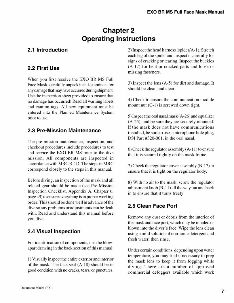
1.4.4 Low-Pressure High-Flow Hose
A low-pressure high-flow hose for the EXO BRMS is supplied as standard, and this hose shouldbe used when using the manifold block to ensurethe maximum flow of gas when umbilical diving.This hose attaches to the manifold block and hasa thread size of 1/2"–20 tpi. Order DSI Part #255-050.This hose may also be used on ANU (Authorizedfor Navy Use) SCUBA first stage regulators
having this thread size. For first stage regulatorsfrom the ANU list with 3/8"–24 tpi LP ports, thestandard bore hose may be used (DSI Part #355-026).
1.4.5 Manifold Block
When using the EXO BR MS for surface-supplieddiving, the use of the manifold block assemblyis mandatory. The manifold block is equippedwith a one-way valve andprovides for correctattachment to theumbilical and safetyharness. The auxiliaryvalve on the manifold blockalso controls the flow of thebailout supply. The manifoldblock is very similar to the side block assemblyof the MK 21 helmet and uses the same one-wayvalve and emergency supply valve. The 9/16"female umbilical fitting attaches to the one-wayvalve on the manifold block via a male 1/4" npt tomale 9/16" oxygen fitting. The standard Navyumbilical uses the 9/16" oxygen fitting. Themanifold block equipped with a 9/16" oxygenfitting is DSI Part #300-150.
1.4.6 Tool Kit & Pouch
A special tool kit and pouch is avail-able to store the back-up wrenchand regulator adjustment tool.DSI Part #325-630, Tool Kit & Pouch
1.4.7 Deluxe Tool Kit
This kit includes the regmount tool which is usedfor removing and replacingthe regulator assembly.This tool is required if anentire mask is to be
rebuilt, or a face seal replacement is to be done. DSI Part #325-650, Deluxe Tool Kit
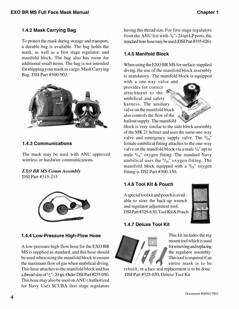
1.4.2 Mask Carrying Bag
To protect the mask during storage and transport,a durable bag is available. The bag holds themask, as well as a first stage regulator, andmanifold block. The bag also has room foradditional small items. The bag is not intendedfor shipping your mask as cargo. Mask CarryingBag, DSI Part #300-902.
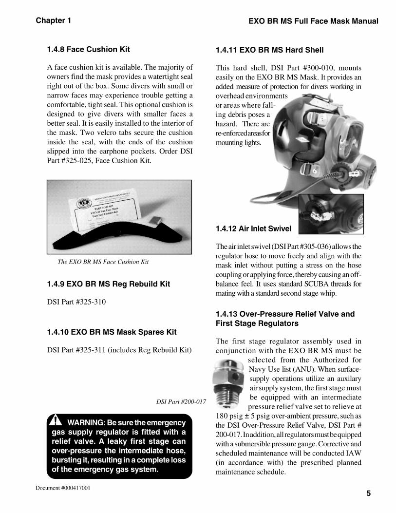
1.4.3 Communications
The mask may be used with ANU approvedwireless or hardwire communications.
EXO BR MS Comm AssemblyDSI Part #315-215
5
Chapter 1 EXO BR MS Full Face Mask Manual
Document #000417001
DSI Part #200-017
The EXO BR MS Face Cushion Kit
1.4.11 EXO BR MS Hard Shell
This hard shell, DSI Part #300-010, mountseasily on the EXO BR MS Mask. It provides anadded measure of protection for divers working inoverhead environmentsor areas where fall-ing debris poses ahazard. There arere-enforced areas formounting lights.
1.4.12 Air Inlet Swivel
The air inlet swivel (DSI Part #305-036) allows theregulator hose to move freely and align with themask inlet without putting a stress on the hosecoupling or applying force, thereby causing an off-balance feel. It uses standard SCUBA threads formating with a standard second stage whip.
1.4.13 Over-Pressure Relief Valve andFirst Stage Regulators
The first stage regulator assembly used inconjunction with the EXO BR MS must be
selected from the Authorized forNavy Use list (ANU). When surface-supply operations utilize an auxilaryair supply system, the first stage mustbe equipped with an intermediatepressure relief valve set to relieve at
180 psig ± 5 psig over-ambient pressure, such asthe DSI Over-Pressure Relief Valve, DSI Part #200-017. In addition, all regulators must be quippedwith a submersible pressure gauge. Corrective andscheduled maintenance will be conducted IAW(in accordance with) the prescribed plannedmaintenance schedule.
WARNING: Be sure the emergencygas supply regulator is fitted with arelief valve. A leaky first stage canover-pressure the intermediate hose,bursting it, resulting in a completeloss of the emergency gas system.
WARNING: Be sure the emergencygas supply regulator is fitted with arelief valve. A leaky first stage canover-pressure the intermediate hose,bursting it, resulting in a complete lossof the emergency gas system.
1.4.8 Face Cushion Kit
A face cushion kit is available. The majority ofowners find the mask provides a watertight sealright out of the box. Some divers with small ornarrow faces may experience trouble getting acomfortable, tight seal. This optional cushion isdesigned to give divers with smaller faces abetter seal. It is easily installed to the interior ofthe mask. Two velcro tabs secure the cushioninside the seal, with the ends of the cushionslipped into the earphone pockets. Order DSIPart #325-025, Face Cushion Kit.
1.4.9 EXO BR MS Reg Rebuild Kit
DSI Part #325-310
1.4.10 EXO BR MS Mask Spares Kit
DSI Part #325-311 (includes Reg Rebuild Kit)

6
Chapter 1EXO BR MS Full Face Mask Manual
Document #000417001
Notes
Chapter 2 EXO BR MS Full Face Mask Manual
7Document #000417001
2.1 Introduction
2.2 First Use
When you first receive the EXO BR MS FullFace Mask, carefully unpack it and examine it forany damage that may have occurred during shipment.Use the inspection sheet provided to ensure thatno damage has occurred! Read all warning labelsand caution tags. All new equipment must beentered into the Planned Maintenance Systemprior to use.
2.3 Pre-Mission Maintenance
The pre-mission maintenance, inspection, andcheckout procedures include procedures to testand service the EXO BR MS prior to the divemission. All components are inspected inaccordance with MRC R-1D. The steps in MRCcorrespond closely to the steps in this manual.
Before diving, an inspection of the mask and allrelated gear should be made (see Pre-MissionInspection Checklist, Appendix A, Chapter 6,page 49) to ensure everything is in proper workingorder. This should be done well in advance of thedive so any problems or adjustments can be dealtwith. Read and understand this manual beforeyou dive.
2.4 Visual Inspection
For identification of components, use the blow-apart drawing in the back section of this manual.
1) Visually inspect the entire exterior and interiorof the mask. The face seal (A-18) should be ingood condition with no cracks, tears, or punctures.
2) Inspect the head harness (spider/A-1). Stretcheach leg of the spider and inspect it carefully forsigns of cracking or tearing. Inspect the buckles(A-17) for bent or cracked parts and loose ormissing fasteners.
3) Inspect the lens (A-5) for dirt and damage. Itshould be clean and clear.
4) Check to ensure the communication modulemount nut (C-1) is screwed down tight.
5) Inspect the oral nasal mask (A-26) and equalizer(A-25), and be sure they are securely mounted.If the mask does not have communicationsinstalled, be sure to use a microphone hole plug,DSI Part #320-001, in the oral nasal.
6) Check the regulator assembly (A-11) to ensurethat it is secured tightly on the mask frame.
7) Check the regulator cover assembly (B-17) toensure that it is tight on the regulator body.
8) With no air to the mask, screw the regulatoradjustment knob (B-11) all the way out and backin to ensure that it turns freely.
2.5 Clean Face Port
Remove any dust or debris from the interior ofthe mask and face port, which may be inhaled orblown into the diver’s face. Wipe the lens cleanusing a mild solution of non-ionic detergent andfresh water, then rinse.
Under certain conditions, depending upon watertemperature, you may find it necessary to prepthe mask lens to keep it from fogging whilediving. There are a number of approvedcommercial defoggers available which work
Chapter 2Operating Instructions
EXO BR MS Full Face Mask Manual Chapter 2
8Document #000417001
knob (B-11) is screwed all the way in. This willprevent the regulator from free-flowing whenthe air is turned on.
Attach the first stage regulator to the SCUBAcylinder, and slowly open the gas supply valve,while holding the submersible pressure gaugeaway from you. Once the valve is open, checkthe pressure gauge to ensure adequate gas supply.
1) Check the demand regulator (A-11) for properadjustment and function. Make sure the demandregulator cover is fully screwed down.
2) Ensure the first stage regulator being usedhas an intermediate pressure setting ofbetween 135–165 psig.
3) Starting with the regulator adjustment knob(B-11) screwed all the way in, slowly back outthe regulator adjustment knob three full turns.
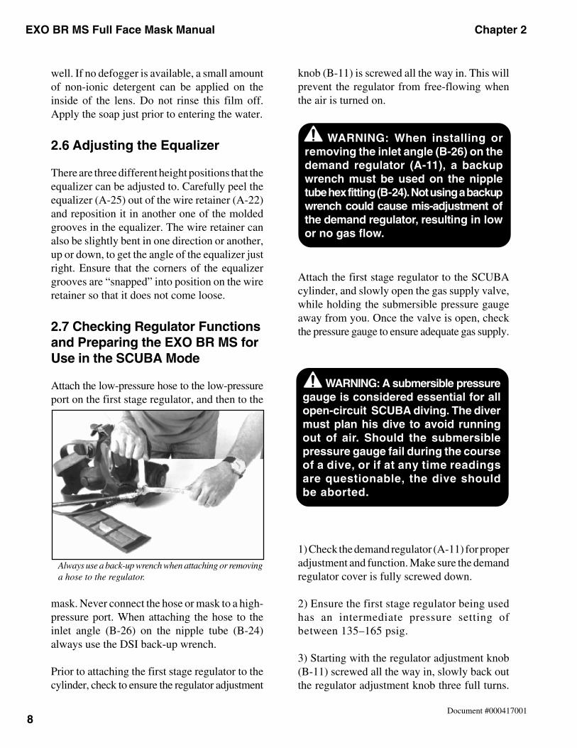
Always use a back-up wrench when attaching or removinga hose to the regulator.
well. If no defogger is available, a small amountof non-ionic detergent can be applied on theinside of the lens. Do not rinse this film off.Apply the soap just prior to entering the water.
2.6 Adjusting the Equalizer
There are three different height positions that theequalizer can be adjusted to. Carefully peel theequalizer (A-25) out of the wire retainer (A-22)and reposition it in another one of the moldedgrooves in the equalizer. The wire retainer canalso be slightly bent in one direction or another,up or down, to get the angle of the equalizer justright. Ensure that the corners of the equalizergrooves are “snapped” into position on the wireretainer so that it does not come loose.
2.7 Checking Regulator Functionsand Preparing the EXO BR MS forUse in the SCUBA Mode
Attach the low-pressure hose to the low-pressureport on the first stage regulator, and then to the
mask. Never connect the hose or mask to a high-pressure port. When attaching the hose to theinlet angle (B-26) on the nipple tube (B-24)always use the DSI back-up wrench.
Prior to attaching the first stage regulator to thecylinder, check to ensure the regulator adjustment
WARNING: When installing orremoving the inlet angle (B-26) on thedemand regulator (A-11), a backupwrench must be used on the nippletube hex fitting (B-24). Not using a backupwrench could cause mis-adjustment ofthe demand regulator, resulting in lowor no gas flow.
WARNING: A submersible pressuregauge is considered essential for allopen-circuit SCUBA diving. The divermust plan his dive to avoid runningout of air. Should the submersiblepressure gauge fail during the courseof a dive, or if at any time readingsare questionable, the dive shouldbe aborted.
Chapter 2 EXO BR MS Full Face Mask Manual
9Document #000417001
5) Loosen all the straps on the spider (A-1) andhold the mask on your face. Take a couple of goodbreaths, breathing slow and easy at first, then hardand fast. The regulator should be operating withthe minimal amount of breathing resistance andno free-flowing. With the mask on your face,slowly back out counterclockwise on the adjust-ment knob (B-11) until a slight free-flow develops,and then rotate the knob in clockwise approximatelytwo turns. Depress the purge button. Pressing thepurge button should cause a fairly strong gas flowinto the mask. If there is little or no flow whenpressing the purge button, or if breathing is difficult,see the Regulator Adjustment section in Chapter 5.
Once you enter the water, the regulator can befine tuned by turning the adjustment knob in orout. The adjustment knob (B-11) should be set atthe lightest setting possible that does not result ina free-flow condition.
2.8 Wireless Communications
Several ANU-approved wireless communi-cations units can be used with the EXO BR MSMask. If you are using wireless communications,read and follow all manufacturers instructionsfor your particular unit.
If you are using wireless communications, youshould test the communications by placing thetransducers from both send and receive units in
There should be no indication of gas flow. If gasis flowing, proceed to the regulator adjustmentsection in Chapter 5 to reset the regulator.
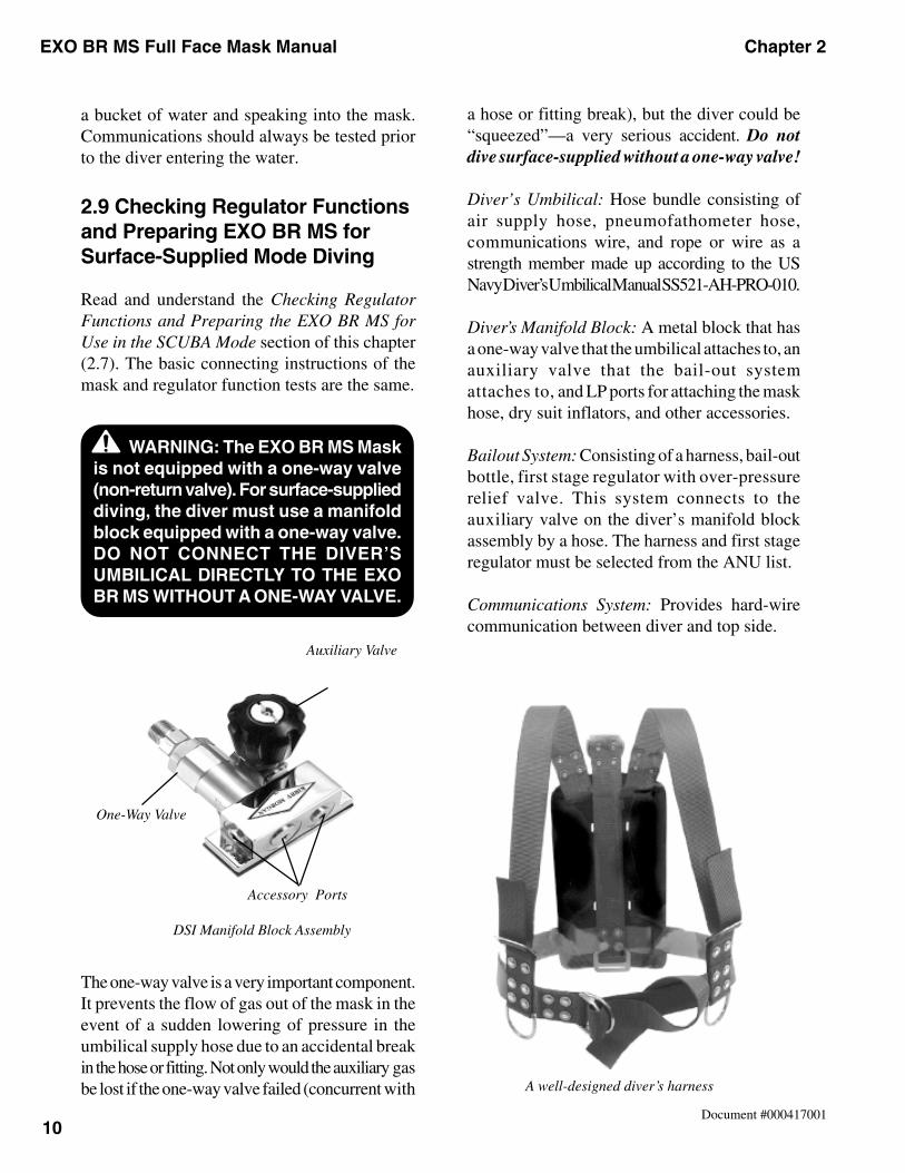
4) Using the spanner from the DSI tool kit, lay itacross the regulator cover (B-17 ) and press the
purge button as shown. A light flow of air shouldresult. Air should start flowing when the purgebutton has been depressed approximately 1/16" to1/8". If a flow of air cannot be detected, adjustmentwill be required. Refer to Chapter 5 for adjustment.
Use the spanner wrench to depress the purge buttonwhile turning the nipple to adjust the regulator.
WARNING: If diving SCUBA, thewaterproof case for your wirelesscommunications unit should be attachedonly to your SCUBA backpack, NEVERto your weight belt. In the event yourbelt must be dropped, the belt musthave a clear drop path and must notbe connected to any other piece ofgear. If this procedure is not followed,the weight belt and wireless electronicscase will be attached to the mask bythe connecting wire.
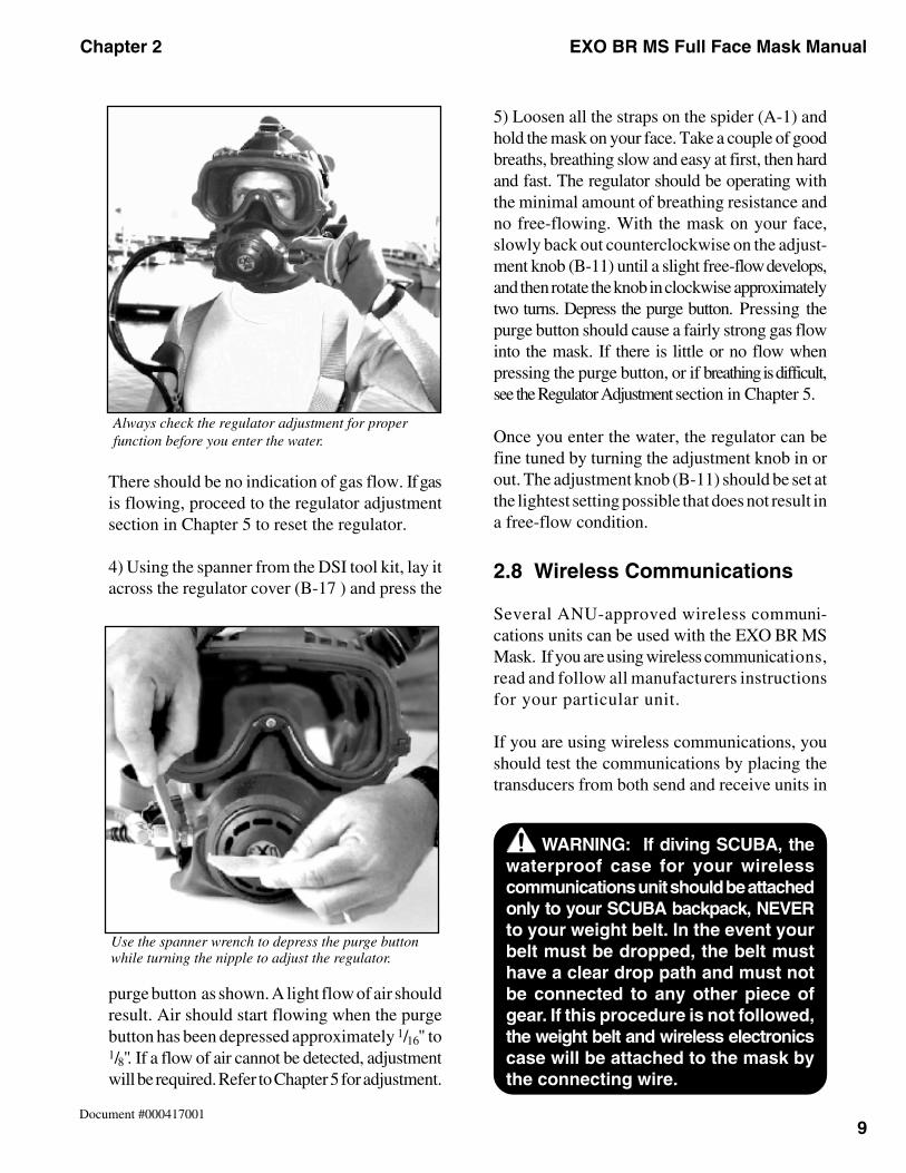
Always check the regulator adjustment for properfunction before you enter the water.
EXO BR MS Full Face Mask Manual Chapter 2
10Document #000417001
a bucket of water and speaking into the mask.Communications should always be tested priorto the diver entering the water.
2.9 Checking Regulator Functionsand Preparing EXO BR MS forSurface-Supplied Mode Diving
Read and understand the Checking RegulatorFunctions and Preparing the EXO BR MS forUse in the SCUBA Mode section of this chapter(2.7). The basic connecting instructions of themask and regulator function tests are the same.
The one-way valve is a very important component.It prevents the flow of gas out of the mask in theevent of a sudden lowering of pressure in theumbilical supply hose due to an accidental breakin the hose or fitting. Not only would the auxiliary gasbe lost if the one-way valve failed (concurrent with
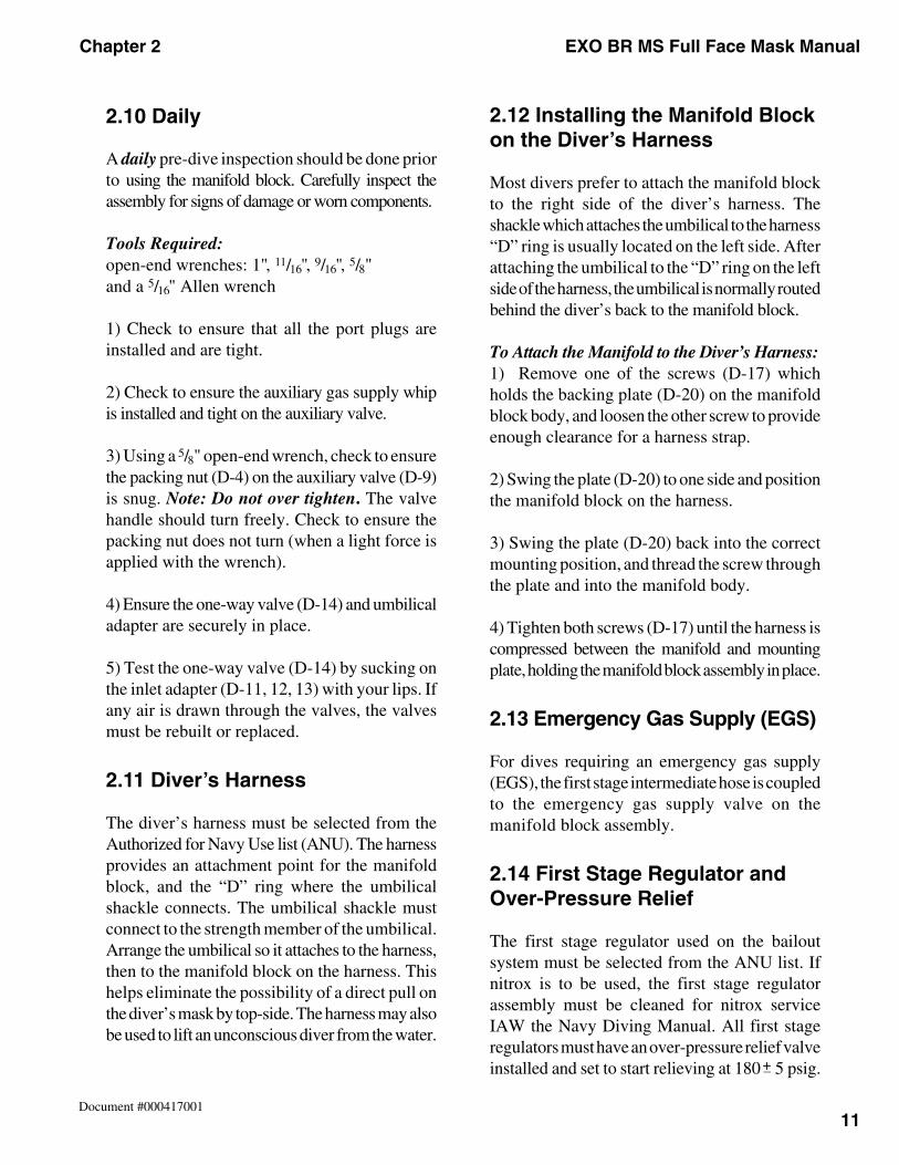
DSI Manifold Block Assembly
Auxiliary Valve
One-Way Valve
Accessory Ports
A well-designed diver’s harness
a hose or fitting break), but the diver could be“squeezed”—a very serious accident. Do notdive surface-supplied without a one-way valve!
Diver’s Umbilical: Hose bundle consisting ofair supply hose, pneumofathometer hose,communications wire, and rope or wire as astrength member made up according to the USNavy Diver’s Umbilical Manual SS521-AH-PRO-010.
Diver’s Manifold Block: A metal block that hasa one-way valve that the umbilical attaches to, anauxiliary valve that the bail-out systemattaches to, and LP ports for attaching the maskhose, dry suit inflators, and other accessories.
Bailout System: Consisting of a harness, bail-outbottle, first stage regulator with over-pressurerelief valve. This system connects to theauxiliary valve on the diver’s manifold blockassembly by a hose. The harness and first stageregulator must be selected from the ANU list.
Communications System: Provides hard-wirecommunication between diver and top side.
WARNING: The EXO BR MS Maskis not equipped with a one-way valve(non-return valve). For surface-supplieddiving, the diver must use a manifoldblock equipped with a one-way valve.DO NOT CONNECT THE DIVER’SUMBILICAL DIRECTLY TO THE EXOBR MS WITHOUT A ONE-WAY VALVE.
Chapter 2 EXO BR MS Full Face Mask Manual
11Document #000417001
2.10 Daily
A daily pre-dive inspection should be done priorto using the manifold block. Carefully inspect theassembly for signs of damage or worn components.
Tools Required:open-end wrenches: 1", 11/16", 9/16", 5/8"and a 5/16" Allen wrench
1) Check to ensure that all the port plugs areinstalled and are tight.
2) Check to ensure the auxiliary gas supply whipis installed and tight on the auxiliary valve.
3) Using a 5/8" open-end wrench, check to ensurethe packing nut (D-4) on the auxiliary valve (D-9)is snug. Note: Do not over tighten. The valvehandle should turn freely. Check to ensure thepacking nut does not turn (when a light force isapplied with the wrench).
4) Ensure the one-way valve (D-14) and umbilicaladapter are securely in place.
5) Test the one-way valve (D-14) by sucking onthe inlet adapter (D-11, 12, 13) with your lips. Ifany air is drawn through the valves, the valvesmust be rebuilt or replaced.
2.11 Diver’s Harness
The diver’s harness must be selected from theAuthorized for Navy Use list (ANU). The harnessprovides an attachment point for the manifoldblock, and the “D” ring where the umbilicalshackle connects. The umbilical shackle mustconnect to the strength member of the umbilical.Arrange the umbilical so it attaches to the harness,then to the manifold block on the harness. Thishelps eliminate the possibility of a direct pull onthe diver’s mask by top-side. The harness may alsobe used to lift an unconscious diver from the water.
2.12 Installing the Manifold Blockon the Diver’s Harness
Most divers prefer to attach the manifold blockto the right side of the diver’s harness. Theshackle which attaches the umbilical to the harness“D” ring is usually located on the left side. Afterattaching the umbilical to the “D” ring on the leftside of the harness, the umbilical is normally routedbehind the diver’s back to the manifold block.
To Attach the Manifold to the Diver’s Harness:1) Remove one of the screws (D-17) whichholds the backing plate (D-20) on the manifoldblock body, and loosen the other screw to provideenough clearance for a harness strap.
2) Swing the plate (D-20) to one side and positionthe manifold block on the harness.
3) Swing the plate (D-20) back into the correctmounting position, and thread the screw throughthe plate and into the manifold body.
4) Tighten both screws (D-17) until the harness iscompressed between the manifold and mountingplate, holding the manifold block assembly in place.
2.13 Emergency Gas Supply (EGS)
For dives requiring an emergency gas supply(EGS), the first stage intermediate hose is coupledto the emergency gas supply valve on themanifold block assembly.
2.14 First Stage Regulator andOver-Pressure Relief
The first stage regulator used on the bailoutsystem must be selected from the ANU list. Ifnitrox is to be used, the first stage regulatorassembly must be cleaned for nitrox serviceIAW the Navy Diving Manual. All first stageregulators must have an over-pressure relief valveinstalled and set to start relieving at 180 5 psig.+–
EXO BR MS Full Face Mask Manual Chapter 2
12Document #000417001
The purpose of this valve is to allow excesspressure to bleed off in the event the first stageregulator develops an internal leak. Without thisrelief valve present, the emergency supply hosefrom the first stage to the manifold block wouldrupture, resulting in a complete loss of the EGSsystem. Over-Pressure Relief Valve DSI Part #200-017.
2.15 Connecting the Hoses to theManifold Block
The manifold block has three low-pressure portswhich will accept a standard U.S. regulator hosewith a thread size 3/8"–24, and one port in linewith the one-way valve, which will accept a low-pressure, high-flow hose using thread size 1/2"–20.
CAUTION: The f i rst stageregulator must be equipped withan over-pressure relief valve whenusing the EXO BR MS.
1) Attach the first stage regulator to the bailoutcylinder, but do not open the valve.
2) Screw the hose from the first stage onto theauxiliary valve on the manifold block assembly.Tighten this fitting.
3) The diver’s umbilical should already beconnected to the topside dive control system atthis time. Remove the protective cap from thediver’s end of the umbilical. While pointing theopen end of the diver’s umbilical in a safedirection, slowly bring up air pressure on thedive control station regulator to around 20–30psig. This action will blow out any water, dust,or other foreign debris which may have enteredthe dive hose. Allow the air to vent from the hosefor at least 15 seconds.
4) Connect the diver’s air supply hose on theumbilical to the one-way valve on the diver’smanifold block assembly. Use the correct sizewrenches and always use a back-up wrench.Tighten the fitting until snug only. Do not overtighten. If too much force is applied to the fitting,it will cause the fitting to deform and leak.
5) Connect the hose, which was supplied withthe mask or the low-pressure high-flow hose, tothe appropriate low-pressure port on themanifold block, then to the mask. Remember toalways use a back-up wrench on the nipple tubewhen attaching the hose to the regulator on the mask.
2.16 Hard Wire Communications
There are several types of hard wire communicationsthat fit the EXO BR MS. DSI makes communicationsmodules with bare wire binding posts and moduleswith waterproof connectors. The communicationscomponents used with the EXO BR MS must beselected from the ANU list. The communicationssystem should always be checked prior to theactual dressing out of the divers. See Chapter 6for information on communications installation,testing, and maintenance.
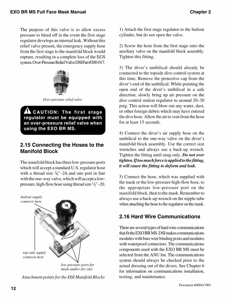
Over-pressure relief valve
bailout supplyconnects here
top-side supplyconnects here
low pressure ports formask and/or dry suit
Attachment points for the DSI Manifold Blocks
Chapter 2 EXO BR MS Full Face Mask Manual
13Document #000417001
2) Be sure all five legs of the spider are loosenedall the way.
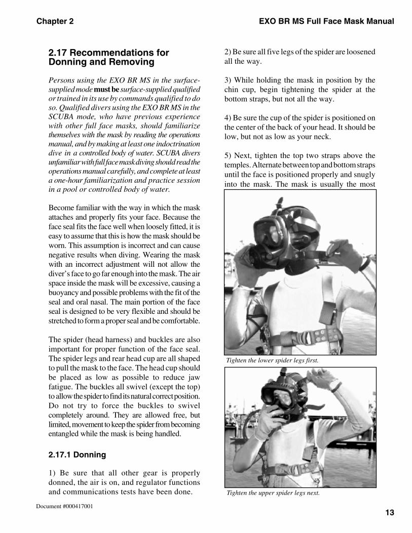
3) While holding the mask in position by thechin cup, begin tightening the spider at thebottom straps, but not all the way.
4) Be sure the cup of the spider is positioned onthe center of the back of your head. It should below, but not as low as your neck.
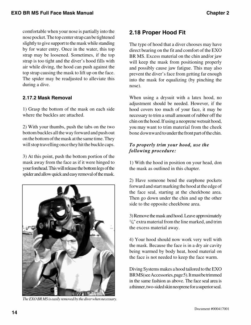
5) Next, tighten the top two straps above thetemples. Alternate between top and bottom strapsuntil the face is positioned properly and snuglyinto the mask. The mask is usually the most
2.17 Recommendations forDonning and Removing
Persons using the EXO BR MS in the surface-supplied mode must be surface-supplied qualifiedor trained in its use by commands qualified to doso. Qualified divers using the EXO BR MS in theSCUBA mode, who have previous experiencewith other full face masks, should familiarizethemselves with the mask by reading the operationsmanual, and by making at least one indoctrinationdive in a controlled body of water. SCUBA diversunfamiliar with full face mask diving should read theoperations manual carefully, and complete at leasta one-hour familiarization and practice sessionin a pool or controlled body of water.
Become familiar with the way in which the maskattaches and properly fits your face. Because theface seal fits the face well when loosely fitted, it iseasy to assume that this is how the mask should beworn. This assumption is incorrect and can causenegative results when diving. Wearing the maskwith an incorrect adjustment will not allow thediver’s face to go far enough into the mask. The airspace inside the mask will be excessive, causing abuoyancy and possible problems with the fit of theseal and oral nasal. The main portion of the faceseal is designed to be very flexible and should bestretched to form a proper seal and be comfortable.
The spider (head harness) and buckles are alsoimportant for proper function of the face seal.The spider legs and rear head cup are all shapedto pull the mask to the face. The head cup shouldbe placed as low as possible to reduce jawfatigue. The buckles all swivel (except the top)to allow the spider to find its natural correct position.Do not try to force the buckles to swivelcompletely around. They are allowed free, butlimited, movement to keep the spider from becomingentangled while the mask is being handled.
2.17.1 Donning
1) Be sure that all other gear is properlydonned, the air is on, and regulator functionsand communications tests have been done. Tighten the upper spider legs next.
Tighten the lower spider legs first.
EXO BR MS Full Face Mask Manual Chapter 2
14Document #000417001
comfortable when your nose is partially into thenose pocket. The top center strap can be tightenedslightly to give support to the mask while standingby for water entry. Once in the water, this topstrap may be loosened. Sometimes, if the topstrap is too tight and the diver’s hood fills withair while diving, the hood can push against thetop strap causing the mask to lift up on the face.The spider may be readjusted to alleviate thisduring a dive.
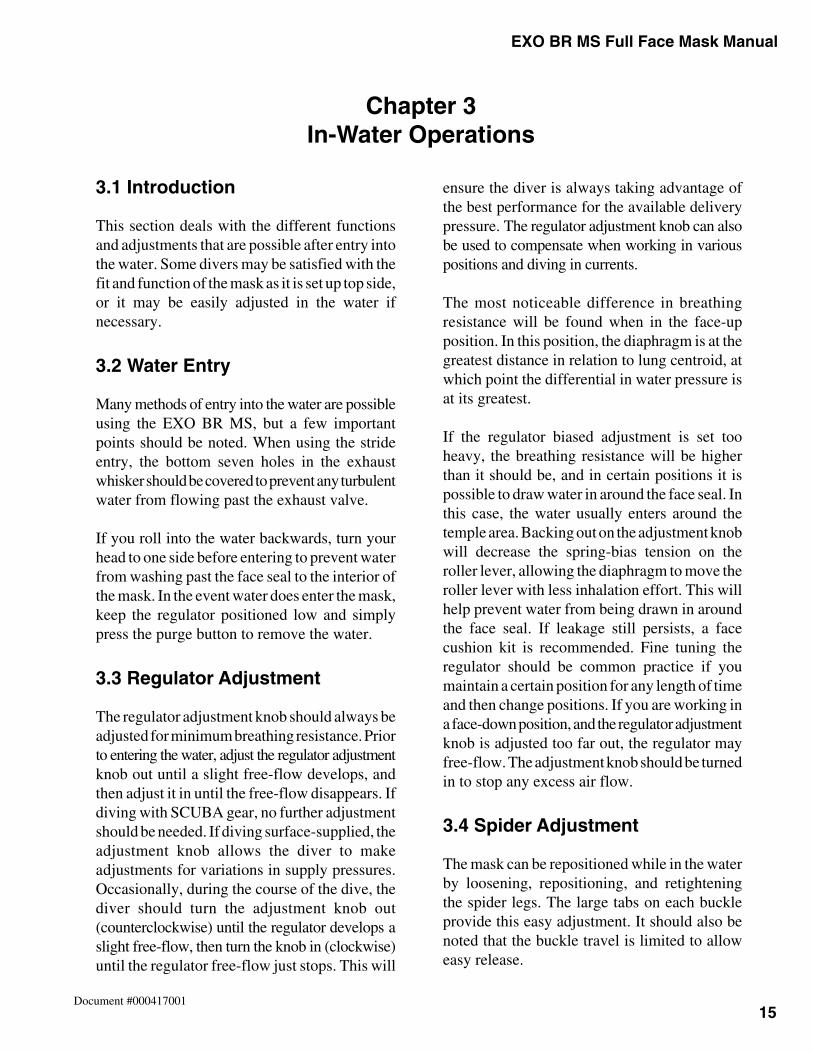
2.17.2 Mask Removal
1) Grasp the bottom of the mask on each sidewhere the buckles are attached.
2) With your thumbs, push the tabs on the twobottom buckles all the way forward and push outon the bottom of the mask at the same time. Theywill stop travelling once they hit the buckle caps.
3) At this point, push the bottom portion of themask away from the face as if it were hinged toyour forehead. This will release the bottom legs of thespider and allow quick and easy removal of the mask.
2.18 Proper Hood Fit
The type of hood that a diver chooses may havedirect bearing on the fit and comfort of the EXOBR MS. Excess material on the chin and/or jawwill keep the mask from positioning properlyand possibly cause jaw fatigue. This may alsoprevent the diver’s face from getting far enoughinto the mask for equalizing (by pinching thenose).
When using a drysuit with a latex hood, noadjustment should be needed. However, if thehood covers too much of your face, it may benecessary to trim a small amount of rubber off thechin on the hood. If using a neoprene wetsuit hood,you may want to trim material from the cheekbone downward to under the front part of the chin.
To properly trim your hood, use thefollowing procedure:
1) With the hood in position on your head, donthe mask as outlined in this chapter.
2) Have someone bend the earphone pocketsforward and start marking the hood at the edge ofthe face seal, starting at the cheekbone area.Then go down under the chin and up the otherside to the opposite cheekbone area.
3) Remove the mask and hood. Leave approximately1/4" extra material from the line marked, and trimthe excess material away.
4) Your hood should now work very well withthe mask. Because the face is in a dry air cavitybeing warmed by body heat, hood material onthe face is not needed to keep the face warm.
Diving Systems makes a hood tailored to the EXOBR MS(see Accessories, page 5). It must be trimmedin the same fashion as above. The face seal area isa thinner, two-sided skin neoprene for a superior seal.
The EXO BR MS is easily removed by the diver when necessary.
15
Chapter 3 EXO BR MS Full Face Mask Manual
Document #000417001
Chapter 3In-Water Operations
3.1 Introduction
This section deals with the different functionsand adjustments that are possible after entry intothe water. Some divers may be satisfied with thefit and function of the mask as it is set up top side,or it may be easily adjusted in the water ifnecessary.
3.2 Water Entry
Many methods of entry into the water are possibleusing the EXO BR MS, but a few importantpoints should be noted. When using the strideentry, the bottom seven holes in the exhaustwhisker should be covered to prevent any turbulentwater from flowing past the exhaust valve.
If you roll into the water backwards, turn yourhead to one side before entering to prevent waterfrom washing past the face seal to the interior ofthe mask. In the event water does enter the mask,keep the regulator positioned low and simplypress the purge button to remove the water.
3.3 Regulator Adjustment
The regulator adjustment knob should always beadjusted for minimum breathing resistance. Priorto entering the water, adjust the regulator adjustmentknob out until a slight free-flow develops, andthen adjust it in until the free-flow disappears. Ifdiving with SCUBA gear, no further adjustmentshould be needed. If diving surface-supplied, theadjustment knob allows the diver to makeadjustments for variations in supply pressures.Occasionally, during the course of the dive, thediver should turn the adjustment knob out(counterclockwise) until the regulator develops aslight free-flow, then turn the knob in (clockwise)until the regulator free-flow just stops. This will
ensure the diver is always taking advantage ofthe best performance for the available deliverypressure. The regulator adjustment knob can alsobe used to compensate when working in variouspositions and diving in currents.
The most noticeable difference in breathingresistance will be found when in the face-upposition. In this position, the diaphragm is at thegreatest distance in relation to lung centroid, atwhich point the differential in water pressure isat its greatest.
If the regulator biased adjustment is set tooheavy, the breathing resistance will be higherthan it should be, and in certain positions it ispossible to draw water in around the face seal. Inthis case, the water usually enters around thetemple area. Backing out on the adjustment knobwill decrease the spring-bias tension on theroller lever, allowing the diaphragm to move theroller lever with less inhalation effort. This willhelp prevent water from being drawn in aroundthe face seal. If leakage still persists, a facecushion kit is recommended. Fine tuning theregulator should be common practice if youmaintain a certain position for any length of timeand then change positions. If you are working ina face-down position, and the regulator adjustmentknob is adjusted too far out, the regulator mayfree-flow. The adjustment knob should be turnedin to stop any excess air flow.
3.4 Spider Adjustment
The mask can be repositioned while in the waterby loosening, repositioning, and retighteningthe spider legs. The large tabs on each buckleprovide this easy adjustment. It should also benoted that the buckle travel is limited to alloweasy release.
16
Chapter 3EXOBR MS Full Face Mask Manual
Document #000417001
The top leg of the spider can be loosened once inthe water. It is possible for the top leg to be tootight, which will cause the mask to be pulled uptoo far on the face. The main purpose for the topleg of the spider is to provide on-deck support ofthe mask. Some divers may also prefer thesupport of the top leg while in the water.
3.5 Purging the Mask
If the mask is removed and then replaced underwater,it must be cleared of water (purged). This is doneby simply holding the mask firmly on the face,keeping the regulator in a low position, anddepressing the purge button. A momentary, slightover-pressure will be felt, followed by completeremoval of all water from the interior of themask. A mask completely filled with water shouldtake no more than three seconds to completely purge.
3.6 Emergency Prodecures forSurface-Supplied Use
Loss of Air Supply1) Depress purge button.2) Back out regulator adjustment knob(counterclockwise).
3) Notify topside, and open auxiliary valve onmanifold block (if EGS is worn).4) Abort dive.
Demand Regulator Free Flow1) Turn adjustment knob in (clockwise) toreduce or stop free-flow condition.2) Notify topside.3) Upon instructions from diving supervisor,abort dive.
Fouled or Pinned Umbilical1) Report condition to topside and attempt tofree umbilical.2) If umbilical cannot be freed, await divingsupervisor’s instructions and arrival of standby diver.3) With diver’s assistance, attempt to free umbilical.4) If umbilical cannot be freed, request furtherinstructions from diving supervisor.
Excessive Breathing Resistance1) Slowly turn regulator adjustment knob(counterclockwise) for easier breathing.2) Report condition to topside.3) If excessive breathing resistance continues,press purge button during inhalation to obtain anincreased flow of air.4) If gas flow does not increase, open EGS valveto admit flow of breathing gas from emergencygas cylinder.5) Upon instructions from diving supervisor,abort dive.
Mask Flooding1) Maintain slight face-down position2) Press purge button—mask should clear withinthree seconds.3) If mask continues to flood, turn regulatoradjustment knob out (counterclockwise) until aslight free-flow develops, maintain a slight facedown attitude, and notify topside.4) Upon instructions from diving supervisor,abort dive.
WARNING: In the unlikely eventthe mask should fill with water,depressing the purge button shouldclear the mask. In the event of acontinuing flood, the adjustmentknob should be turned out to causea slight regulator free-flow. The divershould then immediately assume aface-forward position in the water toprevent the mask from floodingagain, and abort the dive.
CAUTION: Proper hood fit andspider adjustments are needed forthe mask to fit comfortably andfunction correctly.
17
Chapter 3 EXO BR MS Full Face Mask Manual
Document #000417001
4.1 Post-Dive Sanitizing
The mask should be rinsed thoroughly withfresh, clean water, and the post-dive proceduresfollowed after each day of diving (see AppendixC, Chapter 6, page 51 for Post-Dive Checklist).
1) If the mask is equipped with communications,remove and perform maintenance in accordancewith Chapter 6 of this manual.
2) The EXO BR MS should be rinsed with theregulator hooked up and pressurized. This willprevent water from entering the balance cham-ber during rinsing. The EXO BR MS requiresroutine cleaning and lubrication prior to periodsof inactivity or lay-up. If inactivity longer thanone week is planned, the inlet valve should beremoved, cleaned, and relubricated prior to storage. Ifthe mask is used daily, this maintenance shouldbe performed monthly.
3) Thoroughly rinse the entire interior and exteriorof the mask with fresh, clean water. Ensure thatall the sand and debris are removed from betweenthe EXO BR MS skeleton and mask seal, and allthe salts are removed from the regulator.
4) Purge the regulator and try to get as muchwater out of it as you can, then blow-dry the maskwith compressed air, or let air dry completely.
5) Disconnect the regulator and turn the adjustmentknob all the way out.
6) Lay the mask face down so that no water willcollect in the ear pockets. DO NOT dry the maskby placing it in direct sunlight for long periods oftime as this will degrade the rubber.
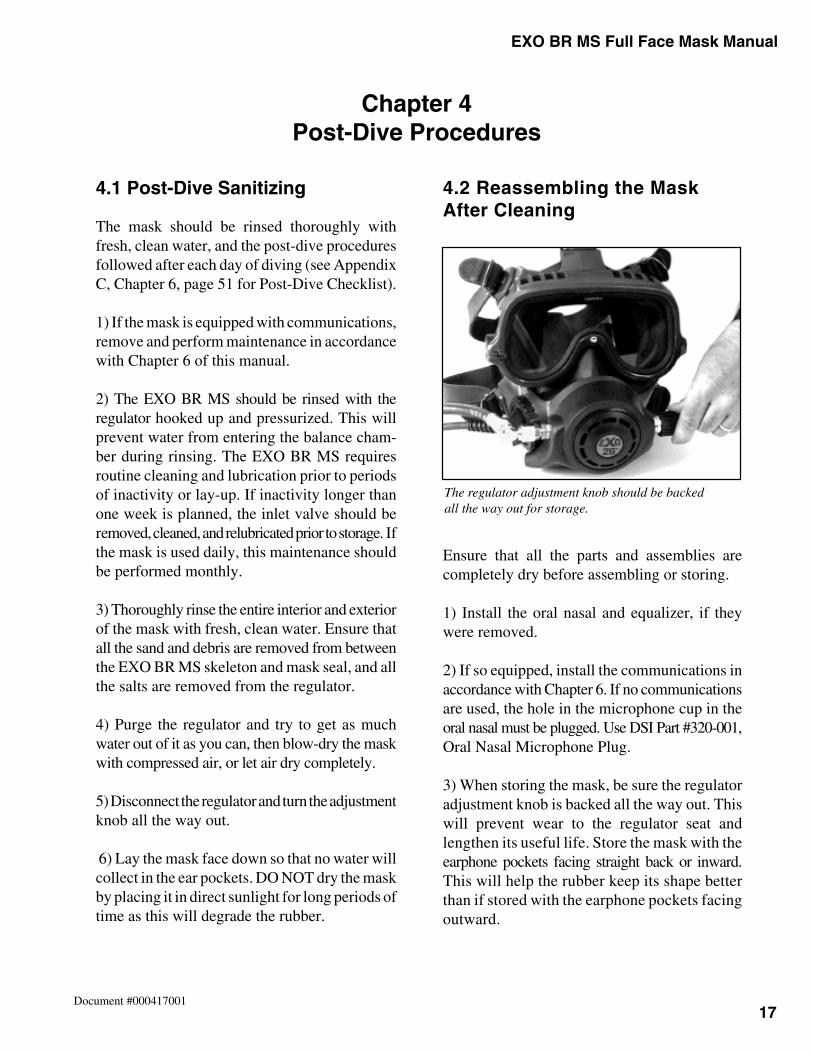
4.2 Reassembling the MaskAfter Cleaning
Ensure that all the parts and assemblies arecompletely dry before assembling or storing.
1) Install the oral nasal and equalizer, if theywere removed.
2) If so equipped, install the communications inaccordance with Chapter 6. If no communicationsare used, the hole in the microphone cup in theoral nasal must be plugged. Use DSI Part #320-001,Oral Nasal Microphone Plug.
3) When storing the mask, be sure the regulatoradjustment knob is backed all the way out. Thiswill prevent wear to the regulator seat andlengthen its useful life. Store the mask with theearphone pockets facing straight back or inward.This will help the rubber keep its shape betterthan if stored with the earphone pockets facingoutward.
Chapter 4Post-Dive Procedures
The regulator adjustment knob should be backedall the way out for storage.

18
Chapter 3EXOBR MS Full Face Mask Manual
Document #000417001
4
Notes
19
Chapter 5 EXO BR MS Full Face Mask Manual
Document #000417001
5.1 General Information
The EXO BR MS demand regulators are initiallyadjusted and preset at the DSI factory using anintermediate pressure of 135–145 psi. The maskuses a pneumatically-balanced demand valveassembly. This allows the masks to work well overa wide range of pressures and diving conditions.This demand regulator is very dependable and isvery easy to adjust and maintain. When componentsneed replacement, cleaning, or the regulator hasgone out of adjustment, read all of the followinginformation and refer to the diagrams and blow- upsections. Become familiar with all parts and termsassociated with the areas of the mask prior to anydisassembly of the regulator.
Normal annual overhauls of the EXO BR MSdemand regulators DO NOT require you tocompletely remove the regulator can body fromthe mask. Removing and reinstalling the regulatoris a difficult procedure, and will require the DSIregulator mount nut tool. Complete maskdisassembly is possible, providing the user hasthe proper DSI tools. However, it is recommendedthat this service be performed by a factory-trained DSI Dealer. Contact DSI at (805) 965-8538for your nearest factory-trained service center.
Note: If you are doing a regulator rebuild andare changing the exhaust valve, it is possible todo a replacement without completely removingthe regulator. Follow the directions for disassemblyof the regulator. Then follow the directions forremoving the regulator, but instead of taking theregulator mount nut completely off, only loosenit enough for the regulator to be pulled slightlyforward, then pull the whisker off of the regulatorbody to access the exhaust valve. Replace theexhaust valve, making sure that it is facing theright direction and seated correctly. Then putthe exhaust whisker back on and follow the directions
for installing the regulator. Following this proceduresaves you from having to remount the regulator inthe mask seal and frame, and from possible cross-threading of the regulator body while putting theregulator mount nut back on.
Chapter 5EXO BR MS Mask Maintenance
5.2 Regulator Inlet ValveMaintenance Without Removingthe Complete Demand Regulator
Tools required:13/16" open-end wrench11/16" open-end wrench5/8" DSI back-up wrenchtube brush, DSI Part #325-621nylon tooth brush
The inlet valve of the EXO BR MS requiresfrequent cleaning and lubrication due to theexacting tolerances of the inlet valve mechanism.Once familiar with this procedure, the task canbe accomplished in about 10–15 minutes. The followingprocedure is intended as a routine maintenance of theinlet valve mechanism. This procedure should beaccomplished whenever long periods of inactivityare anticipated or whenever the masks havebeen used in exceptionally harsh conditions.
CAUTION: Use only DIVING SYSTEMSINTERNATIONAL original replacementparts when repairing your mask. Theuse of other manufacturers’ parts willinterfere with the performancecharacteristics of your equipmentand may jeopardize your safety. Allof the parts listed on the explodeddrawings were specifically manufacturedby DSI for use on the EXO BR MS.When ordering spares, always in-sist on DSI original parts.
EXO BR MS Full Face Mask Manual Chapter 5
20Document #000417001
The inlet valve and balance chamber are made toexacting tolerances and need to be wellmaintained. If an annual overhaul is beingaccomplished, refer to the demand regulatorremoval section 5.4.
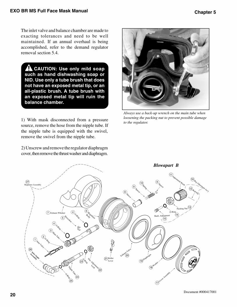
1) With mask disconnected from a pressuresource, remove the hose from the nipple tube. Ifthe nipple tube is equipped with the swivel,remove the swivel from the nipple tube.
2) Unscrew and remove the regulator diaphragmcover, then remove the thrust washer and diaphragm.
CAUTION: Use only mild soapsuch as hand dishwashing soap orNID. Use only a tube brush that doesnot have an exposed metal tip, or anall-plastic brush. A tube brush withan exposed metal tip will ruin thebalance chamber.
Always use a back-up wrench on the main tube whenloosening the packing nut to prevent possible damageto the regulator.
B
Inlet Angle
Assembly
12
3
4
7
5
4
25
6
8
9
9
24
23
22
2120
19
18
17
15
14
13
12
16
11
10
26
27
Blowapart B
21
Chapter 5 EXO BR MS Full Face Mask Manual
Document #000417001
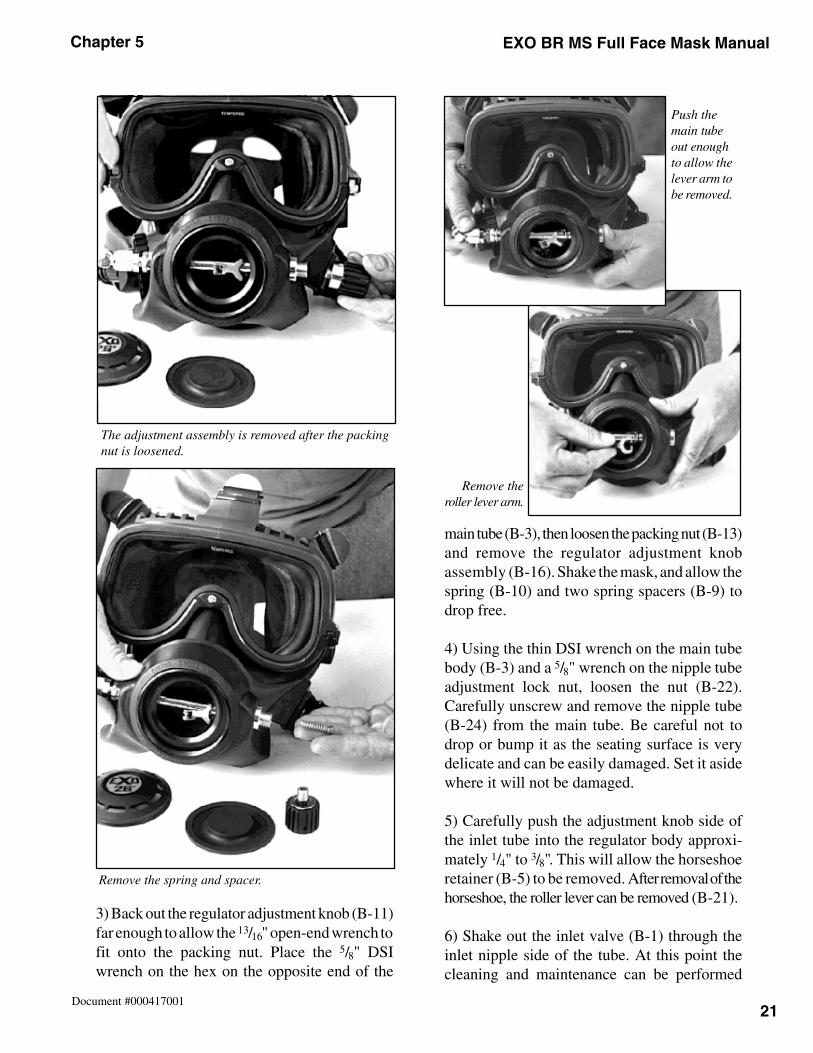
3) Back out the regulator adjustment knob (B-11)far enough to allow the 13/16" open-end wrench tofit onto the packing nut. Place the 5/8" DSIwrench on the hex on the opposite end of the
main tube (B-3), then loosen the packing nut (B-13)and remove the regulator adjustment knobassembly (B-16). Shake the mask, and allow thespring (B-10) and two spring spacers (B-9) todrop free.
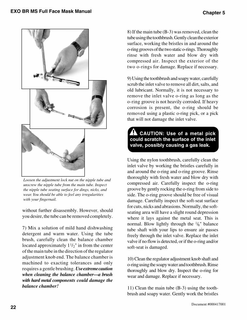
4) Using the thin DSI wrench on the main tubebody (B-3) and a 5/8" wrench on the nipple tubeadjustment lock nut, loosen the nut (B-22).Carefully unscrew and remove the nipple tube(B-24) from the main tube. Be careful not todrop or bump it as the seating surface is verydelicate and can be easily damaged. Set it asidewhere it will not be damaged.
5) Carefully push the adjustment knob side ofthe inlet tube into the regulator body approxi-mately 1/4" to 3/8". This will allow the horseshoeretainer (B-5) to be removed. After removal of thehorseshoe, the roller lever can be removed (B-21).
6) Shake out the inlet valve (B-1) through theinlet nipple side of the tube. At this point thecleaning and maintenance can be performed
Remove the spring and spacer.
Push themain tubeout enoughto allow thelever arm tobe removed.
Remove theroller lever arm.
The adjustment assembly is removed after the packingnut is loosened.
EXO BR MS Full Face Mask Manual Chapter 5
22Document #000417001
without further disassembly. However, shouldyou desire, the tube can be removed completely.
7) Mix a solution of mild hand dishwashingdetergent and warm water. Using the tubebrush, carefully clean the balance chamberlocated approximately 11/2" in from the centerof the main tube in the direction of the regulatoradjustment knob end. The balance chamber ismachined to exacting tolerances and onlyrequires a gentle brushing. Use extreme cautionwhen cleaning the balance chamber—a brushwith hard metal components could damage thebalance chamber!
8) If the main tube (B-3) was removed, clean thetube using the toothbrush. Gently clean the exteriorsurface, working the bristles in and around theo-ring grooves of the two static o-rings. Thoroughlyrinse with fresh water and blow dry withcompressed air. Inspect the exterior of thetwo o-rings for damage. Replace if necessary.
9) Using the toothbrush and soapy water, carefullyscrub the inlet valve to remove all dirt, salts, andold lubricant. Normally, it is not necessary toremove the inlet valve o-ring as long as theo-ring groove is not heavily corroded. If heavycorrosion is present, the o-ring should beremoved using a plastic o-ring pick, or a pickthat will not damage the inlet valve.
Using the nylon toothbrush, carefully clean theinlet valve by working the bristles carefully inand around the o-ring and o-ring groove. Rinsethoroughly with fresh water and blow dry withcompressed air. Carefully inspect the o-ringgroove by gently rocking the o-ring from side toside. The o-ring groove should be free of visualdamage. Carefully inspect the soft-seat surfacefor cuts, nicks and abrasions. Normally, the soft-seating area will have a slight round depressionwhere it lays against the metal seat. This isnormal. Blow lightly through the 1/8" balancetube shaft with your lips to ensure air passesfreely through the inlet valve. Replace the inletvalve if no flow is detected, or if the o-ring and/orsoft-seat is damaged.
10) Clean the regulator adjustment knob shaft ando-ring using the soapy water and toothbrush. Rinsethoroughly and blow dry. Inspect the o-ring forwear and damage. Replace if necessary.
11) Clean the main tube (B-3) using the tooth-brush and soapy water. Gently work the bristles
Loosen the adjustment lock nut on the nipple tube andunscrew the nipple tube from the main tube. Inspectthe nipple tube seating surface for dings, nicks, andwear. You should be able to feel any irregularitieswith your fingernail.
CAUTION: Use of a metal pickcould scratch the surface of the inletvalve, possibly causing a gas leak.
23
Chapter 5 EXO BR MS Full Face Mask Manual
Document #000417001
in and around the o-ring surface and threads.Rinse thoroughly with fresh water and blow dry.Carefully inspect the o-rings for damage andreplace if necessary. Carefully inspect the knife-edgeof the nipple tube for nicks and dings. The knife-edgemust be free of any damage. You should be ableto feel any irregularities with your fingernail. Ifthe tube is damaged, it must be replaced. After allparts have been cleaned and inspected, lightlylubricate all o-rings and o-ring surfaces withsilicone grease. Work the grease into the o-ringgrooves, then rotate the o-rings to spread thelubricant and wipe off any excess.
5.3 Inlet Valve Reassembly
1) After all parts have been cleaned, inspected,and lubricated lightly with silicone grease asneeded, make sure all o-rings are in theirappropriate places.
2) If the main tube was completely removedfrom the regulator body, reinstall it by sliding itinto the regulator body. The “B” that is machinedinto the main tube at the nipple end should befacing the front of the mask. Keep sliding thetube in until the horseshoe area of the main tubeis centered in the regulator body. If the main tubewas not removed, it will already be positionedfor acceptance of the horseshoe retainer.
3) Slide the horseshoe (B-5) into place on themain tube from inside the mask.
4) Slide the inlet valve (B-1) into the main tubefrom the nipple tube side, sliding it in until theinlet valve is seated into the tube.
5) Slide the roller lever (B-21) into the rollerlever slot on the main tube. Make sure that theinlet valve is caught by the roller lever, and thenpush the main tube (B-3) all the way into theregulator body. Make sure that the exhaust whisker(B-7) is seated in the groove around the maintube at the nipple tube end.
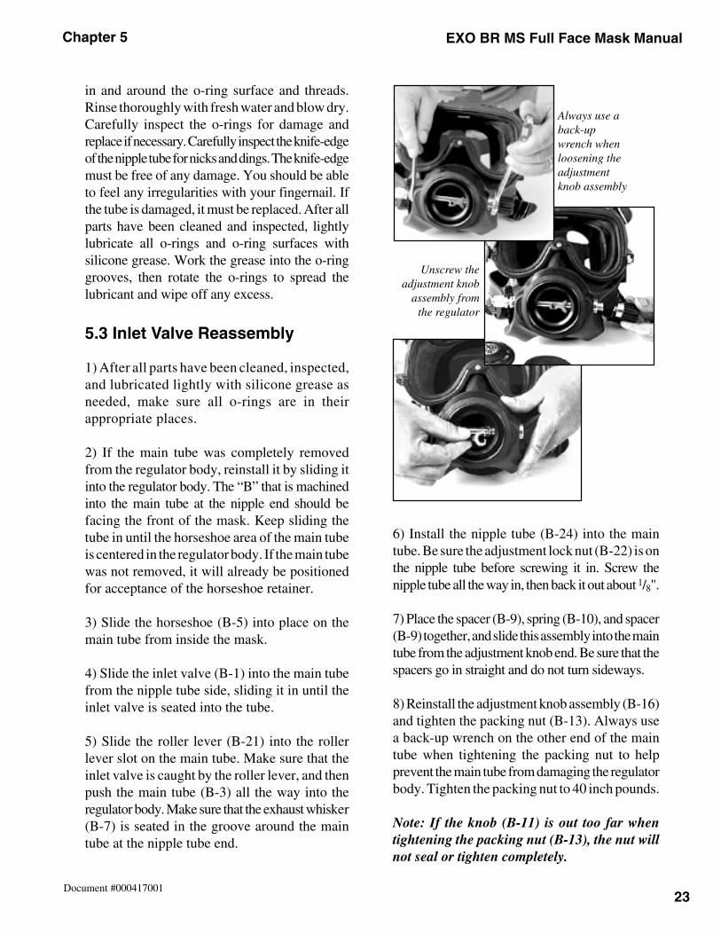
6) Install the nipple tube (B-24) into the maintube. Be sure the adjustment lock nut (B-22) is onthe nipple tube before screwing it in. Screw thenipple tube all the way in, then back it out about 1/8".
7) Place the spacer (B-9), spring (B-10), and spacer(B-9) together, and slide this assembly into the maintube from the adjustment knob end. Be sure that thespacers go in straight and do not turn sideways.
8) Reinstall the adjustment knob assembly (B-16)and tighten the packing nut (B-13). Always usea back-up wrench on the other end of the maintube when tightening the packing nut to helpprevent the main tube from damaging the regulatorbody. Tighten the packing nut to 40 inch pounds.
Note: If the knob (B-11) is out too far whentightening the packing nut (B-13), the nut willnot seal or tighten completely.
Unscrew theadjustment knob
assembly fromthe regulator
Always use aback-upwrench whenloosening theadjustmentknob assembly
EXO BR MS Full Face Mask Manual Chapter 5
24Document #000417001
16) Hold one hand inside the oral nasal cavity toprevent the regulator from running away andfully depress the purge button. A strong flow ofgas should be felt. The regulator should notfree- flow when the purge button is released.
5.4 Complete Regulator AssemblyRemoval for Annual Overhaul
Tools required:3/8" ratchet with an extensionEXO BR MS Tool Kit, Deluxe, DSI Part #325-650
If you are going to attempt this procedure, read theprocedure over before you start any disassembly.
5.4.1 Regulator Assembly Removal
1) Remove spider and communications module.
2) Remove the oral nasal mask (A-26).
3) On the EXO BR MS, remove the screws (A-24)and washers (A-23) that hold the wire retainer(A-22) on, and remove the wire retainer.
4) Install the regulator mount nut tool on a 3/8"ratchet with an extension.
5) With the mask face down in your lap, place theregulator mount nut tool in the grooves of theregulator mount nut (A-21). Unscrew and removethe regulator mount nut.
6) Remove the mount ring (A-20).
7) Gently pull straight out on the regulatorassembly (A-11), removing it from the mask.Remove the regulator mount washer (A-19) fromthe inside of the mask.
9) Slowly rotate the nipple tube in until theroller lever starts to move down approximately1/4" to 3/8". Check the lever play with a finger.Lever play should be º to 3/8 of an inch. This is aninitial setting only!
10) Install the diaphragm (B-19), washer (B-18)and regulator cover assembly (B-17), and tightenby hand.
11) Turn adjustment knob (B-11) all the way in,then back it out three full turns.
12) Reinstall the intermediate hose and swivel,and bring up air pressure from a regulated pressuresource at between 135–145 psig.
Note: Rotating the nipple tube in (clockwise)decreases the lever height, resulting in less airflow and roller lever travel. Rotating the nippletube out (counterclockwise) results in more airflow and more lever travel, but if taken too farwill result in free-flow.
13) Adjust the regulator by placing the DSIspanner against the regulator cover so that theraised portion of the spanner depresses the purgebutton while the rest of the spanner lays flushagainst the cover.
14) Rotate the main tube (B-3) in or out asnecessary until a slight flow of gas can be heard.The flow of gas should stop as soon as thespanner is removed. End result is the regulatorpurge button should travel inward the length ofthe raised portion of the wrench before a flow ofgas is heard. And the flow should stop when thebutton is released.
15) Using a back-up wrench on the main tube (B-3),tighten the lock nut (B-22) on the nipple tube (B-24),then recheck the regulator purge travel as outlinedin step above to make sure the setting did notchange during the tightening of the lock nut tothe main tube.
25
Chapter 5 EXO BR MS Full Face Mask Manual
Document #000417001
5.4.2 Balanced Regulator Disassembly
1) Unscrew and remove the regulator diaphragmcover, then remove the thrust washer and diaphragm.
2) Back out the regulator adjustment knob (B-11)far enough to allow the 13/16" open-end wrench tofit onto the packing nut. Place the 5/8" DSIwrench on the hex on the opposite end of themain tube (B-3), then loosen the packing nut (B-13)and remove the regulator adjustment knobassembly (B-16). Shake the mask, and allow thespring (B-10) and two spring spacers (B-9)to drop free.
3) Using the thin DSI wrench on the main tubebody (B-3) and a standard 5/8" wrench on thenipple tube jam nut, loosen the adjustment locknut (B-22). Carefully unscrew and remove thenipple tube (B-24) from the main tube. Be carefulnot to drop or bump it as the seating surface isvery delicate and can be easily damaged. Set itaside where it will not be damaged.
4) Carefully push the adjustment knob side of theinlet tube into the regulator body approximately1/4" to 3/8". This will allow the horseshoe retainer(B-5) to be removed. After removal of the horseshoe,the roller lever can be removed (B-21).
5) Shake out the inlet valve (B-1) through theinlet nipple side of the tube.
6) Remove the main tube (B-3).
Note: When removing o-rings, use only a plasticor brass o-ring pick. Use of a metal pick couldcause damage to the o-ring surfaces.
7) Remove the two main tube o-rings (B-4)and discard.
5.4.3 Regulator Maintenance
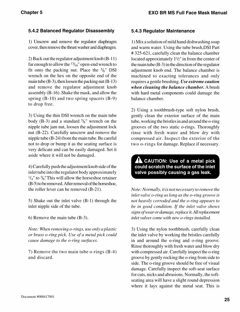
1) Mix a solution of mild hand dishwashing soapand warm water. Using the tube brush,DSI Part# 325-621, carefully clean the balance chamberlocated approximately 1 1/2" in from the center ofthe main tube (B-3) in the direction of the regulatoradjustment knob end. The balance chamber ismachined to exacting tolerances and onlyrequires a gentle brushing. Use extreme cautionwhen cleaning the balance chamber. A brushwith hard metal components could damage thebalance chamber.
2) Using a toothbrush-type soft nylon brush,gently clean the exterior surface of the maintube, working the bristles in and around the o-ringgrooves of the two static o-rings. Thoroughlyrinse with fresh water and blow dry withcompressed air. Inspect the exterior of thetwo o-rings for damage. Replace if necessary.
Note: Normally, it is not necessary to remove theinlet valve o-ring as long as the o-ring groove isnot heavily corroded and the o-ring appears tobe in good condition. If the inlet valve showssigns of wear or damage, replace it. All replacementinlet valves come with new o-rings installed.
3) Using the nylon toothbrush, carefully cleanthe inlet valve by working the bristles carefullyin and around the o-ring and o-ring groove.Rinse thoroughly with fresh water and blow drywith compressed air. Carefully inspect the o-ringgroove by gently rocking the o-ring from side toside. The o-ring groove should be free of visualdamage. Carefully inspect the soft-seat surfacefor cuts, nicks and abrasions. Normally, the soft-seating area will have a slight round depressionwhere it lays against the metal seat. This is
CAUTION: Use of a metal pickcould scratch the surface of the inletvalve possibly causing a gas leak.
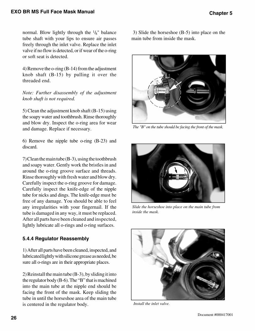
EXO BR MS Full Face Mask Manual Chapter 5
26Document #000417001
The "B" on the tube should be facing the front of the mask.
3) Slide the horseshoe (B-5) into place on themain tube from inside the mask.
Slide the horseshoe into place on the main tube frominside the mask.
Install the inlet valve.
normal. Blow lightly through the 1/8" balancetube shaft with your lips to ensure air passesfreely through the inlet valve. Replace the inletvalve if no flow is detected, or if wear of the o-ringor soft seat is detected.
4) Remove the o-ring (B-14) from the adjustmentknob shaft (B-15) by pulling it over thethreaded end.
Note: Further disassembly of the adjustmentknob shaft is not required.
5) Clean the adjustment knob shaft (B-15) usingthe soapy water and toothbrush. Rinse thoroughlyand blow dry. Inspect the o-ring area for wearand damage. Replace if necessary.
6) Remove the nipple tube o-ring (B-23) anddiscard.
7) Clean the main tube (B-3), using the toothbrushand soapy water. Gently work the bristles in andaround the o-ring groove surface and threads.Rinse thoroughly with fresh water and blow dry.Carefully inspect the o-ring groove for damage.Carefully inspect the knife-edge of the nippletube for nicks and dings. The knife-edge must befree of any damage. You should be able to feelany irregularities with your fingernail. If thetube is damaged in any way, it must be replaced.After all parts have been cleaned and inspected,lightly lubricate all o-rings and o-ring surfaces.
5.4.4 Regulator Reassembly
1) After all parts have been cleaned, inspected, andlubricated lightly with silicone grease as needed, besure all o-rings are in their appropriate places.
2) Reinstall the main tube (B-3), by sliding it intothe regulator body (B-6). The “B” that is machinedinto the main tube at the nipple end should befacing the front of the mask. Keep sliding thetube in until the horseshoe area of the main tubeis centered in the regulator body.
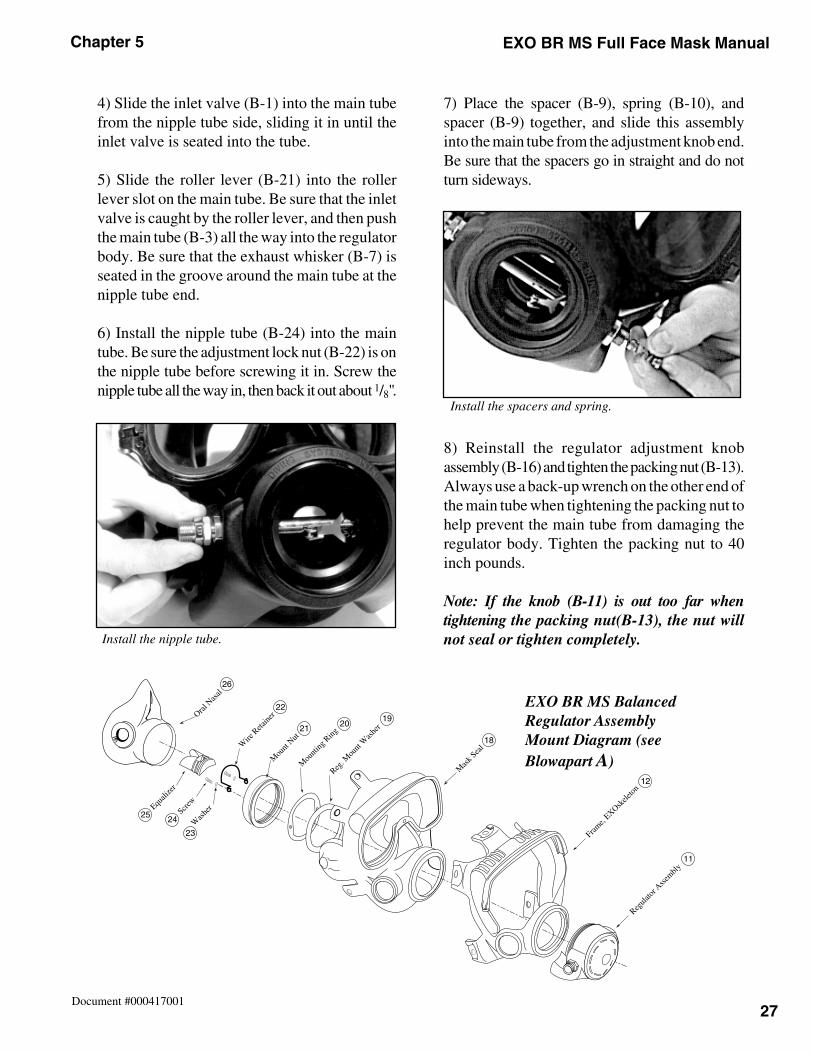
27
Chapter 5 EXO BR MS Full Face Mask Manual
Document #000417001
4) Slide the inlet valve (B-1) into the main tubefrom the nipple tube side, sliding it in until theinlet valve is seated into the tube.
5) Slide the roller lever (B-21) into the rollerlever slot on the main tube. Be sure that the inletvalve is caught by the roller lever, and then pushthe main tube (B-3) all the way into the regulatorbody. Be sure that the exhaust whisker (B-7) isseated in the groove around the main tube at thenipple tube end.
6) Install the nipple tube (B-24) into the maintube. Be sure the adjustment lock nut (B-22) is onthe nipple tube before screwing it in. Screw thenipple tube all the way in, then back it out about 1/8".
7) Place the spacer (B-9), spring (B-10), andspacer (B-9) together, and slide this assemblyinto the main tube from the adjustment knob end.Be sure that the spacers go in straight and do notturn sideways.
8) Reinstall the regulator adjustment knobassembly (B-16) and tighten the packing nut (B-13).Always use a back-up wrench on the other end ofthe main tube when tightening the packing nut tohelp prevent the main tube from damaging theregulator body. Tighten the packing nut to 40inch pounds.
Note: If the knob (B-11) is out too far whentightening the packing nut(B-13), the nut willnot seal or tighten completely. Install the nipple tube.
Install the spacers and spring.
12
18
11
192021
22
26
25 24
23
EXO BR MS BalancedRegulator AssemblyMount Diagram (seeBlowapart A)
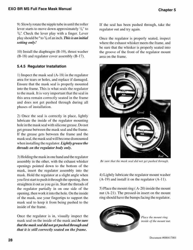
EXO BR MS Full Face Mask Manual Chapter 5
28Document #000417001
Place the mount ringinside of the mount nut.
If the seal has been pushed through, take theregulator out and try again.
Once the regulator is properly seated, inspectwhere the exhaust whisker meets the frame, andbe sure that the whisker is properly seated intothe groove of the front of the regulator mountarea on the frame.
4) Lightly lubricate the regulator mount washer(A-19) and install it on the regulator (A-11).
5) Place the mount ring ( A-20) inside the mountnut (A-21). The pressed-in insert on the mountring should have the bumps facing the regulator.
Be sure that the mask seal did not get pushed through.
Good
Bad
9) Slowly rotate the nipple tube in until the rollerlever starts to move down approximately 1/4" to3/8". Check the lever play with a finger. Leverplay should be º to 3/8 of an inch. This is an initialsetting only!
10) Install the diaphragm (B-19), thrust washer(B-18) and regulator cover assembly (B-17).
5.4.5 Regulator Installation
1) Inspect the mask seal (A-18) in the regulatorarea for tears or holes, and replace if damaged.Ensure that the mask seal is properly mountedinto the frame. This is what seals the regulatorto the mask. It is very important that the seal inthis area remain correctly seated in the frameand does not get pushed through during allphases of installation.
2) Once the seal is correctly in place, lightlylubricate the inside of the regulator mountinghole in the mask seal with silicone grease. Do notget grease between the mask seal and the frame.If the grease gets between the frame and themask seal, the mask seal will become dismountedwhen installing the regulator. Lightly grease thethreads on the regulator body only.
3) Holding the mask in one hand and the regulatorassembly in the other, with the exhaust whiskeropenings pointed down to the bottom of themask, insert the regulator assembly into themask. Hold the regulator at a slight angle whenyou first start to push it through the opening, thenstraighten it out as you go in. Start the threads ofthe regulator partially in on one side of theopening, then work it into the hole. On the insideof the mask, use your fingertips to support themask seal to keep it from being pushed to theinside of the frame.
Once the regulator is in, visually inspect themask seal on the inside of the mask and be surethat the mask seal did not get pushed through andthat it is still correctly seated on the frame.
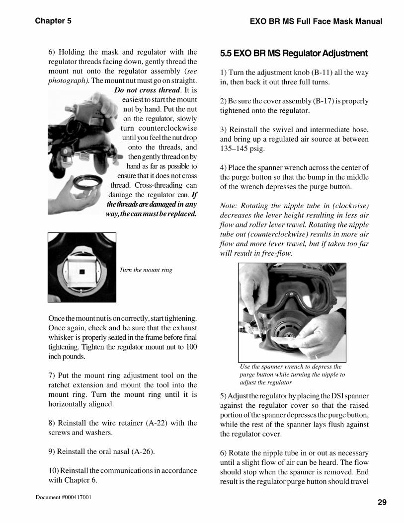
29
Chapter 5 EXO BR MS Full Face Mask Manual
Document #000417001
6) Holding the mask and regulator with theregulator threads facing down, gently thread themount nut onto the regulator assembly (seephotograph). The mount nut must go on straight.
Do not cross thread. It iseasiest to start the mountnut by hand. Put the nuton the regulator, slowly
turn counterclockwiseuntil you feel the nut drop
onto the threads, andthen gently thread on byhand as far as possible to
ensure that it does not crossthread. Cross-threading can
damage the regulator can. Ifthe threads are damaged in anyway, the can must be replaced.
Once the mount nut is on correctly, start tightening.Once again, check and be sure that the exhaustwhisker is properly seated in the frame before finaltightening. Tighten the regulator mount nut to 100inch pounds.
7) Put the mount ring adjustment tool on theratchet extension and mount the tool into themount ring. Turn the mount ring until it ishorizontally aligned.
8) Reinstall the wire retainer (A-22) with thescrews and washers.
9) Reinstall the oral nasal (A-26).
10) Reinstall the communications in accordancewith Chapter 6.
5.5 EXO BR MS Regulator Adjustment
1) Turn the adjustment knob (B-11) all the wayin, then back it out three full turns.
2) Be sure the cover assembly (B-17) is properlytightened onto the regulator.
3) Reinstall the swivel and intermediate hose,and bring up a regulated air source at between135–145 psig.
4) Place the spanner wrench across the center ofthe purge button so that the bump in the middleof the wrench depresses the purge button.
Note: Rotating the nipple tube in (clockwise)decreases the lever height resulting in less airflow and roller lever travel. Rotating the nippletube out (counterclockwise) results in more airflow and more lever travel, but if taken too farwill result in free-flow.
5) Adjust the regulator by placing the DSI spanneragainst the regulator cover so that the raisedportion of the spanner depresses the purge button,while the rest of the spanner lays flush againstthe regulator cover.
6) Rotate the nipple tube in or out as necessaryuntil a slight flow of air can be heard. The flowshould stop when the spanner is removed. Endresult is the regulator purge button should travel
Turn the mount ring
Use the spanner wrench to depress thepurge button while turning the nipple toadjust the regulator
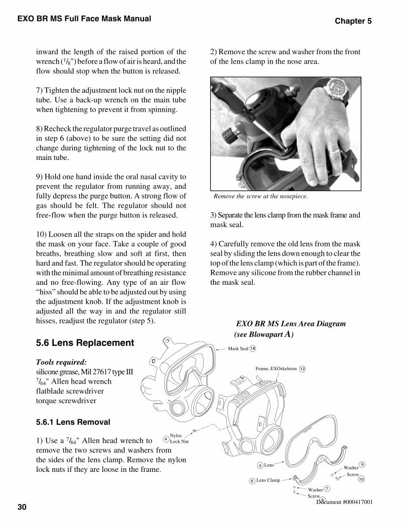
EXO BR MS Full Face Mask Manual Chapter 5
30Document #000417001
4
12
18
5
6
9
10
7
8
inward the length of the raised portion of thewrench (1/8") before a flow of air is heard, and theflow should stop when the button is released.
7) Tighten the adjustment lock nut on the nippletube. Use a back-up wrench on the main tubewhen tightening to prevent it from spinning.
8) Recheck the regulator purge travel as outlinedin step 6 (above) to be sure the setting did notchange during tightening of the lock nut to themain tube.
9) Hold one hand inside the oral nasal cavity toprevent the regulator from running away, andfully depress the purge button. A strong flow ofgas should be felt. The regulator should notfree-flow when the purge button is released.
10) Loosen all the straps on the spider and holdthe mask on your face. Take a couple of goodbreaths, breathing slow and soft at first, thenhard and fast. The regulator should be operatingwith the minimal amount of breathing resistanceand no free-flowing. Any type of an air flow“hiss” should be able to be adjusted out by usingthe adjustment knob. If the adjustment knob isadjusted all the way in and the regulator stillhisses, readjust the regulator (step 5).
5.6 Lens Replacement
Tools required:silicone grease, Mil 27617 type III7/64" Allen head wrenchflatblade screwdrivertorque screwdriver
5.6.1 Lens Removal
1) Use a 7/64" Allen head wrench toremove the two screws and washers fromthe sides of the lens clamp. Remove the nylonlock nuts if they are loose in the frame.
2) Remove the screw and washer from the frontof the lens clamp in the nose area.
3) Separate the lens clamp from the mask frame andmask seal.
4) Carefully remove the old lens from the maskseal by sliding the lens down enough to clear thetop of the lens clamp (which is part of the frame).Remove any silicone from the rubber channel inthe mask seal.
EXO BR MS Lens Area Diagram(see Blowapart A)
Remove the screw at the nosepiece.
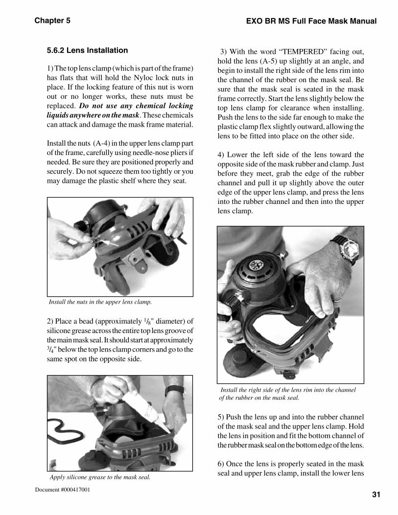
31
Chapter 5 EXO BR MS Full Face Mask Manual
Document #000417001
5.6.2 Lens Installation
1) The top lens clamp (which is part of the frame)has flats that will hold the Nyloc lock nuts inplace. If the locking feature of this nut is wornout or no longer works, these nuts must bereplaced. Do not use any chemical lockingliquids anywhere on the mask. These chemicalscan attack and damage the mask frame material.
Install the nuts (A-4) in the upper lens clamp partof the frame, carefully using needle-nose pliers ifneeded. Be sure they are positioned properly andsecurely. Do not squeeze them too tightly or youmay damage the plastic shelf where they seat.
2) Place a bead (approximately 1/8" diameter) ofsilicone grease across the entire top lens groove ofthe main mask seal. It should start at approximately3/4" below the top lens clamp corners and go to thesame spot on the opposite side.
3) With the word “TEMPERED” facing out,hold the lens (A-5) up slightly at an angle, andbegin to install the right side of the lens rim intothe channel of the rubber on the mask seal. Besure that the mask seal is seated in the maskframe correctly. Start the lens slightly below thetop lens clamp for clearance when installing.Push the lens to the side far enough to make theplastic clamp flex slightly outward, allowing thelens to be fitted into place on the other side.
4) Lower the left side of the lens toward theopposite side of the mask rubber and clamp. Justbefore they meet, grab the edge of the rubberchannel and pull it up slightly above the outeredge of the upper lens clamp, and press the lensinto the rubber channel and then into the upperlens clamp.
5) Push the lens up and into the rubber channelof the mask seal and the upper lens clamp. Holdthe lens in position and fit the bottom channel ofthe rubber mask seal on the bottom edge of the lens.
6) Once the lens is properly seated in the maskseal and upper lens clamp, install the lower lens
Install the nuts in the upper lens clamp.
Apply silicone grease to the mask seal.
Install the right side of the lens rim into the channelof the rubber on the mask seal.
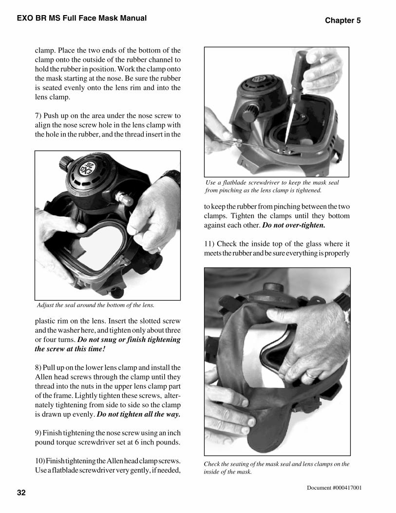
EXO BR MS Full Face Mask Manual Chapter 5
32Document #000417001
Check the seating of the mask seal and lens clamps on theinside of the mask.
clamp. Place the two ends of the bottom of theclamp onto the outside of the rubber channel tohold the rubber in position. Work the clamp ontothe mask starting at the nose. Be sure the rubberis seated evenly onto the lens rim and into thelens clamp.
7) Push up on the area under the nose screw toalign the nose screw hole in the lens clamp withthe hole in the rubber, and the thread insert in the
plastic rim on the lens. Insert the slotted screwand the washer here, and tighten only about threeor four turns. Do not snug or finish tighteningthe screw at this time!
8) Pull up on the lower lens clamp and install theAllen head screws through the clamp until theythread into the nuts in the upper lens clamp partof the frame. Lightly tighten these screws, alter-nately tightening from side to side so the clampis drawn up evenly. Do not tighten all the way.
9) Finish tightening the nose screw using an inchpound torque screwdriver set at 6 inch pounds.
10) Finish tightening the Allen head clamp screws.Use a flatblade screwdriver very gently, if needed,
to keep the rubber from pinching between the twoclamps. Tighten the clamps until they bottomagainst each other. Do not over-tighten.
11) Check the inside top of the glass where itmeets the rubber and be sure everything is properly
Use a flatblade screwdriver to keep the mask sealfrom pinching as the lens clamp is tightened.
Adjust the seal around the bottom of the lens.
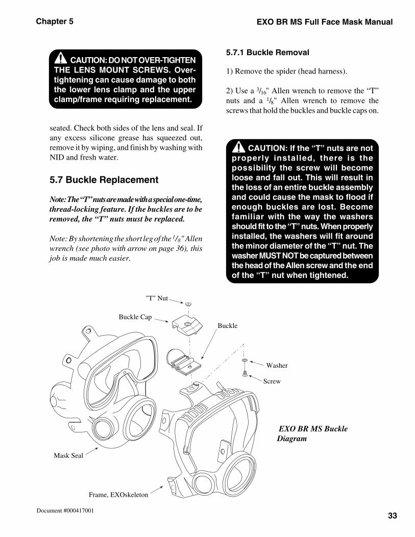
33
Chapter 5 EXO BR MS Full Face Mask Manual
Document #000417001
EXO BR MS BuckleDiagram
seated. Check both sides of the lens and seal. Ifany excess silicone grease has squeezed out,remove it by wiping, and finish by washing withNID and fresh water.
5.7 Buckle Replacement
Note: The “T” nuts are made with a special one-time,thread-locking feature. If the buckles are to beremoved, the “T” nuts must be replaced.
Note: By shortening the short leg of the 1/8" Allenwrench (see photo with arrow on page 36), thisjob is made much easier.
5.7.1 Buckle Removal
1) Remove the spider (head harness).
2) Use a 3/16" Allen wrench to remove the “T”nuts and a 1/8" Allen wrench to remove thescrews that hold the buckles and buckle caps on.
CAUTION: DO NOT OVER-TIGHTENTHE LENS MOUNT SCREWS. Over-tightening can cause damage to boththe lower lens clamp and the upperclamp/frame requiring replacement.
CAUTION: If the “T” nuts are notproperly installed, there is thepossibility the screw will becomeloose and fall out. This will result inthe loss of an entire buckle assemblyand could cause the mask to flood ifenough buckles are lost. Becomefamiliar with the way the washersshould fit to the “T” nuts. When properlyinstalled, the washers will fit aroundthe minor diameter of the “T” nut. Thewasher MUST NOT be captured betweenthe head of the Allen screw and the endof the “T” nut when tightened.
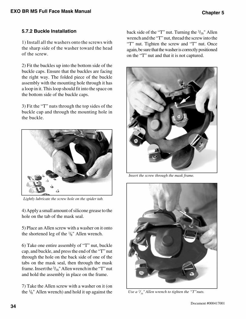
EXO BR MS Full Face Mask Manual Chapter 5
34Document #000417001
5.7.2 Buckle Installation
1) Install all the washers onto the screws withthe sharp side of the washer toward the headof the screw.
2) Fit the buckles up into the bottom side of thebuckle caps. Ensure that the buckles are facingthe right way. The folded piece of the buckleassembly with the mounting hole through it hasa loop in it. This loop should fit into the space onthe bottom side of the buckle caps.
3) Fit the “T” nuts through the top sides of thebuckle cap and through the mounting hole inthe buckle.
4) Apply a small amount of silicone grease to thehole on the tab of the mask seal.
5) Place an Allen screw with a washer on it ontothe shortened leg of the 1/8" Allen wrench.
6) Take one entire assembly of “T” nut, bucklecap, and buckle, and press the end of the “T” nutthrough the hole on the back side of one of thetabs on the mask seal, then through the maskframe. Insert the 3/16" Allen wrench in the “T” nutand hold the assembly in place on the frame.
7) Take the Allen screw with a washer on it (onthe 1/8" Allen wrench) and hold it up against the
back side of the “T” nut. Turning the 3/16" Allenwrench and the “T” nut, thread the screw into the“T” nut. Tighten the screw and “T” nut. Onceagain, be sure that the washer is correctly positionedon the “T” nut and that it is not captured.
Lightly lubricate the screw hole on the spider tab.
Use a 3/16
" Allen wrench to tighten the “T”nuts.
Insert the screw through the mask frame.
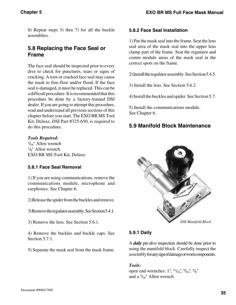
35
Chapter 5 EXO BR MS Full Face Mask Manual
Document #000417001
8) Repeat steps 3) thru 7) for all the buckleassemblies.
5.8 Replacing the Face Seal orFrame
The face seal should be inspected prior to everydive to check for punctures, tears or signs ofcracking. A torn or cracked face seal may causethe mask to free-flow and/or flood. If the faceseal is damaged, it must be replaced. This can bea difficult procedure. It is recommended that thisprocedure be done by a factory-trained DSIdealer. If you are going to attempt this procedure,read and understand all previous sections of thischapter before you start. The EXO BR MS ToolKit, Deluxe, DSI Part #325-650, is required todo this procedure.
Tools Required:3/16" Allen wrench1/8" Allen wrenchEXO BR MS Tool Kit, Deluxe
5.8.1 Face Seal Removal
1) If you are using communications, remove thecommunications module, microphone andearphones. See Chapter 6.
2) Release the spider from the buckles and remove.
3) Remove the regulator assembly. See Section 5.4.1.
3) Remove the lens. See Section 5.6.1.
4) Remove the buckles and buckle caps. SeeSection 5.7.1.
5) Separate the mask seal from the mask frame.
5.8.2 Face Seal Installation
1) Put the mask seal into the frame. Seat the lensseal area of the mask seal into the upper lensclamp part of the frame. Seat the regulator andcomm module areas of the mask seal in thecorrect spots on the frame.
2) Install the regulator assembly. See Section 5.4.5.
3) Install the lens. See Section 5.6.2
4) Install the buckles and spider. See Section 5.7.
5) Install the communications module.See Chapter 6.
5.9 Manifold Block Maintenance
5.9.1 Daily
A daily pre-dive inspection should be done prior tousing the manifold block. Carefully inspect theassembly for any sign of damage or worn components.
Tools:open end wrenches: 1", 11/16", 9/16", 5/8"and a 5/16" Allen wrench
DSI Manifold Block
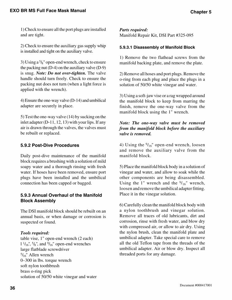
EXO BR MS Full Face Mask Manual Chapter 5
36Document #000417001
1) Check to ensure all the port plugs are installedand are tight.
2) Check to ensure the auxiliary gas supply whipis installed and tight on the auxiliary valve.
3) Using a 5/8" open-end wrench, check to ensurethe packing nut (D-4) on the auxiliary valve (D-9)is snug. Note: Do not over-tighten. The valvehandle should turn freely. Check to ensure thepacking nut does not turn (when a light force isapplied with the wrench).
4) Ensure the one-way valve (D-14) and umbilicaladapter are securely in place.
5) Test the one-way valve (14) by sucking on theinlet adapter (D-11, 12, 13) with your lips. If anyair is drawn through the valves, the valves mustbe rebuilt or replaced.
5.9.2 Post-Dive Procedures
Daily post-dive maintenance of the manifoldblock requires a brushing with a solution of mildsoapy water and a thorough rinsing with freshwater. If hoses have been removed, ensure portplugs have been installed and the umbilicalconnection has been capped or bagged.
5.9.3 Annual Overhaul of the ManifoldBlock Assembly
The DSI manifold block should be rebuilt on anannual basis, or when damage or corrosion issuspected or found.
Tools required:table vise, 1" open-end wrench (2 each)l 1/16", 5/8", and 9/16" open-end wrencheslarge flatblade screwdriver5/16" Allen wrench0–300 in lbs. torque wrenchsoft nylon toothbrushbrass o-ring picksolution of 50/50 white vinegar and water
Parts required:Manifold Repair Kit, DSI Part #325-095
5.9.3.1 Disassembly of Manifold Block
1) Remove the two flathead screws from themanifold backing plate, and remove the plate.
2) Remove all hoses and port plugs. Remove theo-ring from each plug and place the plugs in asolution of 50/50 white vinegar and water.
3) Using a soft-jaw vise or a rag wrapped aroundthe manifold block to keep from marring thefinish, remove the one-way valve from themanifold block using the 1" wrench.
Note: The one-way valve must be removedfrom the manifold block before the auxiliaryvalve is removed.
4) Using the 9/16" open-end wrench, loosenand remove the auxiliary valve from themanifold block.
5) Place the manifold block body in a solution ofvinegar and water, and allow to soak while theother components are being disassembled.Using the 1" wrench and the 9/16" wrench,loosen and remove the umbilical adapter fitting.Place it in the vinegar solution.
6) Carefully clean the manifold block body witha nylon toothbrush and vinegar solution.Remove all traces of old lubricants, dirt andcorrosion, rinse with fresh water, and blow drywith compressed air, or allow to air dry. Usingthe nylon brush, clean the manifold plate andumbilical adapter. Take special care to removeall the old Teflon tape from the threads of theumbilical adapter. Air or blow dry. Inspect allthreaded ports for any damage.
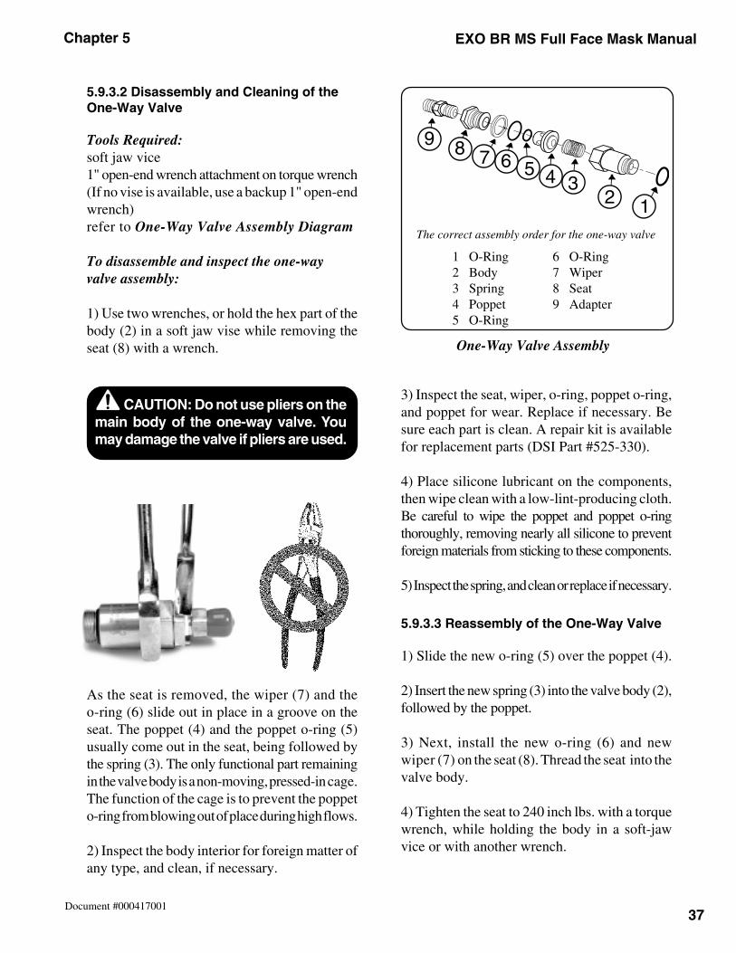
37
Chapter 5 EXO BR MS Full Face Mask Manual
Document #000417001
5.9.3.2 Disassembly and Cleaning of theOne-Way Valve
Tools Required:soft jaw vice1" open-end wrench attachment on torque wrench(If no vise is available, use a backup 1" open-endwrench)refer to One-Way Valve Assembly Diagram
To disassemble and inspect the one-wayvalve assembly:
1) Use two wrenches, or hold the hex part of thebody (2) in a soft jaw vise while removing theseat (8) with a wrench.
As the seat is removed, the wiper (7) and theo-ring (6) slide out in place in a groove on theseat. The poppet (4) and the poppet o-ring (5)usually come out in the seat, being followed bythe spring (3). The only functional part remainingin the valve body is a non-moving, pressed-in cage.The function of the cage is to prevent the poppeto-ring from blowing out of place during high flows.
2) Inspect the body interior for foreign matter ofany type, and clean, if necessary.
3) Inspect the seat, wiper, o-ring, poppet o-ring,and poppet for wear. Replace if necessary. Besure each part is clean. A repair kit is availablefor replacement parts (DSI Part #525-330).
4) Place silicone lubricant on the components,then wipe clean with a low-lint-producing cloth.Be careful to wipe the poppet and poppet o-ringthoroughly, removing nearly all silicone to preventforeign materials from sticking to these components.
5) Inspect the spring, and clean or replace if necessary.
5.9.3.3 Reassembly of the One-Way Valve
1) Slide the new o-ring (5) over the poppet (4).
2) Insert the new spring (3) into the valve body (2),followed by the poppet.
3) Next, install the new o-ring (6) and newwiper (7) on the seat (8). Thread the seat into thevalve body.
4) Tighten the seat to 240 inch lbs. with a torquewrench, while holding the body in a soft-jawvice or with another wrench.
CAUTION: Do not use pliers on themain body of the one-way valve. Youmay damage the valve if pliers are used.
123456789
The correct assembly order for the one-way valve
1 O-Ring2 Body3 Spring4 Poppet5 O-Ring
6 O-Ring7 Wiper8 Seat9 Adapter
One-Way Valve Assembly
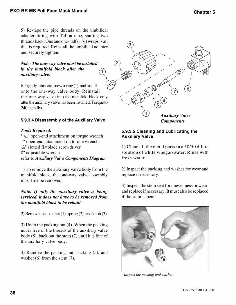
EXO BR MS Full Face Mask Manual Chapter 5
38Document #000417001
5) Re-tape the pipe threads on the umbilicaladapter fitting with Teflon tape, starting twothreads back. One and one-half (1 1/2) wraps is allthat is required. Reinstall the umbilical adapterand securely tighten.
Note: The one-way valve must be installedin the manifold block after theauxiliary valve.
6. Lightly lubricate a new o-ring (1), and installonto the one-way valve body. Reinstallthe one-way valve into the manifold block onlyafter the auxiliary valve has been installed. Torque to240 inch lbs.
5.9.3.4 Disassembly of the Auxiliary Valve
Tools Required:11/16" open-end attachment on torque wrench1" open-end attachment on torque wrench3/8" slotted flatblade screwdriver8" adjustable wrenchrefer to Auxiliary Valve Components Diagram
1) To remove the auxiliary valve body from themanifold block, the one-way valve assemblymust first be removed.
Note: If only the auxiliary valve is beingserviced, it does not have to be removed fromthe manifold block to be rebuilt.
2) Remove the lock nut (1), spring (2), and knob (3).
3) Undo the packing nut (4). When the packingnut is free of the threads of the auxiliary valvebody (8), back out the stem (7) until it is free ofthe auxiliary valve body.
4) Remove the packing nut, packing (5), andwasher (6) from the stem (7).
5.9.3.5 Cleaning and Lubricating theAuxiliary Valve
1) Clean all the metal parts in a 50/50 dilutesolution of white vinegar/water. Rinse withfresh water.
2) Inspect the packing and washer for wear andreplace if necessary.
3) Inspect the stem seat for unevenness or wear,and replace if necessary. It must also be replacedif the stem is bent.
1
2
3
4
56
78
Auxiliary ValveComponents
Inspect the packing and washer.
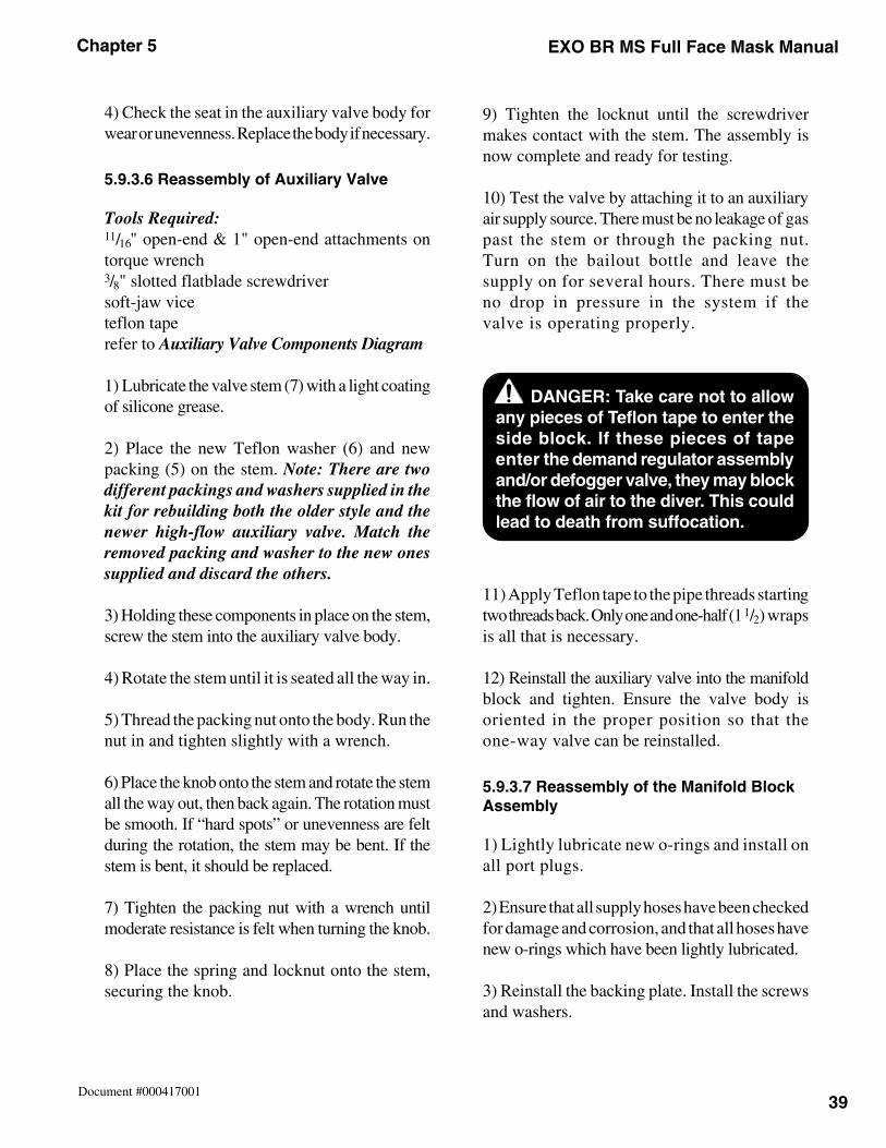
39
Chapter 5 EXO BR MS Full Face Mask Manual
Document #000417001
4) Check the seat in the auxiliary valve body forwear or unevenness. Replace the body if necessary.
5.9.3.6 Reassembly of Auxiliary Valve
Tools Required:11/16" open-end & 1" open-end attachments ontorque wrench3/8" slotted flatblade screwdriversoft-jaw viceteflon taperefer to Auxiliary Valve Components Diagram
1) Lubricate the valve stem (7) with a light coatingof silicone grease.
2) Place the new Teflon washer (6) and newpacking (5) on the stem. Note: There are twodifferent packings and washers supplied in thekit for rebuilding both the older style and thenewer high-flow auxiliary valve. Match theremoved packing and washer to the new onessupplied and discard the others.
3) Holding these components in place on the stem,screw the stem into the auxiliary valve body.
4) Rotate the stem until it is seated all the way in.
5) Thread the packing nut onto the body. Run thenut in and tighten slightly with a wrench.
6) Place the knob onto the stem and rotate the stemall the way out, then back again. The rotation mustbe smooth. If “hard spots” or unevenness are feltduring the rotation, the stem may be bent. If thestem is bent, it should be replaced.
7) Tighten the packing nut with a wrench untilmoderate resistance is felt when turning the knob.
8) Place the spring and locknut onto the stem,securing the knob.
9) Tighten the locknut until the screwdrivermakes contact with the stem. The assembly isnow complete and ready for testing.
10) Test the valve by attaching it to an auxiliaryair supply source. There must be no leakage of gaspast the stem or through the packing nut.Turn on the bailout bottle and leave thesupply on for several hours. There must beno drop in pressure in the system if thevalve is operating properly.
11) Apply Teflon tape to the pipe threads startingtwo threads back. Only one and one-half (1 1/2) wrapsis all that is necessary.
12) Reinstall the auxiliary valve into the manifoldblock and tighten. Ensure the valve body isoriented in the proper position so that theone-way valve can be reinstalled.
5.9.3.7 Reassembly of the Manifold BlockAssembly
1) Lightly lubricate new o-rings and install onall port plugs.
2) Ensure that all supply hoses have been checkedfor damage and corrosion, and that all hoses havenew o-rings which have been lightly lubricated.
3) Reinstall the backing plate. Install the screwsand washers.
DANGER: Take care not to allowany pieces of Teflon tape to enter theside block. If these pieces of tapeenter the demand regulator assemblyand/or defogger valve, they may blockthe flow of air to the diver. This couldlead to death from suffocation.
EXO BR MS Full Face Mask Manual Chapter 5
40Document #000417001
4) Reinstall all hoses and perform a test of thesystem. Prior to assembling a bailout system, theone-way valve and auxiliary valve should betested for proper function.
Equipment Needed:
• manifold block• bailout bottle• 1st stage regulator w/octopus and SCUBA reg hose attached• DCS system with an umbilical supply hose• bucket of water
Testing the One-Way Valve
1) With all the accessory holes plugged on themanifold block, attach the SCUBA-type regulatorhose from a first stage regulator that also has anoctopus attached, to the auxiliary valve on themanifold block assembly. The octopus will be usedfor depressurization once the test is concluded.
2) Connect the first stage to the bailout bottle,open the auxiliary valve all the way, and pressurizethe system.
3) Place the pressurized manifold block in abucket of water and check the one-way valve forleaks. No air should leak through the one-wayvalve or from anywhere else on the manifoldblock assembly. If there is a leak, the one-wayvalve must be rebuilt or replaced.
4) As a secondary test, close the auxiliary valve,trapping pressure inside the manifold blockassembly and relieve the pressure on the firststage using the octopus. Disconnect the hosefrom the auxiliary valve.
5) Quickly open the auxiliary valve by turningthe knob. You should hear the trapped air escapingthrough the auxiliary valve.
Testing the Auxiliary Valve
1) With all the accessory holes plugged on themanifold block, attach the umbilical hose to theone-way valve.
2) Make sure that the auxiliary valve is closed allthe way and pressurize the umbilical.
3) Place the pressurized manifold block in abucket of water and check the auxiliary valvefor leaks. No air should leak through the auxiliaryvalve or from anywhere else on the auxiliaryvalve assembly or manifold block assembly.If there is a leak, the auxiliary valve must berebuilt or replaced.
4) Turn umbilical off and open the auxiliaryvalve to depressurize the system and disconnectthe hose.
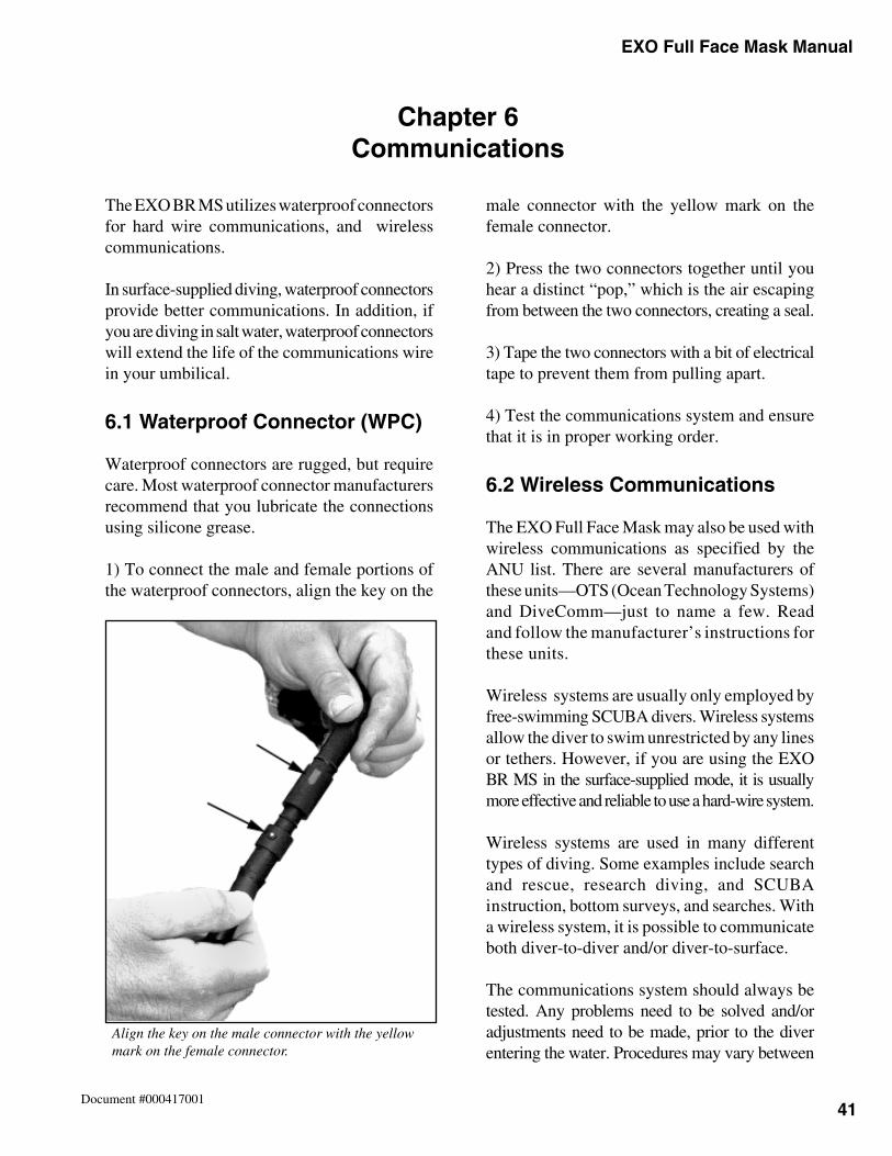
41
Chapter 6 EXO Full Face Mask Manual
Document #000417001
The EXO BR MS utilizes waterproof connectorsfor hard wire communications, and wirelesscommunications.
In surface-supplied diving, waterproof connectorsprovide better communications. In addition, ifyou are diving in salt water, waterproof connectorswill extend the life of the communications wirein your umbilical.
6.1 Waterproof Connector (WPC)
Waterproof connectors are rugged, but requirecare. Most waterproof connector manufacturersrecommend that you lubricate the connectionsusing silicone grease.
1) To connect the male and female portions ofthe waterproof connectors, align the key on the
male connector with the yellow mark on thefemale connector.
2) Press the two connectors together until youhear a distinct “pop,” which is the air escapingfrom between the two connectors, creating a seal.
3) Tape the two connectors with a bit of electricaltape to prevent them from pulling apart.
4) Test the communications system and ensurethat it is in proper working order.
6.2 Wireless Communications
The EXO Full Face Mask may also be used withwireless communications as specified by theANU list. There are several manufacturers ofthese units—OTS (Ocean Technology Systems)and DiveComm—just to name a few. Readand follow the manufacturer’s instructions forthese units.
Wireless systems are usually only employed byfree-swimming SCUBA divers. Wireless systemsallow the diver to swim unrestricted by any linesor tethers. However, if you are using the EXOBR MS in the surface-supplied mode, it is usuallymore effective and reliable to use a hard-wire system.
Wireless systems are used in many differenttypes of diving. Some examples include searchand rescue, research diving, and SCUBAinstruction, bottom surveys, and searches. Witha wireless system, it is possible to communicateboth diver-to-diver and/or diver-to-surface.
The communications system should always betested. Any problems need to be solved and/oradjustments need to be made, prior to the diverentering the water. Procedures may vary between
Chapter 6Communications
Align the key on the male connector with the yellowmark on the female connector.
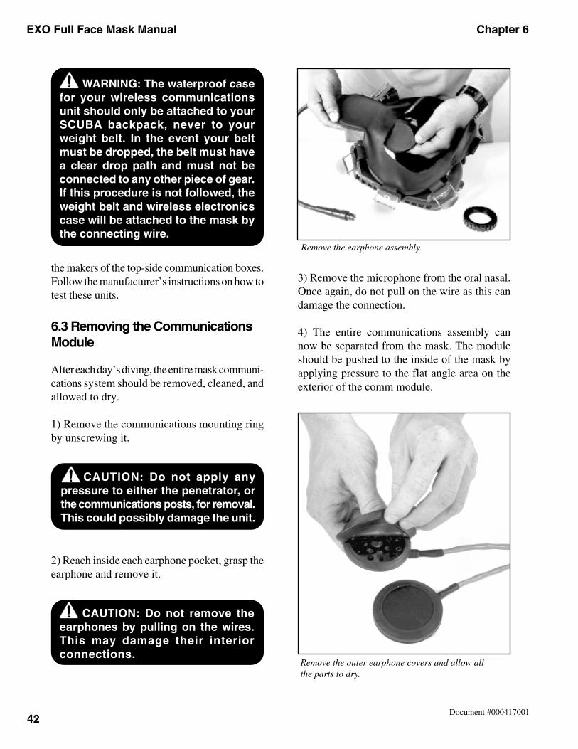
EXO Full Face Mask Manual Chapter 6
42Document #000417001
the makers of the top-side communication boxes.Follow the manufacturer’s instructions on how totest these units.
6.3 Removing the CommunicationsModule
After each day’s diving, the entire mask communi-cations system should be removed, cleaned, andallowed to dry.
1) Remove the communications mounting ringby unscrewing it.
2) Reach inside each earphone pocket, grasp theearphone and remove it.
3) Remove the microphone from the oral nasal.Once again, do not pull on the wire as this candamage the connection.
4) The entire communications assembly cannow be separated from the mask. The moduleshould be pushed to the inside of the mask byapplying pressure to the flat angle area on theexterior of the comm module.
Remove the outer earphone covers and allow allthe parts to dry.
WARNING: The waterproof casefor your wireless communicationsunit should only be attached to yourSCUBA backpack, never to yourweight belt. In the event your beltmust be dropped, the belt must havea clear drop path and must not beconnected to any other piece of gear.If this procedure is not followed, theweight belt and wireless electronicscase will be attached to the mask bythe connecting wire.
CAUTION: Do not apply anypressure to either the penetrator, orthe communications posts, for removal.This could possibly damage the unit.
CAUTION: Do not remove theearphones by pulling on the wires.This may damage their interiorconnections.
Remove the earphone assembly.
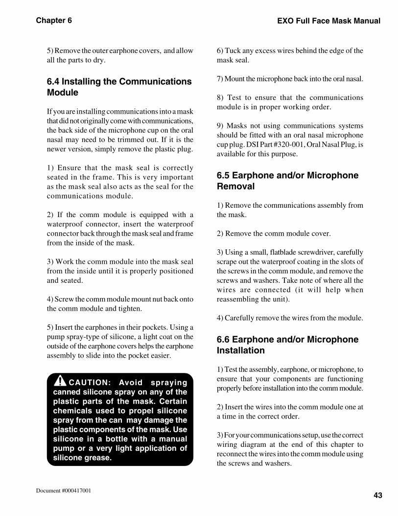
43
Chapter 6 EXO Full Face Mask Manual
Document #000417001
5) Remove the outer earphone covers, and allowall the parts to dry.
6.4 Installing the CommunicationsModule
If you are installing communications into a maskthat did not originally come with communications,the back side of the microphone cup on the oralnasal may need to be trimmed out. If it is thenewer version, simply remove the plastic plug.
1) Ensure that the mask seal is correctlyseated in the frame. This is very importantas the mask seal also acts as the seal for thecommunications module.
2) If the comm module is equipped with awaterproof connector, insert the waterproofconnector back through the mask seal and framefrom the inside of the mask.
3) Work the comm module into the mask sealfrom the inside until it is properly positionedand seated.
4) Screw the comm module mount nut back ontothe comm module and tighten.
5) Insert the earphones in their pockets. Using apump spray-type of silicone, a light coat on theoutside of the earphone covers helps the earphoneassembly to slide into the pocket easier.
6) Tuck any excess wires behind the edge of themask seal.
7) Mount the microphone back into the oral nasal.
8) Test to ensure that the communicationsmodule is in proper working order.
9) Masks not using communications systemsshould be fitted with an oral nasal microphonecup plug. DSI Part #320-001, Oral Nasal Plug, isavailable for this purpose.
6.5 Earphone and/or MicrophoneRemoval
1) Remove the communications assembly fromthe mask.
2) Remove the comm module cover.
3) Using a small, flatblade screwdriver, carefullyscrape out the waterproof coating in the slots ofthe screws in the comm module, and remove thescrews and washers. Take note of where all thewires are connected (it will help whenreassembling the unit).
4) Carefully remove the wires from the module.
6.6 Earphone and/or MicrophoneInstallation
1) Test the assembly, earphone, or microphone, toensure that your components are functioningproperly before installation into the comm module.
2) Insert the wires into the comm module one ata time in the correct order.
3) For your communications setup, use the correctwiring diagram at the end of this chapter toreconnect the wires into the comm module usingthe screws and washers.
CAUTION: Avoid sprayingcanned silicone spray on any of theplastic parts of the mask. Certainchemicals used to propel siliconespray from the can may damage theplastic components of the mask. Usesilicone in a bottle with a manualpump or a very light application ofsilicone grease.
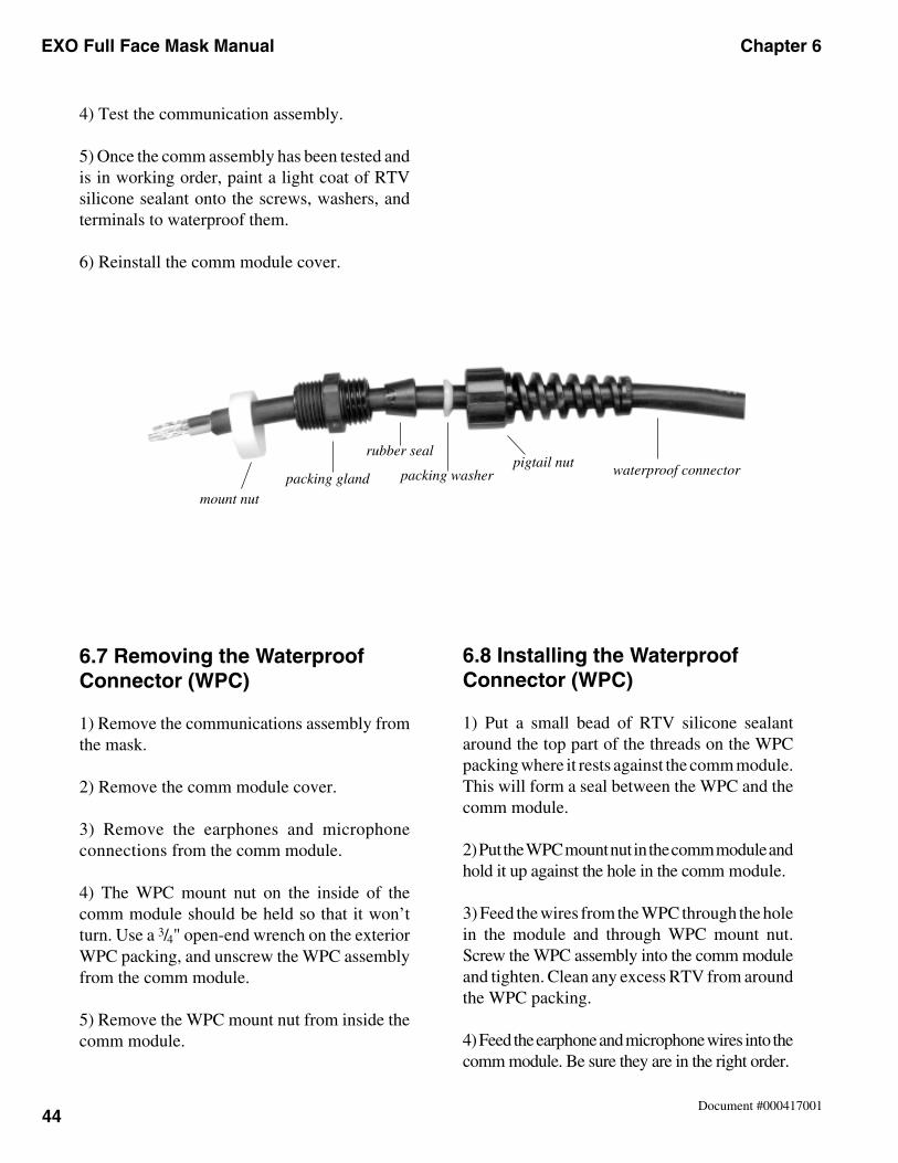
EXO Full Face Mask Manual Chapter 6
44Document #000417001
6.8 Installing the WaterproofConnector (WPC)
1) Put a small bead of RTV silicone sealantaround the top part of the threads on the WPCpacking where it rests against the comm module.This will form a seal between the WPC and thecomm module.
2) Put the WPC mount nut in the comm module andhold it up against the hole in the comm module.
3) Feed the wires from the WPC through the holein the module and through WPC mount nut.Screw the WPC assembly into the comm moduleand tighten. Clean any excess RTV from aroundthe WPC packing.
4) Feed the earphone and microphone wires into thecomm module. Be sure they are in the right order.
4) Test the communication assembly.
5) Once the comm assembly has been tested andis in working order, paint a light coat of RTVsilicone sealant onto the screws, washers, andterminals to waterproof them.
6) Reinstall the comm module cover.
6.7 Removing the WaterproofConnector (WPC)
1) Remove the communications assembly fromthe mask.
2) Remove the comm module cover.
3) Remove the earphones and microphoneconnections from the comm module.
4) The WPC mount nut on the inside of thecomm module should be held so that it won’tturn. Use a 3/4" open-end wrench on the exteriorWPC packing, and unscrew the WPC assemblyfrom the comm module.
5) Remove the WPC mount nut from inside thecomm module.
waterproof connectorpacking washerpacking gland
rubber seal
mount nut
pigtail nut
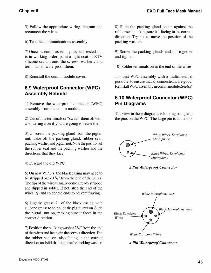
45
Chapter 6 EXO Full Face Mask Manual
Document #000417001
5) Follow the appropriate wiring diagram andreconnect the wires.
6) Test the communications assembly.
7) Once the comm assembly has been tested andis in working order, paint a light coat of RTVsilicone sealant onto the screws, washers, andterminals to waterproof them.
8) Reinstall the comm module cover.
6.9 Waterproof Connector (WPC)Assembly Rebuild
1) Remove the waterproof connector (WPC)assembly from the comm module.
2) Cut off the terminals or “sweat” them off witha soldering iron if you are going to reuse them.
3) Unscrew the packing gland from the pigtailnut. Take off the packing gland, rubber seal,packing washer and pigtail nut. Note the position ofthe rubber seal and the packing washer and thedirections that they face.
4) Discard the old WPC.
5) On new WPC’s, the black casing may need tobe stripped back 11/4" from the end of the wires.The tips of the wires usually come already strippedand dipped in solder. If not, strip the end of thewires 1/4" and solder the ends to prevent fraying.
6) Lightly grease 2" of the black casing withsilicone grease to help slide the pigtail nut on. Slidethe pigtail nut on, making sure it faces in thecorrect direction.
7) Position the packing washer 2 1/4" from the endof the wires and facing in the correct direction. Putthe rubber seal on, also facing in the correctdirection, and slide it up against the packing washer.
8) Slide the packing gland on up against therubber seal, making sure it is facing in the correctdirection. Try not to move the position of thepacking washer.
9) Screw the packing glands and nut togetherand tighten.
10) Solder terminals on to the end of the wires.
11) Test WPC assembly with a multimeter, ifpossible, to ensure that all connections are good.Reinstall WPC assembly in comm module. See 6.8.
6.10 Waterproof Connector (WPC)Pin Diagrams
The view in these diagrams is looking straight atthe pins on the WPC. The large pin is at the top.
White Wires, EarphonesMicrophone
Black Wires, EarphonesMicrophone
2 Pin Waterproof Connector
4 Pin Waterproof Connector
White Microphone Wire
Black Microphone Wire
White Earphone Wires
Black Earphone Wires
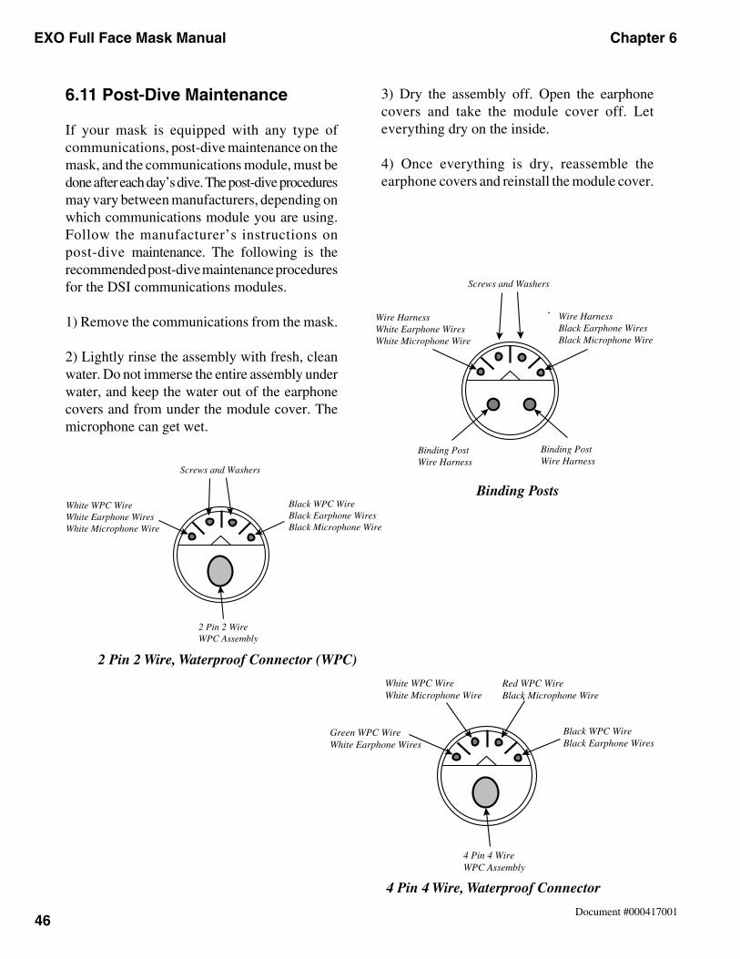
EXO Full Face Mask Manual Chapter 6
46Document #000417001
6.11 Post-Dive Maintenance
If your mask is equipped with any type ofcommunications, post-dive maintenance on themask, and the communications module, must bedone after each day’s dive. The post-dive proceduresmay vary between manufacturers, depending onwhich communications module you are using.Follow the manufacturer’s instructions onpost-dive maintenance. The following is therecommended post-dive maintenance proceduresfor the DSI communications modules.
1) Remove the communications from the mask.
2) Lightly rinse the assembly with fresh, cleanwater. Do not immerse the entire assembly underwater, and keep the water out of the earphonecovers and from under the module cover. Themicrophone can get wet.
Binding Posts
Screws and Washers
Wire HarnessWhite Earphone WiresWhite Microphone Wire
Wire HarnessBlack Earphone WiresBlack Microphone Wire
Binding Post Wire Harness
Binding Post Wire Harness
4 Pin 4 Wire, Waterproof Connector
Green WPC WireWhite Earphone Wires
Black WPC WireBlack Earphone Wires
White WPC WireWhite Microphone Wire
Red WPC WireBlack Microphone Wire
4 Pin 4 Wire WPC Assembly
2 Pin 2 Wire, Waterproof Connector (WPC)
Screws and Washers
2 Pin 2 Wire WPC Assembly
White WPC WireWhite Earphone WiresWhite Microphone Wire
Black WPC WireBlack Earphone WiresBlack Microphone Wire
3) Dry the assembly off. Open the earphonecovers and take the module cover off. Leteverything dry on the inside.
4) Once everything is dry, reassemble theearphone covers and reinstall the module cover.
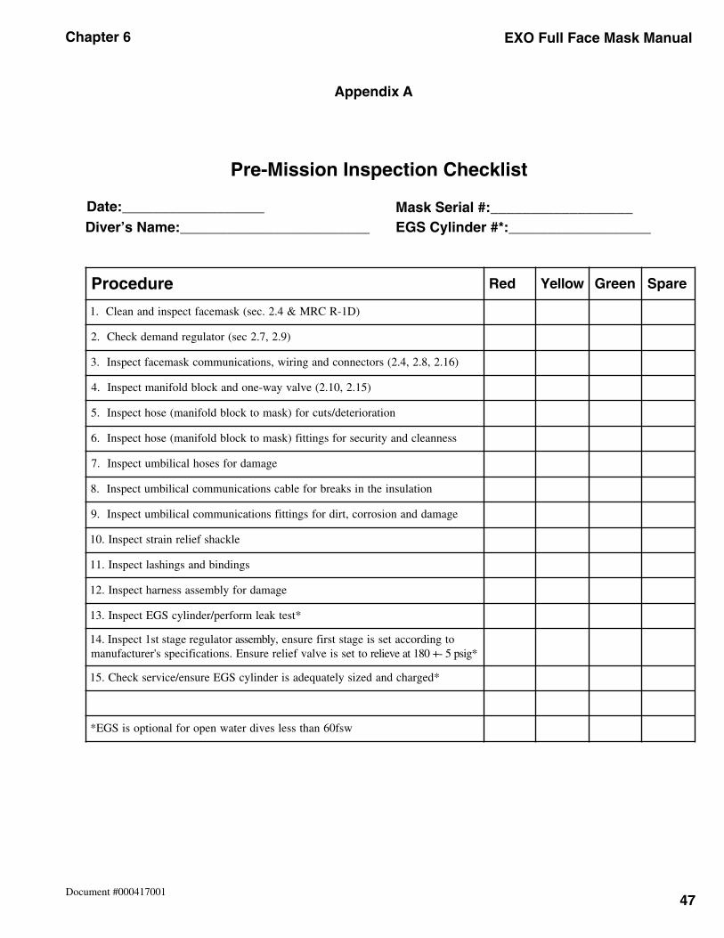
47
Chapter 6 EXO Full Face Mask Manual
Document #000417001
Appendix A
Pre-Mission Inspection Checklist
Date:__________________Diver’s Name:________________________
Mask Serial #:__________________EGS Cylinder #*:__________________
erudecorP deR wolleY neerG erapS
)D1-RCRM&4.2.ces(ksamecaftcepsnidnanaelC.1
)9.2,7.2ces(rotalugerdnamedkcehC.2
)61.2,8.2,4.2(srotcennocdnagniriw,snoitacinummocksamecaftcepsnI.3
)51.2,01.2(evlavyaw-enodnakcolbdlofinamtcepsnI.4
noitaroireted/stucrof)ksamotkcolbdlofinam(esohtcepsnI.5
ssennaelcdnaytirucesrofsgnittif)ksamotkcolbdlofinam(esohtcepsnI.6
egamadrofsesohlacilibmutcepsnI.7
noitalusniehtniskaerbrofelbacsnoitacinummoclacilibmutcepsnI.8
egamaddnanoisorroc,tridrofsgnittifsnoitacinummoclacilibmutcepsnI.9
elkcahsfeilerniartstcepsnI.01
sgnidnibdnasgnihsaltcepsnI.11
egamadrofylbmessassenrahtcepsnI.21
*tsetkaelmrofrep/rednilycSGEtcepsnI.31
ylbmessarotalugeregatsts1tcepsnI.41 otgnidroccatessiegatstsriferusne,ottessievlavfeilererusnE.snoitacificepss'rerutcafunam *gisp5-+081taeveiler
*degrahcdnadezisyletauqedasirednilycSGEerusne/ecivreskcehC.51
wsf06nahtsselsevidretawneporoflanoitposiSGE*
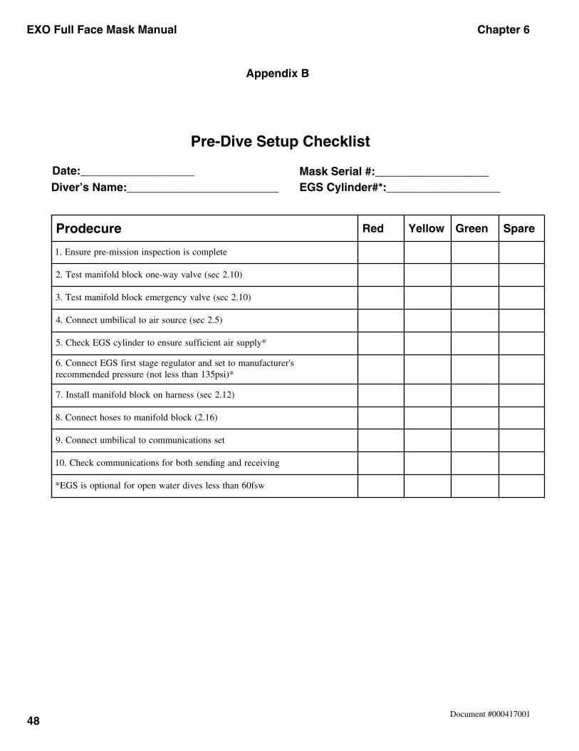
EXO Full Face Mask Manual Chapter 6
48Document #000417001
Appendix B
Pre-Dive Setup Checklist
Date:__________________Diver’s Name:________________________
Mask Serial #:__________________EGS Cylinder#*:__________________
erucedorP deR wolleY neerG erapS
etelpmocsinoitcepsninoissim-erperusnE.1
)01.2ces(evlavyaw-enokcolbdlofinamtseT.2
)01.2ces(evlavycnegremekcolbdlofinamtseT.3
)5.2ces(ecruosriaotlacilibmutcennoC.4
*ylppusriatneiciffuserusneotrednilycSGEkcehC.5
s'rerutcafunamottesdnarotalugeregatstsrifSGEtcennoC.6*)isp531nahtsselton(erusserpdednemmocer
)21.2ces(ssenrahnokcolbdlofinamllatsnI.7
)61.2(kcolbdlofinamotsesohtcennoC.8
tessnoitacinummocotlacilibmutcennoC.9
gniviecerdnagnidneshtobrofsnoitacinummockcehC.01
wsf06nahtsselsevidretawneporoflanoitposiSGE*
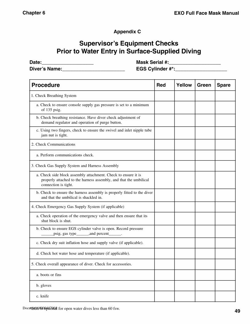
49
Chapter 6 EXO Full Face Mask Manual
Document #000417001
Appendix C
Supervisor’s Equipment ChecksPrior to Water Entry in Surface-Supplied Diving
Date:___________________Diver’s Name:_______________________
Mask Serial #:___________________EGS Cylinder #*:___________________
*EGS is optional for open water dives less than 60 fsw.
erudecorP deR wolleY neerG erapS
metsySgnihtaerBkcehC.1
muminimaottessierusserpsagylppuselosnocerusneotkcehC.a.gisp531fo
fotnemtsujdakcehcrevidevaH.ecnatsisergnihtaerbkcehC.b.nottubegrupfonoitarepodnarotalugerdnamed
ebutelppintelnidnaleviwsehterusneotkcehc,sregnifowtgnisU.c.thgitsitunmaj
snoitacinummoCkcehC.2
.kcehcsnoitacinummocmrofreP.a
ylbmessAssenraHdnametsySylppuSsaGkcehC.3
sitierusneotkcehC.tnemhcattaylbmessakcolbediskcehC.alacilibmuehttahtdna,ylbmessassenrahehtotdehcattaylreporp
.thgitsinoitcennoc
revidehtotdettifylreporpsiylbmessassenrahehterusneotkcehC.b.nidelkcahssilacilibmuehttahtdna
)elbacilppafi(metsySylppuSsaGycnegremEkcehC.4
stitahterusnenehtdnaevlavycnegremeehtfonoitarepokcehC.a.tuhssikcolbtuhs
erusserpdroceR.neposievlavrednilycSGEerusneotkcehC.b.______tnecrepdna,______epytsag,gisp______
.)elbacilppafi(evlavylppusdnaesohnoitalfnitiusyrdkcehC.c
.)elbacilppafi(erutarepmetdnaesohretawtohkcehC.d
.seirosseccarofkcehC.revidfoecnaraeppallarevokcehC.5
snifrostoob.a
sevolg.b
efink.c
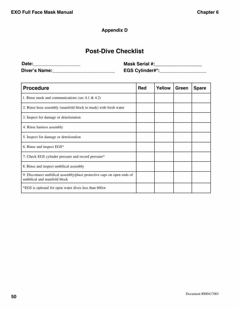
EXO Full Face Mask Manual Chapter 6
50Document #000417001
Appendix D
erudecorP deR wolleY neerG erapS
)2.4&1.4ces(snoitacinummocdnaksamesniR.1
retawhserfhtiw)ksamotkcolbdlofinam(ylbmessaesohesniR.2
noitaroiretedroegamadroftcepsnI.3
ylbmessassenrahesniR.4
noitaroiretedroegamadroftcepsnI.5
*SGEtcepsnidnaesniR.6
*erusserpdrocerdnaerusserprednilycSGEkcehC.7
ylbmessalacilibmutcepsnidnaesniR.8
fosdneneponospacevitcetorpecalp/ylbmessalacilibmutcennocsiD.9kcolbdlofinamdnalacilibmu
wsf06nahtsselsevidretawneporoflanoitposiSGE*
Post-Dive Checklist
Date:__________________Diver’s Name:________________________
Mask Serial #:__________________EGS Cylinder#*:__________________
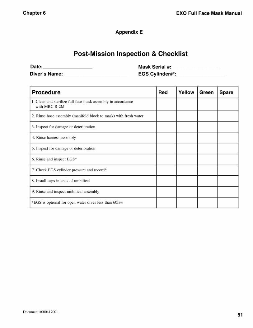
51
Chapter 6 EXO Full Face Mask Manual
Document #000417001
Appendix E
Post-Mission Inspection & Checklist
Date:__________________Diver’s Name:________________________
Mask Serial #:__________________EGS Cylinder#*:__________________
erudecorP deR wolleY neerG erapS
ecnadroccaniylbmessaksamecafllufeziliretsdnanaelC.1M2-RCRMhtiw
retawhserfhtiw)ksamotkcolbdlofinam(ylbmessaesohesniR.2
noitaroiretedroegamadroftcepsnI.3
ylbmessassenrahesniR.4
noitaroiretedroegamadroftcepsnI.5
*SGEtcepsnidnaesniR.6
*drocerdnaerusserprednilycSGEkcehC.7
lacilibmufosdnenispacllatsnI.8
ylbmessalacilibmutcepsnidnaesniR.9
wsf06nahtsselsevidretawneporoflanoitposiSGE*
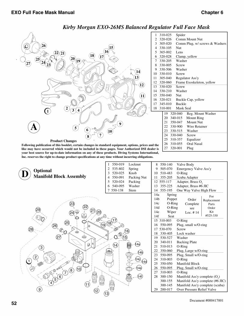
EXO Full Face Mask Manual Chapter 6
52Document #000417001
Kirby Morgan EXO-26MS Balanced Regulator Full Face Mask
Product ChangesFollowing publication of this booklet, certain changes in standard equipment, options, prices and thelike may have occurred which would not be included in these pages. Your Authorized DSI dealer isyour best source for up-to-date information on any of these products. Diving Systems International,Inc. reserves the right to change product specifications at any time without incurring obligations.
19 320-040 Reg. Mount Washer 20 340-015 Mount Ring 21 350-047 Mount Nut 22 330-900 Wire Retainer 23 330-515 Washer 24 330-040 Screw 25 310-357 Equalizer 26 310-055 Oral Nasal 27 320-001 Plug
1 310-025 Spider 2 320-026 Comm Mount Nut 3 305-020 Comm Plug, w/ screws & Washers 4 330-105 Nut 5 365-002 Lens 6 320-028 Clamp, yellow 7 330-205 Washer 8 330-005 Screw 9 330-506 Washer 10 330-010 Screw 11 305-040 Regulator Ass'y 12 320-060 Frame Exoskeleton, yellow 13 330-020 Screw 14 330-210 Washer 15 350-040 Nut 16 320-021 Buckle Cap, yellow 17 345-010 Buckle 18 310-001 Mask Seal
OptionalManifold Block Assembly
1 550-019 Locknut 2 535-802 Spring 3 520-025 Knob 4 550-091 Packing Nut 5 520-024 Packing 6 540-095 Washer 7 550-138 Stem
8 550-140 Valve Body 9 505-070 Emergency Valve Ass'y 10 510-483 O-Ring 11 355-205 Scuba Adapter 12 555-117 Adapter, Brass O
2
13 355-225 Adapter, Brass #6 JIC 14 555-195 One Way Valve High Flow 14a Spring 14b Poppet 14c O-Ring 14d O-Ring 14e Wiper 14f Seat 15 310-003 O-Ring 16 550-095 Plug, small w/O-ring 17 530-070 Screw 18 330-405 Lock washer 19 530-527 Washer 20 340-011 Backing Plate 21 510-013 O-Ring 22 350-060 Plug, Large w/O-ring 23 550-095 Plug, Small w/O-ring 24 310-003 O-Ring 25 350-050 Manifold Block 26 550-095 Plug, Small w/O-ring 27 310-003 O-Ring 28 300-150 Manifold Ass'y complete (O
2)
300-155 Manifold Ass'y complete (#6 JIC) 300-145 Manifold Ass'y complete (scuba) 29 200-017 Over Pressure Relief Valve
OrderComplete
seeLoc. # 14
ForReplacement
PartsOrder
Kit#525-330
D
12
3 4
56
78
10
9
11
12
13
14
15
16
1718
19
26
2122
2324
25
27
20
12 3 4
5 678
9
10
13
14
1516
171819
202122
2425
26
2327
A
11
12
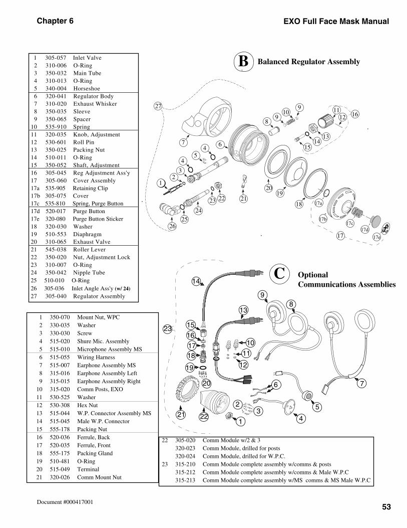
53
Chapter 6 EXO Full Face Mask Manual
Document #000417001
Balanced Regulator Assembly 1 305-057 Inlet Valve 2 310-006 O-Ring 3 350-032 Main Tube 4 310-013 O-Ring 5 340-004 Horseshoe 6 320-041 Regulator Body 7 310-020 Exhaust Whisker 8 350-035 Sleeve 9 350-065 Spacer10 535-910 Spring11 320-035 Knob, Adjustment12 530-601 Roll Pin13 350-025 Packing Nut14 510-011 O-Ring15 350-052 Shaft, Adjustment16 305-045 Reg Adjustment Ass'y17 305-060 Cover Assembly17a 535-905 Retaining Clip17b 305-075 Cover17c 535-810 Spring, Purge Button17d 520-017 Purge Button17e 320-080 Purge Button Sticker18 320-030 Washer19 510-553 Diaphragm20 310-065 Exhaust Valve21 545-038 Roller Lever22 350-020 Nut, Adjustment Lock23 310-007 O-Ring24 350-042 Nipple Tube25 510-010 O-Ring26 305-036 Inlet Angle Ass'y (w/ 24)
27 305-040 Regulator Assembly
B
17a
17c17d
17b
17e17
12
3
45
467
89
109 11
12
1314
15
16
18
1920
212223
24
2526
27
B
1 350-070 Mount Nut, WPC 2 330-035 Washer 3 330-030 Screw 4 515-020 Shure Mic. Assembly 5 515-010 Microphone Assembly MS 6 515-055 Wiring Harness 7 515-007 Earphone Assembly MS 8 315-016 Earphone Assembly Left 9 315-015 Earphone Assembly Right 10 315-020 Comm Posts, EXO 11 530-525 Washer 12 530-308 Hex Nut 13 515-044 W.P. Connector Assembly MS 14 515-045 Male W.P. Connector 15 555-178 Packing Nut 16 520-036 Ferrule, Back 17 520-035 Ferrule, Front 18 555-175 Packing Gland 19 510-481 O-Ring 20 515-049 Terminal 21 320-026 Comm Mount Nut
22 305-020 Comm Module w/2 & 3 320-023 Comm Module, drilled for posts 320-024 Comm Module, drilled for W.P.C. 23 315-210 Comm Module complete assembly w/comms & posts 315-212 Comm Module complete assembly w/comms & Male W.P.C 315-213 Comm Module complete assembly w/MS comms & MS Male W.P.C
OptionalCommunications Assemblies
CD
ivin
gS
yste
ms
International Santa BarbaraC
AU
SA
Div
ing
Sys
tem
s
International Santa BarbaraC
AU
SA
1
23
4
5
6 7
89
13
10
11
12
14
15
16
1718
19
20
21 22
23