Embed Size (px)
Citation preview
JSC-25665
/T ’/ ‘A’ /// i *
Cargo Systems Manual: t Heat Pipe Performance
(HPP) 1
i / 7 73 t - 33
STS-66
Operations Division Payload Operations Branch a Basic June 1994
( N A S A - TM- 10 9784 1 HANUAL: HEAT P I P E P E R F O R M A N C E (HPP) S T S - 6 6 ( N A S A . Johnson S p a c e Center) 3 3 p
CARGO SY S TE M S
National Aeronautics and Space Administration Lyndon B. Johnson Space Center e Houston, Texas
N 9 4 - 3 4 7 2 0
Unc 1 as
G 3 / 6 6 0011773
https://ntrs.nasa.gov/search.jsp?R=19940030214 2018-06-12T11:58:52+00:00Z
JSC-25665
Cargo Systems Manual: Heat Pipe Performance (HPP)
STS-66
Basic
June 1994
Prepared by
R M r t Napp Book Manager
Approved by
H%d, &ached Payload Opehtions Section
NATIONAL AERONAUTICS AND SPACE ADMINISTRATION LYNDON B. JOHNSON SPACE CENTER
HOUSTON, TEXAS
JSC-25665
This document has been prepared by the Payload Operations Branch, Operations Division, Mission Operations Directorate (MOD), NASA, Lyndon B. Johnson Space Center, Houston, Texas, with editorial support from the Integrated Documentation Support Department, Hernandez Engineering, Inc., and technical support from the Space Shuttle Program, Cargo Engineering Office (TJ). The Cargo Engineering Office has reviewed the Cargo Systems Manual (CSM) to the level of detail contained herein and verified that all orbiter-to-payload avionics interfaces are accurately represented.
Comments concerning the general contents of this manual should be directed to D065/Robert Napp, 713-244-0275.
The purpose of the CSM is to provide a payload reference document for payload and shuttle flight operations personnel during shuttle mission planning, training, and flight operations. The CSM will include orbiter-to-payload interface information and payload system information (in- cluding operationally pertinent payload safety data) that is directly applicable to the MOD role in the payload mission. The CSM is an accurate source of this information for use by flight opera- tions personnel.
JSC-25665
CONTENTS Section
1 INTRODUCTION .................................................... 1.1 OBJECTIVES ....................................................... 1.2 HISTORY ........................................................... 1.3 DESCRIPTION ...................................................... 1.4 MISSION SCENARIO ................................................ 2 HEAT PIPE PERFORMANCE ......................................... 2.1 INTRODUCTION .................................................... 2.2 MECHANICAL SUPPORT AND ROTATING ASSEMBLIES ................ 2.3 INSTRUMENTATION AND CONTROL ................................. 2.4 POWER ............................................................ 3 HEAT PIPES ........................................................
Page
1-1
1-1 1-1 1-1 1-3
2-1
2-1 2-1 2-2 2-6
3-1
4 DISPLAYS AND CONTROLS ......................................... 4-1
4.1 CONTROL MODULE ................................................. 4-1 4.1.1 DISPLAY ...................................................... 4-1 4.1.2 CONTROL .................................................... 4-1
4.2 PGSC .............................................................. 4-2
Appendix
A ACRONYMS AND ABBREVIATIONS .................................. A-1
B CONFIGURATION CONTROL ........................................ B-1

. JSC-25665
TABLES
Table Page
2-1 Power requirements of HPP equipment ................................. 2-6
Figure
1-1 HPP apparatus ...................................................... 1-2
2-1 HPP apparatus (without safety shroud) ................................. 2-3 2-2 ControVmotor module ................................................ 2-4 2-3 Safety shroud envelope .............................................. 2-5 2 4 HPP control module .................................................. 2-7
3-1 Heat pipe ........................................................... 3-2 3-2 Heat pipe heater configuration ......................................... 3-3 3-3 HC1 heater configuration ............................................. 3-4 3-4 HC2 heater configuration ............................................. 3-5 3-5 HC3 heater configuration ............................................. 3-6 3-6 Heater circuit select switch ............................................ 3-7 3-7 Heat pipe storage container ........................................... 3-8 3-8 Heat pipe storage container tray ....................................... 3-9
DRAWINGS
Drawing
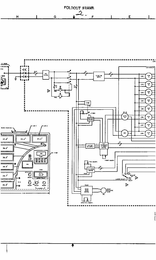
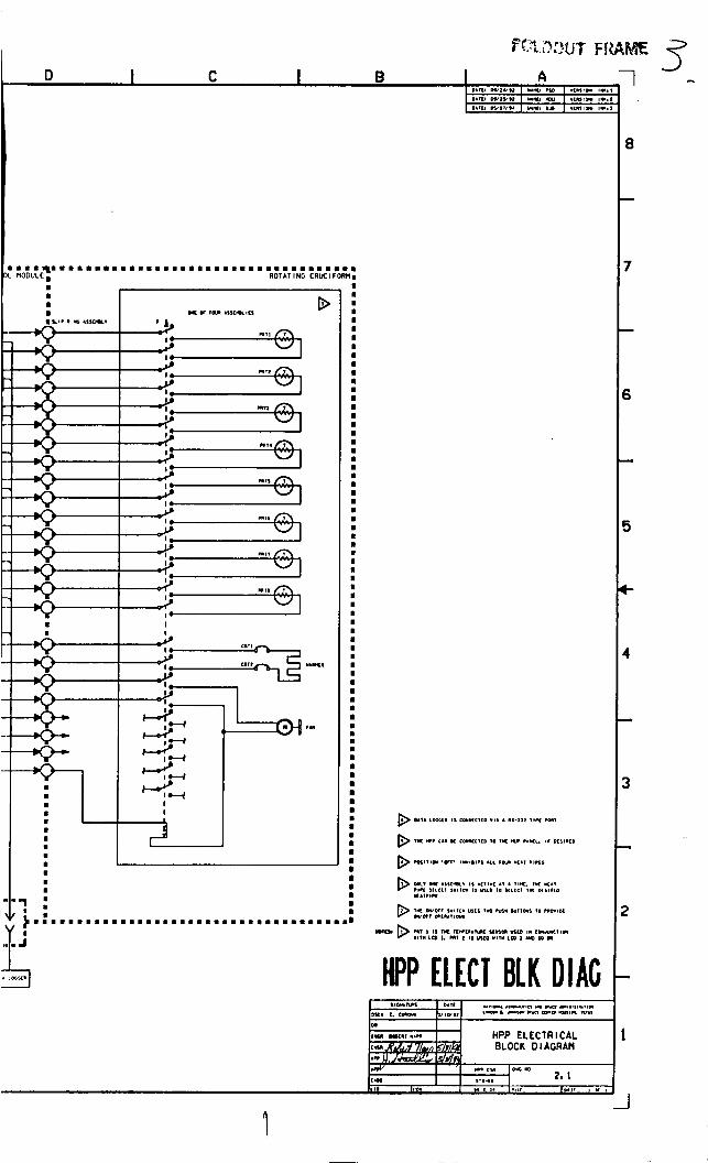
2.1 HPP ELECTRICAL BLOCK DIAGRAM ................................. 2-9
vi
JSC-25665
SECTION 1 INTRODUCTION
1.1 OBJECTIVES
The primary objectives of the Heat Pipe Performance (HPP) are to obtain quantitative data on the thermal performance of heat pipes in a microgravity environment. This information will in- crease understanding of the behavior of heat pipes in space and be useful for application to de- sign improvements in heat pipes and associated systems.
The purpose of HPP-2 is to establish a complete on- and zero-g database for axial groove heat pipes. This data will be used to update and correlate data generated from a heat pipe de- sign computer program called Grooved Analysis Program (GAP). The program predicts maxi- mum heat transport capacity vs. operating temperature for axially grooved heat pipes. The HPP-2 objectives are:
Determine heat transport capacity and conductance for opedclosed grooved heat pipes and different Freon volumes (nominal, under, and overcharged) using a uniform heat load
Determine heat transport capacity and conductance for single/multiple evaporators using asymmetric heat loads
Obtain precise static, spin, and rewicking data points for undercharged pipes
Investigate heat flux limits (asymmetric heat loads)
Determine effects of positive body force on thermal performance
1.2 HISTORY
Much of the HPP hardware design is an outgrowth of the Hughes Fluid Dynamics Experiment (FDE) developed before 1986. Experiments were conducted on the KC-135. The FDE under- went the space shuttle flight certification process in use at the time. The experience gained has been used to improve HPP, making the experiment safer and easier to perform. HPP flew for the first time on STS-52 in October 1992.
0
1.3 DESCRIPTION
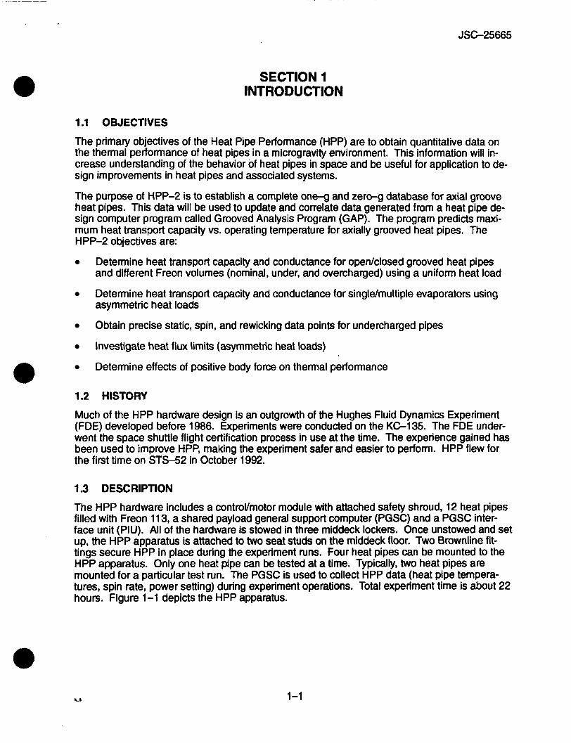
The HPP hardware includes a controVmotor module with attached safety shroud, 12 heat pipes filled with Freon 11 3, a shared payload general support computer (PGSC) and a PGSC inter- face unit (PIU). All of the hardware is stowed in three middeck lockers. Once unstowed and set up, the HPP apparatus is attached to two seat studs on the middeck floor. Two Brownline fit- tings secure HPP in place during the experiment runs. Four heat pipes can be mounted to the HPP apparatus. Only one heat pipe can be tested at a time. Typically, two heat pipes are mounted for a particular test run. The PGSC is used to collect HPP data (heat pipe tempera- tures, spin rate, power setting) during experiment operations. Total experiment time is about 22 hours. Figure 1-1 depicts the HPP apparatus.
1-1
JSC-25665
L
. . . . . . . . . . . .*.:.:.:.:. :.:.:.:.:.: ..-*.:.:.:. . . -.:.:.:.:.: . . . . . . . . . . . . . . . , .
. . . . . . . ...:.: '.'.'.'.:. . . . . . :.:.:::::: ......... . . . . . . . '.I.:.:.:. . . . . . .
Y
CL SHROUD TOPS
VENTED ALUMINUM SHROUD SIDES
. . . . . . . ......... .......... .......... .......... . . . .:.:.:. . . . . . . . . . . . :::i:;:::: . .
.......... .......
. . . . . . . . . . . -...:.:.:. . .:.:.:.: *.*.*.:.:. .... ::::::-:*: . . .....
I l l
Figure 1-1. HPP apparatus
T 11 4.3" I
1 -2
JSC-25665
1.4 MISSION SCENARIO
There are three types of experiment tests: static, spin, and rewickina. The static test is Der- 0 formed with the heat pipes in a static (non-rotating) configuration. Eghteen tests are planned. Performance of the different heat pipe designs is tested with different heat loads on the evapo- rator end. Static tests require about 13.5 total hours to perform.
The spin tests are performed with the heat pipes in a rotating configuration. The heat pipes are attached in the same manner as in the static tests. Different spin rates are selected to cause the heat pipes to rotate similar to a merry-go-round. The Freon inside the pipe is forced out to the evaporator end. Performance of heat pipe designs using different heat loads and spin rates is measured. Fourteen spin tests are planned. Total test time is about 7 hours.
Rewicking tests begin by spinning the heat pipes. After about 10 minutes, the spin rate is reduced to zero. The time for the fluid to rewick under different heat loads is measured. Three rewicking tests are performed. Total testing time is about 1 hour.
1-3
JSC-25665
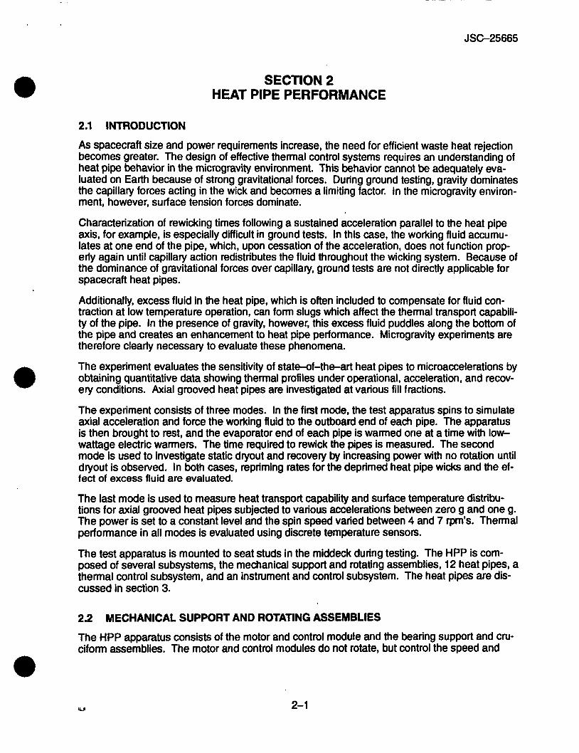
SECTION 2 HEAT PIPE PERFORMANCE
2.1 INTRODUCTION
As spacecraft size and power requirements increase, the need for efficient waste heat rejection becomes greater. The design of effective thermal control systems requires an understanding of heat pipe behavior in the microgravity environment. This behavior cannot be adequately eva- luated on Earth because of strong gravitational forces. During ground testing, gravity dominates the capillary forces acting in the wick and becomes a limiting factor. In the microgravity environ- ment, however, surface tension forces dominate.
Characterization of rewicking times following a sustained acceleration parallel to the heat pipe axis, for example, is especially difficult in ground tests. In this case, the working fluid accumu- lates at one end of the pipe, which, upon cessation of the acceleration, does not function prop- erly again until capillary action redistributes the fluid throughout the wicking system. Because of the dominance of gravitational forces over capillary, ground tests are not directly applicable for spacecraft heat pipes.
Additionally, excess fluid in the heat pipe, which is often included to compensate for fluid con- traction at low temperature operation, can form slugs which affect the thermal transport capabili- ty of the pipe. In the presence of gravity, however, this excess fluid puddles along the bottom of the pipe and creates an enhancement to heat pipe performance. Microgravity experiments are therefore clearly necessary to evaluate these phenomena.
The experiment evaluates the sensitivity of state-of-the-art heat pipes to microaccelerations by obtaining quantitative data showing thermal profiles under operational, acceleration, and recov- ery conditions. Axial grooved heat pipes are investigated at various fill fractions.
The experiment consists of three modes. In the first mode, the test apparatus spins to simulate axial acceleration and force the working fluid to the outboard end of each pipe. The apparatus is then brought to rest, and the evaporator end of each pipe is warmed one at a time with low- wattage electric warmers. The time required to rewick the pipes is measured. The second mode is used to investigate static dryout and recovery by increasing power with no rotation until dryout is observed. In both cases, repriming rates for the deprimed heat pipe wicks and the ef- fect of excess fluid are evaluated.
The last mode is used to measure heat transport capability and surface temperature distribu- tions for axial grooved heat pipes subjected to various accelerations between zero g and one g. The power is set to a constant level and the spin speed varied between 4 and 7 rpm’s. Thermal performance in all modes is evaluated using discrete temperature sensors.
The test apparatus is mounted to seat studs in the middeck during testing. The HPP is com- posed of several subsystems, the mechanical support and rotating assemblies, 12 heat pipes, a thermal control subsystem, and an instrument and control subsystem. The heat pipes are dis- cussed in section 3.
2.2
The HPP apparatus consists of the motor and control module and the bearing support and cru- ciform assemblies. The motor and control modules do not rotate, but control the speed and
MECHANICAL SUPPORT AND ROTATING ASSEMBLIES
2-1
JSC-25665
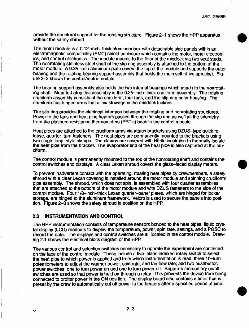
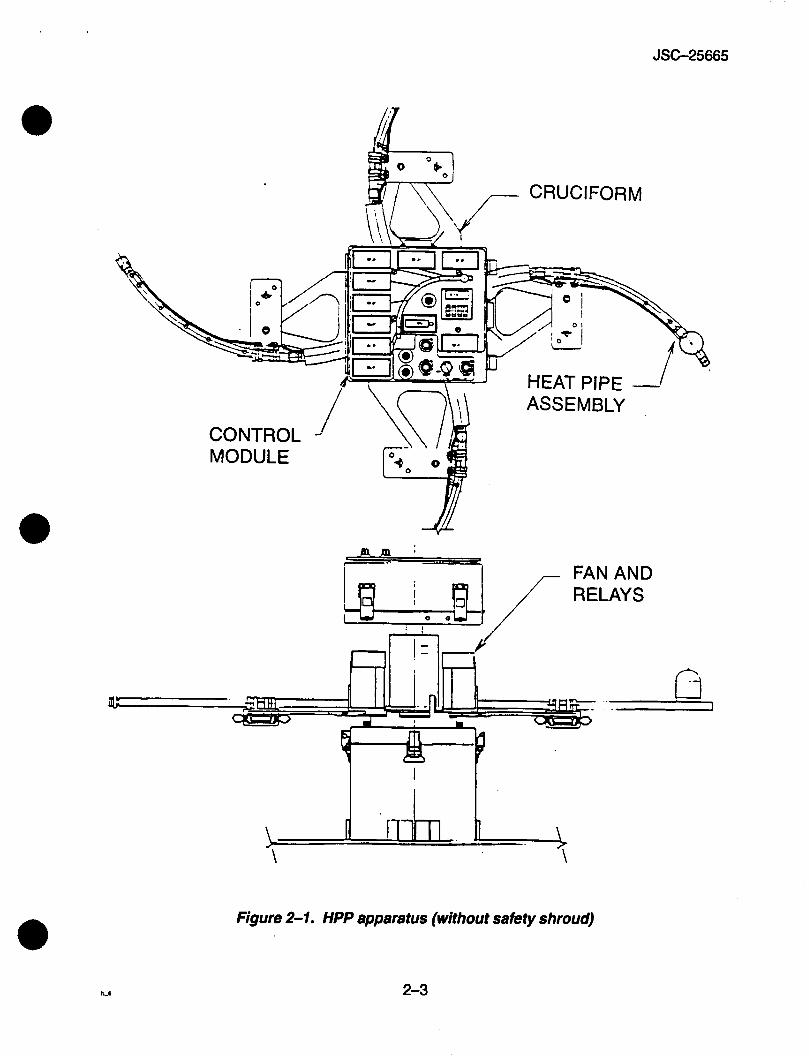
provide the structural support for the rotating structure. Figure 2-1 shows the HPP apparatus without the safety shroud.
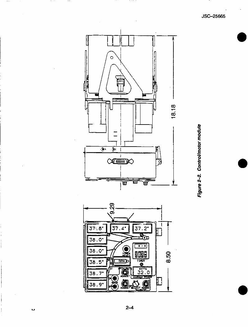
The motor module is a 0.12-inch-thick aluminum box with detachable side panels within an electromagnetic compatibility (EMC) shield enclosure which contains the motor, motor electron- ics, and control electronics. The module mounts to the floor of the middeck via two seat studs. The nonrotating stainless steel shaft of the slip ring assembly is attached to the bottom of the motor module. A 0.25-inch aluminum plate covers the top of the module and supports the outer bearing and the rotating bearing support assembly that holds the main self-drive sprocket. Fig- ure 2-2 shows the controVmotor module.
The bearing support assembly also holds the two internal bearings which attach to the nonrotat- ing shaft. Mounted atop this assembly is the 0.25-inch-thick cruciform assembly. The rotating cruciform assembly consists of the cruciform, four fans, and the slip ring outer housing. The cruciform has hinged arms that allow stowage in the middeck lockers.
The slip ring provides the electrical interface between the rotating and nonrotating structures. Power to the fans and heat pipe heaters passes through the slip ring as well as the telemetry from the platinum resistance thermometers (PRT's) back to the control module.
Heat pipes are attached to the cruciform arms via attach brackets using DZUS-type quick re- lease, quarter-turn fasteners. The heat pipes are permanently mounted to the brackets using two single loop-style clamps. The clamps are covered with Nitrile insulation to thermally isolate the heat pipe from the bracket. The evaporator end of the heat pipe is also captured at the cru- ciform.
The control module is permanently mounted to the top of the nonrotating shaft and contains the control switches and displays. A clear Lexan shroud covers the glass-faced display meters.
To prevent inadvertent contact with the operating, rotating heat pipes by crewmembers, a safety shroud with a clear Lexan covering is installed around the motor module and spinning cruciform/ pipe assembly. The shroud, which does not spin, is assembled with four quarter assemblies that are attached to the bottom of the motor module and with DZUS fasteners to the side of the control module. Four l/&inch-thick Lexan quarter-panel plates, which are hinged for locker storage, are hinged to the aluminum framework. Velcro is used to secure the panels into posi- tion. Figure 2-3 shows the safety shroud in position on the HPP.
2.3 INSTRUMENTATION AND CONTROL
The HPP instrumentation consists of temperature sensors bonded to the heat pipes, liquid crys- tal display (LCD) readouts to display the temperature, power, spin rate, settings, and a PGSC to record the data. The displays and control switches are all located in the control module. Draw- ing 2.1 shows the electrical block diagram of the HPP.
The various control and selection switches necessary to operate the experiment are contained on the face of the control module. These include a five-place indexed rotary switch to select the heat pipe to which power is applied and from which instrumentation is read; three 10-turn potentiometers to adjust the warmer power, spin rate, and fan flow rate; and two pushbutton power switches, one to tum power on and one to turn power off. Separate momentary on/off switches are used so that power is held on through a relay. This prevents the device from being connected to orbiter power in the ON position. The display board also contains a timer that is preset by the crew to automatically cut off power to the heaters after a specified period of time.
2-2
JSC-25665
Figure 2-1. HPP apparatus (without safety shroud)
2-3
JSC-25665

JSC-25665
I
2-5
JSC-25665
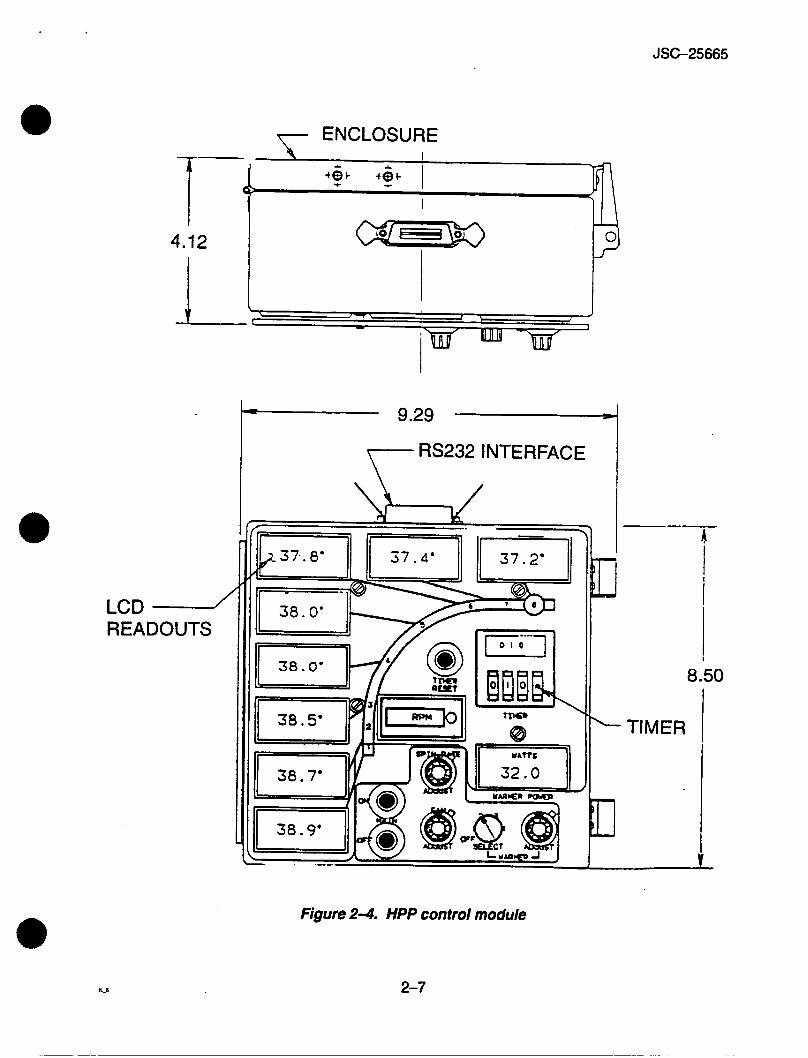
A lO-meter LCD display is also part of the control module. Eight of the meters read out the temperature indicated by the PRT's on the selected pipe. The two other meters output a read- ing of the amount of power being input into the heat pipe warmer and the spin rate of the heat pipe assembly. Because the LCD meters have glass faces, a clear Lexan shield covers the entire display portion of the control module. Figure 2-4 shows the LCDs and controls on the control module.
A PIU is connected via an RS-232C interface to the side of the control module. The PIU con- nects to a PGSC through an RS-232C, which records the outputs of the PRT's, the spin, and power settings at a rate of TBD seconds.
2.4 POWER
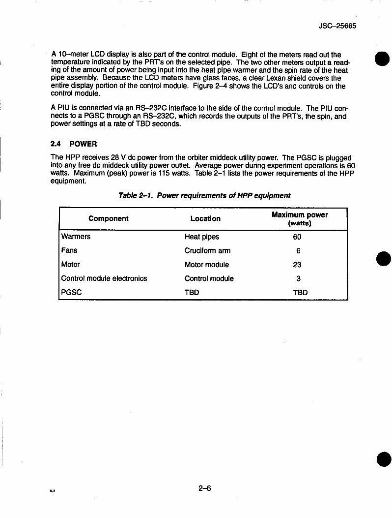
The HPP receives 28 V dc power from the orbiter middeck utility power. The PGSC is plugged into any free dc middeck utility power outlet. Average power during experiment operations is 60 watts. Maximum (peak) power is 115 watts. Table 2-1 lists the power requirements of the HPP equipment.
Table 2-1. Power requirements of HPP equipment
Component Location I Maximum power (watts)
Warmers Heat pipes
Fans Cruciform arm
Motor Motor module
Control module electronics Control module
PGSC TBD
60
6
23
3
TBD
2-6
JSC-25665
7 ENCLOSURE I
7-- I ' *
4.12 ' I t3
LCD - READOUTS
1 9.29 
RS232 INTERFACE
4
11-
P 8.50
TIMER
Figure 2-4. HPP control module
2-7
J SC-25665
SECTION 3 HEAT PIPES
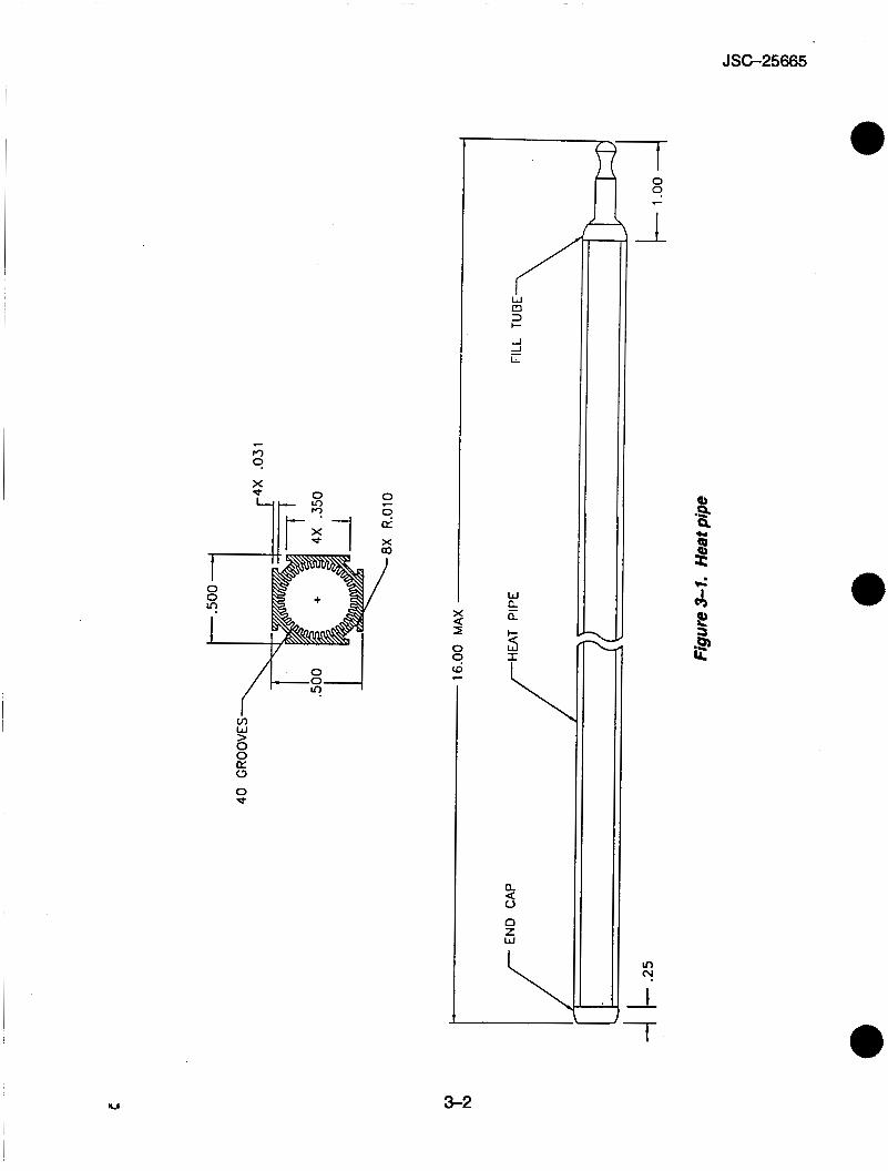
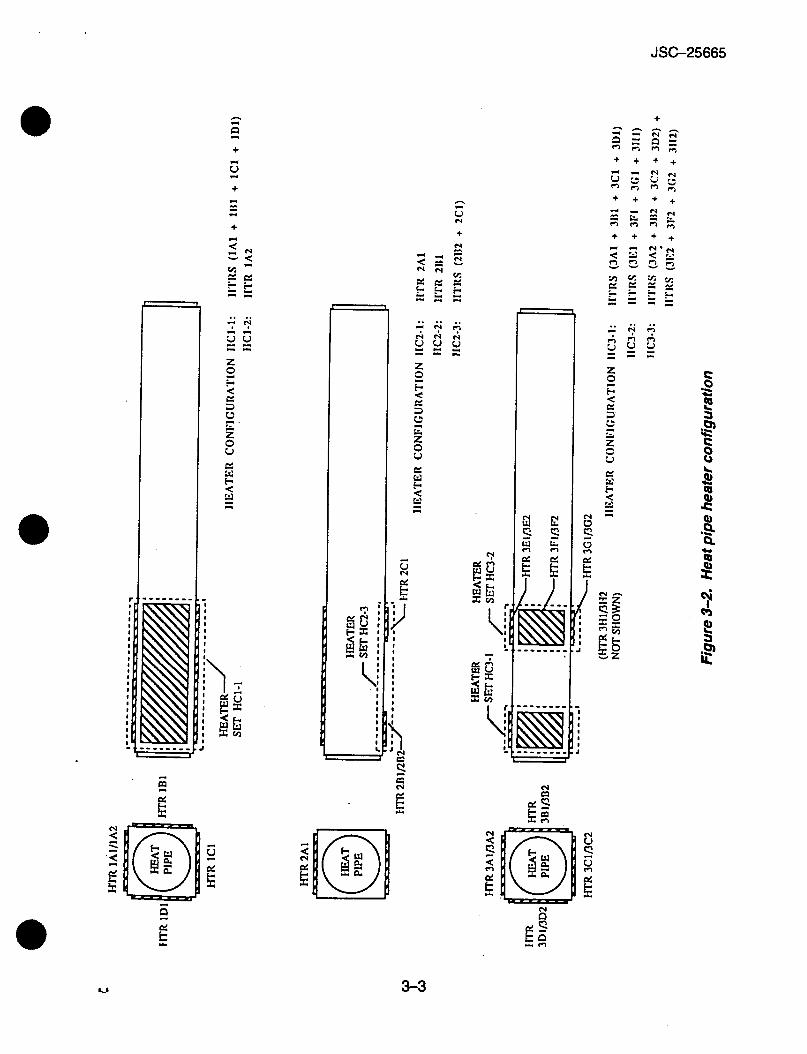
Twelve axial grooved constant conductance heat pipes are flown with the HPP apparatus. Ten of the twelve are to be used during experiment operations. The remaining two pipes are flight spares. Freon 113 is used as the working fluid (approximately 8.5 grams). Each pipe is 16 in. long with a 0.5 in. by 0.5 in. cross section. The heat pipes are made from type 6063-T6 alumi- num. See figure 3-1.
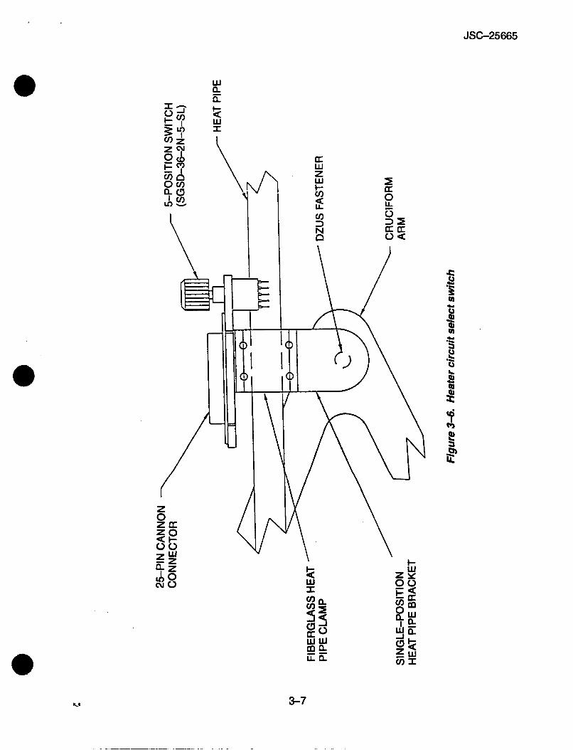
Heaters are located on each pipe to apply different heat loads. There are three primary heat pipe heater configurations. Each heater is a dual-element, Kapton-insulated, thin-foil Minco heater. There are three heater configurations. See figure 3-2. Each pipe has one of the three heater configurations attached to it. In addition, each heater configuration can have up to three heater circuit arrangements. See figures 3-3, 3-4, and 35. The different heater circuits can be selected with a rotary switch located on each heat pipe. See figure 3-6. Using the warmer circuit select knob, different heat loads can be applied. Heat can be applied uniformly around the pipe or from one side. The amount of power applied to the heaters can be varied from a knob on the control module. Input power ranges from 0 to 60 W.
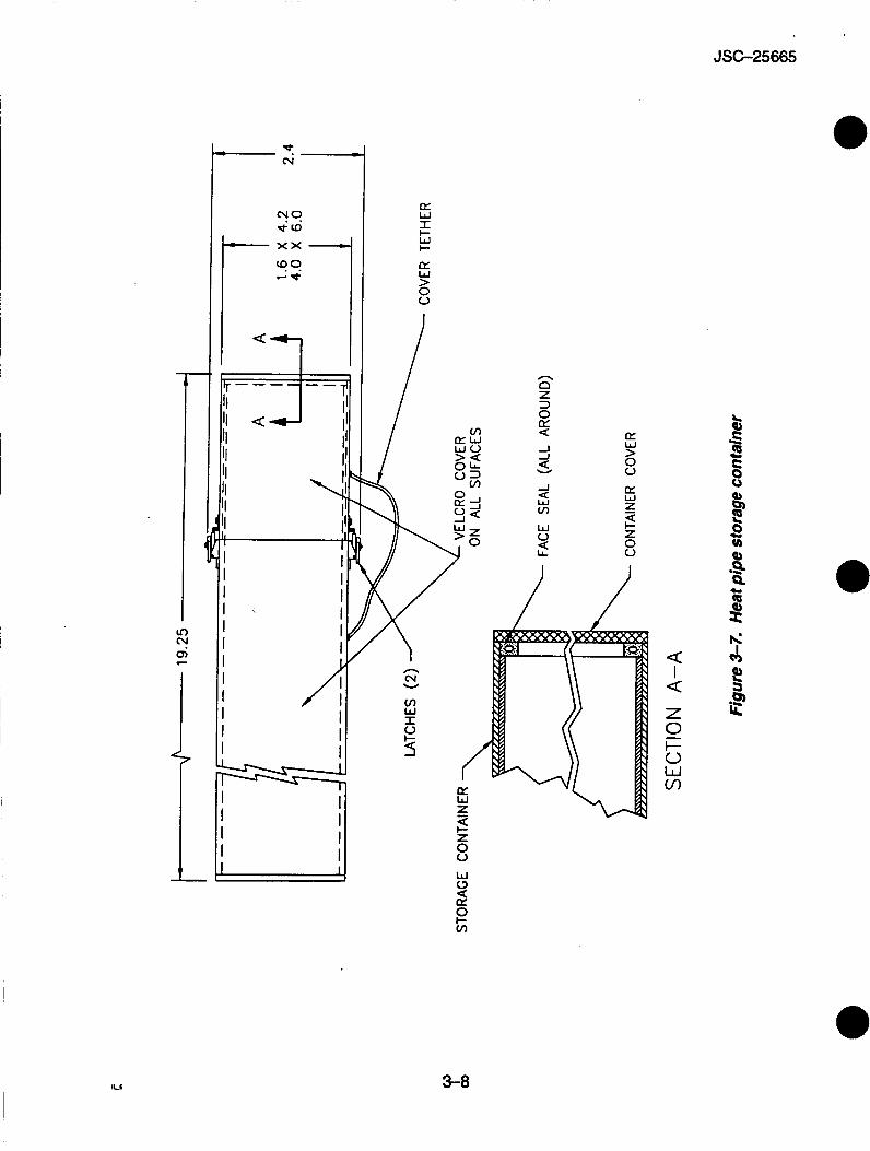
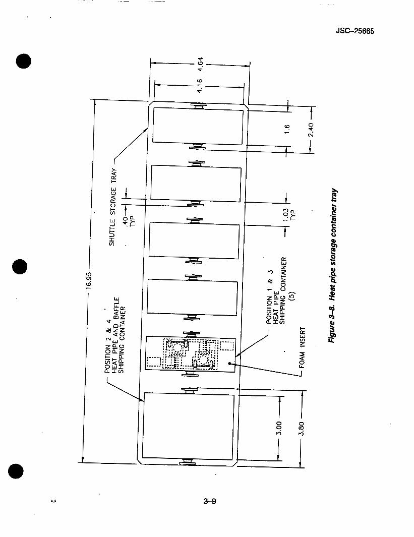
For safety, six storage containers house the heat pipes when they are not attached to the HPP apparatus. Each storage container holds two heat pipes. The storage boxes are doubly con- tained to protect against the inadvertent leakage of Freon. Nominally, only two heat pipes will be out at any one time. The six storage containers are contained in a single middeck locker. See figures 3-7 and 3-8.
A fan mounted to each arm of the rotating cruciform support provides cooling airflow to the operating heat pipe. The fans increase the convective heat transfer between the pipe and the middeck air to allow the experiment to operate at safe temperatures. Temperature range for a heat pipe will vary between 40° and 85" C. Each fan has a dual-position baffle design used to regulate the amount of air flow over the heat pipe. A knob on the control module adjusts the speed of the fan.
3-1
r, 9 X
W > 0 0 CY 0
0 d.
2 I 0
(D 9 c
W
Q a
Q
u 0 z W
a
JSC-25665
0 9
f
3-2
JSC-25665
e
'I N
c s 4 r4
[;1 r %
E I
+ + + +
+ + + +
8 'b
3-3
JSC-25665
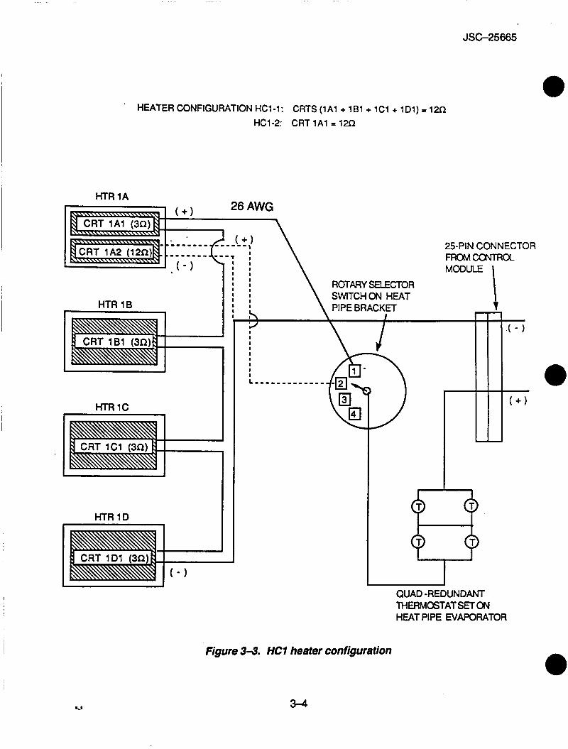
HEATER CONFIGURATION HC1-1: CRTS (1Al + 1B1 + 1C1 + 1D1) p 12R
HC1-2: CRT 1Al = 12cz
HTR 1A
ROTARY SELECTOR SWITCHON HEAT
HTR 1B
QUAD -REDUNDANT THERMOSTATSETON HEAT PIPE EVAPORATOR
Figure 3-3. HCl heater configuration
3-4
JSC-25665
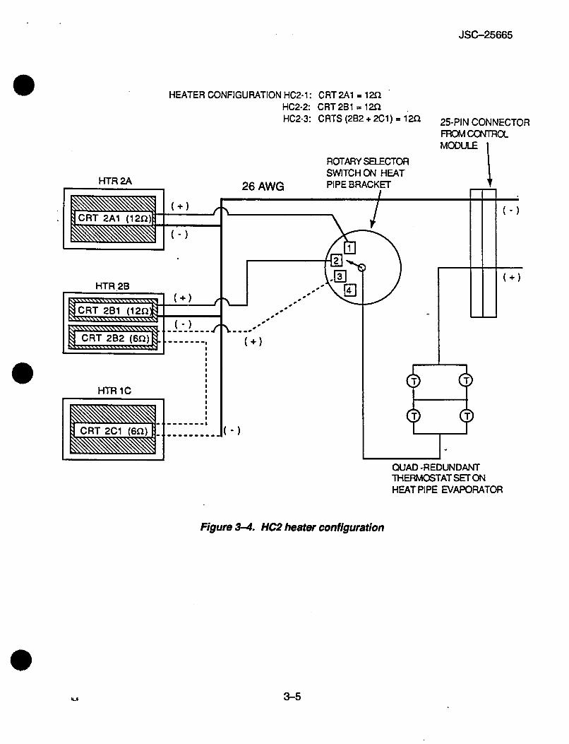
HEATER CONFIGURATION HC2-1: CRT 2 A 1 = lm
HTR 2A
J , .
HTR 28
HTR 1C 9 3 ~~
QUAD -REDUNDANT THERMOSTATSFION HEAT PIPE EVAPORATOR
Figure 3-4. HC2 heater configuration
w 3-5
JSC-25665
-
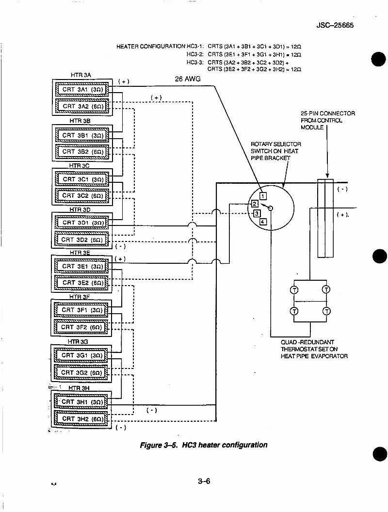
HEATER CONFIGURATION HC3-1: HC3-2: HC3-3:
CRTS (3A1 + 381 + 3C1 + 301) P 12R CRTS (3E1 + 3F1 + 3G1 + 3H1) = 12R CRTS (3A2 + 382 + 3C2 + 3D2) + CRTS (3E2 + 3F2 + 3G2 + 3H2) = 12R
25-PIN CONNECTOR
HTR 38 I !
t HTR 3C I I I I I I
- - a
- - 7 I
I I I I I I I I I I I I I I I I I I I I I I I I I I
HTR 3E I I
f I I 1
7 I I I I I I I I I I
- - - a
.--
HTR 3G I : I I I I I
L
FROMCONTROL: MODULE
ROTARY SELECTOR \ SWITCHON HEAT
QUAD -REDUNDANT THERMOSTATSETON HEAT PIPE EVAPORATOR
I& ... . , ' ( - 1
Figure 3-5. HC3 heater configuration
3-6
W n h t W I
JSC-25665
3-7
JSC-25665
W I t- W !-
a: W
0 & I
4 I 4 Z 0 -
3-8
JSC-25665
In (D o! c
E r 3
m
W
I I
I L
0
hl '9 t c
t
c h:
z W v,
3-9
JSC-25665
Switch/lndicator
MAIN ON pb MAIN OFF pb WARMER SELECT rot sw
WARMER ADJUST knob
FAN ADJUST knob
SPIN RATE ADJUST knob
TIMER pbs
TIMER RESET pb
SECTION 4 DISPLAYS AND CONTROLS
Function
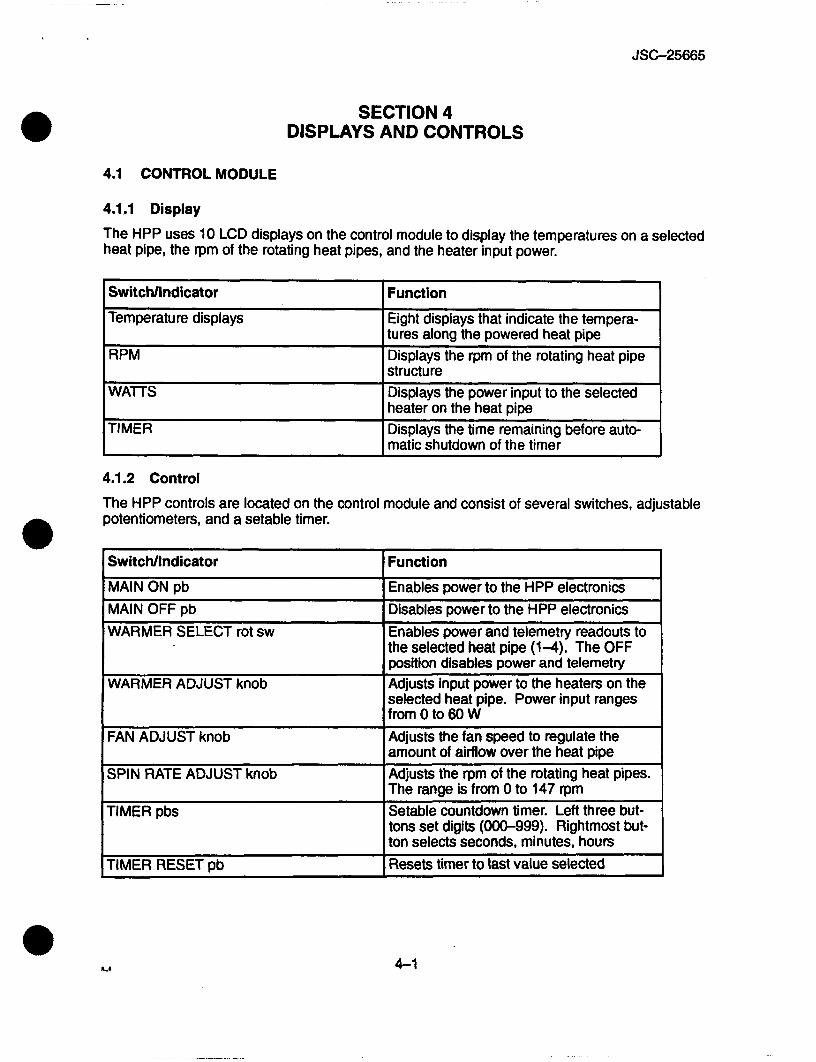
Enables power to the HPP electronics Disables power to the HPP electronics Enables power and telemetry readouts to the selected heat pipe (1-4). The OFF position disables power and telemetry Adjusts input power to the heaters on the selected heat pipe. Power input ranges from 0 to 60 W Adjusts the fan speed to regulate the amount of airflow over the heat pipe Adjusts the rprn of the rotating heat pipes. The range is from 0 to 147 rpm Setable countdown timer. Left three but- tons set digits (OW999). Rightmost but- ton selects seconds, minutes, hours Resets timer to last value selected
4.1 CONTROL MODULE
4.1.1 Display
The HPP uses 10 LCD displays on the control module to display the temperatures on a selected heat pipe, the rprn of the rotating heat pipes, and the heater input power.
Switchllndicator
Temperature displays
I ir IVI
WATTS
Function
Eight displays that indicate the tempera- tures along the powered heat pipe Displays the rpm of the rotating heat pipe structure
1 Displays the power input to the selected ' heater on the heat pipe Displays the time remaining before auto-
1 matic shutdown of the timer ~ ~ ~ ~~
4.1.2 Control
The HPP controls are located on the control module and consist of several switches, adjustable potentiometers, and a setable timer.
4-1
JSC-25665
4.2 PGSC An orbiter shared PGSC is used to acquire, display, and store HPP data. A PIU is connected between the HPP control module and the PGSC. Heat pipe temperatures, spin rate, and heater power are displayed on a customer-generated computer program. The menu driven data acquisition software retrieves data from PIU at fixed intervals through RS-232 serial port. There are no control functions associated with the software, only display capabilities.
Prior to experiment operations, the software must be loaded from floppy disks. At the comple- tion of experiment operations, the data files are transferred from the PGSC hard drive to floppy disks.
Daily portable audio data modem (PADM) data dumps are performed of the most recent experi- ment data to allow ground personnel to track heat pipe test results and anomalies.
4-2
JSC-25665
CSM
EMC
FDE
GAP
HPP
JSC
LCD
MOD
PADM Pb PGSC PI u PRT
rot sw
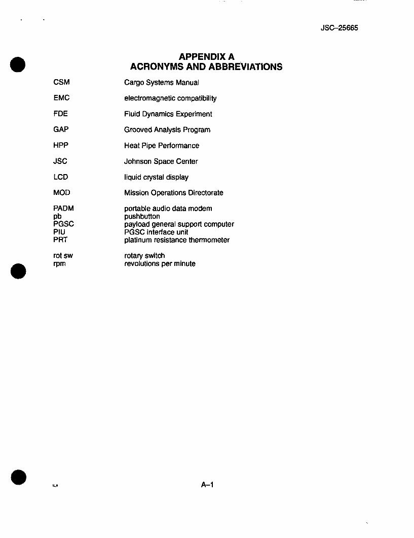
APPENDIX A ACRONYMS AND ABBREVIATIONS
Cargo Systems Manual
electromagnetic compatibility
Fluid Dynamics Experiment
Grooved Analysis Program
Heat Pipe Performance
Johnson Space Center
liquid crystal display
Mission Operations Directorate
portable audio data modem push button payload general support computer PGSC interface unit platinum resistance thermometer
rotary switch revolutions per minute

JSC-25665
APPENDIX B CONFIGURATION CONTROL
B.l INTRODUCTION
8.1.1 Purpose
The purpose of this appendix is to delineate configuration control procedures for the Cargo Systems Manual (CSM). This will ensure the proper coordination of changes and provide a record of proposed changes, rationale, and disposition.
8.2 CONFIGURATION CONTROL PROCEDURE
8.2.1 Submission of Changes
Proposed changes are solicited from any individual or any organization having a valid input. Changes should be submitted to the CSM book manager at mail code D06, NASNJohnson Space Center, Houston, Texas 77058.
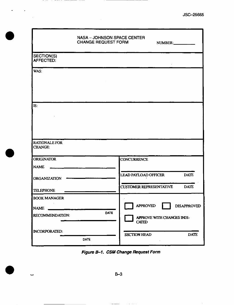
Individuals desiring to submit a change should complete all applicable items on the Change Request Form (fig. B-1). This form should be typed or neatly printed. Additional pages may be used if the space provided is not adequate. The original completed form should then be forwarded to the CSM book manager.
8.2.2 Disposition of Changes
The CSM book manager will obtain formal concurrence and comments from the necessary personnel, including customer representatives. All proposed modifications to the CR will be coordinated with all necessary personnel prior to disposition.
Upon obtaining the required concurrences, the CSM book manager will present the proposed change to the appropriate section head for final disposition.
A copy of all dispositioned CR’s will be retained by the CSM book manager for future reference. A courtesy copy of all approved CR’s will be sent to ZCOUJ. Woodall, ZCOl/S. Snipes, and TJUM. Hollman.
@
8.3 CSM REVISIONWPCN’S
6.3.1 Development
The CSM book manager will compile all approved changes and any typographical errors and incorporate them into a revision or PCN to the document.
Pen and ink changes may be used to correct typographical errors if there are no other changes on the page concerned.
El

JSC-25665
8.3.2 Approval
Any revisiondPCN's to the document will be approved by the appropriate section head. RevisiondPCN's to the final versions will also be approved by the chief of the Cargo Engineering Off ice.
6.3.3 Publication
RevisiondPCN's will be made on an as-required basis. Revisions/PCN's will be printed and distributed to the standard distribution list.
5 2
JSC-25665
NASA - JOHNSON SPACE CENTER CHANGE REQUEST FORM NUMBER
SECTION(S) AFFECTED:
WAS :
[S :
RATIONALE FOR CHANGE
DRIGINATOR
NAME
IELEPHONE
BOOK MANAGER
HAME
RECOMMENDATION DATE
[ N c o R m R A m :
DATE
lONCURRENCE
&AD PAnOADOFFICER DATE
JUSTOMER REPRESENTATIVE DATE
0 APPROVED 0 DISAPPROVED
APPR0vEwTrHc"GEsINDI-
SECTIONHEAD DATE
Figure 8-1. CSM Change Request Form
8-3
e r
*
L I K I J I I I
V l E Y 8-8
FOLDOUT F R A M A
H I G + & * F I E I
I I I I I I I 8 8 8 8 8 8 8 8 8 8 8 8 8 8 8 8 8 8 8 8 8 ~
I I I I I I I I I I I I I I I I
I I I I I I I I I I 8 m e I I I I I I I I
I I I I I 8 I I 8
I
r i m
I
L I., m o I."""
JT==
I t
1 J
V v) 3
B