Embed Size (px)
Citation preview
THE CITY AND BOROUGH OF JUNEAUAUKE BAY WASTEWATER TREATMENT PLANT
Permit No.: AKG572000
Operations and Maintenance Plan
Prepared by:City and Borough of Juneau
Department of Engineering and Public WorksUtilities Division-Wastewater
2009 Radcliffe RoadJuneau, AK 99801
Revisions:May 2016
ABTP Operations and Maintenance Plan
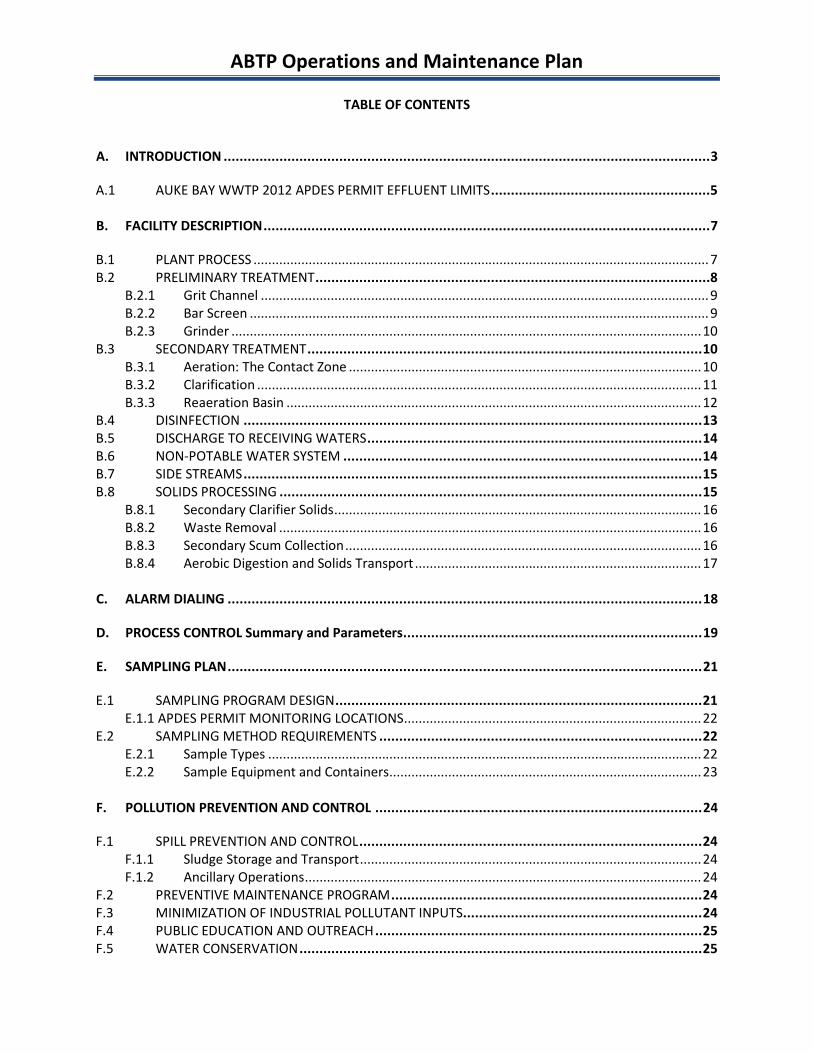
TABLE OF CONTENTS
A. INTRODUCTION ..........................................................................................................................3
A.1 AUKE BAY WWTP 2012 APDES PERMIT EFFLUENT LIMITS.......................................................5
B. FACILITY DESCRIPTION................................................................................................................7
B.1 PLANT PROCESS ............................................................................................................................7B.2 PRELIMINARY TREATMENT...................................................................................................8
B.2.1 Grit Channel ..........................................................................................................................9B.2.2 Bar Screen .............................................................................................................................9B.2.3 Grinder ................................................................................................................................10
B.3 SECONDARY TREATMENT...................................................................................................10B.3.1 Aeration: The Contact Zone ................................................................................................10B.3.2 Clarification .........................................................................................................................11B.3.3 Reaeration Basin .................................................................................................................12
B.4 DISINFECTION ...................................................................................................................13B.5 DISCHARGE TO RECEIVING WATERS....................................................................................14B.6 NON-POTABLE WATER SYSTEM ..........................................................................................14B.7 SIDE STREAMS ...................................................................................................................15B.8 SOLIDS PROCESSING ..........................................................................................................15
B.8.1 Secondary Clarifier Solids....................................................................................................16B.8.2 Waste Removal ...................................................................................................................16B.8.3 Secondary Scum Collection.................................................................................................16B.8.4 Aerobic Digestion and Solids Transport ..............................................................................17
C. ALARM DIALING .......................................................................................................................18
D. PROCESS CONTROL Summary and Parameters...........................................................................19
E. SAMPLING PLAN.......................................................................................................................21
E.1 SAMPLING PROGRAM DESIGN............................................................................................21E.1.1 APDES PERMIT MONITORING LOCATIONS.................................................................................22
E.2 SAMPLING METHOD REQUIREMENTS .................................................................................22E.2.1 Sample Types ......................................................................................................................22E.2.2 Sample Equipment and Containers.....................................................................................23
F. POLLUTION PREVENTION AND CONTROL ..................................................................................24
F.1 SPILL PREVENTION AND CONTROL......................................................................................24F.1.1 Sludge Storage and Transport.............................................................................................24F.1.2 Ancillary Operations............................................................................................................24
F.2 PREVENTIVE MAINTENANCE PROGRAM..............................................................................24F.3 MINIMIZATION OF INDUSTRIAL POLLUTANT INPUTS............................................................24F.4 PUBLIC EDUCATION AND OUTREACH ..................................................................................25F.5 WATER CONSERVATION .....................................................................................................25
ABTP Operations and Maintenance Plan
LIST OF APPENDICESAppendix A – APDES Permit and Fact SheetAppendix B – UPCPsAppendix C – ABTP As-Built Drawing
LIST OF FIGURESFigure 1 – ABTP Vicinity MapFigure 2 – ABTP Process Flow DiagramFigure 3 – ABTP HeadworksFigure 4 – ABTP Contact ZoneFigure 5 – ABTP Secondary ClarifierFigure 6 – ABTP Secondary “Polishing” ClarifierFigure 7 – ABTP Reaeration ZoneFigure 8 – ABTP Chlorine Contact ChamberFigure 9 – ABTP Sodium Sulfite InjectorFigure 10 – ABTP NPW Tank and PumpFigure 11 – Aerobic Digester/Solids Holding TankFigure 12 – Sampling Locations
LIST OF TABLESTable 1 – ABTP Monitoring Requirements and Effluent LimitsTable 2 – ABTP Effluent Discharged Receiving Waters Monitoring RequirementsTable 3 – Process Control StrategyTable 4 – ABTP Monitoring Locations, Site Descriptions and Site Selection RationaleTable 5 – ABTP Sample Collection Equipment and Field InstrumentationTable 6 – Summary of Sample Containers, Preservation, Volumes, and Hold Times
ABTP Operations and Maintenance Plan
3
A. INTRODUCTION
This Operations and Maintenance Plan (OMP or Plan) is prepared to assist the City and Borough ofJuneau’s (CBJ) Wastewater Treatment staff to properly manage and operate the Auke Bay WastewaterTreatment Plant (ABTP) and is part of the requirements of the Alaska Pollutant Discharge EliminationSystem (APDES) permit issued for the plant on November 1, 2012 (Appendix A). This operations plan isnot intended to be all inclusive. Operations and maintenance staff members should review and fullyunderstand state regulations, as well as the design and operations and maintenance manuals providedby the equipment suppliers for the plant.
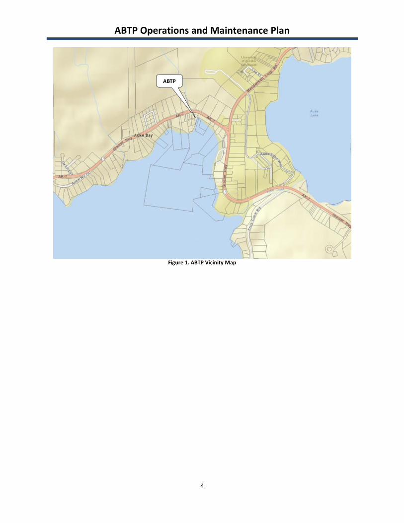
Included in this document are an overview of the facility, process components, best managementpractices, and general operational approach. A map of the facility and surrounding area is shown inFigure 1.
More detailed discussion of each process is provided in the Unit Process Control Procedures (UPCP)(Appendix B) and Standard Operating Procedures (SOPs) for each major process employed in the facility.Please refer to these documents for operational rationale, troubleshooting, and start up and shut downimpacts and procedures. SOPs are located in a separate binder and should be made available in thetreatment plant.
A sampling plan for the facility is included in this document. While there is some latitude on collectingand analyzing process samples, the permit samples noted in the plan must be collected on the time anddate specified, unless unusual circumstances prevent their collection at the appointed time. Moredetailed information regarding sampling procedures, data generation and acquisition and contractlaboratories is available in the Quality Assurance Project Plan (QAPP).
The overall objective of the facility is to operate as efficiently as possible while ensuring continuouscompliance in accordance with the APDES permit limits shown in the subsequent sections. In addition toyearly review, the OMP will be revised or amended whenever there is a change in the facility oroperation of the facility, which markedly increases the generation of pollutants, their release orpotential release to the waters of the United States through normal operations and ancillary activities.
ABTP Operations and Maintenance Plan
4
Figure 1. ABTP Vicinity Map
ABTP Operations and Maintenance Plan
5
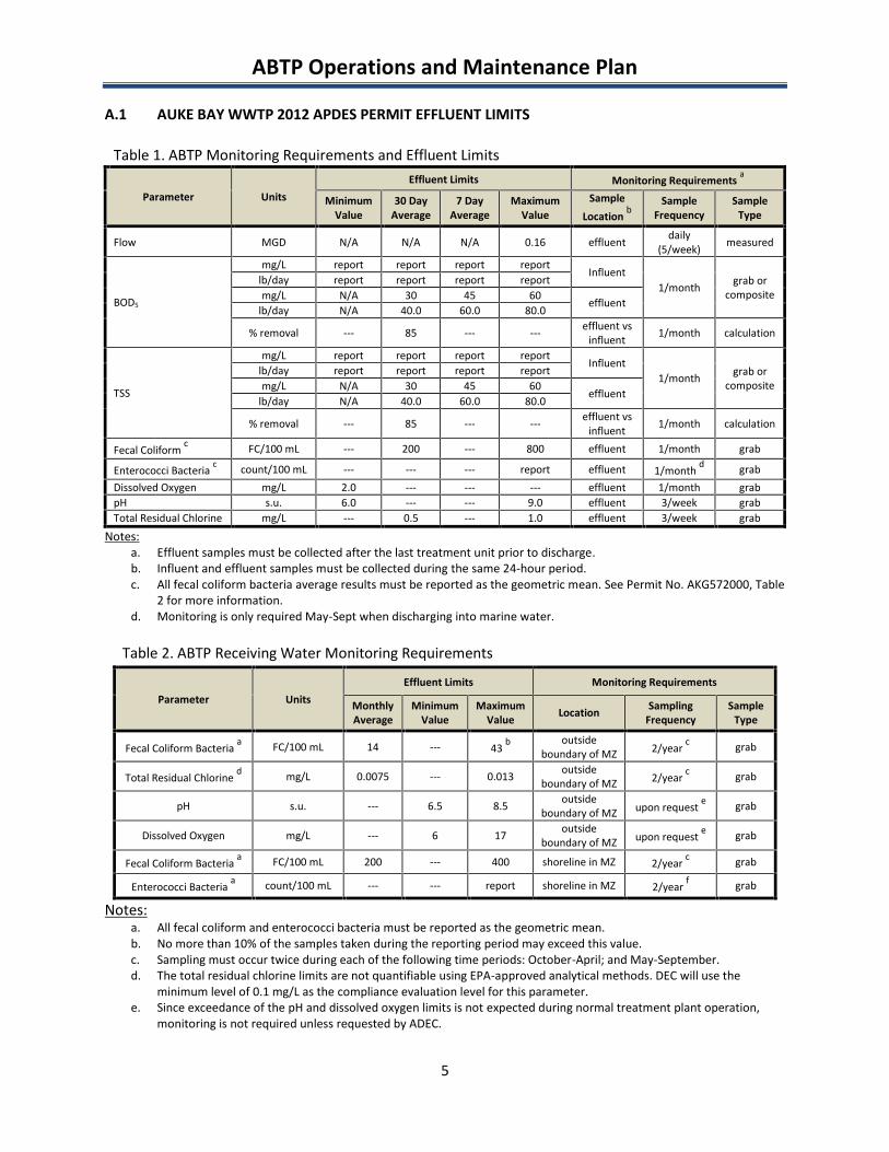
A.1 AUKE BAY WWTP 2012 APDES PERMIT EFFLUENT LIMITS
Table 1. ABTP Monitoring Requirements and Effluent Limits
Parameter UnitsEffluent Limits Monitoring Requirements a
MinimumValue
30 DayAverage
7 DayAverage
MaximumValue
SampleLocation b
SampleFrequency
SampleType
Flow MGD N/A N/A N/A 0.16 effluent daily(5/week) measured
BOD5
mg/L report report report reportInfluent
1/month grab orcomposite
lb/day report report report reportmg/L N/A 30 45 60
effluentlb/day N/A 40.0 60.0 80.0
% removal --- 85 --- --- effluent vsinfluent 1/month calculation
TSS
mg/L report report report reportInfluent
1/month grab orcomposite
lb/day report report report reportmg/L N/A 30 45 60
effluentlb/day N/A 40.0 60.0 80.0
% removal --- 85 --- --- effluent vsinfluent 1/month calculation
Fecal Coliform c FC/100 mL --- 200 --- 800 effluent 1/month grab
Enterococci Bacteria c count/100 mL --- --- --- report effluent 1/month d grabDissolved Oxygen mg/L 2.0 --- --- --- effluent 1/month grabpH s.u. 6.0 --- --- 9.0 effluent 3/week grabTotal Residual Chlorine mg/L --- 0.5 --- 1.0 effluent 3/week grab
Notes:a. Effluent samples must be collected after the last treatment unit prior to discharge.b. Influent and effluent samples must be collected during the same 24-hour period.c. All fecal coliform bacteria average results must be reported as the geometric mean. See Permit No. AKG572000, Table
2 for more information.d. Monitoring is only required May-Sept when discharging into marine water.
Table 2. ABTP Receiving Water Monitoring Requirements
Parameter UnitsEffluent Limits Monitoring Requirements
MonthlyAverage
MinimumValue
MaximumValue Location Sampling
FrequencySample
Type
Fecal Coliform Bacteria a FC/100 mL 14 --- 43 b outsideboundary of MZ 2/year c grab
Total Residual Chlorine d mg/L 0.0075 --- 0.013 outsideboundary of MZ 2/year c grab
pH s.u. --- 6.5 8.5 outsideboundary of MZ upon request e grab
Dissolved Oxygen mg/L --- 6 17 outsideboundary of MZ upon request e grab
Fecal Coliform Bacteria a FC/100 mL 200 --- 400 shoreline in MZ 2/year c grab
Enterococci Bacteria a count/100 mL --- --- report shoreline in MZ 2/year f grab
Notes:a. All fecal coliform and enterococci bacteria must be reported as the geometric mean.b. No more than 10% of the samples taken during the reporting period may exceed this value.c. Sampling must occur twice during each of the following time periods: October-April; and May-September.d. The total residual chlorine limits are not quantifiable using EPA-approved analytical methods. DEC will use the
minimum level of 0.1 mg/L as the compliance evaluation level for this parameter.e. Since exceedance of the pH and dissolved oxygen limits is not expected during normal treatment plant operation,
monitoring is not required unless requested by ADEC.
ABTP Operations and Maintenance Plan
6
f. Monitoring of enterococci bacteria is required twice during the time period of May through September. Samplingevents should take place during different months.
ABTP Operations and Maintenance Plan
7
B. FACILITY DESCRIPTION
The Auke Bay Wastewater Treatment Plant is a Level II, 0.16 MGD package plant. ABTP is an activatedsludge facility utilizing aeration and sludge digestion technologies. The facility is designed to treatdomestic wastewater from the CBJ community.
ABTP is open five days a week, Monday through Friday, and has at least one Level II licensed operator onstaff during business hours. During off hours and non-business days, an on-call operator makes dailyrounds and is the primary contact for emergencies. ABTP’s remote monitoring autodialer system alertsthe on-call operator of any issues occurring both during business hours and after hours.
The subsequent sections discuss the basic purpose of each process in the plant, what primary processunits or equipment are implement, and identify potential sources of pollution to the receiving waters.More detailed operating parameters are shown in the Process Control Strategy (Section C), UPCPs(Appendix B) and SOPs.
B.1 PLANT PROCESS
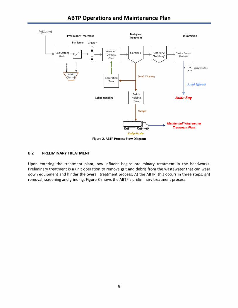
Figure 2 demonstrates the flow of wastewater and solids handling for ABTP. Wastewater enters thefacility through a 10-inch pipe with gate valve. Debris is removed in the headworks by grit channel, barscreen and grinder. Raw wastewater then enters a section of the basin referred to as the “contactzone,” where initial biological treatment occurs. The partially treated water flows to the two secondaryclarifiers for solids settling and “polishing”. Supernatant is gravity discharged over the weirs of theclarifiers and continues on to the chlorine contact chamber for disinfection by a sodium hypochloritesolution. The effluent is then dechlorinated as it flows through a sodium sulfite feeder system beforefinal discharge into Auke Bay. Solids from the secondary clarifiers are recirculated back through thereaeration basin or are wasted to an aerobic digester tank that is separate from the liquid treatmentprocess to be digested. Digested solids are transported by tanker truck to the Mendenhall WastewaterTreatment Plant for dewatering and final disposal.
The following sections will discuss the various stages and their purpose at ABTP: Preliminary Treatment- Grit removal, screening, grinding Secondary Treatment- Aeration basin, clarification Disinfection Side Streams Solids Handling-Secondary clarifier solids, waste removal, aerobic digestion, solids transport
ABTP Operations and Maintenance Plan
8
Influent
Grit SettlingBasin
AerationContact
Zone
Clarifier 1
Preliminary Treatment BiologicalTreatment
Grinder
SolidsDisposal
Bar Screen
Clarifier 2“Polishing”
Chorine ContactChamber
Auke Bay
Liquid Effluent
Sodium Sulfite
Disinfection
ReaerationTank
SolidsHolding
Tank
Solids Wasting
Sludge Hauler
Mendenhall WastewaterTreatment Plant
Solids Handling
Sludge
Figure 2. ABTP Process Flow Diagram
B.2 PRELIMINARY TREATMENT
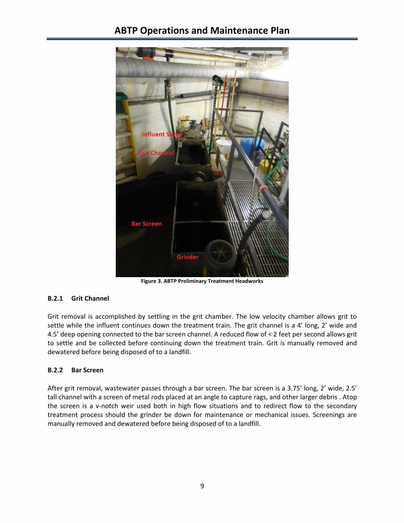
Upon entering the treatment plant, raw influent begins preliminary treatment in the headworks.Preliminary treatment is a unit operation to remove grit and debris from the wastewater that can weardown equipment and hinder the overall treatment process. At the ABTP, this occurs in three steps: gritremoval, screening and grinding. Figure 3 shows the ABTP’s preliminary treatment process.
ABTP Operations and Maintenance Plan
9
Figure 3. ABTP Preliminary Treatment Headworks
B.2.1 Grit Channel
Grit removal is accomplished by settling in the grit chamber. The low velocity chamber allows grit tosettle while the influent continues down the treatment train. The grit channel is a 4’ long, 2’ wide and4.5’ deep opening connected to the bar screen channel. A reduced flow of < 2 feet per second allows gritto settle and be collected before continuing down the treatment train. Grit is manually removed anddewatered before being disposed of to a landfill.
B.2.2 Bar Screen
After grit removal, wastewater passes through a bar screen. The bar screen is a 3.75’ long, 2’ wide, 2.5’tall channel with a screen of metal rods placed at an angle to capture rags, and other larger debris . Atopthe screen is a v-notch weir used both in high flow situations and to redirect flow to the secondarytreatment process should the grinder be down for maintenance or mechanical issues. Screenings aremanually removed and dewatered before being disposed of to a landfill.
ABTP Operations and Maintenance Plan
10
B.2.3 Grinder
The final stage of preliminary treatment is the Muffin Monster grinder. Larger particles not captured bythe grit channel and bar screen are reduced in size by the grinder to help prevent pipe and pump clogs.Influent continues from the grinder to the secondary treatment process.
B.3 SECONDARY TREATMENT
Following preliminary treatment is the secondary treatment process consisting of the contact aerationzone, reaeration system and clarification system.
Secondary, or biological treatment, is the portion of the process which removes dissolved and colloidalcompounds measured as biochemical oxygen demand (BOD), total suspended solids (TSS), ammonia andother compounds undesirable in the final effluent (see Table 1 for permit effluent limits). Microbesbreak down this organic waste using oxygen supplied by blowers. Following aeration, the partiallytreated water (now called mixed liquor) is allowed to settle in clarifiers to remove the larger flocculatedparticles that formed during the aeration process. The settled activated sludge particles are recycledback to the reaeration basin, to repopulate and reactivate the microorganisms prior to blending themwith the incoming raw wastewater in the contact aeration zone (see section B.8 for more information).
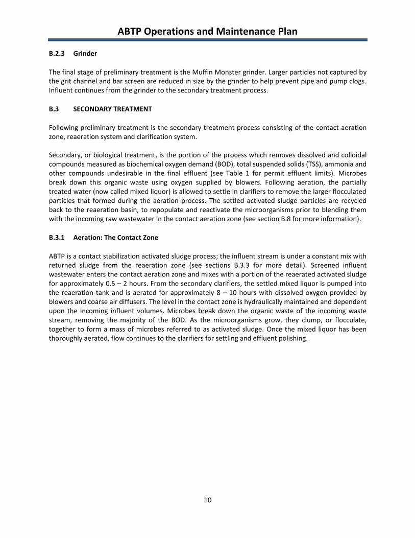
B.3.1 Aeration: The Contact Zone
ABTP is a contact stabilization activated sludge process; the influent stream is under a constant mix withreturned sludge from the reaeration zone (see sections B.3.3 for more detail). Screened influentwastewater enters the contact aeration zone and mixes with a portion of the reaerated activated sludgefor approximately 0.5 – 2 hours. From the secondary clarifiers, the settled mixed liquor is pumped intothe reaeration tank and is aerated for approximately 8 – 10 hours with dissolved oxygen provided byblowers and coarse air diffusers. The level in the contact zone is hydraulically maintained and dependentupon the incoming influent volumes. Microbes break down the organic waste of the incoming wastestream, removing the majority of the BOD. As the microorganisms grow, they clump, or flocculate,together to form a mass of microbes referred to as activated sludge. Once the mixed liquor has beenthoroughly aerated, flow continues to the clarifiers for settling and effluent polishing.
ABTP Operations and Maintenance Plan
11
Figure 4. ABTP Contact Aeration Zone
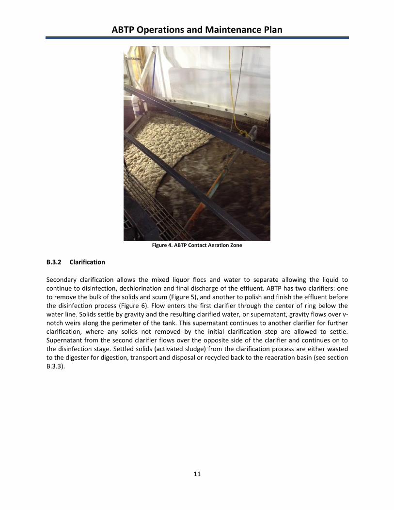
B.3.2 Clarification
Secondary clarification allows the mixed liquor flocs and water to separate allowing the liquid tocontinue to disinfection, dechlorination and final discharge of the effluent. ABTP has two clarifiers: oneto remove the bulk of the solids and scum (Figure 5), and another to polish and finish the effluent beforethe disinfection process (Figure 6). Flow enters the first clarifier through the center of ring below thewater line. Solids settle by gravity and the resulting clarified water, or supernatant, gravity flows over v-notch weirs along the perimeter of the tank. This supernatant continues to another clarifier for furtherclarification, where any solids not removed by the initial clarification step are allowed to settle.Supernatant from the second clarifier flows over the opposite side of the clarifier and continues on tothe disinfection stage. Settled solids (activated sludge) from the clarification process are either wastedto the digester for digestion, transport and disposal or recycled back to the reaeration basin (see sectionB.3.3).
ABTP Operations and Maintenance Plan
12
Figure 5. ABTP Secondary Clarifier
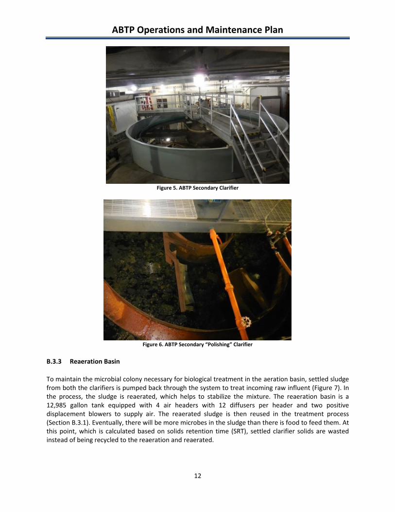
Figure 6. ABTP Secondary “Polishing” Clarifier
B.3.3 Reaeration Basin
To maintain the microbial colony necessary for biological treatment in the aeration basin, settled sludgefrom both the clarifiers is pumped back through the system to treat incoming raw influent (Figure 7). Inthe process, the sludge is reaerated, which helps to stabilize the mixture. The reaeration basin is a12,985 gallon tank equipped with 4 air headers with 12 diffusers per header and two positivedisplacement blowers to supply air. The reaerated sludge is then reused in the treatment process(Section B.3.1). Eventually, there will be more microbes in the sludge than there is food to feed them. Atthis point, which is calculated based on solids retention time (SRT), settled clarifier solids are wastedinstead of being recycled to the reaeration and reaerated.
ABTP Operations and Maintenance Plan
13
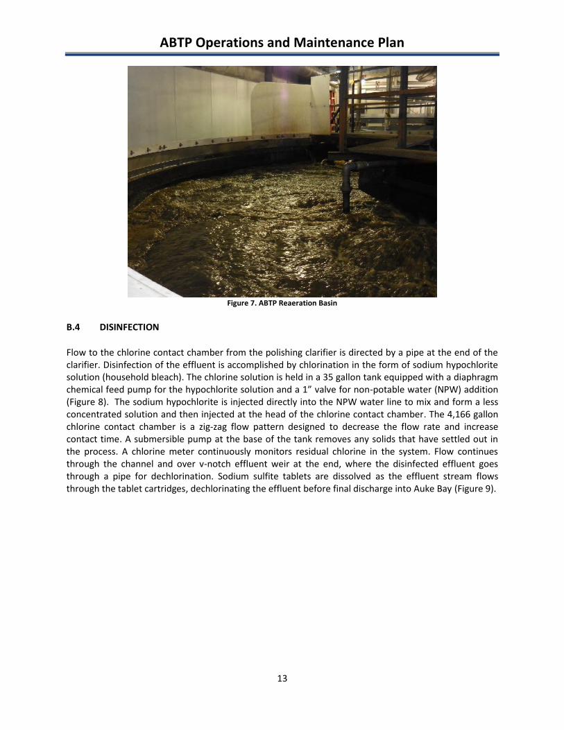
Figure 7. ABTP Reaeration Basin
B.4 DISINFECTION
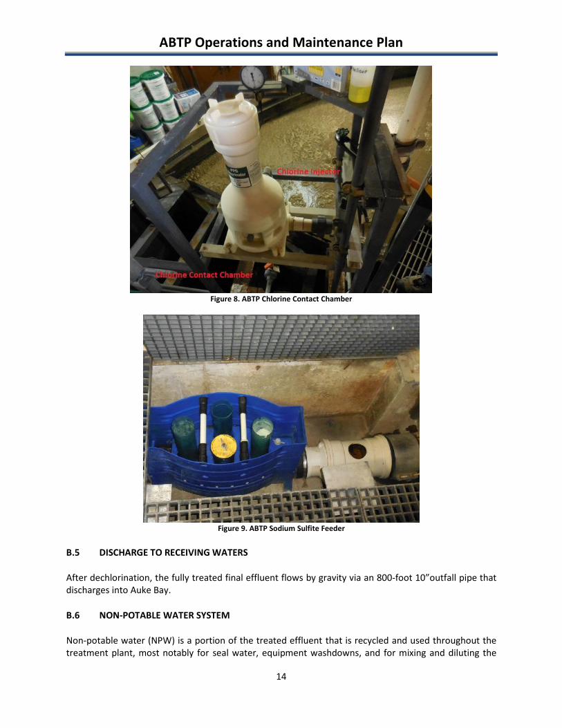
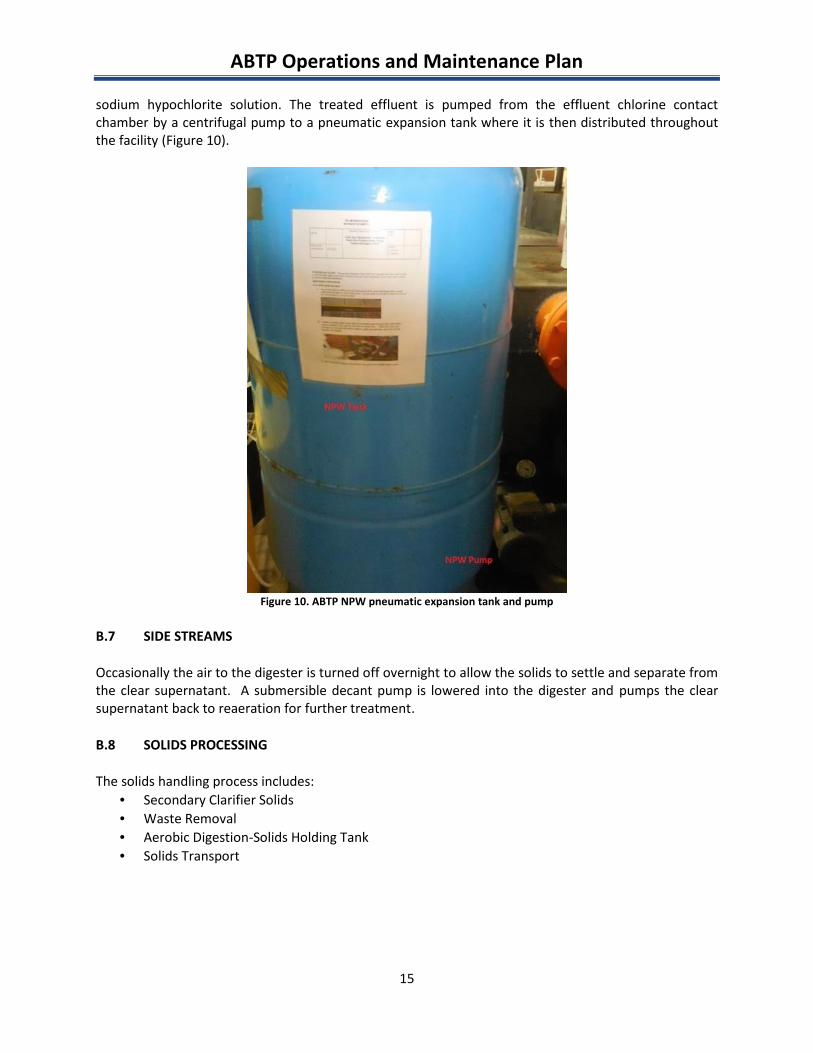
Flow to the chlorine contact chamber from the polishing clarifier is directed by a pipe at the end of theclarifier. Disinfection of the effluent is accomplished by chlorination in the form of sodium hypochloritesolution (household bleach). The chlorine solution is held in a 35 gallon tank equipped with a diaphragmchemical feed pump for the hypochlorite solution and a 1” valve for non-potable water (NPW) addition(Figure 8). The sodium hypochlorite is injected directly into the NPW water line to mix and form a lessconcentrated solution and then injected at the head of the chlorine contact chamber. The 4,166 gallonchlorine contact chamber is a zig-zag flow pattern designed to decrease the flow rate and increasecontact time. A submersible pump at the base of the tank removes any solids that have settled out inthe process. A chlorine meter continuously monitors residual chlorine in the system. Flow continuesthrough the channel and over v-notch effluent weir at the end, where the disinfected effluent goesthrough a pipe for dechlorination. Sodium sulfite tablets are dissolved as the effluent stream flowsthrough the tablet cartridges, dechlorinating the effluent before final discharge into Auke Bay (Figure 9).
ABTP Operations and Maintenance Plan
14
Figure 8. ABTP Chlorine Contact Chamber
Figure 9. ABTP Sodium Sulfite Feeder
B.5 DISCHARGE TO RECEIVING WATERS
After dechlorination, the fully treated final effluent flows by gravity via an 800-foot 10”outfall pipe thatdischarges into Auke Bay.
B.6 NON-POTABLE WATER SYSTEM
Non-potable water (NPW) is a portion of the treated effluent that is recycled and used throughout thetreatment plant, most notably for seal water, equipment washdowns, and for mixing and diluting the
ABTP Operations and Maintenance Plan
15
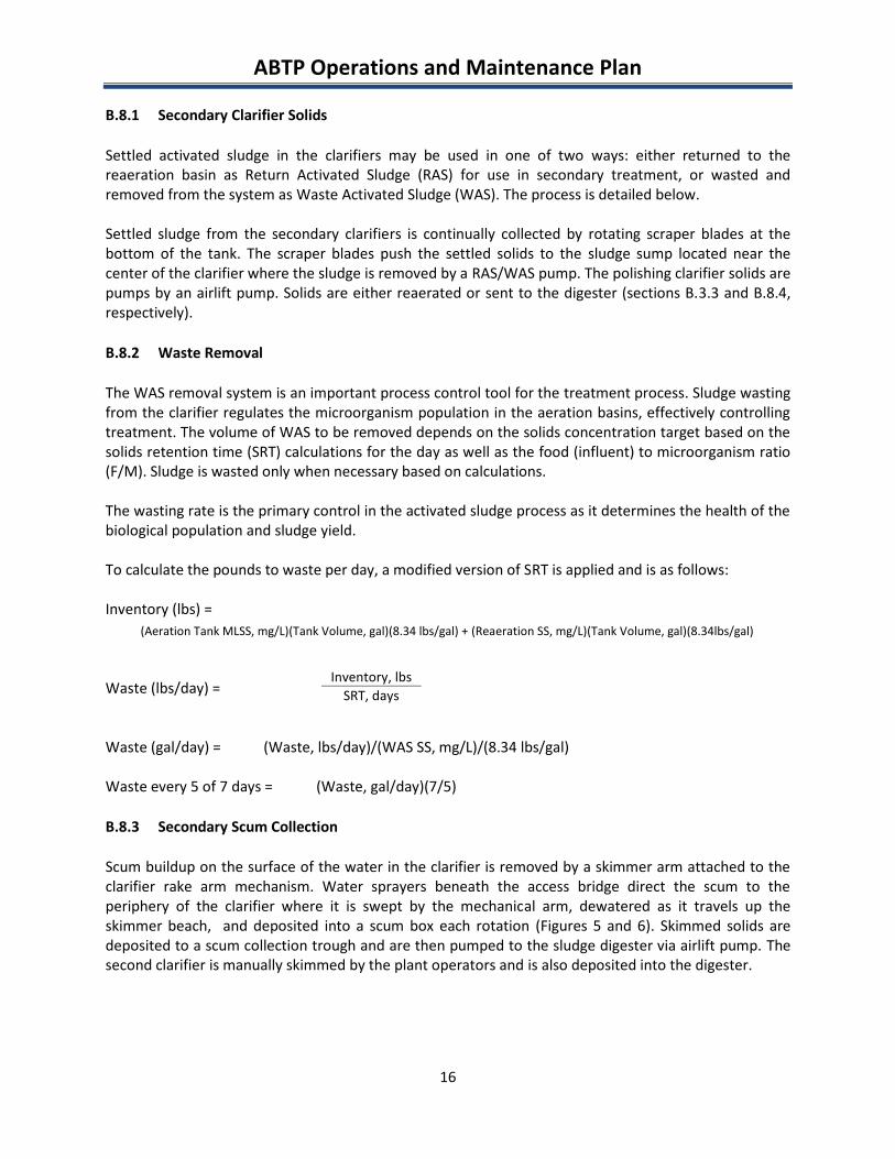
sodium hypochlorite solution. The treated effluent is pumped from the effluent chlorine contactchamber by a centrifugal pump to a pneumatic expansion tank where it is then distributed throughoutthe facility (Figure 10).
Figure 10. ABTP NPW pneumatic expansion tank and pump
B.7 SIDE STREAMS
Occasionally the air to the digester is turned off overnight to allow the solids to settle and separate fromthe clear supernatant. A submersible decant pump is lowered into the digester and pumps the clearsupernatant back to reaeration for further treatment.
B.8 SOLIDS PROCESSING
The solids handling process includes: Secondary Clarifier Solids Waste Removal Aerobic Digestion-Solids Holding Tank Solids Transport
ABTP Operations and Maintenance Plan
16
B.8.1 Secondary Clarifier Solids
Settled activated sludge in the clarifiers may be used in one of two ways: either returned to thereaeration basin as Return Activated Sludge (RAS) for use in secondary treatment, or wasted andremoved from the system as Waste Activated Sludge (WAS). The process is detailed below.
Settled sludge from the secondary clarifiers is continually collected by rotating scraper blades at thebottom of the tank. The scraper blades push the settled solids to the sludge sump located near thecenter of the clarifier where the sludge is removed by a RAS/WAS pump. The polishing clarifier solids arepumps by an airlift pump. Solids are either reaerated or sent to the digester (sections B.3.3 and B.8.4,respectively).
B.8.2 Waste Removal
The WAS removal system is an important process control tool for the treatment process. Sludge wastingfrom the clarifier regulates the microorganism population in the aeration basins, effectively controllingtreatment. The volume of WAS to be removed depends on the solids concentration target based on thesolids retention time (SRT) calculations for the day as well as the food (influent) to microorganism ratio(F/M). Sludge is wasted only when necessary based on calculations.
The wasting rate is the primary control in the activated sludge process as it determines the health of thebiological population and sludge yield.
To calculate the pounds to waste per day, a modified version of SRT is applied and is as follows:
Inventory (lbs) =
Waste (lbs/day) =
Waste (gal/day) = (Waste, lbs/day)/(WAS SS, mg/L)/(8.34 lbs/gal)
Waste every 5 of 7 days = (Waste, gal/day)(7/5)
B.8.3 Secondary Scum Collection
Scum buildup on the surface of the water in the clarifier is removed by a skimmer arm attached to theclarifier rake arm mechanism. Water sprayers beneath the access bridge direct the scum to theperiphery of the clarifier where it is swept by the mechanical arm, dewatered as it travels up theskimmer beach, and deposited into a scum box each rotation (Figures 5 and 6). Skimmed solids aredeposited to a scum collection trough and are then pumped to the sludge digester via airlift pump. Thesecond clarifier is manually skimmed by the plant operators and is also deposited into the digester.
(Aeration Tank MLSS, mg/L)(Tank Volume, gal)(8.34 lbs/gal) + (Reaeration SS, mg/L)(Tank Volume, gal)(8.34lbs/gal)
Inventory, lbsSRT, days
ABTP Operations and Maintenance Plan
17
B.8.4 Aerobic Digestion and Solids Transport
Most often, solids will be recirculated through the plant via the reaeration basin (section B.3.3).However, once the microbial population is greater than the volume of influent to feed them, theactivated sludge is wasted to the solids holding tank. Wasting rates are based on the solids retentiontime (SRT) and generally occurs once daily in small volumes.
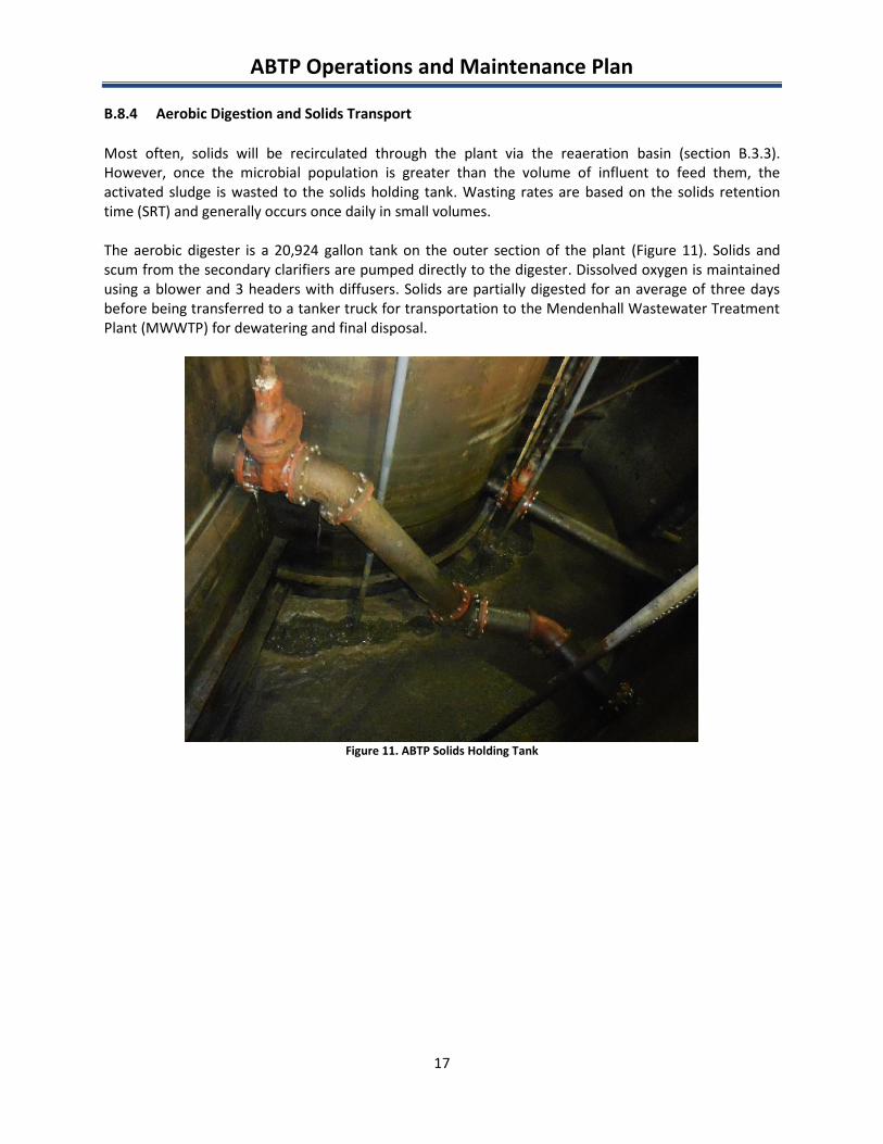
The aerobic digester is a 20,924 gallon tank on the outer section of the plant (Figure 11). Solids andscum from the secondary clarifiers are pumped directly to the digester. Dissolved oxygen is maintainedusing a blower and 3 headers with diffusers. Solids are partially digested for an average of three daysbefore being transferred to a tanker truck for transportation to the Mendenhall Wastewater TreatmentPlant (MWWTP) for dewatering and final disposal.
Figure 11. ABTP Solids Holding Tank
ABTP Operations and Maintenance Plan
18
C. ALARM DIALING
The ABTP is equipped with an auto-dialer system to notify on-call staff of alarm conditions while theplant is unmanned via a telephony system. The auto-dialer system monitors several pieces of criticalequipment and will dial the on-call operator if alarm conditions exist. The specific conditions andequipment alarms are listed below:
Blower No.1 Failure Blower No.2 Failure Clarifier No.1 Drive Failure Clarifier No.2 Drive Failure Grinder Failure Power Failure
The autodialer is also designed to recharge its own dedicated battery back-up power supply.
The facility is also monitored 24/7 for smoke and fire using a Honeywell Silent Knight System and anIntelliknight Fire Alarm Control Communicator model 5700. If smoke or fire is detected thecommunicator will send an alarm to LJ-Alarm Monitoring Services and they will respond by contactingthe fire department as well as the on-call operator for the facility.
ABTP Operations and Maintenance Plan
19
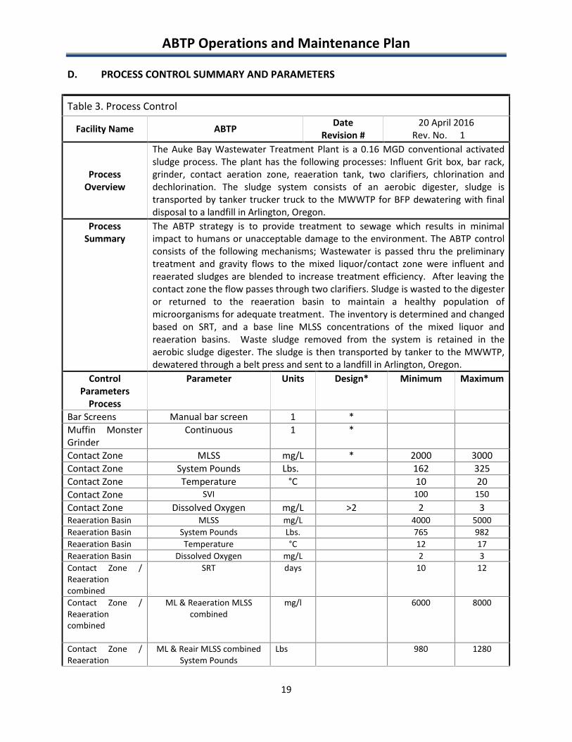
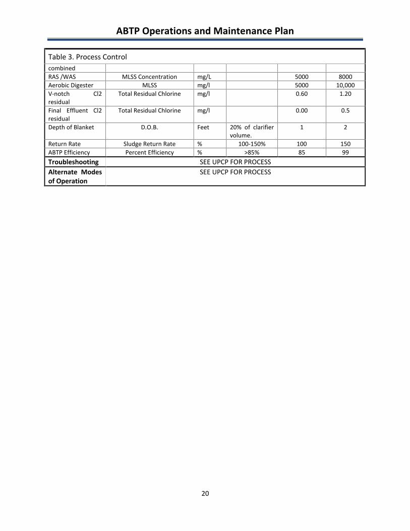
D. PROCESS CONTROL SUMMARY AND PARAMETERS
Table 3. Process Control
Facility Name ABTP DateRevision #
20 April 2016Rev. No. 1
ProcessOverview
The Auke Bay Wastewater Treatment Plant is a 0.16 MGD conventional activatedsludge process. The plant has the following processes: Influent Grit box, bar rack,grinder, contact aeration zone, reaeration tank, two clarifiers, chlorination anddechlorination. The sludge system consists of an aerobic digester, sludge istransported by tanker trucker truck to the MWWTP for BFP dewatering with finaldisposal to a landfill in Arlington, Oregon.
ProcessSummary
The ABTP strategy is to provide treatment to sewage which results in minimalimpact to humans or unacceptable damage to the environment. The ABTP controlconsists of the following mechanisms; Wastewater is passed thru the preliminarytreatment and gravity flows to the mixed liquor/contact zone were influent andreaerated sludges are blended to increase treatment efficiency. After leaving thecontact zone the flow passes through two clarifiers. Sludge is wasted to the digesteror returned to the reaeration basin to maintain a healthy population ofmicroorganisms for adequate treatment. The inventory is determined and changedbased on SRT, and a base line MLSS concentrations of the mixed liquor andreaeration basins. Waste sludge removed from the system is retained in theaerobic sludge digester. The sludge is then transported by tanker to the MWWTP,dewatered through a belt press and sent to a landfill in Arlington, Oregon.
ControlParameters
Process
Parameter Units Design* Minimum Maximum
Bar Screens Manual bar screen 1 *Muffin MonsterGrinder
Continuous 1 *
Contact Zone MLSS mg/L * 2000 3000Contact Zone System Pounds Lbs. 162 325Contact Zone Temperature °C 10 20Contact Zone SVI 100 150Contact Zone Dissolved Oxygen mg/L >2 2 3Reaeration Basin MLSS mg/L 4000 5000Reaeration Basin System Pounds Lbs. 765 982Reaeration Basin Temperature °C 12 17Reaeration Basin Dissolved Oxygen mg/L 2 3Contact Zone /Reaerationcombined
SRT days 10 12
Contact Zone /Reaerationcombined
ML & Reaeration MLSScombined
mg/l 6000 8000
Contact Zone /Reaeration
ML & Reair MLSS combinedSystem Pounds
Lbs 980 1280
ABTP Operations and Maintenance Plan
20
Table 3. Process ControlcombinedRAS /WAS MLSS Concentration mg/L 5000 8000Aerobic Digester MLSS mg/l 5000 10,000V-notch Cl2residual
Total Residual Chlorine mg/l 0.60 1.20
Final Effluent Cl2residual
Total Residual Chlorine mg/l 0.00 0.5
Depth of Blanket D.O.B. Feet 20% of clarifiervolume.
1 2
Return Rate Sludge Return Rate % 100-150% 100 150ABTP Efficiency Percent Efficiency % >85% 85 99Troubleshooting SEE UPCP FOR PROCESSAlternate Modesof Operation
SEE UPCP FOR PROCESS
ABTP Operations and Maintenance Plan
21
E. SAMPLING PLAN
This section is supplemental to the CBJ Quality Assurance Project Plan (QAPP) and does not replace orshould not be mistaken for the actual QAPP in use for the CBJ.
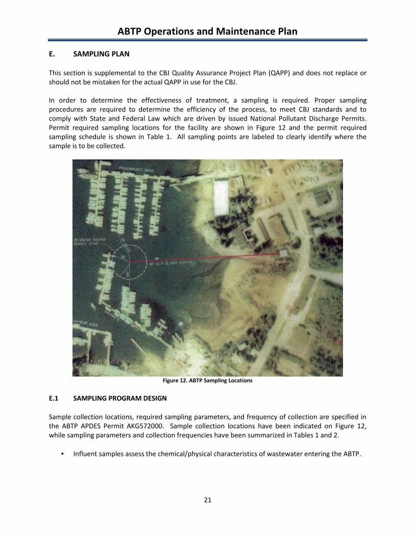
In order to determine the effectiveness of treatment, a sampling is required. Proper samplingprocedures are required to determine the efficiency of the process, to meet CBJ standards and tocomply with State and Federal Law which are driven by issued National Pollutant Discharge Permits.Permit required sampling locations for the facility are shown in Figure 12 and the permit requiredsampling schedule is shown in Table 1. All sampling points are labeled to clearly identify where thesample is to be collected.
Figure 12. ABTP Sampling Locations
E.1 SAMPLING PROGRAM DESIGN
Sample collection locations, required sampling parameters, and frequency of collection are specified inthe ABTP APDES Permit AKG572000. Sample collection locations have been indicated on Figure 12,while sampling parameters and collection frequencies have been summarized in Tables 1 and 2.
Influent samples assess the chemical/physical characteristics of wastewater entering the ABTP.
ABTP Operations and Maintenance Plan
22
Effluent samples assess the chemical/physical characteristics of the treated wastewaterdischarged from the plant and are used to calculate the percent removal for BOD and TSS whencompared to the influent sewage.
Receiving water samples are collected within and outside of the mixing zone to assess anypotential water quality impacts generated by discharge of the treated effluent to the receivingwater body. The ABTP treated effluent is discharged to Statter Harbor located in Auke Baythrough an 800 foot long outfall pipe.
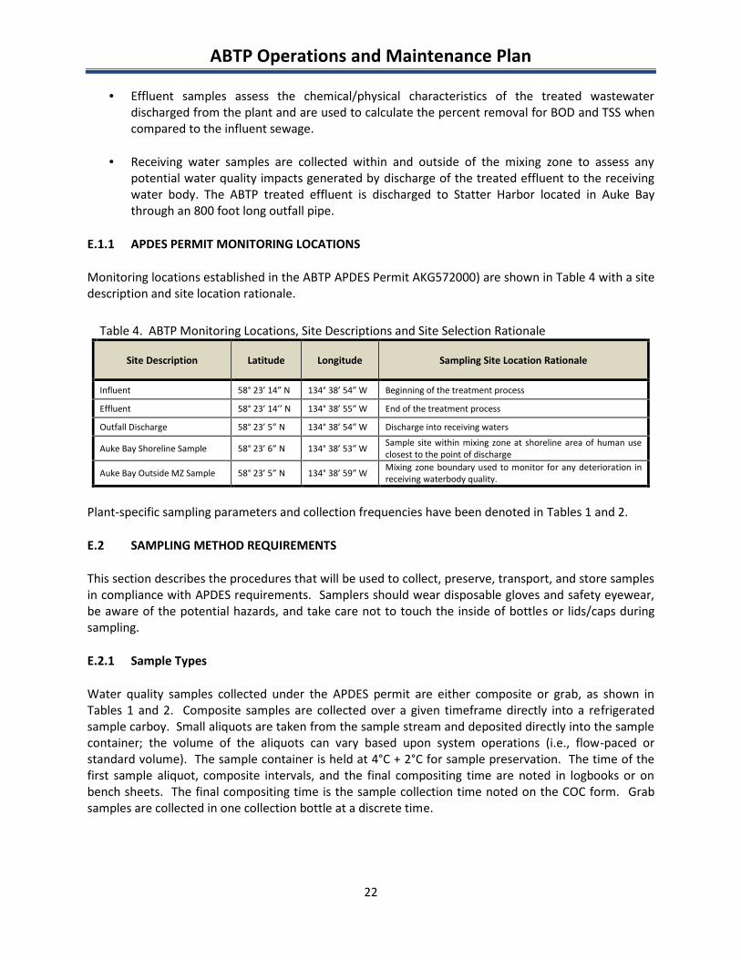
E.1.1 APDES PERMIT MONITORING LOCATIONS
Monitoring locations established in the ABTP APDES Permit AKG572000) are shown in Table 4 with a sitedescription and site location rationale.
Table 4. ABTP Monitoring Locations, Site Descriptions and Site Selection Rationale
Site Description Latitude Longitude Sampling Site Location Rationale
Influent 58° 23’ 14” N 134° 38’ 54” W Beginning of the treatment process
Effluent 58° 23’ 14’’ N 134° 38’ 55” W End of the treatment process
Outfall Discharge 58° 23’ 5” N 134° 38’ 54” W Discharge into receiving waters
Auke Bay Shoreline Sample 58° 23’ 6” N 134° 38’ 53” W Sample site within mixing zone at shoreline area of human useclosest to the point of discharge
Auke Bay Outside MZ Sample 58° 23’ 5” N 134° 38’ 59” W Mixing zone boundary used to monitor for any deterioration inreceiving waterbody quality.
Plant-specific sampling parameters and collection frequencies have been denoted in Tables 1 and 2.
E.2 SAMPLING METHOD REQUIREMENTS
This section describes the procedures that will be used to collect, preserve, transport, and store samplesin compliance with APDES requirements. Samplers should wear disposable gloves and safety eyewear,be aware of the potential hazards, and take care not to touch the inside of bottles or lids/caps duringsampling.
E.2.1 Sample Types
Water quality samples collected under the APDES permit are either composite or grab, as shown inTables 1 and 2. Composite samples are collected over a given timeframe directly into a refrigeratedsample carboy. Small aliquots are taken from the sample stream and deposited directly into the samplecontainer; the volume of the aliquots can vary based upon system operations (i.e., flow-paced orstandard volume). The sample container is held at 4°C + 2°C for sample preservation. The time of thefirst sample aliquot, composite intervals, and the final compositing time are noted in logbooks or onbench sheets. The final compositing time is the sample collection time noted on the COC form. Grabsamples are collected in one collection bottle at a discrete time.
ABTP Operations and Maintenance Plan
23
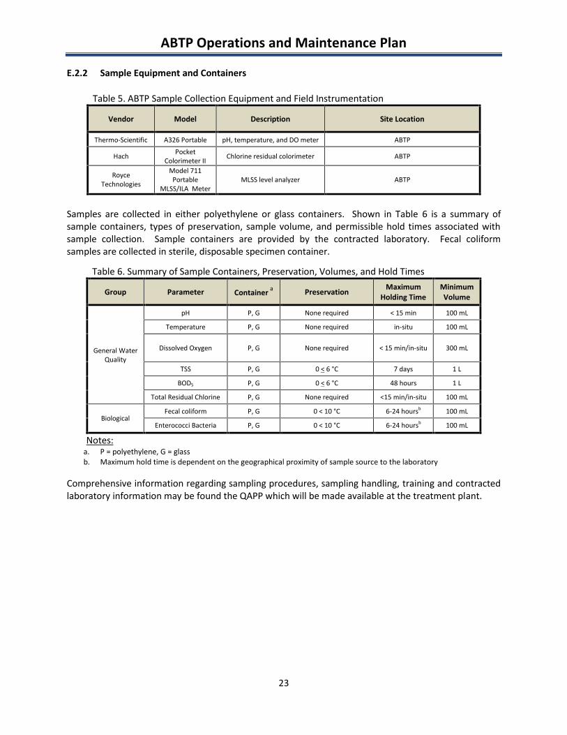
E.2.2 Sample Equipment and Containers
Table 5. ABTP Sample Collection Equipment and Field Instrumentation
Vendor Model Description Site Location
Thermo-Scientific A326 Portable pH, temperature, and DO meter ABTP
Hach PocketColorimeter II Chlorine residual colorimeter ABTP
RoyceTechnologies
Model 711Portable
MLSS/ILA MeterMLSS level analyzer ABTP
Samples are collected in either polyethylene or glass containers. Shown in Table 6 is a summary ofsample containers, types of preservation, sample volume, and permissible hold times associated withsample collection. Sample containers are provided by the contracted laboratory. Fecal coliformsamples are collected in sterile, disposable specimen container.
Table 6. Summary of Sample Containers, Preservation, Volumes, and Hold Times
Group Parameter Container a Preservation MaximumHolding Time
MinimumVolume
General WaterQuality
pH P, G None required < 15 min 100 mL
Temperature P, G None required in-situ 100 mL
Dissolved Oxygen P, G None required < 15 min/in-situ 300 mL
TSS P, G 0 < 6 °C 7 days 1 L
BOD5 P, G 0 < 6 °C 48 hours 1 L
Total Residual Chlorine P, G None required <15 min/in-situ 100 mL
BiologicalFecal coliform P, G 0 < 10 °C 6-24 hoursb 100 mL
Enterococci Bacteria P, G 0 < 10 °C 6-24 hoursb 100 mL
Notes:a. P = polyethylene, G = glassb. Maximum hold time is dependent on the geographical proximity of sample source to the laboratory
Comprehensive information regarding sampling procedures, sampling handling, training and contractedlaboratory information may be found the QAPP which will be made available at the treatment plant.
ABTP Operations and Maintenance Plan
24
F. POLLUTION PREVENTION AND CONTROL
While not a requirement of the ABTP APDES permit, included in this section are best managementpractices (BMPs) that demonstrate measures to prevent or minimize the potential for the release ofpollutants into Auke Bay. This section discusses the pollution prevention and control measures in placefor both principal and ancillary operations
F.1 SPILL PREVENTION AND CONTROL
Potential pollutants to Auke Bay are identified as: activated sludge and chemicals used in ancillaryoperations such as lubricants, fuel, paints and cleaning products. Laboratory and process control work isminimal and does not require any hazardous materials. Storage and handling of these pollutants areoutlined in the sections below.
F.1.1 Sludge Storage and Transport
Sludge is pumped directly from the aerobic digester to a tanker truck. Within the treatment plant, drainsand sumps are located throughout to send any spilled or leaked sludge back to the headworks.Depending on the nature of any spills on the facility grounds, they are contained and cleanedimmediately and potentially reported to ADEC.
F.1.2 Ancillary Operations
Inventories of lubricants, fuels, paint and cleaning products are maintained at low inventories, andsegregated and stored in OSHA approved building areas or cabinets. Storage locations and areas aredesigned and situated for easy control of drainage and/or cleanup, and to prevent an accidental spillageof materials from entering the process waste stream. Small spills of these materials are immediatelycleaned by the Operators.
Refuse waste is collected by a contracting company for transportation to the local landfill. Operatorscollect and transport all recyclables to the local recycling center and used oil is collected and recycled.
F.2 PREVENTIVE MAINTENANCE PROGRAM
The ABTP uses Antero, a computerized maintenance management program. The Operator andMaintenance staff uses the program to set up recurring preventative maintenance schedules for thefacility assets based on the equipment manufacturer’s recommendations. The program is also used totrack corrective maintenance repairs performed on the facility assets.
F.3 MINIMIZATION OF INDUSTRIAL POLLUTANT INPUTS
Inputs from industrial users are monitored by industrial user surveys and source control sampling.
An industrial user survey is performed once per permit cycle. Commercial and industrial facilities whichmay be discharging non-domestic wastewater or other chemicals and materials into the sewer systemare identified. In addition, the volume of waste input to the sewer system from these sources is
ABTP Operations and Maintenance Plan
25
identified. This information assists ABTP in identifying any new significant industrial users, and theamount and type of waste being discharged to the municipal sewer system.
A source control program was developed to monitor various locations around the sewer system forindustrial inputs. An ISCO composite sampler is placed in a predetermined manhole and allowed tosample for four days. Samples are then taken to a contracted laboratory and are analyzed for BOD, COD,TSS, ammonia, phosphorus, fats, oils and grease (FOG) and total Kjeldahl nitrogen. Sampling locationsare rotated bi-weekly to obtain a comprehensive analysis of industrial inputs.
F.4 PUBLIC EDUCATION AND OUTREACH
A public information and education program, an element of the BMPs, has been implemented for alltreatment plants in the CBJ Wastewater Division. The complete details of this program are outlined in inthe Public Information and Education Program Plan. A short summary of some activities follows:
CBJ Divisions of Wastewater and Hazardous Waste (HW) have partnered to provide properdisposal guidelines for household hazardous waste. Wastewater developed a flyer outliningproper disposal of hazardous waste, specifically stating products such as paints, pesticides,spent fuel and motor oil, etc. should not be disposed of in the sewer. The flyer is distributed tothe public on a regular basis and lists contact information of Wastewater and HW to provideguidance over the telephone.
All facilities are open to the public for tours, though most tours are scheduled at the MendenhallWastewater Treatment Plant. Tours focus on basic wastewater treatment processes but alsoprovide information about proper disposal of household hazardous waste. Educationalpamphlets regarding proper disposal of pollutants are available to the public at the treatmentplant.
A reuse program, the HazBin Exchange Program, sponsored by the CBJ’s Waste ManagementDivision has had notable success. If a material is over 50% full and in its original packaging, otherresidents are allowed to obtain the material for free. A waiver is required for liability purposesas to the material’s integrity. Currently, citizens are taking 2000 lbs. per month of partially usedproducts that would otherwise be disposed of as hazardous waste.
CBJ Wastewater has ongoing construction projects to replace and repair sewer systemcomponents to reduce infiltration/inflow into the sewer system.
F.5 WATER CONSERVATION
The Auke Bay Wastewater Treatment Plant has two water systems, potable and non-potablerecirculated effluent.
The potable water is treated drinking water from the CBJ Water Utility system and is used for alldomestic needs throughout the facility. NPW is a portion of the treated effluent that is recycledthroughout the treatment plant, most notably for seal water and diluting the sodium hypochloritesolution. The treated effluent is pumped from the effluent chlorine contact chamber by a centrifugalpump and is transferred to a pneumatic expansion tank where it is distributed throughout the facility.
ABTP Operations and Maintenance Plan
Appendix AAPDES Permit & Fact Sheet
Page 1 of 4
AKG572004
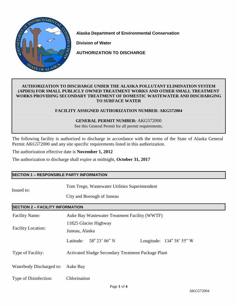
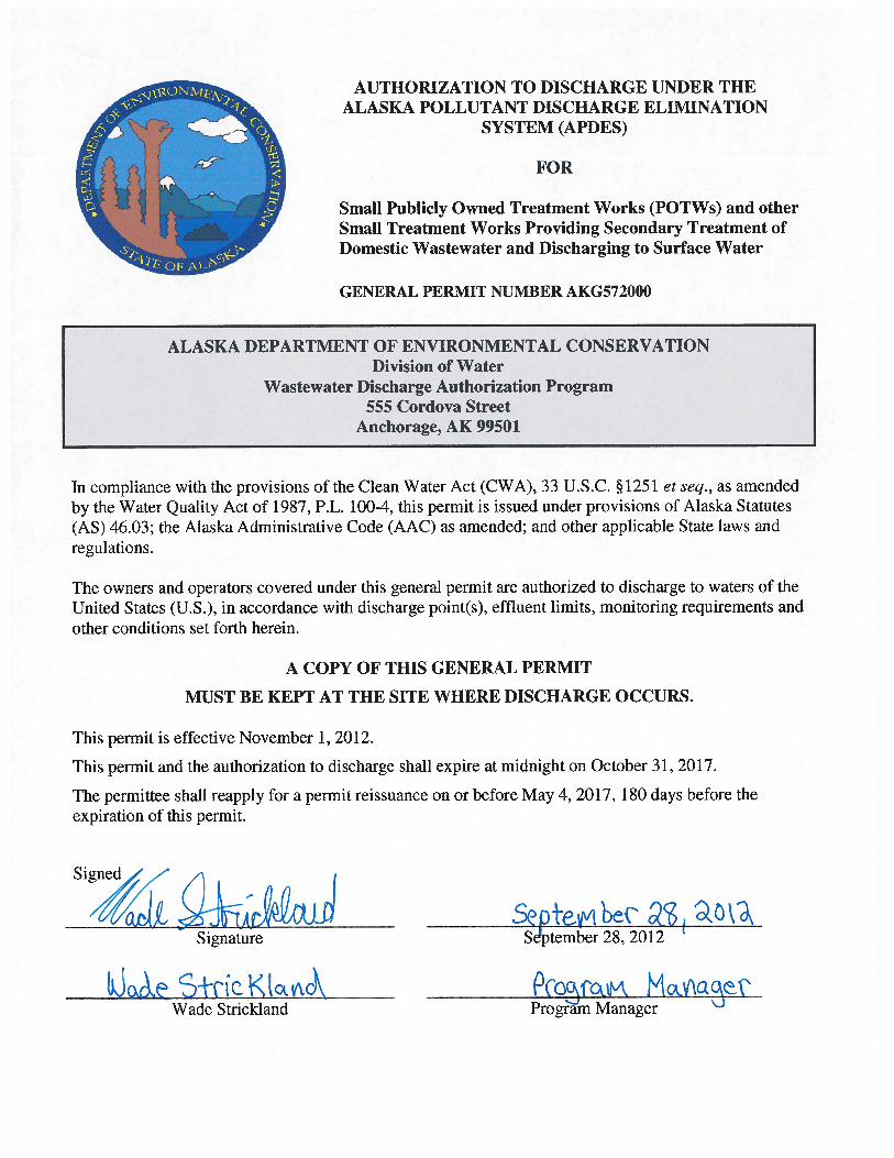
Alaska Department of Environmental Conservation Division of Water AUTHORIZATION TO DISCHARGE
AUTHORIZATION TO DISCHARGE UNDER THE ALASKA POLLUTANT ELIMINATION SYSTEM
(APDES) FOR SMALL PUBLICLY OWNED TREATMENT WORKS AND OTHER SMALL TREATMENT
WORKS PROVIDING SECONDARY TREATMENT OF DOMESTIC WASTEWATER AND DISCHARGING
TO SURFACE WATER
FACILITY ASSIGNED AUTHORIZATION NUMBER: AKG572004
GENERAL PERMIT NUMBER: AKG572000
See this General Permit for all permit requirements.
The following facility is authorized to discharge in accordance with the terms of the State of Alaska General
Permit AKG572000 and any site specific requirements listed in this authorization.
The authorization effective date is November 1, 2012
The authorization to discharge shall expire at midnight, October 31, 2017
SECTION 1 – RESPONSIBLE PARTY INFORMATION
Issued to: Tom Trego, Wastewater Utilities Superintendent
City and Borough of Juneau
SECTION 2 – FACILITY INFORMATION
Facility Name: Auke Bay Wastewater Treatment Facility (WWTF)
Facility Location: 11825 Glacier Highway
Juneau, Alaska
Latitude: 58o 23’ 06” N Longitude: 134
o 38’ 55” W
Type of Facility: Activated Sludge Secondary Treatment Package Plant
Waterbody Discharged to: Auke Bay
Type of Disinfection: Chlorination
Page 2 of 4
AKG572004
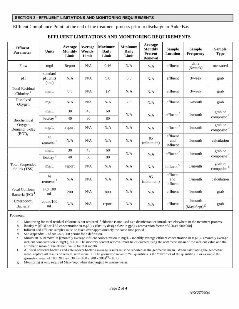
SECTION 3 –EFFLUENT LIMITATIONS AND MONITORING REQUIREMENTS
Effluent Compliance Point: at the end of the treatment process prior to discharge to Auke Bay
EFFLUENT LIMITATIONS AND MONITORING REQUIREMENTS
Effluent
Parameter Units
Average
Monthly
Limit
Average
Weekly
Limit
Maximum
Daily
Limit
Minimum
Daily
Limit
Average
Monthly
Percent
Removal
Sample
Location
Sample
Frequency
Sample
Type
Flow mgd Report N/A 0.16 N/A N/A effluent daily
(5/week) measured
pH
standard
pH units
(s.u.)
N/A N/A 9.0 6.0 N/A effluent 3/week grab
Total Residual
Chlorine a
mg/L 0.5 N/A 1.0 N/A N/A effluent 3/week grab
Dissolved
Oxygen mg/L N/A N/A N/A 2.0 N/A effluent 1/month grab
Biochemical
Oxygen
Demand, 5-day
(BOD5)
mg/L 30 45 60 N/A N/A effluent
c 1/month
grab or
composite d
lbs/day b 40 60 80
mg/L report N/A N/A N/A N/A influent c 1/month
grab or
composite d
%
removal e
N/A N/A N/A N/A 85
(minimum)
effluent
and
influent
1/month calculation
Total Suspended
Solids (TSS)
mg/L 30 45 60 N/A N/A effluent
c 1/month
grab or
composite d
lbs/day b
40 60 80
mg/L report N/A N/A N/A N/A influent c 1/month
grab or
composite d
%
removal e
N/A N/A N/A N/A 85
(minimum)
effluent
and
influent
1/month calculation
Fecal Coliform
Bacteria (FC) f
FC/ 100
mL 200 N/A 800 N/A N/A effluent 1/month grab
Enterococci
Bacteriaf
count/100
mL N/A N/A report N/A N/A effluent
1/month
(May-Sept) g
grab
Footnotes:
a. Monitoring for total residual chlorine is not required if chlorine is not used as a disinfectant or introduced elsewhere in the treatment process.
b. lbs/day = [(BOD or TSS concentration in mg/L) x (facility design flow in gpd) x (conversion factor of 8.34)/1,000,000]
c. Influent and effluent samples must be taken over approximately the same time period.
d. See Appendix C of AKG572000 permit for a definition.
e. Minimum % Removal = [(monthly average influent concentration in mg/L - monthly average effluent concentration in mg/L) / (monthly average
influent concentration in mg/L)] x 100. The monthly percent removal must be calculated using the arithmetic mean of the influent value and the
arithmetic mean of the effluent value for that month.
f. All fecal coliform bacteria and enterococci bacteria average results must be reported as the geometric mean. When calculating the geometric
mean, replace all results of zero, 0, with a one, 1. The geometric mean of “n” quantities is the “nth” root of the quantities. For example the
geometric mean of 100, 200, and 300 is (100 x 200 x 300)1/3= 181.7.
g. Monitoring is only required May- Sept when discharging to marine water.
Page 3 of 4
AKG572004
RECEIVING AREA LIMITATIONS AND MONITORING REQUIREMENTS
Mixing Zone (MZ) Parameter Units
Monthly
Average
Minimum
Value
Maximum
Value
Frequency of
Analysis
Sample
Type
Fecal Coliform Bacteriaa
(outside boundary of MZ) FC/100 mL 14 N/A 43
b 2/year
c grab
Total Residual Chlorined
(outside boundary of MZ) mg/L 0.0075 N/A 0.013 2/year
c grab
pH
(outside boundary of MZ) s.u. N/A 6.5 8.5 upon request
e grab
Dissolved Oxygen
(outside boundary of MZ) mg/L N/A 6 17 upon request
e grab
Fecal Coliform Bacteriaa
(shoreline in MZ) FC/100 mL 200 N/A 400 2/year
c grab
Enterococci Bacteria a
(shoreline in MZ)
count/100
mL N/A N/A report 2/year
f grab
Footnotes:
a. All fecal coliform bacteria and enterococci bacteria average results must be reported as the geometric mean.
b. Not more than 10% of the samples taken during the reporting period may exceed this value.
c. Twice per year shall consist of two time periods during the calendar year, (Oct. through April and May through Sept.). When sampling
is not possible during the stated time period, twice per year shall be one sample in the summer and the other just before freeze up.
d. The total residual chlorine limits are not quantifiable using EPA-approved analytical methods. DEC will use the minimum level of 0.1
mg/L as the compliance evaluation level for this parameter. Monitoring for chlorine is not required if chlorine is not used as a
disinfectant or introduced elsewhere in the treatment process.
e. Since exceedance of the pH and dissolved oxygen limits is not expected when the treatment system is operated according to design,
monitoring is not required unless requested by DEC.
f. Monitoring of enterococci bacteria is required twice during the time period of May through September. Each sampling event should
take place in a different month.
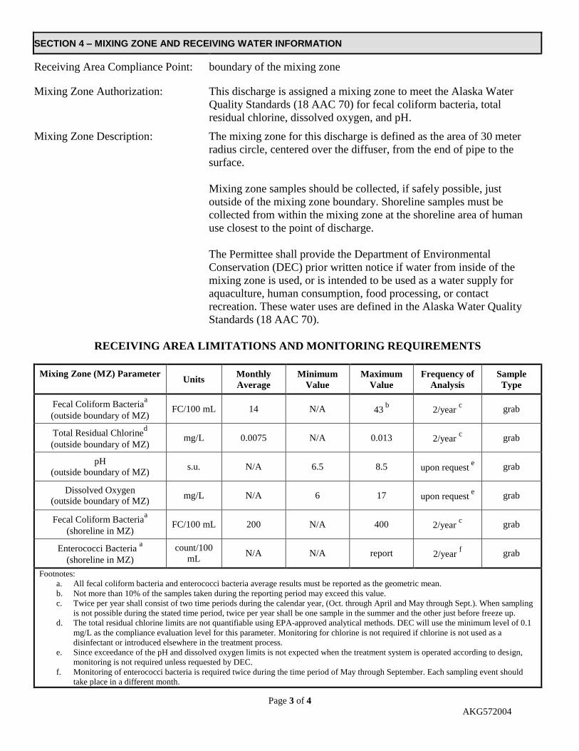
SECTION 4 – MIXING ZONE AND RECEIVING WATER INFORMATION
Receiving Area Compliance Point: boundary of the mixing zone
Mixing Zone Authorization: This discharge is assigned a mixing zone to meet the Alaska Water
Quality Standards (18 AAC 70) for fecal coliform bacteria, total
residual chlorine, dissolved oxygen, and pH.
Mixing Zone Description: The mixing zone for this discharge is defined as the area of 30 meter
radius circle, centered over the diffuser, from the end of pipe to the
surface.
Mixing zone samples should be collected, if safely possible, just
outside of the mixing zone boundary. Shoreline samples must be
collected from within the mixing zone at the shoreline area of human
use closest to the point of discharge.
The Permittee shall provide the Department of Environmental
Conservation (DEC) prior written notice if water from inside of the
mixing zone is used, or is intended to be used as a water supply for
aquaculture, human consumption, food processing, or contact
recreation. These water uses are defined in the Alaska Water Quality
Standards (18 AAC 70).
Page 4 of 4
AKG572004
SECTION 5 – SITE SPECIFIC REQUIREMENTS (In addition to those required in the APDES general permit.)
None
If you have any technical questions regarding this authorization or the requirements of the general permit,
please contact Sally Wanstall at (907) 465-5216 or [email protected].
SECTION 6 – CERTIFICATION/SIGNATURE
October 1, 2012
Signature Date
Brian Doyle Environmental Program Manager
Printed Name Title
Permit No. AKG572000 Page 2 of 13
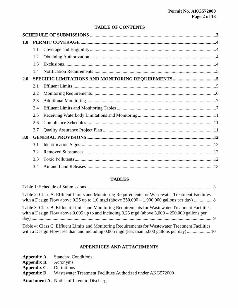
TABLE OF CONTENTS SCHEDULE OF SUBMISSIONS ............................................................................................................ 31.0 PERMIT COVERAGE .................................................................................................................... 4
1.1 Coverage and Eligibility ............................................................................................................ 41.2 Obtaining Authorization ............................................................................................................ 41.3 Exclusions .................................................................................................................................. 41.4 Notification Requirements ......................................................................................................... 5
2.0 SPECIFIC LIMITATIONS AND MONITORING REQUIREMENTS ..................................... 52.1 Effluent Limits ........................................................................................................................... 52.2 Monitoring Requirements .......................................................................................................... 62.3 Additional Monitoring ............................................................................................................... 72.4 Effluent Limits and Monitoring Tables ..................................................................................... 72.5 Receiving Waterbody Limitations and Monitoring ................................................................. 112.6 Compliance Schedules ............................................................................................................. 112.7 Quality Assurance Project Plan ............................................................................................... 11
3.0 GENERAL PROVISIONS ............................................................................................................. 123.1 Identification Signs .................................................................................................................. 123.2 Removed Substances ............................................................................................................... 123.3 Toxic Pollutants ....................................................................................................................... 123.4 Air and Land Releases ............................................................................................................. 13
TABLES
Table 1: Schedule of Submissions ............................................................................................................ 3
Table 2: Class A. Effluent Limits and Monitoring Requirements for Wastewater Treatment Facilities with a Design Flow above 0.25 up to 1.0 mgd (above 250,000 – 1,000,000 gallons per day) ................ 8
Table 3: Class B. Effluent Limits and Monitoring Requirements for Wastewater Treatment Facilities with a Design Flow above 0.005 up to and including 0.25 mgd (above 5,000 – 250,000 gallons per day) ........................................................................................................................................................... 9
Table 4: Class C. Effluent Limits and Monitoring Requirements for Wastewater Treatment Facilities with a Design Flow less than and including 0.005 mgd (less than 5,000 gallons per day) .................... 10
APPENDICES AND ATTACHMENTS
Appendix A. Standard Conditions Appendix B. Acronyms Appendix C. Definitions Appendix D. Wastewater Treatment Facilities Authorized under AKG572000
Attachment A. Notice of Intent to Discharge
Permit No. AKG572000 Page 3 of 13
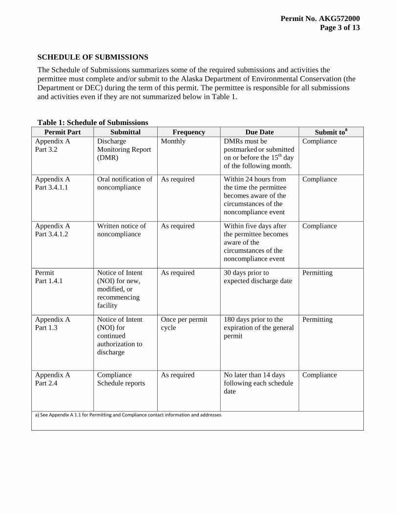
SCHEDULE OF SUBMISSIONS The Schedule of Submissions summarizes some of the required submissions and activities the permittee must complete and/or submit to the Alaska Department of Environmental Conservation (the Department or DEC) during the term of this permit. The permittee is responsible for all submissions and activities even if they are not summarized below in Table 1.
Table 1: Schedule of Submissions Permit Part Submittal Frequency Due Date Submit to
Appendix A
a
Part 3.2 Discharge Monitoring Report (DMR)
Monthly DMRs must be postmarked or submitted on or before the 15th
Compliance
day of the following month.
Appendix A Part 3.4.1.1
Oral notification of noncompliance
As required Within 24 hours from the time the permittee becomes aware of the circumstances of the noncompliance event
Compliance
Appendix A Part 3.4.1.2
Written notice of noncompliance
As required Within five days after the permittee becomes aware of the circumstances of the noncompliance event
Compliance
Permit Part 1.4.1
Notice of Intent (NOI) for new, modified, or recommencing facility
As required 30 days prior to expected discharge date
Permitting
Appendix A Part 1.3
Notice of Intent (NOI) for continued authorization to discharge
Once per permit cycle
180 days prior to the expiration of the general permit
Permitting
Appendix A Part 2.4
Compliance Schedule reports
As required No later than 14 days following each schedule date
Compliance
a) See Appendix A 1.1 for Permitting and Compliance contact information and addresses
Permit No. AKG572000 Page 4 of 13
1.0 PERMIT COVERAGE
1.1 Coverage and Eligibility Subject to the restrictions and conditions of this general permit, publicly owned treatment works (POTWs) and other treatment works that provide secondary treatment of domestic wastewater and discharging less than 1.0 million gallons per day (mgd) to fresh or marine surface water may be authorized to discharge the pollutants set out in part 2.0 of the general permit after receiving written authorization from DEC (part 1.2).
1.2 Obtaining Authorization
1.2.1 Authorization to discharge under this APDES general permit requires the responsible party of the facility seeking authorization to submit a completed notice of intent (NOI) to DEC in accordance with the requirements listed herein (part 1.4). The discharger must receive written notification of authorization from DEC that coverage has been granted and that a specific authorization number has been assigned to the operation prior to discharging.
1.2.2 The facilities listed in Appendix D are authorized to discharge under the conditions of this general permit without submittal of additional information to DEC and upon receipt of notification of authorization from DEC.
1.2.3 DEC may notify a discharger if their discharge is covered by this APDES general permit, even if the discharger has not submitted an NOI [18 AAC 83.210(h)].
1.3 Exclusions Dischargers meeting any of the following conditions will be excluded from coverage under this general permit. These specific permit conditions are more appropriately controlled under either a separate general or individual permit.
1.3.1 The design flow or actual discharge flow meets or exceeds 1.0 mgd.
1.3.2 A total maximum daily load (TMDL) analysis has been approved for the receiving water including waste load allocation(s) for the facility.
1.3.3 The receiving water is listed on the CWA Section 303(d) list as impaired for failure to meet a water quality standard (WQS) and the facility discharges a pollutant that causes or contributes to the impairment.
1.3.4 The wastewater treatment facility (WWTF) receives “significant contribution” from a non-domestic industrial user(s) as defined in Appendix C of this permit.
1.3.5 The discharge is from a single or two-family residential unit with a single, discrete outfall line. Such facilities must submit plans to DEC for review per 18 AAC 72.
1.3.6 The treatment facility is a common collector as defined in Appendix C of this general permit.
1.3.7 The treatment facility is an aerated or non-aerated lagoon.
1.3.8 The treatment facility discharges to tundra, land, subsurface, or wet areas that are not designated waters of the U.S.
Permit No. AKG572000 Page 5 of 13
1.4 Notification Requirements
1.4.1 Dischargers seeking authorization under this APDES general permit must submit a NOI to DEC at least 30 days before the date on which the discharge is to commence. The NOI may be submitted electronically via the Permit Application Portal at: http://dec.alaska.gov/water/wwdp/online_permitting/permitentry.htm. Facilities listed in Appendix D of the permit need not submit additional application information to DEC unless their originally submitted NOI on file requires modification or if they are requesting a different mixing zone.
1.4.2 If a mixing zone is requested, Form 2M must also be submitted with the NOI unless the facility is listed in Appendix D (see permit section 1.4.1). Form 2M can be found at:
http://dec.alaska.gov/water/wwdp/online_permitting/dom_ww_apps.htm
1.4.3 The applicant is strongly encouraged to use the NOI form included as Attachment A although other submittals deemed appropriate by the Department and that includes the information contained within the NOI will also satisfy the NOI requirements for coverage under this general permit.
1.4.4 The NOI must be signed by the responsible party in accordance with Signatory Requirements in Appendix A part 1.12 and submitted to the DEC address located in Appendix A part 1.1.1.
2.0 SPECIFIC LIMITATIONS AND MONITORING REQUIREMENTS
2.1 Effluent Limits
2.1.1 During the effective period of this general permit, the permittee is authorized to discharge wastewater provided the discharge meets the limits and monitoring requirements herein. This general permit does not authorize discharge of any waste streams, including spills and other unintentional or non-routine discharges of pollutants, not part of the normal operation of the facility as disclosed in the NOI.
2.1.2 The permittee must limit discharges as specified in one of the three tables in part 2.4 including facility specific limits identified in Appendix D. The applicable table is determined by the wastewater treatment facility design flow as outlined in part 2.2 of this general permit.
2.1.3 The discharge shall not cause contamination of surface or ground waters, and shall not cause a violation of the Alaska WQS (18 AAC 70), unless allowed in this permit through exceptions to the standards or in a compliance schedule. (18 AAC 70.200 – 70.270 and 18 AAC 70.910).
2.1.4 The permittee must collect influent samples prior to the waste stream flowing into the first treatment unit of the wastewater treatment system.
2.1.5 The permittee must collect effluent samples from the effluent stream after the last treatment unit before discharge into receiving waters.
Permit No. AKG572000 Page 6 of 13
2.1.6 For some facilities it may not be possible to determine the influent concentration of 5-day biochemical oxygen demand (BOD5
2.1.7 The permittee must orally report within 24 hours an exceedance of a fecal coliform bacteria, total residual chlorine, or dissolved oxygen maximum or minimum daily limit. See Appendix A, part 3.4 for additional reporting requirements.
) and total suspended solids (TSS). In those situations, the permittee shall contact DEC and alternatives that provide representative measurement may be approved.
2.2 Monitoring Requirements Monitoring frequencies required under this general permit are dependent on the WWTF design flow and are distinguished as follows:
Class A WWTFs with a design flow above 250,000 gallons per day (gpd) up to 1.0 mgd
Class B WWTFs with a design flow above 5,000 gpd up to and including 250,000 gpd
Class C WWTFs with a design flow less than and including 5,000 gpd
2.2.1 Unless otherwise noted, the permittee must use methods that can achieve a method detection limit (MDL) less than the effluent limit.
2.2.2 For purposes of reporting on the discharge monitoring report (DMR) for a single sample, if a value is less than MDL, the permittee must report “less than {numeric value of MDL}” and if a value is less than a minimum level (ML), the permittee must report “less than {numeric value of ML}.”
2.2.3 For purposes of calculating monthly averages, zero may be assigned for values less than the MDL and the numeric value of the MDL may be assigned for values between the MDL and the ML. If the average value is less than the MDL, the permittee must report “less than {numeric value of MDL}” and if the average value is less than the ML, the permittee must report “less than {numeric value of ML}.” If a value is equal to or greater than the ML, the permittee must report and use the actual value. The resulting average value must be compared to the compliance level in assessing compliance. Alternatively, the permittee may use one-half of the MDL as the assigned value for any data point that is reported less than the MDL when calculating monthly averages.
2.2.4 All facilities, with some exception for facilities that operate on a seasonal or non-continuous basis, must report monthly. DMRs shall be marked “no discharge” during months that the wastewater treatment facility is not discharging wastewater. If the discharge is seasonal, the permittee may indicate on the last monthly DMR of the season, the period when there will be no discharge. Monitoring reports will not be required for the months of indicated inactivity.
2.2.5 Permittees have the option of taking more frequent samples than are required under the permit. These samples must be used for averaging if they are conducted using the Department-approved test methods (generally found in 18 AAC 70 and 40 CFR §136 [adopted by reference in 18 AAC 83.010]) and if the MDLs are less than the effluent limits.
Permit No. AKG572000 Page 7 of 13
2.2.6 DEC may require additional effluent or ambient receiving waterbody monitoring for site specific purposes related to, but not limited to: application requirements, the protection of state WQS, gathering data to support TMDL development, evaluation of receiving water impairments, verification of mixing zone sizes, or evaluation of effects on threatened or endangered species. Likewise, monitoring frequency may be adjusted for site-specific purposes. The permittee will be notified of any additional or site-specific monitoring when issued authorization to discharge under this general permit.
2.2.7 The standard holding time for a fecal coliform or enterococci bacteria sample is 6 hours or 6 hours transport time if the analysis commences within 2 hours of sample receipt at the laboratory.
2.3 Additional Monitoring
2.3.1 Enterococci Bacteria All facilities discharging to marine water shall monitor for enterococci bacteria. See the fact sheet part 5.2 for further details.
2.3.2 Total Ammonia as Nitrogen
All facilities discharging above 250,000 gpd up to 1.0 mgd shall monitor for total ammonia as nitrogen for four years beginning in the second year of the permit and ending in the fifth year of the permit. The need for continued monitoring or limits shall be determined during the next reissuance of the general permit.. See the fact sheet part 5.3 for further details.
2.3.3 Temperature and pH Temperature and pH must be measured concurrently with total ammonia as nitrogen. See the fact sheet part 5.4 for further details.
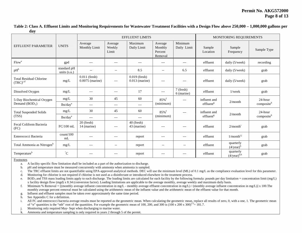
2.4 Effluent Limits and Monitoring Tables The permittee must limit and monitor discharges as specified in one of the following tables. The applicable table is determined by the design flow of the WWTF. The effluent limits must be met at the end of the treatment process, or for those facilities with modified limits, at the boundary of an authorized mixing zone. Facility specific effluent limits are contained in Appendix D. The permittee must comply with the effluent limits in the following tables at all times unless otherwise indicated, regardless of the frequency of monitoring or reporting required by other provisions of this general permit.
Permit No. AKG572000 Page 8 of 13
Table 2: Class A. Effluent Limits and Monitoring Requirements for Wastewater Treatment Facilities with a Design Flow above 250,000 – 1,000,000 gallons per day
EFFLUENT PARAMETER UNITS
EFFLUENT LIMITS MONITORING REQUIREMENTS
Average Monthly Limit
Average Weekly Limit
Maximum Daily Limit
Average Monthly Percent Removal
Minimum Daily Limit Sample
Location Sample
Frequency Sample Type
Flow gpd a --- --- --- --- --- effluent daily (5/week) recording
pH standard pH units (s.u.)
b -- -- 8.5 -- 6.5 effluent daily (5/week) grab
Total Residual Chlorine (TRC) mg/L c,d
0.011 (fresh) 0.0075 (marine)
--- 0.019 (fresh) 0.013 (marine)
--- --- effluent daily (5/week) grab
Dissolved Oxygen mg/L --- --- 17 --- 7 (fresh) 6 (marine) effluent 1/week grab
5-Day Biochemical Oxygen Demand (BOD5
mg/L )
30 45 60 85%(minimum)
f ---
influent and effluent 2/month g
24-hour compositelbs/day
h --- e --- ---
Total Suspended Solids (TSS)
mg/L 30 45 60 85%(minimum)
f ---
influent and effluent 2/month g
24-hour compositelbs/day
h --- e --- ---
Fecal Coliform Bacteria (FC) FC/100 mL
20 (fresh) 14 (marine)
--- 40 (fresh) 43 (marine)
--- --- effluent 2/month grab i
Enterococci Bacteria count/100 mL --- --- report --- --- effluent 1/month grab i,j
Total Ammonia as Nitrogen mg/L b --- -- report -- -- effluent quarterly (4/year) grab h
Temperatureb º --- C --- report --- --- effluent quarterly (4/year) grab h,k
a. A facility specific flow limitation shall be included as a part of the authorization to discharge. Footnotes
b. pH and temperature must be measured concurrently with ammonia when ammonia is sampled. c. The TRC effluent limits are not quantifiable using EPA-approved analytical methods. DEC will use the minimum level (ML) of 0.1 mg/L as the compliance evaluation level for this parameter. d. Monitoring for chlorine is not required if chlorine is not used as a disinfectant or introduced elsewhere in the treatment process. e. BOD5
f. Minimum % Removal = [(monthly average influent concentration in mg/L - monthly average effluent concentration in mg/L) / (monthly average influent concentration in mg/L)] x 100.The monthly average percent removal must be calculated using the arithmetric mean of the influent value and the arithmetric mean of the effluent value for that month.
and TSS mass loading limits apply to each discharge. The loading limits are calculated for each facility by the following formula: pounds per day limitation = concentration limit (mg/L) x facility design flow (mgd) x 8.34 (conversion factor). Loading limitations are applicable to the average monthly, average weekly and maximum daily basis.
g. Influent and effluent samples must be taken over approximately the same time period. h. See Appendix C for a definition. i. All FC and enterococci bacteria average results must be reported as the geometric mean. When calculating the geometric mean, replace all results of zero, 0, with a one, 1. The geometric mean
of “n” quantities is the “nth” root of the quantities. For example the geometric mean of 100, 200, and 300 is (100 x 200 x 300)1/3
j. Monitoring only required May- Sept when discharging to marine water. = 181.7.
k. Ammonia and temperature sampling is only required in years 2 through 5 of the permit.
Permit No. AKG572000 Page 9 of 13
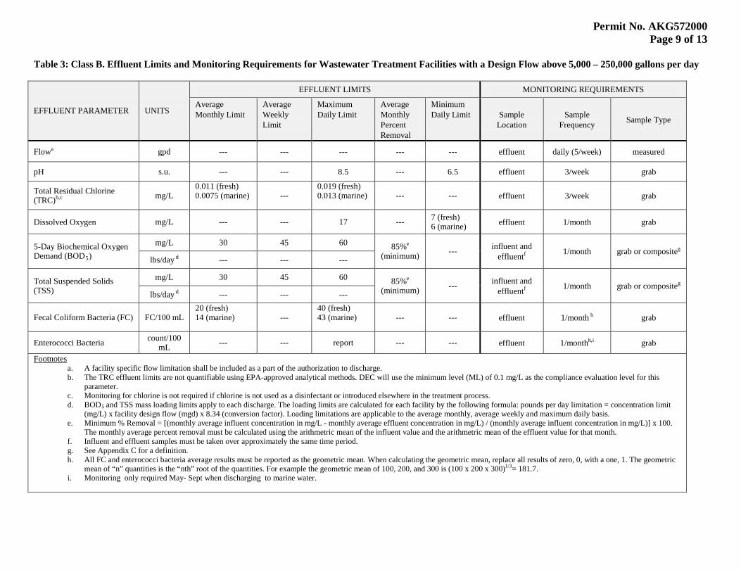
Table 3: Class B. Effluent Limits and Monitoring Requirements for Wastewater Treatment Facilities with a Design Flow above 5,000 – 250,000 gallons per day
EFFLUENT PARAMETER UNITS
EFFLUENT LIMITS MONITORING REQUIREMENTS
Average Monthly Limit
Average Weekly Limit
Maximum Daily Limit
Average Monthly Percent Removal
Minimum Daily Limit Sample
Location Sample
Frequency Sample Type
Flow gpd a --- --- --- --- --- effluent daily (5/week) measured
pH s.u. --- --- 8.5 --- 6.5 effluent 3/week grab
Total Residual Chlorine (TRC) mg/L b,c
0.011 (fresh) 0.0075 (marine)
--- 0.019 (fresh) 0.013 (marine)
--- --- effluent 3/week grab
Dissolved Oxygen mg/L --- --- 17 --- 7 (fresh) 6 (marine) effluent 1/month grab
5-Day Biochemical Oxygen Demand (BOD5
mg/L )
30 45 60 85%(minimum)
e --- influent and
effluent 1/month f grab or compositelbs/day
g
--- d --- ---
Total Suspended Solids (TSS)
mg/L 30 45 60 85%(minimum)
e --- influent and
effluent 1/month f grab or compositelbs/day
g --- d --- ---
Fecal Coliform Bacteria (FC) FC/100 mL 20 (fresh) 14 (marine)
--- 40 (fresh) 43 (marine)
--- --- effluent 1/month grab h
Enterococci Bacteria count/100 mL --- --- report --- --- effluent 1/month grab h,i
a. A facility specific flow limitation shall be included as a part of the authorization to discharge. Footnotes
b. The TRC effluent limits are not quantifiable using EPA-approved analytical methods. DEC will use the minimum level (ML) of 0.1 mg/L as the compliance evaluation level for this parameter.
c. Monitoring for chlorine is not required if chlorine is not used as a disinfectant or introduced elsewhere in the treatment process. d. BOD5
e. Minimum % Removal = [(monthly average influent concentration in mg/L - monthly average effluent concentration in mg/L) / (monthly average influent concentration in mg/L)] x 100. The monthly average percent removal must be calculated using the arithmetric mean of the influent value and the arithmetric mean of the effluent value for that month.
and TSS mass loading limits apply to each discharge. The loading limits are calculated for each facility by the following formula: pounds per day limitation = concentration limit (mg/L) x facility design flow (mgd) x 8.34 (conversion factor). Loading limitations are applicable to the average monthly, average weekly and maximum daily basis.
f. Influent and effluent samples must be taken over approximately the same time period. g. See Appendix C for a definition. h. All FC and enterococci bacteria average results must be reported as the geometric mean. When calculating the geometric mean, replace all results of zero, 0, with a one, 1. The geometric
mean of “n” quantities is the “nth” root of the quantities. For example the geometric mean of 100, 200, and 300 is (100 x 200 x 300)1/3
i. Monitoring only required May- Sept when discharging to marine water. = 181.7.
Permit No. AKG572000 Page 10 of 13
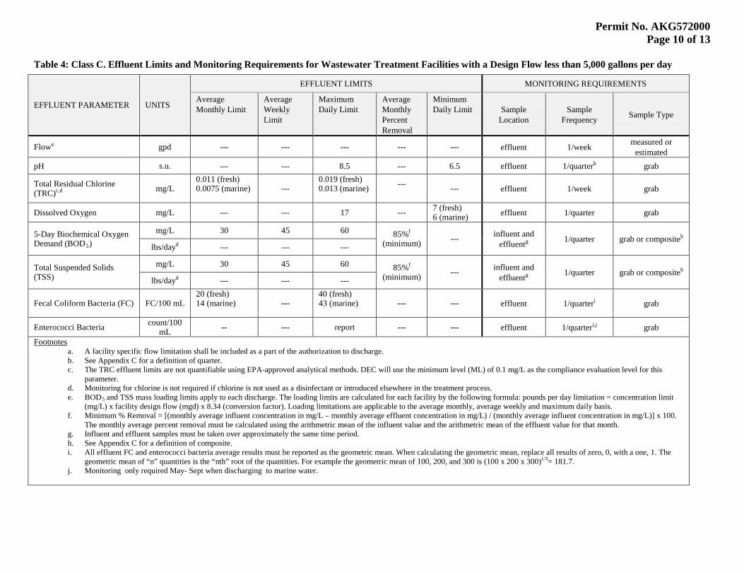
Table 4: Class C. Effluent Limits and Monitoring Requirements for Wastewater Treatment Facilities with a Design Flow less than 5,000 gallons per day
EFFLUENT PARAMETER UNITS
EFFLUENT LIMITS MONITORING REQUIREMENTS
Average Monthly Limit
Average Weekly Limit
Maximum Daily Limit
Average Monthly Percent Removal
Minimum Daily Limit Sample
Location Sample
Frequency Sample Type
Flow gpd a --- --- --- --- --- effluent 1/week measured or estimated
pH s.u. --- --- 8.5 --- 6.5 effluent 1/quarter grab b
Total Residual Chlorine (TRC) mg/L c,d
0.011 (fresh) 0.0075 (marine)
--- 0.019 (fresh) 0.013 (marine)
--- --- effluent 1/week grab
Dissolved Oxygen mg/L --- --- 17 --- 7 (fresh) 6 (marine) effluent 1/quarter grab
5-Day Biochemical Oxygen Demand (BOD5
mg/L )
30 45 60 85%(minimum)
f --- influent and
effluent 1/quarter g grab or compositelbs/day
h
--- d --- ---
Total Suspended Solids (TSS)
mg/L 30 45 60 85%(minimum)
f --- influent and
effluent 1/quarter g grab or compositelbs/day
h --- d --- ---
Fecal Coliform Bacteria (FC) FC/100 mL 20 (fresh) 14 (marine)
--- 40 (fresh) 43 (marine)
--- --- effluent 1/quarter grab i
Enterococci Bacteria count/100 mL -- --- report --- --- effluent 1/quarter grab i,j
a. A facility specific flow limitation shall be included as a part of the authorization to discharge. Footnotes
b. See Appendix C for a definition of quarter. c. The TRC effluent limits are not quantifiable using EPA-approved analytical methods. DEC will use the minimum level (ML) of 0.1 mg/L as the compliance evaluation level for this
parameter. d. Monitoring for chlorine is not required if chlorine is not used as a disinfectant or introduced elsewhere in the treatment process. e. BOD5
f. Minimum % Removal = [(monthly average influent concentration in mg/L – monthly average effluent concentration in mg/L) / (monthly average influent concentration in mg/L)] x 100. The monthly average percent removal must be calculated using the arithmetric mean of the influent value and the arithmetric mean of the effluent value for that month.
and TSS mass loading limits apply to each discharge. The loading limits are calculated for each facility by the following formula: pounds per day limitation = concentration limit (mg/L) x facility design flow (mgd) x 8.34 (conversion factor). Loading limitations are applicable to the average monthly, average weekly and maximum daily basis.
g. Influent and effluent samples must be taken over approximately the same time period. h. See Appendix C for a definition of composite. i. All effluent FC and enterococci bacteria average results must be reported as the geometric mean. When calculating the geometric mean, replace all results of zero, 0, with a one, 1. The
geometric mean of “n” quantities is the “nth” root of the quantities. For example the geometric mean of 100, 200, and 300 is (100 x 200 x 300)1/3
j. Monitoring only required May- Sept when discharging to marine water. = 181.7.
Permit No. AKG572000 Page 11 of 13
2.5 Receiving Waterbody Limitations and Monitoring
2.5.1 In accordance with 18 AAC 70.240, as amended through June 23, 2003, DEC may authorize a mixing zone. Permittees may request modifications to fecal coliform bacteria, total residual chlorine, dissolved oxygen, and pH effluent limits pursuant to 18 AAC 70.260. Form 2M may be used for this purpose. Form 2M can be found at: http://dec.alaska.gov/water/wwdp/online_permitting/dom_ww_apps.htm
DEC will approve modified effluent limits and a mixing zone if the modified limits and resulting mixing zone are consistent with the CWA and the mixing zone criteria at 18 AAC 70.240 through 18 AAC 70.270. The burden of proof for justifying a mixing zone rests with the applicant. See Appendix A of the fact sheet for the mixing zone criteria.
2.5.2 The facilities listed in Appendix D Table A have previously designated mixing zones. The parameters and sizes of the mixing zones for these facilities may be modified by DEC on a case-by-case basis.
2.5.3 The receiving area compliance point for permittees with an authorized mixing zone shall be at the outer boundary of the specified mixing zone. DEC may require monitoring at the shoreline if the mixing zone area contacts a shoreline. Specific requirements shall be outlined in the authorization to discharge.
2.5.4 The Permittee shall provide DEC written notice if water from inside of the mixing zone is used, or is intended to be used as a water supply for aquaculture, human consumption, food processing, or contact recreation. These water uses are defined in the Alaska WQS (18 AAC 70).
2.6 Compliance Schedules Per 18 AAC 70.910, the Department has the authority to issue schedules in permit, certifications, or approvals.
2.7 Quality Assurance Project Plan
2.7.1 Permittees must develop and implement a quality assurance project plan (QAPP) for all monitoring required by this permit. The QAPP must be developed and implemented within 180 days of receiving authorization under this general permit. Any existing QAPP may be modified under this section.
2.7.2 The QAPP must be designed to assist in planning for the collection and analysis of effluent and receiving water samples in support of the permit and to help explain data anomalies whenever they occur.
2.7.3 Permittees may use either the generic DEC QAPP, or develop a facility-specific QAPP. There is some facility specific information that is still required in order to complete the QAPP when using the generic DEC QAPP.
Permit No. AKG572000 Page 12 of 13
2.7.4 Throughout all sample collection and analysis activities, the permittees must use DEC-approved Quality Assurance/Quality Control and chain-of-custody procedures as described in the Requirements for Quality Assurance Project Plans (EPA/QA/R-5) and Guidance for Quality Assurance Project Plans (EPA/QA/G-5). The QAPP must be prepared in the format specified in these documents.
2.7.5 At a minimum, a facility-specific QAPP must include:
2.7.5.1 Details on number of samples, type of sample containers, preservation of samples, holding times, analytical methods, analytical detection and quantitation limits for each target compound, type and number of quality assurance field samples, precision and accuracy requirements, sample preparation requirements, sample shipping methods, and laboratory data delivery requirements.
2.7.5.2 Maps indicating the location of each sampling point.
2.7.5.3 Qualification and training of personnel.
2.7.5.4 Name, address and telephone number of all laboratories used by or proposed to be used by the permittee.
2.7.6 Permittee must amend the facility-specific QAPP whenever sample collection, sample analysis, or other procedure addressed by the QAPP is modified.
2.7.7 Copies of the QAPP must be kept on site and made available to DEC upon request.
3.0 GENERAL PROVISIONS
3.1 Identification Signs At least one sign must be posted on the shoreline near the discharge area during discharge. Signs must inform the public that secondary treated domestic wastewater is being discharged, state that there is a mixing zone (if applicable) and describe it, warn users of the area to exercise caution, and provide the phone number and identity of the discharger.
3.2 Removed Substances Collected screenings, grit, solids, scum, and other facility residuals, or other pollutants removed in the course of treatment or control of water and wastewaters shall be disposed of in a DEC-approved manner and method in accordance with 18 AAC 60, such as to prevent any pollution from such materials from entering navigable waters.
3.3 Toxic Pollutants The permittee must comply with effluent standards or prohibitions established under Section 307(a) of the Act and 18 AAC 70 for toxic pollutants within the time provided in the regulations that establish those standards or prohibitions, even if the permit has not yet been modified to incorporate the requirement.
Permit No. AKG572000 Page 13 of 13
3.4 Air and Land Releases The permittee must not place, deposit, or allow to be placed or deposited on the premises, any material which may produce, cause or contribute to the spread of disease, create a safety hazard or in any way endanger the health of the public.

APPENDIX A
Standard Conditions
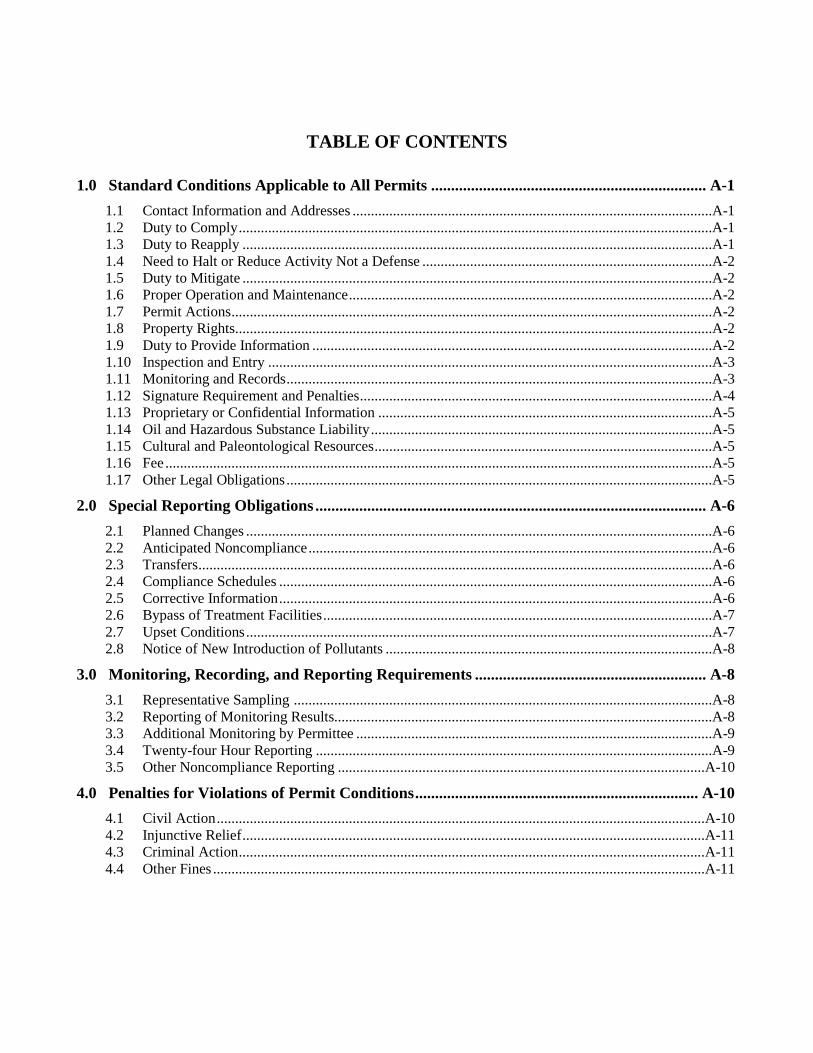
TABLE OF CONTENTS
1.0 Standard Conditions Applicable to All Permits ..................................................................... A-1
1.1 Contact Information and Addresses ..................................................................................................A-1 1.2 Duty to Comply .................................................................................................................................A-1 1.3 Duty to Reapply ................................................................................................................................A-1 1.4 Need to Halt or Reduce Activity Not a Defense ...............................................................................A-2 1.5 Duty to Mitigate ................................................................................................................................A-2 1.6 Proper Operation and Maintenance ...................................................................................................A-2 1.7 Permit Actions ...................................................................................................................................A-2 1.8 Property Rights ..................................................................................................................................A-2 1.9 Duty to Provide Information .............................................................................................................A-2 1.10 Inspection and Entry .........................................................................................................................A-3 1.11 Monitoring and Records ....................................................................................................................A-3 1.12 Signature Requirement and Penalties ................................................................................................A-4 1.13 Proprietary or Confidential Information ...........................................................................................A-5 1.14 Oil and Hazardous Substance Liability .............................................................................................A-5 1.15 Cultural and Paleontological Resources ............................................................................................A-5 1.16 Fee .....................................................................................................................................................A-5 1.17 Other Legal Obligations ....................................................................................................................A-5
2.0 Special Reporting Obligations .................................................................................................. A-6
2.1 Planned Changes ...............................................................................................................................A-6 2.2 Anticipated Noncompliance ..............................................................................................................A-6 2.3 Transfers ............................................................................................................................................A-6 2.4 Compliance Schedules ......................................................................................................................A-6 2.5 Corrective Information ......................................................................................................................A-6 2.6 Bypass of Treatment Facilities ..........................................................................................................A-7 2.7 Upset Conditions ...............................................................................................................................A-7 2.8 Notice of New Introduction of Pollutants .........................................................................................A-8
3.0 Monitoring, Recording, and Reporting Requirements .......................................................... A-8
3.1 Representative Sampling ..................................................................................................................A-8 3.2 Reporting of Monitoring Results.......................................................................................................A-8 3.3 Additional Monitoring by Permittee .................................................................................................A-9 3.4 Twenty-four Hour Reporting ............................................................................................................A-9 3.5 Other Noncompliance Reporting .................................................................................................... A-10
4.0 Penalties for Violations of Permit Conditions ....................................................................... A-10
4.1 Civil Action ..................................................................................................................................... A-10 4.2 Injunctive Relief .............................................................................................................................. A-11 4.3 Criminal Action ............................................................................................................................... A-11 4.4 Other Fines ...................................................................................................................................... A-11
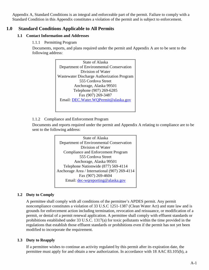
A-1
Appendix A, Standard Conditions is an integral and enforceable part of the permit. Failure to comply with a Standard Condition in this Appendix constitutes a violation of the permit and is subject to enforcement.
1.0 Standard Conditions Applicable to All Permits 1.1 Contact Information and Addresses
1.1.1 Permitting Program Documents, reports, and plans required under the permit and Appendix A are to be sent to the following address:
1.1.2 Compliance and Enforcement Program Documents and reports required under the permit and Appendix A relating to compliance are to be sent to the following address:
1.2 Duty to Comply A permittee shall comply with all conditions of the permittee’s APDES permit. Any permit noncompliance constitutes a violation of 33 U.S.C 1251-1387 (Clean Water Act) and state law and is grounds for enforcement action including termination, revocation and reissuance, or modification of a permit, or denial of a permit renewal application. A permittee shall comply with effluent standards or prohibitions established under 33 U.S.C. 1317(a) for toxic pollutants within the time provided in the regulations that establish those effluent standards or prohibitions even if the permit has not yet been modified to incorporate the requirement.
1.3 Duty to Reapply If a permittee wishes to continue an activity regulated by this permit after its expiration date, the permittee must apply for and obtain a new authorization. In accordance with 18 AAC 83.105(b), a
State of Alaska Department of Environmental Conservation
Division of Water Wastewater Discharge Authorization Program
555 Cordova Street Anchorage, Alaska 99501 Telephone (907) 269-6285
Fax (907) 269-3487 Email: [email protected]
State of Alaska Department of Environmental Conservation
Division of Water Compliance and Enforcement Program
555 Cordova Street Anchorage, Alaska 99501
Telephone Nationwide (877) 569-4114 Anchorage Area / International (907) 269-4114
Fax (907) 269-4604 Email: [email protected]
A-2
permittee with a currently effective a shall reapply by submitting a new application at least 180 days before the existing permit expires, unless the Department has granted the permittee permission to submit an application on a later date. However, the Department will not grant permission for an application to be submitted after the expiration date of the existing permit.
1.4 Need to Halt or Reduce Activity Not a Defense In an enforcement action, a permittee may not assert as a defense that compliance with the conditions of the permit would have made it necessary for the permittee to halt or reduce the permitted activity.
1.5 Duty to Mitigate A permittee shall take all reasonable steps to minimize or prevent any discharge in violation of this permit that has a reasonable likelihood of adversely affecting human health or the environment.
1.6 Proper Operation and Maintenance 1.6.1 A permittee shall at all times properly operate and maintain all facilities and systems of
treatment and control and related appurtenances that the permittee installs or uses to achieve compliance with the conditions of the permit. The permittee’s duty to operate and maintain properly includes using adequate laboratory controls and appropriate quality assurance procedures. However, a permittee is not required to operate back-up or auxiliary facilities or similar systems that a permittee installs unless operation of those facilities is necessary to achieve compliance with the conditions of the permit.
1.6.2 Operation and maintenance records shall be retained and made available at the site. 1.6.3 In accordance with 18 AAC 72.065, the owner of operator of a domestic system that has 100
or more service connections or that is used, or intended for use, by 500 or more people per day shall ensure that the system is operated by a person certified under 18 AAC 74.
1.7 Permit Actions A permit may be modified, revoked and reissued, or terminated for cause as provided in 18 AAC 83.130. If a permittee files a request to modify, revoke and reissue, or terminate a permit, or gives notice of planned changes or anticipated noncompliance, the filing or notice does not stay any permit condition.
1.8 Property Rights A permit does not convey any property rights or exclusive privilege.
1.9 Duty to Provide Information A permittee shall, within a reasonable time, provide to the Department any information that the Department requests to determine whether a permittee is in compliance with the permit, or whether cause exists to modify, revoke and reissue, or terminate the permit. A permittee shall also provide to the Department, upon request, copies of any records the permittee is required to keep under the permit.
A-3
1.10 Inspection and Entry A permittee shall allow the Department, or an authorized representative, including a contractor acting as a representative of the Department, at reasonable times and on presentation of credentials establishing authority and any other documents required by law, to:
1.10.1 Enter the premises where a permittee’s regulated facility or activity is located or conducted, or where permit conditions require records to be kept;
1.10.2 Have access to and copy any records that permit conditions require the permittee to keep; 1.10.3 Inspect any facilities, equipment, including monitoring and control equipment, practices, or
operations regulated or required under a permit; and 1.10.4 Sample or monitor any substances or parameters at any location for the purpose of assuring
permit compliance or as otherwise authorized by 33 U.S.C. 1251-1387 (Clean Water Act).
1.11 Monitoring and Records A permittee must comply with the following monitoring and recordkeeping conditions:
1.11.1 Samples and measurements taken for the purpose of monitoring must be representative of the monitored activity.
1.11.2 The permittee shall retain records in Alaska of all monitoring information for at least three years, or longer at the Department’s request at any time, from the date of the sample, measurement, report, or application. Monitoring records required to be kept include:
1.11.2.1 All calibration and maintenance records,
1.11.2.2 All original strip chart recordings or other forms of data approved by the Department for continuous monitoring instrumentation,
1.11.2.3 All reports required by a permit,
1.11.2.4 Records of all data used to complete the application for a permit,
1.11.2.5 Field logbooks or visual monitoring logbooks,
1.11.2.6 Quality assurance chain of custody forms,
1.11.2.7 Copies of discharge monitoring reports, and
1.11.2.8 A copy of this APDES permit.
1.11.3 Records of monitoring information must include:
1.11.3.1 The date, exact place, and time of any sampling or measurement;
1.11.3.2 The name(s) of any individual(s) who performed the sampling or measurement(s);
1.11.3.3 The date(s) and time any analysis was performed;
1.11.3.4 The name(s) of any individual(s) who performed any analysis;
1.11.3.5 Any analytical technique or method used; and
1.11.3.6 The results of the analysis.
1.11.4 Monitoring Procedures
Analyses of pollutants must be conducted using test procedures approved under 40 CFR Part 136, adopted by reference at 18 AAC 83.010, for pollutants with approved test procedures, and using test procedures specified in the permit for pollutants without approved methods.
A-4
1.12 Signature Requirement and Penalties
1.12.1 Any application, report, or information submitted to the Department in compliance with a permit requirement must be signed and certified in accordance with 18 AAC 83.385. Any person who knowingly makes any false material statement, representation, or certification in any application, record, report, or other document filed or required to be maintained under a permit, or who knowingly falsifies, tampers with, or renders inaccurate any monitoring device or method required to be maintained under this permit shall, upon conviction, be subject to penalties under 33 U.S.C. 1319(c)(4), AS 12.55.035(c)(1)(B), (c)(2) and (c)(3), and AS 46.03.790(g).
1.12.2 In accordance with 18 AAC 83.385, an APDES permit application must be signed as follows:
1.12.2.1 For a corporation, by a responsible corporate officer.
1.12.2.2 For a partnership or sole proprietorship, by the general partner or the proprietor, respectively.
1.12.2.3 For a municipality, state, federal, or other public agency, by either a principal executive officer or ranking elected official.
1.12.3 Any report required by an APDES permit, and a submittal with any other information requested by the Department, must be signed by a person described in Appendix A, Part 1.12.2, or by a duly authorized representative of that person. A person is a duly authorized representative only if:
1.12.3.1 The authorization is made in writing by a person described in Appendix A, Part 1.12.2;
1.12.3.2 The authorization specifies either an individual or a position having responsibility for the overall operation of the regulated facility or activity, including the position of plant manager, operator of a well or a well field, superintendent, or position of equivalent responsibility; or an individual or position having overall responsibility for environmental matters for the company; and
1.12.3.3 The written authorization is submitted to the Department to the Permitting Program address in Appendix A, Part 1.1.1.
1.12.4 If an authorization under Appendix A, Part 1.12.3 is no longer effective because a different individual or position has responsibility for the overall operation of the facility, a new authorization satisfying the requirements of Appendix A, Part 1.12.3 must be submitted to the Department before or together with any report, information, or application to be signed by an authorized representative.
1.12.5 Any person signing a document under Appendix A, Part 1.12.2 or Part 1.12.3 shall certify as follows:
"I certify under penalty of law that this document and all attachments were prepared under my direction or supervision in accordance with a system designed to assure that qualified personnel properly gather and evaluate the information submitted. Based on my inquiry of the person or persons who manage the system, or those persons directly responsible for gathering the information, the information submitted is, to the best of my knowledge and belief, true, accurate, and complete. I am aware that there are significant penalties for submitting false information, including the possibility of fine and imprisonment for knowing violations."
A-5
1.13 Proprietary or Confidential Information 1.13.1 A permit applicant or permittee may assert a claim of confidentiality for proprietary or
confidential business information by stamping the words “confidential business information” on each page of a submission containing proprietary or confidential business information. The Department will treat the stamped submissions as confidential if the information satisfies the test in 40 CFR §2.208, adopted by reference at 18 AAC 83.010, and is not otherwise required to be made public by state law.
1.13.2 A claim of confidentiality under Appendix A, Part 1.13.1 may not be asserted for the name and address of any permit applicant or permittee, a permit application, a permit, effluent data, sewage sludge data, and information required by APDES or NPDES application forms provided by the Department, whether submitted on the forms themselves or in any attachments used to supply information required by the forms.
1.13.3 A permittee’s claim of confidentiality authorized under Appendix A, Part 1.13.1 is not waived if the Department provides the proprietary or confidential business information to the EPA or to other agencies participating in the permitting process. The Department will supply any information obtained or used in the administration of the state APDES program to the EPA upon request under 40 CFR §123.41, as revised as of July 1, 2005. When providing information submitted to the Department with a claim of confidentiality to the EPA, the Department will notify the EPA of the confidentiality claim. If the Department provides the EPA information that is not claimed to be confidential, the EPA may make the information available to the public without further notice.
1.14 Oil and Hazardous Substance Liability Nothing in this permit shall be construed to preclude the institution of any action or relieve a permittee from any responsibilities, liabilities, or penalties to which the permittee is or may be subject to under state laws addressing oil and hazardous substances.
1.15 Cultural and Paleontological Resources If cultural or paleontological resources are discovered because of this disposal activity, work that would disturb such resources is to be stopped, and the Office of History and Archaeology, a Division of Parks and Outdoor Recreation of the Alaska Department of Natural Resources (http://www.dnr.state.ak.us/parks/oha/), is to be notified immediately at (907) 269-8721.
1.16 Fee A permittee must pay the appropriate permit fee described in 18 AAC 72.
1.17 Other Legal Obligations This permit does not relieve the permittee from the duty to obtain any other necessary permits from the Department or from other local, state, or federal agencies and to comply with the requirements contained in any such permits. All activities conducted and all plan approvals implemented by the permittee pursuant to the terms of this permit shall comply with all applicable local, state, and federal laws and regulations.
A-6
2.0 Special Reporting Obligations
2.1 Planned Changes
2.1.1 The permittee shall give notice to the Department as soon as possible of any planned physical alteration or addition to the permitted facility if:
2.1.1.1 The alteration or addition may make the facility a “new source” under one or more of the criteria in 18 AAC 83.990(44); or
2.1.1.2 The alteration or addition could significantly change the nature or increase the quantity of pollutants discharged if those pollutants are not subject to effluent limitations in the permit or to notification requirements under 18 AAC 83.610.
2.1.2 If the proposed changes are subject to plan review, then the plans must be submitted at least 30 days before implementation of changes (see 18 AAC 15.020 and 18 AAC 72 for plan review requirements). Written approval is not required for an emergency repair or routine maintenance.
2.1.3 Written notice must be sent to the Permitting Program address in Appendix A, Part 1.1.1.
2.2 Anticipated Noncompliance 2.2.1 A permittee shall give seven days’ notice to the Department before commencing any
planned change in the permitted facility or activity that may result in noncompliance with permit requirements.
2.2.2 Written notice must be sent to the Compliance and Enforcement Program address in Appendix A, Part 1.1.2.
2.3 Transfers 2.3.1 A permittee may not transfer a permit for a facility or activity to any person except after
notice to the Department in accordance with 18 AAC 83.150. The Department may modify or revoke and reissue the permit to change the name of the permittee and incorporate such other requirements under 33 U.S.C. 1251-1387 (Clean Water Act) or state law.
2.3.2 Written notice must be sent to the Permitting Program address in Appendix A, Part 1.1.1.
2.4 Compliance Schedules 2.4.1 A permittee must submit progress or compliance reports on interim and final requirements in
any compliance schedule of a permit no later than 14 days following the scheduled date of each requirement.
2.4.2 Written notice must be sent to the Compliance and Enforcement Program address in Appendix A, Part 1.1.2.
2.5 Corrective Information
2.5.1 If a permittee becomes aware that it failed to submit a relevant fact in a permit application or submitted incorrect information in a permit application or in any report to the Department, the permittee shall promptly submit the relevant fact or the correct information.
2.5.2 Information must be sent to the Permitting Program address in Appendix A, Part 1.1.1.
A-7
2.6 Bypass of Treatment Facilities
2.6.1 Prohibition of Bypass
Bypass is prohibited. The Department may take enforcement action against a permittee for any bypass, unless:
2.6.1.1 The bypass was unavoidable to prevent loss of life, personal injury, or severe property damage;
2.6.1.2 There were no feasible alternatives to the bypass, including use of auxiliary treatment facilities, retention of untreated wastes, or maintenance during normal periods of equipment downtime. However, this condition is not satisfied if the permittee, in the exercise of reasonable engineering judgment, should have installed adequate back-up equipment to prevent a bypass that occurred during normal periods of equipment downtime or preventive maintenance; and
2.6.1.3 The permittee provides notice to the Department of a bypass event in the manner, as appropriate, under Appendix A, Part 2.6.2.
2.6.2 Notice of bypass
2.6.2.1 For an anticipated bypass, the permittee submits notice at least 10 days before the date of the bypass. The Department may approve an anticipated bypass, after considering its adverse effects, if the Department determines that it will meet the conditions of Appendix A, Parts 2.6.1.1 and 2.6.1.2.
2.6.2.2 For an unanticipated bypass, the permittee submits 24-hour notice, as required in 18 AAC 83.410(f) and Appendix A, Part 3.4, Twenty-four Hour Reporting.
2.6.2.3 Written notice must be sent to the Compliance and Enforcement Program address in Appendix A, Part 1.1.2.
2.6.3 Notwithstanding Appendix A, Part 2.6.1, a permittee may allow a bypass that:
2.6.3.1 Does not cause an effluent limitation to be exceeded, and
2.6.3.2 Is for essential maintenance to assure efficient operation.
2.7 Upset Conditions
2.7.1 In any enforcement action for noncompliance with technology-based permit effluent limitations, a permittee may claim upset as an affirmative defense. A permittee seeking to establish the occurrence of an upset has the burden of proof to show that the requirements of Appendix A, Part 2.7.2 are met.
2.7.2 To establish the affirmative defense of upset, the permittee must demonstrate, through properly signed, contemporaneous operating logs or other relevant evidence that:
2.7.2.1 An upset occurred and the permittee can identify the cause or causes of the upset;
2.7.2.2 The permitted facility was at the time being properly operated;
2.7.2.3 The permittee submitted 24-hour notice of the upset, as required in 18 AAC 83.410(f) and Appendix A, Part 3.4, Twenty-four Hour Reporting; and
2.7.2.4 The permittee complied with any mitigation measures required under 18 AAC 83.405(e) and Appendix A, Part 1.5, Duty to Mitigate.
A-8
2.7.3 Any determination made in administrative review of a claim that noncompliance was caused by upset, before an action for noncompliance is commenced, is not final administrative action subject to judicial review.
2.8 Notice of New Introduction of Pollutants
2.8.1 Any POTW shall provide adequate notice to the Department, including information on the quality and quantity of effluent introduced into the POTW, and any anticipated impact of the change on the quantity or quality of effluent to be discharged from the POTW as soon as the POTW has knowledge of a change, but no later than seven days in advance of any:
2.8.1.1 New introduction of pollutants into the POTW from an indirect discharger if that introduction of pollutants would be subject to 33 U.S.C 1311 or 33 U.S.C 1316 if the POTW directly discharged those pollutants, and
2.8.1.2 Substantial change in the volume or character of pollutants being introduced into that POTW by a source introducing pollutants into the POTW at the time of issuance of the permit.
2.8.2 Written notice must be sent to the Permitting Program address in Appendix A, Part 1.1.1.
3.0 Monitoring, Recording, and Reporting Requirements 3.1 Representative Sampling
A permittee must collect effluent samples from the effluent stream after the last treatment unit before discharge into the receiving waters. Samples and measurements must be representative of the volume and nature of the monitored activity or discharge.
3.2 Reporting of Monitoring Results At intervals specified in the permit, monitoring results must be reported on the EPA discharge monitoring report (DMR) form, as revised as of March 1999, adopted by reference.
3.2.1 Monitoring results shall be summarized each month on the DMR or an approved equivalent report. The permittee must submit reports monthly postmarked by the 15th day of the following month.
3.2.2 The permittee must sign and certify all DMRs and all other reports in accordance with the requirements of Appendix A, Part 1.12, Signatory Requirements and Penalties. All signed and certified legible original DMRs and all other documents and reports must be submitted to the Department at the Compliance and Enforcement Program address in Appendix A, Part 1.1.2.
3.2.3 If, during the period when this permit is effective, the Department makes available electronic reporting, the permittee may, as an alternative to the requirements of Appendix A, Part 3.2.2, submit monthly DMRs electronically by the 15th day of the following month in accordance with guidance provided by the Department. The permittee must certify all DMRs and other reports, in accordance with the requirements of Appendix A, Part 1.12, Signatory Requirements and Penalties. The permittee must retain the legible originals of these documents and make them available to the Department upon request.
A-9
3.3 Additional Monitoring by Permittee If the permittee monitors any pollutant more frequently than the permit requires using test procedures approved in 40 CFR Part 136, adopted by reference at 18 AAC 83.010, or as specified in this permit, the results of that additional monitoring must be included in the calculation and reporting of the data submitted in the DMR required by Appendix A, Part 3.2. All limitations that require averaging of measurements must be calculated using an arithmetic means unless the Department specifies another method in the permit. Upon request by the Department, the permittee must submit the results of any other sampling and monitoring regardless of the test method used.
3.4 Twenty-four Hour Reporting
A permittee shall report any noncompliance event that may endanger health or the environment as follows:
3.4.1 A report must be made:
3.4.1.1 Orally within 24 hours after the permittee becomes aware of the circumstances, and
3.4.1.2 In writing within five days after the permittee becomes aware of the circumstances.
3.4.2 A report must include the following information:
3.4.2.1 A description of the noncompliance and its causes, including the estimated volume or weight and specific details of the noncompliance;
3.4.2.2 The period of noncompliance, including exact dates and times;
3.4.2.3 If the noncompliance has not been corrected, a statement regarding the anticipated time the noncompliance is expected to continue; and
3.4.2.4 Steps taken or planned to reduce, eliminate, and prevent reoccurrence of the noncompliance.
3.4.3 An event that must be reported within 24 hours includes:
3.4.3.1 An unanticipated bypass that exceeds any effluent limitation in the permit (see Appendix A, Part 2.6, Bypass of Treatment Facilities).
3.4.3.2 An upset that exceeds any effluent limitation in the permit (see Appendix A, Part 2.7, Upset Conditions).
3.4.3.3 A violation of a maximum daily discharge limitation for any of the pollutants listed in the permit as requiring 24-hour reporting.
3.4.4 The Department may waive the written report on a case-by-case basis for reports under Appendix A, Part 3.4 if the oral report has been received within 24 hours of the permittee becoming aware of the noncompliance event.
3.4.5 The permittee may satisfy the written reporting submission requirements of Appendix A, Part 3.4.1.2 by submitting the written report via email, if the following conditions are met:
3.4.5.1 The Noncompliance Notification Form or equivalent form is used to report the noncompliance;
3.4.5.2 The written report includes all the information required under Appendix A, Part 3.4.2;
3.4.5.3 The written report is properly certified and signed in accordance with Appendix A, Parts 1.12.3 and 1.12.5.;
A-10
3.4.5.4 The written report is scanned as a PDF (portable document format) document and transmitted to the Department as an attachment to the email; and
3.4.5.5 The permittee retains in the facility file the original signed and certified written report and a printed copy of the conveying email.
3.4.6 The email and PDF written report will satisfy the written report submission requirements of this permit provided the email is received by the Department within five days after the time the permittee becomes aware of the noncompliance event, and the email and written report satisfy the criteria of Part 3.4.5. The email address to report noncompliance is: [email protected]
3.5 Other Noncompliance Reporting
A permittee shall report all instances of noncompliance not required to be reported under Appendix A, Parts 2.4 (Compliance Schedules), 3.3 (Additional Monitoring by Permittee), and 3.4 (Twenty-four Hour Reporting) at the time the permittee submits monitoring reports under Appendix A, Part 3.2 (Reporting of Monitoring Results). A report of noncompliance under this part must contain the information listed in Appendix A, Part 3.4.2 and be sent to the Compliance and Enforcement Program address in Appendix A, Part 1.1.2.
4.0 Penalties for Violations of Permit Conditions Alaska laws allow the State to pursue both civil and criminal actions concurrently. The following is a summary of Alaska law. The permittee should read the applicable statutes for further substantive and procedural details.
4.1 Civil Action Under AS 46.03.760(e), a person who violates or causes or permits to be violated a regulation, a lawful order of the Department, or a permit, approval, or acceptance, or term or condition of a permit, approval or acceptance issued under the program authorized by AS 46.03.020 (12) is liable, in a civil action, to the state for a sum to be assessed by the court of not less than $500 nor more than $100,000 for the initial violation, nor more than $10,000 for each day after that on which the violation continues, and that shall reflect, when applicable:
4.1.1 Reasonable compensation in the nature of liquated damages for any adverse environmental effects caused by the violation, that shall be determined by the court according to the toxicity, degradability, and dispersal characteristics of the substance discharged, the sensitivity of the receiving environment, and the degree to which the discharge degrades existing environmental quality;
4.1.2 Reasonable costs incurred by the state in detection, investigation, and attempted correction of the violation;
4.1.3 The economic savings realized by the person in not complying with the requirements for which a violation is charged; and
4.1.4 The need for an enhanced civil penalty to deter future noncompliance.
A-11
4.2 Injunctive Relief 4.2.1 Under AS 46.03.820, the Department can order an activity presenting an imminent or
present danger to public health or that would be likely to result in irreversible damage to the environment be discontinued. Upon receipt of such an order, the activity must be immediately discontinued.
4.2.2 Under AS 46.03.765, the Department can bring an action in Alaska Superior Court seeking to enjoin ongoing or threatened violations for Department-issued permits and Department statutes and regulations.
4.3 Criminal Action Under AS 46.03.790(h), a person is guilty of a Class A misdemeanor if the person negligently:
4.3.1 Violates a regulation adopted by the Department under AS 46.03.020(12); 4.3.2 Violates a permit issued under the program authorized by AS 46.03.020(12); 4.3.3 Fails to provide information or provides false information required by a regulation adopted
under AS 46.03.020(12); 4.3.4 Makes a false statement, representation, or certification in an application, notice, record,
report, permit, or other document filed, maintained, or used for purposes of compliance with a permit issued under or a regulation adopted under AS 46.03.020(12); or
4.3.5 Renders inaccurate a monitoring device or method required to be maintained by a permit issued or under a regulation adopted under AS 46.03.020(12).
4.4 Other Fines Upon conviction of a violation of a regulation adopted under AS 46.03.020(12), a defendant who is not an organization may be sentenced to pay a fine of not more than $10,000 for each separate violation (AS 46.03.790(g)). A defendant that is an organization may be sentenced to pay a fine not exceeding the greater of: (1) $200,000; (2) three times the pecuniary gain realized by the defendant as a result of the offense; or (3) three times the pecuniary damage or loss caused by the defendant to another, or the property of another, as a result of the offense (AS 12.55.035(c)(1)(B), (c)(2), and (c)(3)).
Appendix B Acronyms
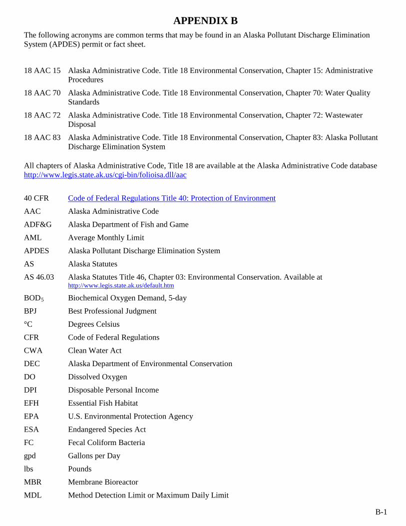
APPENDIX B
B-1
The following acronyms are common terms that may be found in an Alaska Pollutant Discharge Elimination System (APDES) permit or fact sheet.
18 AAC 15 Alaska Administrative Code. Title 18 Environmental Conservation, Chapter 15: Administrative Procedures
18 AAC 70 Alaska Administrative Code. Title 18 Environmental Conservation, Chapter 70: Water Quality Standards
18 AAC 72 Alaska Administrative Code. Title 18 Environmental Conservation, Chapter 72: Wastewater Disposal
18 AAC 83 Alaska Administrative Code. Title 18 Environmental Conservation, Chapter 83: Alaska Pollutant Discharge Elimination System
All chapters of Alaska Administrative Code, Title 18 are available at the Alaska Administrative Code database http://www.legis.state.ak.us/cgi-bin/folioisa.dll/aac
40 CFR Code of Federal Regulations Title 40: Protection of Environment
AAC Alaska Administrative Code
ADF&G
AML
Alaska Department of Fish and Game
Average Monthly Limit
APDES Alaska Pollutant Discharge Elimination System
AS Alaska Statutes
AS 46.03 Alaska Statutes Title 46, Chapter 03: Environmental Conservation. Available at http://www.legis.state.ak.us/default.htm
BOD Biochemical Oxygen Demand, 5-day 5
BPJ Best Professional Judgment
°C
CFR
Degrees Celsius
Code of Federal Regulations
CWA
DEC
Clean Water Act
Alaska Department of Environmental Conservation
DO
DPI
Dissolved Oxygen
Disposable Personal Income
EFH
EPA
Essential Fish Habitat
U.S. Environmental Protection Agency
ESA Endangered Species Act
FC
gpd
lbs
Fecal Coliform Bacteria
Gallons per Day
Pounds
MBR
MDL
Membrane Bioreactor
Method Detection Limit or Maximum Daily Limit
APPENDIX B
B-2
mg/L
mgd
ML
mL
NH
NH3
4
NOI
+
Milligrams per Liter
Million Gallons per Day
Minimum Level
Milliliter
Un-Ionized Ammonia
Ionized Ammonia
Notice of Intent
NMFS
NPDES
National Marine Fisheries Service
National Pollutant Discharge Elimination System
ODCE Ocean Discharge Criteria Evaluation
POTW Publicly Owned Treatment Works
QA Quality Assurance
QAPP Quality Assurance Project Plan
RPA Reasonable Potential Analysis
s.u.
TBEL
TMDL
TRC
TSS
µg/L
US
Standard Units
Technology Based Effluent Limit
Total Maximum Daily Load
Total Residual Chlorine
Total Suspended Solids
Micrograms per Liter
United States
U.S.C.
USFWS
WPCF
WQBEL
WQS
United States Code
United States Fish and Wildlife Service
Water Pollution Control Federation
Water Quality Based Effluent Limits
Water Quality Standards
WWTF Wastewater Treatment Facility

Appendix C Definitions
APPENDIX C
a) See 18 AAC 83 b) See 18 AAC 70.990 c) See 18 AAC 72.990 d) See 40 CFR Part 136 e) See EPA Technical Support Document f) See Standard Methods for the Examination of Water and Wastewater 18th Edition g) See EPA Permit Writers Manual
C-1
The following are common definitions of terms associated with APDES permits. Consult the footnote references for a complete list of terms and definitions.
Alaska Pollutant Discharge Elimination System (APDES)
Means the state’s program, approved by EPA under 33 U.S.C. 1342(b), for issuing, modifying, revoking and reissuing, terminating, monitoring and enforcing permits and imposing and enforcing pretreatment requirements under 33 U.S.C. 1317, 1328, 1342, and 1345
a
Anadromous Means a fish or fish species that spends portions of its life cycle in both fresh and salt waters, entering fresh water from the sea to spawn and includes the anadromous forms of pacific trouts and salmon of the genus Oncorhynchus (rainbow and cuththroat trout, and Chinook, coho, sockeye, chum, and pink salmon), Arctic char, Dolly Varden, sheefish, smelts, lamprey, whitefish, and sturgeon.
Aquaculture Means the cultivation of aquatic plants or animals for human use or consumption b
Average Means an arithmetic mean obtained by adding quantities and dividing the sum by the number of quantities
Average Monthly Limitation
Means the highest allowable average of “daily discharges” over a calendar month calculated as the sum of all “daily discharges” measured during a calendar month divided by the number of “daily discharges” measured for that month
a
Biochemical Oxygen Demand (BOD)
Means the amount, in milligrams per liter, of oxygen used in the biochemical oxidation of organic matter in five days at 20º C c
Boundary Means line or landmark that serves to clarify, outline, or mark a limit, border, or interface
b
Bypass Means the intentional diversion of waste streams from any portion of a treatment facility
a
Clean Water Act (CWA)
Means the federal law codified at 33 U.S.C. 1251-1387, also referred to as the Federal Water Pollution Control Act or Federal Water Pollution Control Act Amendments of 1972
a
Color Means the condition that results in the visual sensations of hue and intensity as measured after turbidity is removed
b
Commissioner Means the commissioner of the Alaska Department of Environmental Conservation or the commissioner’s designee
a
Common Collector Means more than one facility not under the same ownership using a common outfall line to discharge domestic wastewater
Composite Samples Composite samples must consist of at least eight equal volume grab samples. 24 hour composite sample means a combination of at least eight discrete samples of equal volume collected at equal time intervals over a 24-hour period at the same location. A "flow proportional composite" sample means a combination of at least eight discrete
APPENDIX C
a) See 18 AAC 83 b) See 18 AAC 70.990 c) See 18 AAC 72.990 d) See 40 CFR Part 136 e) See EPA Technical Support Document f) See Standard Methods for the Examination of Water and Wastewater 18th Edition g) See EPA Permit Writers Manual
C-2
samples collected at equal time intervals over a 24-hour period with each sample volume proportioned according to the flow volume. The sample aliquots must be collected and stored in accordance with procedures prescribed in the most recent edition of Standard Methods for the Examination of Water and Wastewater.
Contact Recreation Means activities in which there is direct and intimate contact with water. Contact recreation includes swimming, diving, and water skiing. Contact recreation does not include wading.
b
Criterion Means a set concentration or limit of a water quality parameter that, when not exceeded, will protect an organism, a population of organisms, a community of organisms, or a prescribed water use with a reasonable degree of safety. A criterion might be a narrative statement instead of a numerical concentration or limit.
b
Daily Discharge Means the discharge of a pollutant measured during a calendar day or any 24-hour period that reasonably represents the calendar day for the purposes of sampling. For pollutants measured in units of mass, the “daily discharge” is calculated as the total mass of the pollutant discharged over the day. For pollutants with a limitation expressed in other units of measurement, the “daily discharge” is calculated as the average measurement of the pollutant over the day.
a
Department Means the Alaska Department of Environmental Conservation a
Design Flow Means the wastewater flow rate that the plant was designed to handle a
Director Means the commissioner or the commissioner’s designee assigned to administer the APDES program or a portion of it, unless the context identifies an EPA director
a
Discharge When used without qualification, discharge means the discharge of a pollutant a
Discharge of a Pollutant
Means any addition of any pollutant or combination of pollutants to waters of the United States from any point source or to waters of the contiguous zone or the ocean from any point source other than a vessel or other floating craft that is being used as a means of transportation. Discharge includes any addition of pollutants into waters of the United States from surface runoff that is collected or channeled by humans; discharges through pipes, sewers, or other conveyances owned by a state, municipality, or other person that do not lead to a treatment works; discharges through pipes, sewers, or other conveyances leading into privately owned treatment works; and does not include an addition of pollutants by any indirect discharger.
a
Dissolved Oxygen (DO)
Means the concentration of oxygen in water as determined either by the Winkler (iodometric) method and its modifications or by the membrane electrode method. b
The oxygen dissolved in water or wastewater and usually expressed in milligrams per liter or percent saturation
Domestic Wastewater Means waterborne human wastes or graywater derived from dwellings, commercial buildings, institutions, or similar structures. "Domestic wastewater" includes the contents of individual removable containers used to collect and temporarily store human wastes.
c
APPENDIX C
a) See 18 AAC 83 b) See 18 AAC 70.990 c) See 18 AAC 72.990 d) See 40 CFR Part 136 e) See EPA Technical Support Document f) See Standard Methods for the Examination of Water and Wastewater 18th Edition g) See EPA Permit Writers Manual
C-3
Ecosystem Means a system made up of a community of animals, plants, and bacteria and the system’s interrelated physical and chemical environment
b
Effluent Means the segment of a wastewater stream that follows the final step in a treatment process and precedes discharge of the wastewater stream to the receiving environment
b
Estimated Means a way to estimate the discharge volume. Approvable estimations include, but are not limited to, the number of persons per day at the facility, volume of potable water produced per day, lift station run time, etc.
Eutrophication Means the process by which a body of water becomes enriched in dissolved nutrients that stimulate the growth of aquatic plant life usually resulting in the depletion of dissolved oxygen
Excluded area Means an area not authorized as a receiving water under a permit
Fecal Coliform Bacteria (FC)
Bacteria that can ferment lactose at 44.5° + 0.2°C to produce gas in a multiple tube procedure. Fecal coliform bacteria also means all bacteria that produce blue colonies in a membrane filtration procedure within 24 ± 2 hours of incubation at 44.5° + 0.2°C in an M-FC broth.
b
Final Approval to Operate
Means the approval that the Department issues after it has reviewed and approved the construction and operation of the engineered wastewater treatment works plans submitted to the Department in accordance with 18 AAC 72.215 through 18 AAC 72.280 or as amended
Geometric Mean The geometric mean is the Nth
559903423124 =xxx
root of the product of N. All sample results of zero will use a value of 1 for calculation of the geometric mean. Example geometric mean calculation: .
Grab Sample Means a single instantaneous sample collected at a particular place and time that represents the composition of wastewater only at that time and place
Influent Means untreated wastewater before it enters the first treatment process of a wastewater treatment works
Maximum Daily Discharge Limitation
Means the highest allowable “daily discharge” a
Mean Means the average of values obtained over a specified period and, for fecal coliform analysis, is computed as a geometric mean
b
Mean Lower Low Water
Means the tidal datum plane of the average of the lower of the two low waters of each day, as would be established by the National Geodetic Survey, at any place subject to tidal influence
b
Measured Means the actual volume of wastewater discharged using appropriate mechanical or electronic equipment to provide a totalized reading. Measure does not provide a recorded measurement of instantaneous rates.
APPENDIX C
a) See 18 AAC 83 b) See 18 AAC 70.990 c) See 18 AAC 72.990 d) See 40 CFR Part 136 e) See EPA Technical Support Document f) See Standard Methods for the Examination of Water and Wastewater 18th Edition g) See EPA Permit Writers Manual
C-4
Method Detection Limit (MDL)
Means the minimum concentration of a substance (analyte) that can be measured and reported with 99 percent confidence that the analyte concentration is greater than zero and is determined from analysis of a sample in a given matrix containing the analyte
d
Micrograms per Liter (µg/L)
Means the concentration at which one millionth of a gram (10b
-6
Milligrams per Liter (mg/L)
g) is found in a volume of one liter
Means the concentration at which one thousandth of a gram (10b
-3
Minimum Level (ML)
g) is found in a volume of one liter. It is approximately equal to the unit “parts per million (ppm),” formerly of common use.
Means the concentration at which the entire analytical system must give a recognizable signal and an acceptable calibration point. The ML is the concentration in a sample that is equivalent to the concentration of the lowest calibration standard analyzed by a specific analytical procedure, assuming that all the method-specified sample weights, volumes, and processing steps have been followed. This level is used as the compliance level if the effluent limit is below it.
e
Mixing Zone Means a volume of water adjacent to a discharge in which wastes discharged mix with the receiving water
b
Month Means the time period from the 1st
Monthly Average
of a calendar month to the last day in the month
Means the average of daily discharges over a monitoring month calculated as the sum of all daily discharges measured during a monitoring month divided by the number of daily discharges measured during that month
Permittee Means a company, organization, association, entity, or person who is issued a wastewater permit and is responsible for ensuring compliance, monitoring, and reporting as required by the permit
pH Means a measure of the hydrogen ion concentration of water or wastewater; expressed as the negative log of the hydrogen ion concentration in mg/L. A pH of 7 is neutral. A pH less than 7 is acidic, and a pH greater than 7 is basic.
g
Primary Contact Recreation
See Contact Recreation
Principal Executive Officer
Means the chief executive officer of the agency or a senior executive officer having responsibility for the overall operations of a principal geographic unit of division of the agency
a
Pollutant Means dredged spoil, solid waste, incinerator residue, filter backwash, sewage, garbage, sewage sludge, munitions, chemical wastes, biological materials, radioactive materials (except those regulated under 42 U.S.C. 2011), heat, wrecked or discarded equipment, rock, sand, cellar dirt, and industrial, municipal, or agricultural waste discharged into water
a
Quality Assurance Project Plan (QAPP)
Means a system of procedures, checks, audits, and corrective actions to ensure that all research design and performance, environmental monitoring and sampling, and other technical and reporting activities are of the highest achievable quality
APPENDIX C
a) See 18 AAC 83 b) See 18 AAC 70.990 c) See 18 AAC 72.990 d) See 40 CFR Part 136 e) See EPA Technical Support Document f) See Standard Methods for the Examination of Water and Wastewater 18th Edition g) See EPA Permit Writers Manual
C-5
Quarter Means the time period of three months based on the calendar year beginning with January
Receiving Water Body Means lakes, bays, sounds, ponds, impounding reservoirs, springs, wells, rivers, streams, creeks, estuaries, marshes, inlets, straits, passages, canals, the Pacific Ocean, Gulf of Alaska, Bering Sea, and Arctic Ocean, in the territorial limits of the state, and all other bodies of surface water, natural or artificial, public or private, inland or coastal, fresh or salt, which are wholly or partially in or bordering the state or under the jurisdiction of the state. (See “Waters of the U.S.” at 18 AAC 83.990(77))
Recorded Means a permanent record using mechanical or electronic equipment to provide a totalized reading, as well as a record of instantaneous readings
Report Report results of analysis
Residual Chlorine Means chlorine remaining in water or wastewater at the end of a specified contact period as combined or free chlorine
Responsible Corporate Officer
Means a president, secretary, treasurer, or vice-president of the corporation in charge of a principal business function or any other person who performs similar policy or decision making functions for the corporation
a
The Responsible Corporate Officer can also be the manager of one or more manufacturing, production, or operating facilities if the requirements of 18 AAC 83.385(a)(1)(B)(i)-(iii) are met.
Schedule of Compliance Means a schedule of remedial measures in a permit, including an enforceable sequence of interim requirements such as actions, operations, or milestone events, leading to compliance with 33 U.S.C. 1251-1387 and 18 AAC 83.
Secondary Recreation Means activities in which incidental water use can occur. Secondary recreation includes boating, camping, hunting, hiking, wading, and recreational fishing. Secondary contact recreation does not include fish consumption.
b
Settleable Solids Means solid material of organic or mineral origin that is transported by and deposited from water, as measured by the volumetric Imhoff cone method and at the method detection limits specified in method 2540(F), Standard Methods for the Examination of Water and Wastewater, 18th edition (1992), adopted by reference in 18 AAC 70.020(c)(1)
b
Severe Property Damage
Means substantial physical damage to property, damage to the treatment facilities which causes them to become inoperable, or substantial and permanent loss of natural resources which can reasonably be expected to occur in the absence of a bypass. Severe property damage does not mean economic loss caused by delays in production.
a
Sheen Means an iridescent appearance on the water surface b
Shellfish Means a species of crustacean, mollusk, or other aquatic invertebrate with a shell or shell-like exoskeleton in any stage of its life cycle
b
APPENDIX C
a) See 18 AAC 83 b) See 18 AAC 70.990 c) See 18 AAC 72.990 d) See 40 CFR Part 136 e) See EPA Technical Support Document f) See Standard Methods for the Examination of Water and Wastewater 18th Edition g) See EPA Permit Writers Manual
C-6
Significant Industrial User (SIU)
Means an indirect discharger that is the focus of control efforts under the national pretreatment program; includes all indirect dischargers subject to national categorical pretreatment standards, and all other indirect dischargers that contribute 25,000 gpd or more of process wastewater, or which make up five percent or more of the hydraulic or organic loading to the municipal treatment plant, subject to certain exceptions [40 CFR $403.3(t)].
g
Suspended Solids Means insoluble solids that either float on the surface of, or are in suspension in, water, wastewater, or other liquids. The quantity of material removed from wastewater in a laboratory test, as prescribed in Standard Methods for the Examination of Water and Wastewater and referred to as nonfilterable.
Total Maximum Daily Load (TMDL)
Means the sum of the individual waste load allocations (WLAs) and load allocations (LAS); a margin of safety is included with the two types of allocations so that any additional loading, regardless of source, would not produce a violation of water quality standards
Total Suspended Solids (TSS)
Means a measure of the filterable solids present in a sample, as determined by the method specified in 40 CFR Part 136 g
Twice per year Means two time periods during the calendar year: October through April and May through September
Upset Means an exceptional incident in which there is unintentional and temporary noncompliance with technology-based effluent limitations because of factors beyond the reasonable control of the permittee. An upset does not include noncompliance to the extent caused by operational error, improperly designed treatment facilities, inadequate treatment facilities, lack of preventive maintenance, or careless or improper operation.
a
Waste Load Allocation Means the portion of a receiving water's TMDL that is allocated to one of its existing or future point sources of pollution
Water Recreation See contact recreation or secondary recreation b
Water Supply Means any of the waters of the United States that are designated in 18 AAC 70 to be protected for fresh water or marine water uses. Water supply includes waters used for drinking, culinary, food processing, agricultural, aquacultural, seafood processing, and industrial purposes. Water supply does not necessarily mean that water in a waterbody that is protected as a supply for the uses listed in this paragraph is safe to drink in its natural state.
b
Wastewater Treatment Means any process to which wastewater is subjected in order to remove or alter its objectionable constituents and make it suitable for subsequent use or acceptable for discharge to the environment
Waters of the United States or Waters of the U.S.
Has the meaning given in 18 AAC 83.990(77)
Week Means the time period of Sunday through Saturday
Appendix D Wastewater Treatment Facilities Authorized under AKG572000
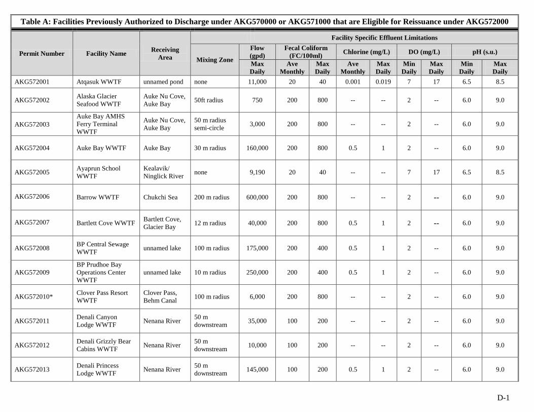
D-1
Table A: Facilities Previously Authorized to Discharge under AKG570000 or AKG571000 that are Eligible for Reissuance under AKG572000
Permit Number Facility Name Receiving Area
Facility Specific Effluent Limitations
Mixing Zone
Flow (gpd)
Fecal Coliform (FC/100ml) Chlorine (mg/L) DO (mg/L) pH (s.u.)
Max Daily
Ave Monthly
Max Daily
Ave Monthly
Max Daily
Min Daily
Max Daily
Min Daily
Max Daily
AKG572001 Atqasuk WWTF unnamed pond none 11,000 20 40 0.001 0.019 7 17 6.5 8.5
AKG572002 Alaska Glacier Seafood WWTF
Auke Nu Cove, Auke Bay 50ft radius 750 200 800 -- -- 2 -- 6.0 9.0
AKG572003 Auke Bay AMHS Ferry Terminal WWTF
Auke Nu Cove, Auke Bay
50 m radius semi-circle 3,000 200 800 -- -- 2 -- 6.0 9.0
AKG572004 Auke Bay WWTF Auke Bay 30 m radius 160,000 200 800 0.5 1 2 -- 6.0 9.0
AKG572005 Ayaprun School WWTF
Kealavik/ Ninglick River none 9,190 20 40 -- -- 7 17 6.5 8.5
AKG572006 Barrow WWTF Chukchi Sea 200 m radius 600,000 200 800 -- -- 2 -- 6.0 9.0
AKG572007 Bartlett Cove WWTF Bartlett Cove, Glacier Bay 12 m radius 40,000 200 800 0.5 1 2 -- 6.0 9.0
AKG572008 BP Central Sewage WWTF unnamed lake 100 m radius 175,000 200 400 0.5 1 2 -- 6.0 9.0
AKG572009 BP Prudhoe Bay Operations Center WWTF
unnamed lake 10 m radius 250,000 200 400 0.5 1 2 -- 6.0 9.0
AKG572010* Clover Pass Resort WWTF
Clover Pass, Behm Canal 100 m radius 6,000 200 800 -- -- 2 -- 6.0 9.0
AKG572011 Denali Canyon Lodge WWTF Nenana River 50 m
downstream 35,000 100 200 -- -- 2 -- 6.0 9.0
AKG572012 Denali Grizzly Bear Cabins WWTF Nenana River 50 m
downstream 10,000 100 200 -- -- 2 -- 6.0 9.0
AKG572013 Denali Princess Lodge WWTF Nenana River 50 m
downstream 145,000 100 200 0.5 1 2 -- 6.0 9.0
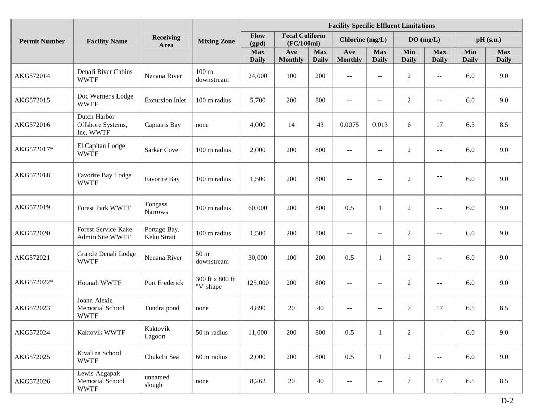
D-2
Permit Number Facility Name Receiving Area Mixing Zone
Facility Specific Effluent LimitationsFlow (gpd)
Fecal Coliform
(FC/100ml) Chlorine (mg/L) DO (mg/L) pH (s.u.)
Max Daily
Ave Monthly
Max Daily
Ave Monthly
Max Daily
Min Daily
Max Daily
Min Daily
Max Daily
AKG572014 Denali River Cabins WWTF Nenana River 100 m
downstream 24,000 100 200 -- -- 2 -- 6.0 9.0
AKG572015 Doc Warner's Lodge WWTF Excursion Inlet 100 m radius 5,700 200 800 -- -- 2 -- 6.0 9.0
AKG572016 Dutch Harbor Offshore Systems, Inc. WWTF
Captains Bay none 4,000 14 43 0.0075 0.013 6 17 6.5 8.5
AKG572017* El Capitan Lodge WWTF Sarkar Cove 100 m radius 2,000 200 800 -- -- 2 -- 6.0 9.0
AKG572018 Favorite Bay Lodge WWTF Favorite Bay 100 m radius 1,500 200 800 -- -- 2 -- 6.0 9.0
AKG572019 Forest Park WWTF Tongass Narrows 100 m radius 60,000 200 800 0.5 1 2 -- 6.0 9.0
AKG572020 Forest Service Kake Admin Site WWTF
Portage Bay, Keku Strait 100 m radius 1,500 200 800 -- -- 2 -- 6.0 9.0
AKG572021 Grande Denali Lodge WWTF Nenana River 50 m
downstream 30,000 100 200 0.5 1 2 -- 6.0 9.0
AKG572022* Hoonah WWTF Port Frederick 300 ft x 800 ft "V' shape 125,000 200 800 -- -- 2 -- 6.0 9.0
AKG572023 Joann Alexie Memorial School WWTF
Tundra pond none 4,890 20 40 -- -- 7 17 6.5 8.5
AKG572024 Kaktovik WWTF Kaktovik Lagoon 50 m radius 11,000 200 800 0.5 1 2 -- 6.0 9.0
AKG572025 Kivalina School WWTF Chukchi Sea 60 m radius 2,000 200 800 0.5 1 2 -- 6.0 9.0
AKG572026 Lewis Angapak Memorial School WWTF
unnamed slough none 8,262 20 40 -- -- 7 17 6.5 8.5
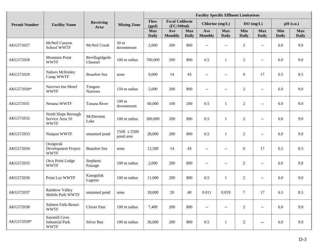
D-3
Permit Number Facility Name Receiving Area Mixing Zone
Facility Specific Effluent LimitationsFlow (gpd)
Fecal Coliform
(FC/100ml) Chlorine (mg/L) DO (mg/L) pH (s.u.)
Max Daily
Ave Monthly
Max Daily
Ave Monthly
Max Daily
Min Daily
Max Daily
Min Daily
Max Daily
AKG572027 McNeil Canyon School WWTF McNeil Creek 50 m
downstream 2,000 200 800 -- -- 2 -- 6.0 9.0
AKG572028 Mountain Point WWTF
Revillagidgedo Channel 100 m radius 700,000 200 800 0.5 1 2 -- 6.0 9.0
AKG572029 Nabors McKinley Camp WWTF Beaufort Sea none 9,000 14 43 -- -- 6 17 6.5 8.5
AKG572030* Narrows Inn Motel WWTF
Tongass Narrows 150 m radius 5,000 200 800 -- -- 2 -- 6.0 9.0
AKG572031 Nenana WWTF Tanana River 100 m downstream 60,000 100 200 0.5 1 2 -- 6.0 9.0
AKG572032 North Slope Borough Service Area 10 WWTF
McDermott Lake 100 m radius 300,000 200 800 0.5 1 2 -- 6.0 9.0
AKG572033 Nuiqsut WWTF unnamed pond 150ft x 250ft pond area 28,000 200 800 0.5 1 2 -- 6.0 9.0
AKG572034 Oooguruk Development Project WWTF
Beaufort Sea none 12,500 14 43 -- -- 6 17 6.5 8.5
AKG572035 Orca Point Lodge WWTF
Stephens Passage 100 m radius 2,000 200 800 -- -- 2 -- 6.0 9.0
AKG572036 Point Lay WWTF Kaseguluk Lagoon 100 m radius 11,000 200 800 0.5 1 2 -- 6.0 9.0
AKG572037 Rainbow Valley Mobile Park WWTF unnamed pond none 18,000 20 40 0.011 0.019 7 17 6.5 8.5
AKG572038 Salmon Falls Resort WWTF Clover Pass 100 m radius 7,400 200 800 -- -- 2 -- 6.0 9.0
AKG572039* Sawmill Cove Industrial Park WWTF
Silver Bay 100 m radius 36,000 200 800 0.5 1 2 -- 6.0 9.0
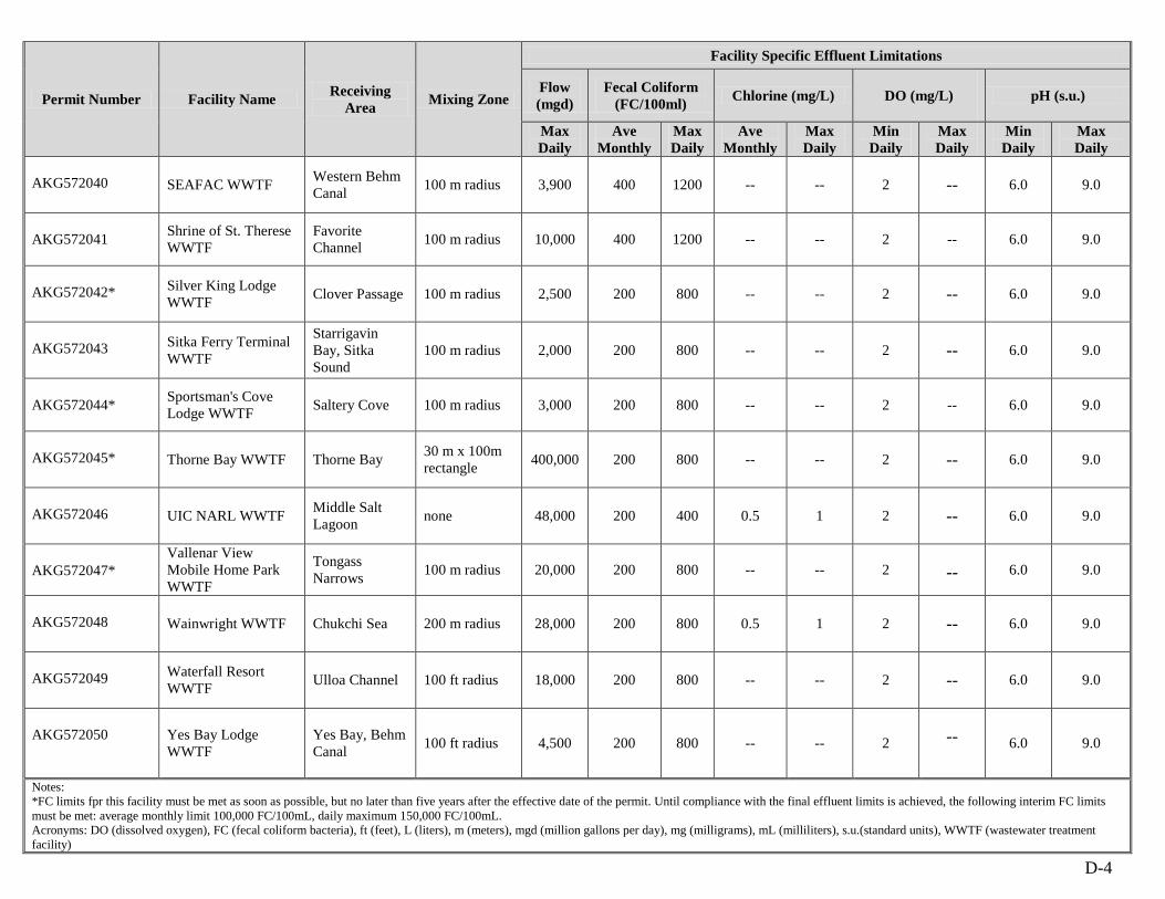
D-4
Permit Number Facility Name Receiving Area Mixing Zone
Facility Specific Effluent Limitations
Flow (mgd)
Fecal Coliform (FC/100ml) Chlorine (mg/L) DO (mg/L) pH (s.u.)
Max Daily
Ave Monthly
Max Daily
Ave Monthly
Max Daily
Min Daily
Max Daily
Min Daily
Max Daily
AKG572040 SEAFAC WWTF Western Behm Canal 100 m radius 3,900 400 1200 -- -- 2 -- 6.0 9.0
AKG572041 Shrine of St. Therese WWTF
Favorite Channel 100 m radius 10,000 400 1200 -- -- 2 -- 6.0 9.0
AKG572042* Silver King Lodge WWTF Clover Passage 100 m radius 2,500 200 800 -- -- 2 -- 6.0 9.0
AKG572043 Sitka Ferry Terminal WWTF
Starrigavin Bay, Sitka Sound
100 m radius 2,000 200 800 -- -- 2 -- 6.0 9.0
AKG572044* Sportsman's Cove Lodge WWTF Saltery Cove 100 m radius 3,000 200 800 -- -- 2 -- 6.0 9.0
AKG572045* Thorne Bay WWTF Thorne Bay 30 m x 100m rectangle 400,000 200 800 -- -- 2 -- 6.0 9.0
AKG572046 UIC NARL WWTF Middle Salt Lagoon none 48,000 200 400 0.5 1 2 -- 6.0 9.0
AKG572047* Vallenar View Mobile Home Park WWTF
Tongass Narrows 100 m radius 20,000 200 800 -- -- 2 -- 6.0 9.0
AKG572048 Wainwright WWTF Chukchi Sea 200 m radius 28,000 200 800 0.5 1 2 -- 6.0 9.0
AKG572049 Waterfall Resort WWTF Ulloa Channel 100 ft radius 18,000 200 800 -- -- 2 -- 6.0 9.0
AKG572050 Yes Bay Lodge WWTF
Yes Bay, Behm Canal 100 ft radius 4,500 200 800 -- -- 2 -- 6.0 9.0
Notes: *FC limits fpr this facility must be met as soon as possible, but no later than five years after the effective date of the permit. Until compliance with the final effluent limits is achieved, the following interim FC limits must be met: average monthly limit 100,000 FC/100mL, daily maximum 150,000 FC/100mL. Acronyms: DO (dissolved oxygen), FC (fecal coliform bacteria), ft (feet), L (liters), m (meters), mgd (million gallons per day), mg (milligrams), mL (milliliters), s.u.(standard units), WWTF (wastewater treatment facility)
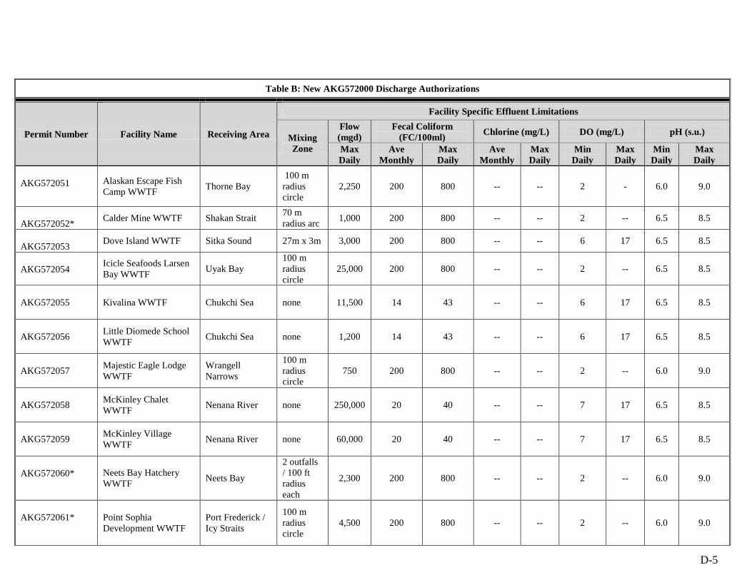
D-5
Table B: New AKG572000 Discharge Authorizations
Permit Number Facility Name Receiving Area
Facility Specific Effluent Limitations
Mixing Zone
Flow (mgd)
Fecal Coliform (FC/100ml) Chlorine (mg/L) DO (mg/L) pH (s.u.)
Max Daily
Ave Monthly
Max Daily
Ave Monthly
Max Daily
Min Daily
Max Daily
Min Daily
Max Daily
AKG572051 Alaskan Escape Fish Camp WWTF Thorne Bay
100 m radius circle
2,250 200 800 -- -- 2 - 6.0 9.0
AKG572052* Calder Mine WWTF Shakan Strait 70 m radius arc 1,000 200 800 -- -- 2 -- 6.5 8.5
AKG572053 Dove Island WWTF Sitka Sound 27m x 3m 3,000 200 800 -- -- 6 17 6.5 8.5
AKG572054 Icicle Seafoods Larsen Bay WWTF Uyak Bay
100 m radius circle
25,000 200 800 -- -- 2 -- 6.5 8.5
AKG572055 Kivalina WWTF Chukchi Sea none 11,500 14 43 -- -- 6 17 6.5 8.5
AKG572056 Little Diomede School WWTF Chukchi Sea none 1,200 14 43 -- -- 6 17 6.5 8.5
AKG572057 Majestic Eagle Lodge WWTF
Wrangell Narrows
100 m radius circle
750 200 800 -- -- 2 -- 6.0 9.0
AKG572058 McKinley Chalet WWTF Nenana River none 250,000 20 40 -- -- 7 17 6.5 8.5
AKG572059 McKinley Village WWTF Nenana River none 60,000 20 40 -- -- 7 17 6.5 8.5
AKG572060* Neets Bay Hatchery WWTF Neets Bay
2 outfalls / 100 ft radius each
2,300 200 800 -- -- 2 -- 6.0 9.0
AKG572061*
Point Sophia Development WWTF
Port Frederick / Icy Straits
100 m radius circle
4,500 200 800 -- -- 2 -- 6.0 9.0
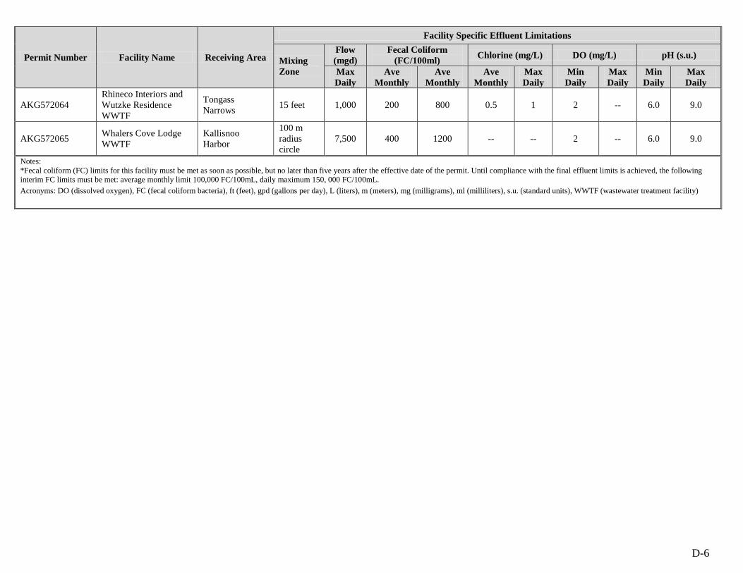
D-6
Permit Number Facility Name Receiving Area
Facility Specific Effluent Limitations
Mixing Zone
Flow (mgd)
Fecal Coliform (FC/100ml) Chlorine (mg/L) DO (mg/L) pH (s.u.)
Max Daily
Ave Monthly
Ave Monthly
Ave Monthly
Max Daily
Min Daily
Max Daily
Min Daily
Max Daily
AKG572064 Rhineco Interiors and Wutzke Residence WWTF
Tongass Narrows 15 feet 1,000 200 800 0.5 1 2 -- 6.0 9.0
AKG572065 Whalers Cove Lodge WWTF
Kallisnoo Harbor
100 m radius circle
7,500 400 1200 -- -- 2 -- 6.0 9.0
Notes: *Fecal coliform (FC) limits for this facility must be met as soon as possible, but no later than five years after the effective date of the permit. Until compliance with the final effluent limits is achieved, the following interim FC limits must be met: average monthly limit 100,000 FC/100mL, daily maximum 150, 000 FC/100mL. Acronyms: DO (dissolved oxygen), FC (fecal coliform bacteria), ft (feet), gpd (gallons per day), L (liters), m (meters), mg (milligrams), ml (milliliters), s.u. (standard units), WWTF (wastewater treatment facility)
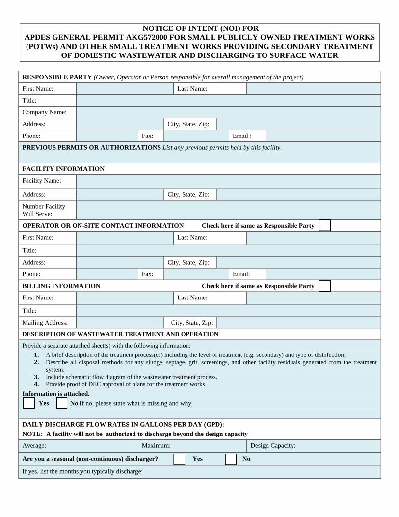
NOTICE OF INTENT (NOI) FOR APDES GENERAL PERMIT AKG572000 FOR SMALL PUBLICLY OWNED TREATMENT WORKS (POTWs) AND OTHER SMALL TREATMENT WORKS PROVIDING SECONDARY TREATMENT
OF DOMESTIC WASTEWATER AND DISCHARGING TO SURFACE WATER RESPONSIBLE PARTY (Owner, Operator or Person responsible for overall management of the project)
First Name: Last Name:
Title:
Company Name:
Address: City, State, Zip:
Phone: Fax: Email :
PREVIOUS PERMITS OR AUTHORIZATIONS List any previous permits held by this facility.
FACILITY INFORMATION
Facility Name:
Address: City, State, Zip:
Number Facility Will Serve:
OPERATOR OR ON-SITE CONTACT INFORMATION Check here if same as Responsible Party
First Name: Last Name:
Title:
Address: City, State, Zip:
Phone: Fax: Email:
BILLING INFORMATION Check here if same as Responsible Party
First Name: Last Name:
Title:
Mailing Address: City, State, Zip:
DESCRIPTION OF WASTEWATER TREATMENT AND OPERATION
Provide a separate attached sheet(s) with the following information: 1. A brief description of the treatment process(es) including the level of treatment (e.g. secondary) and type of disinfection. 2. Describe all disposal methods for any sludge, septage, grit, screenings, and other facility residuals generated from the treatment
system. 3. Include schematic flow diagram of the wastewater treatment process. 4. Provide proof of DEC approval of plans for the treatment works
Information is attached. Yes No If no, please state what is missing and why.
DAILY DISCHARGE FLOW RATES IN GALLONS PER DAY (GPD): NOTE: A facility will not be authorized to discharge beyond the design capacity
Average: Maximum: Design Capacity:
Are you a seasonal (non-continuous) discharger? Yes No
If yes, list the months you typically discharge:
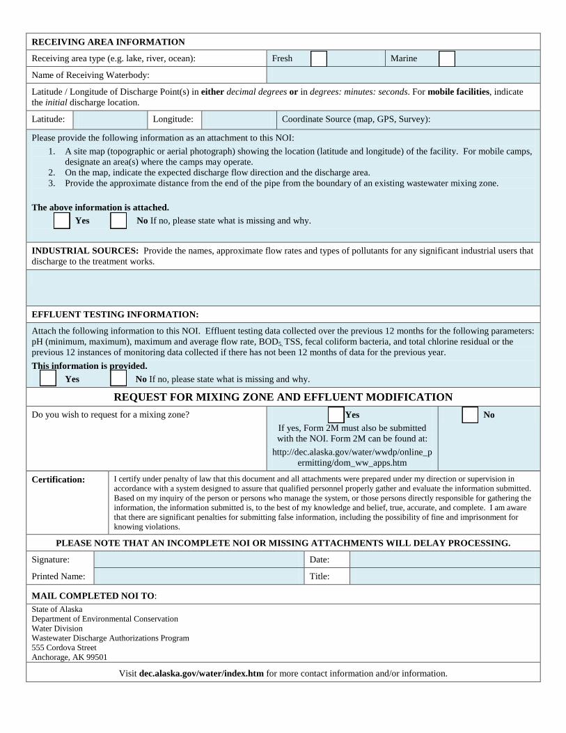
RECEIVING AREA INFORMATION
Receiving area type (e.g. lake, river, ocean): Fresh Marine
Name of Receiving Waterbody:
Latitude / Longitude of Discharge Point(s) in either decimal degrees or in degrees: minutes: seconds. For mobile facilities, indicate the initial discharge location.
Latitude: Longitude: Coordinate Source (map, GPS, Survey):
Please provide the following information as an attachment to this NOI: 1. A site map (topographic or aerial photograph) showing the location (latitude and longitude) of the facility. For mobile camps,
designate an area(s) where the camps may operate. 2. On the map, indicate the expected discharge flow direction and the discharge area. 3. Provide the approximate distance from the end of the pipe from the boundary of an existing wastewater mixing zone.
The above information is attached. Yes No If no, please state what is missing and why.
INDUSTRIAL SOURCES: Provide the names, approximate flow rates and types of pollutants for any significant industrial users that discharge to the treatment works.
EFFLUENT TESTING INFORMATION:
Attach the following information to this NOI. Effluent testing data collected over the previous 12 months for the following parameters: pH (minimum, maximum), maximum and average flow rate, BOD5, TSS, fecal coliform bacteria, and total chlorine residual or the previous 12 instances of monitoring data collected if there has not been 12 months of data for the previous year. This information is provided.
Yes No If no, please state what is missing and why.
REQUEST FOR MIXING ZONE AND EFFLUENT MODIFICATION Do you wish to request for a mixing zone? Yes
If yes, Form 2M must also be submitted with the NOI. Form 2M can be found at:
http://dec.alaska.gov/water/wwdp/online_permitting/dom_ww_apps.htm
No
Certification: I certify under penalty of law that this document and all attachments were prepared under my direction or supervision in accordance with a system designed to assure that qualified personnel properly gather and evaluate the information submitted. Based on my inquiry of the person or persons who manage the system, or those persons directly responsible for gathering the information, the information submitted is, to the best of my knowledge and belief, true, accurate, and complete. I am aware that there are significant penalties for submitting false information, including the possibility of fine and imprisonment for knowing violations.
PLEASE NOTE THAT AN INCOMPLETE NOI OR MISSING ATTACHMENTS WILL DELAY PROCESSING.
Signature: Date:
Printed Name: Title:
MAIL COMPLETED NOI TO: State of Alaska Department of Environmental Conservation Water Division Wastewater Discharge Authorizations Program 555 Cordova Street Anchorage, AK 99501
Visit dec.alaska.gov/water/index.htm for more contact information and/or information.
Page 1 of 33
Public Comment Start Date: June 5, 2012 Public Comment Expiration Date: July 5, 2012 Technical Contact: Marie Klingman Alaska Department of Environmental Conservation Division of Water Wastewater Discharge Authorization Program 610 University Avenue Fairbanks, Alaska 99709 Phone: (907) 451-2101 [email protected]
The Alaska Department of Environmental Conservation (the Department or DEC) has reissued APDES general permit to small POTWs and other small privately-owned treatment works providing secondary treatment of domestic wastewater discharging to waters of the United States (U.S.) in the State of Alaska. The general permit places conditions on the discharge of pollutants from authorized facilities to waters of the U.S. In order to ensure protection of water quality and human health, the permit places limits on the types and amounts of pollutants that can be discharged from the authorized facilities and outlines best management practices to which the facility must adhere. This fact sheet explains the nature of potential discharges from small domestic wastewater facilities and the development of the permit including:
a listing of effluent limitations, monitoring requirements and other conditions; technical material supporting the conditions in the permit; and information on appeal procedures.
ALASKA POLLUTANT DISCHARGE ELIMINATION SYSTEM (APDES) PERMIT FACT SHEET General Permit Number: AKG572000 Small Publicly Owned Treatment Works (POTWs) and other Small Treatment Works Providing Secondary Treatment of Domestic Wastewater and Discharging to Surface Water
DEPARTMENT OF ENVIRONMENTAL CONSERVATION Wastewater Discharge Authorization Program
555 Cordova Street Anchorage, AK 99501
Page 2 of 33
Appeals Process
The Department has both an informal review process and a formal administrative appeal process for final APDES permit decisions. An informal review request must be delivered within 15 days after receiving the Department’s decision to the Director, Division of Water at the following address:
Director of Water Alaska Department of Environmental Conservation 555 Cordova Street Anchorage, AK 99501
Interested persons can review 18 AAC 15.185 for the procedures and substantive requirements regarding a request for an informal Department review.
See http://www.dec.state.ak.us/commish/InformalReviews.htm for information regarding informal reviews of Department decisions.
An adjudicatory hearing request must be delivered to the Commissioner of the Department within 30 days of the permit decision or a decision issued under the informal review process. An adjudicatory hearing will be conducted by an administrative law judge in the Office of Administrative Hearings within the Department of Administration. A written request for an adjudicatory hearing shall be delivered to the Commissioner at the following address:
Commissioner Alaska Department of Environmental Conservation 410 Willoughby Street, Suite 303 Juneau, AK 99811-1800
Interested persons can review 18 AAC 15.200 for the procedures and substantive requirements regarding a request for an adjudicatory hearing. See http://www.dec.state.ak.us/commish/ReviewGuidance.htm for information regarding appeals of Department decisions.
Page 3 of 33
Documents are Available
The permit, fact sheet, application, and related documents can be obtained by visiting or contacting DEC between 8:00 a.m. and 4:30 p.m. Monday through Friday at the addresses below. The permit, fact sheet, application, and other information are also located on the Department’s Wastewater Discharge Authorization Program website: http://www.dec.state.ak.us/water/wwdp/index.htm .
Alaska Department of Environmental Conservation Division of Water Wastewater Discharge Authorization Program 555 Cordova Street Anchorage, AK 99501 (907) 269-6285
Alaska Department of Environmental Conservation Division of Water Wastewater Discharge Authorization Program 610 University Avenue Fairbanks, AK 99709 (907) 451-2183
Alaska Department of Environmental Conservation Division of Water Wastewater Discharge Authorization Program 410 Willoughby Avenue, Suite 310 Juneau, AK 99801 (907) 465-5180
Page 4 of 33
TABLE OF CONTENTS
1.0 INTRODUCTION .............................................................................................................. 6
1.1 BASIS FOR ISSUANCE OF A GENERAL PERMIT .................................................... 6 1.2 PERMIT ISSUANCE HISTORY ...................................................................................... 6 1.3 DESCRIPTION OF WWTF OPERATIONS ................................................................... 7
2.0 PERMIT COVERAGE ...................................................................................................... 8
2.1 FACILITIES AND DISCHARGES COVERED BY THE PERMIT ............................ 8 2.2 AUTOMATIC COVERAGE ............................................................................................. 8 2.3 APPLYING FOR COVERAGE ........................................................................................ 9
3.0 EFFLUENT LIMITS ......................................................................................................... 9
3.1 BASIS FOR PERMIT LIMITS ......................................................................................... 9 3.2 TECHNOLOGY-BASED EFFLUENT LIMITS ............................................................. 9 3.3 WATER QUALITY-BASED EFFLUENT LIMITS ..................................................... 11 3.4 FLOW ................................................................................................................................ 14 3.5 MASS-BASED LIMITS ................................................................................................... 14 3.6 EFFLUENT LIMITS SUMMARY ................................................................................. 14
4.0 MIXING ZONES .............................................................................................................. 15
5.0 MONITORING ................................................................................................................ 16
5.1 BASIS FOR EFFLUENT AND AMBIENT MONITORING ....................................... 16 5.2 ENTEROCOCCI BACTERIA ........................................................................................ 16 5.3 TOTAL AMMONIA AS NITROGEN ............................................................................ 17 5.4 TEMPERATURE AND PH ............................................................................................. 17 5.5 MONITORING FREQUENCIES ................................................................................... 17
6.0 AMBIENT MONITORING ............................................................................................ 20
7.0 COMPLIANCE SCHEDULES ....................................................................................... 20
8.0 ANTI-BACKSLIDING .................................................................................................... 20
9.0 ANTIDEGRADATION.................................................................................................... 21
10.0 OTHER LEGAL REQUIREMENTS ............................................................................. 25
10.1 ENDANGERED SPECIES ACT ..................................................................................... 25 10.2 ESSENTIAL FISH HABITAT ........................................................................................ 27 10.3 OCEAN DISCHARGE CRITERIA EVALUATION .................................................... 28 10.4 PERMIT EXPIRATION .................................................................................................. 28
Page 5 of 33
TABLES Table 1: Technology-Based Effluent Limits ................................................................................. 11 Table 2: Water Quality Based Effluent Limits ............................................................................. 13 Table 3: Effluent Limits ................................................................................................................ 15 Table 4: Monitoring Requirements ............................................................................................... 19 Table 5: Threatened and Endangered Species .............................................................................. 26 Appendix A. Mixing Zone Analysis Check List
Page 6 of 33
1.0 INTRODUCTION
1.1 Basis for Issuance of a General Permit Section 301(a) of the Clean Water Act (CWA) and 18 AAC 83.015 provided that the discharge of pollutants is unlawful except in accordance with an APDES permit. Although such permits are usually issued to individual dischargers, DEC regulations at 18 AAC 83.205 authorize Departmental issuance of general permits to categories or subcategories of discharges within existing geographic or political boundaries when
1.1.1 a number of point sources involve the same or substantially similar types of operations;
1.1.2 discharge the same types of wastes;
1.1.3 require the same effluent limits or operating conditions;
1.1.4 require the same or similar monitoring requirements; and
1.1.5 in the opinion of the Department, are more appropriately controlled under a general permit than under individual permits.
A violation of a condition contained in a general permit constitutes a violation of the CWA and subjects the owner or operator of the permitted discharge to the penalties specified in Section 309 of the CWA.
1.2 Permit Issuance History In 2004, the Environmental Protection Agency (EPA) identified approximately 100 small publicly owned treatment works (POTWs) and privately-owned treatment works in Alaska as candidates for general permit coverage. These were smaller facilities discharging less than 1.0 million gallons per day (mgd) treating predominately domestic wastewater and discharging to waters of the U.S. in the State of Alaska. The types of operations at these facilities, the waste, operating conditions, effluent limits, and monitoring requirements were all similar in this group. Therefore, EPA determined that a general permit was an appropriate National Pollutant Discharge Elimination System permit mechanism for these dischargers. Upon further evaluation by EPA, it was concluded that two general permits were necessary to address the low-volume domestic discharges in the State, one for facilities that discharged to freshwater (AKG570000) and one for facilities that discharged to marine water (AKG571000). Because Alaska Water Quality Standards (WQS) contain permit limitations that are different for freshwater and marine dischargers, EPA opted for two general permits in order to clarify the requirements. Both general permits were assigned effective dates of July 21, 2004 and corresponding expiration date of July 21, 2009. In accordance with 18 AAC 83.155, facilities authorized to discharge domestic wastewater under these permits have been operating
Page 7 of 33
under an administrative extension since the permits’ expiration (i.e. the conditions of the prior permits remain in effect and enforceable until a new permit is issued by the Department). The Department is now reissuing AKG570000 and AKG571000 under general permit number AKG572000. This reissued general permit only authorizes discharges from facilities that use a mechanical means to treat domestic wastewater and that discharge to surface water. AKG572000 specifically re-authorizes existing discharges and authorizes new discharges from publicly and privately owned domestic wastewater treatment facilities (WWTFs) in the State of Alaska. Facilities previously authorized to discharge under either AKG570000 or AKG571000 that do not qualify for coverage under AKG572000 (i.e. lagoons, common collectors, etc.) will be administratively extended under the expired general permits until the Department provides coverage for them under a new general permit in the near future. Types of facilities and discharges not covered by AKG572000 are listed in part 1.3 of the permit. There are approximately 50 facilities that were authorized to discharge to freshwater under AKG57000 or marine water under AKG571000 that are eligible for coverage under the reissued general permit. The facilities previously covered under general permits AKG570000 and AKG571000, as well as those facilities that the Department determines to be qualified for coverage under the reissued permit, will be granted automatic coverage under AKG572000. These facilities are listed in Appendix D of the general permit.
1.3 Description of WWTF Operations The operations at WWTFs that will be covered under the general permit generally include preliminary processes (e.g. pumping, screening, and grit removal), primary settling treatment in large primary clarifiers or sedimentation tanks to remove settleable suspended solids, and biological secondary treatment processes. The secondary treatment step is often achieved by an activated sludge system in which wastewater is continuously fed into an aerated tank where it is mixed with an active mass of microorganisms (i.e. activated sludge) capable of aerobically degrading organic matter. After a specific treatment time, the mixed liquor passes into a secondary clarifier where the sludge settles under quiescent conditions and a clarified effluent is produced for discharge. Most facilities provide some level of disinfection either via chlorination or ultra-violet radiation prior to discharge as well. Advanced technologies used increasingly in Alaska include membrane bioreactors (MBRs). MBRs combine the use of biological processes and membrane technology to provide a high standard of wastewater treatment. Instead of the secondary clarifier used in the activated sludge process, flow in the MBR system passes through a microporous membrane while solids and large bacteria remain in the treatment system for biological degradation. MBRs can operate at longer solids detention times, thereby not only enhancing the treatment of organic matter, but producing less waste biosolids (or sludge).
Page 8 of 33
The waste biosolids generated by the treatment processes is generally thickened and processed for ultimate disposal. Dewatered biosolids in Alaska are generally either co-incinerated, placed in the municipal solid waste landfill, or land applied. However, biosolids handling and disposal are regulated under separate federal regulations and therefore are not addressed by the general permit.
2.0 PERMIT COVERAGE
2.1 Facilities and Discharges Covered by the Permit Coverage under the general permit will be limited to WWTFs that treat primarily domestic wastewater to secondary treatment standards, have an actual flow and design flow of less than 1.0 mgd, and that discharge to surface water. The WWTFs pre-selected for coverage under the general permit use processes similar to the description of operations described in fact sheet section 1.3. These facilities are listed in two tables of Appendix D of the permit. Appendix D, Table A contains a list of WWTFs that were authorized to discharge under the administratively extended AKG570000 and AKG5710000 general permits, and Appendix D, Table B contains a list of WWTFs that submitted a notice of intent (NOI) requesting permit coverage after the expiration date of the 2004 EPA-issued general permits as well as WWTFs that were previously covered under state permits. See part 1.3 of the general permit for facilities and discharges that are not covered by the permit.
2.2 Automatic Coverage 18 AAC 83.210(h) provides that the Department may notify a discharger that their discharge is covered by a general permit even if the discharger has not submitted a NOI seeking coverage. A discharger so notified may request an individual permit under 18 AAC 83.215(b). WWTFs authorized under the administratively extended AKG570000 and AKG571000 EPA-issued general permits with the exception of those facilities that are excluded under part 1.3 of the permit, will receive automatic coverage. Upon permit coverage, an authorization letter identifying a new APDES authorization number and a copy of the final general permit and fact sheet will be sent to qualified facilities. Authorization to discharge under the general permit does not begin until the permittee receives a written notice of authorization from the Department. As previously mentioned, 18 AAC 83.215(b) allows any owner or operator authorized by a general permit to request to be excluded from the coverage of the general permit by applying for an individual permit. The responsible party shall submit an individual permit application (Form 2A and Form 2M if requesting a mixing zone) with reasons supporting the request to the Department no later than 90 days after the publication of the general permit. The request shall be processed under the provisions of 18 AAC
Page 9 of 33
83.115 and 18 AAC 83.120. The Department will grant the request by issuing an individual permit if the reasons cited by the responsible party are adequate to support the request. A permittee who already has authorization to discharge under an individual permit may request general permit coverage. If the Department approves coverage under a general permit, the individual permit is revoked.
2.3 Applying for Coverage The Department anticipates that there are additional facilities that could obtain coverage under the general permit. These include facilities that are currently operating as well as new facilities. The procedure for obtaining authorization to discharge under the general permit is as follows:
a) The eligible facility submits a completed NOI to the Department at least 30 days before the expected start of discharge. See part 1.4 of the general permit for specific notification requirements.
b) The Department reviews the NOI for completeness.
c) If the NOI is considered complete and the facility is considered eligible for coverage under the general permit, the Department sends the permittee a written notice of authorization. Authorization to discharge under the general permit does not begin until the permittee receives a written notice of authorization from the Department. If the Department determines that the NOI is not complete, the Department will request that additional information be submitted. If the Department determines that the facility is not eligible for coverage under the general permit, authorization will be denied and, if appropriate, the applicant will be directed to submit an application for an individual permit.
3.0 EFFLUENT LIMITS
3.1 Basis for Permit Limits
In general, the CWA requires that the limits for a particular pollutant be the more stringent of either technology-based effluent limits (TBELs) or water quality-based effluent limits (WQBELs). TBELs are set according to the level of treatment that is achievable using available technology. A WQBEL is designed to ensure that the WQS of a waterbody are met and may be more stringent than TBELs. A discussion of the basis for the effluent limits contained in AKG572000 follows.
3.2 Technology-Based Effluent Limits
5-Day Biochemical Oxygen Demand (BOD5), Total Suspended Solids (TSS), pH, and Total Residual Chlorine (TRC)
The CWA requires a POTW to meet requirements based on available wastewater treatment technology. Section 301 of the CWA established a required technology-based
Page 10 of 33
performance level, referred to as “secondary treatment,” that all POTWs were required to meet by July 1, 1977. “Secondary treatment” TBELs are established in 40 Code of Federal Regulations (CFR) §133.102 [which are adopted by reference at 18 AAC 83.010(e)]. The TBELs apply to all POTWs and identify the minimum level of effluent quality attainable by application of secondary treatment in terms of the pollutants BOD5, TSS, and pH. Per 40 CFR §125.3(c)(2), the Department is also using best professional judgment under section 402(a)(1) of the CWA to implement case-by-case technology-based secondary treatment requirements for non-POTWs (i.e. privately-owned treatment facilities) authorized to discharge domestic wastewater under this general permit. The secondary treatment requirements found in 40 CFR §133.102 were promulgated specifically for POTWs. While secondary requirements only directly apply to POTWs, the Department is applying secondary treatment standards to the privately-owned treatment facilities covered by this permit as they are identical to POTWs in mechanics and treatment efficacy, and accordingly, (the secondary standards) provide the most meaningful baseline pollutant control guidelines for this sector of privately-owned treatment facilities. Monthly, weekly, and percent removal BOD5 and TSS effluent requirements as well as pH minimum and maximum effluent limits may be found in the federal secondary treatment regulations at 40 CFR Part 133. Additionally, a maximum daily limit (MDL) of 60 milligrams per liter (mg/L) for BOD5 and TSS is included in the general permit (as was required in the previous general permits) to meet the conditions of 18 AAC 83.480 (reissued permits) that require effluent limits, standards, or conditions to be at least as stringent as the final effluent limits, standards, or conditions in the previous permit. The TRC limit of 0.5 mg/L is not found at 40 CFR §133.102 [adopted by reference at 18 AAC 83.010(e)] nor is it a state regulation; rather it is derived from standard domestic wastewater treatment operating practices. The Water Pollution Control Federation's (WPCF) Chlorination of Wastewater (1976), indicates that a properly designed and maintained wastewater treatment plant can achieve adequate disinfection if a 0.5 mg/L chlorine residual concentration is maintained after 15 minutes of contact time. The WPCF concluded that a treatment plant that provides adequate chlorination contact time can meet the 0.5 mg/L limit on a monthly average basis. An average monthly limit (AML) of 0.5 mg/L for TRC was applied as a TBEL in the previous general permits for facilities with authorized TRC mixing zones. (see fact sheet section 4.0 for a discussion on mixing zones). The general permits also contained a TRC MDL of 1.0 mg/L. Consistent with the conditions of 18 AAC 83.480 (reissued permits) that require effluent limits, standards, or conditions to be at least as stringent as the final effluent limits, standards, or conditions in the previous permit, and in the absence of new information to indicate TRC technological advances that would alter the WPCF’s 1976 conclusions, the TRC limits that were applied as TBELs in the previous general permits are being applied as TRC TBELs in AKG572000.
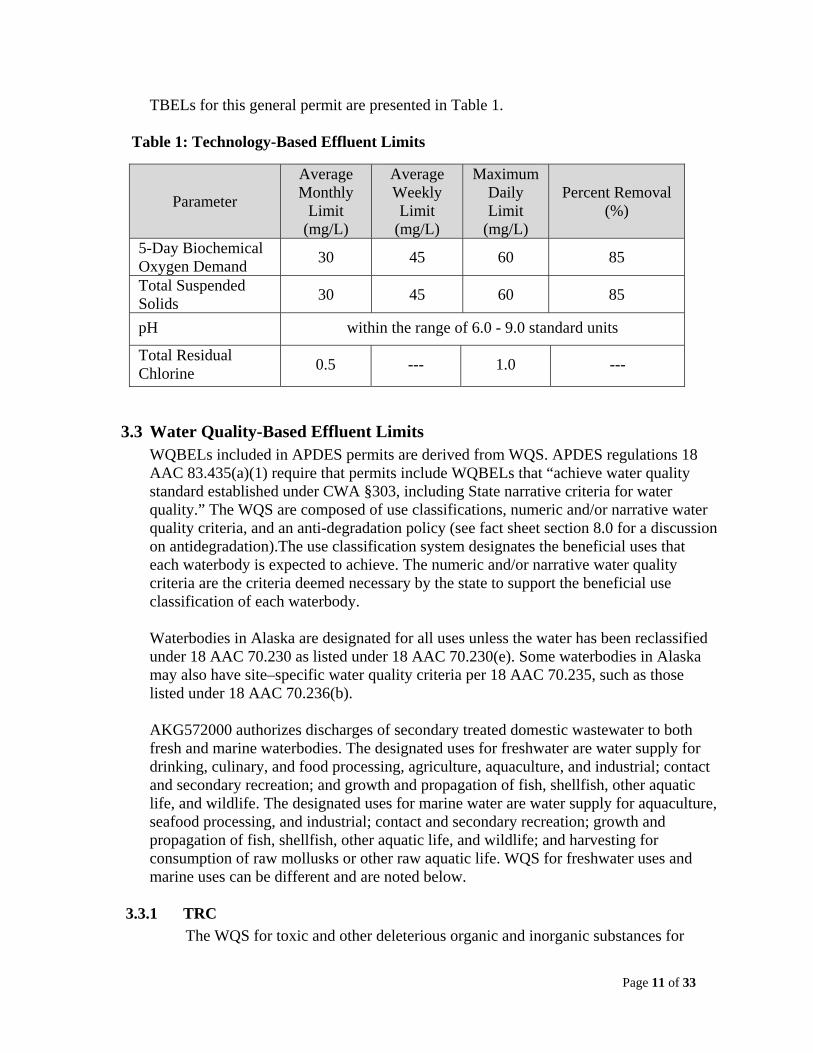
Page 11 of 33
TBELs for this general permit are presented in Table 1.
Table 1: Technology-Based Effluent Limits
Parameter
Average Monthly
Limit (mg/L)
Average Weekly Limit
(mg/L)
Maximum Daily Limit
(mg/L)
Percent Removal (%)
5-Day Biochemical Oxygen Demand
30 45 60 85
Total Suspended Solids
30 45 60 85
pH within the range of 6.0 - 9.0 standard units
Total Residual Chlorine
0.5 --- 1.0 ---
3.3 Water Quality-Based Effluent Limits WQBELs included in APDES permits are derived from WQS. APDES regulations 18 AAC 83.435(a)(1) require that permits include WQBELs that “achieve water quality standard established under CWA §303, including State narrative criteria for water quality.” The WQS are composed of use classifications, numeric and/or narrative water quality criteria, and an anti-degradation policy (see fact sheet section 8.0 for a discussion on antidegradation).The use classification system designates the beneficial uses that each waterbody is expected to achieve. The numeric and/or narrative water quality criteria are the criteria deemed necessary by the state to support the beneficial use classification of each waterbody. Waterbodies in Alaska are designated for all uses unless the water has been reclassified under 18 AAC 70.230 as listed under 18 AAC 70.230(e). Some waterbodies in Alaska may also have site–specific water quality criteria per 18 AAC 70.235, such as those listed under 18 AAC 70.236(b). AKG572000 authorizes discharges of secondary treated domestic wastewater to both fresh and marine waterbodies. The designated uses for freshwater are water supply for drinking, culinary, and food processing, agriculture, aquaculture, and industrial; contact and secondary recreation; and growth and propagation of fish, shellfish, other aquatic life, and wildlife. The designated uses for marine water are water supply for aquaculture, seafood processing, and industrial; contact and secondary recreation; growth and propagation of fish, shellfish, other aquatic life, and wildlife; and harvesting for consumption of raw mollusks or other raw aquatic life. WQS for freshwater uses and marine uses can be different and are noted below.
3.3.1 TRC
The WQS for toxic and other deleterious organic and inorganic substances for
Page 12 of 33
freshwater uses are codified in 18 AAC 70.020(b)(11) and for marine water uses in 18 AAC 70.020(b)(23). TRC criteria provide protection for aquatic life. For freshwater the WQS requires that TRC may not exceed either an acute concentration of 0.019 mg/L or a chronic concentration of 0.011 mg/L. For marine water the WQS requires that TRC may not exceed either an acute concentration of 0.013 mg/L or a chronic concentration of 0.0075 mg/L.
3.3.2 Fecal Coliform Bacteria (FC)
FC bacteria are a non-pathogenic indicator species whose presence suggests the likelihood that pathogenic bacteria are present. The most stringent WQS at 18 AAC 70.020(b)(2)(A) provides protection for freshwater designated for drinking, culinary, and food processing water supply. The WQS requires that in a 30-day period, the geometric mean may not exceed 20 FC/100 mL, and not more than 10% of the samples may exceed 40 FC/100 mL. The most stringent WQS at 18 AAC 70.020(b)(14)(D) provides protection for marine water designated for harvesting for consumption of raw mollusks or other raw aquatic life. The WQS require that in a 30-day period, the geometric mean of samples may not exceed 14 FC/100 mL, and not more than 10 percent of the total samples may exceed 43 FC/100 mL.
3.3.3 Dissolved Oxygen (DO)
WQS at 18 AAC 70.020(b)(3) states that surface DO for freshwater uses to include the growth and propagation of fish, shellfish, other aquatic life, and wildlife must be greater than 7 mg/L and in no case may DO be greater than 17 mg/L. WQS at 18 AAC 70.020(b)(15)(C) states that surface DO for marine water uses to include the growth and propagation of fish, shellfish, other aquatic life, and wildlife must be greater than 6 mg/L and that in no case may DO be greater than 17 mg/L.
3.3.4 pH
WQS for pH at 18 AAC 70.020(b)(6) for freshwater uses and 18 AAC 70.020(b)(18)(C) for marine uses provides protection for the growth and propagation of fish, shellfish, other aquatic life, and wildlife. The WQS for both freshwater and marine water ph may not be less than 6.5 standard pH units (s.u.) or greater than 8.5 s.u. Table 2 lists the applicable water criteria as WQBELs for TRC, FC, DO and pH.
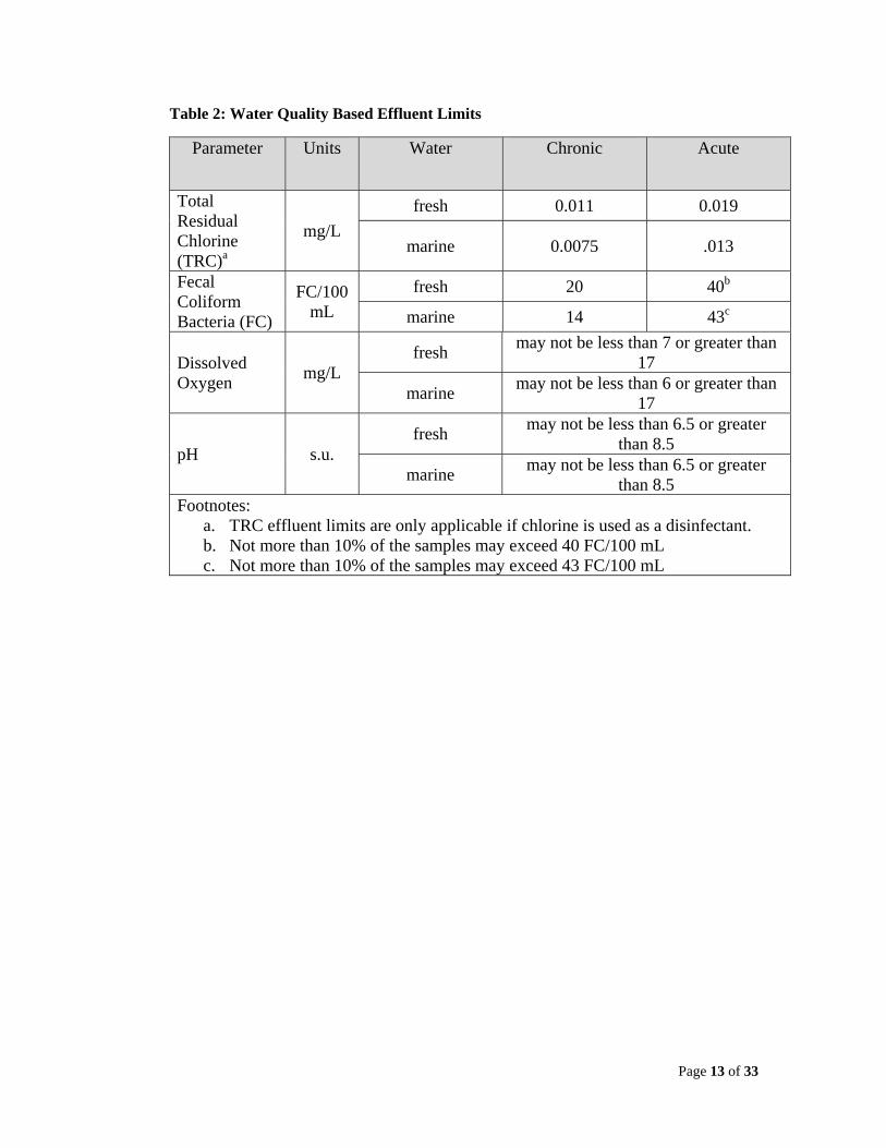
Page 13 of 33
Table 2: Water Quality Based Effluent Limits
Parameter Units Water Chronic Acute
Total Residual Chlorine (TRC)a
mg/L
fresh 0.011 0.019
marine 0.0075 .013
Fecal Coliform Bacteria (FC)
FC/100 mL
fresh 20 40b
marine 14 43c
Dissolved Oxygen
mg/L fresh
may not be less than 7 or greater than 17
marine may not be less than 6 or greater than
17
pH s.u. fresh
may not be less than 6.5 or greater than 8.5
marine may not be less than 6.5 or greater
than 8.5 Footnotes:
a. TRC effluent limits are only applicable if chlorine is used as a disinfectant. b. Not more than 10% of the samples may exceed 40 FC/100 mL c. Not more than 10% of the samples may exceed 43 FC/100 mL
Page 14 of 33
3.4 Flow Flow will be based on the hydraulic design capacity of the WWTF (flow rate as gallons per day) and shall be determined by a professional engineer and approved by the Department during the WWTF plan review process conducted per 18 AAC 72. A flow limit based on the design capacity ensures that the WWTF operates within its capabilities to receive and properly treat sustained average flow quantities and specific pollutants.
3.5 Mass-Based Limits The general permit contains place holders for mass-based limits for BOD5 and TSS. State regulations at 18 AAC 83.540 require that effluent limits be expressed in terms of mass unless they cannot appropriately be expressed by mass, if it is infeasible, or if the limits can be expressed in terms of other units of measurement. In addition, 18 AAC 83.520 requires that effluent limits for a POTW be calculated based on the design flow of the WWTF. Expressing limitations in terms of concentration as well as mass encourages the proper operation of a WWTF at all times.
Because mass-based limits are derived from the facility’s design flow, they must be calculated for each facility and therefore mass-based limits will be assigned during the authorization process. The mass-based limits are expressed in lbs/day and are calculated as follows:
8.34
3.6 Effluent Limits Summary The more stringent of the technology or WQBELs are included as permit limits.
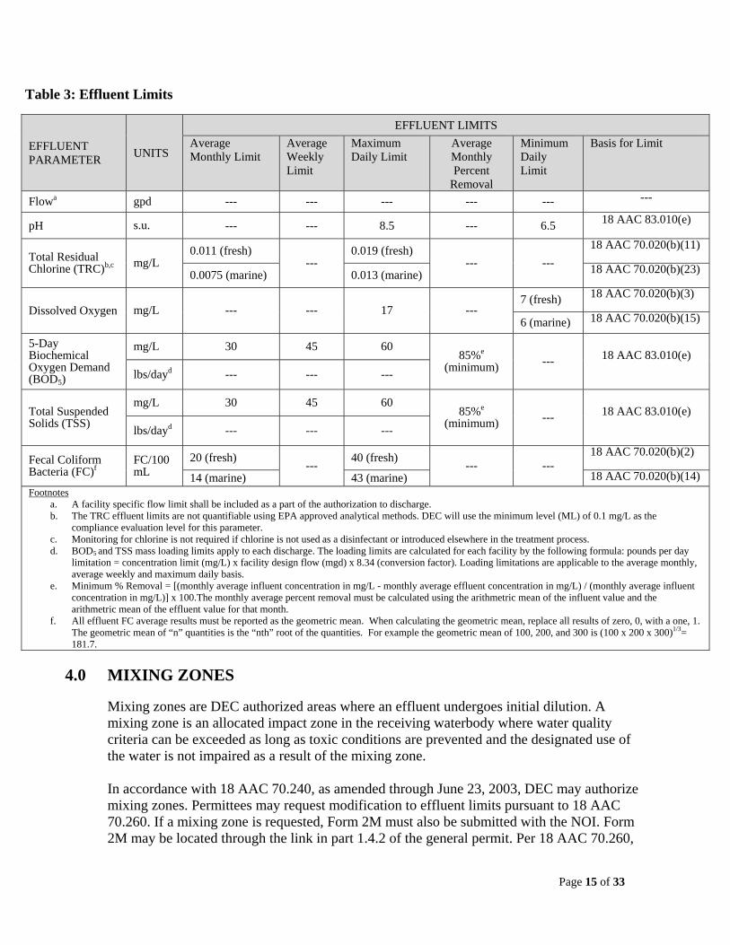
Page 15 of 33
Table 3: Effluent Limits
EFFLUENT PARAMETER
UNITS
EFFLUENT LIMITS
Average Monthly Limit
Average Weekly Limit
Maximum Daily Limit
Average Monthly Percent
Removal
Minimum Daily Limit
Basis for Limit
Flowa gpd --- --- --- --- --- ---
pH s.u. --- --- 8.5 --- 6.5 18 AAC 83.010(e)
Total Residual Chlorine (TRC)b,c mg/L
0.011 (fresh) ---
0.019 (fresh) --- ---
18 AAC 70.020(b)(11)
0.0075 (marine) 0.013 (marine) 18 AAC 70.020(b)(23)
Dissolved Oxygen mg/L --- --- 17 --- 7 (fresh) 18 AAC 70.020(b)(3)
6 (marine) 18 AAC 70.020(b)(15)
5-Day Biochemical Oxygen Demand (BOD5)
mg/L 30 45 60 85%e
(minimum) --- 18 AAC 83.010(e)
lbs/dayd --- --- ---
Total Suspended Solids (TSS)
mg/L 30 45 60 85%e
(minimum) --- 18 AAC 83.010(e)
lbs/dayd --- --- ---
Fecal Coliform Bacteria (FC)f
FC/100 mL
20 (fresh) ---
40 (fresh) --- ---
18 AAC 70.020(b)(2)
14 (marine) 43 (marine) 18 AAC 70.020(b)(14)Footnotes
a. A facility specific flow limit shall be included as a part of the authorization to discharge. b. The TRC effluent limits are not quantifiable using EPA approved analytical methods. DEC will use the minimum level (ML) of 0.1 mg/L as the
compliance evaluation level for this parameter. c. Monitoring for chlorine is not required if chlorine is not used as a disinfectant or introduced elsewhere in the treatment process. d. BOD5 and TSS mass loading limits apply to each discharge. The loading limits are calculated for each facility by the following formula: pounds per day
limitation = concentration limit (mg/L) x facility design flow (mgd) x 8.34 (conversion factor). Loading limitations are applicable to the average monthly, average weekly and maximum daily basis.
e. Minimum % Removal = [(monthly average influent concentration in mg/L - monthly average effluent concentration in mg/L) / (monthly average influent concentration in mg/L)] x 100.The monthly average percent removal must be calculated using the arithmetric mean of the influent value and the arithmetric mean of the effluent value for that month.
f. All effluent FC average results must be reported as the geometric mean. When calculating the geometric mean, replace all results of zero, 0, with a one, 1. The geometric mean of “n” quantities is the “nth” root of the quantities. For example the geometric mean of 100, 200, and 300 is (100 x 200 x 300)1/3= 181.7.
4.0 MIXING ZONES
Mixing zones are DEC authorized areas where an effluent undergoes initial dilution. A mixing zone is an allocated impact zone in the receiving waterbody where water quality criteria can be exceeded as long as toxic conditions are prevented and the designated use of the water is not impaired as a result of the mixing zone. In accordance with 18 AAC 70.240, as amended through June 23, 2003, DEC may authorize mixing zones. Permittees may request modification to effluent limits pursuant to 18 AAC 70.260. If a mixing zone is requested, Form 2M must also be submitted with the NOI. Form 2M may be located through the link in part 1.4.2 of the general permit. Per 18 AAC 70.260,
Page 16 of 33
the burden of proof for justifying a mixing zone rests with the applicant. Note the Department has determined that existing dischargers listed in Appendix D of the permit (that requested a mixing zone) have satisfied this requirement. Appendix A outlines criteria that must be met prior to the Department authorizing a mixing zone. These criteria include an analysis of the size of the mixing zone, treatment technology, existing uses of the waterbody, human consumption, spawning areas, human health, aquatic life, and endangered species. If one criterion is not met, then a mixing zone is prohibited and effluent limits must be met at the end of the outfall line prior to discharge to the receiving waterbody. The Department may establish limits at the boundary of an authorized mixing zone in the receiving waterbody. These limits shall be based on the limits and requirements of the Alaska WQS (18 AAC 70). The permittee will be notified of any receiving waterbody limits when issued authorization by DEC to discharge under the general permit. The Department reviewed effluent and mixing zone monitoring data for each of the facilities that were authorized mixing zones under AKG570000 and AKG571000. The monitoring results do not support revising the mixing zones, nor is there a documented basis for concern to do so at this time. Therefore, the mixing zones for each of the facilities previously authorized under AKG570000 and AKG571000 and that are eligible for coverage under AKG572000 shall be reauthorized. If facility conditions change (e.g. increase flow volume) requiring the permittee to provide updated mixing information, DEC will evaluate the submitted information to determine if modification of the existing mixing zone authorization is warranted.
5.0 MONITORING
5.1 Basis for Effluent and Ambient Monitoring In accordance with 18 AAC 83.430, the Department may specify in a permit the terms and conditions under which waste material may be disposed of. Monitoring in permits is required to determine compliance with effluent limits. Monitoring may also be required to gather effluent and surface water data to determine if additional effluent limits are required and/or to monitor effluent impact on receiving waterbody quality. The permittees are responsible for conducting the monitoring and for reporting results on DMRs or on the application for renewal, as appropriate, to the Department. In addition to the pollutants that are listed above as having permit limits that require monitoring to track compliance, sections 5.2 through 5.4 outline additional monitoring requirements DEC has determined necessary to implement in the permit.
5.2 Enterococci Bacteria Enterococci bacteria are indicator organisms of harmful pathogens in marine water and are a better indicator of acute gastrointestinal illness than fecal coliform bacteria. In 1986 EPA published Ambient Water Quality Criteria for Bacteria-1986 that contained their recommended bacteria water quality criteria for primary contact recreational users from gastrointestinal illness. The Beaches Environmental Assessment and Coastal
Page 17 of 33
Health Act of 2000 requires states and territories with coastal recreation waters to adopt bacteria criteria into their WQS that are as protective as EPA’s 1986 published bacteria criteria by April 10, 2004. Alaska did not adopt the enterococci bacteria into the WQS by the April 10, 2004 deadline, therefore EPA promulgated the 1986 bacteria criteria for Alaskan coastal recreational waters in 2004. Accordingly, monitoring for enterococci bacteria shall be required for all facilities authorized to discharge under AKG572000. At the end of the five year permit cycle, DEC will evaluate the monitoring data and assess the need for applying enterococci limits in the next reissuance of the general permit.
5.3 Total Ammonia as Nitrogen Total ammonia is the sum of ionized (NH4
+) and un-ionized ammonia (NH3). Temperature and pH affect which form, NH4
+ or NH3 is present. NH3, which is more toxic to aquatic organisms than NH4
+, predominates at higher pH and temperature levels.
Biological wastewater treatment processes reduce the amount of total nitrogen in domestic wastewater; however without advanced treatment, wastewater effluent may still contain elevated levels of ammonia nitrogen. Excess ammonia nitrogen in the environment can lead to dissolved oxygen depletion, eutrophication, and toxicity to aquatic organisms.
In order to evaluate the discharge of ammonia nitrogen, the Department is requiring that the largest facilities, those that discharge above 0.25 mgd up to 1.0 mgd and that would likely have the largest impact in the environment, to monitor for total ammonia as nitrogen for four years beginning in the second year of the general permit. Criteria for ammonia are pH and temperature dependent; therefore temperature and pH measurements shall be taken concurrently with ammonia. The Department will analyze the monitoring results to determine whether continued monitoring or limits for total ammonia are warranted in the next reissuance of the general permit. If the Department discontinues ammonia monitoring it will be discontinued as per the requirements for reissued permits at 18 AAC 83.480.
5.4 Temperature and pH
Criteria for ammonia are pH and temperature dependent, therefore temperature and the pH measurements that are necessary for ammonia monitoring shall be taken concurrently with ammonia.
5.5 Monitoring Frequencies Monitoring frequencies are based on the nature and effect of the pollutant, as well as a determination of the minimum sampling necessary to adequately monitor the facility’s performance and compliance. Permittees have the option of taking more frequent samples than are required under the general permit. These samples must be used for averaging if they are conducted using the Department-approved test methods (generally found in 18 AAC 70 and 40 CFR §136 [adopted by reference in 18 AAC 83.010]) and if the method detection limits are less than the effluent limits. Facilities covered under the general permit are expected to range in size from a few hundred gallons per day (gpd) discharge up to 1 mgd. Given this wide range in discharge

Page 18 of 33
volume, the general permit requires monitoring frequencies that are dependent on the design flow of the facility. The monitoring frequencies are divided into three categories:
Class A WWTFs with a design flow above 250,000 gpd up to 1.0 mgd Class B WWTFs with a design flow above 5,000 gpd up to and including
250,000 gpd Class C WWTFs with a design flow less than and including 5,000 gpd
Table 4 summarizes monitoring frequencies for the three design flow categories.
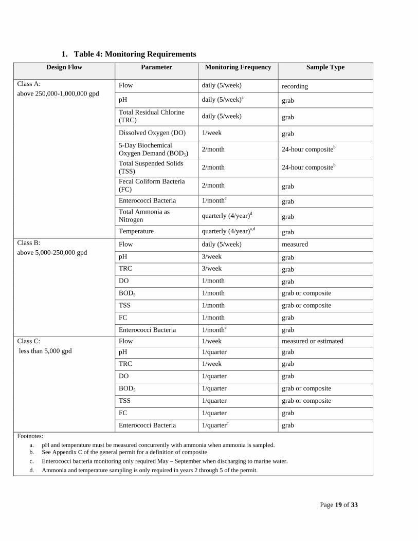
Page 19 of 33
1. Table 4: Monitoring Requirements
Design Flow Parameter Monitoring Frequency Sample Type
Class A:
above 250,000-1,000,000 gpd Flow daily (5/week) recording
pH daily (5/week)a grab
Total Residual Chlorine (TRC) daily (5/week) grab
Dissolved Oxygen (DO) 1/week grab
5-Day Biochemical Oxygen Demand (BOD5)
2/month 24-hour compositeb
Total Suspended Solids (TSS)
2/month 24-hour compositeb
Fecal Coliform Bacteria (FC)
2/month grab
Enterococci Bacteria 1/monthc grab
Total Ammonia as Nitrogen
quarterly (4/year)d grab
Temperature quarterly (4/year)a,d grab
Class B:
above 5,000-250,000 gpd Flow daily (5/week) measured
pH 3/week grab
TRC 3/week grab
DO 1/month grab
BOD5 1/month grab or composite
TSS 1/month grab or composite
FC 1/month grab
Enterococci Bacteria 1/monthc grab
Class C:
less than 5,000 gpd
Flow 1/week measured or estimated
pH 1/quarter grab
TRC 1/week grab
DO 1/quarter grab
BOD5 1/quarter grab or composite
TSS 1/quarter grab or composite
FC 1/quarter grab
Enterococci Bacteria 1/quarterc grab
Footnotes:
a. pH and temperature must be measured concurrently with ammonia when ammonia is sampled. b. See Appendix C of the general permit for a definition of composite
c. Enterococci bacteria monitoring only required May – September when discharging to marine water.
d. Ammonia and temperature sampling is only required in years 2 through 5 of the permit.
Page 20 of 33
6.0 AMBIENT MONITORING
Receiving water monitoring is occasionally required in APDES permits in order to evaluate if the effluent is causing or contributing to an in stream excursion of WQS. Given the nature and size of the discharges authorized under the general permit, ambient monitoring is not a permit requirement. The permit, however, does allow the permitting authority to require ambient monitoring under specific situations. Ambient monitoring may be required in individual authorizations for site specific evaluations related to: protection of WQS, evaluation of receiving waterbody impairments, or, evaluation or issues associated with threatened or endangered species. The permittee will be notified of any additional monitoring when issued authorization to discharge under the general permit.
7.0 COMPLIANCE SCHEDULES
Per 18 AAC 70.910, the Department has authority to include compliance schedules as conditions of a permit, certification, or approval. 18 AAC 83.560 also specifically discusses compliance schedules in APDES permits. DEC has determined that facilities that have historically received authorizations containing high FC permit effluent limits (e.g. AML 100,000 FC/100 mL, MDL 150,000 FC/100 mL) will receive five-year compliance schedules in their authorizations to come into compliance with the more stringent FC limits (AML 200 FC/100 mL, AWL 400 FC/100 mL, MDL 800 FC/100 mL) that the vast majority of permittees covered by this general permit have demonstrated the capability of achieving on a regular basis. Compliance with the new FC effluent limits must be met as soon as possible. However, in order to meet the new FC effluent limits, facility upgrades may become necessary and will require the submittal and DEC approval of engineered plans, the procurement of funding, the seeking and awarding of bids, the construction or installation of new treatment operations, the receipt of DEC’s final approval to operate, and the optimization of the facility with the new upgrade. Therefore, a five-year compliance schedule will provide a reasonable and appropriate time frame to achieve compliance with the new FC effluent limits. Also since the compliance schedules will extend beyond one year, 18 AAC 83.560(b) states that interim requirements and dates for their achievement must be established. These interim requirements and dates for their achievement will be outlined in each authorization that obtains the five-year compliance schedule.
8.0 ANTI-BACKSLIDING
18 AAC 83.480 requires that “effluent limitations, standards, or conditions must be at least as stringent as the final effluent limitations, standards, or conditions in the previous permit.” 18 AAC 83.480 (c) also says that a permit may not be reissued “to contain an effluent limitation that is less stringent than required by effluent guidelines in effect at the time the permit is renewed or reissued.” The effluent limitations in this permit reissuance are consistent with 18 AAC 83.430. The permit effluent limitations, standards, and conditions in AKG572000 are
Page 21 of 33
as stringent as in the previous permits, AKG570000 and AKG571000. Accordingly, no backsliding analysis is required for this permit reissuance.
9.0 ANTIDEGRADATION
The Antidegradation Policy of the Alaska WQS (18 AAC 70.015) states that the existing water uses and the level of water quality necessary to protect existing uses must be maintained and protected. The Department’s approach to implementing the policy found in 18 AAC 70.015 is based on the requirements in 18 AAC 70 and the Interim Antidegradation Implementation Methods dated July 14, 2010. Using these requirements and policies, the Department determines on a parameter-by-parameter basis whether a waterbody or a portion of a waterbody is classified tier 1, 2, or 3 where a larger number indicates a greater level of water quality protection. Tier 3 classifications, or “outstanding national resource” waters, have not currently been identified in the State. Where there is insufficient information to make a determination about water quality, the Department presumes that the water is of high quality and subject to at least tier 2 protection. A degradation to tier 2 waters may occur only after the Department concludes that the five findings at 18 AAC 70.015(a)(2)(A)-(E) are met. There is insufficient information to make a reasonable determination of water quality for all potential waterbodies under AKG572000 on a parameter-by-parameter basis. As a result, for purposes of applying the antidegradation policy, the Department has conservatively assumed that the receiving waterbody for each authorized discharge is a tier 2 waterbody for all parameters regulated under the permit. 18 AAC 70.015(a)(2)(A)-(E) and the Department’s findings are as follows:
AAC 70.015 (a)(2)(A). Allowing lower water quality is necessary to accommodate important economic or social development in the area where the water is located.
Because of the nature of the discharges, all existing facilities covered under the general
permit, expansions of existing facilities (still resulting in a total design flow of less than 1.0 mgd), and facilities authorized to discharge under the general permit for the first time would be expected to cause only minor degradation of water quality. All facilities authorized to discharge under the general permit are minor POTWs or other facilities treating domestic wastewater with design discharge flows of less than 1.0 mgd. Furthermore, most facilities authorized to discharge have flow volumes that are considerably less than 1.0 mgd. These facilities do not receive significant contributions from non-domestic industrial users. Facilities not meeting these criteria are excluded from coverage under the general permit. The effluent limits in the general permit are consistent with all applicable technology standards and Alaska WQS and, as discussed above in part 8.0, are the same as the effluent limits in the 2004 EPA-issued general permits, AKG570000 and AKG571000. Consequently, the allowable concentrations of pollutants discharged by facilities covered under the existing general permit remain the same.
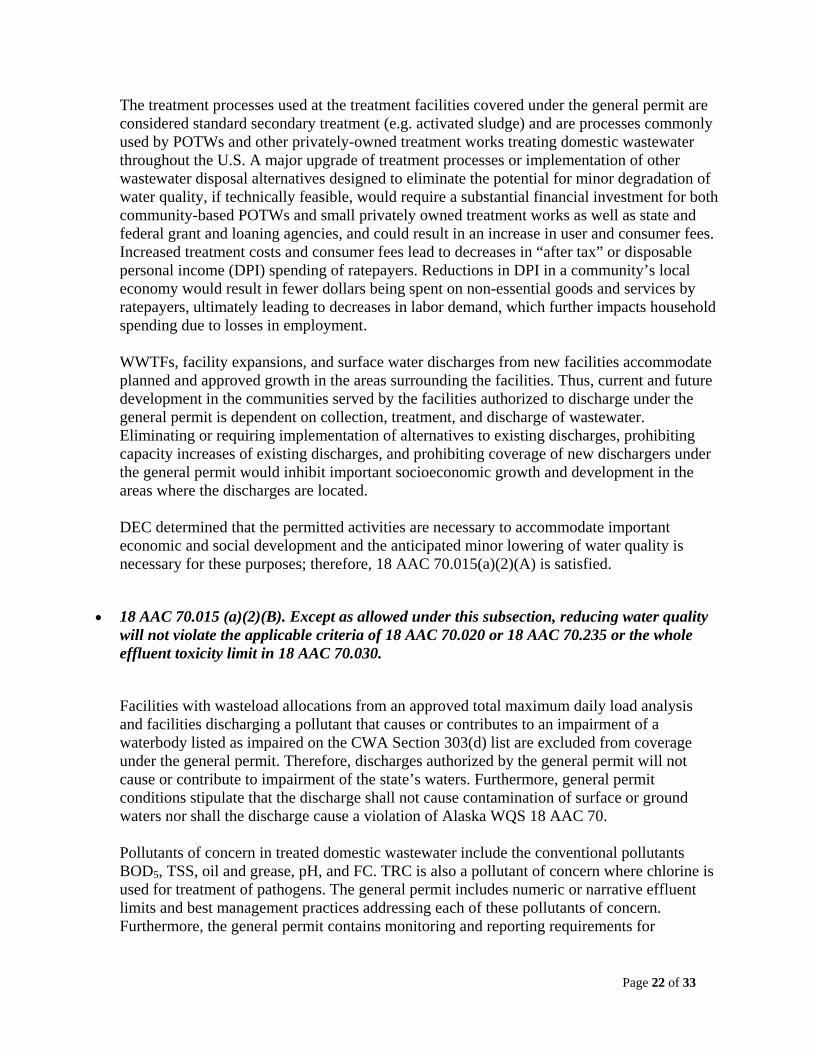
Page 22 of 33
The treatment processes used at the treatment facilities covered under the general permit are considered standard secondary treatment (e.g. activated sludge) and are processes commonly used by POTWs and other privately-owned treatment works treating domestic wastewater throughout the U.S. A major upgrade of treatment processes or implementation of other wastewater disposal alternatives designed to eliminate the potential for minor degradation of water quality, if technically feasible, would require a substantial financial investment for both community-based POTWs and small privately owned treatment works as well as state and federal grant and loaning agencies, and could result in an increase in user and consumer fees. Increased treatment costs and consumer fees lead to decreases in “after tax” or disposable personal income (DPI) spending of ratepayers. Reductions in DPI in a community’s local economy would result in fewer dollars being spent on non-essential goods and services by ratepayers, ultimately leading to decreases in labor demand, which further impacts household spending due to losses in employment.
WWTFs, facility expansions, and surface water discharges from new facilities accommodate planned and approved growth in the areas surrounding the facilities. Thus, current and future development in the communities served by the facilities authorized to discharge under the general permit is dependent on collection, treatment, and discharge of wastewater. Eliminating or requiring implementation of alternatives to existing discharges, prohibiting capacity increases of existing discharges, and prohibiting coverage of new dischargers under the general permit would inhibit important socioeconomic growth and development in the areas where the discharges are located. DEC determined that the permitted activities are necessary to accommodate important economic and social development and the anticipated minor lowering of water quality is necessary for these purposes; therefore, 18 AAC 70.015(a)(2)(A) is satisfied.
18 AAC 70.015 (a)(2)(B). Except as allowed under this subsection, reducing water quality will not violate the applicable criteria of 18 AAC 70.020 or 18 AAC 70.235 or the whole effluent toxicity limit in 18 AAC 70.030.
Facilities with wasteload allocations from an approved total maximum daily load analysis and facilities discharging a pollutant that causes or contributes to an impairment of a waterbody listed as impaired on the CWA Section 303(d) list are excluded from coverage under the general permit. Therefore, discharges authorized by the general permit will not cause or contribute to impairment of the state’s waters. Furthermore, general permit conditions stipulate that the discharge shall not cause contamination of surface or ground waters nor shall the discharge cause a violation of Alaska WQS 18 AAC 70. Pollutants of concern in treated domestic wastewater include the conventional pollutants BOD5, TSS, oil and grease, pH, and FC. TRC is also a pollutant of concern where chlorine is used for treatment of pathogens. The general permit includes numeric or narrative effluent limits and best management practices addressing each of these pollutants of concern. Furthermore, the general permit contains monitoring and reporting requirements for
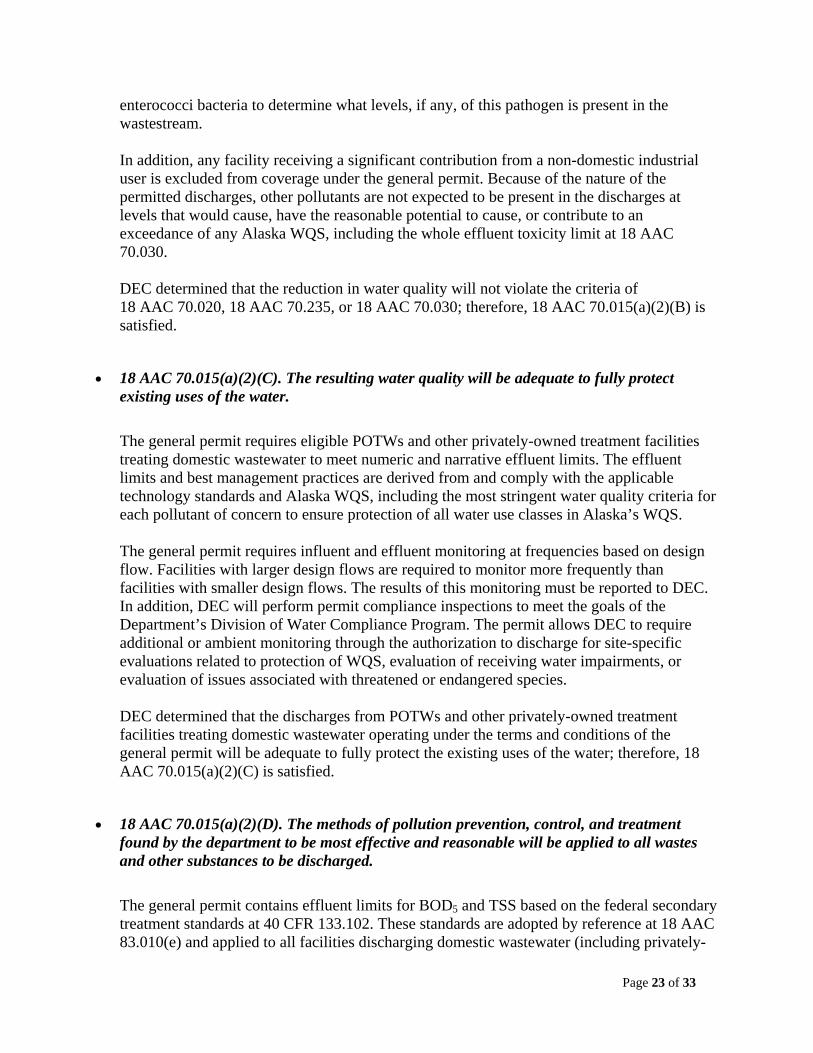
Page 23 of 33
enterococci bacteria to determine what levels, if any, of this pathogen is present in the wastestream.
In addition, any facility receiving a significant contribution from a non-domestic industrial user is excluded from coverage under the general permit. Because of the nature of the permitted discharges, other pollutants are not expected to be present in the discharges at levels that would cause, have the reasonable potential to cause, or contribute to an exceedance of any Alaska WQS, including the whole effluent toxicity limit at 18 AAC 70.030.
DEC determined that the reduction in water quality will not violate the criteria of 18 AAC 70.020, 18 AAC 70.235, or 18 AAC 70.030; therefore, 18 AAC 70.015(a)(2)(B) is satisfied.
18 AAC 70.015(a)(2)(C). The resulting water quality will be adequate to fully protect existing uses of the water.
The general permit requires eligible POTWs and other privately-owned treatment facilities treating domestic wastewater to meet numeric and narrative effluent limits. The effluent limits and best management practices are derived from and comply with the applicable technology standards and Alaska WQS, including the most stringent water quality criteria for each pollutant of concern to ensure protection of all water use classes in Alaska’s WQS. The general permit requires influent and effluent monitoring at frequencies based on design flow. Facilities with larger design flows are required to monitor more frequently than facilities with smaller design flows. The results of this monitoring must be reported to DEC. In addition, DEC will perform permit compliance inspections to meet the goals of the Department’s Division of Water Compliance Program. The permit allows DEC to require additional or ambient monitoring through the authorization to discharge for site-specific evaluations related to protection of WQS, evaluation of receiving water impairments, or evaluation of issues associated with threatened or endangered species. DEC determined that the discharges from POTWs and other privately-owned treatment facilities treating domestic wastewater operating under the terms and conditions of the general permit will be adequate to fully protect the existing uses of the water; therefore, 18 AAC 70.015(a)(2)(C) is satisfied.
18 AAC 70.015(a)(2)(D). The methods of pollution prevention, control, and treatment found by the department to be most effective and reasonable will be applied to all wastes and other substances to be discharged.
The general permit contains effluent limits for BOD5 and TSS based on the federal secondary treatment standards at 40 CFR 133.102. These standards are adopted by reference at 18 AAC 83.010(e) and applied to all facilities discharging domestic wastewater (including privately-
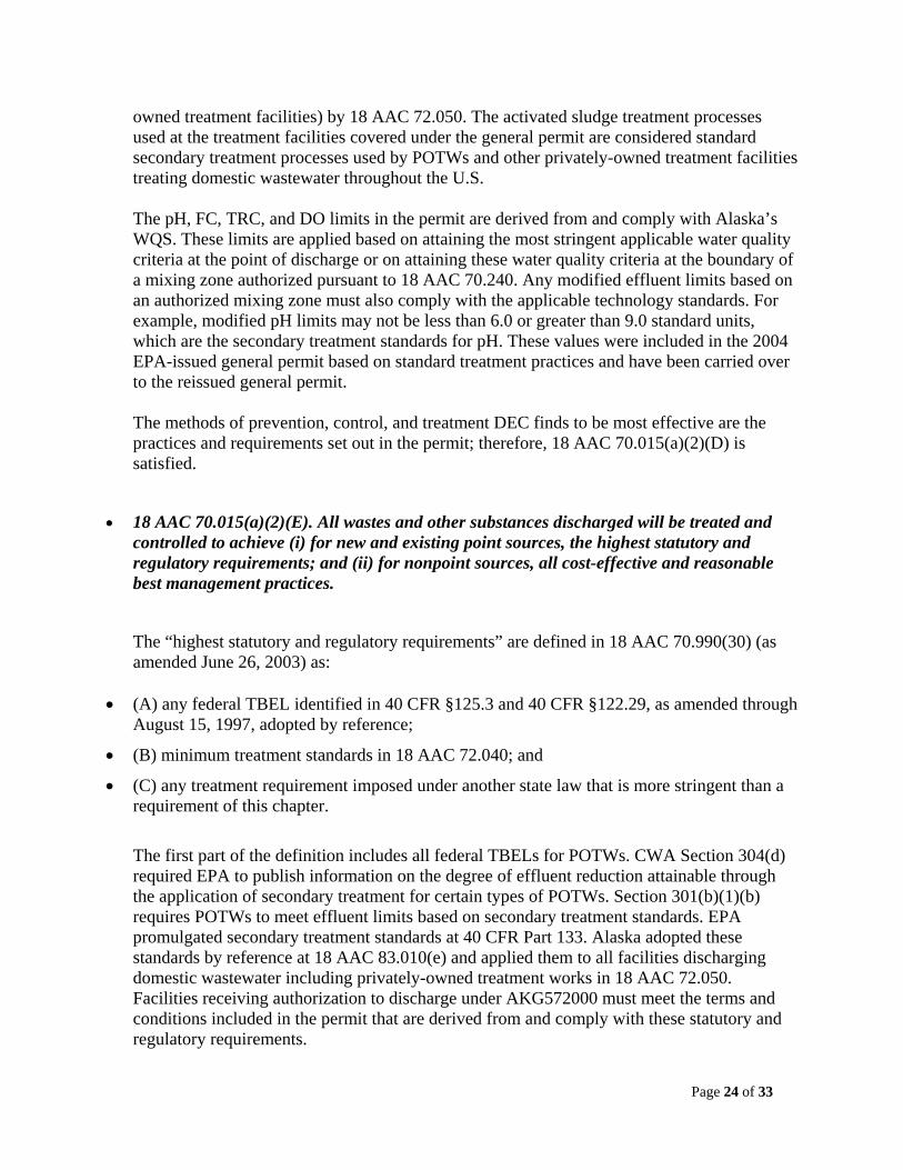
Page 24 of 33
owned treatment facilities) by 18 AAC 72.050. The activated sludge treatment processes used at the treatment facilities covered under the general permit are considered standard secondary treatment processes used by POTWs and other privately-owned treatment facilities treating domestic wastewater throughout the U.S. The pH, FC, TRC, and DO limits in the permit are derived from and comply with Alaska’s WQS. These limits are applied based on attaining the most stringent applicable water quality criteria at the point of discharge or on attaining these water quality criteria at the boundary of a mixing zone authorized pursuant to 18 AAC 70.240. Any modified effluent limits based on an authorized mixing zone must also comply with the applicable technology standards. For example, modified pH limits may not be less than 6.0 or greater than 9.0 standard units, which are the secondary treatment standards for pH. These values were included in the 2004 EPA-issued general permit based on standard treatment practices and have been carried over to the reissued general permit. The methods of prevention, control, and treatment DEC finds to be most effective are the practices and requirements set out in the permit; therefore, 18 AAC 70.015(a)(2)(D) is satisfied.
18 AAC 70.015(a)(2)(E). All wastes and other substances discharged will be treated and controlled to achieve (i) for new and existing point sources, the highest statutory and regulatory requirements; and (ii) for nonpoint sources, all cost-effective and reasonable best management practices.
The “highest statutory and regulatory requirements” are defined in 18 AAC 70.990(30) (as amended June 26, 2003) as:
(A) any federal TBEL identified in 40 CFR §125.3 and 40 CFR §122.29, as amended through August 15, 1997, adopted by reference;
(B) minimum treatment standards in 18 AAC 72.040; and
(C) any treatment requirement imposed under another state law that is more stringent than a requirement of this chapter.
The first part of the definition includes all federal TBELs for POTWs. CWA Section 304(d) required EPA to publish information on the degree of effluent reduction attainable through the application of secondary treatment for certain types of POTWs. Section 301(b)(1)(b) requires POTWs to meet effluent limits based on secondary treatment standards. EPA promulgated secondary treatment standards at 40 CFR Part 133. Alaska adopted these standards by reference at 18 AAC 83.010(e) and applied them to all facilities discharging domestic wastewater including privately-owned treatment works in 18 AAC 72.050. Facilities receiving authorization to discharge under AKG572000 must meet the terms and conditions included in the permit that are derived from and comply with these statutory and regulatory requirements.
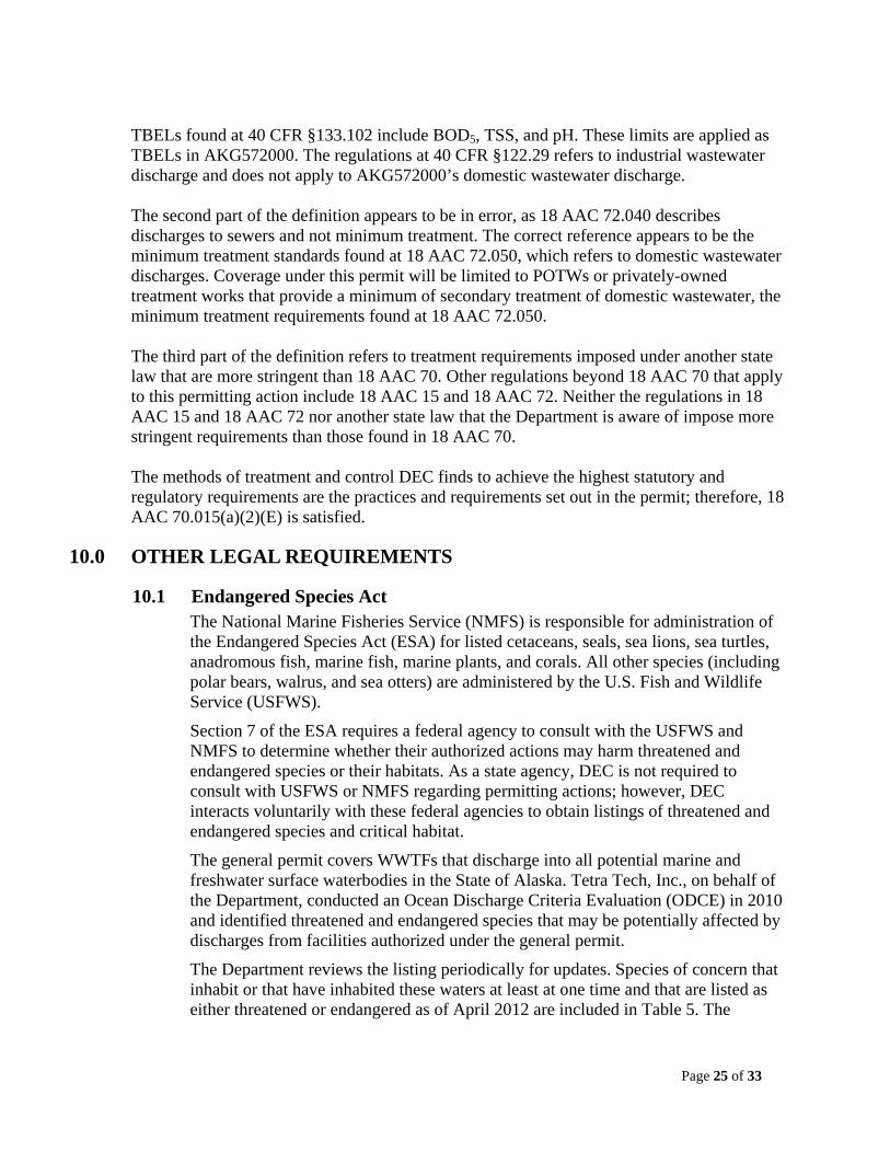
Page 25 of 33
TBELs found at 40 CFR §133.102 include BOD5, TSS, and pH. These limits are applied as TBELs in AKG572000. The regulations at 40 CFR §122.29 refers to industrial wastewater discharge and does not apply to AKG572000’s domestic wastewater discharge. The second part of the definition appears to be in error, as 18 AAC 72.040 describes discharges to sewers and not minimum treatment. The correct reference appears to be the minimum treatment standards found at 18 AAC 72.050, which refers to domestic wastewater discharges. Coverage under this permit will be limited to POTWs or privately-owned treatment works that provide a minimum of secondary treatment of domestic wastewater, the minimum treatment requirements found at 18 AAC 72.050. The third part of the definition refers to treatment requirements imposed under another state law that are more stringent than 18 AAC 70. Other regulations beyond 18 AAC 70 that apply to this permitting action include 18 AAC 15 and 18 AAC 72. Neither the regulations in 18 AAC 15 and 18 AAC 72 nor another state law that the Department is aware of impose more stringent requirements than those found in 18 AAC 70. The methods of treatment and control DEC finds to achieve the highest statutory and regulatory requirements are the practices and requirements set out in the permit; therefore, 18 AAC 70.015(a)(2)(E) is satisfied.
10.0 OTHER LEGAL REQUIREMENTS
10.1 Endangered Species Act The National Marine Fisheries Service (NMFS) is responsible for administration of the Endangered Species Act (ESA) for listed cetaceans, seals, sea lions, sea turtles, anadromous fish, marine fish, marine plants, and corals. All other species (including polar bears, walrus, and sea otters) are administered by the U.S. Fish and Wildlife Service (USFWS).
Section 7 of the ESA requires a federal agency to consult with the USFWS and NMFS to determine whether their authorized actions may harm threatened and endangered species or their habitats. As a state agency, DEC is not required to consult with USFWS or NMFS regarding permitting actions; however, DEC interacts voluntarily with these federal agencies to obtain listings of threatened and endangered species and critical habitat.
The general permit covers WWTFs that discharge into all potential marine and freshwater surface waterbodies in the State of Alaska. Tetra Tech, Inc., on behalf of the Department, conducted an Ocean Discharge Criteria Evaluation (ODCE) in 2010 and identified threatened and endangered species that may be potentially affected by discharges from facilities authorized under the general permit.
The Department reviews the listing periodically for updates. Species of concern that inhabit or that have inhabited these waters at least at one time and that are listed as either threatened or endangered as of April 2012 are included in Table 5. The
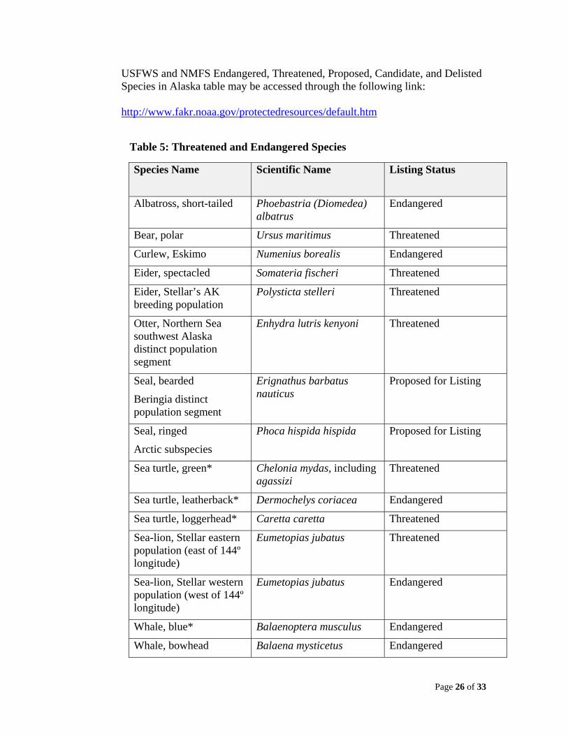
Page 26 of 33
USFWS and NMFS Endangered, Threatened, Proposed, Candidate, and Delisted Species in Alaska table may be accessed through the following link: http://www.fakr.noaa.gov/protectedresources/default.htm
Table 5: Threatened and Endangered Species
Species Name Scientific Name Listing Status
Albatross, short-tailed Phoebastria (Diomedea) albatrus
Endangered
Bear, polar Ursus maritimus Threatened
Curlew, Eskimo Numenius borealis Endangered
Eider, spectacled Somateria fischeri Threatened
Eider, Stellar’s AK breeding population
Polysticta stelleri Threatened
Otter, Northern Sea southwest Alaska distinct population segment
Enhydra lutris kenyoni Threatened
Seal, bearded
Beringia distinct population segment
Erignathus barbatus nauticus
Proposed for Listing
Seal, ringed
Arctic subspecies
Phoca hispida hispida Proposed for Listing
Sea turtle, green* Chelonia mydas, including agassizi
Threatened
Sea turtle, leatherback* Dermochelys coriacea Endangered
Sea turtle, loggerhead* Caretta caretta Threatened
Sea-lion, Stellar eastern population (east of 144º longitude)
Eumetopias jubatus Threatened
Sea-lion, Stellar western population (west of 144º longitude)
Eumetopias jubatus Endangered
Whale, blue* Balaenoptera musculus Endangered
Whale, bowhead Balaena mysticetus Endangered
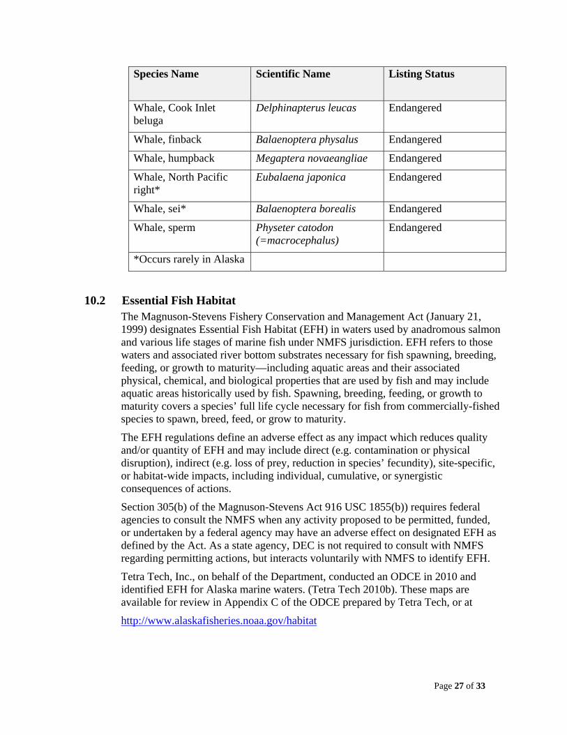
Page 27 of 33
Species Name Scientific Name Listing Status
Whale, Cook Inlet beluga
Delphinapterus leucas Endangered
Whale, finback Balaenoptera physalus Endangered
Whale, humpback Megaptera novaeangliae Endangered
Whale, North Pacific right*
Eubalaena japonica Endangered
Whale, sei* Balaenoptera borealis Endangered
Whale, sperm Physeter catodon (=macrocephalus)
Endangered
*Occurs rarely in Alaska
10.2 Essential Fish Habitat The Magnuson-Stevens Fishery Conservation and Management Act (January 21, 1999) designates Essential Fish Habitat (EFH) in waters used by anadromous salmon and various life stages of marine fish under NMFS jurisdiction. EFH refers to those waters and associated river bottom substrates necessary for fish spawning, breeding, feeding, or growth to maturity—including aquatic areas and their associated physical, chemical, and biological properties that are used by fish and may include aquatic areas historically used by fish. Spawning, breeding, feeding, or growth to maturity covers a species’ full life cycle necessary for fish from commercially-fished species to spawn, breed, feed, or grow to maturity.
The EFH regulations define an adverse effect as any impact which reduces quality and/or quantity of EFH and may include direct (e.g. contamination or physical disruption), indirect (e.g. loss of prey, reduction in species’ fecundity), site-specific, or habitat-wide impacts, including individual, cumulative, or synergistic consequences of actions.
Section 305(b) of the Magnuson-Stevens Act 916 USC 1855(b)) requires federal agencies to consult the NMFS when any activity proposed to be permitted, funded, or undertaken by a federal agency may have an adverse effect on designated EFH as defined by the Act. As a state agency, DEC is not required to consult with NMFS regarding permitting actions, but interacts voluntarily with NMFS to identify EFH.
Tetra Tech, Inc., on behalf of the Department, conducted an ODCE in 2010 and identified EFH for Alaska marine waters. (Tetra Tech 2010b). These maps are available for review in Appendix C of the ODCE prepared by Tetra Tech, or at
http://www.alaskafisheries.noaa.gov/habitat
Page 28 of 33
ADF&G also maintains regulatory and interactive maps that identify anadromous streams, fish passage, and fish inventory at:
http://www.adfg.alaska.gov/sf/SARR/AWC/index.cfm?ADFG=maps.maps
10.3 Ocean Discharge Criteria Evaluation
The Ocean Discharge Criteria establish guidelines for permitting discharges into the territorial seas, the contiguous zone and the ocean. The Department conducted an ODCE using criteria established in accordance with CWA Section 403 and 40 CFR Part 125, adopted by reference at 18 AAC 83.010(c). Based on the available information, the Department determines whether the discharge will cause unreasonable degradation of the marine environment. 40 CFR Part 125.121, adopted by reference at 18 AAC 83.010(c)(8), states unreasonable degradation of the marine environment means
a) significant adverse changes in ecosystem diversity, productivity, and stability of the biological community within the area of discharge and surrounding biological communities;
b) threat to human health through direct exposure to pollutants or through consumption of exposed aquatic organisms; or
c) loss of aesthetic, recreational, scientific or economic values which is unreasonable in relation to the benefit derived from the discharge.
40 CFR Part 125.122, adopted by reference at 18 AAC 83.010(c)(8), provides 10 criteria to consider in the determination of whether there is unreasonable degradation or irreparable harm. The 10 criteria include: the amount and nature of the pollutants; the potential transport of the pollutants; the character and uses of the receiving water and its biological communities; the importance of the receiving water area; the existence of special aquatic sites (including parks, refuges, etc.); any applicable requirements of an approved Coastal Zone Management plan; and potential impacts on water quality, ecological health, and human health.
After consideration of these criteria, the Department has determined that discharges authorized by the permit and discharged in accordance with the requirements of the permit will not cause unreasonable degradation of the receiving waters.
The general permit is for authorization of small facilities treating domestic wastewater only. Facilities are required to treat the wastewater to secondary treatment standards and comply with WQS either at the end of the pipe prior to discharge, or at the boundary of an authorized mixing zone. Due to the size and nature of the discharge and compliance with WQS, unreasonable degradation should not occur when facilities are operating under the terms and conditions of the permit.
10.4 Permit Expiration
The permit will expire five years from the effective date of the permit.
Page 29 of 33
REFERENCES DEC (Alaska Department of Environmental Conservation). 2003. Alaska water quality criteria
manual for toxic and other deleterious organic and inorganic substances. State of Alaska, Department of Environmental Conservation.
DEC. 2003. 18 AAC 70 Water quality standards, as amended through June 26, 2003. State of
Alaska, Department of Environmental Conservation. DEC. 2009. 18 AAC 70 Water quality standards, as amended through September 19, 2009. State
of Alaska, Department of Environmental Conservation. DEC. 2010. Interim antidegradation implementation methods. State of Alaska, Department of
Environmental Conservation. EPA (Environmental Protection Agency). 1991. Technical support document for water quality-
based toxics control. US Environmental Protection Agency, Office of Water, EPA /505-2-90-001, Washington D.C.
EPA. 1986. Ambient water quality criteria for baceteria-1986. US Environmental Protection
Agency, Office of Water, EPA 440/5-84-002, Washington D.C. EPA. 2004. Implementation guidance for ambient water quality criteria for bacteria. US
Environmental Protection Agency, Office of Water, EPA 823/B-04-002, Washington D.C. Tetra Tech, Inc. 2010a. Unpublished. Alaska general permits for small wastewater treatment
plants, fact sheet discussion—antidegradation policy implementation. Located at: Alaska Department of Environmental Conservation, 610 University Avenue, Fairbanks, Alaska and Alaska Department of Environmental Conservation 555 Cordova Street, Anchorage, Alaska.
Tetra Tech, Inc. 2010b. Unpublished. Ocean discharge criteria evaluation, APDES general
permit small publicly owned treatment works and other small treatment works providing secondary treatment of domestic sewage discharging to marine water in Alaska, APDES general permit No. AKG57M000. Located at: Alaska Department of Environmental Conservation, 610 University Avenue, Fairbanks, Alaska and Alaska Department of Environmental Conservation 555 Cordova Street, Anchorage, Alaska.
USFWS (U.S. Fish and Wildlife Service). 2010. U.S. Fish & Wildlife Service, endangered
species. http://alaska.fws.gov/fisheries/endangered/consultation_guide.htm. Accessed February 15, 2011.
Water Pollution Control Federation. 1976. Chlorination of wastewater, manual of practice no. 4. Moore & Moore, Washington D.C
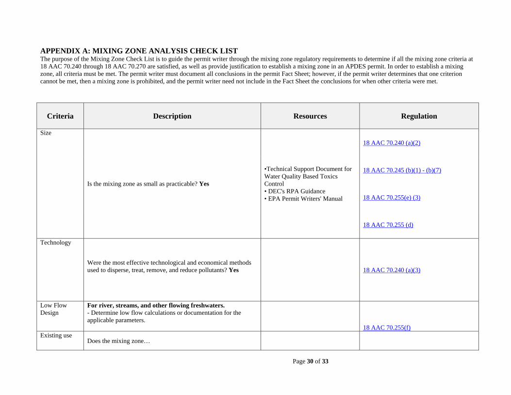
Page 30 of 33
APPENDIX A: MIXING ZONE ANALYSIS CHECK LIST The purpose of the Mixing Zone Check List is to guide the permit writer through the mixing zone regulatory requirements to determine if all the mixing zone criteria at 18 AAC 70.240 through 18 AAC 70.270 are satisfied, as well as provide justification to establish a mixing zone in an APDES permit. In order to establish a mixing zone, all criteria must be met. The permit writer must document all conclusions in the permit Fact Sheet; however, if the permit writer determines that one criterion cannot be met, then a mixing zone is prohibited, and the permit writer need not include in the Fact Sheet the conclusions for when other criteria were met.
Criteria Description Resources Regulation
Size
Is the mixing zone as small as practicable? Yes
•Technical Support Document for Water Quality Based Toxics Control • DEC's RPA Guidance • EPA Permit Writers' Manual
18 AAC 70.240 (a)(2)
18 AAC 70.245 (b)(1) - (b)(7)
18 AAC 70.255(e) (3)
18 AAC 70.255 (d)
Technology
Were the most effective technological and economical methods used to disperse, treat, remove, and reduce pollutants? Yes
18 AAC 70.240 (a)(3)
Low Flow Design
For river, streams, and other flowing freshwaters. - Determine low flow calculations or documentation for the applicable parameters.
18 AAC 70.255(f)
Existing use Does the mixing zone…
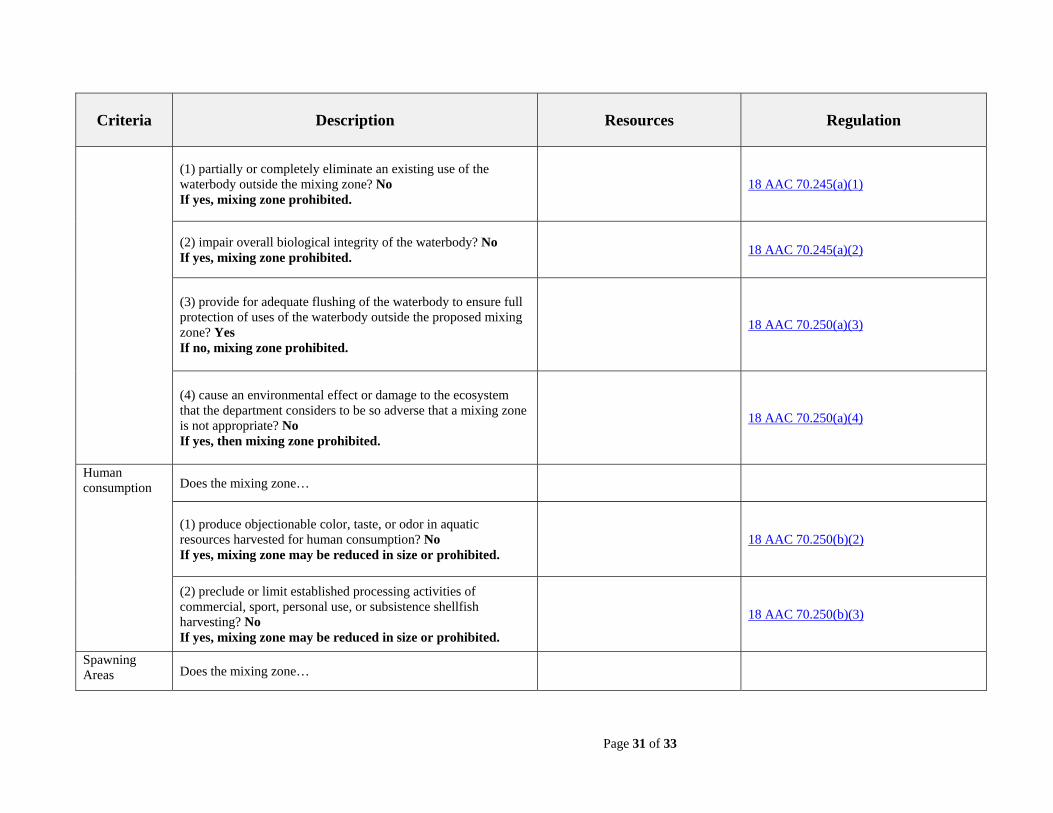
Page 31 of 33
Criteria Description Resources Regulation
(1) partially or completely eliminate an existing use of the waterbody outside the mixing zone? No If yes, mixing zone prohibited.
18 AAC 70.245(a)(1)
(2) impair overall biological integrity of the waterbody? No If yes, mixing zone prohibited.
18 AAC 70.245(a)(2)
(3) provide for adequate flushing of the waterbody to ensure full protection of uses of the waterbody outside the proposed mixing zone? Yes If no, mixing zone prohibited.
18 AAC 70.250(a)(3)
(4) cause an environmental effect or damage to the ecosystem that the department considers to be so adverse that a mixing zone is not appropriate? No If yes, then mixing zone prohibited.
18 AAC 70.250(a)(4)
Human consumption Does the mixing zone…
(1) produce objectionable color, taste, or odor in aquatic resources harvested for human consumption? No If yes, mixing zone may be reduced in size or prohibited.
18 AAC 70.250(b)(2)
(2) preclude or limit established processing activities of commercial, sport, personal use, or subsistence shellfish harvesting? No If yes, mixing zone may be reduced in size or prohibited.
18 AAC 70.250(b)(3)
Spawning Areas Does the mixing zone…
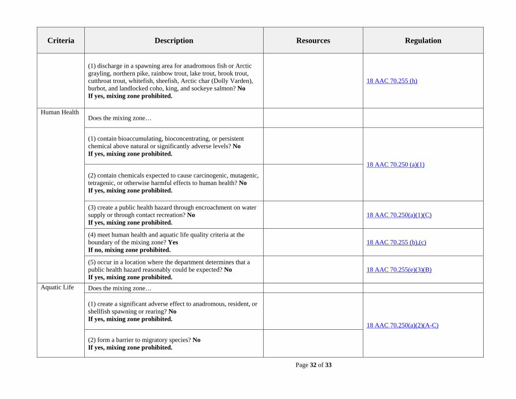
Page 32 of 33
Criteria Description Resources Regulation
(1) discharge in a spawning area for anadromous fish or Arctic grayling, northern pike, rainbow trout, lake trout, brook trout, cutthroat trout, whitefish, sheefish, Arctic char (Dolly Varden), burbot, and landlocked coho, king, and sockeye salmon? No If yes, mixing zone prohibited.
18 AAC 70.255 (h)
Human Health Does the mixing zone…
(1) contain bioaccumulating, bioconcentrating, or persistent chemical above natural or significantly adverse levels? No If yes, mixing zone prohibited.
18 AAC 70.250 (a)(1)
(2) contain chemicals expected to cause carcinogenic, mutagenic, tetragenic, or otherwise harmful effects to human health? No If yes, mixing zone prohibited.
(3) create a public health hazard through encroachment on water supply or through contact recreation? No If yes, mixing zone prohibited.
18 AAC 70.250(a)(1)(C)
(4) meet human health and aquatic life quality criteria at the boundary of the mixing zone? Yes If no, mixing zone prohibited.
18 AAC 70.255 (b),(c)
(5) occur in a location where the department determines that a public health hazard reasonably could be expected? No If yes, mixing zone prohibited.
18 AAC 70.255(e)(3)(B)
Aquatic Life Does the mixing zone…
(1) create a significant adverse effect to anadromous, resident, or shellfish spawning or rearing? No If yes, mixing zone prohibited.
18 AAC 70.250(a)(2)(A-C)
(2) form a barrier to migratory species? No If yes, mixing zone prohibited.
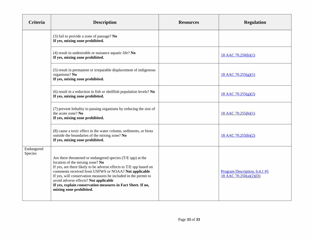
Page 33 of 33
Criteria Description Resources Regulation
(3) fail to provide a zone of passage? No If yes, mixing zone prohibited.
(4) result in undesirable or nuisance aquatic life? No If yes, mixing zone prohibited.
18 AAC 70.250(b)(1)
(5) result in permanent or irreparable displacement of indigenous organisms? No If yes, mixing zone prohibited.
18 AAC 70.255(g)(1)
(6) result in a reduction in fish or shellfish population levels? No If yes, mixing zone prohibited.
18 AAC 70.255(g)(2)
(7) prevent lethality to passing organisms by reducing the size of the acute zone? No If yes, mixing zone prohibited.
18 AAC 70.255(b)(1)
(8) cause a toxic effect in the water column, sediments, or biota outside the boundaries of the mixing zone? No If yes, mixing zone prohibited.
18 AAC 70.255(b)(2)
Endangered Species
Are there threatened or endangered species (T/E spp) at the location of the mixing zone? No If yes, are there likely to be adverse effects to T/E spp based on comments received from USFWS or NOAA? Not applicable If yes, will conservation measures be included in the permit to avoid adverse effects? Not applicable If yes, explain conservation measures in Fact Sheet. If no, mixing zone prohibited.
Program Description, 6.4.1 #5 18 AAC 70.250(a)(2)(D)
ABTP Operations and Maintenance Plan
Appendix BUPCPs
UPCP: Head-worksPlant: Auke Bay Wastewater Treatment FacilityAuthor: Ryan HosmanDate: May 2015
SummaryThe head-works of the facility is a physical process including grit removal and
pre-screening that do not require any biological or chemical treatment. Here the rawwastewater passes through this unit process which is designed to remove grit, rags,trash, or other miscellaneous debris to protect pumps, pipes, equipment, and theperformance of other downstream processes.
Process OverviewAfter the influent enters the facility, it flows through a grit chamber that decreases
the velocity of the wastewater enough to allow heavier inorganic matter to settle out.Then the flow enters another chamber and passes through a bar screen leaving behindrags, trash and other miscellaneous debris. If flow cannot pass through the bar screen,there is a v-notch weir at the top of this box for wastewater to overflow into the contactchamber. Once the flow passes through the bar screen it then goes through a MuffinMonster to ensure any larger material that will plug up pipes or pumps is cut down tosize.
Unit Process Physical InformationThe influent enters the facility through a 10” pipe with a 10” gate valve. The grit
channel is 4’ long, 2’ wide, and 4.5’ tall with a round opening connected to the barscreen channel. The bar screen channel is 3.75’ long, 2’ wide, and 2.5’ tall with a v-notch weir upstream of the screen. The bar screen is composed of 23 rods spaced aninch from each other at a 45o angle. Connected downstream of the bar screen channelis a model 30005 electric drive Muffin Monster with a small overflow section betweenthem. The grinder and bar screen section are located above the contact zone whereflow is discharged.
Operational Parameters and Process TheoryThe wastewater contains food, nutrients, and microorganisms that are very
important to the biological treatment process but is also composed of excessiveamounts of grit, rags, trash, or miscellaneous debris. Grit is very abrasive and candamage most anything that it contacts. Organic solids tend to be lighter and less dense
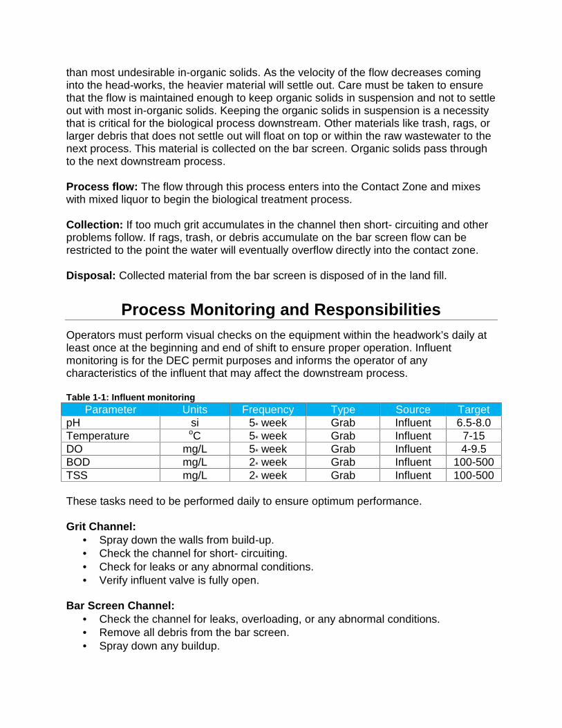
than most undesirable in-organic solids. As the velocity of the flow decreases cominginto the head-works, the heavier material will settle out. Care must be taken to ensurethat the flow is maintained enough to keep organic solids in suspension and not to settleout with most in-organic solids. Keeping the organic solids in suspension is a necessitythat is critical for the biological process downstream. Other materials like trash, rags, orlarger debris that does not settle out will float on top or within the raw wastewater to thenext process. This material is collected on the bar screen. Organic solids pass throughto the next downstream process.
Process flow: The flow through this process enters into the Contact Zone and mixeswith mixed liquor to begin the biological treatment process.
Collection: If too much grit accumulates in the channel then short- circuiting and otherproblems follow. If rags, trash, or debris accumulate on the bar screen flow can berestricted to the point the water will eventually overflow directly into the contact zone.
Disposal: Collected material from the bar screen is disposed of in the land fill.
Process Monitoring and ResponsibilitiesOperators must perform visual checks on the equipment within the headwork’s daily atleast once at the beginning and end of shift to ensure proper operation. Influentmonitoring is for the DEC permit purposes and informs the operator of anycharacteristics of the influent that may affect the downstream process.
Table 1-1: Influent monitoringParameter Units Frequency Type Source Target
pH si 5* week Grab Influent 6.5-8.0Temperature oC 5* week Grab Influent 7-15DO mg/L 5* week Grab Influent 4-9.5BOD mg/L 2* week Grab Influent 100-500TSS mg/L 2* week Grab Influent 100-500
These tasks need to be performed daily to ensure optimum performance.
Grit Channel: Spray down the walls from build-up. Check the channel for short- circuiting. Check for leaks or any abnormal conditions. Verify influent valve is fully open.
Bar Screen Channel: Check the channel for leaks, overloading, or any abnormal conditions. Remove all debris from the bar screen. Spray down any buildup.
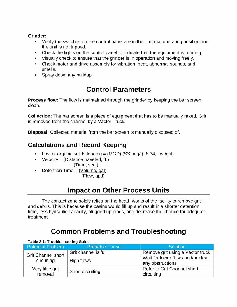
Grinder: Verify the switches on the control panel are in their normal operating position and
the unit is not tripped. Check the lights on the control panel to indicate that the equipment is running. Visually check to ensure that the grinder is in operation and moving freely. Check motor and drive assembly for vibration, heat, abnormal sounds, and
smells. Spray down any buildup.
Control ParametersProcess flow: The flow is maintained through the grinder by keeping the bar screenclean.
Collection: The bar screen is a piece of equipment that has to be manually raked. Gritis removed from the channel by a Vactor Truck.
Disposal: Collected material from the bar screen is manually disposed of.
Calculations and Record Keeping Lbs. of organic solids loading = (MGD) (SS, mg/l) (8.34, lbs./gal) Velocity = (Distance traveled, ft.)
(Time, sec.) Detention Time = (Volume, gal)
(Flow, gpd)
Impact on Other Process UnitsThe contact zone solely relies on the head- works of the facility to remove grit
and debris. This is because the basins would fill up and result in a shorter detentiontime, less hydraulic capacity, plugged up pipes, and decrease the chance for adequatetreatment.
Common Problems and TroubleshootingTable 2-1: Troubleshooting GuidePotential Problem Probable Cause Solution
Grit Channel shortcircuiting
Grit channel is full Remove grit using a Vactor truck
High flows Wait for lower flows and/or clearany obstructions
Very little gritremoval Short circuiting Refer to Grit Channel short
circuiting
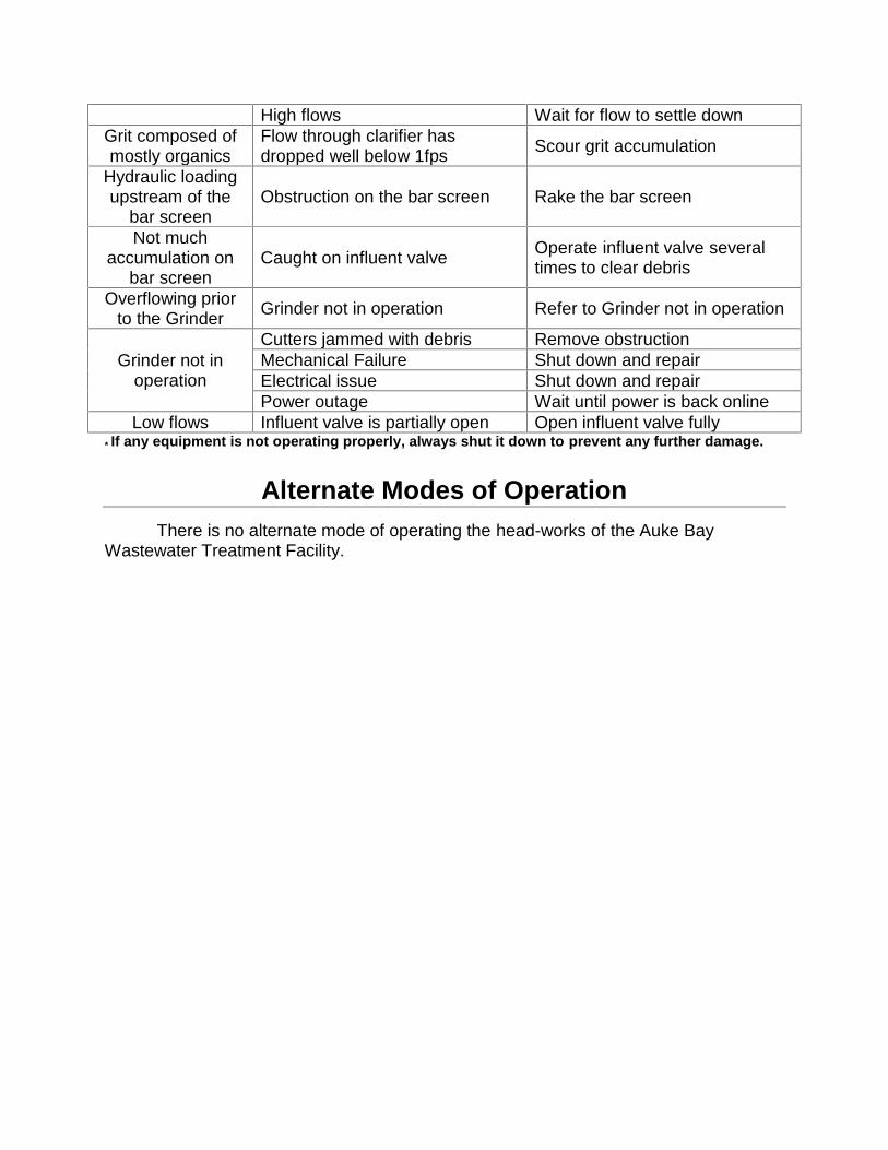
High flows Wait for flow to settle downGrit composed ofmostly organics
Flow through clarifier hasdropped well below 1fps Scour grit accumulation
Hydraulic loadingupstream of the
bar screenObstruction on the bar screen Rake the bar screen
Not muchaccumulation on
bar screenCaught on influent valve Operate influent valve several
times to clear debris
Overflowing priorto the Grinder Grinder not in operation Refer to Grinder not in operation
Grinder not inoperation
Cutters jammed with debris Remove obstructionMechanical Failure Shut down and repairElectrical issue Shut down and repairPower outage Wait until power is back online
Low flows Influent valve is partially open Open influent valve fully* If any equipment is not operating properly, always shut it down to prevent any further damage.
Alternate Modes of OperationThere is no alternate mode of operating the head-works of the Auke Bay
Wastewater Treatment Facility.
UPCP: Contact ZonePlant: Auke Bay Wastewater Treatment FacilityAuthor: Ryan HosmanDate: May 2015
SummaryThe contact zone is a critical component of the biological treatment process that
uses oxygen consuming bacteria to adsorb “food” from the incoming waste. One of themain aspects involved in the contact zone of the contact stabilization process is theadsorption of carbonaceous material. In any aeration system, where phosphate isavailable as “energy”, bacteria will adsorb organic or inorganic carbonaceous materialas “food”. Adsorption is the gathering of gas, liquid, or dissolved solid on the surface ofanother material which is performed in only a short period of time.
Process OverviewThe pre- screened wastewater enters this process through the grinder or over the
top of the bar screen box when flow is not permitted through the bar screen. Once itenters the basin it is introduced to the dissolved oxygen and mixed with the existingsolids and microorganisms. This mixture is known as mixed liquor suspended solids/activated sludge. The dissolved oxygen is provided by forcing oxygen into the waterthrough the use of blowers and diffusers. The level within the contact zone ishydraulically maintained. As wastewater and re-aerated sludge is entering into thebasin, mixed liquor flows to the “New Secondary Clarifier.” The short detention time inthis tank permits adsorption but not long enough to provide absorption. Activated sludgeis returned to the contact zone from the re-aeration zone thus reintroducing the“starved” microorganisms to the incoming food source.
Unit Process Physical InformationThe Contact Zone is a 12,985 gallon tank on the outside section of the existing
package plant. There is one 2.5” diffuser header with 12 diffusers on it with a 2.5” valve.This header is plumbed to a 26.5’ tubular tank underneath the catwalk supporting it fromeach side across the top of the package plant. This tank is plumbed to two positivedisplacement blowers with a Kunkle PRV on each blower. The blowers are belt drivenby a 15 HP Tatlung Co. motor and a 15 HP Emerson motor.
Operational Parameters and Process TheoryContained in this basin are massive microbiology colonies that are cultured from
the raw wastewater. The microorganisms chosen to be cultured in this process areaerobes. These aerobes are desirable because they do not normally produce foul odors
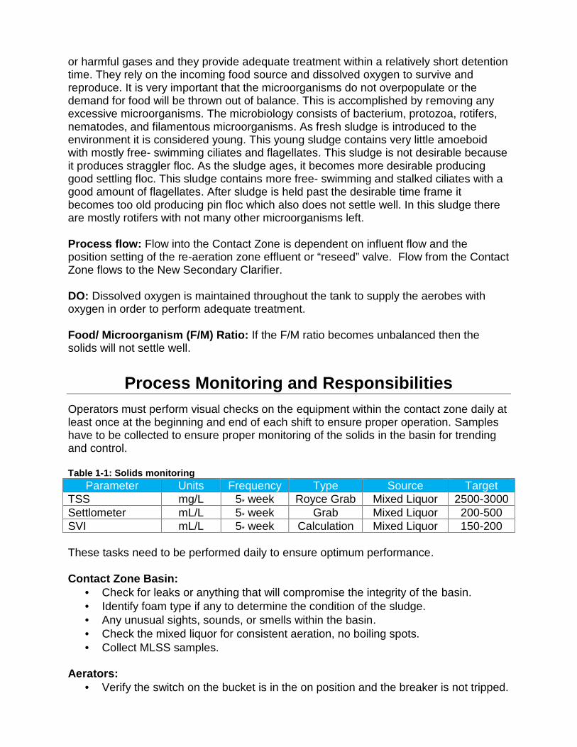
or harmful gases and they provide adequate treatment within a relatively short detentiontime. They rely on the incoming food source and dissolved oxygen to survive andreproduce. It is very important that the microorganisms do not overpopulate or thedemand for food will be thrown out of balance. This is accomplished by removing anyexcessive microorganisms. The microbiology consists of bacterium, protozoa, rotifers,nematodes, and filamentous microorganisms. As fresh sludge is introduced to theenvironment it is considered young. This young sludge contains very little amoeboidwith mostly free- swimming ciliates and flagellates. This sludge is not desirable becauseit produces straggler floc. As the sludge ages, it becomes more desirable producinggood settling floc. This sludge contains more free- swimming and stalked ciliates with agood amount of flagellates. After sludge is held past the desirable time frame itbecomes too old producing pin floc which also does not settle well. In this sludge thereare mostly rotifers with not many other microorganisms left.
Process flow: Flow into the Contact Zone is dependent on influent flow and theposition setting of the re-aeration zone effluent or “reseed” valve. Flow from the ContactZone flows to the New Secondary Clarifier.
DO: Dissolved oxygen is maintained throughout the tank to supply the aerobes withoxygen in order to perform adequate treatment.
Food/ Microorganism (F/M) Ratio: If the F/M ratio becomes unbalanced then thesolids will not settle well.
Process Monitoring and ResponsibilitiesOperators must perform visual checks on the equipment within the contact zone daily atleast once at the beginning and end of each shift to ensure proper operation. Sampleshave to be collected to ensure proper monitoring of the solids in the basin for trendingand control.
Table 1-1: Solids monitoringParameter Units Frequency Type Source Target
TSS mg/L 5* week Royce Grab Mixed Liquor 2500-3000Settlometer mL/L 5* week Grab Mixed Liquor 200-500SVI mL/L 5* week Calculation Mixed Liquor 150-200
These tasks need to be performed daily to ensure optimum performance.
Contact Zone Basin: Check for leaks or anything that will compromise the integrity of the basin. Identify foam type if any to determine the condition of the sludge. Any unusual sights, sounds, or smells within the basin. Check the mixed liquor for consistent aeration, no boiling spots. Collect MLSS samples.
Aerators: Verify the switch on the bucket is in the on position and the breaker is not tripped.
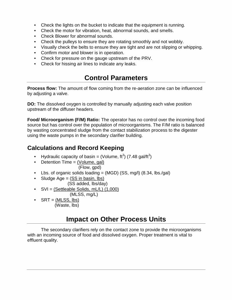
Check the lights on the bucket to indicate that the equipment is running. Check the motor for vibration, heat, abnormal sounds, and smells. Check Blower for abnormal sounds. Check the pulleys to ensure they are rotating smoothly and not wobbly. Visually check the belts to ensure they are tight and are not slipping or whipping. Confirm motor and blower is in operation. Check for pressure on the gauge upstream of the PRV. Check for hissing air lines to indicate any leaks.
Control ParametersProcess flow: The amount of flow coming from the re-aeration zone can be influencedby adjusting a valve.
DO: The dissolved oxygen is controlled by manually adjusting each valve positionupstream of the diffuser headers.
Food/ Microorganism (F/M) Ratio: The operator has no control over the incoming foodsource but has control over the population of microorganisms. The F/M ratio is balancedby wasting concentrated sludge from the contact stabilization process to the digesterusing the waste pumps in the secondary clarifier building.
Calculations and Record Keeping Hydraulic capacity of basin = (Volume, ft3) (7.48 gal/ft3) Detention Time = (Volume, gal)
(Flow, gpd) Lbs. of organic solids loading = (MGD) (SS, mg/l) (8.34, lbs./gal) Sludge Age = (SS in basin, lbs)
(SS added, lbs/day) SVI = (Settleable Solids, mL/L) (1,000)
(MLSS, mg/L) SRT = (MLSS, lbs)
(Waste, lbs)
Impact on Other Process UnitsThe secondary clarifiers rely on the contact zone to provide the microorganisms
with an incoming source of food and dissolved oxygen. Proper treatment is vital toeffluent quality.
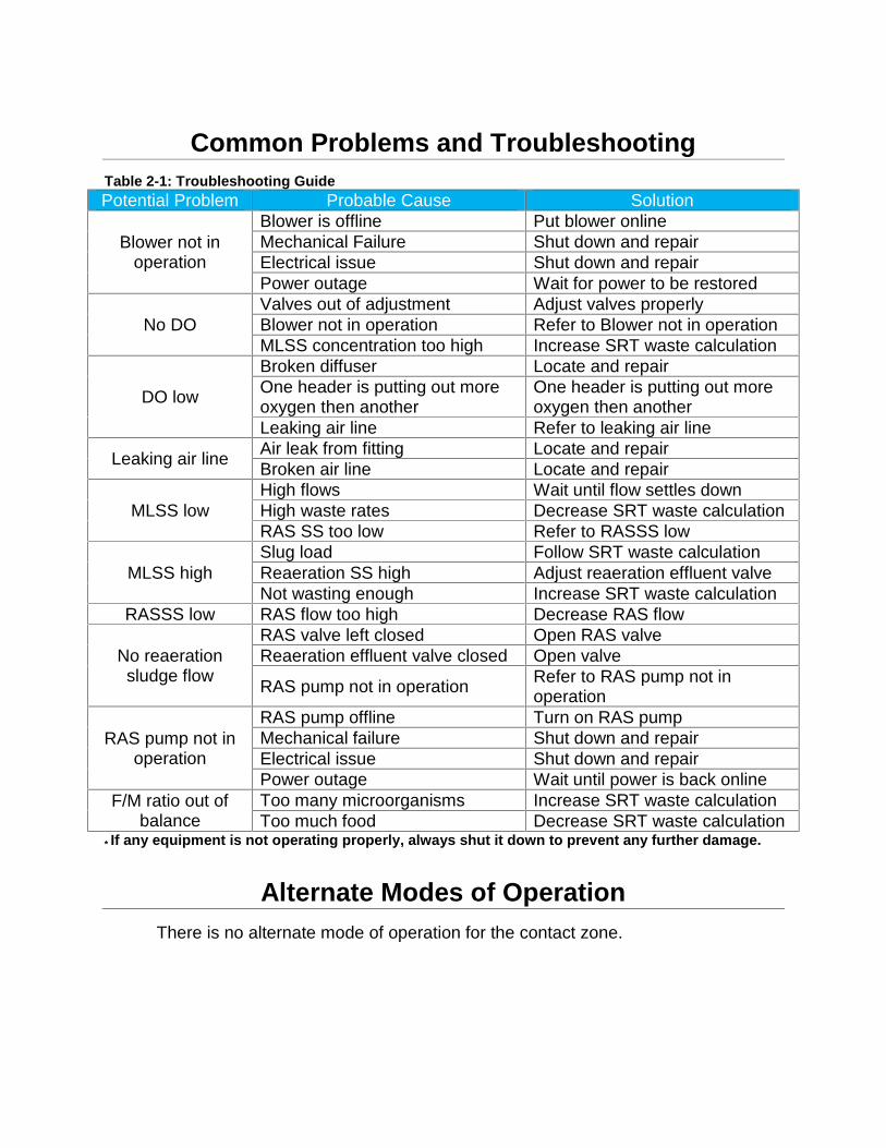
Common Problems and TroubleshootingTable 2-1: Troubleshooting GuidePotential Problem Probable Cause Solution
Blower not inoperation
Blower is offline Put blower onlineMechanical Failure Shut down and repairElectrical issue Shut down and repairPower outage Wait for power to be restored
No DOValves out of adjustment Adjust valves properlyBlower not in operation Refer to Blower not in operationMLSS concentration too high Increase SRT waste calculation
DO low
Broken diffuser Locate and repairOne header is putting out moreoxygen then another
One header is putting out moreoxygen then another
Leaking air line Refer to leaking air line
Leaking air line Air leak from fitting Locate and repairBroken air line Locate and repair
MLSS lowHigh flows Wait until flow settles downHigh waste rates Decrease SRT waste calculationRAS SS too low Refer to RASSS low
MLSS highSlug load Follow SRT waste calculationReaeration SS high Adjust reaeration effluent valveNot wasting enough Increase SRT waste calculation
RASSS low RAS flow too high Decrease RAS flow
No reaerationsludge flow
RAS valve left closed Open RAS valveReaeration effluent valve closed Open valve
RAS pump not in operation Refer to RAS pump not inoperation
RAS pump not inoperation
RAS pump offline Turn on RAS pumpMechanical failure Shut down and repairElectrical issue Shut down and repairPower outage Wait until power is back online
F/M ratio out ofbalance
Too many microorganisms Increase SRT waste calculationToo much food Decrease SRT waste calculation
* If any equipment is not operating properly, always shut it down to prevent any further damage.
Alternate Modes of OperationThere is no alternate mode of operation for the contact zone.
UPCP: Secondary ClarifiersPlant: Auke Bay Wastewater Treatment FacilityAuthor: Ryan HosmanDate: May 2015
SummaryThe secondary clarifier process allows the opportunity for microbial solids to
settle by gravity and separate from the treated water. Solids are either returned back tothe treatment system or are removed completely. Floatable material and scum iscollected then removed from this process for further treatment. The supernatantoverflows the New Clarifier and is directed through the Old Clarifier which is considereda “Polishing Clarifier.” Then it is directed to the Sodium Hypochlorite disinfectionprocess for final treatment.
Due to limitations on operational control of secondary clarifier performance it isimperative that upstream processes be optimized to ensure high quality effluent isdischarged to the mixing zone.
Process OverviewAs the mixed liquor leaves the Contact Zone, it flows through piping which is
routed through the digester and into the New Clarifier center ring. Flow enters theclarifier through the center ring in an upward direction below the water line. Here themicrobial solids have the opportunity to settle by gravity and separation from the treatedwater begins. The treated water (supernatant) hydraulically flows over the clarifier’s v-notch weirs where it gravity flows within the launder through a pipe to the Old Clarifierfor further clarification. The settled sludge is continually collected and transferred to theSludge Well within the quiescent zone at the bottom of the clarifier. The well is filled withsolids by scraper blades attached at an angle to a rotating clarifier mechanism. Thesesolids are then removed by the use of a centrifugal RAS pump and discharged into theReaeration Zone. A determined portion of the RAS is removed from the system on aregular basis to control the microbial population and keep the F/M ratio in balance. Thissludge flow, Waste Activated Sludge (WAS), is a main key in maintaining a properSolids Retention Time (SRT) within the activated sludge system. A skimming deviceattached to the rotating mechanism is utilized on the clarifier surface. This device skimsscum and floatables from the clarifier surface and deposits them in a scum collectiontrough where the contents flow to the digester with the assist of an airlift pump.
Once the supernatant leaves the New Clarifier, it flows through the digester andenters from the edge of the Old Clarifier below the water line. This clarifier is considereda “Polishing Clarifier” since it is in series and does not receive the same organic load.Here any solids that were not removed by the New Clarifier have the opportunity to beremoved by this one. Solids are removed the same way as the New Clarifier exceptthrough the use of an airlift pump. Supernatant exits this clarifier opposite from the side
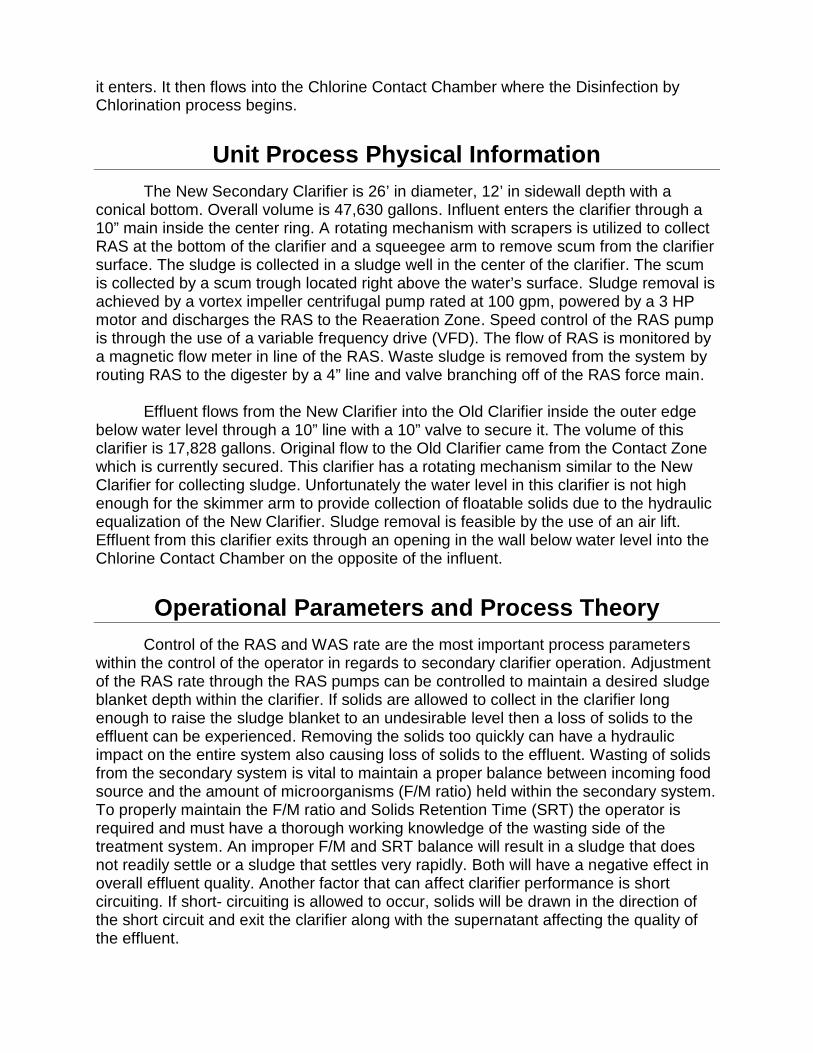
it enters. It then flows into the Chlorine Contact Chamber where the Disinfection byChlorination process begins.
Unit Process Physical InformationThe New Secondary Clarifier is 26’ in diameter, 12’ in sidewall depth with a
conical bottom. Overall volume is 47,630 gallons. Influent enters the clarifier through a10” main inside the center ring. A rotating mechanism with scrapers is utilized to collectRAS at the bottom of the clarifier and a squeegee arm to remove scum from the clarifiersurface. The sludge is collected in a sludge well in the center of the clarifier. The scumis collected by a scum trough located right above the water’s surface. Sludge removal isachieved by a vortex impeller centrifugal pump rated at 100 gpm, powered by a 3 HPmotor and discharges the RAS to the Reaeration Zone. Speed control of the RAS pumpis through the use of a variable frequency drive (VFD). The flow of RAS is monitored bya magnetic flow meter in line of the RAS. Waste sludge is removed from the system byrouting RAS to the digester by a 4” line and valve branching off of the RAS force main.
Effluent flows from the New Clarifier into the Old Clarifier inside the outer edgebelow water level through a 10” line with a 10” valve to secure it. The volume of thisclarifier is 17,828 gallons. Original flow to the Old Clarifier came from the Contact Zonewhich is currently secured. This clarifier has a rotating mechanism similar to the NewClarifier for collecting sludge. Unfortunately the water level in this clarifier is not highenough for the skimmer arm to provide collection of floatable solids due to the hydraulicequalization of the New Clarifier. Sludge removal is feasible by the use of an air lift.Effluent from this clarifier exits through an opening in the wall below water level into theChlorine Contact Chamber on the opposite of the influent.
Operational Parameters and Process TheoryControl of the RAS and WAS rate are the most important process parameters
within the control of the operator in regards to secondary clarifier operation. Adjustmentof the RAS rate through the RAS pumps can be controlled to maintain a desired sludgeblanket depth within the clarifier. If solids are allowed to collect in the clarifier longenough to raise the sludge blanket to an undesirable level then a loss of solids to theeffluent can be experienced. Removing the solids too quickly can have a hydraulicimpact on the entire system also causing loss of solids to the effluent. Wasting of solidsfrom the secondary system is vital to maintain a proper balance between incoming foodsource and the amount of microorganisms (F/M ratio) held within the secondary system.To properly maintain the F/M ratio and Solids Retention Time (SRT) the operator isrequired and must have a thorough working knowledge of the wasting side of thetreatment system. An improper F/M and SRT balance will result in a sludge that doesnot readily settle or a sludge that settles very rapidly. Both will have a negative effect inoverall effluent quality. Another factor that can affect clarifier performance is shortcircuiting. If short- circuiting is allowed to occur, solids will be drawn in the direction ofthe short circuit and exit the clarifier along with the supernatant affecting the quality ofthe effluent.
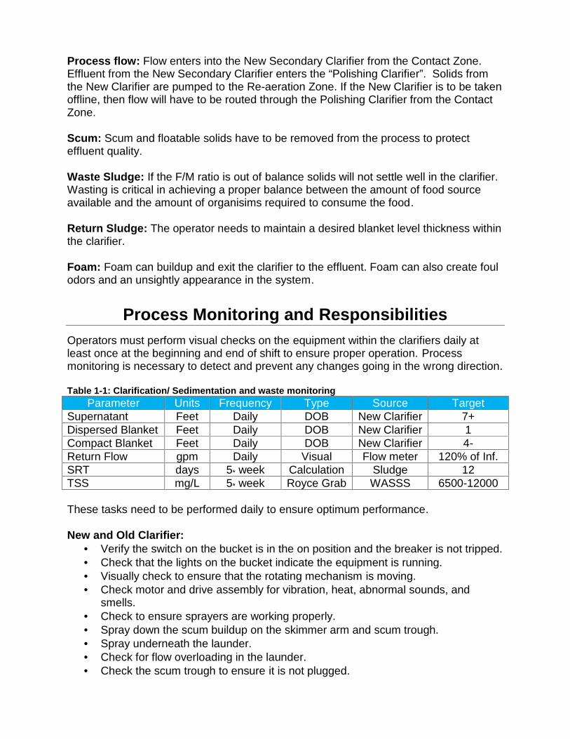
Process flow: Flow enters into the New Secondary Clarifier from the Contact Zone.Effluent from the New Secondary Clarifier enters the “Polishing Clarifier”. Solids fromthe New Clarifier are pumped to the Re-aeration Zone. If the New Clarifier is to be takenoffline, then flow will have to be routed through the Polishing Clarifier from the ContactZone.
Scum: Scum and floatable solids have to be removed from the process to protecteffluent quality.
Waste Sludge: If the F/M ratio is out of balance solids will not settle well in the clarifier.Wasting is critical in achieving a proper balance between the amount of food sourceavailable and the amount of organisims required to consume the food.
Return Sludge: The operator needs to maintain a desired blanket level thickness withinthe clarifier.
Foam: Foam can buildup and exit the clarifier to the effluent. Foam can also create foulodors and an unsightly appearance in the system.
Process Monitoring and ResponsibilitiesOperators must perform visual checks on the equipment within the clarifiers daily atleast once at the beginning and end of shift to ensure proper operation. Processmonitoring is necessary to detect and prevent any changes going in the wrong direction.
Table 1-1: Clarification/ Sedimentation and waste monitoringParameter Units Frequency Type Source Target
Supernatant Feet Daily DOB New Clarifier 7+Dispersed Blanket Feet Daily DOB New Clarifier 1Compact Blanket Feet Daily DOB New Clarifier 4-Return Flow gpm Daily Visual Flow meter 120% of Inf.SRT days 5* week Calculation Sludge 12TSS mg/L 5* week Royce Grab WASSS 6500-12000
These tasks need to be performed daily to ensure optimum performance.
New and Old Clarifier: Verify the switch on the bucket is in the on position and the breaker is not tripped. Check that the lights on the bucket indicate the equipment is running. Visually check to ensure that the rotating mechanism is moving. Check motor and drive assembly for vibration, heat, abnormal sounds, and
smells. Check to ensure sprayers are working properly. Spray down the scum buildup on the skimmer arm and scum trough. Spray underneath the launder. Check for flow overloading in the launder. Check the scum trough to ensure it is not plugged.
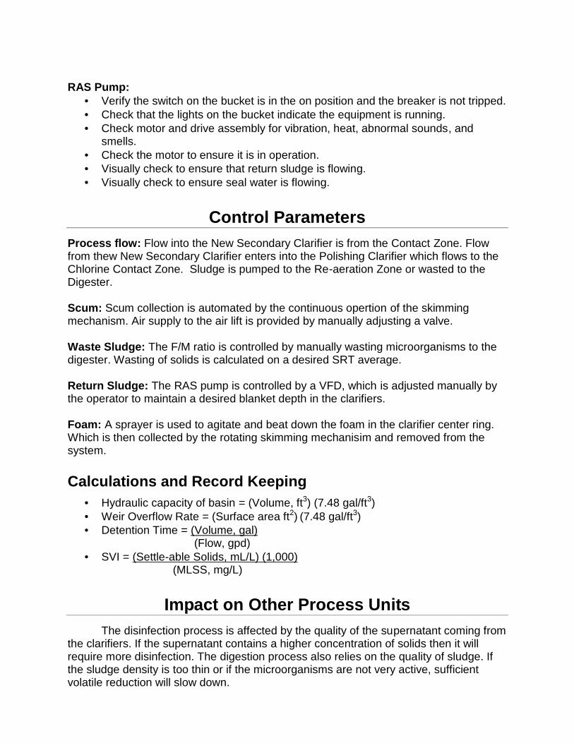
RAS Pump: Verify the switch on the bucket is in the on position and the breaker is not tripped. Check that the lights on the bucket indicate the equipment is running. Check motor and drive assembly for vibration, heat, abnormal sounds, and
smells. Check the motor to ensure it is in operation. Visually check to ensure that return sludge is flowing. Visually check to ensure seal water is flowing.
Control ParametersProcess flow: Flow into the New Secondary Clarifier is from the Contact Zone. Flowfrom thew New Secondary Clarifier enters into the Polishing Clarifier which flows to theChlorine Contact Zone. Sludge is pumped to the Re-aeration Zone or wasted to theDigester.
Scum: Scum collection is automated by the continuous opertion of the skimmingmechanism. Air supply to the air lift is provided by manually adjusting a valve.
Waste Sludge: The F/M ratio is controlled by manually wasting microorganisms to thedigester. Wasting of solids is calculated on a desired SRT average.
Return Sludge: The RAS pump is controlled by a VFD, which is adjusted manually bythe operator to maintain a desired blanket depth in the clarifiers.
Foam: A sprayer is used to agitate and beat down the foam in the clarifier center ring.Which is then collected by the rotating skimming mechanisim and removed from thesystem.
Calculations and Record Keeping Hydraulic capacity of basin = (Volume, ft3) (7.48 gal/ft3) Weir Overflow Rate = (Surface area ft2) (7.48 gal/ft3) Detention Time = (Volume, gal)
(Flow, gpd) SVI = (Settle-able Solids, mL/L) (1,000)
(MLSS, mg/L)
Impact on Other Process UnitsThe disinfection process is affected by the quality of the supernatant coming from
the clarifiers. If the supernatant contains a higher concentration of solids then it willrequire more disinfection. The digestion process also relies on the quality of sludge. Ifthe sludge density is too thin or if the microorganisms are not very active, sufficientvolatile reduction will slow down.
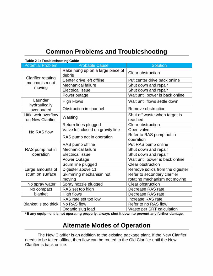
Common Problems and TroubleshootingTable 2-1: Troubleshooting GuidePotential Problem Probable Cause Solution
Clarifier rotatingmechanism not
moving
Rake hung up on a large piece ofdebris Clear obstruction
Center drive left offline Put center drive back onlineMechanical failure Shut down and repairElectrical issue Shut down and repairPower outage Wait until power is back online
Launderhydraulicallyoverloaded
High Flows Wait until flows settle down
Obstruction in channel Remove obstructionLittle weir overflowon New Clarifier Wasting Shut off waste when target is
reached
No RAS flow
Return lines plugged Clear obstructionValve left closed on gravity line Open valve
RAS pump not in operation Refer to RAS pump not inoperation
RAS pump not inoperation
RAS pump offline Put RAS pump onlineMechanical failure Shut down and repairElectrical issue Shut down and repairPower Outage Wait until power is back online
Large amounts ofscum on surface
Scum line plugged Clear obstructionDigester above 11’ Remove solids from the digesterSkimming mechanism notmoving
Refer to secondary clarifierrotating mechanism not moving
No spray water Spray nozzle plugged Clear obstructionNo compact
blanketRAS set too high Decrease RAS rateHigh flows Decrease RAS rate
Blanket is too thickRAS rate set too low Increase RAS rateNo RAS flow Refer to no RAS flowOrganic slug load Waste per SRT calculation
* If any equipment is not operating properly, always shut it down to prevent any further damage.
Alternate Modes of OperationThe New Clarifier is an addition to the existing package plant. If the New Clarifier
needs to be taken offline, then flow can be routed to the Old Clarifier until the NewClarifier is back online.
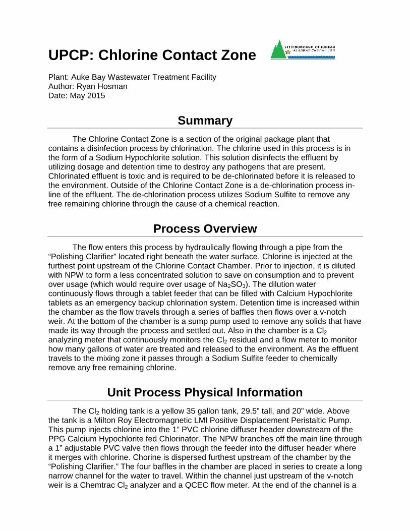
UPCP: Chlorine Contact ZonePlant: Auke Bay Wastewater Treatment FacilityAuthor: Ryan HosmanDate: May 2015
SummaryThe Chlorine Contact Zone is a section of the original package plant that
contains a disinfection process by chlorination. The chlorine used in this process is inthe form of a Sodium Hypochlorite solution. This solution disinfects the effluent byutilizing dosage and detention time to destroy any pathogens that are present.Chlorinated effluent is toxic and is required to be de-chlorinated before it is released tothe environment. Outside of the Chlorine Contact Zone is a de-chlorination process in-line of the effluent. The de-chlorination process utilizes Sodium Sulfite to remove anyfree remaining chlorine through the cause of a chemical reaction.
Process OverviewThe flow enters this process by hydraulically flowing through a pipe from the
“Polishing Clarifier” located right beneath the water surface. Chlorine is injected at thefurthest point upstream of the Chlorine Contact Chamber. Prior to injection, it is dilutedwith NPW to form a less concentrated solution to save on consumption and to preventover usage (which would require over usage of Na2SO3). The dilution watercontinuously flows through a tablet feeder that can be filled with Calcium Hypochloritetablets as an emergency backup chlorination system. Detention time is increased withinthe chamber as the flow travels through a series of baffles then flows over a v-notchweir. At the bottom of the chamber is a sump pump used to remove any solids that havemade its way through the process and settled out. Also in the chamber is a Cl2analyzing meter that continuously monitors the Cl2 residual and a flow meter to monitorhow many gallons of water are treated and released to the environment. As the effluenttravels to the mixing zone it passes through a Sodium Sulfite feeder to chemicallyremove any free remaining chlorine.
Unit Process Physical InformationThe Cl2 holding tank is a yellow 35 gallon tank, 29.5” tall, and 20” wide. Above
the tank is a Milton Roy Electromagnetic LMI Positive Displacement Peristaltic Pump.This pump injects chlorine into the 1” PVC chlorine diffuser header downstream of thePPG Calcium Hypochlorite fed Chlorinator. The NPW branches off the main line througha 1” adjustable PVC valve then flows through the feeder into the diffuser header whereit merges with chlorine. Chorine is dispersed furthest upstream of the chamber by the“Polishing Clarifier.” The four baffles in the chamber are placed in series to create a longnarrow channel for the water to travel. Within the channel just upstream of the v-notchweir is a Chemtrac Cl2 analyzer and a QCEC flow meter. At the end of the channel is a
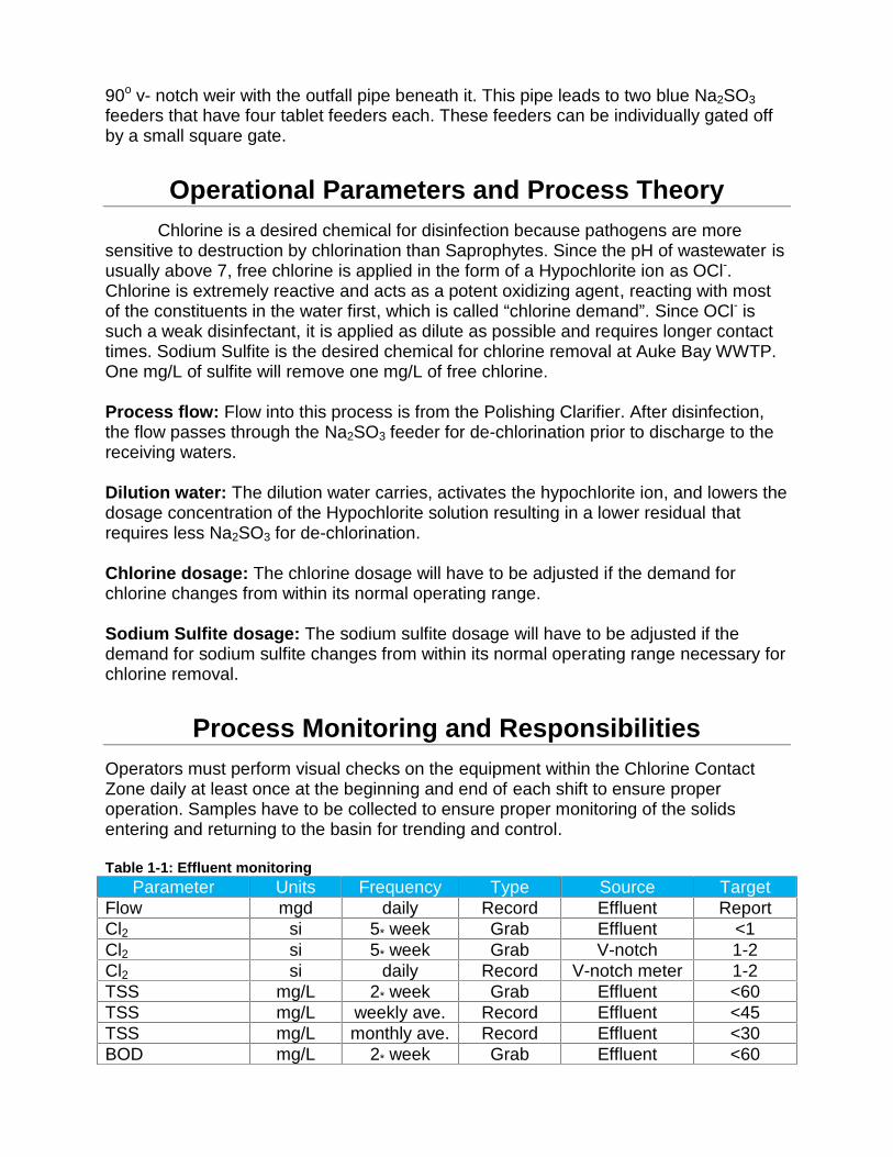
90o v- notch weir with the outfall pipe beneath it. This pipe leads to two blue Na2SO3feeders that have four tablet feeders each. These feeders can be individually gated offby a small square gate.
Operational Parameters and Process TheoryChlorine is a desired chemical for disinfection because pathogens are more
sensitive to destruction by chlorination than Saprophytes. Since the pH of wastewater isusually above 7, free chlorine is applied in the form of a Hypochlorite ion as OCl-.Chlorine is extremely reactive and acts as a potent oxidizing agent, reacting with mostof the constituents in the water first, which is called “chlorine demand”. Since OCl- issuch a weak disinfectant, it is applied as dilute as possible and requires longer contacttimes. Sodium Sulfite is the desired chemical for chlorine removal at Auke Bay WWTP.One mg/L of sulfite will remove one mg/L of free chlorine.
Process flow: Flow into this process is from the Polishing Clarifier. After disinfection,the flow passes through the Na2SO3 feeder for de-chlorination prior to discharge to thereceiving waters.
Dilution water: The dilution water carries, activates the hypochlorite ion, and lowers thedosage concentration of the Hypochlorite solution resulting in a lower residual thatrequires less Na2SO3 for de-chlorination.
Chlorine dosage: The chlorine dosage will have to be adjusted if the demand forchlorine changes from within its normal operating range.
Sodium Sulfite dosage: The sodium sulfite dosage will have to be adjusted if thedemand for sodium sulfite changes from within its normal operating range necessary forchlorine removal.
Process Monitoring and ResponsibilitiesOperators must perform visual checks on the equipment within the Chlorine ContactZone daily at least once at the beginning and end of each shift to ensure properoperation. Samples have to be collected to ensure proper monitoring of the solidsentering and returning to the basin for trending and control.
Table 1-1: Effluent monitoringParameter Units Frequency Type Source Target
Flow mgd daily Record Effluent ReportCl2 si 5* week Grab Effluent <1Cl2 si 5* week Grab V-notch 1-2Cl2 si daily Record V-notch meter 1-2TSS mg/L 2* week Grab Effluent <60TSS mg/L weekly ave. Record Effluent <45TSS mg/L monthly ave. Record Effluent <30BOD mg/L 2* week Grab Effluent <60
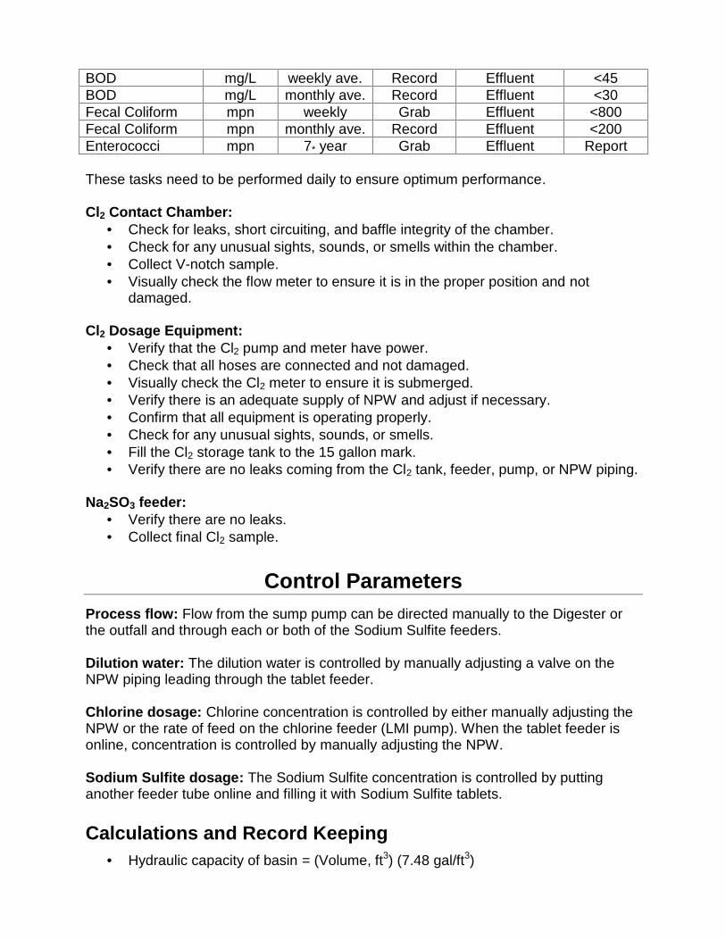
BOD mg/L weekly ave. Record Effluent <45BOD mg/L monthly ave. Record Effluent <30Fecal Coliform mpn weekly Grab Effluent <800Fecal Coliform mpn monthly ave. Record Effluent <200Enterococci mpn 7* year Grab Effluent Report
These tasks need to be performed daily to ensure optimum performance.
Cl2 Contact Chamber: Check for leaks, short circuiting, and baffle integrity of the chamber. Check for any unusual sights, sounds, or smells within the chamber. Collect V-notch sample. Visually check the flow meter to ensure it is in the proper position and not
damaged.
Cl2 Dosage Equipment: Verify that the Cl2 pump and meter have power. Check that all hoses are connected and not damaged. Visually check the Cl2 meter to ensure it is submerged. Verify there is an adequate supply of NPW and adjust if necessary. Confirm that all equipment is operating properly. Check for any unusual sights, sounds, or smells. Fill the Cl2 storage tank to the 15 gallon mark. Verify there are no leaks coming from the Cl2 tank, feeder, pump, or NPW piping.
Na2SO3 feeder: Verify there are no leaks. Collect final Cl2 sample.
Control ParametersProcess flow: Flow from the sump pump can be directed manually to the Digester orthe outfall and through each or both of the Sodium Sulfite feeders.
Dilution water: The dilution water is controlled by manually adjusting a valve on theNPW piping leading through the tablet feeder.
Chlorine dosage: Chlorine concentration is controlled by either manually adjusting theNPW or the rate of feed on the chlorine feeder (LMI pump). When the tablet feeder isonline, concentration is controlled by manually adjusting the NPW.
Sodium Sulfite dosage: The Sodium Sulfite concentration is controlled by puttinganother feeder tube online and filling it with Sodium Sulfite tablets.
Calculations and Record Keeping Hydraulic capacity of basin = (Volume, ft3) (7.48 gal/ft3)
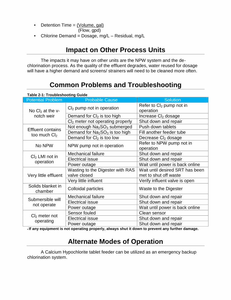
Detention Time = (Volume, gal)(Flow, gpd)
Chlorine Demand = Dosage, mg/L – Residual, mg/L
Impact on Other Process UnitsThe impacts it may have on other units are the NPW system and the de-
chlorination process. As the quality of the effluent degrades, water reused for dosagewill have a higher demand and screens/ strainers will need to be cleaned more often.
Common Problems and TroubleshootingTable 2-1: Troubleshooting GuidePotential Problem Probable Cause Solution
No Cl2 at the v-notch weir
Cl2 pump not in operation Refer to Cl2 pump not inoperation
Demand for Cl2 is too high Increase Cl2 dosageCl2 meter not operating properly Shut down and repair
Effluent containstoo much Cl2
Not enough Na2SO3 submerged Push down tabletsDemand for Na2SO3 is too high Fill another feeder tubeDemand for Cl2 is too low Decrease Cl2 dosage
No NPW NPW pump not in operation Refer to NPW pump not inoperation
Cl2 LMI not inoperation
Mechanical failure Shut down and repairElectrical issue Shut down and repairPower outage Wait until power is back online
Very little effluentWasting to the Digester with RASvalve closed
Wait until desired SRT has beenmet to shut off waste
Very little influent Verify influent valve is openSolids blanket in
chamber Colloidal particles Waste to the Digester
Submersible willnot operate
Mechanical failure Shut down and repairElectrical issue Shut down and repairPower outage Wait until power is back online
Cl2 meter notoperating
Sensor fouled Clean sensorElectrical issue Shut down and repairPower outage Shut down and repair
* If any equipment is not operating properly, always shut it down to prevent any further damage.
Alternate Modes of OperationA Calcium Hypochlorite tablet feeder can be utilized as an emergency backup
chlorination system.
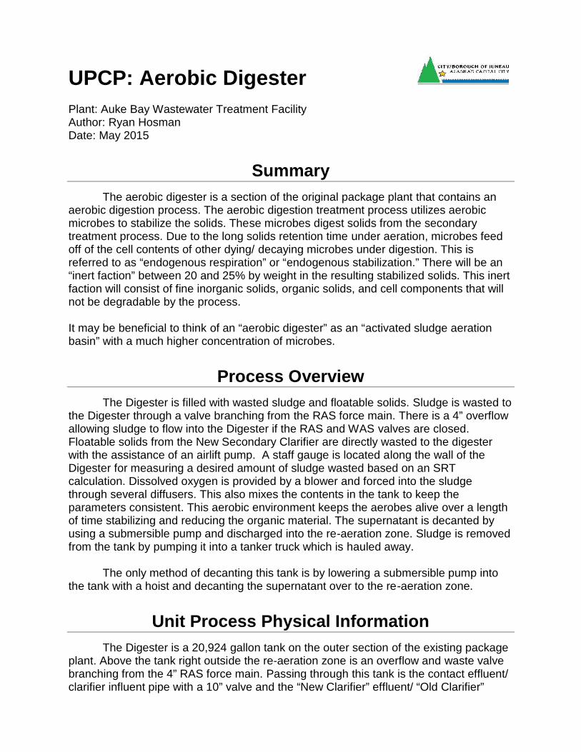
UPCP: Aerobic DigesterPlant: Auke Bay Wastewater Treatment FacilityAuthor: Ryan HosmanDate: May 2015
SummaryThe aerobic digester is a section of the original package plant that contains an
aerobic digestion process. The aerobic digestion treatment process utilizes aerobicmicrobes to stabilize the solids. These microbes digest solids from the secondarytreatment process. Due to the long solids retention time under aeration, microbes feedoff of the cell contents of other dying/ decaying microbes under digestion. This isreferred to as “endogenous respiration” or “endogenous stabilization.” There will be an“inert faction” between 20 and 25% by weight in the resulting stabilized solids. This inertfaction will consist of fine inorganic solids, organic solids, and cell components that willnot be degradable by the process.
It may be beneficial to think of an “aerobic digester” as an “activated sludge aerationbasin” with a much higher concentration of microbes.
Process OverviewThe Digester is filled with wasted sludge and floatable solids. Sludge is wasted to
the Digester through a valve branching from the RAS force main. There is a 4” overflowallowing sludge to flow into the Digester if the RAS and WAS valves are closed.Floatable solids from the New Secondary Clarifier are directly wasted to the digesterwith the assistance of an airlift pump. A staff gauge is located along the wall of theDigester for measuring a desired amount of sludge wasted based on an SRTcalculation. Dissolved oxygen is provided by a blower and forced into the sludgethrough several diffusers. This also mixes the contents in the tank to keep theparameters consistent. This aerobic environment keeps the aerobes alive over a lengthof time stabilizing and reducing the organic material. The supernatant is decanted byusing a submersible pump and discharged into the re-aeration zone. Sludge is removedfrom the tank by pumping it into a tanker truck which is hauled away.
The only method of decanting this tank is by lowering a submersible pump intothe tank with a hoist and decanting the supernatant over to the re-aeration zone.
Unit Process Physical InformationThe Digester is a 20,924 gallon tank on the outer section of the existing package
plant. Above the tank right outside the re-aeration zone is an overflow and waste valvebranching from the 4” RAS force main. Passing through this tank is the contact effluent/clarifier influent pipe with a 10” valve and the “New Clarifier” effluent/ “Old Clarifier”
influent pipe with a 10” valve. Located in the tank along the outer wall is a 3” air liftwhere the scum line ends. Along the inner wall is a 16.5’ staff gauge for levelmeasurement. There are 3 diffuser headers with 12 fine bubble diffusers.
Operational Parameters and Process TheoryAerobes need DO to thrive and a fresh source of food to reproduce. DO is
provided to keep them alive but their source of food is restricted. This throws the F/Mratio out of balance over a period of time causing the aerobes to oxidize their owncellular mass. Some microorganisms break down releasing their cellular matter whilethe remaining aerobes use it as a food source continuing to break it down. This foodsource continually diminishes resulting in further break down. While the aerobesconsume organic cellular matter they produce carbon dioxide and result in a stableoxidized sludge. Cellular mass is mostly bound water which is released when organicmatter is broken down improving sludge dewater-ability.
Process flow: The sludge process flow is directed to the digester when it is necessaryto waste or if both the RAS valve to the Re-aeration Zone and waste valves to theDigester are closed.
Level Control: The level is controlled by the quantity of sludge wasted based on adesired SRT and how many loads are removed by a sludge hauling truck “(tanker)”.
DO: Dissolved oxygen is maintained throughout the tank to keep the aerobes alive forproper breakdown.
TSS Concentration: Holding a thicker sludge allows the digester to maintain a longerdetention time resulting in a higher inert faction.
Supernatant: Supernatant takes up unnecessary space in the digester and reducesavailable detention time.
Process Monitoring and ResponsibilitiesOperators must perform visual checks on the Digester equipment daily at least once atthe beginning and end of each shift to ensure proper operation.
These tasks need to be performed daily to ensure optimum performance.
Digester: Check for leaks or anything that will compromise the integrity of the tank. Identify foam type if any to determine the condition of the sludge. Any unusual sights, sounds, or smells within the basin. Check the sludge for consistent aeration, no boiling spots. Visually check the level in the Digester.
Aerators:
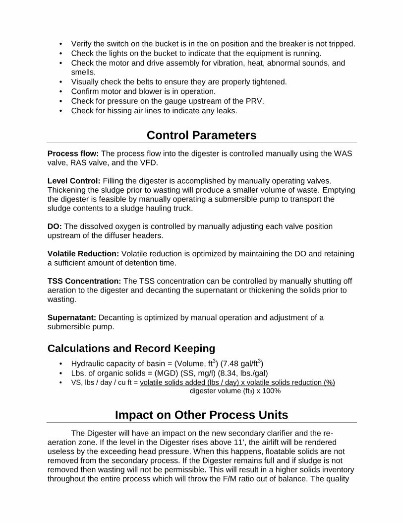
Verify the switch on the bucket is in the on position and the breaker is not tripped. Check the lights on the bucket to indicate that the equipment is running. Check the motor and drive assembly for vibration, heat, abnormal sounds, and
smells. Visually check the belts to ensure they are properly tightened. Confirm motor and blower is in operation. Check for pressure on the gauge upstream of the PRV. Check for hissing air lines to indicate any leaks.
Control ParametersProcess flow: The process flow into the digester is controlled manually using the WASvalve, RAS valve, and the VFD.
Level Control: Filling the digester is accomplished by manually operating valves.Thickening the sludge prior to wasting will produce a smaller volume of waste. Emptyingthe digester is feasible by manually operating a submersible pump to transport thesludge contents to a sludge hauling truck.
DO: The dissolved oxygen is controlled by manually adjusting each valve positionupstream of the diffuser headers.
Volatile Reduction: Volatile reduction is optimized by maintaining the DO and retaininga sufficient amount of detention time.
TSS Concentration: The TSS concentration can be controlled by manually shutting offaeration to the digester and decanting the supernatant or thickening the solids prior towasting.
Supernatant: Decanting is optimized by manual operation and adjustment of asubmersible pump.
Calculations and Record Keeping Hydraulic capacity of basin = (Volume, ft3) (7.48 gal/ft3) Lbs. of organic solids = (MGD) (SS, mg/l) (8.34, lbs./gal) VS, lbs / day / cu ft = volatile solids added (lbs / day) x volatile solids reduction (%)
digester volume (ft3) x 100%
Impact on Other Process UnitsThe Digester will have an impact on the new secondary clarifier and the re-
aeration zone. If the level in the Digester rises above 11’, the airlift will be rendereduseless by the exceeding head pressure. When this happens, floatable solids are notremoved from the secondary process. If the Digester remains full and if sludge is notremoved then wasting will not be permissible. This will result in a higher solids inventorythroughout the entire process which will throw the F/M ratio out of balance. The quality
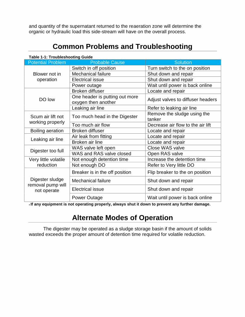
and quantity of the supernatant returned to the reaeration zone will determine theorganic or hydraulic load this side-stream will have on the overall process.
Common Problems and TroubleshootingTable 1-1: Troubleshooting GuidePotential Problem Probable Cause Solution
Blower not inoperation
Switch in off position Turn switch to the on positionMechanical failure Shut down and repairElectrical issue Shut down and repairPower outage Wait until power is back online
DO low
Broken diffuser Locate and repairOne header is putting out moreoxygen then another Adjust valves to diffuser headers
Leaking air line Refer to leaking air line
Scum air lift notworking properly
Too much head in the Digester Remove the sludge using thetanker
Too much air flow Decrease air flow to the air liftBoiling aeration Broken diffuser Locate and repair
Leaking air line Air leak from fitting Locate and repairBroken air line Locate and repair
Digester too full WAS valve left open Close WAS valveWAS and RAS valve closed Open RAS valve
Very little volatilereduction
Not enough detention time Increase the detention timeNot enough DO Refer to Very little DO
Digester sludgeremoval pump will
not operate
Breaker is in the off position Flip breaker to the on position
Mechanical failure Shut down and repair
Electrical issue Shut down and repair
Power Outage Wait until power is back online* If any equipment is not operating properly, always shut it down to prevent any further damage.
Alternate Modes of OperationThe digester may be operated as a sludge storage basin if the amount of solids
wasted exceeds the proper amount of detention time required for volatile reduction.
UPCP: Reaeration zonePlant: Auke Bay Wastewater Treatment FacilityAuthor: Ryan HosmanDate: May 2015
SummaryThe reaeration zone is another critical component of the biological treatment
process using oxygen consuming bacteria to absorb the carbonaceous materialadsorbed from the contact zone. Absorption is the taking in of a substance into the bodyof another. One of the main aspects involved in the reaeration zone of the contact-stabilization process is the generation of sludge. In any aeration system, where food inthe form of carbonaceous material is available, bacteria will start to multiply and thebuildup in the biomass contributes to the increase in the quantity of sludge. As theamount increases, it will finally reach equilibrium with the amount of food available andthe generation of new cells will be halted. Ridding the system or wasting of this excesssludge as it is referred to in the industry is carried out in order to control the generationof sludge and to remove dead microorganisms. This will ensure a balanced systemwhereby the new bacteria will have a chance to propagate and replace the aging ones.
Process OverviewThe nutrient rich bacteria in this process are directed to a basin through a RAS
pump. Once they enter the basin they are given dissolved oxygen and enough detentiontime to consume their adsorbed material. Once this carbonaceous material has beendigested the aerobes become eager to adsorb more. The dissolved oxygen is providedby forcing ambient oxygen into the water through the use of blowers and diffusers. Thelevel within the reaeration zone is hydraulically balanced with the contact zone. As RASis entering into the basin, sludge flows back into the contact zone thus reintroducing the“starved” activated sludge to the incoming food source and oxygen supply.
Unit Process Physical InformationThe reaeration Zone is a 12,985 gallon tank on the outside section of the
existing package plant. There are 4 diffuser headers with 12 diffusers on each header.This header is plumbed to a 26.5’ tubular tank underneath the catwalk supporting it fromeach side across the top of the package plant. This tank is plumbed to two positivedisplacement blowers with a Kunkle PRV on each blower. The blowers are belt drivenby a 15 HP Tatlung Co. motor and a 15 HP Emerson motor.
Operational Parameters and Process TheoryContained in this basin are massive microbiology colonies that are cultured from
the raw wastewater. The microorganisms chosen to be cultured in this process areaerobes. These aerobes are desirable because they do not normally produce foul odorsor harmful gases and they provide adequate treatment within a relatively short amounttime. They rely on the incoming food source and dissolved oxygen to survive andreproduce. It is very important that the microorganisms do not overpopulate or thedemand for food will be thrown out of balance. This is accomplished by removing anyexcessive microorganisms. The microbiology consists of bacterium, protozoa, rotifers,nematodes, and filamentous microorganisms. As fresh sludge is introduced to theenvironment it is considered young. This young sludge contains very little amoeboidwith mostly free- swimming ciliates and flagellates. This sludge is not desirable becauseit produces straggler floc. As the sludge ages, it becomes more desirable producinggood settling floc. This sludge contains more free- swimming and stalked ciliates with agood amount of flagellates. After the desirable range the sludge becomes too oldproducing pin floc which also does not settle well. In this sludge there are mostly rotiferswith not many other microorganisms left.
Process flow: The flow coming into the re-aeration zone is dependent on the RAS flowrate. The flow from the Re-aeration Zone back into the Contact Zone can be adjustedby adjusting the “reseed” valve.
DO: Dissolved oxygen is maintained throughout the tank to supply the aerobes withoxygen in order to perform adequate treatment.
Food/ Microorganism (F/M) Ratio: The operator has no control over the incoming foodsource but has control over the population of microorganisms. The F/M ratio is balancedby wasting concentrated sludge from the activated sludge process. This isaccomplished by valving RAS from the New Secondary Clarifier to the Digester insteadof the Reaeration Zone.
Process Monitoring and ResponsibilitiesOperators must perform visual checks on the equipment within the Reaeration Zonedaily at least once at the beginning and end of each shift to ensure proper operation.Samples have to be collected to ensure proper monitoring of the solids for calculating,trending, and control.
Table 1-1: Solids monitoringParameter Units Frequency Type Source Target
TSS mg/L 5* week Royce Grab Reaeration SS 4500-5000D.O. Mg/L 5* week Royce Grab Reaeration SS 1-3
These tasks need to be performed daily to ensure optimum performance.
Reaeration Zone Basin:
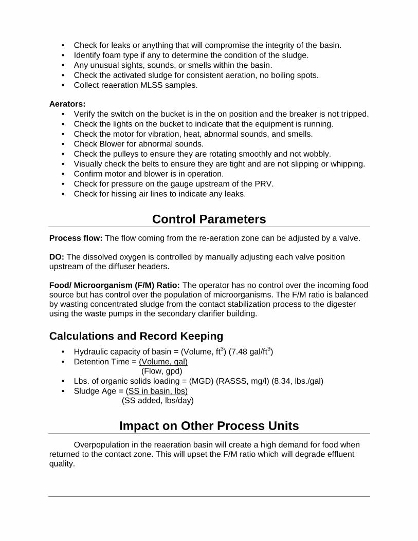
Check for leaks or anything that will compromise the integrity of the basin. Identify foam type if any to determine the condition of the sludge. Any unusual sights, sounds, or smells within the basin. Check the activated sludge for consistent aeration, no boiling spots. Collect reaeration MLSS samples.
Aerators: Verify the switch on the bucket is in the on position and the breaker is not tripped. Check the lights on the bucket to indicate that the equipment is running. Check the motor for vibration, heat, abnormal sounds, and smells. Check Blower for abnormal sounds. Check the pulleys to ensure they are rotating smoothly and not wobbly. Visually check the belts to ensure they are tight and are not slipping or whipping. Confirm motor and blower is in operation. Check for pressure on the gauge upstream of the PRV. Check for hissing air lines to indicate any leaks.
Control ParametersProcess flow: The flow coming from the re-aeration zone can be adjusted by a valve.
DO: The dissolved oxygen is controlled by manually adjusting each valve positionupstream of the diffuser headers.
Food/ Microorganism (F/M) Ratio: The operator has no control over the incoming foodsource but has control over the population of microorganisms. The F/M ratio is balancedby wasting concentrated sludge from the contact stabilization process to the digesterusing the waste pumps in the secondary clarifier building.
Calculations and Record Keeping Hydraulic capacity of basin = (Volume, ft3) (7.48 gal/ft3) Detention Time = (Volume, gal)
(Flow, gpd) Lbs. of organic solids loading = (MGD) (RASSS, mg/l) (8.34, lbs./gal) Sludge Age = (SS in basin, lbs)
(SS added, lbs/day)
Impact on Other Process UnitsOverpopulation in the reaeration basin will create a high demand for food when
returned to the contact zone. This will upset the F/M ratio which will degrade effluentquality.
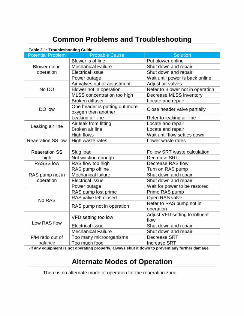
Common Problems and TroubleshootingTable 2-1: Troubleshooting GuidePotential Problem Probable Cause Solution
Blower not inoperation
Blower is offline Put blower onlineMechanical Failure Shut down and repairElectrical issue Shut down and repairPower outage Wait until power is back online
No DOAir valves out of adjustment Adjust air valvesBlower not in operation Refer to Blower not in operationMLSS concentration too high Decrease MLSS inventory
DO low
Broken diffuser Locate and repairOne header is putting out moreoxygen then another Close header valve partially
Leaking air line Refer to leaking air line
Leaking air line Air leak from fitting Locate and repairBroken air line Locate and repair
Reaeration SS lowHigh flows Wait until flow settles downHigh waste rates Lower waste rates
Reaeration SShigh
Slug load Follow SRT waste calculationNot wasting enough Decrease SRT
RASSS low RAS flow too high Decrease RAS flow
RAS pump not inoperation
RAS pump offline Turn on RAS pumpMechanical failure Shut down and repairElectrical issue Shut down and repairPower outage Wait for power to be restored
No RAS
RAS pump lost prime Prime RAS pumpRAS valve left closed Open RAS valve
RAS pump not in operation Refer to RAS pump not inoperation
Low RAS flowVFD setting too low Adjust VFD setting to influent
flowElectrical issue Shut down and repairMechanical Failure Shut down and repair
F/M ratio out ofbalance
Too many microorganisms Decrease SRTToo much food Increase SRT
* If any equipment is not operating properly, always shut it down to prevent any further damage.
Alternate Modes of OperationThere is no alternate mode of operation for the reaeration zone.
UPCP: Non-Potable Water SystemPlant: Auke Bay Wastewater Treatment FacilityAuthor: Ryan HosmanDate: May 2015
SummaryThe Auke Bay Wastewater Treatment Facility uses large quantities of water for
chemical dosing and pump seal lubrication purposes. The NPW System is designed toreclaim and distribute treated effluent from the disinfection process after it has beenthrough pre- screening, grit removal, aeration, sedimentation, and clarification tonumerous locations throughout the facility.
Process OverviewA non-potable water pump draws water out of the effluent channel which is
filtered by a strainer. It is pumped to a pneumatic tank which contains an air pocket thatis compressed inside the tank to increase the NPW pressure throughout the facility. It isthen distributed to the RAS pump and chlorine injection point.
Unit Process Physical InformationThe water is drawn out of the effluent channel by a 0.5 HP Baldor powered
centrifugal pump underneath the first set of stairs by the blue pneumatic tank. Thepiping is an inch in diameter with a strainer on the end of the suction line submerged inthe Chlorine Contact Chamber. Upstream of the impeller is a tee connection for apotable water line. The pneumatic tank is 3’ tall, 1.5’ in diameter blue pneumatic tank.
Operational Parameters and Process TheoryDosage and lubrication requires large quantities of water to continually dilute
chemicals and lubricate pump seals. Because the quantity is so large, it is necessary toutilize the effluent as a reusable water source. City water is not desirable due to the costand quantity it would require to operate equipment or provide for process.
Emergency Backup Water: If the NPW pump fails then chemical dosage cannot becontrolled easily and the RAS pump seal would burn up. Provisions are in place for thefeeding of W-2 water into the piping system.
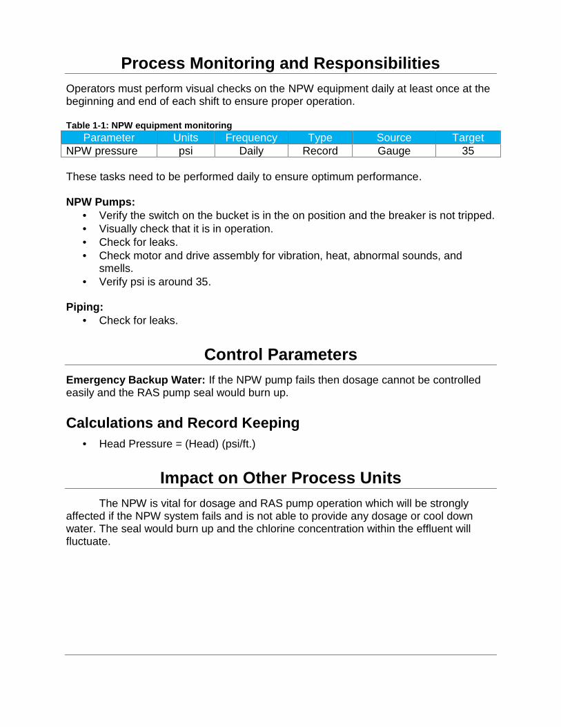
Process Monitoring and ResponsibilitiesOperators must perform visual checks on the NPW equipment daily at least once at thebeginning and end of each shift to ensure proper operation.
Table 1-1: NPW equipment monitoringParameter Units Frequency Type Source Target
NPW pressure psi Daily Record Gauge 35
These tasks need to be performed daily to ensure optimum performance.
NPW Pumps: Verify the switch on the bucket is in the on position and the breaker is not tripped. Visually check that it is in operation. Check for leaks. Check motor and drive assembly for vibration, heat, abnormal sounds, and
smells. Verify psi is around 35.
Piping: Check for leaks.
Control ParametersEmergency Backup Water: If the NPW pump fails then dosage cannot be controlledeasily and the RAS pump seal would burn up.
Calculations and Record Keeping Head Pressure = (Head) (psi/ft.)
Impact on Other Process UnitsThe NPW is vital for dosage and RAS pump operation which will be strongly
affected if the NPW system fails and is not able to provide any dosage or cool downwater. The seal would burn up and the chlorine concentration within the effluent willfluctuate.
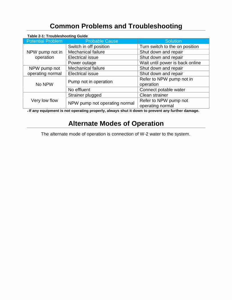
Common Problems and TroubleshootingTable 2-1: Troubleshooting GuidePotential Problem Probable Cause Solution
NPW pump not inoperation
Switch in off position Turn switch to the on positionMechanical failure Shut down and repairElectrical issue Shut down and repairPower outage Wait until power is back online
NPW pump notoperating normal
Mechanical failure Shut down and repairElectrical issue Shut down and repair
No NPW Pump not in operation Refer to NPW pump not inoperation
No effluent Connect potable water
Very low flowStrainer plugged Clean strainer
NPW pump not operating normal Refer to NPW pump notoperating normal
* If any equipment is not operating properly, always shut it down to prevent any further damage.
Alternate Modes of OperationThe alternate mode of operation is connection of W-2 water to the system.
ABTP Operations and Maintenance Plan
Appendix CABTP As-Built Drawing
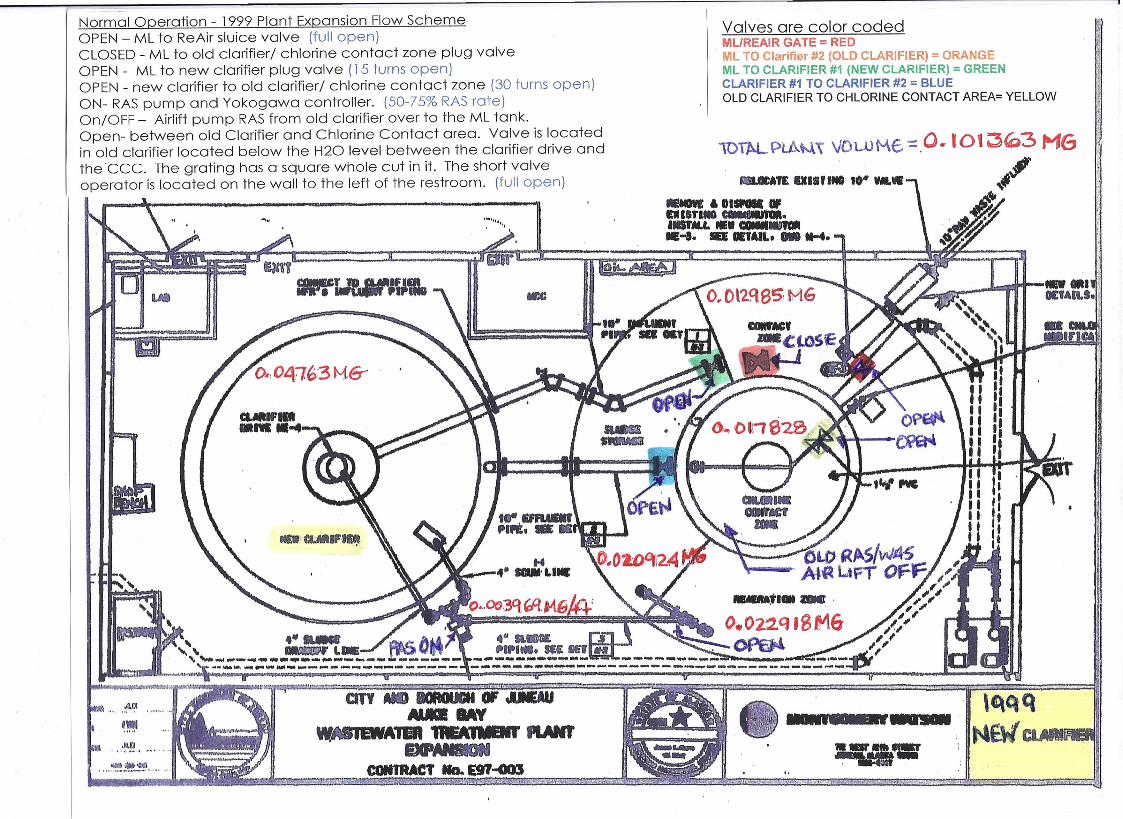
1
Normal Operation - 1999Plant Expansion Flow SchemeOPEN- ML to ReAir sluice valve (full open)CLOSED- ML to old clarifier! chlorine contact zone plug valveOPEN- ML to new clarifier plug valve (15 turns open)OPEN- new clarifier to old clarifier! chlorine contact zone (30 turns open)ON- RASpump and Yokogawa controller. (50-75%RASrate)On!OFF - Airlift pump RASfrom old clarifier over to the ML tank.Open- between old Clarifier and Chlorine Contact area. Valve is locatedin old clarifier located below the H20 level between the clarifier drive andtheCCC. The grating has a square whole cut in it. The short valveoperator is located on the wall to the left of the restroom. (full open)
Valves are color codedMUREAIR GATE = REDML TO Clarifier #2 (OLD CLARIFIER) = ORANGEML TO CLARIFIER #1 (NEW CLARIFIER) = GREENCLARIFIER #1 TO CLARIFIER #2 = BLUEOLD CLARIFIER TO CHLORINE CONTACT AREA= YELLOW
AWltA1E IXISUMI 10· , •.•
•••••• 'DI••••hIST••• CCIIIM8 ••••."" •......•....•• -1. _ DEtAIL, _ ••••••
.." ..•.,' .."
or~nIIIfI.RMIDI..
A!·) .•••.,. ••:t:"'· .•·~~-~M'I. Z -'''( •. *TIrl3'Yi':rI"i'!ir'iJ!I7i"U;'~,iCi;1o-
CITY MD IIOAOI8I " aauMICI MY
W.ASIEWATER 1'MA .•.•••. IUNI'IDCPAJaON
CONTRACT Ma.. E97-G03e~d~1mEiP.i!v:vml';'~~!iii5&¥.z;H t.46gr;;,~ ir;;t~"WSY§-l!~,*~
,qqqN6W~11
" ....• :11Jll
U -.- .,..-UU.*1lfLi" .~~ .
.•.. ~.~'IOIl."' ..»ot.i iF1 _t:A-. ...?-,q.~~;:;;t;i.•.u .•.x· !"",,-y;~ -,~-\'~·~_'~:-:-l;;.'