Embed Size (px)
Citation preview
TPW-D-0012-B
1
Operational Safety Procedure (OSP)
For The
High Voltage Pulsed Power System
At the
Texas Center for High Intensity Laser Science
Texas Center for High Intensity Laser Science
Dept. of Physics, The University of Texas at Austin
Austin, TX 78712
Document Number TPW-D-0012-B
TPW-D-0012-B
2
1. Introduction/Purpose This document establishes policy and procedure to control access to areas of this
facility where electrical hazards exist from exposed electrical conductors or high voltage
capacitors used with pulsed power. This Operational Safety Procedure (OSP) document
also defines specific access procedures and actions required by personnel, students,
experimenters and visitors in order to access the pulsed power capacitor room and or
catwalks.
The Facility Manager, Mikael Martinez (471-5648) maintains the master copy of
this document which is kept on file for reference.
2. Scope
This Safety Procedure shall be used by everyone; all Laser System operators,
RI’s, and Experimental Personnel must read and sign this document before access to the
pulsed power room or catwalks can be granted. Signature and document revision
management can be found on the last page of this document.
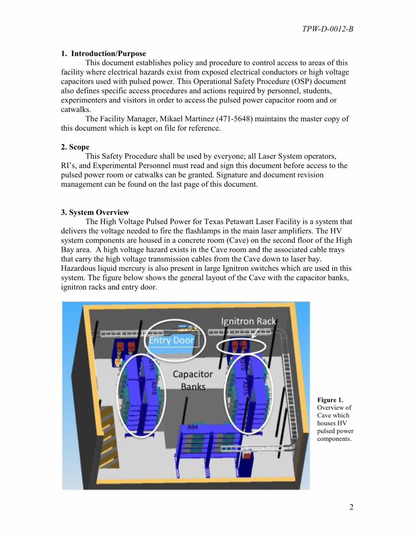
3. System Overview The High Voltage Pulsed Power for Texas Petawatt Laser Facility is a system that
delivers the voltage needed to fire the flashlamps in the main laser amplifiers. The HV
system components are housed in a concrete room (Cave) on the second floor of the High
Bay area. A high voltage hazard exists in the Cave room and the associated cable trays
that carry the high voltage transmission cables from the Cave down to laser bay.
Hazardous liquid mercury is also present in large Ignitron switches which are used in this
system. The figure below shows the general layout of the Cave with the capacitor banks,
ignitron racks and entry door.
Figure 1.
Overview of
Cave which
houses HV
pulsed power
components.
TPW-D-0012-B
3
4. Descriptions of Pulsed Power Room Hazards
Eye Hazard: The laser system is a Class IV laser and can cause severe
eye damage, skin burns and ignite flammable materials. This hazard is
present when accessing the Cave when laser light is present in the Target
Area.
High Voltage Hazard: All of the electrical apparatus used in the Cave
presents a lethal electric shock hazard.
Hazardous Materials: Ignitron switches contain liquid mercury. The
large capacitors contain transformer oil. Under normal conditions the
mercury and the transformer oil is safely sealed inside their respective
housings, but can pose a hazard if leaked.
5. Duties of the Responsible Individuals (PRI) and (RI)
The Pulsed Power system is maintained by the primary responsible individual
(PRI) who oversees the normal operation of the high voltage equipment and apparatus
used in the pulsed power Cave. The RI is a backup individual who is authorized to
change the status of the Cave to SAFE mode for general access (i.e. tours and limited
work). The RI is also authorized to change the status to ENERGIZED mode for full
system laser operation. An RI can also issue stop work orders or deny access to anyone if
it is determined that safety is or will be compromised. Only the PRI can perform repair
work, adjustments, testing, and or modifications to the high voltage apparatus in the
Cave.
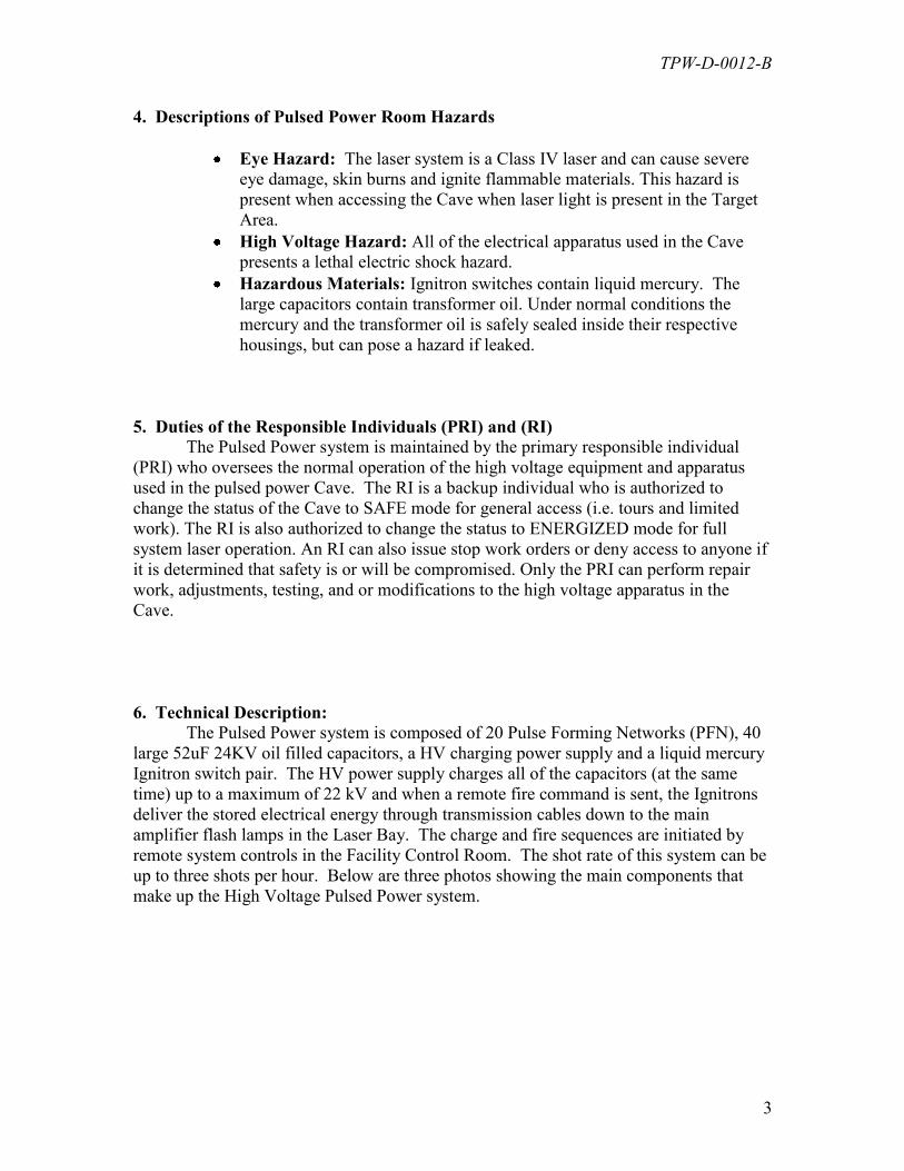
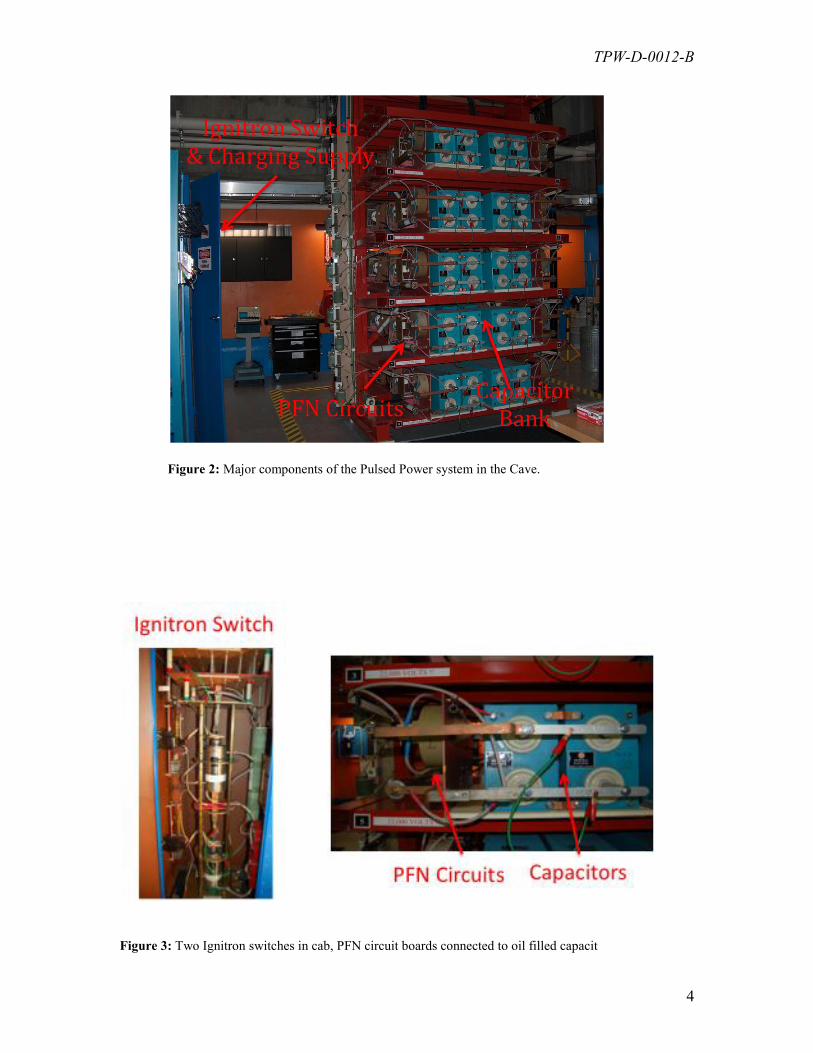
6. Technical Description:
The Pulsed Power system is composed of 20 Pulse Forming Networks (PFN), 40
large 52uF 24KV oil filled capacitors, a HV charging power supply and a liquid mercury
Ignitron switch pair. The HV power supply charges all of the capacitors (at the same
time) up to a maximum of 22 kV and when a remote fire command is sent, the Ignitrons
deliver the stored electrical energy through transmission cables down to the main
amplifier flash lamps in the Laser Bay. The charge and fire sequences are initiated by
remote system controls in the Facility Control Room. The shot rate of this system can be
up to three shots per hour. Below are three photos showing the main components that
make up the High Voltage Pulsed Power system.
TPW-D-0012-B
4
Figure 2: Major components of the Pulsed Power system in the Cave.
Figure 3: Two Ignitron switches in cab, PFN circuit boards connected to oil filled capacit
TPW-D-0012-B
5
7. Modes of Operation:
The Pulsed Power System will be set into one of the three states below.
SAFE: (ALL CLEAR): This mode means that the HV system (ignitrons, capacitors &
transmission cables) are discharged and shorted out, primary power is locked out at the
mains circuit breaker and room access is safe. In this state, authorized visitors and
technical staff are allowed access to the cave. The RI will authorize access or escort at
his discretion.
RESTRICTED ACCESS: This is an intermediate state or mode where the high voltage
charging power supply circuit breaker is shut off and locked out, however, the capacitors
and ignitrons are not shorted out. Although the charge sequence cannot be initiated, a
high voltage hazard still exists. In this case, the Cave doors will be padlocked and LCD
interlock status panel screens “ISP” will display “Restricted Access” The scrolling
message display directly above the Cave entry doors will read “NOT SAFE
AUTHORIZED PERSONNEL ONLY”.
NO ACCESS: This is the state or mode where all system components are live and
charge & fire sequences can be initiated. The Cave doors will be padlocked. The LCD
interlock status panels will display “NO ENTRY” and the scrolling message display will
read “PP ENERGIZED NO ENTRY!!” When all facility interlocks are activated and
the control point has Pulsed Power enabled, red light beacons in the facility will flash
indicating the charge and fire cycle can start at any moment. Triggering any of the
interlocks will abort the charge cycle discharge the stored energy in the capacitors into
the dump-rods resistors network. This WILL NOT lead to a safe mode. Remaining
charges on cables and other components can still pose a lethal hazard. Do not access the
catwalk over the roof of the Laser Bay.
TPW-D-0012-B
6
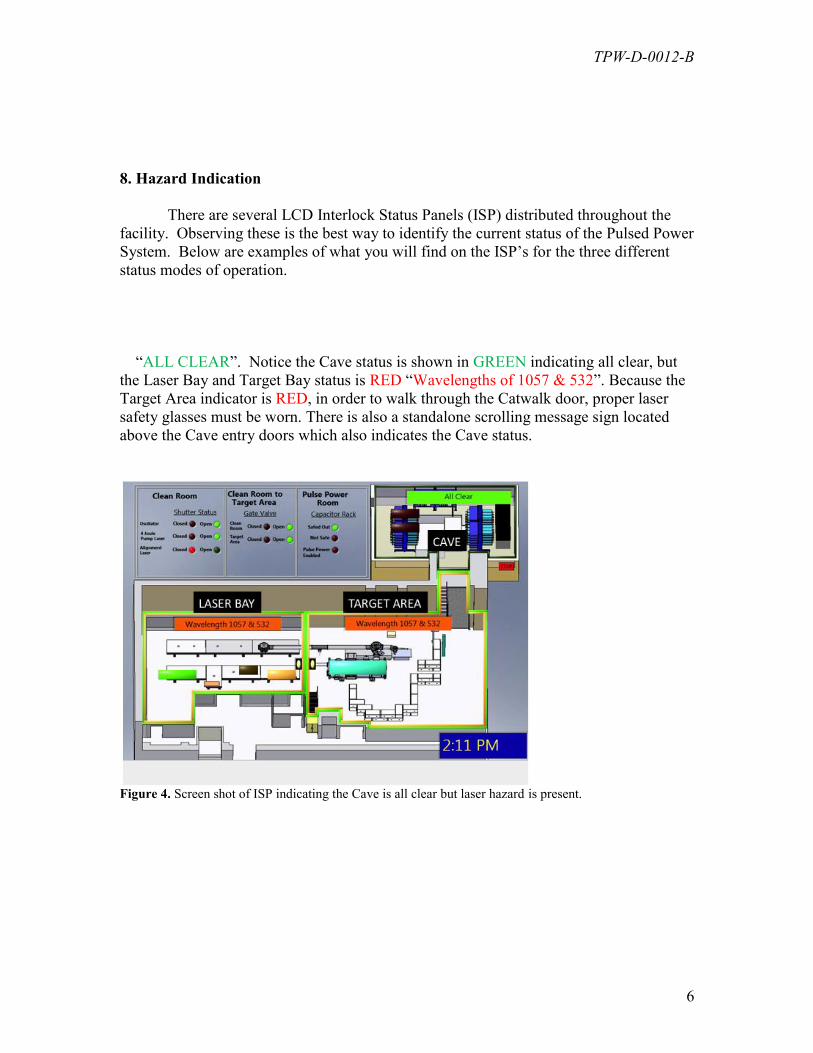
8. Hazard Indication
There are several LCD Interlock Status Panels (ISP) distributed throughout the
facility. Observing these is the best way to identify the current status of the Pulsed Power
System. Below are examples of what you will find on the ISP’s for the three different
status modes of operation.
“ALL CLEAR”. Notice the Cave status is shown in GREEN indicating all clear, but
the Laser Bay and Target Bay status is RED “Wavelengths of 1057 & 532”. Because the
Target Area indicator is RED, in order to walk through the Catwalk door, proper laser
safety glasses must be worn. There is also a standalone scrolling message sign located
above the Cave entry doors which also indicates the Cave status.
Figure 4. Screen shot of ISP indicating the Cave is all clear but laser hazard is present.
TPW-D-0012-B
7
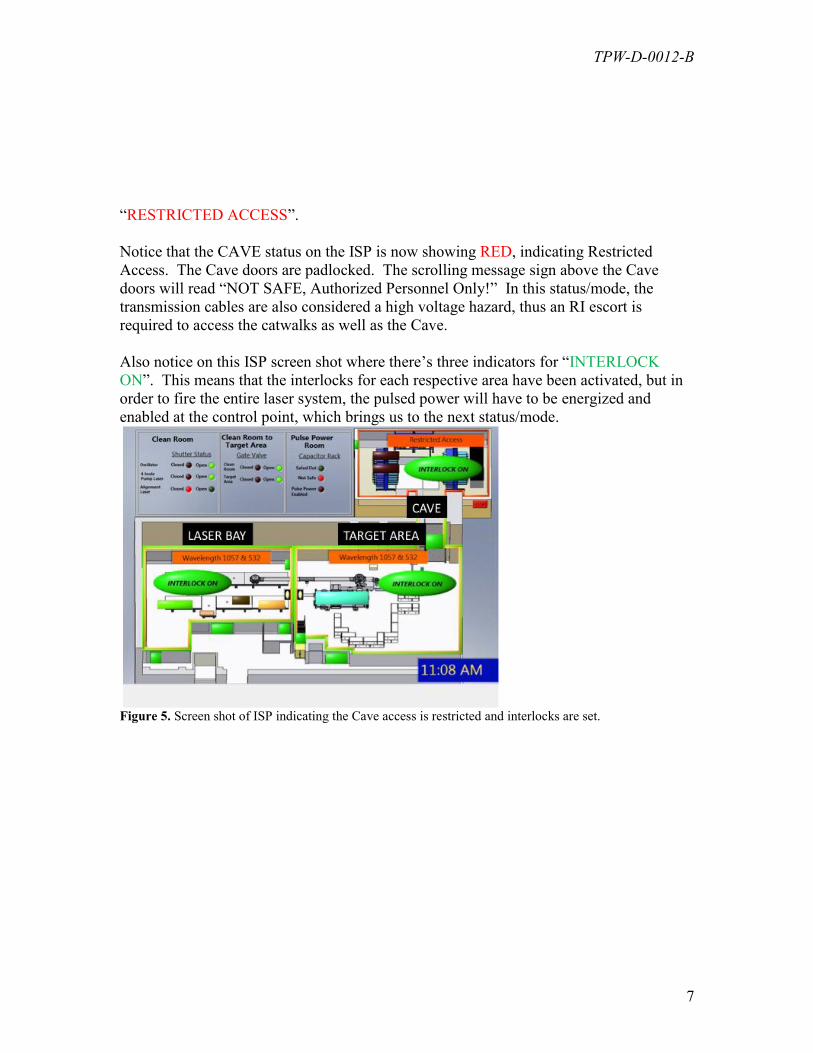
“RESTRICTED ACCESS”.
Notice that the CAVE status on the ISP is now showing RED, indicating Restricted
Access. The Cave doors are padlocked. The scrolling message sign above the Cave
doors will read “NOT SAFE, Authorized Personnel Only!” In this status/mode, the
transmission cables are also considered a high voltage hazard, thus an RI escort is
required to access the catwalks as well as the Cave.
Also notice on this ISP screen shot where there’s three indicators for “INTERLOCK
ON”. This means that the interlocks for each respective area have been activated, but in
order to fire the entire laser system, the pulsed power will have to be energized and
enabled at the control point, which brings us to the next status/mode.
Figure 5. Screen shot of ISP indicating the Cave access is restricted and interlocks are set.
TPW-D-0012-B
8
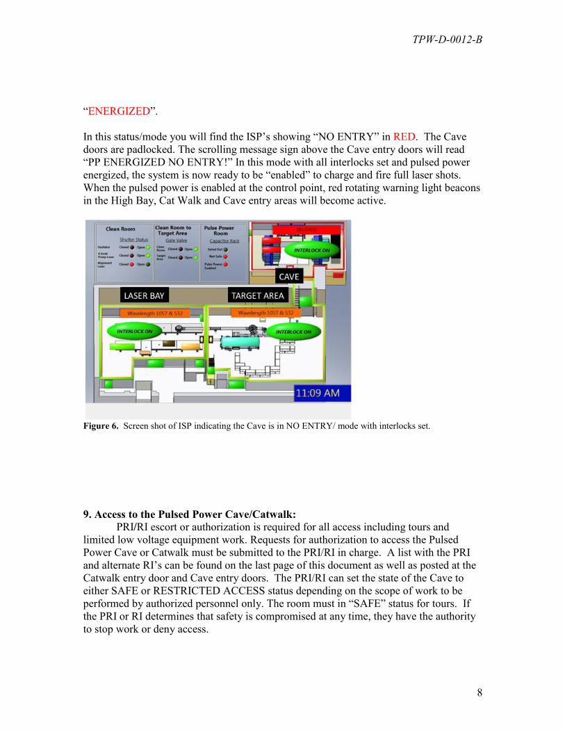
“ENERGIZED”.
In this status/mode you will find the ISP’s showing “NO ENTRY” in RED. The Cave
doors are padlocked. The scrolling message sign above the Cave entry doors will read
“PP ENERGIZED NO ENTRY!” In this mode with all interlocks set and pulsed power
energized, the system is now ready to be “enabled” to charge and fire full laser shots.
When the pulsed power is enabled at the control point, red rotating warning light beacons
in the High Bay, Cat Walk and Cave entry areas will become active.
Figure 6. Screen shot of ISP indicating the Cave is in NO ENTRY/ mode with interlocks set.
9. Access to the Pulsed Power Cave/Catwalk:
PRI/RI escort or authorization is required for all access including tours and
limited low voltage equipment work. Requests for authorization to access the Pulsed
Power Cave or Catwalk must be submitted to the PRI/RI in charge. A list with the PRI
and alternate RI’s can be found on the last page of this document as well as posted at the
Catwalk entry door and Cave entry doors. The PRI/RI can set the state of the Cave to
either SAFE or RESTRICTED ACCESS status depending on the scope of work to be
performed by authorized personnel only. The room must in “SAFE” status for tours. If
the PRI or RI determines that safety is compromised at any time, they have the authority
to stop work or deny access.
TPW-D-0012-B
9
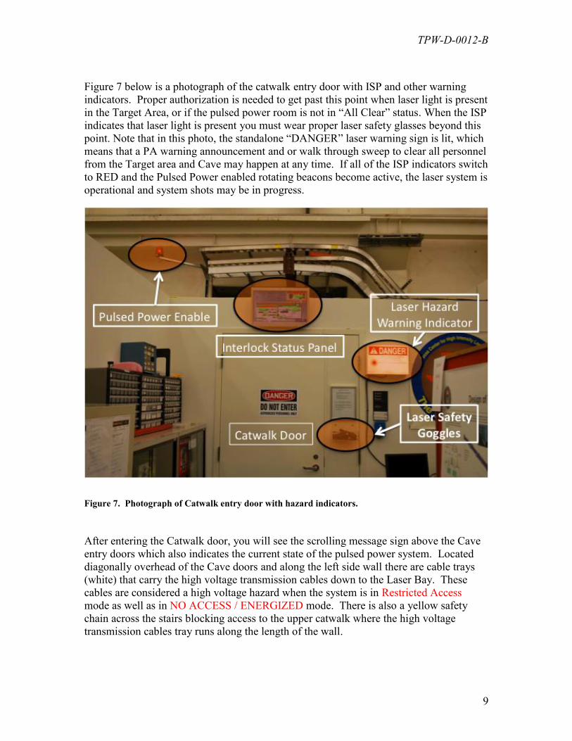
Figure 7 below is a photograph of the catwalk entry door with ISP and other warning
indicators. Proper authorization is needed to get past this point when laser light is present
in the Target Area, or if the pulsed power room is not in “All Clear” status. When the ISP
indicates that laser light is present you must wear proper laser safety glasses beyond this
point. Note that in this photo, the standalone “DANGER” laser warning sign is lit, which
means that a PA warning announcement and or walk through sweep to clear all personnel
from the Target area and Cave may happen at any time. If all of the ISP indicators switch
to RED and the Pulsed Power enabled rotating beacons become active, the laser system is
operational and system shots may be in progress.
Figure 7. Photograph of Catwalk entry door with hazard indicators.
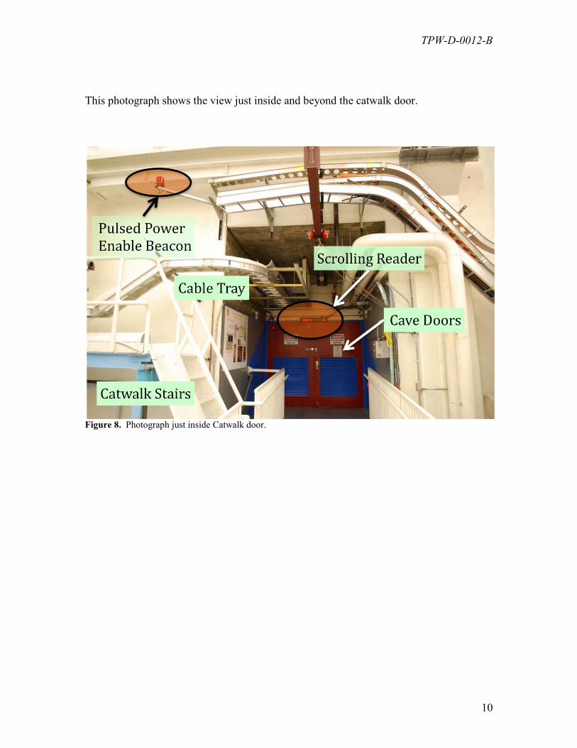
After entering the Catwalk door, you will see the scrolling message sign above the Cave
entry doors which also indicates the current state of the pulsed power system. Located
diagonally overhead of the Cave doors and along the left side wall there are cable trays
(white) that carry the high voltage transmission cables down to the Laser Bay. These
cables are considered a high voltage hazard when the system is in Restricted Access
mode as well as in NO ACCESS / ENERGIZED mode. There is also a yellow safety
chain across the stairs blocking access to the upper catwalk where the high voltage
transmission cables tray runs along the length of the wall.
TPW-D-0012-B
10
This photograph shows the view just inside and beyond the catwalk door.
Figure 8. Photograph just inside Catwalk door.
TPW-D-0012-B
11
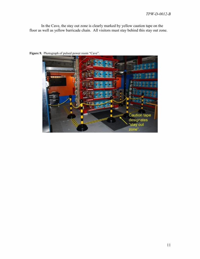
In the Cave, the stay out zone is clearly marked by yellow caution tape on the
floor as well as yellow barricade chain. All visitors must stay behind this stay out zone.
Figure 9. Photograph of pulsed power room “Cave”.
TPW-D-0012-B
12
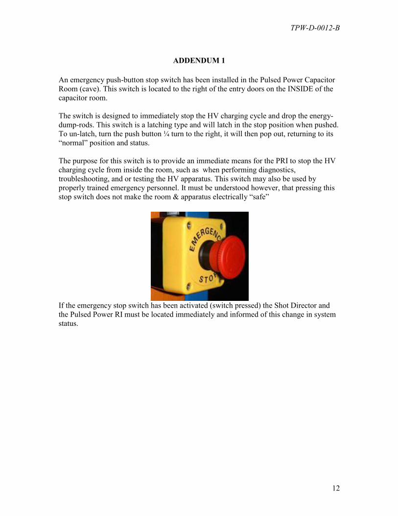
ADDENDUM 1
An emergency push-button stop switch has been installed in the Pulsed Power Capacitor
Room (cave). This switch is located to the right of the entry doors on the INSIDE of the
capacitor room.
The switch is designed to immediately stop the HV charging cycle and drop the energy-
dump-rods. This switch is a latching type and will latch in the stop position when pushed.
To un-latch, turn the push button ¼ turn to the right, it will then pop out, returning to its
“normal” position and status.
The purpose for this switch is to provide an immediate means for the PRI to stop the HV
charging cycle from inside the room, such as when performing diagnostics,
troubleshooting, and or testing the HV apparatus. This switch may also be used by
properly trained emergency personnel. It must be understood however, that pressing this
stop switch does not make the room & apparatus electrically “safe”
If the emergency stop switch has been activated (switch pressed) the Shot Director and
the Pulsed Power RI must be located immediately and informed of this change in system
status.
TPW-D-0012-B
13
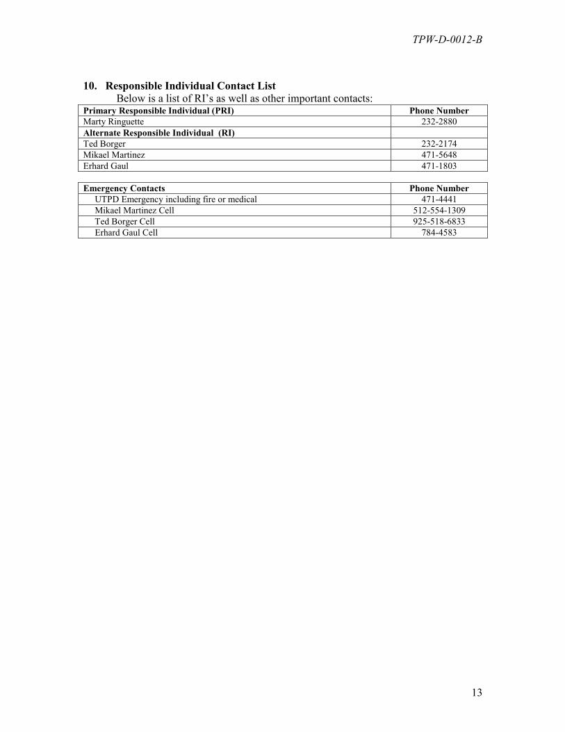
10. Responsible Individual Contact List
Below is a list of RI’s as well as other important contacts: Primary Responsible Individual (PRI) Phone Number
Marty Ringuette 232-2880
Alternate Responsible Individual (RI)
Ted Borger 232-2174
Mikael Martinez 471-5648
Erhard Gaul 471-1803
Emergency Contacts Phone Number
UTPD Emergency including fire or medical 471-4441
Mikael Martinez Cell 512-554-1309
Ted Borger Cell 925-518-6833
Erhard Gaul Cell 784-4583
TPW-D-0012-B
14
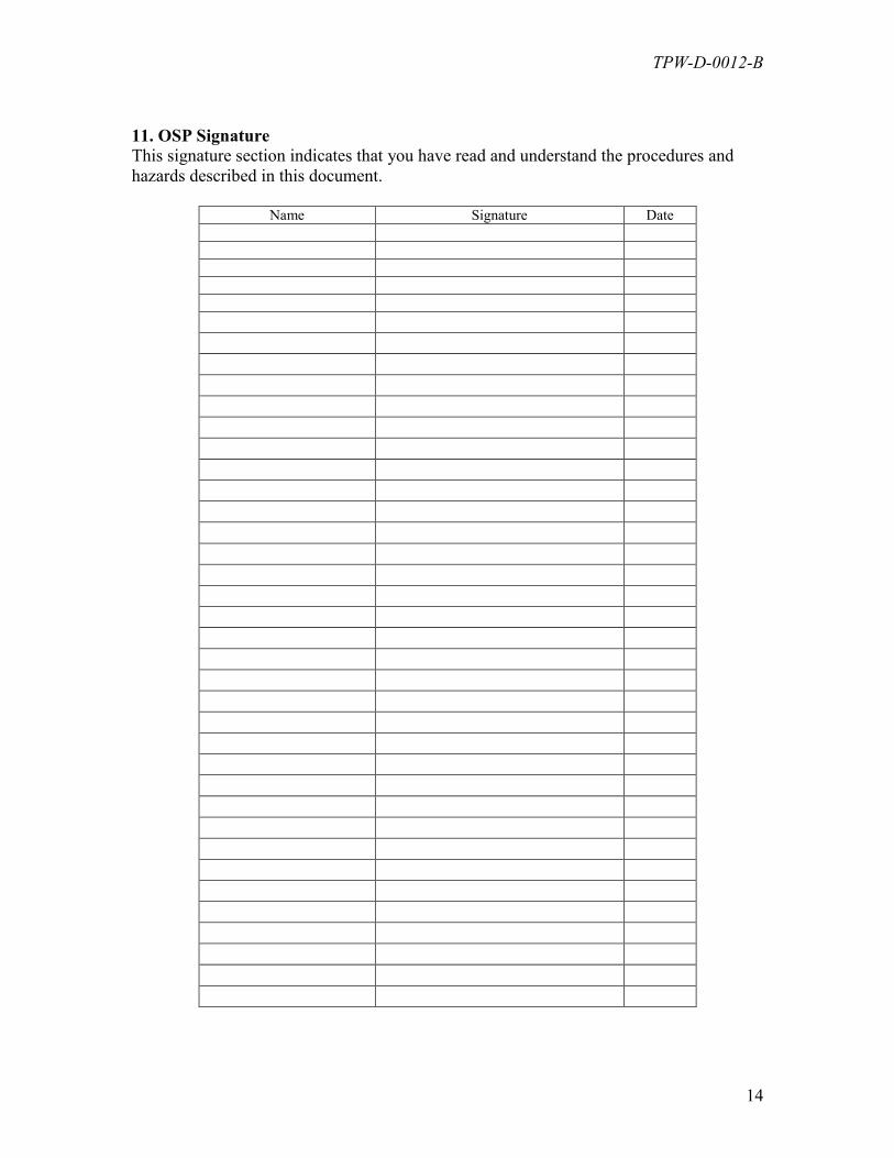
11. OSP Signature
This signature section indicates that you have read and understand the procedures and
hazards described in this document.
Name Signature Date
TPW-D-0012-B
15
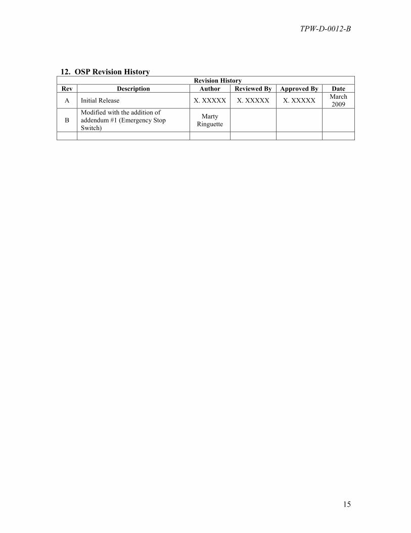
12. OSP Revision History Revision History
Rev Description Author Reviewed By Approved By Date
A Initial Release X. XXXXX X. XXXXX X. XXXXX March
2009
B
Modified with the addition of
addendum #1 (Emergency Stop
Switch)
Marty
Ringuette