Embed Size (px)
Citation preview

I‘ - TECHNICAL ADVISEMENT MEMORANDUM NO. 106-10
OPERATIONAL RELIABILITY ASSESSMENT OF THE GEOS A SPACECRAFT I
M I 1 M I I
II II
PRC D-1056
24 October 1965
P r epar e d by
Charles E. Bloomquist Winifred C. Graham
Jerome A. Kolkin DonaldB. Levinson GPO PRICE S Robert J. Mulvihill
Lynn Roseman CFSTl PRICE(S) S Hugh C. Thompson
Hard copy (HC)
Approved by Microfiche (MF) 1 ’ 7 %
Robert 3 . Mulvihill from ~ ~ f y 6 5
Prepared for National Aeronautics and Space Administration Under Contract Number NASW- 11 80
PLANNING RESEARCH CORPORATION LOS A N G E L E S . CALIF. W A S H I N G T O N , D. C.
https://ntrs.nasa.gov/search.jsp?R=19660014819 2018-05-23T04:45:12+00:00Z

u - *.
I- II I I I I I I I 1 I I I I I IC I I
TABLE OF CONTENTS
Page
1. Introduction . . . . . . . . . . . . . . . . . . . . . . . . . . . . . . . . 1
2. Approach . . . . . . . . . . . . . . . . . . . . . . . . . . . . . . . . . . 1
a. 3 Operation . . . . . . . . . . . . . . . . . . . . . . . . . . . . . . 3 b. Evaluate the Information Available for Diagnosis. . . .
c. Determine What Corrective Actions Are Possible . . . 4
4 d. Set Up and Implement the Procedures . . . . . . . . . . .
Relate Subsystem Failure Modes to System
3. Overall Utilization Method. . . . . . . . . . . . . . . . . . . . . . . 4
a. Possibility of Telemetry Failure . . . . . . . . . . . . . . 4
Procedures . . . . . . . . . . . . . . . . . . . . . . . . . . . . 9 c. History . . . . . . . . . . . . . . . . . . . . . . . . . . . . . . . 10
4. Subsystem Procedures . . . . . . . . . . . . . . . . . . . . . . . . . 10
b. Manner and Frequency of Conducting Subsystem
a. Power Supply . . . . . . . . . . . . . . . . . . . . . . . . . . . 10
b. Optical Beacon and Associated Electronics . . . . . . . 35
c. Thermal Control Subsystem. . . . . . . . . . . . . . . . . . 41
d. Command Subsystem . . . . . . . . . . . . . . . . . . . . . . 45
e. Telemetry Subsystem . . . . . . . . . . . . . . . . . . . . . . 52
Appendix A - Application of Decision Theory to the Operational Analysis of GEOS. . . . . . . . . . . . . . . . . . . . . . . . . 56
65
68
Appendix B - Command List
Appendix C - Telemetry List . . . . . . . . . . . . . . . . . . . . . . . . . . . . . . . . . . . . . . . . . . . . . . . . . .
ii
1 bb
I- I I I I I I I II 4 I I I i I I I I
1.
2.
3.
4.
5.
6 .
7.
8.
9.
10.
11.
12.
LIST OF EXHIBITS
Possible Corrective Actions . . . . . . . . . . . . . . . . . . . Overall Utilization Method .................... Power Supply Procedures ..................... Optical Beacon and Associated Electronics Procedures. . Location of Thermal Cnntrol I~dicatsrs for Telemetry . . Temperature -Time Profile .................... Temperature Values for Subcommutator Channels . . . . . Telltale Temperature C hanne 1s . . . . . . . . . . . . . . . . . Thermal Control Subsystem Diagnostic Routine . . . . . . Thermal Control Subsystem Decision-Action Chart . . . . Command Subsystem Procedure . . . . . . . . . . . . . . . . . GEOS Telemetry Subsystem Failure States . . . . . . . . .
... 111
i
Page
5
7
11
36
A-J -iL.
44
46
47
48
49
51
53

To:
TECHNICAL ADVISEMENT MEMORANDUM NO. 106- 10
Program Manager, Geodetic Satellite Physics and As,tronomy Programs, Office of Space Science and Applications, NASA Headquarters
From: PRC GEOS Reliability Assessment Team
Subject: Operational Reliability Assessment of the GEOS A Space c raft
1. Introduction
This TAM presents the results of an operational reliability
assessment of the GEOS A spacecraft. The purpose of this assessment
was to set up and implement a mefhod to (1) recognize and diagnose pos-
sible "in orbit" failures, and (2) provide corrective actions for these
possible failures.
were prepared for the various subsystems and a r e included in section 4.
The approach that was used is discussed in section 2.
zation method for the routines and procedures is included in section 3.
Diagnostic routines and decision-action procedures
An overall utili-
2. Approach
An important factor which influenced the approach is the type
of data available for the diagnostics. There is, of course, telemetry
data, or , more specifically, commutated (pulse amplitude modulation
(PAM)) telemetry data.
memory readout a r e transmitted via the telemetry transmitter. Another
source of information will be designated a s "experiment response," which
includes details on ground reception of Doppler, SECOR, range/range rate
(R/RR) transponder, and the optical beacon.
straints prohibited reliance on some of the experiment responses a s
normal sources of diagnostic data, but that under abnormal conditions they should be given consideration.
h P 104 -
In addition, the telemetry time marker and
It was felt that time con-
This matter is discussed further
1

Before proceeding, a few statements regarding the time spans in-
volved in this assessment a r e in order. Of course, telemetry data is
available when the spacecraft is in view of a ground station (the NASA
satellite tracking nebvork (STADAN) or the Applied Physics Laboratory
(APL), Johns Hopkins University, Howard County, LMaryland). Approx-
imately five of the Doppler ground stations a r e on direct teletype lines
to APL, while telephone and/or teletype relay communication is avail-
able far the others. ground stations is indicated.
A rapid response thne with respect to these Doppler
The ground stations associated with the other experiments can de-
tect experiment malfunctions rather rapidly.
time is that associated with processing the photographic plates used for
optical beacon observations.
hours; however, the plates may not be processed immediately after ex-
posure. The optical beacon, SECOR, and R/RR transponder ground sta-
tions a r e not part of the GEOS operational control loop, primarily because
a significant delay is usually involved in analyzing the data (on the order of
months). However, specific requests for rapid processing of data samples
by GOCC, the GEOS control center at Goddard, would certainly be honored.
The maximum detection
The time required can be a s little a s a few
The most practical means of monitoring the performance of the
experiments is via telemetry when the spacecraft is in view of a STADAN
o r APL ground station.
Generally, corrective action should be taken as rapidly a s possible.
If the indication of a malfunction is via telemetry, it would be preferable
to issue corrective commands during the same pass of the spacecraft over
the controlling ground station. All the STADAN stations, a s well as APL, have the capability of is suing commands to GEOS.
In view of the objective of rapidity in making diagnoses and taking
corrective action, it was felt that the routines should be somewhat inde-
pendent, i. e., that any desired routine should be accessible without the necessity of first going through several other routines. The time limi-
tations very obviously make computer applications desirable and this, in iurrr, ----1--- :A -Y--:--LI +I.-+ +hn r n r r + ; n o c he ,pet 1 1 n in ar~rh il form that 1 1 l a ~ e u IL U ~ ; P A A Q U L ~ ULUL WAC --------- -r --- ----- they can easily be programmed.
2

I
I Another factor which influenced the approach is the possibility
. that the telemetry indication may not be correct, due to a failure in the
telemetry subsystem. This possibility creates the potential problem of
the observer being deceived. Therefore, means were included where-
ever possible for corroborating telemetry data and identifying states of
telemetry failure.
1 The approach consisted of four tasks: (1) relate subsystem fail-
1- * e nedes ts systen speratis::; (2) evahate the idsrmatieE available I for diagnosis; (3) determine what corrective actions a r e possible; and
(4) set up and implement the procedures.
cussed below.
Each of these tasks is dis-
a . Relate Subsystem Failure Modes to System Operation
This task consisted of determining the "system" e f -
fect of "subsystem" failures.
were known from previous assessment work, so that, in general, the
task involved determining what equipments a r e immediately affected
by the failure and/or what the long-range effect is (e. g., draining a
battery). Since some experiment packages were not assessed, some
assumptions based on engineering judgment were made in this area.
Most of the subsystem failure modes
b. Evaluate the Information Available fo r Diagnosis
As mentioned previously, there a re two sources of
information availablg: information transmitted via the telemetry trans -
mitter, and experiment response. The only experiment response con-
sidered to any extent was Doppler, because it appeared that significant
time delay was generally involved with the ground station response of
the other experiments.
For the possible failure states from subsection 4.a above, it was
determined that most of the needed information was available from te-
lemetry data. This task, then, essentially consisted of specifying what
kinds of telemetry indications to look for in order to identify or diagnose
the pnssible failure s t z t e s .
3

c. Determine What Corrective Actions a re Possible
There a re basically four types of corrective actions
possible, and these a r e itemized in Exhibit 1.
exhibit, the number of corrective actions to choose from is fairly lim-
ited.
that the corrective action specified for any given circumstance was the
best possible .
As can be seen from the
The main requirement of this task was, therefore, to ascertain
d. Set Up and Implement the Procedures
This task required ''inputs" from the three tasks dis-
cussed above in order to provide a timely, systematic method for a r -
riving a t the appropriate corrective action.
subsystem was selected on the basis of providing the most efficient pro-
cedures for that subsystem.
to computer programming.
The format utilized for each
However, each of the formats lends itself
In addition to the subsystem procedures, attention was given to the
overall manner in which these procedures could be utilized, and this is
discussed in section 3.
3 . Overall Utilization Method
The requirements that must be accounted for in the overall
utilization method are: (1) the possibility that the telemetry subsystem
is in some failure state; (2) the manner and frequency of conducting the
procedures fof. each subsystem; ( 3 ) "history" (e. g., care should be taken
in switching in a redundant unit i f a t sometime in the past switching has
already been required).
below. One possible method of overall utilization is included in Exhibit 2.
The implications of each of these a r e discussed
a . Possibility of Telemetry Failure
Telemetry failure is a distinct possibility, and i ts im-
portance can be seen when it is considered that the largest amount of in-
formation is obtained from PAM data.
several easily recognizable failure states (see section 4.e), it would be
efficient to determine f i rs t if the subsystem is in one of these states.
Since the telemetry subsystem has
4

EXHIBIT 1 - POSSIBLE CORRECTIVE ACTIONS
1. Switch in Redundant Unit Commands
Oscillator
Oscillator Oven
Main Converter
Memory Enit
Memory Converter
la and b
2a and b
3a and b
13a and b
30a and b
15a and b Boom Squib Fire and 3.9 Volt Zener IN
Boom Safe and 4.7 Volt Zener IN
2 . Switch Power ON/OFF (either singly or in combinations)
On Main Supply Commands
162 Megacycle On/Off
324 Megacycle On/Off
972 Megacycle On/Off
Telemetry Power On/Off
Telemetry Functions On/Off
Vector Magnetometer OnfOff
162 Megacycle Phase Modulation On/Off
324 Megacycle Phase Modulation On/Off
Telemetry Time Marker On/Off
4a and b
5a and b
6a and b
7a and b
8a and b
9a and b
19a and b
20a and b
32a and b
On Transponder Power Supply
SECOR On/Off
SECOR Select On/Off
R/RR onloff R/RR Select On/Off
Voltage Sensing Override On/Off
Commands
23a and b
24a and b
25a and b
26a and b
31a and b
5

I
I 1' 1 I
I I I H I I I II I I R I I i
m
.
EXHIBIT 1 (Continued)
3. Other Switchable Actions
Solar Power Only h / m f Optical Power Dump
Transponder Power Dump
A?ternate Optical Logic
4. Other Types of Corrective Actions
a. b. C.
d. Send terminal commands.
e . Send no more commands.
f .
g.
Special programming for the optical beacon.
Cease to use the optical beacon.
Plan use between the two cornmand logic units.
Plan use of equipment on main supply.
Ignore some commutated telemetry data.
6
Commands
10a and b
21 22 27 and 28
4 **
I' I I I I I I I I I I I I I I i I I
EXHIBIT 2 - OVERALL UTILIZATION METHOD
1.
5.
6. - 7. c3. A l l .
k 1 2 .
-1 5 c 1 6 :
b e 1 9
Note:
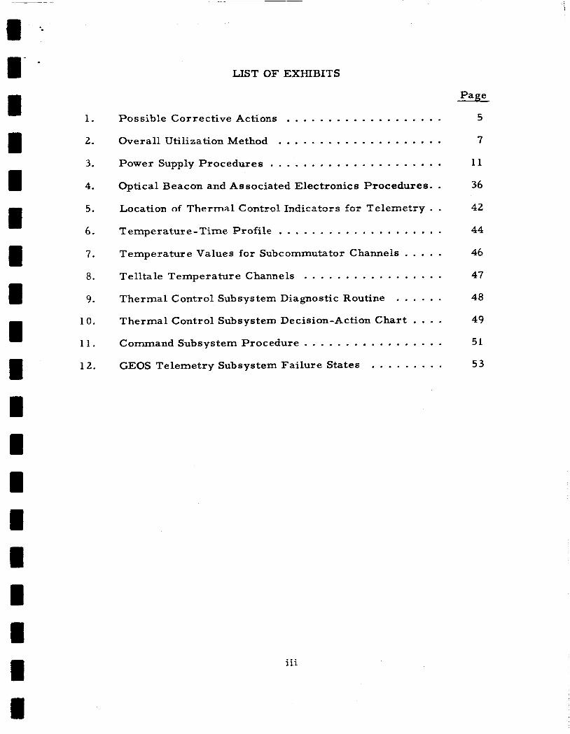
Scan telemetry and compare with preset limits to de- termine i f the telemetry subsystem is in one of its possible failure sbtes. Look only €or those iafiure states which are easily identifiable (see Exhibit 12). Is a l l data usable? (1 )
Is some data usable?
Go to "information lost" mode.
Identify those possible subsystem failures (other than telemetry) which will not now be identifiable and cor- rectable due to the requirement of the routine(s) for data that is not usable.
Remove these routines from the normal sequence and determine whether to go to "information lost" mode.
Should the power supply routines be run?
Run the power supply routines.
Was any power supply malfunction encountered?
Remove any associated routine from the normal sequence and go to next step.
Should the thermal control routines be run?
Run the thermal control routines.
W a s any undesirable condition encountered?
Remove any associated routine from the normal se- quence and go to next step.
Should the optical beacon routines be run?
Run the optical beacon routines.
Was any optical beacon malfunction encountered?
Remove any associated routine from the normal sequence and go to the next step.
Perform any updating and/or logging required and return to step 1 if desired.
(1) Y - Yes; N - No.
7

If so, use of the procedures which require data that is recognized a s in-
valid should be inhibited.
The problem of how to proceed when telemetry data is lost must
then be faced. One way to handle this is to establish a dichotomy of op-
erating modes, namely, an "information available" mode and an "infor-
mation lost" mode. The "information available" mode is covered by the
subsystem procedures discussed in subsection 3. b.
The "information lost" mode presents problems of a dynamic nature,
since before the fact it cannot be stated with certainty what the character-
istics of this mode will be.
follows:
Some of the possible characteristics a r e a s
0 The amount of information that must be lost to constitute the "information lost" mode will depend upon the s ta tus of the spacecraft a t that time. For example, i f some previous failure has rendered the optical beacon useless, the loss of optical beacon data would be of no consequence. Another example is loss of information that is needed to diagnose a failure which has a very low probability of occurrence. deal of data can be lost with insignificant adverse effects i f it applies to situations like those in the examples. On the other hand, i f situations like these do not exist, even the loss of a small amount of data will be serious.
The information can be lost "all a t once" (e.g., loss of the transmitter) or in serial fashion (e. g . , loss of several single channels nonsimultaneously over a fairly long period).
0 In some cases, experiment response could conceivably provide very useful information. To determine what these cases were, one would have to consider any remaining valid telemetry data, along with the experiment response information, and then find the failure states which this information would be useful in di- agno s ing .
Therefore, a great
0
From the above discussion, it can be seen that the result of losing
information is uncertainty a s to (1) whether a failure might have occurred,
o r (2) what action to take when it is known that a failure has occurred.
Since decision theory provides mathematical methods for minimizing risk
in the face of uncertainty, its application might prove useful. The appli-
cation of decision theory to the case of loss of single telemetry channels
is presented in Appendix A.
An application of decision theory to decisions involving the GEOS A
redundant command converter was carried out to determine the effect of
failure of a single telemetry channel on the decision-action procedures.
8
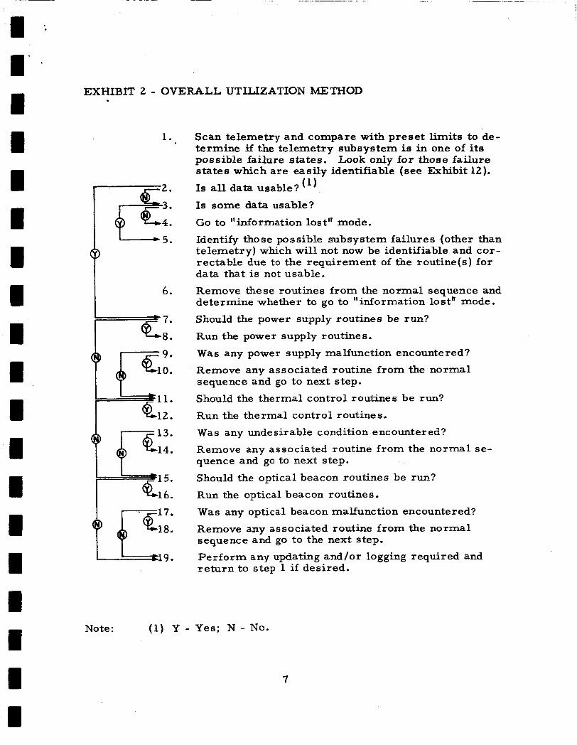
I' It was demonstrated that if corroborating evidence based on data from
other nonfailed telemetry channels is utilized, then no significant uncer-
tainty remains with respect to decision making; thus the problem of ob-
taining incorrect telemetry data on a single channel and therefore taking
a wrong action was found to be inconsequential if corroborating evidence
from other telemetry channels is utilized.
decision-action charts presented in this document reflect the philosophy of
seeking corroborative evidence.
1 I W I I
The diagnostic routines and
The application of decision theory to GEOS operational reliability in
the grosser situation where there is substantial loss of telemetry and con-
comitant increase in uncertainty is expected to yield results which a re non-
intuitive. This application is presently under consideration.
It appears that the following choices a r e available a s operation
I methods f o r the "information lost" mode:
I t I I I I I I 8 I
(1)
(2)
Transmit a set of predetermined terminal com- mands and then transmit no further commands.
Use decision theory to determine what the ter- minal commands should be, transmit them, and issue no further commands.
Continue operation and use decision theory to determine all actions.
(3)
(4) Do nothing.
(5) Combine some of above a s conditions indicate, e. g., use (3) a s long a s possible and then (1) or (2).
The case of the "information lost" mode is being given detailed
study in a continuing effort.
b. Manner and Frequency of Conducting Subsystem Procedures
For the case of no loss o r insignificant loss of telem-
etry information, a suggested method is as follows:
0 Utilize the optical beacon electronics routine only when per- tinent subcommutator channels, photographs of beacon flashes, and/or memory readout indicate trouble.
Utilize thermal control routine whenever telemetry data is r e ceived .
0
9

0 Utilize power supply routine periodically (for example, daily) and whenever called for by other routines.
Exhibit 2 is a graphic presentation of the overall utilization
method.
c. History
This is more or less a "bookkeeping" task. It includes
such things a s the previously mentione4 exmipie of preventing a i o i i t i e
from calling for switching in a redundancy when switching has already
been necessary in that redundancy. It should be noted, however, that it
might be desirable to switch back to a degraded redundant unit if a more
serious degradation was found in the other redundant unit.
4. Subsystem Procedures
a. Power Supply
Since the electrical power subsystem is virtually the
heart of the spacecraft electronics and is vital to the system operation,
a malfunction of any sor t may be indicative of a failure in this subsys-
tem. Therefore, i f a malfunction is evidenced in another subsystem
and the diagnostics for that subsystem either indicate that the trouble
is not in that subsystem or do not provide information to determine the
cause of the malfunction, the power supply diagnostics should be carried
out.
Because of its importance and the fact that a majority of the com-
mands and telemetry indications a r e associated either directly or in-
directly with the power supply, the scope for this subsystem is greater
than for any other.
ent; they a re listed in Exhibit 3.
There a r e 37 procedures, most of them independ-
Some of the general aspects of the procedures should be noted.
The first of these concerns the definition of the "high" or "low" indi-
cation specified throughout.
indications should not be specified at this time.
It w a s felt that a numerical value for these
Therefore, "low" shbuld
10

EXHIBIT 3 - POWER S U P P L Y PROCEDURES
A. Indication -
Procedure
1 - 3 .
I - 6 .
B. Indication - Procedure
1.
I*.
Main Power Supply, Solar Current Low (Commutator (C] 1, Channel (Ch) 4)
Eclipse 3 (1 1 Normal indication, no further action required.
Transmit command (Cmd) 10a (solar only on) and go to step 4.
Are telemetry and Doppler being received correctly?
Telemetry (TM) malfunction on C1, Ch 4. Apply correction factor if possible; otherwise, ignore this channel henceforth. Transmit Cmd 10b if desired.
Indicates malfunction in main solar array. that main battery remains unloaded until plans can be formulated to conserve remaining battery power.
Ascertain
Main Power Supply, Battery Current Low (Cl, Ch 5)
Transmit Cmd 10a (solar only on) when not in eclipse.
Does C1, Ch 5, now indicate normal current?
Main battery is defective. equipment on main supply only in sunlight. to charge battery if situation warrants.
Check main battery voltage (C2, Ch 5) and go to step 5.
Is voltage normal?
Transmit Cmd 10b (solar only off) and wait for eclipse; then go to step 7.
A r e telemetry and Doppler being received correctly?
T M malfunction on C1, Ch 5. Apply correction factor if possible; otherwise, ignore this channel henceforth and transmit Cmd 10b if desired.
Same as step 3 above.
Plan further operation of Attempt
Note: (1) Y - Yes; N - No.
11

~~
EXHIBIT 3 (Continued)
C. Indication - Procedure
Main Power Supply, Battery Current High (Cl , Ch 5)
1. If in eclipse, unload main supply and wait until sun- light to perform following procedure. eclipse, go to step 2.
If not in
Is battery on charge or discharge? (1 1
Indicates high charge rate.
loading. If no other malfunction is indicated, the battery should be kept on charge and additional equipment should be turned on. A safe sequence would be to transmit "solar only on" (Cmd loa), followed by a turn-on of appropriate equipment, followed by "solar only off" (Cmd lob).
Is main bus voltage low (C2, Ch 4)?
Go to procedure Y.
Transmit the following commands singly to determine if malfunction is in one of the loads:
a.
b.
c.
d.
e.
Did current return to normal or is battery on charge?
Leave malfunctioning unit off and restore other units as desired.
Switch to alternate main converter (Cmd 3a or 3b) and go to step 10.
Did current return to normal o r is battery on charge?
Malfunction in main converter. with selected converter and restore other units a s des ired.
Either a high leakage path in wiring harness o r a telemetry malfunction on this channel. persists for several orbital periods with no detectable consequences, assume that a telemetry channel mal- function exists. Apply correction factor if possible; otherwise, ignore this channel henceforth. Restore commands as desired.
This could come about Z S Z r e S * d t G f high Solar array C l l t p t a d li&ht
162 MC off (Cmd 4b)
324 MC off (Cmd 5b)
972 MC off (Cmd 6b)
Telemetry time marker off (Cmd 32b)
Vector magnetometer off (Cmd 9b)
Continue operation
If indication
Note: ( 1 ) C - Charge; D - Discharge.
12

EXHIBIT 3 (Continued)
Rationale
Indication is that battery current is high, but it is not known if this is charge or discharge o r if the spacecraft is in eclipse or sunlight. craft is in eclipse, a safe action would be to shut off all main supply loads and wait until sunlight in order to isolate the fault.
If the battery is excessively discharging and the space-
If the fault is not a dead short but is of such magnitude that is r o d d be compensated fo r hy rerr?nval of loadsi then the battery, i f it is discharging in sunlight, will revert to a charging condition after the appropriate amount of load is removed.
The rest of the procedure is to determine if a faulty load is present and, if so, isolate it, to determine if the battery is at fault, and to determine if a fault in the wiring harness is present. If none of these determinations i s positive after several orbits, then it can reasonably be assumed that there is a malfunction in the telemetry subsystem.
13

EXHIBIT 3 (Continued)
D. Indication - Procedure
E. Indication -
Procedure
t 2 .
c
k 8 .
Main Converter, Input Current Low ( C l , Ch 6 )
Are main converter t21-volt (v) current (Cl, Ch 24) and main converter -32v current (Cl , Ch 25) normal? Are telemetry, Doppler, and vector magnetometers normal ?
TM malfunction on C1, Ch 6. Apply correction factor if possible; otherwise, ignore this channel henceforth.
Main converter malfunction. Switch to alternate con- verter (Cmd 3a or 3b).
Main Converter, Input Current High (C1, Ch 6 )
Are telemetry, Doppler, and vector magnetometers normal?
Transmit the following commands singly to determine if the malfunction is in one of the loads:
a. 162 megacycle (MC) off (Cmd 4b)
b. 324 MC off (Cmd 5b)
C. 972 MC off (Cmd 6b)
d. Telemetry time marker off (Cmd 32b)
e. Vector magnetometer off (Cmd 9b)
W a s malfunction isolated?
Leave malfunctioning unit off and restore others as desired.
Switch to alternate converter (Cmd 3a or 3b) and go to step 6. Is indicated current still too high?
Malfunction was in converter.
This indicates that the malfunction is in telemetry. Turn off all telemetry equipment (Cmd 7b) and re- store operation to original converter if desired. Determine whether the malfunction was only in C1, Ch 6, and if it should be corrected or ignored, o r ,whether the malfunction is such that it can cause damage, in which case telemetry should remain off henceforth .
14
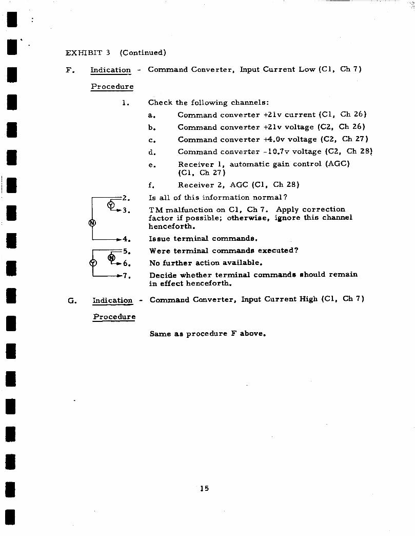
EXHIBIT 3 (Continued)
F. Indication - Command Converter, Input Current Low (Cl, Ch 7 )
Procedure
1. Check the following channels:
a. Command converter +21v current (Cl, Ch 26) b. Command converter +21v voltage (C2, Ch 26) C. Command converter 4 . 0 ~ voltage (C2, Ch 27 ) d. Coniniad coiivertei -? [ f . ?~ voltage (CZ, Ch 28)
e.
f. Receiver 2, AGC (Cl , Ch 28)
Is all of this information normal?
T M malfunction on C1, Ch 7. Apply correction factor if possible; otherwise, ignore this channel henceforth . Issue terminal commande.
Were terminal commande executed?
No further action available.
Decide whether terminal commands should remain in effect henceforth.
Receiver 1, automatic gain control (AGC) ( C l , Ch27)
I?:: G. Indication - Command Converter, Input Current High (Cl, Ch 7 )
Procedure
Same as procedure F above.
15

I 1 I
m IU I I I
EXHIEIT 3 (Continued)
H. Indication - Transponder Power Supply, Solar Current Low (Cl, Ch 8)
Procedure
Eclipse?
Normal indication.
Transmit the following commands to remove all loads:
a. 3 . 9 ~ command zener to alternate position !Cmd 1% cr 1%)
b. Transponder power dump off (Cmd 22al )
C. SECOR off (Cmd 23b)
d. R / R R transponder off (Cmd 25b)
e. Voltage sensing switch override off (Cmd 31b)
No further action required.
4. Check transponder battery charge rate (C1, Ch 9)
Is charge rate normal?
TM malfunction on C1, Ch 8. Apply correction factor if possible; otherwise, ignore this channel henceforth.
Indicates malfunction in transponder solar array. Plan further operation to conserve remaining battery power.
7.
1 1 I II 1
16

EXHIBIT 3 (Continued)
1. Indication - Transponder Power Supply, Solar Current High (Cl, Ch 8)
Procedure
1.
I k 8 .
Transmit the following commands to remove all loads:
a. 3 . 9 ~ command zener to alternate position (Cmd 15a or 15b)
A ranqmiider power durrq off ( ~ m d 22ai1 rn _- D.
C . SECOR off (Cmd 23b)
d.
e. Does cu r ren t return to normal?
Indicates load short but not in battery. Reapply loads singly until fault is isolated. Operate without malfunctioning unit henceforth and restore other loads as desired.
Is battery charge rate high (Cl, Ch 9)? Turn on power dumps (Cmd 22b2) and go to step 6 . Does solar current return to normal?
Proceed normally and restore loads as desired.
Transmit commands to apply the following loads and go to step 9: a. SECOR on (Cmd 23a and 24a)
b. R / R R transponder (Cmd 25a)
C.
Does current return to normal?
Remain in this load condition until eclipse and pro- ceed with normal eclipse mode operation.
No further action. If the transponders function normally, proceed with normal operation.
Indicates either a harness short o r malfunction on this telemetry channel.
R / R R transponder off (Cmd 25b)
Voltage sensing switch override off (Cmd 31b)
Voltage sensing switch (Cmd 31a)
17

1 ’- I
EXHIBIT 3 (Continued)
J. Indication - Transponder Power Supply, Battery Current High (Cl, Ch 9 )
Procedure
1.
6pc:
L 8 .
L--cll.
Check battery temperature (C2, Ch 8).
Is temperature high?
Utilize power dump (Cmd 22b2).
Is battery on charge or discharge?
Utilize power dump (Cmd 22b2) and go Does current return to normal?
Proceed normally in this mode,
3 step 6 .
Transmit the following commands to apply all loads and go to step 9: a. SECOR on (Cmd 23a)
b. R/RR transponder on (Cmd 25a)
C. 3 . 9 ~ command zener (Cmd 15a)
d. Voltage sensing switch (Cmd 31a)
Does charge rate return to normal?
Continue with maximum loading until eclipse operation and then proceed normally.
No further action available. and proceed normally. temperature. Restore loads a s desired.
Assume telemetry e r ro r Periodically check battery
Transmit the following commands to remove all loads and go to step 13: a. SECOR off (Cmd 23b)
b. R / R R transponder off (Cmd 25b)
c.
d.
Voltage sensing switch (Cmd 31b)
Power dumps off (Cmd 22bl)
e. 3 . 9 ~ command zener to alternate position (Cmd 15a or 15b)
Does current return to normal?
Indicates load short. is isolated. forth and restore other loads as desired.
Reapply loads singly until fault Operate without malfunctioning unit hence-

EXHIBIT 3 (Continued)
Eclipse ?
Turn off power dump (Cmd Z l a l ) and go to step 3.
Does current return to normal? ci:
@ +-Fa . Proceed with normal operation.
5. Check current during flash sequence. If current is low during flash sequence, the telemetry sense resistor is open. Discontinue use of beacon until operation plan can be formulated.
Switch to AOL operation by Cmd 27a and note battery -6.
K. Indication - Optical Power Supply, Battery Temperature High (Cl, Ch 16)
Procedure
Is optical battery charge rate high (Cl, Ch 19)?
Ut i l i ze power dump (Cmd 21b2) and go to step 3. Does charge rate remain high (including eclipse periods )?
TM malfunction on C1, Ch 16. Apply correction factor if possible; otherwise, ignore this channel henceforth.
Proceed normally with power dump in position 21b2 until situation warrants change.
Unless battery has heated up due to general temperature rise of the spacecraft, this indicates telemetry mal- function on C1, Ch 16.
3.
Restore power dump if desired.
5.
6 .
L. Indication - Optical Power Supply, Battery Current Low (Cl, Ch 19)
Procedure
19

1 - 1' - I I il 1 ~I iI
I I I I I II 1 I I I
~II
EXHIBIT 3 (Continued)
M. Indication - Optical Power Supply, Battery Current High (Cl, Ch 19)
Procedure
-7.
I 1 0. -11.
1 - 1 4 .
17.
1 2 0 .
Eclipse ?
Check battery temperature (Cl, Ch 16) and go to step 3.
Is temperature high?
Utilize nowei r dtxr~p (Crrrd ZlbZ) and go to step 5 ,
Is current still high?
TM e r ro r on C1, Ch 19. Apply correction factor if possible; otherwise, ignore this channel hence- forth. Restore power dump if desired.
Proceed with normal operation with power dump in 21b position until situation warrants change.
Is optical bus voltage (C2, Ch 18) high?
TM er ror on C1, Ch 19. Apply correction factor if possible; otherwise, ignore this channel henceforth.
Go back to step 4.
Switch to alternate memory converter (Cmd 30a or 30b) and go to step 12.
Is current still high?
Malfunction was in converter.
Turn power dump off (Cmd 21al) and go to step 15.
Is current still high?
Proceed normally with power dump in position 21al until situation warrants change. original converter if desired.
Switch to alternate memory (Cmd 13a o r 13b) and go to step 18.
Is current still high? Malfunction in memory. Continue operation with selected memory and restore other commands if desired.
If beacon is functioning normally, assume telemetry malfunction on C1, Ch 19, and proceed normally or attribute condition to high leakage path.
2
Restore use to
20

EXHIBIT 3 (Continued)
N. Indication - Memory Converter, Input Current Low (Cl , Ch 20)
Procedure
1 . Check the following channels:
a. Memory converter t10.7 voltage (Cl, Ch 21)
b. Memory converter t4.0 voltage (Cl, Ch 22) C. Memory converter -10.7 voltage (Cl, Ch 23)
Is this information normal?
TM malfunction on C1, Ch 20. Apply correction factor if possible; otherwise, ignore this channel henceforth.
Switch to alternate memory converter (Cmd 30a or 30b) and go to step 5.
Are indications normal ?
Malfunction was in memory converter.
Switch to alternate optical logic (AOL) operation and restore original converter if desired.
4, IT: + - " :
7.
0. Indication - Memory Converter, Input Current High (Cl, Ch 20)
Procedure
1. Switch to alternate memory converter (Cmd 30a or 3 Ob).
Is reading normal?
Malfunction was in memory converter.
Switch to alternate memory unit (Cmd 13a or 13b) and go to step 5. Is input current still high?
Malfunction was in memory unit, selected memory unit and restore converter if desired.
Check the following channels:
a. Memory converter t10.7 voltage (Cl, Ch 21)
b. Memory converter 6.0 voltage (Cl, Ch 22) c. Memory converter -10.7 voltage (C l , Ch 23)
Is this information normal?
TM malfunction on C1, Ch 20. Apply correction factor if possible; otherwise, ignore this channel henceforth and restore commands if desired.
Switch to AOL operation.
+7Zi Continue use with B"Bi
21

EXHIBIT 3 (Continued)
P. Indication - Memory Converter, t 10 .7~ Low (Cl, Ch 21)
Procedure
1, Select alternate memory converter (Cmd 30a or 30b).
Is voltage still low? Malfunction in memory converter.
Select alternate memory unit (Cmd 13a or 13b) and go to step 5. Is voltage still low?
Malfunction in memory.
Check operation of optical beacon and go to step 8. Is beacon operating correctly?
TM malfunction on C1, Ch 21. Apply correction factor if possible; otherwise, ignore this channel henceforth. Restore converter and memory unit if desired.
Restore original converter 17:: if desired.
i" ii Switch to AOL operation.
Q. Indication - Memory Converter, i 4 . 0 ~ Low (Cl, Ch 22)
Procedure
Same as procedure P above.
R. Indication - Memory Converter, -10.7~ Low (C l , Ch 23)
Procedure
Same as procedure P above.
22

EXHIBIT 3 (Continued)
S. Indication - Main Converter, t21v Current Low (Cl, Ch 24)
Procedure
1. F 2.
I -3.
1 9 .
Check for normal operation of telemetry commutators and vector magnetometer. malfunction o r errat ic operation?
TM malfunction on C1, Ch 24. Apply correction factor if possible; otherwise, ignore this channel hencefcrth.
Switch to alternate main converter (Cmd 3a or 3b) and go to step 4.
Is current normal now?
Malfunction in main converter.
Send telemetry on and off commands (Cmds 8a and 8b) to test for relay contact closure, and go to step 7.
Is current normal now?
Fault was in Cmd 8 relay contacts. operation.
If malfunction indications a r e associated with the vector magnetometer, discontinue further operations with it (Cmd 9b). If malfunctions a r e associated with telemetry, continue telemetry operations to the extent possible and until more serious symptoms occur.
Are there indications of
Proceed with normal Restore original converter if desired.
T. Indication - Main Converter, +21v Current High (Cl, Ch 24)
Procedure
1. Switch to alternate main converter (Cmd 3a or 3b). Is reading normal?
Malfunction was in main converter.
Switch off vector magnetometer (Cmd 9b) and go to step 5. Is reading normal?
Malfunction in vector magnetometer. main converter if desired.
Switch off telemetry functions (Cmd 8b) and decide whether they should remain off henceforth.
Q.7;; Restore original
23
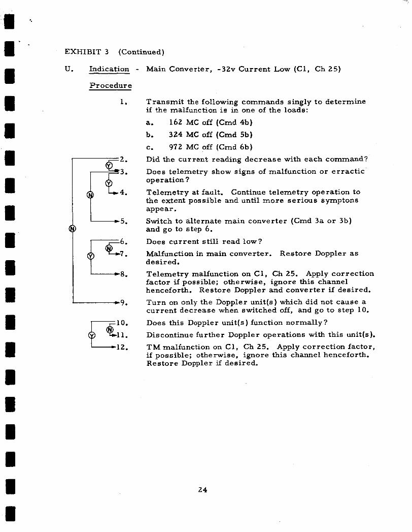
EXHIBIT 3 (Continued)
U. Indication - Main Converter, -32v Current Low (Cl, Ch 25)
Procedure
1. Transmit the following commands singly to determine if the malfunction is in one of the loads:
a. b. c.
2. Did the current reading decrease with each command?
3. Does telemetry show signs of malfunction or erractic operation ?
4. Telemetry at fault. Continue telemetry operation to the extent possible and until more serious symptom appear.
Switch to alternate main converter (Cmd 3a or 3b) and go to step 6. Does current still read low?
Malfunction in main converter. desired.
Telemetry malfunction on C1, Ch 25. Apply correction factor if possible; otherwise, ignore this channel henceforth. Restore Doppler and converter if desired.
Turn on only the Doppler unit(s) which did not cause a current decrease when switched off, and go to step 10.
Does this Doppler unit(s) function normally?
162 M C off (Cmd 4b) 324 M C off (Cmd 5b) 972 MC off (Cmd 6b)
5.
Restore Doppler as
1 9 .
i-5;: Discontinue further Doppler operations with this unit(s).
12. TM malfunction on C1, Ch 25. Apply correction factor, if possible; otherwise, ignore this channel henceforth. Restore Doppler if desired.
24

EXHIBIT 3 (Continued)
V. Indication - Main Converter, -32v Current High (C l , Ch25)
Procedure
1.
1 4 .
1 7 .
I 1 0.
IC::: 1 - 1 3 .
Transmiit the following commands singly to determine if the malfunction is in one of the loads:
a. 162 MC off (Cmd 4b)
b. 324MC off (Cmd 5b)
c. 972 MC off (Cmd 6b)
The malfunction may be isolated through a process of elimination by comparing -32v current with the s u m of current for the two pertinent completely unfailed Doppler units which a r e turned on in each case.
Was the malfunction isolated?
Leave malfunctioning unit off and restore others as desired,
Switch to alternate main converter (Cmd 3a or 3b) and go to step 5.
Is reading normal?
Malfunction in main converter. de sired . Turn the Doppler units back on singly, look for signs of malfunction, and go to step 8.
Is Doppler functioning normally?
T M malfunction on C1, Ch 25. Apply correction factor if possible; otherwise, ignore this channel henceforth. Restore Doppler and converter i f desired.
Turn off telemetry system (Cmd 7b). Is Doppler functioning normally?
Malfunction in telemetry. without telemetry.
Malfunction in Doppler. quencies which show no malfunction. and telemetry if desired.
Restore Doppler if
Decide whether to operate
Operate only with those fre- Restore converter
25

EXHIBIT 3 (Continued)
W. Indication - Procedure
1.
LT':: I L 4.
1 7 .
X. Indication - Procedure
1.
l-w 4.
k 7 .
Command Converter, +21v Current Low (Cl, Ch 26)
Check t21v voltage (C2, Ch 26) and command converter input current (Cl, Ch 7).
Is command converter input voltage high and/or has input current de creas ed ?
Telemetry malfunction on C1 , Ch 26. Apply correction factor i f possible; ofb-erdee, igmre +this chamel henceforth.
Send terminal commands and go to step 5.
Were terminal commands executed?
No further action available.
Send no further commands if possible, and continue to take available telemetry and experimental data.
Command Converter, t21v Current High (Cl, Ch 26)
Check t21v voltage (C2, Ch 26) and converter input current ( C l , Ch 7).
Is command converter input voltage low and/or has input current increased?
Telemetry malfunction on C1, Ch 26. Apply correction factor if possible; otherwise, ignore this channel henceforth.
Send terminal commands and go to step 5.
Were terminal commands executed?
No further action available.
Send no further commands if possible, and continue to take available telemetry and experimental data.
26

EXHIBIT 3 (Continued)
Y. Indication - Main Power Supply, Bus Voltage Low (C2, Ch 4)
Pr oce du r e
1.
gc:::
-1 7.
Switch to alternate main converter (Cmd 3a o r 3b).
Does voltage return to normal?
Malfunction in main converter.
E cl ip s e ?
Transmit "solar only off" (Cmd lob) and go to step 6. Does voltage return to normal?
Proceed with normal operation. if de s i r ed.
Transmit "solar only on" (Cmd loa) and go to step 9. Does voltage return to normal?
Schedule sun operation only for further use. Restore converter if desired.
Transmit the following commands singly to determine if the malfunction is in one of the loads:
a. b.
c.
d.
e. W a s malfunction isolated?
Leave malfunctioning unit off and restore others if desired.
Has telemetry or Doppler shown any signs of mal- function or erratic operation?
Is main converter -32v voltage low?
Either a high leakage path in wiring harness o r a telemetry malfunction on this channel. persists for several orbital periods with no detectable consequences, assume that a telemetry channel mal- function exists. Apply correction factor if possible; otherwise, ignore this channel henceforth. Restore commands as desired.
No further telemetry operation possible. other commands as desired.
Restore converter
162 MC off (Cmd 4b)
324 MC off (Cmd 5b) 972 MC off (Cmd 6b)
Telemetry time marker off (Cmd 32b)
Vector magnetometer off (Cmd 9b)
If indication
Restore
27

EXHIBIT 3 (Continued)
Z. Indication - Main Power Supply, Battery Voltage Low'') (C2, Ch 5)
Procedure
1. Transmit solar only on (Cmd loa) and wait until not in eclipse to go to step 2. Is voltage still low? fa;:: Go to procedure Y. m -. - 4. I ransnGi solar o d y o€f {Cmd 1 ab) and go to step 5. Did battery charge? 13:: Proceed with normal operation.
7. No further action. Schedule sun operation only.
AA. Indication - Main Power Supply, Battery Temperature High (C2, Ch 6 )
Procedure
1. Check main battery current (Cl, Ch 5).
Is current high? (fT+t: Go to procedure C. Unless battery has heated up due to general temperature r ise of spacecraft, this indicates telemetry malfunction on C2, Ch 6.
4.
Note: (1) Low voltage may be considered a s any value g 8 . 4 ~ . 100 percent depth of discharge for these cells is l.Ov, and 2 . 4 ~ is equivalent to 1 . 0 5 ~ per cell for eight cells.
28
I - 1’ *
EXHIBIT 3 (Continued)
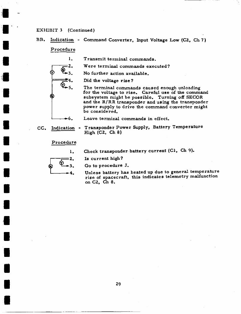
BB. Indication - Command Converter, Input Voltage Low (C2, Ch 7 )
Procedure
1. Transmit terminal commands.
Were terminal commands executed?
No further action available.
Did the voltage r i s e?
The terrr,i-,a? csrr;rr;zmds racsed exzzug’h sdcading for the voltage to rise. Careful use of the command subsystem might be possible. and the R / R R transponder and using the transponder power supply to drive the command converter might be considered.
Leave terminal commands in effect.
Turning off SECOR
CC. Indication - Transponder Power Supply, Battery Temperature High (CZ, Ch 8)
Procedure
1. Check transponder battery current (Cl, Ch 9).
Is current high?
G o to procedure J. Unless battery has heated up due to general temperature rise of spacecraft, this indicates telemetry malfunction on C2, Ch 8.
4.
29

EXHIBIT 3 (Continued)
DD. Indication - Transponder Power Supply; Bus Voltage Low (C2, Ch 9 )
Procedure
1.
K2* Q--3.
u 4.
Transmit the following commands to remove loads:
a. b. SECOR off (Cmd 23b)
c.
Is voltage still low?
Transmit the following commands and go to step 4:
a.
b. Is voltage etill low?
Check the transponder battery current (Cl, Ch 9 ) and go to etep 6. Is battery on charge or discharge?
Is current high?
Indicates defective battery.
Unless abnormal operation is noted in the future, this would indicate a telemetry malfunction on C2, Ch 9. Restore loads as desired.
Is current high?
Indicates random short or uncalibrated telemetry res istor.
Does solar current (Cl , Ch 8) equal the battery current?
Indicates random short on the transponder bus. further action available.
Telemetry malfunction on C2, Ch 9. Apply correction factor if possible; otherwise, ignore this channel henceforth. Restore loads a8 desired.
Malfunction lo cat ed . unit and restore others if desired.
Power dump off (Cmd 22al )
R/RR transponder off (Cmd 25b)
3 . 9 ~ command zener to other position (Cmd 15a or 15b)
Voltage sensing switch override off (Cmd 31b)
No further action available.
No
Proceed without malfunctioning
30

EXHIBIT 3 (Continued)
EE. Indication
Procedure
1.
L 4 .
1 - 7 .
gg::: 16.
Optical Power Supply, Battery (Bus) Voltage Low (C2, Ch 18, subcommutator Ch 8)
Switch to alternate memory converter (Cmd 30a or 30b).
Is voltage still low?
M~lflmction in cenverter.
Turn power dump off (Cmd 21al) and go to step 5. Is voltage still low?
Proceed with normal operation with power dump in this position until conditions warrant otherwise. R e s t o r e c onv e r t e r if de s ired . Check battery current (C1 , Ch 9) and go to step 8.
Is battery on charge o r discharge?
Is current high?
Indicates defective battery.
Telemetry malfunction on C2, Ch 18, subcommutator Ch 8. Apply correction factor if possible; otherwise, ignore this channel henceforth. as desired.
Eclipse?
Indicates defective battery.
Is current high?
Indicates random short. ation can be continued or if AOL can be used.
If operation has been normal, this would indicate a telemetry malfunction on C2, Ch 18, subcommutator Ch 8. Apply correction factor if possible; otherwise, ignore this channel henceforth. as desired.
Restore commands
Determine if normal oper-
Restore commands
31

EXHIBIT 3 (Continued)
FF. Indication - SECOR Regulator, Output Voltage Low (C2, Ch 19)
Procedure
1 7 .
Transmit "R/RR transponder off" (Cmd 25b).
Did voltage return to normal?
Malfunction in R / R R transponder.
Transmit "voltage sensing switch override off" {Cwrd 31aj and g o to step 5. Did voltage return to normal?
Malfunction in override switch. transponder if desired.
Turn off power dump (Cmd 21al) and go to step 8.
Did voltage return to normal?
Proceed with normal operation with power dump in this position until conditions warrant otherwise. Restore R/RR transponder and override switch if de sired.
Transmit "SEGOR off" (Cmd 23b) and go to step 11.
Did voltage return. to normal?
Discontinue SECOR operation. if de sired.
If SECOR shows no sign of malfunction, a telemetry malfunction on C2, Ch 19, is indicated, Restore commands as indicated.
Restore R/RR
Restore other commands
32

EXHIBIT 3 (Continued)
GG. Indication - SECOR Regulator, Output Voltage High (CZ, Ch 19)
Procedure
A failure of some sort is indicated in the SECOR
regulator, probably a short in the ser ies transistor.
Given that the voltage is high, an attempt should be made
toload the transponder bus so thatthe bus voltage drops
to a usable range for SECOR. may be provided by turning on the power dumps
(Cmd 22b2), turning on the R/RR transponder, and
sending Command 15a.
sent in whatever combination achieves the desired
result of holding input voltage to SECOR near 12
volts. If this attempt fails, discontinue SECOR
operation.
This additionai ioading
These commands may be
33
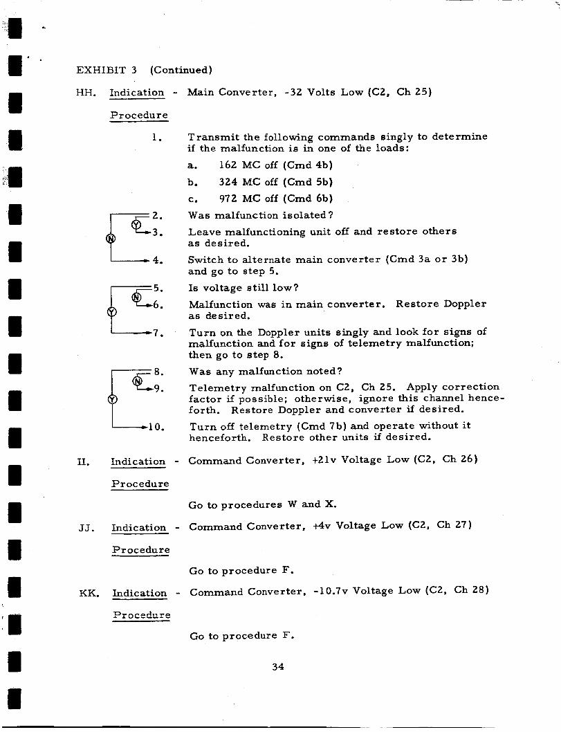
EXHIBIT 3 (Continued)
HH. Indication - Procedure
Main Converter, -32 Volts Low (C2, Ch 25)
1.
L 4.
-7.
11. Indication - Procedure
Transmit the following commands singly to determine if the malfunction is in one of the loads:
a. 162 MC off (Cmd 4b) b. 324 MC off (Cmd 5b) C. 972 MC off (Cmd 6b) W a s malfunction isolated?
Leave malfunctioning unit off and restore others as desired.
Switch to alternate main converter (Cmd 3a o r 3b) and go to step 5.
Is voltage still low?
Malfunction was in main converter. Restore Doppler as desired.
Turn on the Doppler units singly and look for signs of malfunction and for signs of telemetry malfunction; then go to step 8 .
W a s any malfunction noted?
Telemetry malfunction on C2, Ch 25. Apply correction factor if possible; otherwise, ignore this channel hence- forth. Restore Doppler and converter if desired.
Turn off telemetry (Cmd 7b) and operate without it henceforth. Restore other units if desired.
Command Converter, f21v Voltage Low (C2, Ch 26)
JJ. Indication - Procedure
Go to procedures W and X.
Command Converter, +4v Voltage Low (C2, Ch 27)
KK. Indication - D-,.-~,-I..~~ * rL V b b U U I "
Go to procedure F.
Command Converter, -10 .7~ Voltage Low (C2, Ch 28)
GO to procedure F.
34

be construed to mean any indication below the normal lower bound (in-
cluding zero) and "high" any indication above the normal upper bound.
The second of these concerns the "terminal commands." It is
not specified what these include, but they should consist of those com-
mands necessary to place the spacecraft in its desired f inal state.
They a r e utilized in these procedures when there is a distinct possi-
bility that a condition exists which may render the command subsystem
useless.
Finally, in some cases, the "safe" actions a r e called for before
These cases include those in which seri- any diagnosis is undertaken.
ous damage might be done immediately or over the period of the next
orbit if the spacecraft were to go out of range before the diagnostic was
completed.
mands or unloading a battery and then proceeding with the diagnosis.
Examples of this would be calling first f o r terminal com-
b. Optical Beacon and Associated Electronics
The following a re three "quick actions" which can be
The taken to correct the effects of malfunctions in the optical beacon.
Alternate Optical Logic (AOL) will be discussed later.
(1) "Switch memories" (i. e., switch in a redun-
dant memory and control unit) - Command
13a or 13b.
switched in will not operate until it has been
loaded from the ground.
Note that the memory which is
(2) "Switch oscillators" (Le., switch in a redun-
dant 5-megacycle oscillator a s the memory
timing source) - Command la or lb.
(3) "Switch oscillator oven heaters" (i. e., switch
in a redundant heater unit which controls the
temperature of the oven in which the oscil-
lators are located) - Command 2a or 2b.
Exhibit 4 presents the procedures to be followed in attempting to
overcome any indicated malfunctions.
35

EXHIBIT 4 - OPTICAL BEACON AND ASSOCIATED ELECTRONICS PROCEDURES
A. Indication
Indication may be:
a. b.
c.
d.
e. Extraneous flashing.
All 5 flash sequences inhibited.
All 7 flash sequences inhibited.
The inabiiity to read memory after loading. Presence of memory readout in place of normal telemetry a t all times.
Procedure
1. Switch to alternate memory (Cmd 13a o r 13b).
Is operation correct now? gx: Memory malfunction.
1. Double memory malfunction. Determine whether to use special programming or the AOL.
36
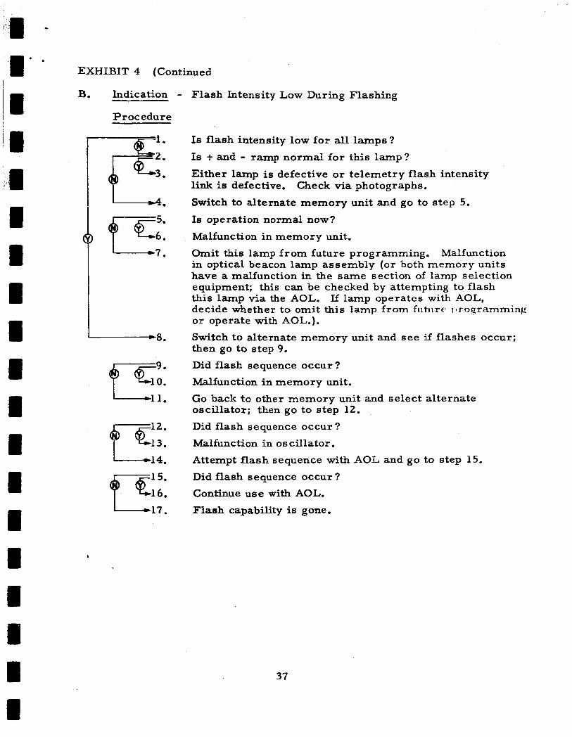
EXHIBIT 4 (Continued
B. Indication
Procedure
- Flash Intensity Low During Flashing
I 1 1.
gc:: I 1 4 .
k 1 7 .
Is flash intensity low for all lamps?
IS t and - ramp normdl €or this lamp?
Either lamp is defective or telemetry flash intensity link is defective.
Switch to alternate memory unit and go to step 5.
Is operation normal now?
Malfunction in memory unit.
Omit this lamp from future programming. Malfunction in optical beacon lamp assembly (or both memory units have a malfunction in the same section of lamp selection equipment; this can be checked by attempting to flash this lamp via the AOL. decide whether to omit this lamp from futitre rlrogramming or operate with AOL.). Switch to alternate memory unit and see if flashes occur; then go to s tep 9. Did flash sequence occur?
Malfunction in memory unit.
Go back to other memory unit and select alternate oscillator; then go to step 12.
Did flash sequence occur?
Malfunction in oscillator . Attempt flash sequence with AOL and go to step 15.
Did flash sequence occur ?
Continue u s e with AOL.
Flash capability is gone.
Check via photographs.
If lamp operates with AOL,
37
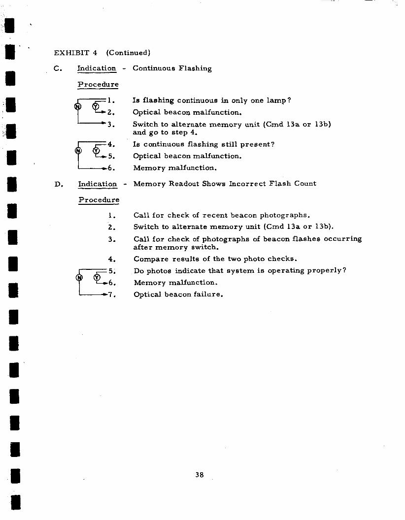
EXHIBIT 4 (Continued)
C. Indication - Procedure
Continuous Flashing
L 3 .
g c 4 : 1 - 6 .
Is flashing continuous in only one lamp?
Optical beacon malfunction.
Switch to alternate memory unit (Cmd 13a or 13b) and go to step 4.
Is continuous flashing still present?
Optical beacon malfunction.
Memory malfunction.
D. Indication - Memory Readout Shows Incorrect Flash Count
Procedure
1 .
2.
3.
4.
Call for check of recent beacon photographs.
Switch to alternate memory unit (Cmd 13a o r 13b).
Call for check of photographs of beacon flashes occurring after memory switch.
Compare results of the two photo checks.
Do photos indicate that system is operating properly?
Memory malfunction.
Optical beacon failure.
38
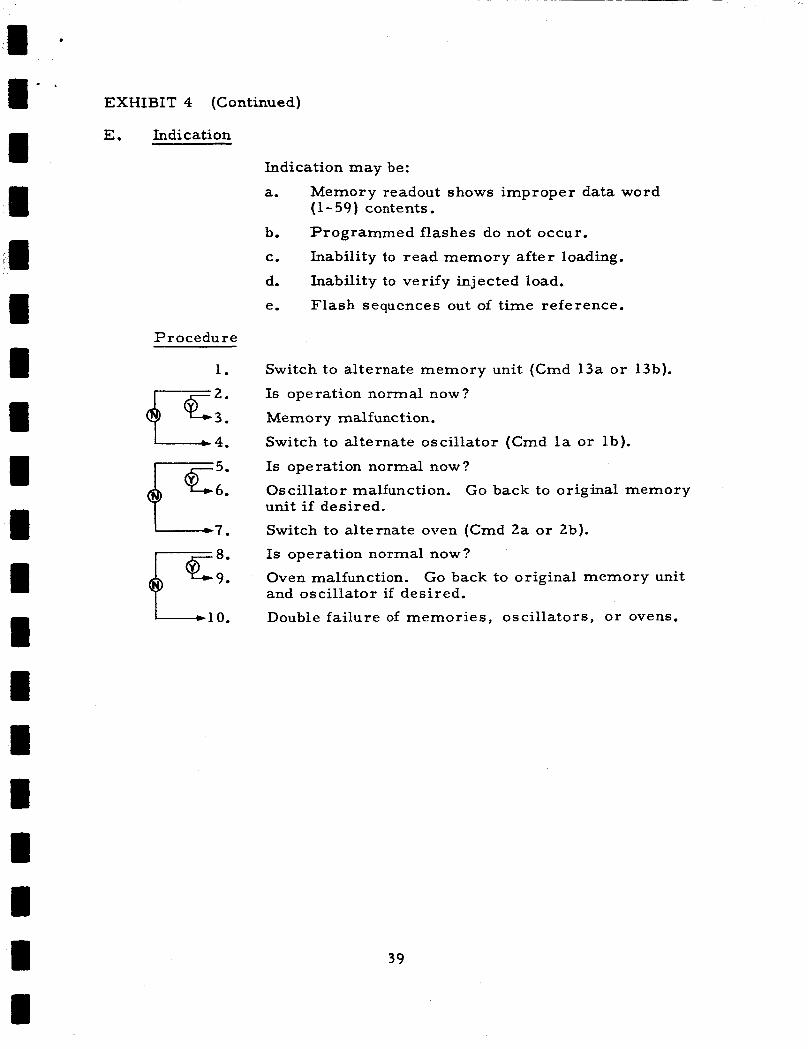
EXHIBIT 4 (Continued)
E. Indication
Indication may be:
a. Memory readout shows improper data word (1 - 59) contents.
Programmed flashes do not occur.
Inability to read memory after loading.
Inability to verify injected load.
Flash sequences out of time reference.
b.
c.
d.
e.
Procedure
1.
gc::
I 1 0.
Switch to alternate memory unit (Cmd 13a o r 13b).
Is operation normal now?
Memory malfunction.
Switch to alternate oscillator (Cmd la or lb).
Is operation normal now?
Oscillator malfunction. unit if desired.
Switch to alternate oven (Cmd 2a or 2b).
Is operation normal now?
Oven malfunction. and oscillator if desired.
Double failure of memories, oscillators, o r ovens.
Go back to original memory
Go back to original memory unit
39

If a l l attempts to correct the improper operation a r e unsucessful,
the failure is located either in the optical beacon, the optical power sup-
ply, or the interface between the optical beacon electronics and the AOL (which is the backup system f o r the memory and control unit).
failure is in the optical beacon, no corrective action is possible, except
that future memory programming might be able to minimize the effects
of the failure. If the failure is in the power supply, the procedures for
that subsystem should provide the necessary corrective action.
failure is in the interface, the AOL can probably still be used a s a backup
-system? The decision as to whether to employ the AOL should be based
on the degree of severity of the improper operation a s compared with
the limitations of the AOL. For example, i f the failure effect is the loss
of a l l memory-commanded flash capability, then the AOL would have to
be used; but if only one flash assembly is lost, proper programming
might be preferable to use of the AOL.
beacon ground stations which have mutual visibility of the spacecraft
with one of the STADAN stations or APL.
If the
If the
The AOL can only serve optical
If the discovery of improper operation has resulted in the switch-
ing in of a redundant memory and control unit, and a failure in this unit
is discovered, the decision as to what action is to be taken should be
based on the relative value to be gained from use of the two degraded
memory and control units and the AOL.
Indications of improper operation of the optical beacon experiment
can be found via the following:
0 Telemetry subcommutator channels which monitor the
flash assembly operation and flash intensity. (Contin-
uous flashing, extraneous flashing, absent flash se-
quences, inoperative flash assemblies, etc., can be
discovered from this source.)
'Only four of the 30 applicable failure effects involve loss of the AOL.
40

i
Inspection of photographs taken of flash sequences
by ground cameras.
flash sequences which a r e out of time reference,
and sequences having low intensity can be dis-
covered from this source.)
Incorrect number in the flash count word during
the memory preload readout. (Absent flash se-
quences and extraneous flash sequences can be
discovered from this source.)
Incorrect numbers in the 59 data words during
the memory readout.
e r ro r s resulting in many failure effects can be
discovered from this source.)
Inability to properly load memory.
Inability to read o r verify memory after loading.
Presence of memory readout in place of normal
telemetry a t all times.
c. Thermal Control Subsystem
(1) Analysis Inputs
(Absent flash sequences,
(Memory data handling
The inputs that a r e available for a thermal
analysis a r e telemetry data from commutator 1, commutator 2 , and
telltale register 3. The telemetry data from the commutators repre-
sent temperatures measured by thermistors, while the telltale regis-
ter provides indication of the state of battery thermostats. Exhibit 5
shows the location of the components which a r e monitored by the te-
lemetry data.
(2) Analysis Outputs
The primary objective of this analysis is to
provide a method by which certain telemetry data may be monitored,
and thus to provide a means of ameliorating critical thermal condi- L 2 - L A u I i S if they sheiild arise. S~~IZC the e q - i p m e ~ ~ t being ~ ~ ~ ~ i t ~ r p c ? is
41

C1
Telltale Register 3
C h l : Optical Manual Dump On/Off
Ch2:
Ch3:
G i A : Optical Au:~rr~at ic 2 c r . p Sr.!Cif
ChS: Transponder Manual Dump On/Off
Ch6: Transponder Automatic Dump Enable On/Off
Cb7: Transponder Automatic Dump On/Off
Optical Automatic Dump Enable On/Off
Optical Automatic Dump Enable On/Off
Commutator (C) 2, Channel (Ch) 8: Transponder Battery Tempera ture Ch8: Transponder Automatic Dump Enable On/Off
2 . Chb: Main Battery Temperature
CZ. Ch33: SECOR Receiver
, Ch15: SECOR Transmi t te r
C1. Ch32: Quadrant I Book
Q C1. Ch16: Optical Battery Temperature
I Q C1. Ch16: Optical Battery
Temperature
I
Ch34:
Ch35:
Ch33:
Ch35:
-CL.
Quadrant III Book Ternpprature
Oscillatur D e w a r Ternperdturr
Quadrant I1 Book Temperature
Range and Range Rate Trans- ponder Tempera ture
ChZ9: 17 Solar Aspect Drtrctoi Temperature and Solar Scr enc e Temperature
EXHIBIT 5 - LOCATION OF THERMAL CONTROL INDICATORS FOR TELEMETRY
42

1' - I I 4 1 I M I I M I I I I I I M I
electronic in nature, most failures will occur in an abrupt manner in
comparison to the 24-second t ime period between temperature readings
for one channel.
e r s that telemetry is generally monitored only over APL. mum telemetry read-out time is approximately 20 minutes out of each
orbit.
The abruptness is even more acute when one consid-
The maxi-
The cause of these failures may be ( 1 ) nonadjustment to circuit or
environmental conditions, (2) random-type failure, o r ( 3 ) wearout through
use.
preliminary engine e r ing wo rk.
The first type of failure will, for the most part, be taken care of in
The purpose of this analysis will then be to determine what equip-
ment to turn "off" that normally would be "on," or vice versa, to achieve
a thermal condition that will not further degrade the spacecraft electronic
systems. Exhibit 6 illustrates the basic philosophy that has been taken to
arrive at the diagnostic routine. It shows that there is an operating ''up-
per temperature limit" a t which parts in a component cannot be expected
to perform within circuit-defined specifications.
operating upper temperature limit" which may be determined by calcu-
lations and tests simulating operation of the spacecraft in view of solar
radiation. And, in like manner, there is an "expected operating upper
temperature limit" which may be determined by calculations and tests
simulating operation of the spacecraft in eclipse of solar radiation.
There is a "lower temperature limit" a t which certain parts will not
function within specification; thus, the components containing these
parts must be kept above this temperature.
There is an "expected
There a re also a pair of
expected operating lower temperature limits" corresponding to the sun n
and eclipse conditions.
tween "upper temperature limit" and "expected operating upper tem-
perature limit" is, in fact, a measure of the margin of safety of the
design.
It may be pointed out that the relationship be-
The thermal s t ress is a function of the time rate of change of
temperature. Therefore, the time rate of change of temperature of
43

a --
I' .
II I II 1 i I I I I I 1 1 I I I I 1
C 1 ?
Is
CI
3 m k 3 CI ld k e, a
c-c E m
U k e, '2 a
Is r 2
W k 1 U Id &
...I U
m a,
0" a a 0 0) F-c
& u m m R R a X 3 w
E U
e, m a V w .* rl
I I c)
2 ri 0) k 1 Id k W a
f-+ k m a a 3
CI
E 8
F
8
z
.d U
Id k m
a 0)
U m a
U
'~~ Id
k V 6 u
I , a n l l r n
I I l a
!i Y -2 Is
c)
a, I4
3 CI ld k e, a m F-c
3
E
k 9)
s ?
8
k
.d c, (d k m
73 m U W
U
w
m m .4 d
V w I U
-2 s e, k 3 c) ld k 6
8 e,
c-c
0) k 1 U Id k a,
2 .d U (d k a,
8 8 m
F-c a m V m R X w 2
k m
4J
m- -0 c 0-
I 1
N- I 1
I 1
I 1 I
I 1 I t .- I - I 1 I I
I
I 1 1 t
I I 1
1 1
E I I c-c I I 1
I 1 I I 1
I I 1 I 1 I
44

f
each temperature telemetry point will be monitored and, if this value
should exceed a predetermined maximum value, an indication of im- pending trouble w i l l be signaled. The maximum value of the time rate
of change of temperature for each temperature point can be determined
from thermal stress considerations for a l l parts in the spacecraft.
Transient thermal testing and/or analytical modeling will be required
to determine these values.
for n multiples of an orbital period will be estimated by the equation
Ti + (dT/dt)nAt = Tn , where t is equal to elapsed time, T is tem-
perature, and Ti is the most recent temperature reading. The value
of T in this extrapolation is the average temperature recorded during
a single pass per telemetry point.
a given pass a re expected to be small. It is suggested that n take on
integer values from 1 to 10.
In addition, the expected temperature (T,)
Variations in temperature during
Exhibit 7 represents a format for recording the pertinent limiting
values of temperature and time rate of change of temperature for the
pertinent subcommutator channels.
tion to specify these values.
life-time a re involved in setting such values.
essary to relate the monitored temperatures with the temperatures of
all critical parts in the spacecraft under steady- state and transient con-
ditions. Thus, exercise of a computerized thermal analytical model
and/or thermal vacuum tests a r e required to establish these relationships.
PRC, a t present, is not in a posi-
Considerations of current design and part
Furthermore, it is nec-
Exhibit 8 presents a l ist of the telltale telemetry points associated
with thermal control.
Exhibit 9 is a tabular presentation of the diagnostic routine.
The decision-action chart shown in Exhibit 10 provides remedies,
where they exist, based on the results of the diagnostic routine.
decision-action chart provides a remedy for abnormal temperature con-
The
ditions for certain components that can be controlled from the ground.
d. Command Subsystem
n l 3 1 ne ~ ~ i i ~ i i ~ i i i i si,i%sy~stei~ criisiets of two rediiiid~iit
receivers, two redundant logic units, and a matrix. Since the receivers
45

a II
I 1
46

EXHIBIT 8 - TELLTALE TEMPERATURE CHANNELS
Telltale Register 3 , Commutator 1, Channel 29 Tel l ta le Tell tale Indica tion Number High
1 Optical Manual Dump O F F
3 Optical Automatic Dump Enable O F F
4 Optical Automatic Dump O F F
5 Transponder Manual Dump O F F
6 Transponder Automatic Dump Enable OFF
7 Transponder Automatic Dump O F F
8 Transponder Automatic Dump Enable O F F
47
Optical Automatic Dump Enable ON
Optical Automatic Dump ON
Transponder Manual Dump ON
Transponder Automatic Dump Enable ON
Transponder Automatic Dump ON
Transponder Automatic Dump Enable ON

1 4
0 Y
a m m e L,
6
. . ry n i
V 0 m
L 4 2 rd
m
C + .4
E-
C E-
& G c' m
48

u z 0
c) 4
0
u w
F:
d H
';?
n c w B v3 * v3 E9 5 v3 4 0 cr; E z 0 u
4 & w 5: E I
0 4
B E9
X w
H
2
PI s 0 c
1 r 0
C 4 Y
0 .d
-
m 9 0
h Y
; ::
e I - 0
Y
0 - n m 7-4
E U
3 W
i. 0
I ir
s - 0 Y
W
.", B C
c M B 0 "
49
F
I: 0
.I
C .- s;

are far more reliable than the digital sections, attention was concentrated
on the failure states that can occur in a logic unit o r the matrix.
since in this case single failures appear more likely than multiple failures,
the condition of both logic units being in failure states was not specifically
considered. The possibility, however, of such an occurrence was pointed out where applicable and should be discussed at this point.
Also,
When a command is transmitted, one of the following four things
wi!l occur:
(1) (2)
(3)
The command is executed correctly. The command is not executed.
One or more extra commands a r e executed along with the transmitted one.
The wrong command is executed. (4) Occurrences (2) and (3) can be caused by failure(s) in either a logic unit
o r the matrix.
or tone-oriented. Thus, multi-failure states can exist in which a given
row, for example, cannot be selected from logic unit 1 and a given column
cannot be selected from logic unit 2.
is actually lost, i. e., the one at the intersection of the specified row and
column.
it might be concluded that the entire command subsystem was nonoperable.
Most of these possible failures a r e either row-, column-,
In this example, only one command
If this happened to be the command one was attempting to execute,
In cases like this, two approaches a r e possible to determine the
extent of the failure. "Trouble-shooting" can be done, i. e., commands
can be transmitted solely for the purpose of determining which ones a r e
available and from which logic unit.
only those commands called for by normal operation and to record
whether they were executed and, if so, by which logic unit.
some period, the nature of the failure state could be deduced from the
records. The decision as to which approach to use wculd have to be based
on the importance of knowing the exact state of the subsystem and the risk
of transmitting a command during trouble -shooting that the failure state
would make impossible to retract.
Another approach is to transmit
Thus, after
Ey-.&i?-& 1 1 pr=f?=nts ?, prcce.ll.rP, fsr =&*.ring at c.,e c=rrec9:;-...=
action for the various states that can occur. The failure state numbers
5 0
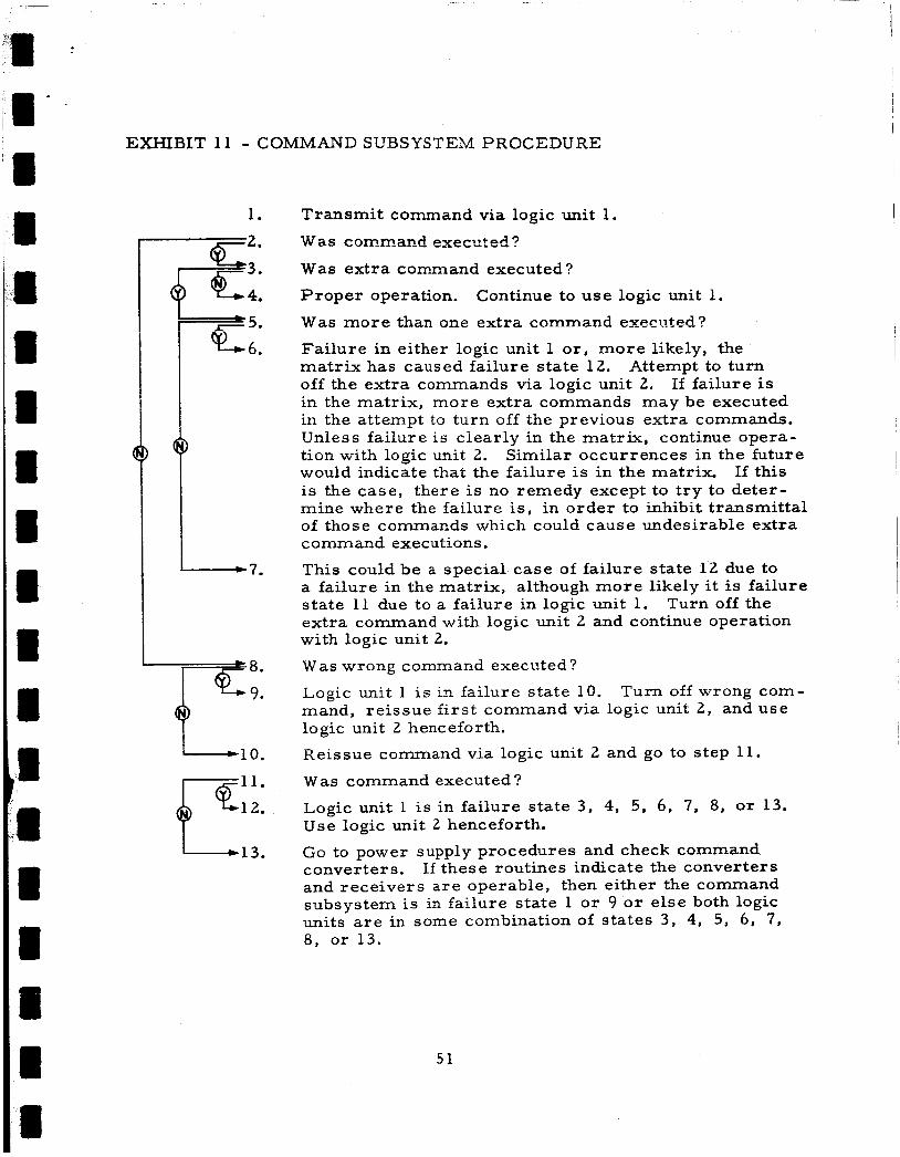
EXHIBIT 11 - COMMAND SUBSYSTEM PROCEDURE
1.
-7.
"L,,. 1 - 1 3 .
Transmit command via logic unit 1.
W a s cornoxand executeti?
Was extra command executed?
Proper operation. Continue to use logic unit 1.
Was more than one extra command executed?
Failure in either logic unit 1 or , more likely, the matrix has caused failure state 12. off the extra commands via logic unit 2. in the matrix, more extra commands may be executed in the attempt to turn off the previous extra commands. Unless failure is clearly in the matrix, continue opera- tion with logic unit 2. would indicate that the failure is in the ma t r ix If this is the case, there is no remedy except to try to deter- mine where the failure i s , in order to inhibit transmittal of those commands which could cause undesirable extra command executions.
This could be a special case of failure state 12 due to a failure in the matrix, although more likely it is failure state 11 due to a failure in logic unit 1. extra command with logic unit 2 and continue operation with logic unit 2.
Was wrong command executed?
Logic unit 1 i s in failure state 10. mand, reissue first command via logic unit 2, and use logic unit 2 henceforth.
Reissue command via logic unit 2 and go to step 11.
Was command executed ?
Logic unit 1 is in failure state 3, 4, 5, 6, 7, 8, or 13. Use logic unit 2 henceforth.
Go to power supply procedures and check command converters. If these routines indicate the converters and receivers are operable, then either the command subsystem is in failure state 1 o r 9 o r else both logic units a r e in some combination of states 3, 4, 5, 6, 7, 8, or 13.
Attempt to turn If failure is
Similar occurrences in the future
Turn off the
Turn off wrong com-
51

shown in Exhibit 11 can be found in the failure mode and effect analysis,
Appendix B, TAM 106-1.
Not shown in the exhibit but implicit in each action is an indication
check.
telemetry.
experiment response indications.
(i. e., lloff" o r "on") should be known prior to command transmission and checked again after command transmission. This is necessary not oniy
to learn whether the command was executed, but also discover whether
an extra command or a wrong command was executed.
For most commands, there is a telltale indication available from
In some cases, there will be other telemetry indications and/or
The status of each command function
e. Telemetry Subsystem
No corrective action is possible in the event of telemetry
failures other than turning off the telemetry subsystem i f it is causing undue
power drain.
used to determine if this is the case. If possible, the power supply subsystem routines should be
That aspect of the telemetry subsystem given most consideration in
this analysis was the nature of its failure states. The failure mode and
effect analysis revealed 20 major failure states, as listed in Exhibit 12.
In all states except state 1, some valid data will be transmitted. In order
to make use of the transmitted data, one must be able to discern which of
the data a r e valid and which a r e invalid. This should be fairly easily
discernible for all but the following states: State 3 (lose 60 channels)
State 4 (lose 56 channels) State 12 (lose 1 commutated channel)
State 13 (lose 1 subcommutated channel)
State 14 (lose 5 telltale (TT) bits)
State 15 ( lose 1 TT bit)
States 3 (lose 60 channels) and 4 (lose 56 channels) represent such
major losses that, should one of them occur, it might be thought that both
commutators were lost. In state 3, only five specific channels will be trans-
mitted by each Commutator, for a total of 10 channels.
wil l be transmitted by each commutator for a total of 14 channels in state 4.
Seven channels
52

EXHIBIT 12 - GEOS TELEMETRY SUBSYSTEM FAILURE STATES
Failure State
1
2 3
4
5
6 6a
6b
7
8
8a
8b
9 10
1 O a
1 Ob
1 oc 11
12
13
13a
13b
14
14a
14b
14c
15
15a
15b
15c
Loss
All telemetry
Both commutators
60 channels (30 from each commutator)
56 channels (28 from each commutator)
Commutator 2 and memory readout
Any commutator
Commutator 1
Commutator 2
Both subcommutators
Any subcommutator
Subcommutator 1
Subcommutator 2
All TT registers
Any TT register
TT register 1
TT register 2
TT register 3 7 commutated channels
1 commutated channel
Any subcommutated channel
1 subcornmutated channel, subcornmutator 1
1 subcommutated channel, subcommutator 2
Any 5 TT bits, TT register
5 TT bits, T T register 1
5 TT bits, T T register 2
5 TT bits, TT register 3
Any 1 TT bit, TT register
1 TT bit, TT register 1
1 TT bit, TT register 2
1 TT bit, TT register 3
53

EXHIBIT 12 (Continued)
Failure State
16 16a
1 6b 16c 17 18 19 20
Loss
Any flash intensity information
Flash intensity information and flash count to memory
Fiash intensity information
2, 3, o r 4 flash intensity information
Memory readout
Time marker
sync All temperature indications
5 4
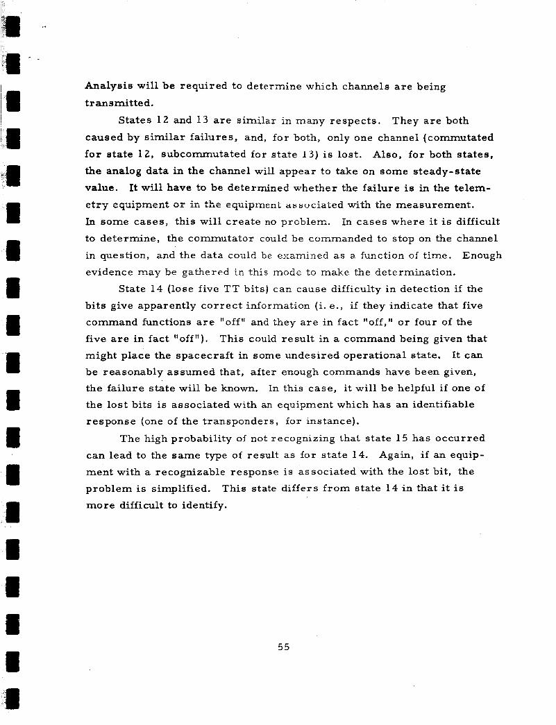
Analysis will be required to determine which channels a re being
transmitted.
States 12 and 13 a re similar in many respects. They are both
caused by similar failures, and, for both, only one channel (commutated
for state 12, subcornmutated for state 1 3 ) is lost. Also, for both states,
the analog data in the channel will appear to take on some steady-state
value. It will have to be determined whether the failure is in the telem- cf4-'c C L e l j u + p A A L C ; I i L in the eqiiipiiicni associated with the measurement.
In some cases, this will create no problem. In cases where it is difficult
to determine, the commutator could be commanded to stop on the channel
in question, and the data could be examined as a function of time.
evidence may be gathered i n this mode to make the determination.
Enough
State 14 (lose five TT bits) can cause difficulty in detection i f the
bits give apparently correct information (i. e., if they indicate that five
command functions a re "off" and they are in fact "off," or four of the
five a re in fact "off").
might place the spacecraft in some undesired operational state.
be reasonably assumed that, a f t e r enough commands have been given,
the failure state will be known.
the lost bits is associated with an equipment which has an identifiable
response (one of the transponders, for instance).
This could result in a command being given that It can
In this case, it will be helpful i f one of
The high probability of not recognizing that state 15 has occurred
Again, i f an equip- can lead to the same type of result as fo r state 14.
ment with a recognizable response is associated with the lost bit, the
problem is simplified.
more difficult to identify.
This state differs from state 14 in that it is
55
I 1 II
APPENDIX A
APPLICATION O F DECISION THEORY TO THE OPERATIONAL ANALYSIS OF GEOS
The main body of this report has been concerned with possible
malfunctions of the spacecraft, their discovery, and the appropriate
corrective actions to be taken. In general, the assumption is made that
the telemetry indications as received on the ground a r e correct.
ever, telemetry equipment can fail, and i t may fail in such a way that
false conclusions a re drawn with respect to the spacecraft. Thus, some
uncertainty about the in-orbit state of the spacecraft results, due to the
questionable validity of the information sent back to earth. An unrecog-
nized failure in telemetry could lead to a wrong corrective action deci-
sion and possibly to severe unwarranted satellite degradation.
How-
The problem considered in this appendix is to determine the best
possible corrective action (in t e rms of least satellite degradation or loss)
on the basis of possibly erroneous telemetry indications. The solution to 1 . this problem is naturally formulated in terms of decision theory.
To illustrate the application of decision theory to this problem, a
simplified example i s presented below that attempts to come as close to
the real-life problems as clarity of presentation will allow.
meant to be taken as a directly applicable statement about the GEOS space-
craft. In the power supply diagnostic routine, there a re several items that
deal with telemetry points associated with the command converter.
the command system is a vital part of the spacecraft, this example will be
concerned with the uncertainty in the state of the command converters,
first when only a telemetry channel directly related to the converter is observed, and again when additional telemetry channels a re observed
for corroborating evidence.
It is not
Since
'Chernoff, H., and L. E. Moss , Elementary Decision Theory (New Y o r k : John Wilev and Sons, Inc., 1959).
m m
56

4 - - The true condition of an in-orbit spacecraft is called a state of
nature.
failed, or degraded states of par t o r all of the spacecraft.
bology used for k states of nature i s 8, , 8, , . . . , 6, . actions, denoted by al , a2 , a
spacecraft by commands.
A state of nature could correspond to the unfailed, completely
The syrn-
Possible
a r e represented in the GEOS 3 * * ’ * * “j
Using the above nomenclature, the problem is stated a s follows:
8 , = Command converter in completely unfailed state.
8, = Command converter is severely degraded state.
a = Ignore telemetry data and proceed normally with 1
a2
L
operations.
= Issue no further command for any subsystem until status can be fully assessed; send terminal commands which leave on or turn on Doppler and SECOR and turn off all other active experiments.
For each action that is taken, there i s an expected loss depending
This loss is measured according upon the true state of the spacecraft.
to the value of the spacecraft experiments.
pected value relative to the other experiments which could be los t i f it
is not functioning properly.
the experiments a re as follows:
Each experiment has an ex-
The relative values, V , used for each of
Optical beacon: V1 = 5/12
Doppler: V2 = 4/12
SECOR: v3 = 2/12
Range/range rate: V4 = 1/12
If the spacecraft is in a completely unfailed state, O1 , and the
al , then the expected loss is operator takes the appropriate action,
zero. However, if the spacecraft is in state el and action a is taken
then the optical beacon and range/range rate experiments a r e turned off
and the loss is V1 t V4 = 1/2 . When the command converter is severe
degraded, state 8, , the worst action which can be taken is to proceed
as though nothing has happened, action a * thus the loss in this worst
case is assumed to be 1. However, i f action a the correct action,
is taken, the loss should be s o m e intermediate value which reflects both the degraded state and the performance of the correct action. This loss
2
1 ’
2 ’
57
Y

i s taken to be 1/2.
action a when the spacecraft is in state 8 , is summarized in the
following table:
&(6,a) , the expected loss due to the taking of
Action State of Nature 8
82 1 1 p 2
Decision theory assumes that the state of nature is not known. If
it were known, then the correct action would always be taken. measuring device responses, in this case telemetry data and experiment
data, a r e employed as indicators of the state of nature.
sponse of the measuring device by x and the probability density function of x under a particular state of nature 8 by f(&) .
Therefore,
Denote the re -
For telemetry data which indicates whether certain equipment is
in the or "off" state, the probability distribution becomes a dis-
crete one, with all the probability located at the two telemetry values
correqponding to the tton" and "off" states.
in character.
bility distribution is involved.
from reliability models of the telemetry subsystem and/or the
experiments.
Such information is binary
In the case of analog telemetry data, the complete proba-
These distributions may be predicted
For a single telemetry channel, possible observations were assumed
to be:
x1 = Telemetry reading neither zero nor full scale.
x2 = Telemetry reading zero.
x3 = Telemetry reading full scale.
In the reliability analysis of the telemetry subsystem, the probability
of losing one commutated channel in a 1 -year period was found to be 0.0082.
The following table contains the assumed probabilities of obtaining the telem-
etry reading x given state of nature 8 .
58

Observation SI f(x/e) 1 State of X
Nature 8
0.9918 01
2 x3 X
0.0082 0
Since f (x3/e) = 0 , example.
x can be disregarded for the remainder of this 3
The connection between the observation x and the action a is
provided by a strategy.
taken in response to the measuring device.
possible strategies when only one telemetry channel is observed is
given below.
Strategies consist of specific actions to be
A tabular presentation of
2 s3 s1 S Nature 8
0 0.0041 0.50
1 0.5 1 81
82
x1
"4
0.5
0.5
I al I al I a2 I a2
Associated with each strategy and each state of nature is an expected
loss L(e, s) . This loss is dependent upon the probability of observing x
given 6 in the following manner:
= 0.9918(0) + (0.0082)(0.5) = 0.0041
The expected loss L(8, s) for each strategy is presented below:
59

I - 4 ’ -
In order to eelect the appropriate strategy, one may choose that
strategy which minimizes the weighted average of expected loss. This is the so-called Bayes strategy and is based on the a priori probabilities
of the two states of nature p(e ) and p(e2) . is thus the one which minimizes:
The appropriate strategy 1
The a priori state probabilities for the command converter are
estimated to be:
based on a conventional failure mode and effects analysis and reliability
model of the cormnand converters.
. Therefore:
L(s l ) = 0.000029
L(s2) = 0.0041
L(s3) = 0.50
L(s4) = 0.5
and strategy s1 is best (i. e., continue operating normally if only one
telemetry cornmutator channel indicates a malfunction). This result, which is somewhat contrary to intuition, is obtained
because the probability of a single commutator channel failure is much
greater than the probability of command converter failure.
This example, thus far being based on a single channel of telemetry
information, is quite artificial in that additional evidence will in fact be
available for determining the true state of nature and therefore arriving
60

at the appropriate corrective action strategy.
of corroborating evidence, three telemetry channels which indicate com-
mand converter malfunction a r e assumed to be available.
nature, actions, and lose of expected value a r e unchanged.
As an example of the effect
The states of
The observation from the measuring device m a y DOW be described -.
as a vector x = (Xi l J xiZ, xi3), where
i = 1, telemetry reading neither zero nor full scale,
z - - 2, telemetry readbig zero, i = 3, telemetry reading full scale,
and the probabilities f(x../e) , where j = 1, 2, 3 (designating telemetry
channels) a r e the following: 1J
Possible Observations -
1j X
Nature 8
0.9918 0
61
$2
x2j x3 j
0.0082 0
1 0
where
n = the number of channels with reading i = 1, 2 . X. 1j
The following table of probabilities, f(</e ) , results:
61
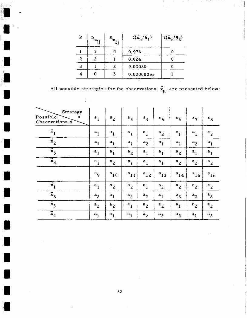
1 3 0 I 0.976 I 0 2 3
2 1 0.024 0 f 2 0.00020 I O
1
1 s 2 S
- 1 a
a 1 a
a
1 a
a
"1 -
' 6 I
4 s 5 S
1 a a a
a a 2 1
13 S s 9
1 a2 1 a2 a 2 a a "1 - "2 a2 al a2 I a2 al - "3 a2 =2 1 a2 a2
1 al "4
a
a 2 a 2 a 1 a
1 1 2 1 1 "2
62
1 al
'14
- 1
1
a
a x3
"4
2 a
2 a 1 a
a 2
1
a
a
1 a
a2 1 I al a2
a2
al
2 a
s 7 I S8
a 1 j a2
a2 j al
al I al
2 a2 1 a
15 1 '16
a l a 2 1 2 + a2 I a2 a2 1 a2
al I a2

The expected loss L(9, a ) for each strategy is:
8, 8,
0.012. 0.49 0.50 0.012 0.49 0.50 0.50 f 0.5
1 1 1 0.5 0.5 0.5 1 10.5 f
The weighted average of expected losses obtained under the a priori
probabilities given in the previous example, are:
If these losses a r e ordered and the strategies studied, it can be
seen that in general the strategies which require the least corroborating
evidence before action a i s taken (i. e., send terminal commands) have
the greatest loss. Thus, a s would be expected, the more corroborating
evidence available, the less value of the spacecraft is lost.
which takes action a
the best strategy in this case.
This, of course, is precisely the strategy that would be taken on
2
Strategy s2 , unless all three channels give a zero reading, is 1
an intuitive basis. Thus, when telemetry failure is assumed to occur
on a channel-by-channel basis, the application of decision theory does
not result in conclusions beyond what would be obtained by intuitive con - siderations. By using the previously given diagnostic routines and
6 3

decision-action charts, a failure can be isolated and the appropriate
action taken.
single channel and therefore taking a wrong action is inconsequential
if corroborating evidence is sought before taking action on the basis of
a s ingle telemetry channel readi~g .
GEOS A make corroborating evidence quite readily available.
agnostic routines and decision-action charts presented in this report
reflect the philosophy of seeking corrohnratiye evidence.
of decision theory to GEOS operational reliability analysis in the grosser
situation where there is substantial loss of telemetry and a concomitant
increase in uncertainty is expected to yield results which a re nonintuitive.
This application is presently under consideration.
The problem of obtaining incorrect telemetry data on a
~ f ; e telemetry assignments for
The di-
The a~pliczticn
64

APPENDIX B
COMMAND LIST
GEOS A Command Sys tem Functions and Command Tone Assignments
l a
l b
2a
2b
3a
3b
4a
4b
5a 5b
6a
6b 7a
7b
8a
8b
9a 9b
1 O a
10b
1 la
l l b
12a
12b
Note:
Oscil lator 1 Select
Oscil lator 2 Select
Oscil lator Oven 1 ON
osc i l la tor Oven 2 ON
Main Converter 1 ON
Main Converter 2 ON
162 MC Transmi t te r ON
162 MC Transmi t t e r OFF
324 MC Transmi t te r ON
324 MC Transmi t te r OFF
972 MC Transmi t te r ON
972 MC Transmi t te r O F F
Telemeter System ON
Telemeter System OFF
TM Function F M / P M ON
TM Function F M / P M O F F
Vector Magnetometer ON Vector Magnetometer O F F
Solar Only ON Solar Only O F F
Commutator 1 Hold ON
Commutator 1 Hold OFF
Commutator 2 Hold ON
Commutator 2 Hold OFF
Command Tones
DDD
DDB
DDE
DDC
EED
E E B
EEC
CCB CCD I ccc CCE t BBD
BBB
BBE
BBC
DED
DEB
DEE
DEC
DC D
DC B
DCE
DC C
Telltale Indication
Number" State
B- 1 High
B- 1 Low
A- 1 High
A- 1 Low
A-2 High
A-2 Low
See channel 30, commutator 2
See channel 31, commutator 2
See channel 32, commutator 2
A- 3
A- 3
A-4
A-4
B-2
B-2
A- 5
A-5
High
Low
High
Low
High
Low
High
Low
(1) A corresponds t o telltale r eg i s t e r 1; B corresponds to tell tale reg is te r 2; C corresponds to tell tale reg is te r 3.
65

4 ' ' Command
13a
13b
14a 14b 15a 15b
16a 16b 17a
17b
18a
18b
19a 19b 2 O a
2 O b 2 l a l (2 1
2 lbl
2 la2
22bl
22a2
22b2
2 3a
23b
24a
Command Telltale Indication Command Function Tones Number State
Memory Select: 1 ON, 2 O F F DBD A-6 High
Memory Select: 1 OFF, 2 ON DBB A- 6 Low Boom Squib Enable OFF EDD B- 3 High
Boom Squib Enable ON EDB B- 3 Low
Boom Squib Fire and 3 . 9 ~ Zener IN BDE B-4 Low B-4 High (1) Boom Safe and 4 . 7 ~ Zener IN
Boom Bypass ON DBE A - 7 High
BDC
Boom Bypass O F F DBC A-7 Low
Boom Out ECD A-8 Low
Boom In Boom Motor ON
Boom Motor O F F
162 Phase Modulator ON
162 Phase Modulator O F F
324 Phase Modulator ON
324 Phase Modulator OFF
Optical Power Dump OFF
Optical Manual ON: Automatic O F F
Optical Manual OFF: Automatic ON
Optical Manual ON: Automatic ON
Transponder Power Dump OFF
Transponder Manual ON: Automatic O F F Transponder Manual OFF: Automatic ON Transponder Manual ON: Automatic ON Range Transponder ON and Voltage Sensing Switch Rese t
Range Transponder OFF
Range Transponder Manual
ECB
EC E
ECC
EBD
E B B
CDD
CDB
CDE
CDC
CDE
CDC
CED
CEB
CED
CEB
C BE
C BC
CEE
A-8 High
A-9 Low A-9 High
B- 5 High
B-5 Low
B- 6 High
B-6 Low
C - 1:C-2,3 High:High
C- 1:C-2,3 Low:High
C- l:C-2,3High:Low
c- 1:c-2,3 L0w:Low
C - 5 : C- 6,8 High:Hig h
C - 5:C- 6,8 Low :High
C-5 :C-6,8 High:Low
C- 5 :C - 6,8 LOW:LOW
B- 7 High
B- 7 Low
B-10 High
Notes : (1) B-4 is high only when B-3 is low and the spacecraft and booster a r e separated.
(2) Both commands 2 1 and 22 a r e 4-s ta te sequential commands.
66

I I ' Command
24b 2 5a
25b 2 6a 26b 2 7a
2 7b
2 8a
2 8b
2 9a
29b
3 Oa
3 Ob
3 l a
3 l b
32a
32b
Command Telltale Indication Command Function Tones Number State
Range Transponder Normal
R/RR Transponder ON and Voltage Sensing Switch Res et
R/RR Transponder O F F
R /RR Transponder Manual
R/RR Transponder Normal
AOL 1 S ta r t F l a sh
AOL 1 F la sh OFF
AOL 2 S ta r t F lash
AOL 2 F la sh O F F
Memory Load Star t
Memory Load Telltale R e s e t
Memory Converter 2 ON
Memory Converter 1 ON
Voltage Sensing Cutoff Overr ide ON
Voltage Sensing Cutoff Overr ide O F F
TM Time Marker ON
TM Time Marker OFF
67
CEC
EDE
EDC CBD
CBB
BEE
BEC
BCE
BCC
E BE
E BC BDD
BD B
BED
BE B
BC D
BC B
B-10 Low
B-8:B-9 High:Low
5-8:E-9 Low:High
B-11
B-11
R- 12
B- 12
B-13
B- 13
A- 12
A- 12
A - 13
A-13
B- 14
B- 14
B- 15
B- 15
High
Low
High
Low
High
Low
High
Low
Low
High
Low
High
High
Low

APPENDIX C
TELEMETRY LIST
Commutator 1
Channel
1
2
3
4 5
6
7
8
9
10
11
12 13
14
15
16 17
18
19
Telemet ry Assignment
t 0 . 2 5 ~ Cal ibrate
Ov Calibrate
- 0 . 2 5 ~ Cal ibrate
Main Solar Curren t
Main Battery Curren t
Main Converter Input Curren t
Command Converter Input Cur r en t
Transponder Solar Curren t
Transponder Battery Curren t
6 Mil Glass N on P
6 Mil Glass P on N
X Magnetometer Voltage
Y Magnetometer Voltage
Z Magnetometer Voltage
Range Trans ponder Transmi t te r Temperature
Channel Te lemet ry Assignment
20 Memory Converter Input
2 1 Memory Converter +10.7
22 Memory Converter t4.0
23 Memory Converter -10.7
24 Main Converter t 2 1 v Curren t
25 Main Converter -32v Curren t
26 Command Converter t 21v
Current
Voltage
Voltage
Voltage
Curren t
27 Command Receiver 1 AGC
28 Command Receiver 2 AGC
29 Telltale Regis ter 3
30 F la sh Assembly 1 Temperature
31 F la sh Assembly 4 Temperature
32 Quadrant 1 Book Temperature
33 Quadrant 2 Book Temperature
3 4 Quadrant 3 Book Temperature
Optical Battery Temperature 35 Telltale Regis ter 1 36 t 0 . 2 5 ~ Calibrate
Subcommutator 1 /Optical 37 t 0 . 2 5 ~ Calibrate 38 t 0 . 2 5 ~ Calibrate System Current
Optical Battery Current
Oscil lator Dewar Temperature
68

Commutator 2
Channel Telemetry - Assignment Channel Telemetry Assignment - 1
2
3 4
5 6 7
8
9 10
11
12
13
14
15
16 17
18
19
t 0 . 2 5 ~ Calibrate
Ov Calibrate
- 0.25~ Calibrate Main Bus Voltage
Main Battery Voltage
Main Battery Temperature
Command Converter Input Voltage
Transponder Battery Temperature
Transponder Bus Voltage
Solar Calibrate
Linear Solar Attitude Detector (SAD)
+Z SAD
+X SAD
+Y SAD
-X SAD
- Y SAD
Telltale Register 2
Subcommutator 2 /Optical Battery Voltage
SECOR Regulator Output Voltage
20
2 1
22
23
24
25
26
27
28
2 9
30
31
32
33
34
35
36
37
38
SECOR Plate Current
SECOR 250 Voltage
Range and Range R a t e Receiver Output
Range and Range Rate R F Power Detector
Oscillator Regulator Voltage
Main Converter -32 Voltage
Command Converter +21 Voltage
Command Converter +4.0 Voltage
Command Converter - 10.7 Voltage
+Z SAD Temperature and Solar Science Temperature
162 MC R F Power Detector
324 MC R F Power Detector
972 MC R F Power Detector
SEC OR R e c eive r Temperature
Boom and Main Converter +21v
Range and Range Rate Trans ponde r Temperature
+0.25v Calibrate
+0.25v Calibrate
+0.25v Calibrate
69

la a
Subcommutator 1 Subchannel T el erne t r y A s s i gnme nt
1 Optical System Current
2 Flash Intensity 1 3 Flash Intensity 2
4 Optical System Current
5 Flash Intensity 3
6 Flash Intensity 4
7 Flash Intensity 1
8 Optical System Current (1)
Note: ( 1 ) Subcommutator reads subchannel 8 until switched by memory signals during an optical flash sequence.
70

1 ' '1'' 1 R
i
Subcommutator 2
Subchannel
1
2
Telemetry Assignment
Flash Assembly 1 and Flash Assembly 2 Positive Ramps
Flash Assembly 1 and Flash Assembly 2 Negative Ramps
3 Optical Battery Voltage
4
5
6
7
Flash Assembly 3 and Flash Assembly 4 Positive Ramps
Flash Assembly 3 and Flash Assembly 4 Negative Ramps
Flash Assembly 1 and Flash Assembly 2 Negative Ramps
Flash Assembly 1 and Flash Assembly 2 Positive Ramps -
8 Optical Battery Voltage (1)
Note: (1) Subcommutator reads subchannel 8 until switched by m-emory signals during an optical flash sequence.
71

Telltale Register 1 Commutator 1, Channel 17
Telltale Number
1
2 3
4
5 6 7
8
9 10
11
12
13
14
15
Telltale Indication - High
Oscillator Oven 1 O N
Main Converter 1 O N
Vector Magnetometer ON
Solar Power On€y ON Commutator 2 Holding
Memory 1 ON
Boom Midway Bypass ON
Boom Motor DRIVE I N Ready
Boom Motor O F F
Booster Unseparated
Squib Safe and 4 . 7 ~ Command
Memory Load Start
Memory Converter 1 ON
Ve cto r Ma gne tomete r
162- 324 Phase Modulator
Zener IN
Calibrate
Power O N
Low
Oscillator Oven 2 ON
Main Converter 2 ON
Vector Magnetometer O F F
Main Battery ON Commutator 2 Running
Memory 2 ON
Boom Midway Bypass OFF
Boom Motor DRIVE OUT Ready
Boom Motor ON
Booster Separated
Squib Fire and 3 . 9 ~ Command
Memory Load Telltale Reset
Memory Converter 2 ON
Vector Magnetometer Normal
Zener IN
162- 324 Phase Modulator Power OFF
72

Telltale Regis ter 2 Commutator 2, Channel 17
Telltale Number
1
2
3 J1)
5 4 7
8 9
10
11
1 2
1 3
14
15
T ell t al e Indi c at i on Hi eh a
Oscillator 1 ON
Commutator 1 Holding Room Enable OFF
Boom Squib Enabled and Not Fir e d
162 MC Phase Modulator ON
324 MC Phase Modulator ON
Range Transponder ON
R/RR ON
R/RR Oscillator ON
Range Select ON
R/RR Select O N
Alternate Optical Logic 1 ON
Alternate Optical Logic 2 ON
Voltage Sensing Cutoff Switch I N
TM Time Marker ON
Low
Oscillator 2 ON Commutator 1 Running
Encrrr Enzble QN
Boom Squib Enabled and F i r e d
162 MC Phase Modulator O F F
324 MC Phase Modulator O F F
Range Transponder O F F
R/RR O F F
R/RR Oscillator O F F
Range Select O F F
R/RR Select O F F
Alternate Optical Logic 1 OFF
Alternate Optical Logic 2 O F F
Voltage Sensing Cutoff Switch Bypa s s e d
TM Time Marker O F F
Note : ( 1 ) Tellt2lc 4 is mwaningful onlly if hC)nster is spT)ar&p_C! frcrrr the spacecraf t and BOOM Enable is ON.
73

Telltale Register 3 Commutator 1, Channel 29
Tell tale Number
1
2
3
4
5
6
7
8
9 10
11
1 2
13
1 4
15
Telltale Indication High Low
Optical Manual Dump OFF
Optical Automatic Dump Enable OFF
Optical Automatic Dump Enable OFF
Optical Automatic Dump OFF
Transponder Manual Dump OFF
Transponder Automatic Dump Enable OFF Transponder Automatic Dump OFF
Transponder Automatic Dump Enable OFF Flash Clock Start Confirm
Optical Flash Count = 10
Optical Relay 1 ON
Optical Relay 2 ON
Optical Relay 3 ON
Optical Relay 4 ON
Boom Clamp Released
Optical Manual Dump ON Optical Automatic Dump Enable ON
Optic a1 Automatic Dump Enable ON
Optical Automatic Dump ON
Transponder Manual Dump ON
Transponder Automatic Dump Enable ON
Transponder Automatic Dump ON
Transponder Automatic Dump Enable ON
Flash Clock Standby
Optical Flash Count = 10
Optical Relay 1 OFF
Optical Relay 2 OFF
Optical Relay 3 OFF
Optical Relay 4 OFF
Boom Clamp Not Released
74