Embed Size (px)
Citation preview
1
Operational Amplifier(Op-Amp)
2
Contents
• Op-Amp Characteristics• Op-Amp Circuits
- Noninverting Amplifier- Inverting Amplifier- Comparator- Differential- Summing - Integrator- Differentiator
3
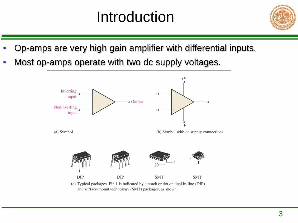
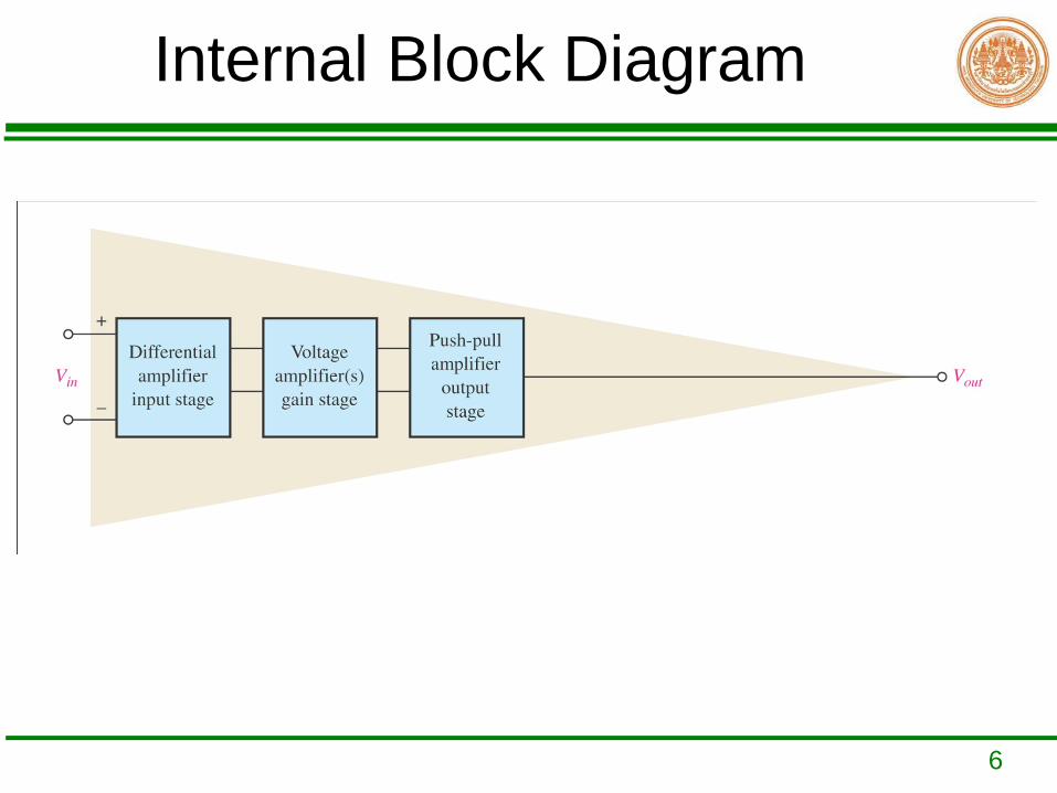
• Op-amps are very high gain amplifier with differential inputs. • Most op-amps operate with two dc supply voltages.
Introduction
4
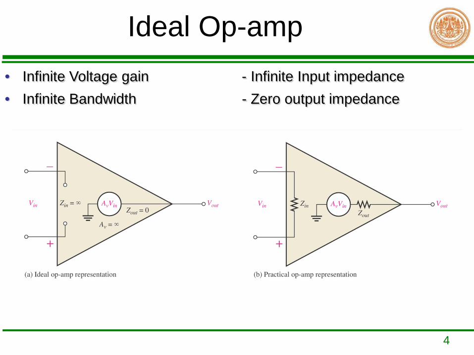
Ideal Op-amp• Infinite Voltage gain - Infinite Input impedance • Infinite Bandwidth - Zero output impedance
5
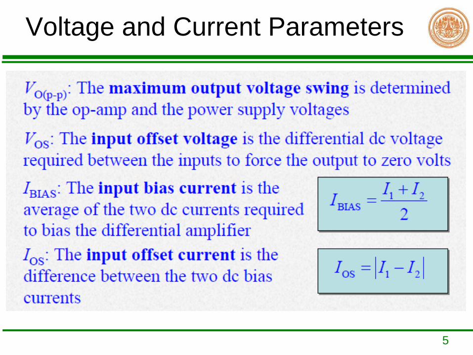
Voltage and Current Parameters
6
Internal Block Diagram
7
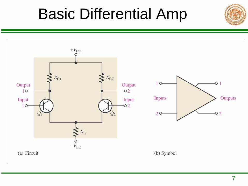
Basic Differential Amp
8
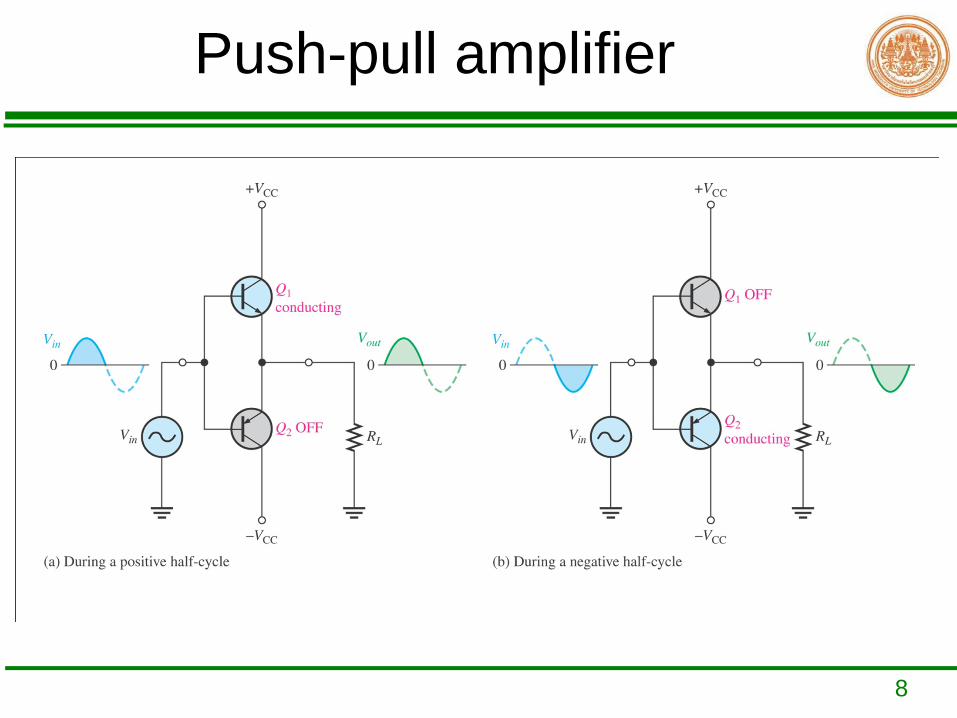
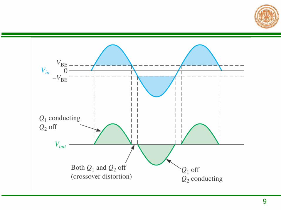
Push-pull amplifier
9
10
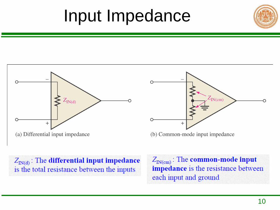
Input Impedance
11
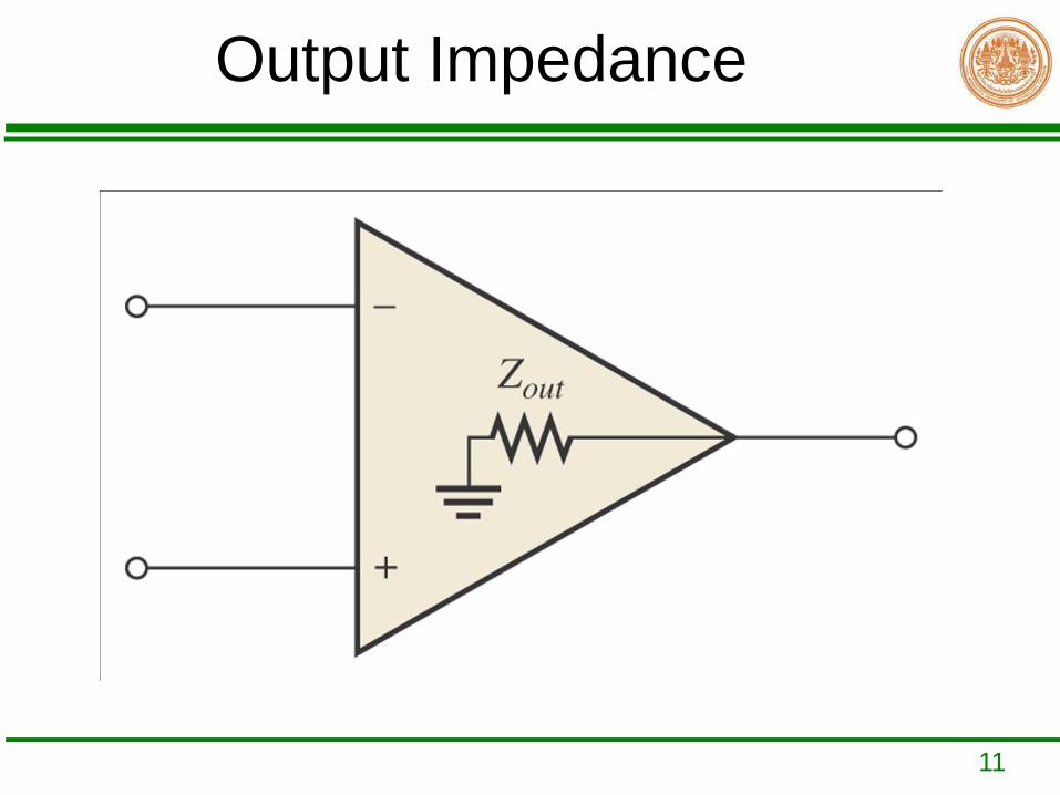
Output Impedance
12
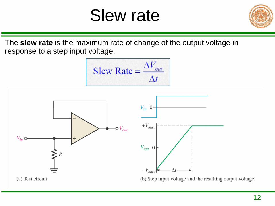
Slew rateThe slew rate is the maximum rate of change of the output voltage in response to a step input voltage.
13
Example
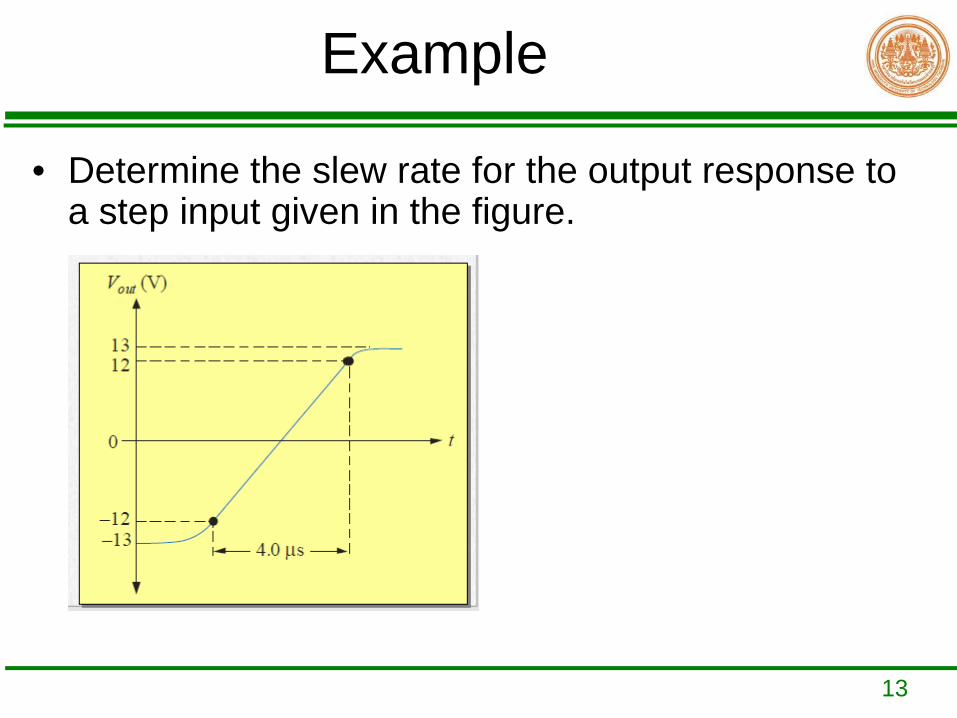
• Determine the slew rate for the output response to a step input given in the figure.
14
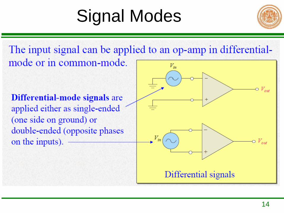
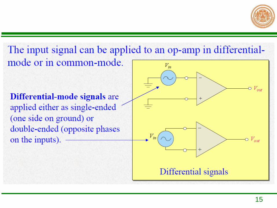
Signal Modes
15
16
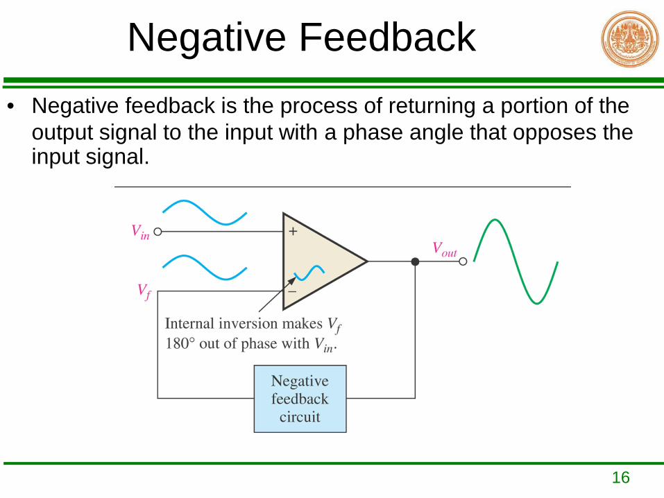
Negative Feedback• Negative feedback is the process of returning a portion of the
output signal to the input with a phase angle that opposes the input signal.
17
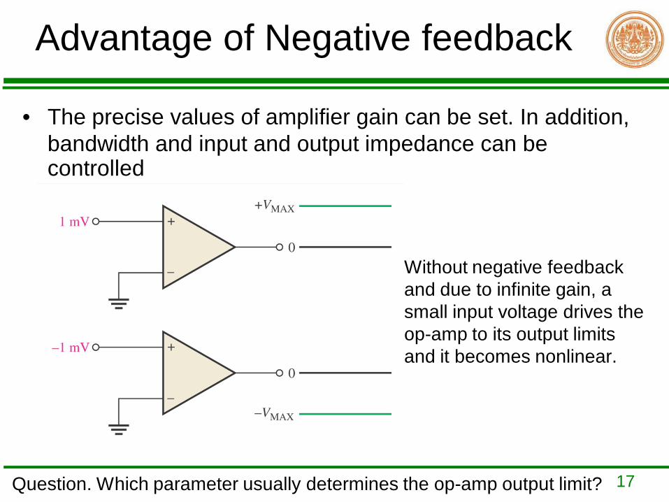
Advantage of Negative feedback
• The precise values of amplifier gain can be set. In addition, bandwidth and input and output impedance can be controlled
Without negative feedback and due to infinite gain, a small input voltage drives the op-amp to its output limits and it becomes nonlinear.
Question. Which parameter usually determines the op-amp output limit?
18
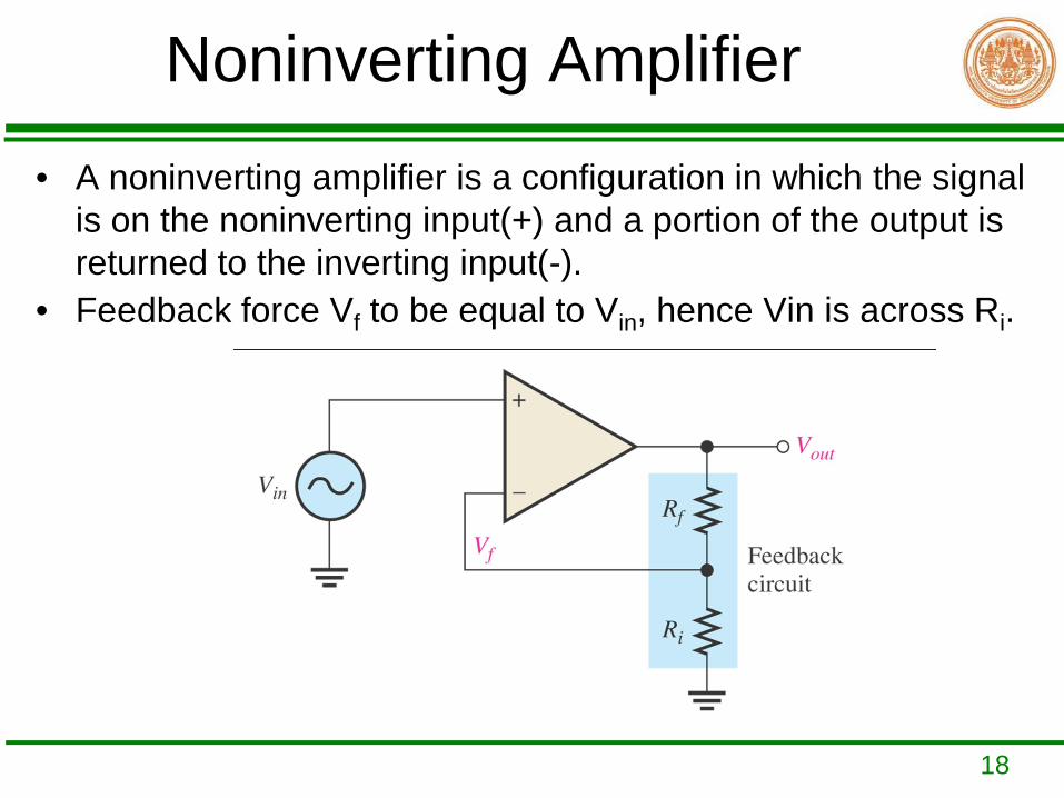
Noninverting Amplifier• A noninverting amplifier is a configuration in which the signal
is on the noninverting input(+) and a portion of the output is returned to the inverting input(-).
• Feedback force Vf to be equal to Vin, hence Vin is across Ri.
19
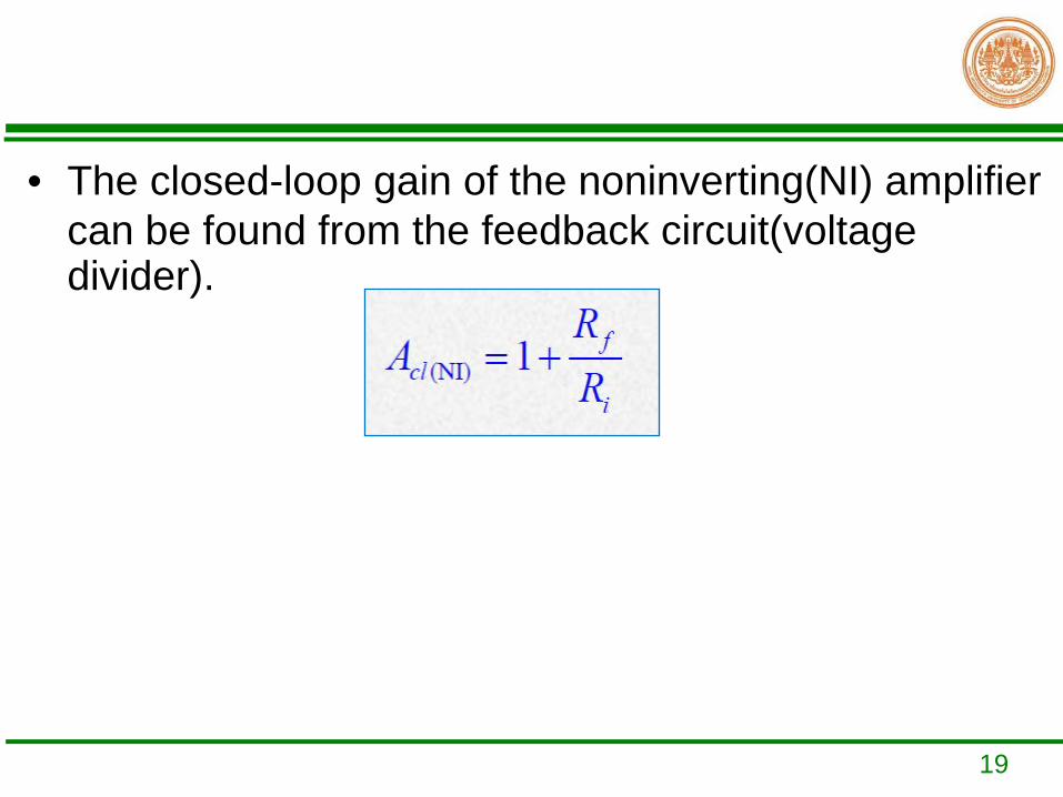
• The closed-loop gain of the noninverting(NI) amplifier can be found from the feedback circuit(voltage divider).
20
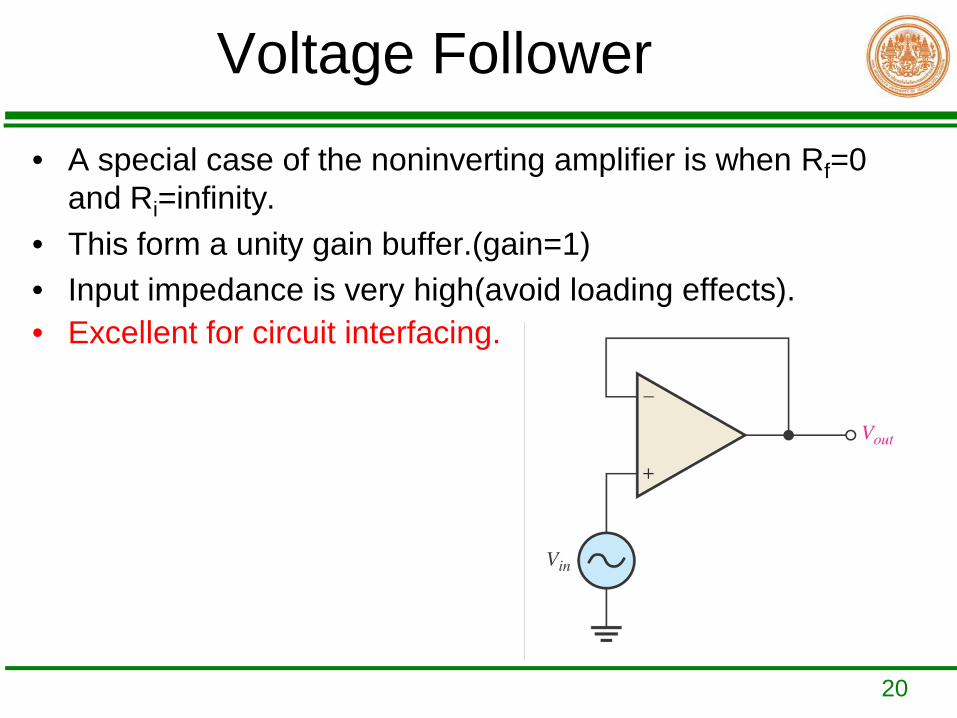
Voltage Follower• A special case of the noninverting amplifier is when Rf=0
and Ri=infinity. • This form a unity gain buffer.(gain=1)• Input impedance is very high(avoid loading effects).• Excellent for circuit interfacing.
21
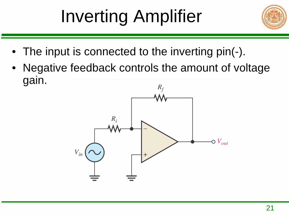
Inverting Amplifier
• The input is connected to the inverting pin(-). • Negative feedback controls the amount of voltage
gain.
22
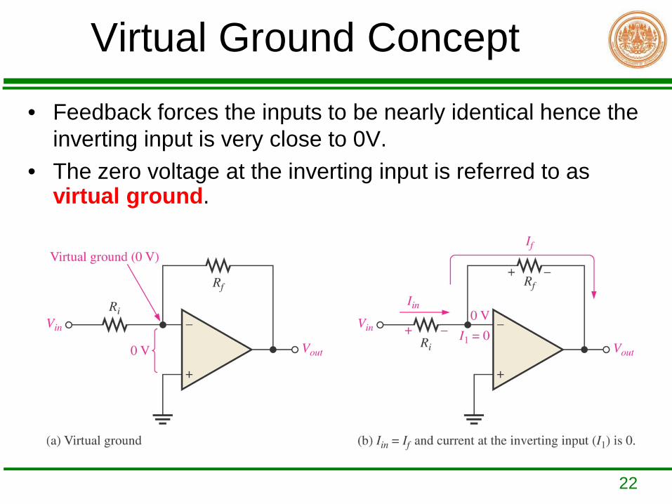
Virtual Ground Concept• Feedback forces the inputs to be nearly identical hence the
inverting input is very close to 0V.• The zero voltage at the inverting input is referred to as
virtual ground.
23
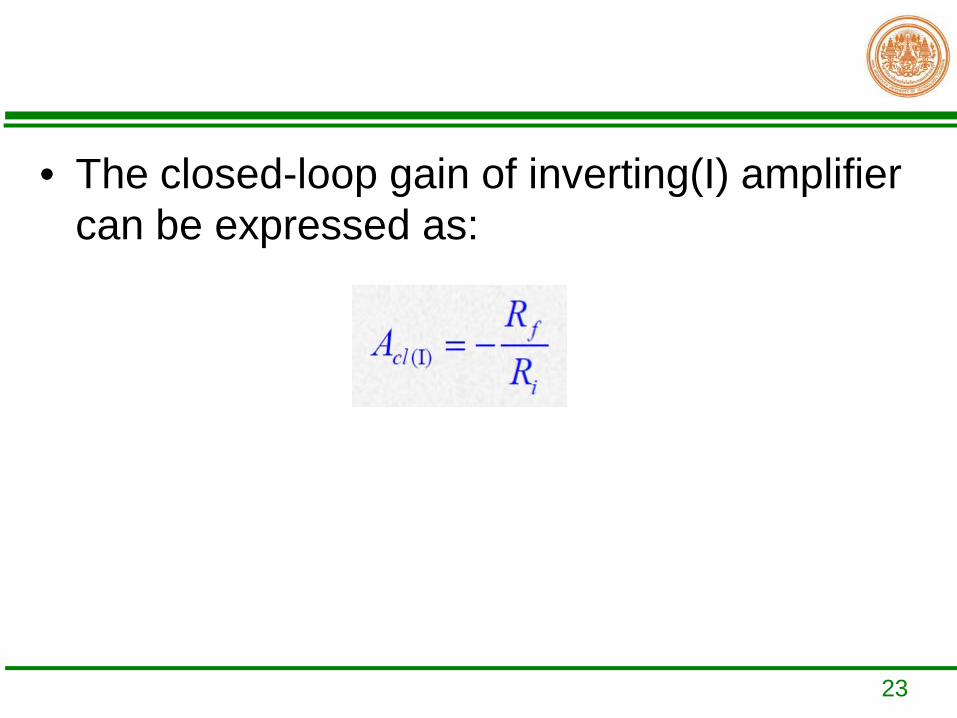
• The closed-loop gain of inverting(I) amplifier can be expressed as:
24
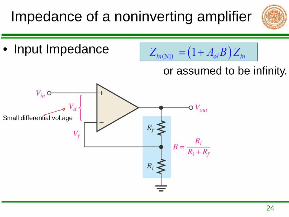
Impedance of a noninverting amplifier
• Input Impedance or assumed to be infinity.
Small differential voltage
25
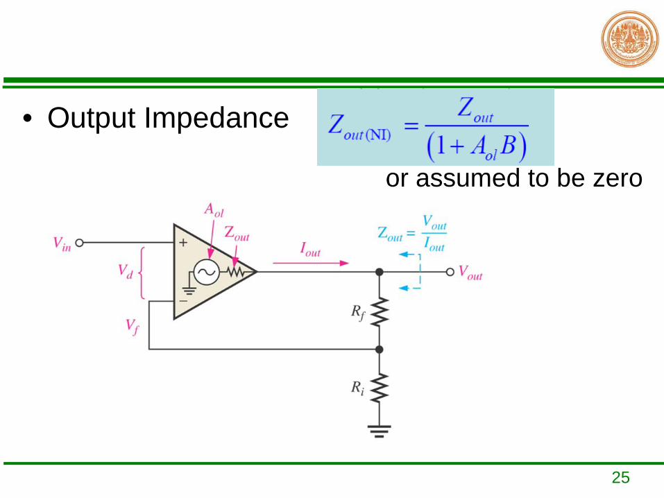
• Output Impedance
or assumed to be zero
26
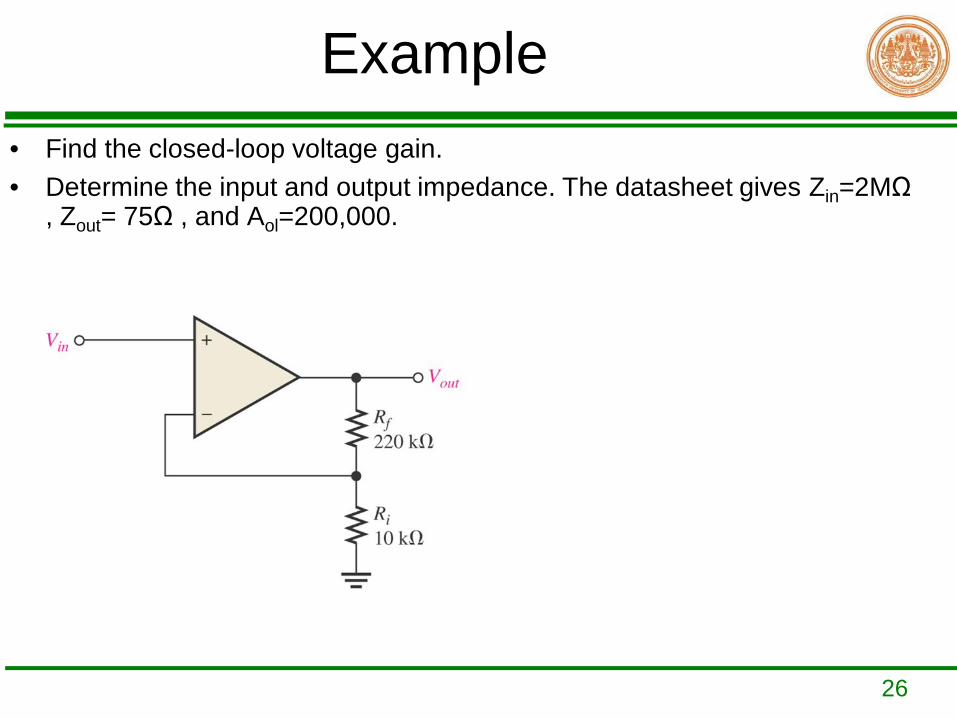
Example• Find the closed-loop voltage gain.• Determine the input and output impedance. The datasheet gives Zin=2MΩ
, Zout= 75Ω , and Aol=200,000.
27
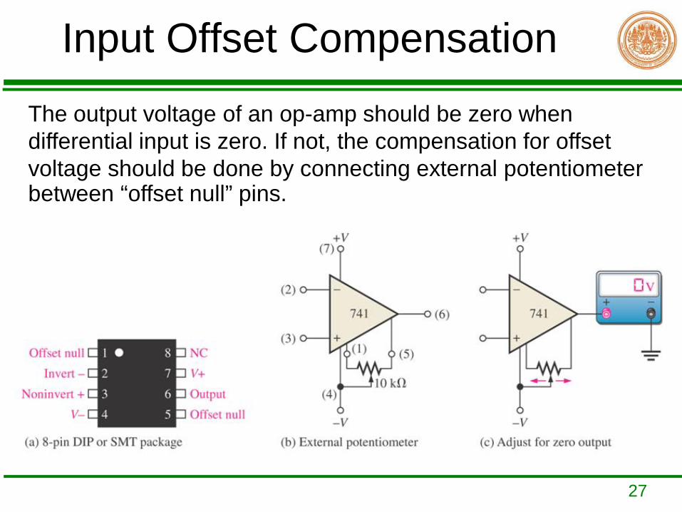
Input Offset Compensation The output voltage of an op-amp should be zero when differential input is zero. If not, the compensation for offset voltage should be done by connecting external potentiometer between “offset null” pins.
28
Open-loop response
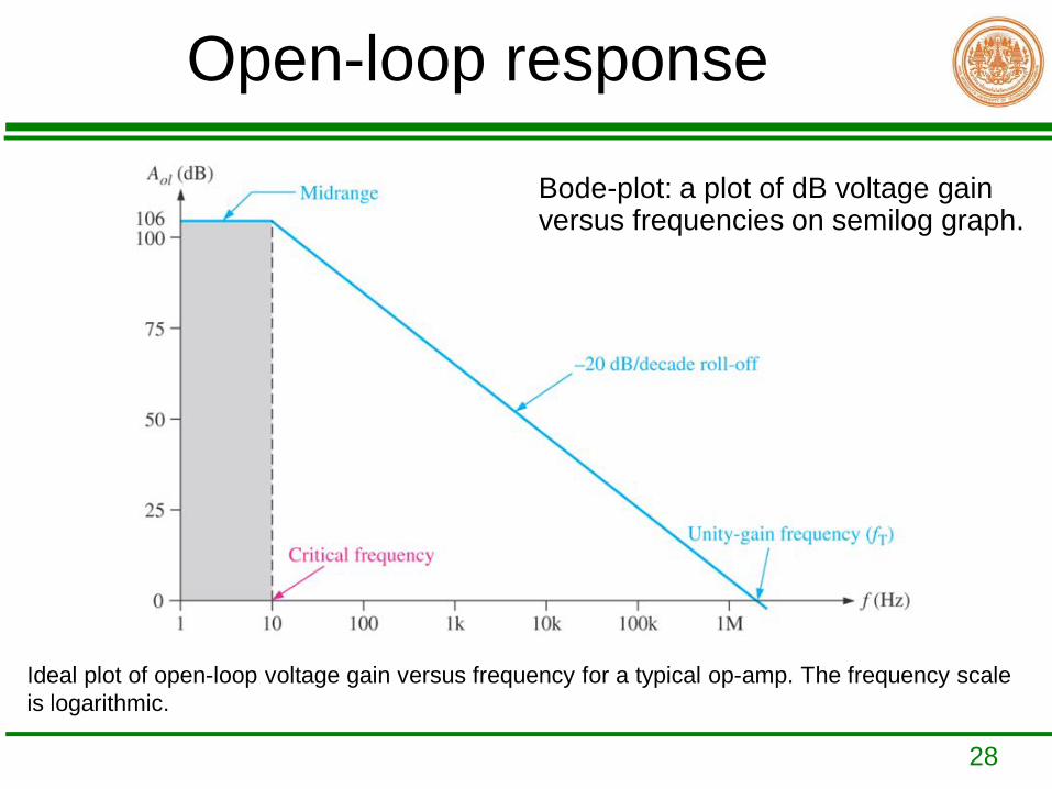
Ideal plot of open-loop voltage gain versus frequency for a typical op-amp. The frequency scale is logarithmic.
Bode-plot: a plot of dB voltage gain versus frequencies on semilog graph.
29
Closed-loop Frequency Response
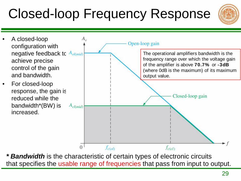
• A closed-loop configuration with negative feedback to achieve precise control of the gain and bandwidth.
• For closed-loop response, the gain is reduced while the bandwidth*(BW) is increased.
* Bandwidth is the characteristic of certain types of electronic circuits that specifies the usable range of frequencies that pass from input to output.
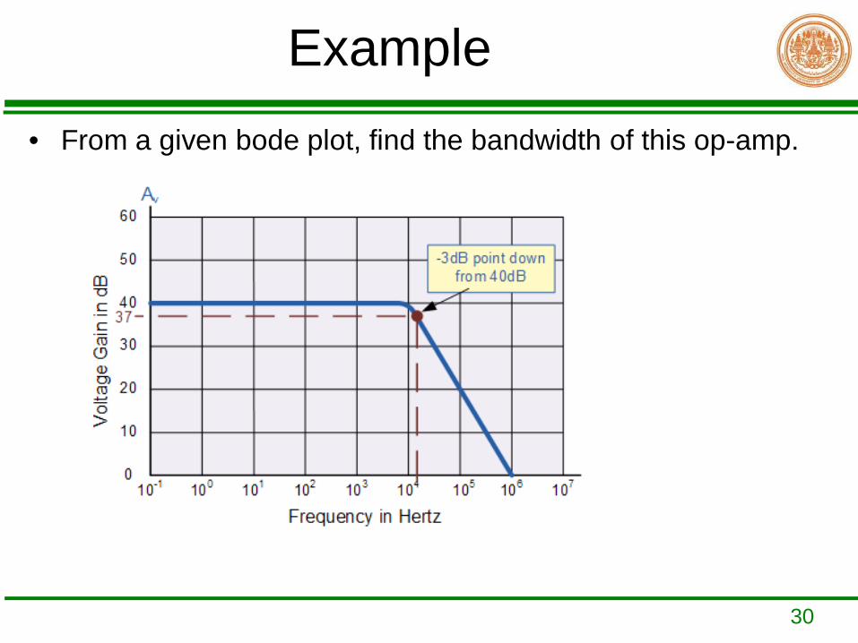
The operational amplifiers bandwidth is the frequency range over which the voltage gain of the amplifier is above 70.7% or -3dB(where 0dB is the maximum) of its maximum output value.
30
Example• From a given bode plot, find the bandwidth of this op-amp.
31
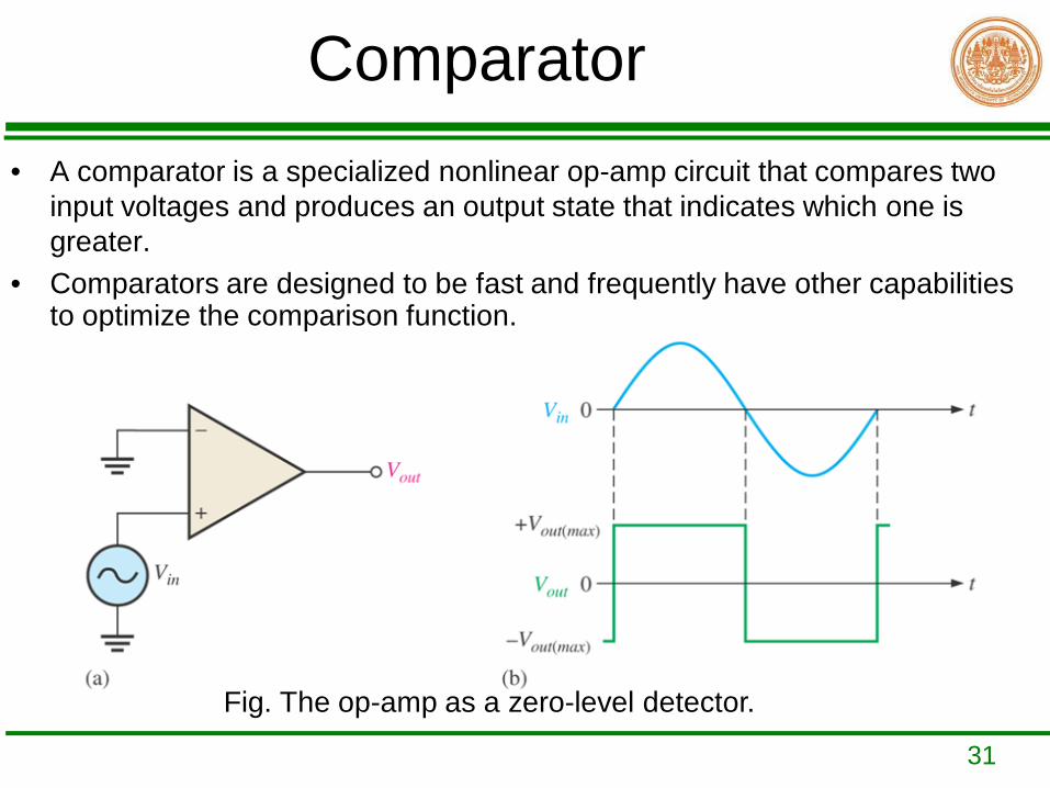
Comparator• A comparator is a specialized nonlinear op-amp circuit that compares two
input voltages and produces an output state that indicates which one is greater.
• Comparators are designed to be fast and frequently have other capabilities to optimize the comparison function.
Fig. The op-amp as a zero-level detector.
32
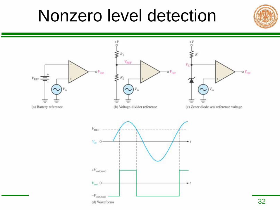
Nonzero level detection
33
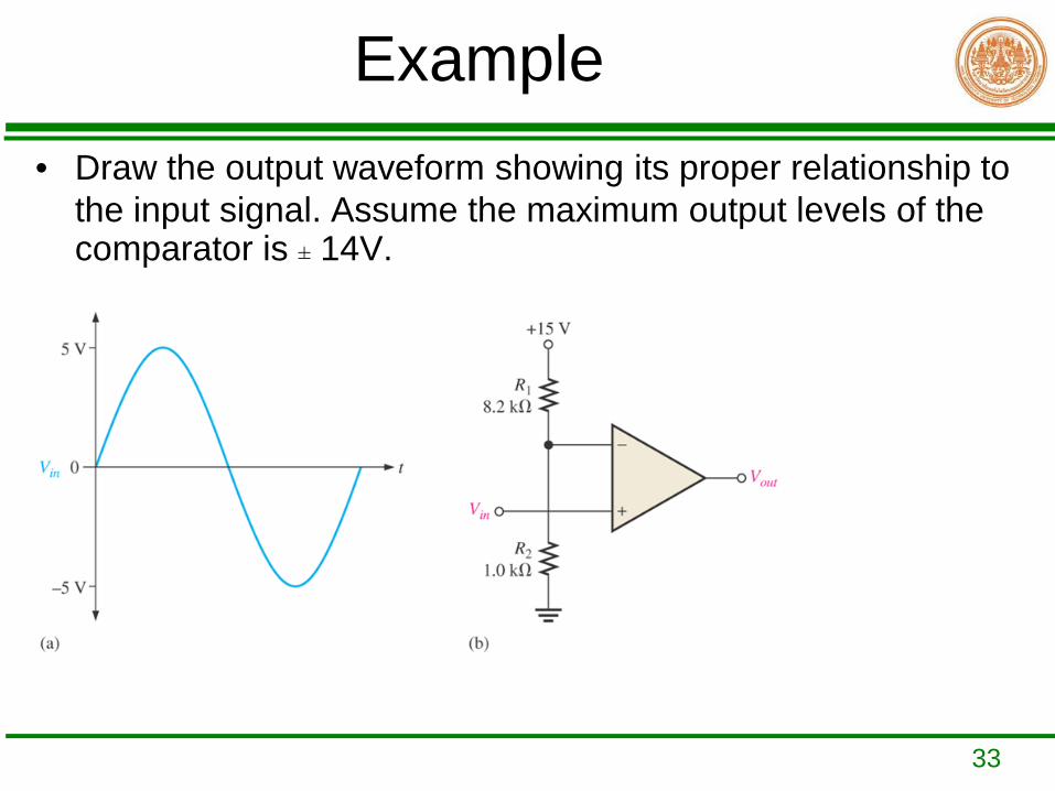
Example• Draw the output waveform showing its proper relationship to
the input signal. Assume the maximum output levels of the comparator is ± 14V.
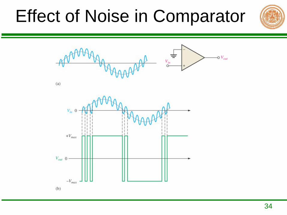
34
Effect of Noise in Comparator
35
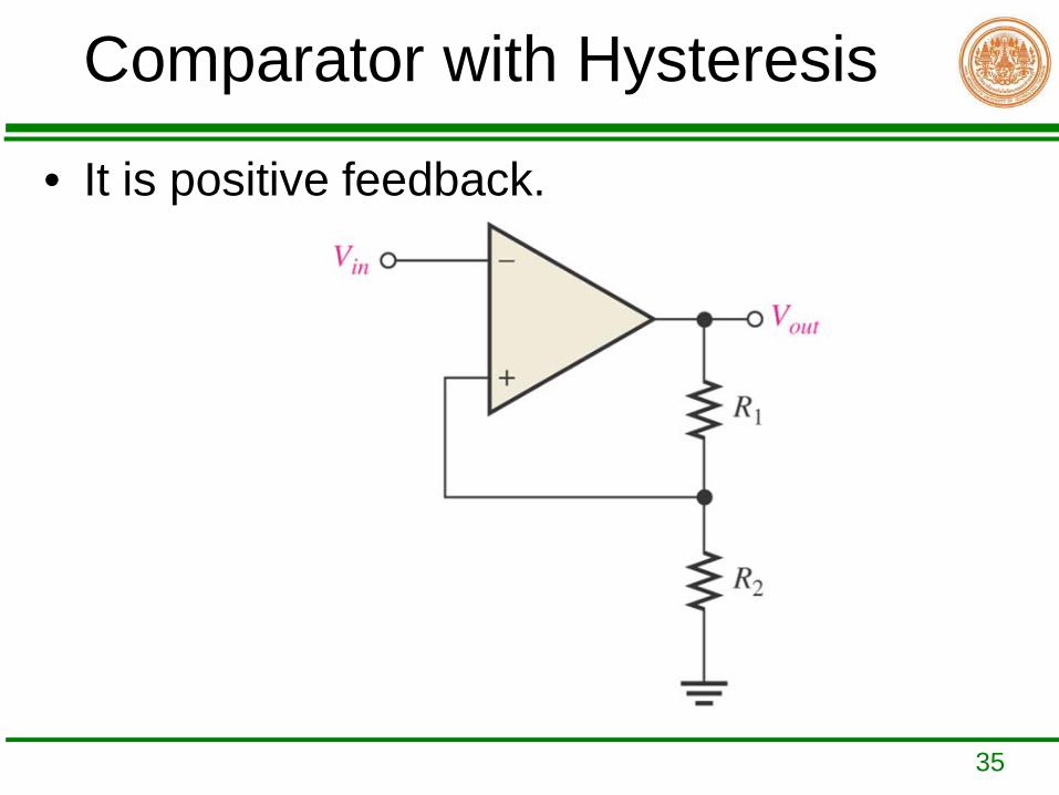
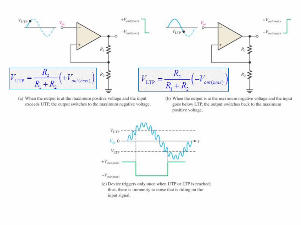
Comparator with Hysteresis
• It is positive feedback.
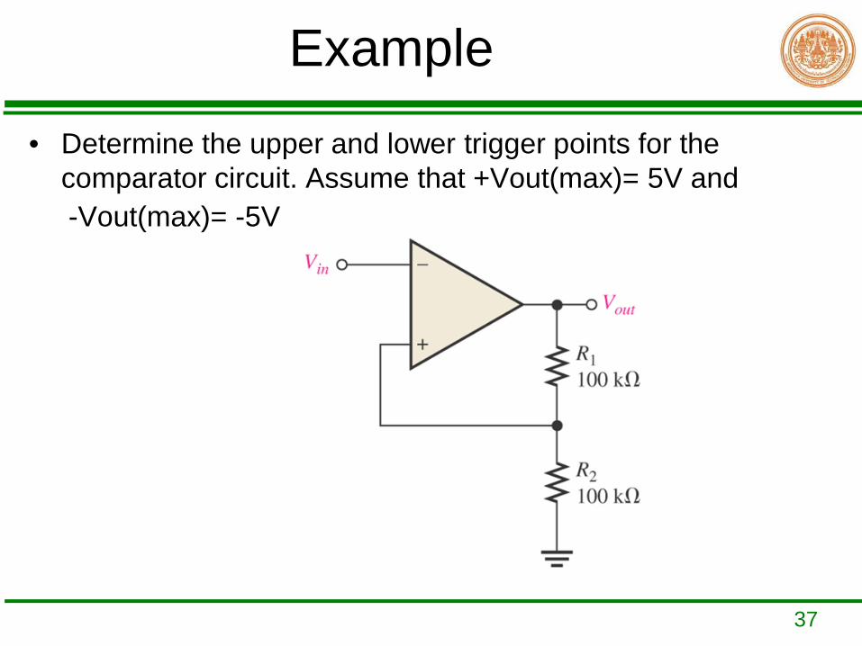
37
Example• Determine the upper and lower trigger points for the
comparator circuit. Assume that +Vout(max)= 5V and -Vout(max)= -5V
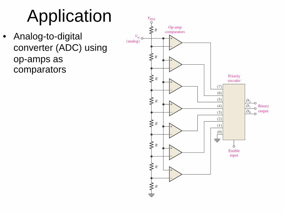
Application• Analog-to-digital
converter (ADC) using op-amps as comparators
39
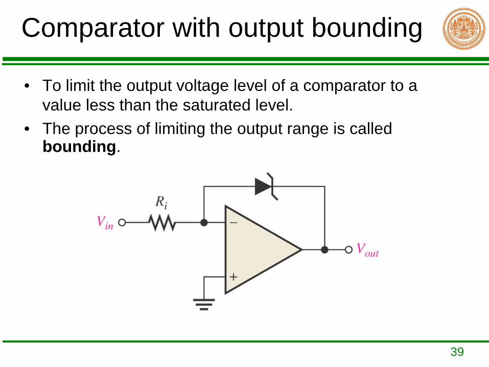
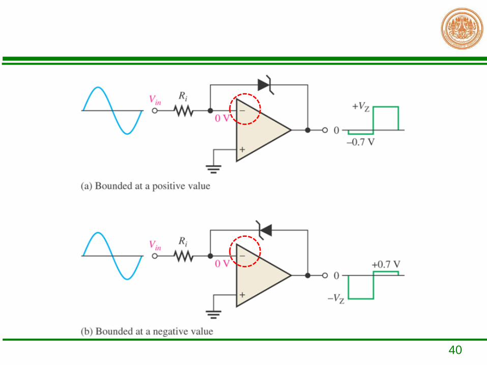
Comparator with output bounding
• To limit the output voltage level of a comparator to a value less than the saturated level.
• The process of limiting the output range is called bounding.
40
41
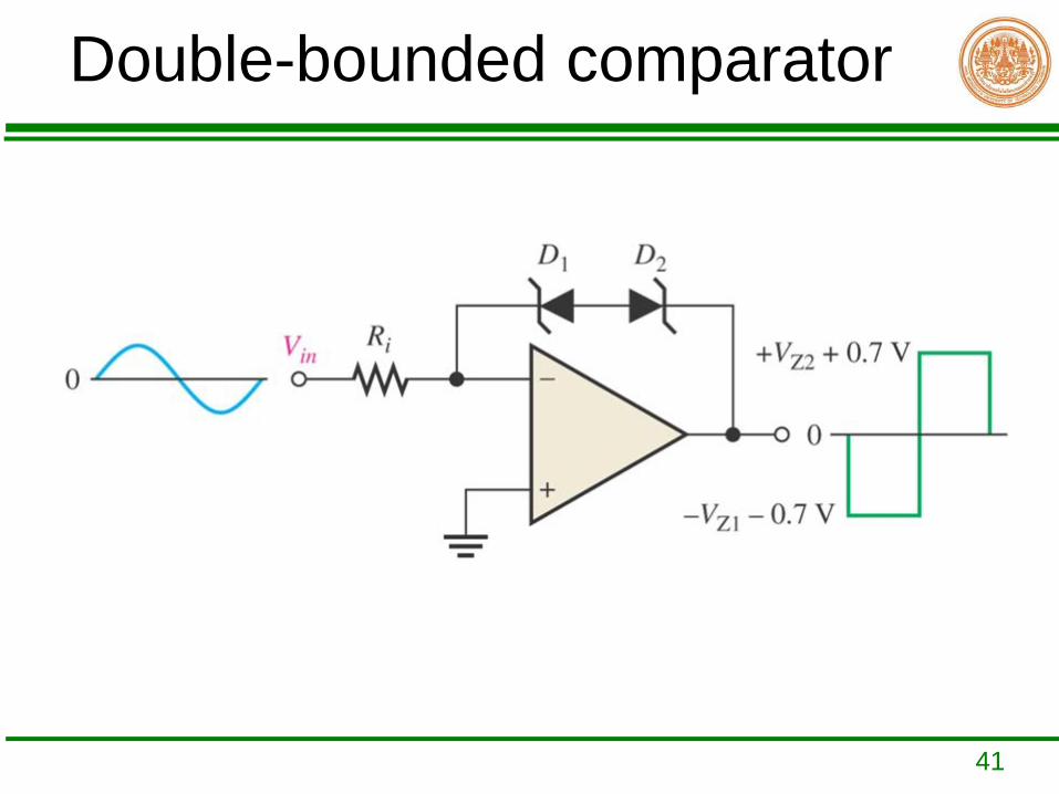
Double-bounded comparator
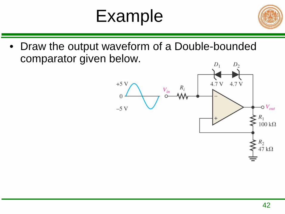
42
Example• Draw the output waveform of a Double-bounded
comparator given below.
43
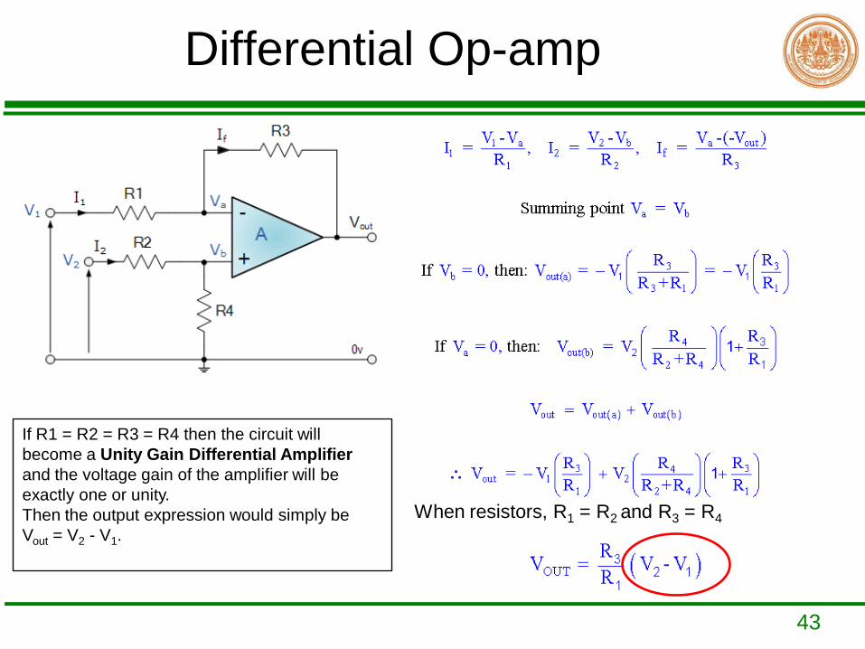
Differential Op-amp
When resistors, R1 = R2 and R3 = R4
If R1 = R2 = R3 = R4 then the circuit will become a Unity Gain Differential Amplifierand the voltage gain of the amplifier will be exactly one or unity. Then the output expression would simply be Vout = V2 - V1.
44
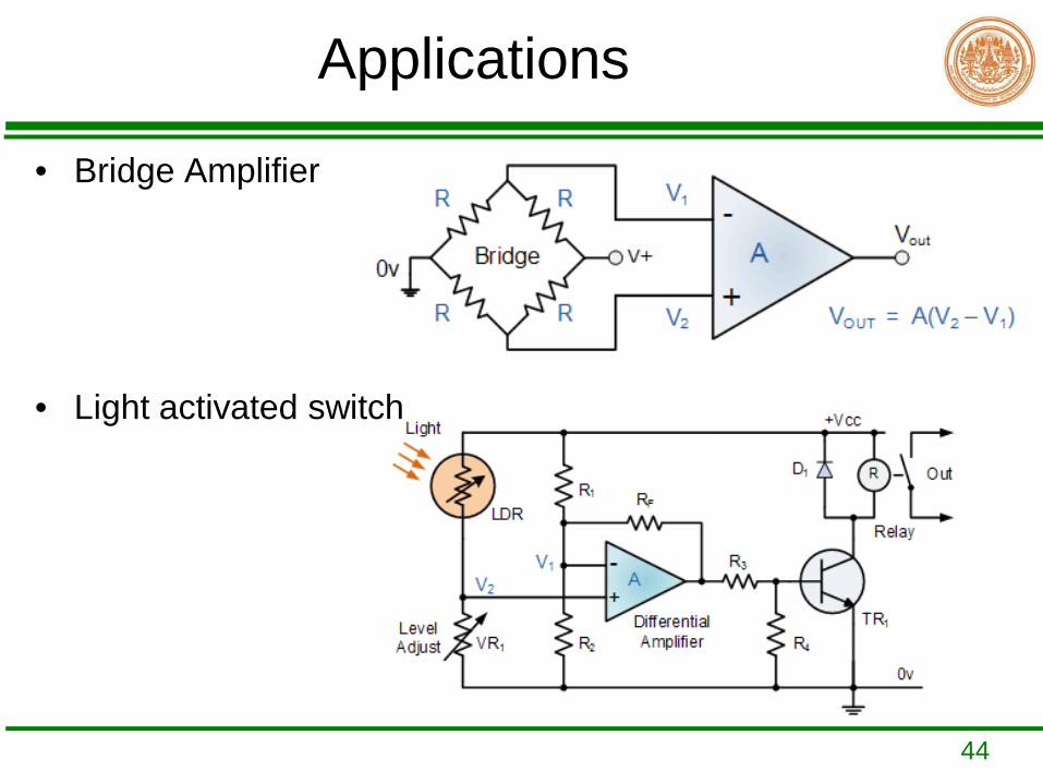
Applications
• Bridge Amplifier
• Light activated switch
45
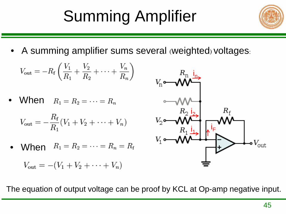
Summing Amplifier
• A summing amplifier sums several (weighted) voltages:
• When
• When
The equation of output voltage can be proof by KCL at Op-amp negative input.
iFi1
i2
in
46
Applictions
• Offset adjustment• Voltage level shifter• Zero-span circuit• Digital to analog converter(DAC or D/A)
47
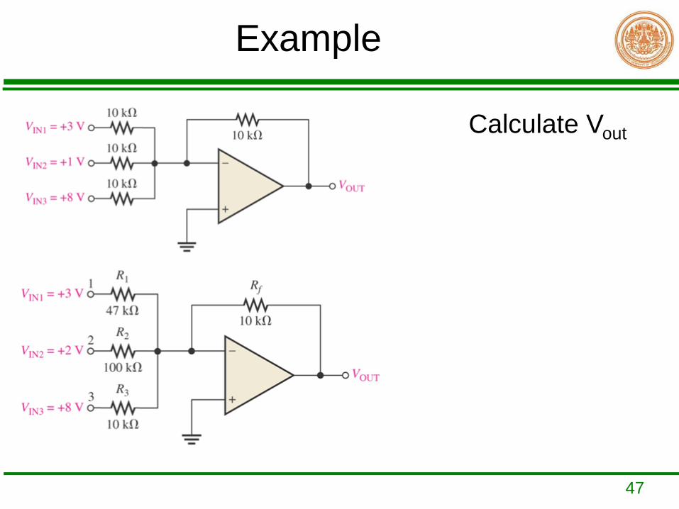
Example
Calculate Vout
48
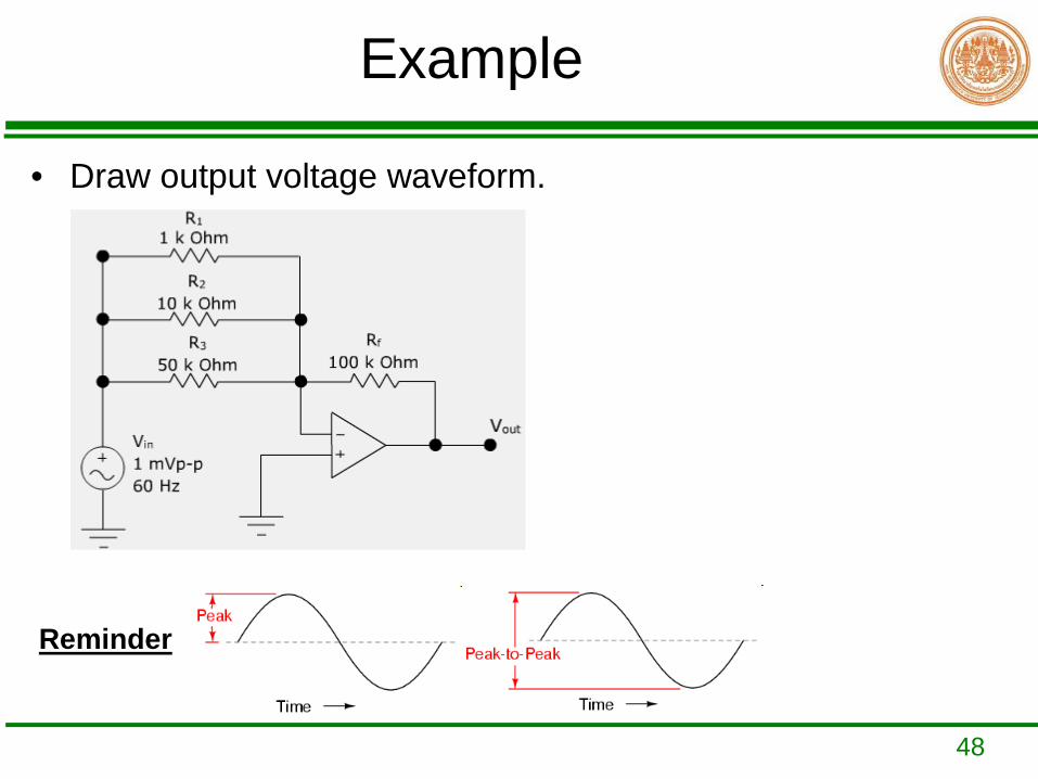
Example
• Draw output voltage waveform.
Reminder
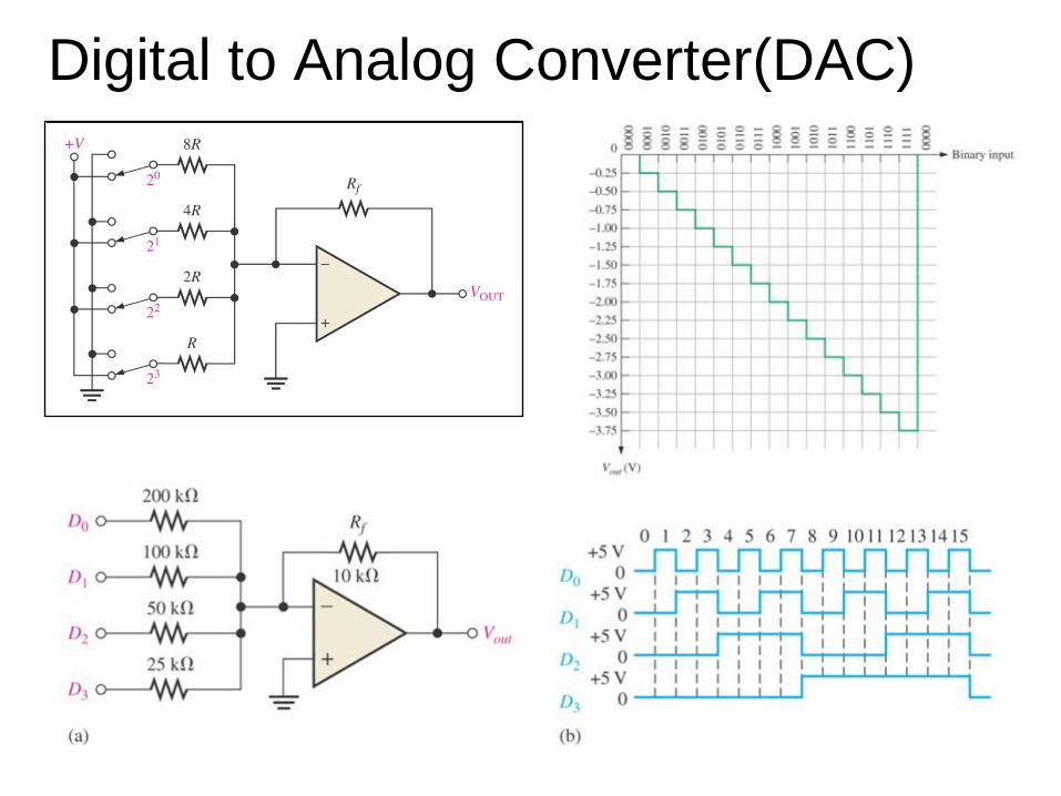
Digital to Analog Converter(DAC)
50
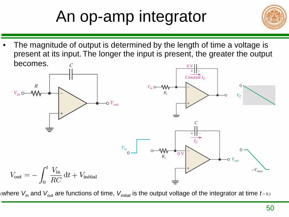
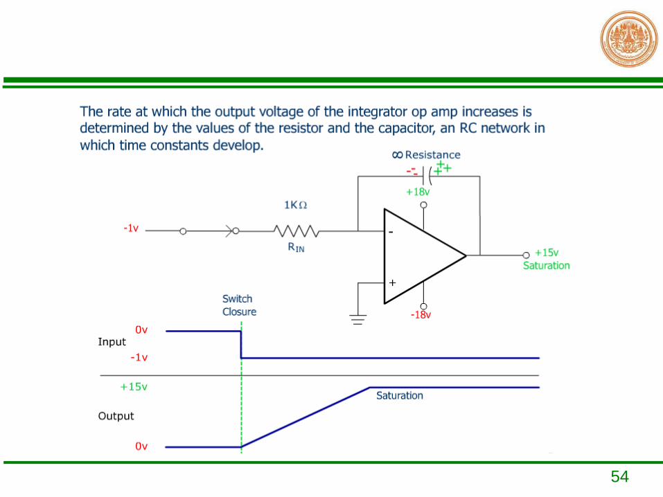
An op-amp integrator• The magnitude of output is determined by the length of time a voltage is
present at its input. The longer the input is present, the greater the output becomes.
(where Vin and Vout are functions of time, Vinitial is the output voltage of the integrator at time t = 0.)
51
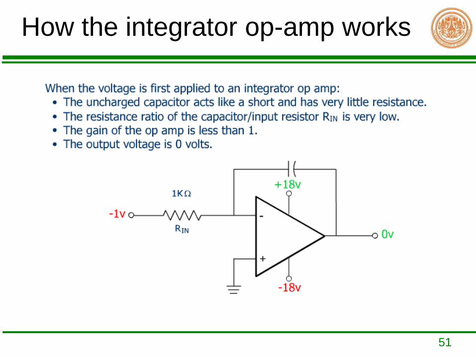
How the integrator op-amp works
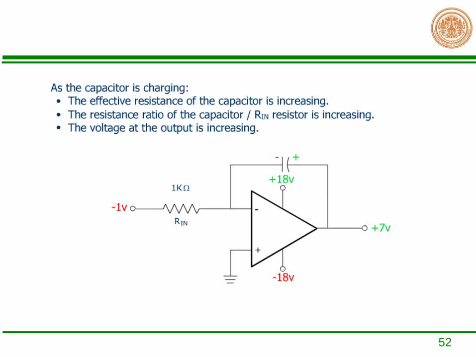
52
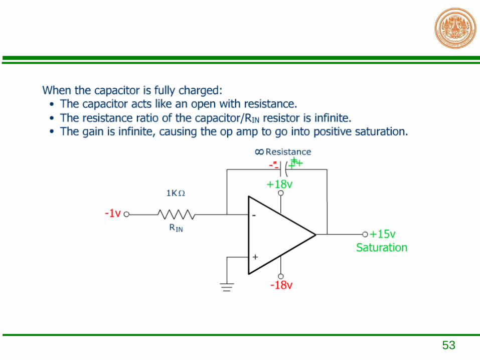
53
54
55
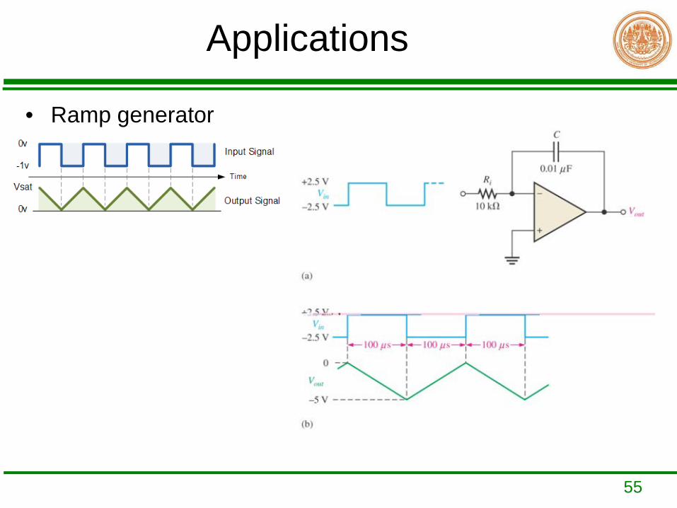
Applications
• Ramp generator
56
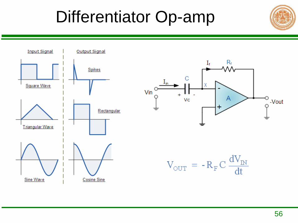
Differentiator Op-amp
57
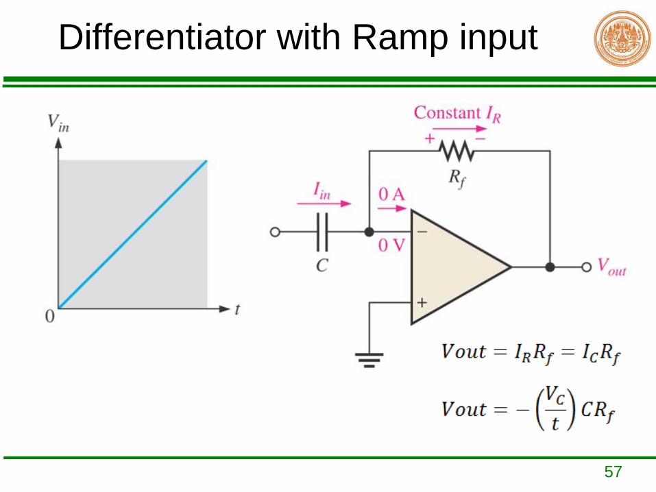
Differentiator with Ramp input
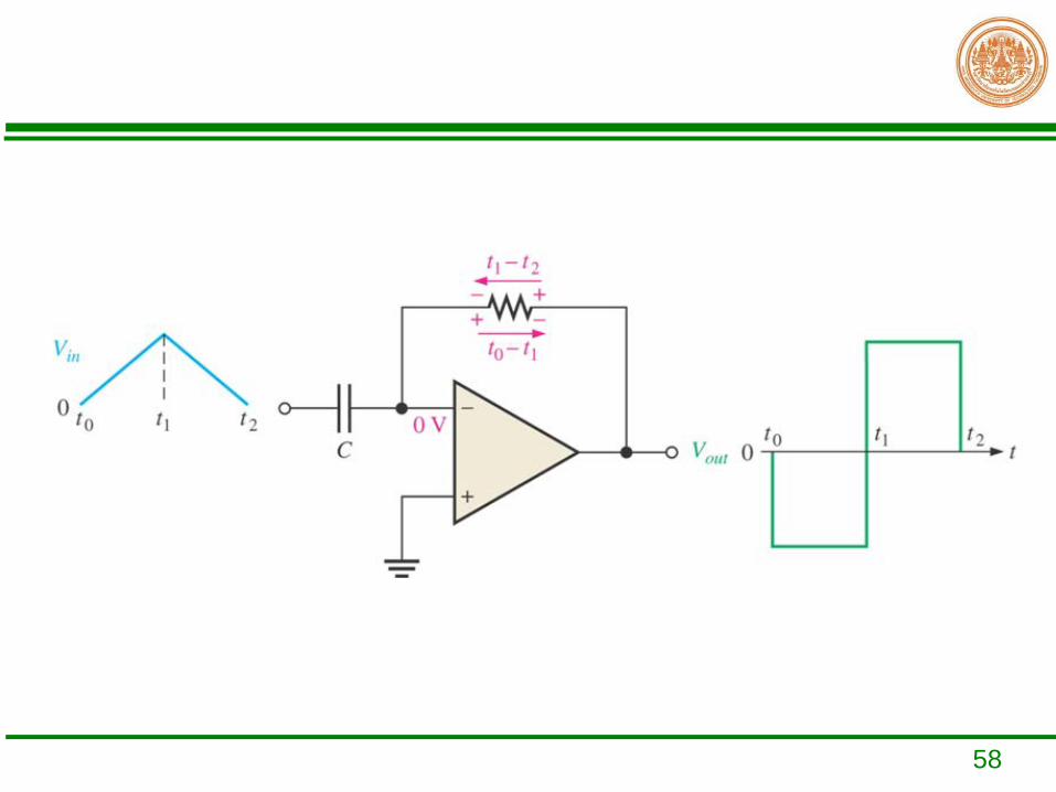
58

59
Example
Determine the output voltage of the ideal differentiator in figure below.