Embed Size (px)
Citation preview
Operation on Low-Sulphur FuelsMAN B&W Two-stroke Engines

Content
Introduction ..................................................................................................... 5
Latest Emission Control Regulations ................................................................. 6
The International Maritime Organisation (IMO) .............................................. 6
California Air Resources Board .................................................................... 6
The EU ....................................................................................................... 6
Incompatibility of Fuels ..................................................................................... 7
Operational Considerations Related to Operating
MAN B&W Two-stroke Engines on Low-sulphur Fuels ....................................... 8
Correlation between fuel sulphur level and cylinder condition ...................... 8
Distillates ....................................................................................................... 10
Influence of fuel lubricity and viscosity at engine inlet ................................. 11
Other considerations when operating on distillates .................................... 13
Change-over between heavy fuel and distillates ......................................... 14
Ignition and Combustion Characteristics of Low-Sulphur Fuels ........................ 15
Case story ................................................................................................ 16
Fuel Oil Auxiliary Systems ............................................................................... 18
Fuel oil system, No. 1 (Fig. 15) .................................................................. 18
Fuel oil system, No. 2 (Fig. 16) .................................................................. 18
Fuel oil system, No. 3 (Fig. 17) .................................................................. 18
Cylinder oil system, No. 1 (Fig. 18) ............................................................ 19
Cylinder oil system, No. 2 (Fig. 19) ............................................................ 19
Cylinder oil system, No. 3 (Fig. 20) ............................................................ 19
Experience with Wet Scrubbing Techniques and Expectations to Future Use .. 20
Summary ....................................................................................................... 21
Abbreviations ................................................................................................. 21
References..................................................................................................... 21

5
Operation on Low-Sulphur Fuels
Introduction
The average sulphur content of heavy
fuel oil (HFO) used for marine diesel en-
gines is 2.7% today. This will undoubt-
edly change with the coming emission
legislation, which will lower the emis-
sion limits of SOx, NOx, particulate, HC,
CO and CO2. See also list of abbrevia-
tions.
So far, the authorities have reduced the
SOx content in the exhaust gas by in-
troducing limits on the content of sul-
phur in the heavy fuel (HFO) used. This
is a much more efficient and straight-
forward solution, obtained from the re-
fining process, than the installation of
separate SOx cleaning techniques on
board each vessel.
However, this solution still requires
that it is feasible for the refineries to
lower the sulphur level at a reason-
able cost and effort. So far, the ques-
tion is whether there will be sufficient
low-sulphur HFO available in the future,
and whether marine diesel and gas
oils will be used to any wider extent.
This is a somewhat political question,
which will not be discussed in this pa-
per, but which could result in less HFO
produced, more distillate used, and a
higher avarage sulphur content in the
remaining heavy fuel.
However, we will highlight for the Ma-
rine Industry, the technical areas which
MAN Diesel & Turbo expects will be af-
fected when changing from higher sul-
phur fuel oils to lower sulphur fuel oils.
We will inform of the latest experience
gained from operation on low-sulphur
fuel, and also of the potential opera-
tional difficulties if the main engine and
auxilliary systems are not prepared.
In cooperation with a number of scrub-
ber suppliers, MAN Diesel & Turbo has
completed more than 170 tests on a 1
MW research plant in Denmark. Futher-
more, the experience from a full scale
test in progress on a 20 MW main en-
gine scrubber will be described in a
separate chapter.
Most MAN B&W two-stroke engines of
today are operating on fuels with sul-
phur levels higher than 1.5%. This gives
us much experience with high-sulphur
fuels. However, on the basis of opera-
tion on power stations and special ma-
rine vessels designated for operation
on low-sulphur fuel, we have created
the guidelines described in this paper.
It should also be mentioned that on
testbed all two-stroke engines are op-
erated on standard environmentally
friendly fuel oil, which is typically a land-
based diesel oil with a very low sulphur
content and viscosity but, also in this
condition, the two-stroke engine oper-
ates successfully as long as the neces-
sary precautions are being taken.
Operation on Low-Sulphur Fuels
Latest Emission Control RegulationsThe International Maritime
Organisation (IMO)
The IMO Annex VI of MARPOL 73/78,
Regulations for the Prevention of Air
Pollution from Ships has been in force
since May 2005.
Thus, the sulphur oxides (SOx) limit ap-
plies to all vessels in the category of
ships with an engine power output of
more than 130 kW.
The general international limit on sul-
phur is reduced from 5% to 4.5%
through the ISO 8217 fuel standard.
IMO has specified that, in future, further
limitations will be imposed on SOx as
well as on other components in the ex-
haust gas.
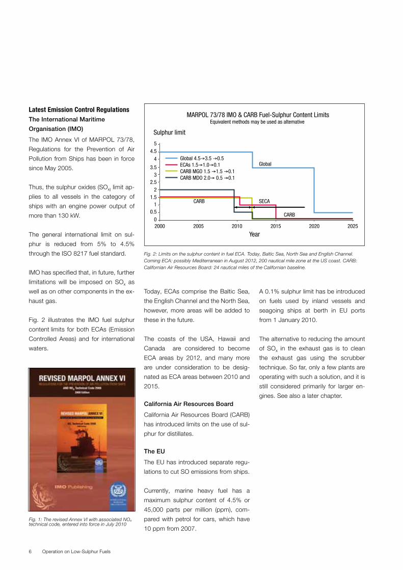
Fig. 2 illustrates the IMO fuel sulphur
content limits for both ECAs (Emission
Controlled Areas) and for international
waters.
Today, ECAs comprise the Baltic Sea,
the English Channel and the North Sea,
however, more areas will be added to
these in the future.
The coasts of the USA, Hawaii and
Canada are considered to become
ECA areas by 2012, and many more
are under consideration to be desig-
nated as ECA areas between 2010 and
2015.
California Air Resources Board
California Air Resources Board (CARB)
has introduced limits on the use of sul-
phur for distillates.
The EU
The EU has introduced separate regu-
lations to cut SO emissions from ships.
Currently, marine heavy fuel has a
maximum sulphur content of 4.5% or
45,000 parts per million (ppm), com-
pared with petrol for cars, which have
10 ppm from 2007.
A 0.1% sulphur limit has be introduced
on fuels used by inland vessels and
seagoing ships at berth in EU ports
from 1 January 2010.
The alternative to reducing the amount
of SOx in the exhaust gas is to clean
the exhaust gas using the scrubber
technique. So far, only a few plants are
operating with such a solution, and it is
still considered primarily for larger en-
gines. See also a later chapter.
Operation on Low-Sulphur Fuels6
Fig. 2: Limits on the sulphur content in fuel ECA. Today, Baltic Sea, North Sea and English Channel. Coming ECA: possibly Mediterranean in August 2012, 200 nautical mile zone at the US coast. CARB: Californian Air Resources Board: 24 nautical miles of the Californian baseline.
Fig. 1: The revised Annex VI with associated NOx technical code, entered into force in July 2010
MARPOL 73/78 IMO & CARB Fuel-Sulphur Content LimitsEquivalent methods may be used as altemative
Global 4.5→3.5 →0.5ECAs 1.5→1.0→0.1CARB MGO 1.5 →1.5 →0.1CARB MDO 2.0→ 0.5 →0.1
Sulphur limit
Year
Global
SECACARB
CARB
54.5
4
3.53
2.52
1.51
0.5
2000 2005 2010 2015 2020 20250
7
Incompatibility of Fuels
Due to the current considerable price
difference, we do not expect total
change-overs from heavy fuel to distil-
lates, see Table I. However, an operator
could be forced to change over for rea-
sons of fuel availability.
Low-sulphur heavy fuel has a some-
what higher price than the high sulphur
heavy fuel, due to increasing demand
and the cost of the desulphurisation
process.
When switching from heavy fuel to a
distillate fuel with a low aromatic hy-
drocarbon content, there is a risk of
incompatibility between the two prod-
ucts. The change-over procedure takes
quite some time, during which there will
be a mix of the two very different fuels
for an extended period of time. The as-
phaltenes of the heavy fuel is likely to
precipitate as heavy sludge, with filter
clogging as a possible result.
Even though incompatibility seldom oc-
curs, the most obvious way to avoid
this is to check the compatibility be-
tween the fuels before bunkering. This
can be done manually with a kit on
board, or via an independent labora-
tory. The latter often being too slow a
process, as the ship will already have
left the harbour before the laboratory
returns with the test result. Therefore, in
practice, and in the event that the fuel
supplier is not supplying both low and
high sulphur fuels, the incompatibilities
will not be discovered until both fuels
are on board.
BP Marine has found that even though
the TSP (Total Sediment Potential) and
TSE (Total Sediment Existing) values of
the fuel are completely satisfactory, still
or small number of fuel deliveries give
rise to complaints of filter blocking, ex-
cessive sludge, etc. It is suspected that
most at these incidents are due to fuel
incompatibility.
When blending for low-sulphur fuel more
cases of incompatibility might be seen
Operation on Low-Sulphur Fuels
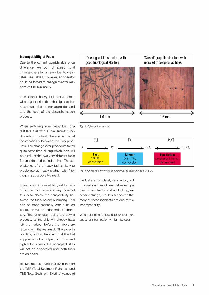
‘Open’ graphite structure withgood tribological abilities
‘Closed’ graphite structure withreduced tribological abilities
1.6 mm 1.6 mm
Fig. 3: Cylinder liner surface
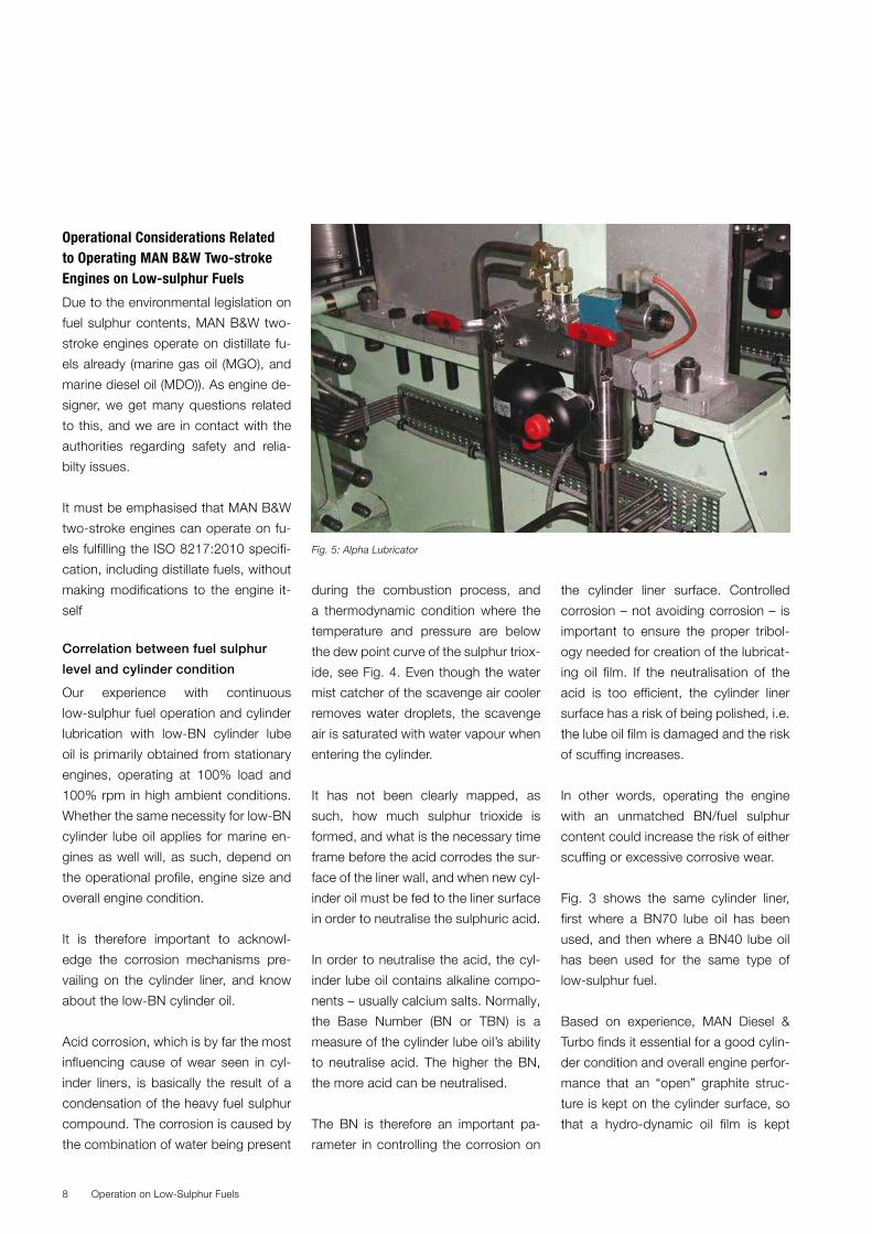
Fast100%
conversion
Slower0.3 - 7%
conversion
Equilibriumpressure & temp.
dependent
S SO2 SO3 H2SO4
[02] [0] [H20]
Fig. 4: Chemical conversion of sulphur (S) to sulphuric acid (H2SO4)
Operational Considerations Related to Operating MAN B&W Two-stroke Engines on Low-sulphur Fuels
Due to the environmental legislation on
fuel sulphur contents, MAN B&W two-
stroke engines operate on distillate fu-
els already (marine gas oil (MGO), and
marine diesel oil (MDO)). As engine de-
signer, we get many questions related
to this, and we are in contact with the
authorities regarding safety and relia-
bilty issues.
It must be emphasised that MAN B&W
two-stroke engines can operate on fu-
els fulfilling the ISO 8217:2010 specifi-
cation, including distillate fuels, without
making modifications to the engine it-
self
Correlation between fuel sulphur
level and cylinder condition
Our experience with continuous
low-sulphur fuel operation and cylinder
lubrication with low-BN cylinder lube
oil is primarily obtained from stationary
engines, operating at 100% load and
100% rpm in high ambient conditions.
Whether the same necessity for low-BN
cylinder lube oil applies for marine en-
gines as well will, as such, depend on
the operational profile, engine size and
overall engine condition.
It is therefore important to acknowl-
edge the corrosion mechanisms pre-
vailing on the cylinder liner, and know
about the low-BN cylinder oil.
Acid corrosion, which is by far the most
influencing cause of wear seen in cyl-
inder liners, is basically the result of a
condensation of the heavy fuel sulphur
compound. The corrosion is caused by
the combination of water being present
during the combustion process, and
a thermodynamic condition where the
temperature and pressure are below
the dew point curve of the sulphur triox-
ide, see Fig. 4. Even though the water
mist catcher of the scavenge air cooler
removes water droplets, the scavenge
air is saturated with water vapour when
entering the cylinder.
It has not been clearly mapped, as
such, how much sulphur trioxide is
formed, and what is the necessary time
frame before the acid corrodes the sur-
face of the liner wall, and when new cyl-
inder oil must be fed to the liner surface
in order to neutralise the sulphuric acid.
In order to neutralise the acid, the cyl-
inder lube oil contains alkaline compo-
nents – usually calcium salts. Normally,
the Base Number (BN or TBN) is a
measure of the cylinder lube oil’s ability
to neutralise acid. The higher the BN,
the more acid can be neutralised.
The BN is therefore an important pa-
rameter in controlling the corrosion on
the cylinder liner surface. Controlled
corrosion – not avoiding corrosion – is
important to ensure the proper tribol-
ogy needed for creation of the lubricat-
ing oil film. If the neutralisation of the
acid is too efficient, the cylinder liner
surface has a risk of being polished, i.e.
the lube oil film is damaged and the risk
of scuffing increases.
In other words, operating the engine
with an unmatched BN/fuel sulphur
content could increase the risk of either
scuffing or excessive corrosive wear.
Fig. 3 shows the same cylinder liner,
first where a BN70 lube oil has been
used, and then where a BN40 lube oil
has been used for the same type of
low-sulphur fuel.
Based on experience, MAN Diesel &
Turbo finds it essential for a good cylin-
der condition and overall engine perfor-
mance that an “open” graphite struc-
ture is kept on the cylinder surface, so
that a hydro-dynamic oil film is kept
Operation on Low-Sulphur Fuels8
Fig. 5: Alpha Lubricator
9
between the piston rings and cylinder
walls at all times.
Therefore, running on low-sulphur fuel
is considered more complex due to the
relationship between liner corrosion
and scuffing resistance, dry lubrication
properties from elements in the fuel (or
lack of same), the interaction between
the BN in the cylinder oil and the deter-
gency level, possible surplus of alkaline
additives, the piston ring pack, etc.
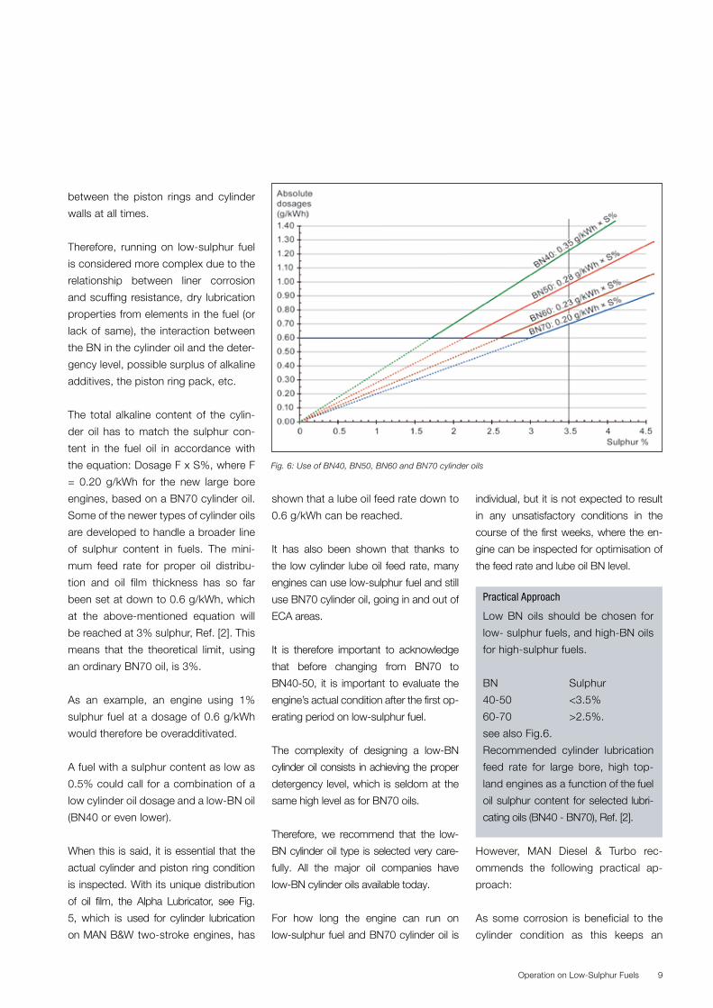
The total alkaline content of the cylin-
der oil has to match the sulphur con-
tent in the fuel oil in accordance with
the equation: Dosage F x S%, where F
= 0.20 g/kWh for the new large bore
engines, based on a BN70 cylinder oil.
Some of the newer types of cylinder oils
are developed to handle a broader line
of sulphur content in fuels. The mini-
mum feed rate for proper oil distribu-
tion and oil film thickness has so far
been set at down to 0.6 g/kWh, which
at the above-mentioned equation will
be reached at 3% sulphur, Ref. [2]. This
means that the theoretical limit, using
an ordinary BN70 oil, is 3%.
As an example, an engine using 1%
sulphur fuel at a dosage of 0.6 g/kWh
would therefore be overadditivated.
A fuel with a sulphur content as low as
0.5% could call for a combination of a
low cylinder oil dosage and a low-BN oil
(BN40 or even lower).
When this is said, it is essential that the
actual cylinder and piston ring condition
is inspected. With its unique distribution
of oil film, the Alpha Lubricator, see Fig.
5, which is used for cylinder lubrication
on MAN B&W two-stroke engines, has
shown that a lube oil feed rate down to
0.6 g/kWh can be reached.
It has also been shown that thanks to
the low cylinder lube oil feed rate, many
engines can use low-sulphur fuel and still
use BN70 cylinder oil, going in and out of
ECA areas.
It is therefore important to acknowledge
that before changing from BN70 to
BN40-50, it is important to evaluate the
engine’s actual condition after the first op-
erating period on low-sulphur fuel.
The complexity of designing a low-BN
cylinder oil consists in achieving the proper
detergency level, which is seldom at the
same high level as for BN70 oils.
Therefore, we recommend that the low-
BN cylinder oil type is selected very care-
fully. All the major oil companies have
low-BN cylinder oils available today.
For how long the engine can run on
low-sulphur fuel and BN70 cylinder oil is
individual, but it is not expected to result
in any unsatisfactory conditions in the
course of the first weeks, where the en-
gine can be inspected for optimisation of
the feed rate and lube oil BN level.
However, MAN Diesel & Turbo rec-
ommends the following practical ap-
proach:
As some corrosion is beneficial to the
cylinder condition as this keeps an
Operation on Low-Sulphur Fuels
Practical Approach
Low BN oils should be chosen for
low- sulphur fuels, and high-BN oils
for high-sulphur fuels.
BN Sulphur
40-50 <3.5%
60-70 >2.5%.
see also Fig.6.
Recommended cylinder lubrication
feed rate for large bore, high top-
land engines as a function of the fuel
oil sulphur content for selected lubri-
cating oils (BN40 - BN70), Ref. [2].
Fig. 6: Use of BN40, BN50, BN60 and BN70 cylinder oils
open graphite lamella structure of the
cylinder liner surface from where the
cylinder lubricant can spread. The pur-
pose is therefore not to avoid corrosion
but to control corrosion. This is done
by adjusting the amount of base, i.e. by
either using BN40 cylinder lube oil (in-
stead of BN70 as normal for operation
on HFO), by optimising the cylinder oil
feed rate to the actual fuel sulphur level
or a combination of both.
For high topland engines (high topland
pistons are pistons where the topland
is significantly higher than the ringland),
MAN Diesel recommends to change to
a BN40 cylinder oil at minimum feed
rate operating for extended periods
(typically more than two weeks) on low
sulphur fuel in e.g. ECAs.
We have reports of older low topland
engines operating continuously on low
sulphur fuels and with BN70 cylinder oil
without problems. In such cases, it is
subject to owner decision whether to
change to a BN40 cylinder oil.
We refer to our service letters Nos.
SL385, SL479 and SL507 for more
information and recommendations on
cylinder oil feed rate for specific engine
types. For future reference, please al-
ways check our latest service letters.
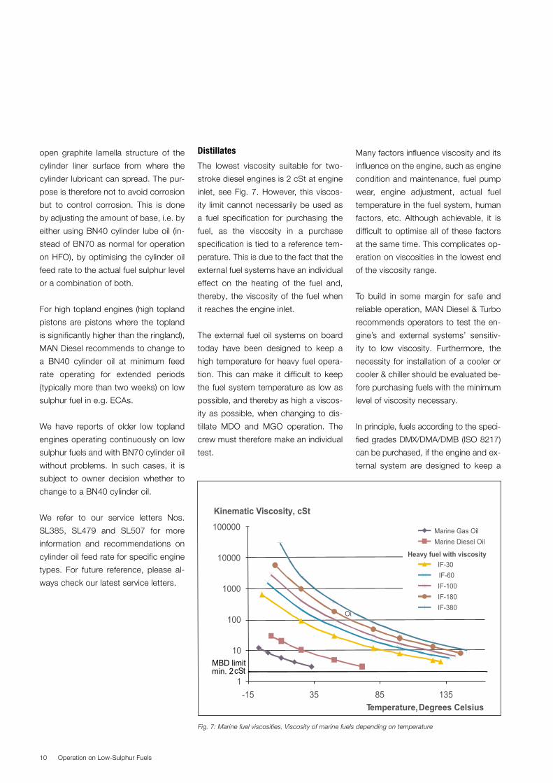
Distillates
The lowest viscosity suitable for two-
stroke diesel engines is 2 cSt at engine
inlet, see Fig. 7. However, this viscos-
ity limit cannot necessarily be used as
a fuel specification for purchasing the
fuel, as the viscosity in a purchase
specification is tied to a reference tem-
perature. This is due to the fact that the
external fuel systems have an individual
effect on the heating of the fuel and,
thereby, the viscosity of the fuel when
it reaches the engine inlet.
The external fuel oil systems on board
today have been designed to keep a
high temperature for heavy fuel opera-
tion. This can make it difficult to keep
the fuel system temperature as low as
possible, and thereby as high a viscos-
ity as possible, when changing to dis-
tillate MDO and MGO operation. The
crew must therefore make an individual
test.
Many factors influence viscosity and its
influence on the engine, such as engine
condition and maintenance, fuel pump
wear, engine adjustment, actual fuel
temperature in the fuel system, human
factors, etc. Although achievable, it is
difficult to optimise all of these factors
at the same time. This complicates op-
eration on viscosities in the lowest end
of the viscosity range.
To build in some margin for safe and
reliable operation, MAN Diesel & Turbo
recommends operators to test the en-
gine’s and external systems’ sensitiv-
ity to low viscosity. Furthermore, the
necessity for installation of a cooler or
cooler & chiller should be evaluated be-
fore purchasing fuels with the minimum
level of viscosity necessary.
In principle, fuels according to the speci-
fied grades DMX/DMA/DMB (ISO 8217)
can be purchased, if the engine and ex-
ternal system are designed to keep a
Operation on Low-Sulphur Fuels10
1
10
100
1000
10000
100000
-15 35 85 135Temperature, Degrees Celsius
Kinematic Viscosity, cSt
Marine Gas OilMarine Diesel Oil
IF-30IF-60 IF-100IF-180IF-380
MBD limitmin. 2cSt
Oi
Heavy fuel with viscosity
Fig. 7: Marine fuel viscosities. Viscosity of marine fuels depending on temperature
11
minimum viscosity of 2 cSt at engine in-
let. If 3 cSt can be obtained, this is pre-
ferred to ensure a higher safety margin.
ISO 8217
According to ISO 8217-2010, distillate
grades DMX/DMA/DMB can be sold
with a viscosity down to 1.4 or 2 cSt at
40°C, respectively. This will especially
be the case if the <2 cSt DMX/DMA
provided origins from automotive gas
oil. The 2 cSt can only be applied if the
distillate is cooled/chilled down corre-
spondingly to reach the 2 cSt minimum
viscosity at engine inlet.
The latest distillate introduced in ISO
8217-2010 is DMZ with min. 3 cSt at
40°C, which gives some margin.
Influence of fuel lubricity and
viscosity at engine inlet
Lubricity
The refinery processes intended to re-
move, e.g., sulphur from the oil result
not only in low viscosity, but also im-
pacts the lubricity enhancing compo-
nents of the fuel. Too little lubricity may
result in fuel pump seizures.
Although most refiners add lubricity-
enhancing additives to distillates, MAN
Diesel & Turbo recommends testing
the lubricity before using fuels with less
than 0.05% sulphur. Independent fuel
laboratories can test lubricity accord-
ing to ISO 12156-1 (High-Frequency
Reciprocating Rig, HFRR). The HFRR
wear scar limit is max. 520 μm.
Operation on Low-Sulphur Fuels
01 2 3 4
Viscosity (cSt)
Fuel
Tem
p (d
eg C
)
5 6 7 8
20
40
60
80
100
120
140
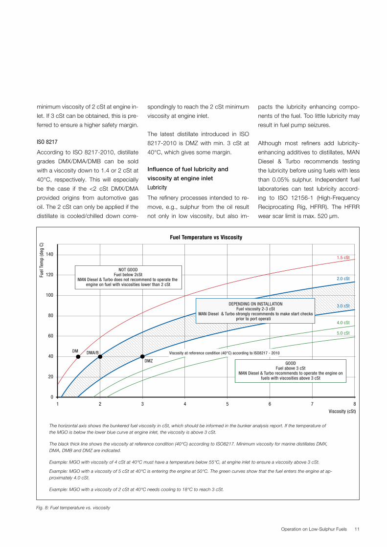
NOT GOODFuel below 2cSt
MAN Diesel & Turbo does not recommend to operate the engine on fuel with viscosities lower than 2 cSt
Viscosity at reference condition (40°C) according to ISO8217 - 2010
DEPENDING ON INSTALLATIONFuel viscosity 2-3 cSt
MAN Diesel & Turbo strongly recommends to make start checksprior to port operation
1.5 cSt
2.0 cSt
3.0 cSt
4.0 cSt
5.0 cSt
Fuel Temperature vs Viscosity
DM
DMZ
DMA/B
GOODFuel above 3 cSt
MAN Diesel & Turbo recommends to operate the engine onfuels with viscosities above 3 cSt
Fig. 8: Fuel temperature vs. viscosity
The horizontal axis shows the bunkered fuel viscosity in cSt, which should be informed in the bunker analysis report. If the temperature of the MGO is below the lower blue curve at engine inlet, the viscosity is above 3 cSt.
The black thick line shows the viscosity at reference condition (40°C) according to ISO8217. Minimum viscosity for marine distillates DMX, DMA, DMB and DMZ are indicated.
Example: MGO with viscosity of 4 cSt at 40°C must have a temperature below 55°C, at engine inlet to ensure a viscosity above 3 cSt.
Example: MGO with a viscosity of 5 cSt at 40°C is entering the engine at 50°C. The green curves show that the fuel enters the engine at ap-proximately 4.0 cSt.
Example: MGO with a viscosity of 2 cSt at 40°C needs cooling to 18°C to reach 3 cSt.
So far, we have not had a single report
of lucbricity-related problems. However,
as the market will shift towards running
on more distillates, we might see pure
marine distillates on the market. These
fuels might be without in-land, automa-
tive lubricity additives or bio fuels. To
test our equipment ability to run on this
type of fuel, we are planning a test on
a low viscosity, low sulphur, low lubric-
ity type of fuel. The test will include our
standard fuel equipment and a special
non-stick coating.
Viscosity
A low-viscosity fuel oil challenges the
function of the pump in three ways:
1. Breakdown of hydrodynamic oil film
(resulting in seizures),
2. Insufficient injection pressure (re-
sulting in difficulties during start and
low-load operation), and
3. Insufficient fuel index margin (re-
sulting in limitation in acceleration).
We have tested our standard equip-
ment ability to run on very low viscosity
fuel in our in-house test rigs.
The tests confirmed the robustness
in our equipment running on the fuels
available on the market today.
Due to the design of conventional
pumps versus the pressure booster,
ME/ME-C/ME-B engines are more tol-
erant towards a low viscosity compared
with the MC/MC-C engines.
Many factors influence the viscosity
tolerance during start and low-load op-
eration:
� Engine condition and maintenance
� Fuel pump wear
� Engine adjustment
� Actual fuel temperature in the fuel
system
� Human factors, etc.
Although achievable, it is difficult to op-
timise all of these factors at the same
time. This complicates operation on
viscosities in the lowest end of the vis-
cosity range. To build in some margin
for safe and reliable operation, and
availability of high-viscosity distillate
fuels, it is expected that installation of
coolers or cooler & chiller will be neces-
sary for many operators.
Fuel oil pump pressure
Worn fuel pumps increase the risk of
starting difficulties, as the fuel oil pump
pressure needed for injection cannot
be achieved. An indication of fuel pump
wear can be achieved by reading the
actual fuel pump index for comparison
with the test bed measurements. As a
rough guideline, we consider the pump
worn out when the index increase is 10
or more for heavy fuel. Such fuel pumps
should be replaced for better engine
performance.
Start checks are always recommeded to
be done at regular intervals. However, as
distillates of required minimum viscosity
may not be available in all ports, it is par-
ticurlarly important to make start checks
before entering high-risk areas (e.g. ports
and other congested areas), so as to
determine the individual low-viscosity
limit for the engine. MAN Diesel & Turbo
recommends that such checks are perfo-
med on a biannual basis, as described in
the following:
� In an area for safe operation, change
fuel to an available distillate.
� At different operating conditions,
e.g. start, idle, astern and steady low
rpm, gradually change the tempera-
ture of the fuel at engine inlet, corre-
sponding to respectively 2, 2.5 and 3
cSt, see Fig. 8 for the typical viscos-
ity and temperature relationship.
� Test start ahead/astern from the
control room. If the engine does not
start at the first attempt, cancel and
repeat the start attempt. If the start
ahead/astern functions properly with
cancelled limiter, this solution can be
used in emergency until either new
fuel pumps are installed or a higher
viscosity fuel becomes available.
An outcome of the test might be that
the specific engine requires a viscosity
that cannot be kept due to the influence
from the many factors. If the fuel pumps
are worn, they must be replaced and
the start check repeated.
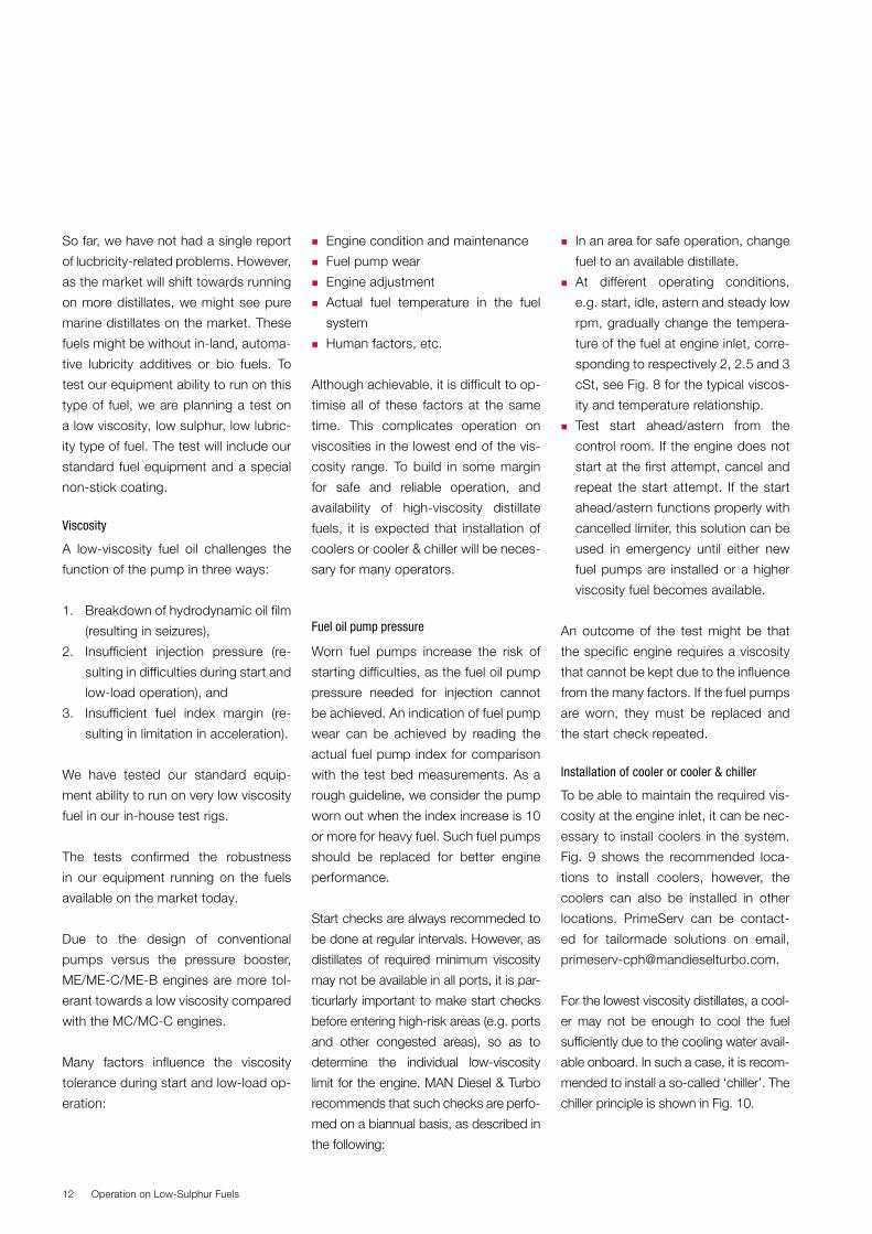
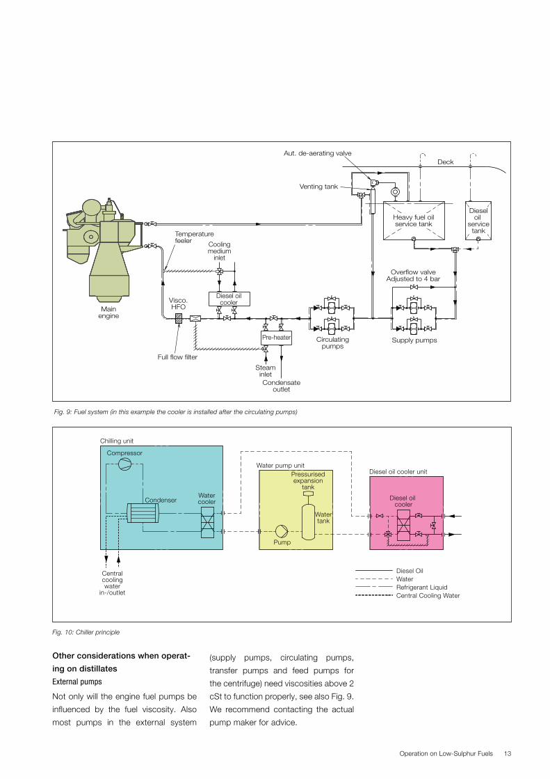
Installation of cooler or cooler & chiller
To be able to maintain the required vis-
cosity at the engine inlet, it can be nec-
essary to install coolers in the system.
Fig. 9 shows the recommended loca-
tions to install coolers, however, the
coolers can also be installed in other
locations. PrimeServ can be contact-
ed for tailormade solutions on email,
For the lowest viscosity distillates, a cool-
er may not be enough to cool the fuel
sufficiently due to the cooling water avail-
able onboard. In such a case, it is recom-
mended to install a so-called ‘chiller’. The
chiller principle is shown in Fig. 10.
Operation on Low-Sulphur Fuels12
13
Other considerations when operat-
ing on distillates
External pumps
Not only will the engine fuel pumps be
influenced by the fuel viscosity. Also
most pumps in the external system
(supply pumps, circulating pumps,
transfer pumps and feed pumps for
the centrifuge) need viscosities above 2
cSt to function properly, see also Fig. 9.
We recommend contacting the actual
pump maker for advice.
Operation on Low-Sulphur Fuels
Mainengine
Heavy fuel oilservice tank
Dieseloil
servicetank
Deck
Diesel oilcooler
Circulatingpumps
Supply pumps
Aut. de-aerating valve
Venting tank
Full flow filter
Pre-heater
Visco.HFO
SteaminletCondensate
outlet
Coolingmedium
inlet
Temperaturefeeler
Overflow valveAdjusted to 4 bar
Fig. 9: Fuel system (in this example the cooler is installed after the circulating pumps)
Fig. 10: Chiller principle
Compressor
Chilling unit
Water pump unitPressurisedexpansion
tank
Diesel oil cooler unit
Diesel oil cooler
Diesel Oil WaterRefrigerant LiquidCentral Cooling Water
Watertank
WatercoolerCondenser
Centralcoolingwater
in-/outlet
Pump
� It has been experienced from many
ships that the circulation and supply
pumps installed in the external fuel
system have troubles in keeping the
pressure if viscosity is too low. Some
pumps need 5 cSt, which is far from
the 2 cSt specified at engine inlet
when operating on distillates. MAN
Diesel & Turbo has been in contact
with pump manufacturers that can
deliver external pumps for fuels with
viscosities below 2 cSt. Our Engine
and System Application department
in Copenhagen can be contacted for
further information.
� Poor point restrictions: Distillates
should not be cooled below 10°C
above the pour point.
The poor point is a rough estimate for
the lowest temperature at which the
fuel will flow and be readily pumpable.
Change-over between heavy fuel
and distillates
For specific change-over procedure,
reference is made to our general in-
struction for changing over from heavy
fuel to distillate and back in our Opera-
tion Book plate 4245-0120-0003 (older
manual: Plate 705-03).
Before the intended change-over, we
recommend checking
� The compatibility of the two fuels –
preferably at the bunkering stage
� The wear in the fuel pumps, as leak-
age will increase when operating on
low-viscosity fuel
Change-over of fuel can be somewhat
harmful for the fuel equipment, because
relatively cold distillate is mixed with
hot heavy fuel. The process therefore
needs careful monitoring of tempera-
ture and viscosity and during change-
over two factors are to be kept under
observation:
� The viscosity must not drop below 2
cSt and not exceed 20 cSt
� The rate of temperature change of
the fuel inlet to the fuel pumps must
not exceed 2°C/min to protect the
fuel equipment from thermal shock.
Special care must be taken when oper-
ating fuel heater and cooler that above
mentioned limits are not exceeded. Au-
tomatic operation also has to be kept
under observation for correct and safe
operation.
The engine load must be reduced dur-
ing the change-over procedure. We
recommend 25-40% load to ensure
a slow reduction of the temperature.
The load can – based on experience –
be changed to a higher level – up to
75% load as described in our Opera-
tion Book. For operational assistance,
please contact our LEO……???
A change-over of the main engine’s
fuel will result in a dilution of the fuel
already in the booster circuit. A com-
plete change of fuel (e.g. only distillate
in the system) can therefore take sev-
eral hours, depending on engine load,
system layout and volume of fuel in the
booster-circuit. Change-over can be
confirmed by taking a fuel sample at
main engine inlet.
Operation on Low-Sulphur Fuels14
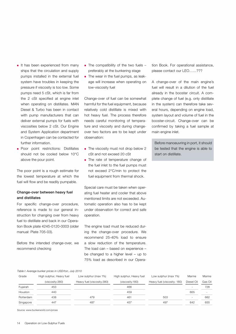
Table I: Average bunker prices in USD/ton, July 2010
Grade High sulphur, Heavy fuel
(viscosity:380)
Low sulphur (max 1%)
Heavy fuel (viscosity: 380)
High sulphur, Heavy fuel
(viscosity:180)
Low sulphur (max 1%)
Heavy fuel (viscosity: 180)
Marine
Diesel Oil
Marine
Gas Oil
Fujairah 453 466 - 728
Houston 440 459 665 -
Rotterdam 438 479 461 503 - 662
Singapore 447 487 457 497 642 655
Source: www.bunkerworld.com/prices
Before manoeuvring in port, it should
be tested that the engine is able to
start on distillate.
15
Ignition and Combustion Characteristics of Low-Sulphur Fuels
The interest in fuel oils’ ignition quality on
the basis of the calculated CCAI or CCI
values, or by measuring the fuel in an
ignition instrument such as the FIA (Fuel
Ignition Analyser), has never, in our ex-
perience, been greater than now. In the
CIMAC Heavy Fuel Oil Work Group, we
have compared fuel samples and ser-
vice experience and, today, there are
definitely more reports of cases where
a poor liner and piston ring condition
is thought to be due to a low ignition
quality. The investigations indicate that
a low-sulphur fuel has often been used
when this happens, and the question is
whether new oils from the spot market
have characteristics which have so far
been overlooked and, therefore, ought
to be investigated further.
When focus is narrowly on the fuel oils,
the drawback can be that some opera-
tors, when experiencing unacceptable
conditions in the combustion chamber,
may be prompted to blame the fuel
without taking other possible causes
into consideration, such as insufficient
cleaning of the fuel oil, type of cylinder
lube oil and feed rate.
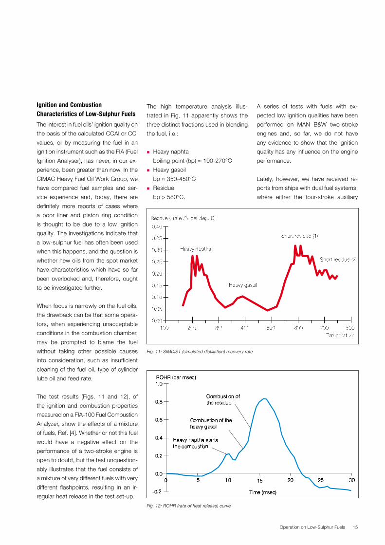
The test results (Figs. 11 and 12), of
the ignition and combustion properties
measured on a FIA-100 Fuel Combustion
Analyzer, show the effects of a mixture
of fuels, Ref. [4]. Whether or not this fuel
would have a negative effect on the
performance of a two-stroke engine is
open to doubt, but the test unquestion-
ably illustrates that the fuel consists of
a mixture of very different fuels with very
different flashpoints, resulting in an ir-
regular heat release in the test set-up.
The high temperature analysis illus-
trated in Fig. 11 apparently shows the
three distinct fractions used in blending
the fuel, i.e.:
� Heavy naphta
boiling point (bp) ≈ 190270°C
� Heavy gasoil
bp ≈ 350450°C
� Residue
bp > 580°C.
A series of tests with fuels with ex-
pected low ignition qualities have been
performed on MAN B&W two-stroke
engines and, so far, we do not have
any evidence to show that the ignition
quality has any influence on the engine
performance.
Lately, however, we have received re-
ports from ships with dual fuel systems,
where either the four-stroke auxiliary
Operation on Low-Sulphur Fuels
Fig. 12: ROHR (rate of heat release) curve
Fig. 11: SIMDIST (simulated distillation) recovery rate
engines were difficult to operate, or
damage to the combustion chamber
was found.
One step was taken in 2009 when in-
terested companies formed a group
that could provide for the definition and
measurements of ignition and combus-
tion characteristics of residual fuels in
a standardised approach, with the aim
of producing IP (Institute of Petroleum)
test methods.
The group is looking particularly at the
FIA test methods which, to our knowl-
edge, are so far the best methods for
such analyses. But the question is
whether it is possible to translate the
test results into engine performance.
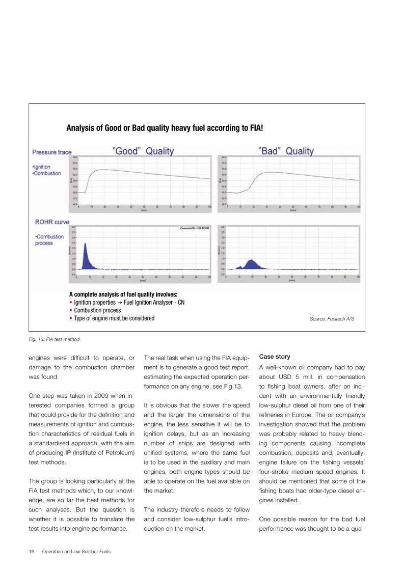
The real task when using the FIA equip-
ment is to generate a good test report,
estimating the expected operation per-
formance on any engine, see Fig.13.
It is obvious that the slower the speed
and the larger the dimensions of the
engine, the less sensitive it will be to
ignition delays, but as an increasing
number of ships are designed with
unified systems, where the same fuel
is to be used in the auxiliary and main
engines, both engine types should be
able to operate on the fuel available on
the market.
The industry therefore needs to follow
and consider low-sulphur fuel’s intro-
duction on the market.
Case story
A well-known oil company had to pay
about USD 5 mill. in compensation
to fishing boat owners, after an inci-
dent with an environmentally friendly
low-sulphur diesel oil from one of their
refineries in Europe. The oil company’s
investigation showed that the problem
was probably related to heavy blend-
ing components causing incomplete
combustion, deposits and, eventually,
engine failure on the fishing vessels’
four-stroke medium speed engines. It
should be mentioned that some of the
fishing boats had older-type diesel en-
gines installed.
One possible reason for the bad fuel
performance was thought to be a qual-
Operation on Low-Sulphur Fuels16
Fig. 13: FIA test method
Analysis of Good or Bad quality heavy fuel according to FIA!
A complete analysis of fuel quality involves: Ignition properties → Fuel Ignition Analyser - CN Combustion process Type of engine must be considered Source: Fueltech A/S
17
ity slip during operation of the desul-
phurisation unit, and the oil company
had to adjust the process in conse-
quence of this incident.
The important message to the fuel
companies is, consequently, that low-
sulphur fuels must not jeopardise the
operational reliability of the engine.
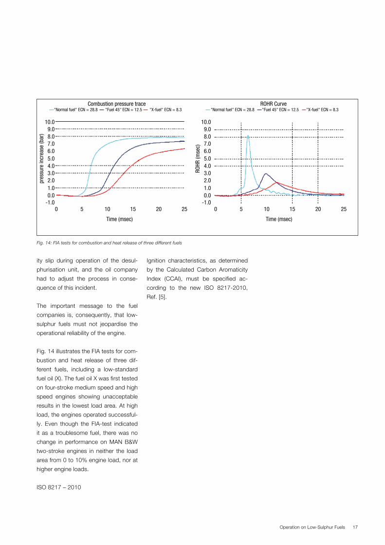
Fig. 14 illustrates the FIA tests for com-
bustion and heat release of three dif-
ferent fuels, including a low-standard
fuel oil (X). The fuel oil X was first tested
on four-stroke medium speed and high
speed engines showing unacceptable
results in the lowest load area. At high
load, the engines operated successful-
ly. Even though the FIA-test indicated
it as a troublesome fuel, there was no
change in performance on MAN B&W
two-stroke engines in neither the load
area from 0 to 10% engine load, nor at
higher engine loads.
ISO 8217 – 2010
Ignition characteristics, as determined
by the Calculated Carbon Aromaticity
Index (CCAI), must be specified ac-
cording to the new ISO 8217-2010,
Ref. [5].
Operation on Low-Sulphur Fuels
Fig. 14: FIA tests for combustion and heat release of three different fuels
ROHR Curve "Normal fuel" ECN = 28.8 "Fuel 45" ECN = 12.5 "X-fuel" ECN = 8.3
0-1.00.01.02.03.04.05.0
pres
sure
incr
ease
(bar
)
6.07.08.09.0
10.0
-1.00.01.02.03.04.05.0
ROHR
(mse
c)
6.07.08.09.0
10.0
5 10 15 20 25 0 5 10 15 20 25
Combustion pressure trace "Normal fuel" ECN = 28.8 "Fuel 45" ECN = 12.5 "X-fuel" ECN = 8.3
Time (msec) Time (msec)
Fuel Oil Auxiliary Systems
As low-sulphur fuel oil is more expensive,
the higher sulphur fuel oil is preferred
where accepted to be used. To enable
the vessel to operate on low-sulphur fuel
in restricted areas and switch to heavy
fuel outside restricted areas, a dual fuel
system is necessary.
For newbuildings, and as retrofit on ex-
isting engines if necessary, MAN Diesel
& Turbo proposes three different fuel
system configurations for engines op-
erating on both high and low-sulphur
fuel oils.
The ship’s fuel oil system, from bunker-
ing tanks through the settling tanks,
treatment system and service tanks, may
be affected by a frequent change in fuel
oil type. Therefore, depending on the
changeover frequency, various config-
urations may be relevant, the principal
ones being listed below:
Fuel oil system, No. 1 (Fig. 15)
One MDO + one HFO system:
One bunkering, settling, centrifuging
and service tank system for MDO, and
one for HFO. Often several separate
bunker tanks (heated) are available in
the ship, enabling use of different bun-
ker oils. Systems are merged before the
pressurising (supply) stage leading to
the engine circulating system. Auxiliary
engines are usually fed from the joined
systems, i.e. they burn the same fuels
as the main engine. Also referred to as
the “Unifuel” concept. It is possible to
run the auxiliary engines on a separate
fuel, i.e. by closing off the line from the
HFO system to the auxiliary engines.
Fuel oil system, No. 2 (Fig. 16)
One MDO + two HFO settling tanks:
One bunkering and settling system for
each type of HFO. Possibly with addi-
tional bunker tanks. The HFO system is
common from centrifuge(s) onwards,
i.e. it is identical to fuel oil system No. 1,
but with an additional settling tank for
alternate HFO types. Unifuel or sepa-
rate fuel.
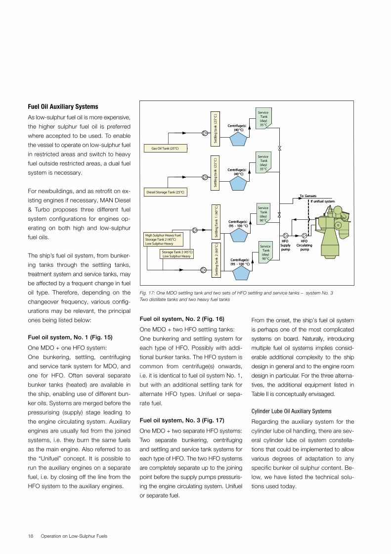
Fuel oil system, No. 3 (Fig. 17)
One MDO + two separate HFO systems:
Two separate bunkering, centrifuging
and settling and service tank systems for
each type of HFO. The two HFO systems
are completely separate up to the joining
point before the supply pumps pressuris-
ing the engine circulating system. Unifuel
or separate fuel.
From the onset, the ship’s fuel oil system
is perhaps one of the most complicated
systems on board. Naturally, introducing
multiple fuel oil systems implies consid-
erable additional complexity to the ship
design in general and to the engine room
design in particular. For the three alterna-
tives, the additional equipment listed in
Table II is conceptually envisaged.
Cylinder Lube Oil Auxiliary Systems
Regarding the auxiliary system for the
cylinder lube oil handling, there are sev-
eral cylinder lube oil system constella-
tions that could be implemented to allow
various degrees of adaptation to any
specific bunker oil sulphur content. Be-
low, we have listed the technical solu-
tions used today.
Operation on Low-Sulphur Fuels18
Fig. 17: One MDO settling tank and two sets of HFO settling and service tanks – system No. 3 Two distillate tanks and two heavy fuel tanks
ServiceTank(day)35°C
ServiceTank(day)90°C
Centrifuge(s(40 °C)
Centrifuge(s(95 - 100 °C)
ServiceTank(day)90°CCentrifuge(s
(95 - 100 °C)
HFOSupplypump
HFOCirculating
pump
If unifuel system
To GensetsMDO Storage Tank (25 °C)
Set
tling
Tank
(25°
C)
Set
tling
ank
1(6
0°C
)S
ettli
ngan
k2
(60°
C)
TT
ServiceTank(day)35°C
ServiceTank(day)90°C
Centrifuge(s)(40 °C)
Centrifuge(s)(95 - 100 °C)
ServiceTank(day)90°CCentrifuge(s)
(95 - 100 °C)
HFOSupplypump
HFOCirculating
pump
If unifuel system
To GensetsMDO Storage Tank (25 °C)
Set
tling
Tank
(25°
C)
Set
tling
ank
1(6
0°C
)S
ettli
ngan
k2
(60°
C)
TT
Diesel Storage Tank (25°C)
Settl
ing
Tank
(25°
C)
Settl
ing
ank
1(6
0°C
)
Storage Tank 2 (45°C) Low Sulphur Heavy
Sett
ling
ank
2(6
0°C
)T
T
ServiceTank(day)35°CCentrifuge(s
(40 °C)
Set
tling
Tank
(25°
C) Service
Tank(day)35°CCentrifuge(s)
(40 °C)
Set
tling
Tank
(25°
C)
Settl
ing
Tank
(25°
C)
°° High Sulphur Heavy Fuel Storage Tank 2 (45°C) Low Sulphur Heavy
MDO Storage Tank (25 °C)MDO Storage Tank (25 °C)Gas Oil Tank (25°C)
19
Cylinder oil system, No. 1 (Fig. 18)
One cylinder oil system:
A conventional system that can han-
dle one cylinder lube oil at a time, i.e.
running with a fixed base number. The
feed rate can be manually controlled
and is seldom adjusted.
Cylinder oil system, No. 2 (Fig. 19)
One cylinder oil system where the en-
gine is equipped with electronic Alpha
lubricators:
Also ability to handle one cylinder lube
oil at a time, i.e. running with a fixed base
number. The electronic lubricator (very
much) eases the adjustment of feed rate
and, thereby, the alkalinity influx.
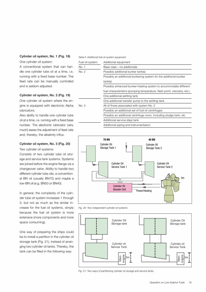
Cylinder oil system, No. 3 (Fig. 20)
Two cylinder oil systems:
Consists of two cylinder lube oil stor-
age and service tank systems. Systems
are joined before the engine flange via a
changeover valve. Ability to handle two
different cylinder lube oils, a convention-
al BN oil (usually BN70) and maybe a
low-BN oil (e.g. BN50 or BN40).
In general, the complexity of the cylin-
der lube oil system increases 1 through
3, but not as much as the similar in-
crease for the fuel oil systems, simply
because the fuel oil system is more
extensive (more components and more
space consuming).
One way of preparing the ships could
be to install a partition in the cylinder oil
storage tank (Fig. 21), instead of arran-
ging two cylinder oil tanks. Thereby, the
tank can be filled in the following way:
Operation on Low-Sulphur Fuels
Fuel oil system: Additional equipment
No. 1 Base case – no additionals
No. 2
Possibly additional bunker tank(s)
Possibly an additional bunkering system for the additional bunker
tank(s)
Possibly enhanced bunker-heating system to accommodate different
fuel characteristics (pumping temperature, flash point, viscosity, etc.)
One additional settling tank
One additional transfer pump to the settling tank
No. 3
All of those associated with system No. 2
Possibly an additional set of fuel oil centrifuges
Possibly an additional centrifuge room, including sludge tank, etc
Additional service (day) tank
Additional piping and instrumentation
Fig. 20: Two independent cylinder oil systems
Fig. 21: Two ways of partitioning cylinder oil storage and service tanks
Cylinder OilStorage Tank 1
Cylinder OilService Tank 1
Cylinder OilStorage Tank 2
Cylinder OilService Tank 2
3m
OilUnit Power/Heating
OilUnit
70 BN 40 BN
CylinderBoosterCylinderBoosterCylinder OilBooster Unit
Table II: Additional fuel oil system equipment
� BN70 cylinder oil on both sides of
the partition
� BN40 cylinder oil on one side and
BN70 on the other.
In the more complex system, separate
piping from each side of the partitioned
storage tank can lead to the service
tank, which may also be partitioned.
The systems shown can be combined
in numerous ways, and variations of the
described systems can be chosen. You
are welcome to contact MAN Diesel &
Turbo in Copenhagen, Denmark, for
special requirements, or if further infor-
mation is needed.
Experience with Wet Scrubbing Techniques and Expectations to Future Use
As previously described, one solution
to meet the sulphur legislation is to re-
duce the SOx in the exhaust gas. The
so-called abatement technology used
for many years on power stations all
over the world.
Even though scrubbers are not a core
business of MAN Diesel & Turbo, six
years ago we initiated cooperation with
manufacturers and shipowners to look
at this technique for the marine market.
Accordingly, we have made more than
170 tests of scrubbers of various de-
signs on a 1 MW four-stroke engine in
Denmark.
The first results obtained made it clear
that current scrubber techniques need
to be optimised and tailormade for ma-
rine use.
To begin with, saltwater was used as
the agent for removing SOx from the ex-
haust gas. Later, freshwater with NaOH
was used and both techniques work.
On an Aalborg Industries (AI) boiler, SOx
could not even be measured in the ex-
haust gas after the scrubbing process
with freshwater and NaOH.
This solution seems to be superior to
the saltwater solution when it comes to
efficiency and the amount of drain and
process water, but it will have a con-
sumption of NaOH.
In 2009, an AI scrubber was installed
on a DFDS passenger and car carrier
with a 20 MW main engine. The scrub-
ber is able to operate on both saltwater
and freshwater with NaOH and the long-
term service tests show promising re-
sults.
The plan is to operate the scrubber in
the high-efficient NaOH-mode in coast-
al areas and in saltwater mode when in
open sea, where a lower scrubbing ef-
ficiency is required.
This could give the lowest payback
time, which for this vessel could be as
low as two years, depending on the de-
velopment in fuel prices.
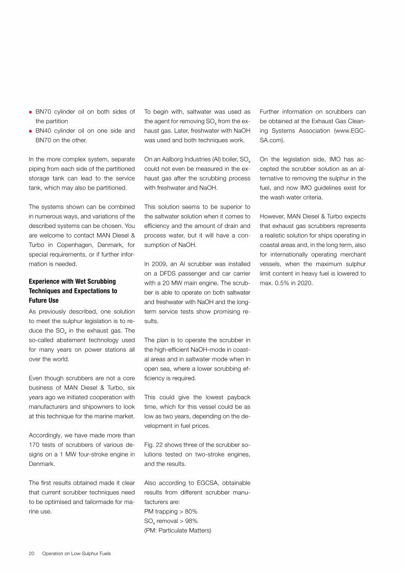
Fig. 22 shows three of the scrubber so-
lutions tested on two-stroke engines,
and the results.
Also according to EGCSA, obtainable
results from different scrubber manu-
facturers are:
PM trapping > 80%
SOx removal > 98%
(PM: Particulate Matters)
Further information on scrubbers can
be obtained at the Exhaust Gas Clean-
ing Systems Association (www.EGC-
SA.com).
On the legislation side, IMO has ac-
cepted the scrubber solution as an al-
ternative to removing the sulphur in the
fuel, and now IMO guidelines exist for
the wash water criteria.
However, MAN Diesel & Turbo expects
that exhaust gas scrubbers represents
a realistic solution for ships operating in
coastal areas and, in the long term, also
for internationally operating merchant
vessels, when the maximum sulphur
limit content in heavy fuel is lowered to
max. 0.5% in 2020.
Operation on Low-Sulphur Fuels20
21
Summary
It is inevitable that the exhaust gas
emission from marine engines will be
further regulated, and we expect that
many new engines, and especially ex-
isting engines, will eventually have to be
operated on low-sulphur fuel.
On MAN B&W two-stroke engines, no
difference in the engine performance
is considered between distillate and
heavy fuel operation. However, opera-
tors must take the necessary precau-
tions and follow our service instructions
Abbreviations
ECA: Emission Controlled Areas
BN: Base Number
TBN: Total Base Number
CCAI: Calculated Carbon Aromatic-
ity Index
CCI:
FIA: Fuel Ignition Analyser
IP: Institute of Petroleum
PM: Particulate Matter
IMO: International Maritime Organi-
sation
CARB: California Air Resources Board
MFO: Heavy Fuel Oil
MDO: Marine Diesel Oil
MGO: Marine Gas Oil
SOx: Sulphur oxides
NOx: Nitrogen oxides
HC: Hydrocabons
CO: Carbon monoxide
CO2: Carbon dioxide
References
[1] Service Letter SL09-515 "Guide-
lines on Operation on Distillate
Fuels"
[2] Service Letter SL09-507 "Cylinder
Lubrication Update – Guiding ACC
Feed Rates for Alpha Lubricator
and ME Lube"
[3] “FIA-100 – Fuel Combustion
Analyzer for HFO”, by Jan Kjetil
Paulsen, Fueltech AS, Norway,
November 2004
[4] ISO 8217-2010 Petroleum Pro-
ducts - Fuels (class F) - Spe-
cifications of marine fuels,
Fourth edition, 2010-06-15.
Operation on Low-Sulphur Fuels
Fig.22: Scrubber solutions tested


MAN Diesel & TurboTeglholmsgade 41
2450 Copenhagen SV, Denmark
Phone +45 33 85 11 00
Fax +44 33 85 10 30
www.mandieselturbo.com
MAN Diesel & TurboTeglholmsgade 412450 Copenhagen SV, DenmarkPhone +45 33 85 11 00Fax +45 33 85 10 [email protected]
MAN Diesel & Turbo – a member of the MAN Group
All data provided in this document is non-binding. This data serves informational purposes only and is especially not guaranteed in any way. Depending on the subsequent specific individual projects, the relevant data may be subject to changes and will be assessed and determined individually for each project. This will depend on the particular characteristics of each individual project, especially specific site and operational conditions. Copyright © MAN Diesel & Turbo. 5510-0075-01ppr Sep 2014 Printed in Denmark


![Lubricating Aspects of Automotive Fuels - InTech - Open · 2012-08-01 · Lubricating Aspects of Automotive Fuels 93 [1-7]. A survey of low sulphur diesel fuels (sulphur content ranged](https://img.pdfslide.us/doc/110x75/5e99e9b8a80a642a3c4374cc/lubricating-aspects-of-automotive-fuels-intech-open-2012-08-01-lubricating.jpg)