Embed Size (px)
Citation preview
Multidisciplinary International Research Journal of Gujarat Technological University ISSN: 2581-8880
VOLUME 3 ISSUE 1 JANUARY 2021 74
OPERATION OF REGENERATIVE BRAKING IN ELECTRICAL
VEHICLES AND COMPARISON WITH CONVENTIONAL BRAKING
Mihir Barpande
G H Patel College of Engineering & Technology
ABSTRACT
Braking is the primary and fundamental feature of a vehicle. It can be regarded as one of the important
and primary things, and so it’s important to have efficient braking system. The mechanical braking
system which is the most used braking system is sometimes inefficient and its one of the limitations is
that the kinetic energy of the vehicle that is produced after braking is wasted as heat and thus this
phenomenon leads to reducing the efficiency by majorly affecting the fuel and the optimization of fuel.
In, the city areas and the areas having dense population it’s necessary to apply brake every time and
thus decreasing the efficiency of motor. This makes the energy loss wider and thus we need effective
braking system. So, engineers have invented “REGENERATIVE BRAKING SYSTEM” to regain
the kinetic energy that is lost as heat during the old braking method. But, by the law of physics though
we can’t recoup the whole energy but notable amount can be recovered and can be stored in the battery
or super-capacitor.
Keywords: Regenerative braking, electric vehicles, kinetic energy, working.
1.) OBJECTIVES AND METHODOLOGY
1.1) INTRODUCTION
The notion of the regenerative braking which is enacted in day-to-day vehicles is used with the help of
fly-wheels. So, basically fly-wheels are the disks that are with high inertia and it rotates at a high speed.
Thus, we can say that it behaves as a device or container which can store the dissipated kinetic energy
of the vehicle during the process or time of braking. The, residual energy which is stored can be used
for assisting the vehicle during load or the slopes having the up-hill moment.
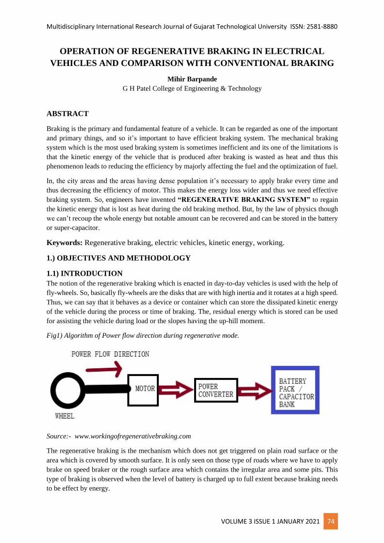
Fig1) Algorithm of Power flow direction during regenerative mode.
Source:- www.workingofregenerativebraking.com
The regenerative braking is the mechanism which does not get triggered on plain road surface or the
area which is covered by smooth surface. It is only seen on those type of roads where we have to apply
brake on speed braker or the rough surface area which contains the irregular area and some pits. This
type of braking is observed when the level of battery is charged up to full extent because braking needs
to be effect by energy.
Multidisciplinary International Research Journal of Gujarat Technological University ISSN: 2581-8880
VOLUME 3 ISSUE 1 JANUARY 2021 75
In EV’s (electrical vehicles) we can assimilate this braking system in more effective way with the use
of electronics and thus reducing the need of heavy fly-wheels, nor it will add to the extra weight of
vehicle. At the process of breaking the amount of kinetic energy that is lost can be re-converted to
electrical energy and can be stored in battery or ultra -capacitor. Thus, by saving the energy we can
control the energy loss and can use it whenever we want by again converting to mechanical energy at
the time of load gaining or load taking by the car or any other vehicle.
1.2) FUNCTIONAL PRINCIPLE OF REGENERATIVE BRAKING
Regenerative braking method uses the mechanical energy which it gets from the motor and converts
electrical energy and it flows back to the battery. There are instances when we need to stop the car or
slow down the car and when we apply the force to apply brakes, the motor present there starts working
in the reverse direction and thus leading to stop the car ultimately. For an instance it is very primary
thing to know that when motor runs in the opposite direction of validate it acts and works as generator.
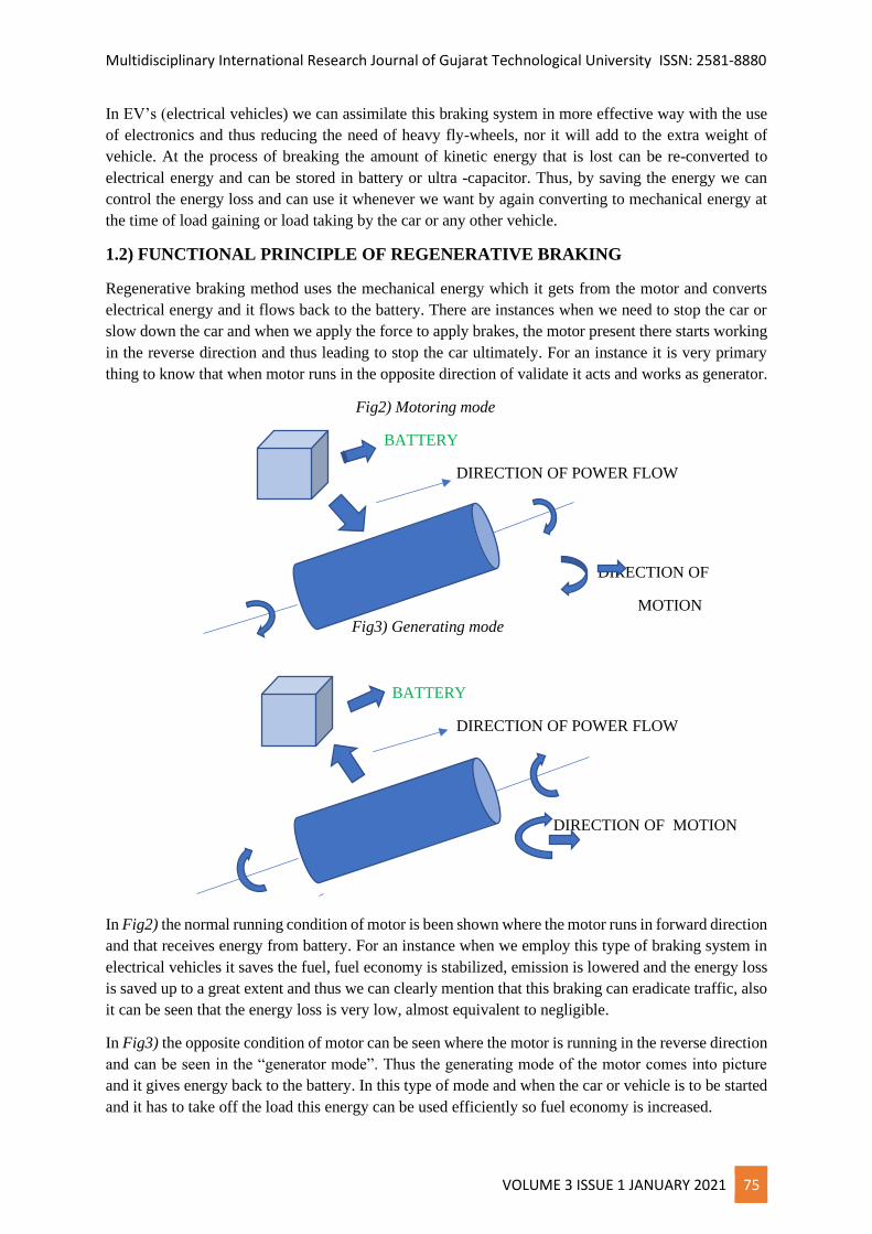
Fig2) Motoring mode
BATTERY
DIRECTION OF POWER FLOW
DIRECTION OF
MOTION
Fig3) Generating mode
BATTERY
DIRECTION OF POWER FLOW
DIRECTION OF MOTION
In Fig2) the normal running condition of motor is been shown where the motor runs in forward direction
and that receives energy from battery. For an instance when we employ this type of braking system in
electrical vehicles it saves the fuel, fuel economy is stabilized, emission is lowered and the energy loss
is saved up to a great extent and thus we can clearly mention that this braking can eradicate traffic, also
it can be seen that the energy loss is very low, almost equivalent to negligible.
In Fig3) the opposite condition of motor can be seen where the motor is running in the reverse direction
and can be seen in the “generator mode”. Thus the generating mode of the motor comes into picture
and it gives energy back to the battery. In this type of mode and when the car or vehicle is to be started
and it has to take off the load this energy can be used efficiently so fuel economy is increased.
Multidisciplinary International Research Journal of Gujarat Technological University ISSN: 2581-8880
VOLUME 3 ISSUE 1 JANUARY 2021 76
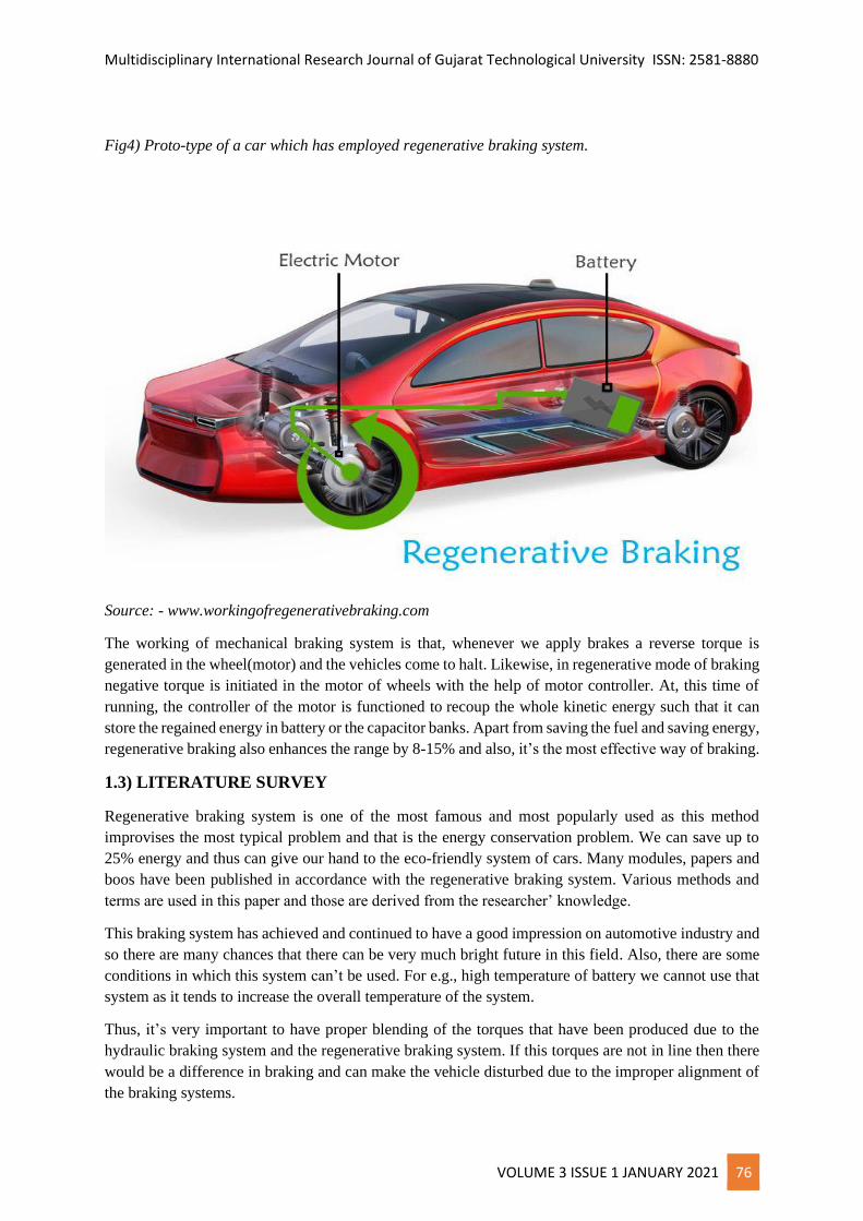
Fig4) Proto-type of a car which has employed regenerative braking system.
Source: - www.workingofregenerativebraking.com
The working of mechanical braking system is that, whenever we apply brakes a reverse torque is
generated in the wheel(motor) and the vehicles come to halt. Likewise, in regenerative mode of braking
negative torque is initiated in the motor of wheels with the help of motor controller. At, this time of
running, the controller of the motor is functioned to recoup the whole kinetic energy such that it can
store the regained energy in battery or the capacitor banks. Apart from saving the fuel and saving energy,
regenerative braking also enhances the range by 8-15% and also, it’s the most effective way of braking.
1.3) LITERATURE SURVEY
Regenerative braking system is one of the most famous and most popularly used as this method
improvises the most typical problem and that is the energy conservation problem. We can save up to
25% energy and thus can give our hand to the eco-friendly system of cars. Many modules, papers and
boos have been published in accordance with the regenerative braking system. Various methods and
terms are used in this paper and those are derived from the researcher’ knowledge.
This braking system has achieved and continued to have a good impression on automotive industry and
so there are many chances that there can be very much bright future in this field. Also, there are some
conditions in which this system can’t be used. For e.g., high temperature of battery we cannot use that
system as it tends to increase the overall temperature of the system.
Thus, it’s very important to have proper blending of the torques that have been produced due to the
hydraulic braking system and the regenerative braking system. If this torques are not in line then there
would be a difference in braking and can make the vehicle disturbed due to the improper alignment of
the braking systems.
Multidisciplinary International Research Journal of Gujarat Technological University ISSN: 2581-8880
VOLUME 3 ISSUE 1 JANUARY 2021 77
2) RESEARCH METHODOLOGY
2.1) OPERATION OF REGENERATIVE BRAKING ELECTRIC VEHICLE
For an instance let’s assume the car is been imbibed with a three phase induction motor for the purpose
of propulsion .It is clear with the help of speed-motor characteristics that while induction motor runs
at a speed more than synchronous speed then the slip(s) becomes negative and thus the motor works as
an induction generator (alternator).The synchronous speed can be defined as the speed of rotating
magnetic field of the stator which is produced due to the injection of three phase supply .
At the time of starting of motor, the EMF which is induced in the motor is at the peak level. Now when
the motor starts to rotate fast the induced EMF decreases because it’s a function of slip and inversely
proportional and thus when the motor reaches to the synchronous speed the induced EMF becomes zero
and thus vanishes in motor. Now if the rotor is rotated at the speed above than this, EMF will be induced
and, in the prevailing situation, it happens oppositely that the motor gives the active power back to the
source. When the brakes are applied to halt or decrease the speed of the vehicle then it is not advisable
to run the motor above synchronous speed at that time so here the motor controller comes in picture.
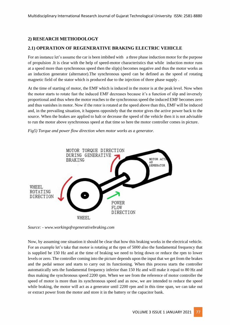
Fig5) Torque and power flow direction when motor works as a generator.
Source: - www.workingofregenerativebraking.com
Now, by assuming one situation it should be clear that how this braking works in the electrical vehicle.
For an example let’s take that motor is rotating at the rpm of 5000 also the fundamental frequency that
is supplied be 150 Hz and at the time of braking we need to bring down or reduce the rpm to lower
levels or zero. The controller coming into the picture depends upon the input that we get from the brakes
and the pedal sensor and starts to carry out its functioning. When this process starts the controller
automatically sets the fundamental frequency inferior than 150 Hz and will make it equal to 80 Hz and
thus making the synchronous speed 2200 rpm. When we see from the reference of motor controller the
speed of motor is more than its synchronous speed and as now, we are intended to reduce the speed
while braking, the motor will act as a generator until 2200 rpm and in this time span, we can take out
or extract power from the motor and store it in the battery or the capacitor bank.
Multidisciplinary International Research Journal of Gujarat Technological University ISSN: 2581-8880
VOLUME 3 ISSUE 1 JANUARY 2021 78
It is here noteworthy point that the battery continues to supply the power to the three phase induction
motors during the process of regenerative braking and this is because the magnetic flux of induction
motor is zero when the power given(source) is 0(OFF). Also, it is known that motor enacting as
generator draws the power which is reactive to produce the linkages of flux and gives active power
back. The law is different for every different motor to recover or regain the kinetic energy. For instance,
1) Permanent magnet motors can act as a generator even in the absence of source power because
permanent magnets are present in the rotor to generate magnetic flux.
2) Other similar types like DC shunt motor and others have residual magnetism in it which waives the
need of external excitation required to produce or generate flux which is magnetic in nature.
In majority of vehicles that are running on the electrical principal, the motor is joined to the singular
drive axle (mostly to the rear-wheel drive axle) and thus its necessary to use a mechanical braking or
the hydraulic braking for the front wheels. And this arises the necessity that the controller should
maintain coordination between both mechanical braking and the electronic braking system when we
apply brakes.
3) ANALYSIS AND OBSERVATION
3.1) OPERATION OF MOTOR IN ELECTRIC VEHICLES
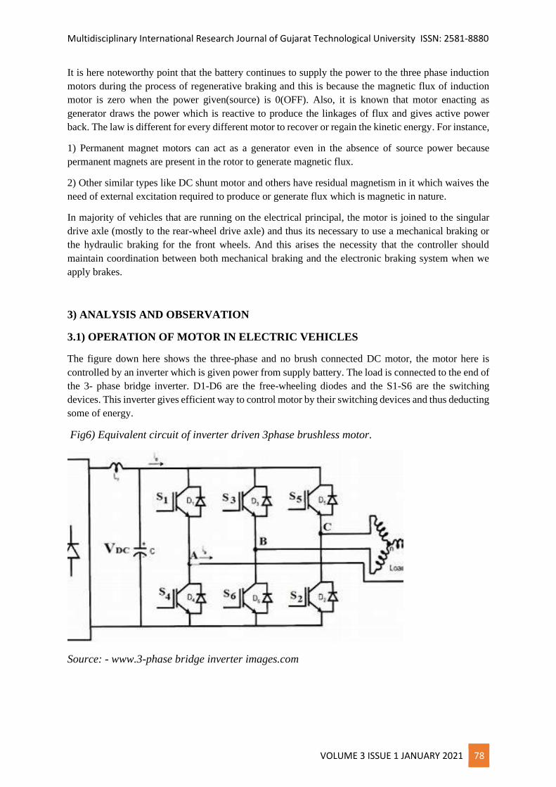
The figure down here shows the three-phase and no brush connected DC motor, the motor here is
controlled by an inverter which is given power from supply battery. The load is connected to the end of
the 3- phase bridge inverter. D1-D6 are the free-wheeling diodes and the S1-S6 are the switching
devices. This inverter gives efficient way to control motor by their switching devices and thus deducting
some of energy.
Fig6) Equivalent circuit of inverter driven 3phase brushless motor.
Source: - www.3-phase bridge inverter images.com
Multidisciplinary International Research Journal of Gujarat Technological University ISSN: 2581-8880
VOLUME 3 ISSUE 1 JANUARY 2021 79
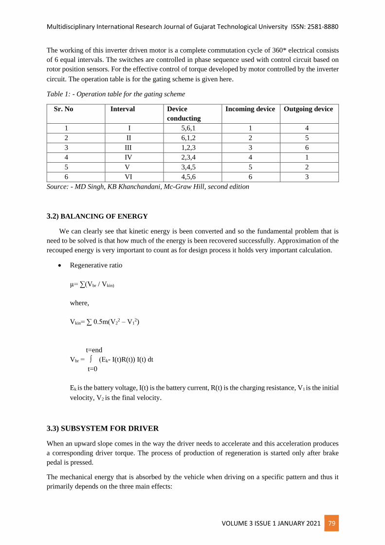
The working of this inverter driven motor is a complete commutation cycle of 360* electrical consists
of 6 equal intervals. The switches are controlled in phase sequence used with control circuit based on
rotor position sensors. For the effective control of torque developed by motor controlled by the inverter
circuit. The operation table is for the gating scheme is given here.
Table 1: - Operation table for the gating scheme
Sr. No Interval Device
conducting
Incoming device Outgoing device
1 I 5,6,1 1 4
2 II 6,1,2 2 5
3 III 1,2,3 3 6
4 IV 2,3,4 4 1
5 V 3,4,5 5 2
6 VI 4,5,6 6 3
Source: - MD Singh, KB Khanchandani, Mc-Graw Hill, second edition
3.2) BALANCING OF ENERGY
We can clearly see that kinetic energy is been converted and so the fundamental problem that is
need to be solved is that how much of the energy is been recovered successfully. Approximation of the
recouped energy is very important to count as for design process it holds very important calculation.
• Regenerative ratio
µ= ∑(Vbr / Vkin)
where,
Vkin= ∑ 0.5m(V22 – V1
2)
t=end
Vbr = ∫ (Ek- I(t)R(t)) I(t) dt
t=0
Ek is the battery voltage, I(t) is the battery current, R(t) is the charging resistance, V1 is the initial
velocity, V2 is the final velocity.
3.3) SUBSYSTEM FOR DRIVER
When an upward slope comes in the way the driver needs to accelerate and this acceleration produces
a corresponding driver torque. The process of production of regeneration is started only after brake
pedal is pressed.
The mechanical energy that is absorbed by the vehicle when driving on a specific pattern and thus it
primarily depends on the three main effects:
Multidisciplinary International Research Journal of Gujarat Technological University ISSN: 2581-8880
VOLUME 3 ISSUE 1 JANUARY 2021 80
1) aerodynamic friction loss
2) rolling friction loss
3) energy dissipated in the brakes
Mv dv(t)/dt = Ft(t)- (Fa(t)+ Fr(t) +Fg(t))
This equation shows the longitudinal dynamics of the road vehicle.
4) THE SIGNIFICANCE OF CAPACITOR BANK OR ULTRA CAPACITORS
During the action of braking there’s a sudden jerk and the speed reduces very quickly; we need to stop
or reduce speed immediately. Therefore, the braking system is of very short duration, batteries have
limitations and shortcomings so we cannot inject a huge amount of energy in the battery because it can
cause damage to battery or severe problems can be occurred at the time of braking and it can be a risk
and so to avoid this type of disadvantage, we need a capacitor bank or ultra-capacitors to the
regenerative braking system. This capacitor can discharge or charge for many cycles without any harm
or inefficient way, thus making capacitor bank is a prominent part of the system.
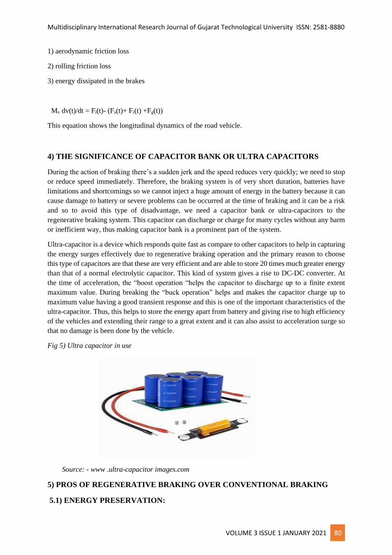
Ultra-capacitor is a device which responds quite fast as compare to other capacitors to help in capturing
the energy surges effectively due to regenerative braking operation and the primary reason to choose
this type of capacitors are that these are very efficient and are able to store 20 times much greater energy
than that of a normal electrolytic capacitor. This kind of system gives a rise to DC-DC converter. At
the time of acceleration, the “boost operation “helps the capacitor to discharge up to a finite extent
maximum value. During breaking the “buck operation” helps and makes the capacitor charge up to
maximum value having a good transient response and this is one of the important characteristics of the
ultra-capacitor. Thus, this helps to store the energy apart from battery and giving rise to high efficiency
of the vehicles and extending their range to a great extent and it can also assist to acceleration surge so
that no damage is been done by the vehicle.
Fig 5) Ultra capacitor in use
Source: - www .ultra-capacitor images.com
5) PROS OF REGENERATIVE BRAKING OVER CONVENTIONAL BRAKING
5.1) ENERGY PRESERVATION:
Multidisciplinary International Research Journal of Gujarat Technological University ISSN: 2581-8880
VOLUME 3 ISSUE 1 JANUARY 2021 81
The function of flywheel is to imbibe when braking is done with the help of a clutch system slowing
down the car and making the car halt at the needed position. Now to accelerate another clutch system
is advocated which connects the flywheel to the drive, thus leading to the higher speed to car and
accelerating it. Energy is thus, conserved and is not wasted in the form of heat or some other dissipations
which normally happens in the mechanical braking system.
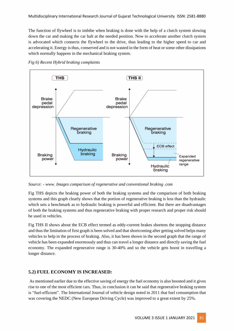
Fig 6) Recent Hybrid braking complaints
Source: - www. Images comparison of regenerative and conventional braking .com
Fig THS depicts the braking power of both the braking systems and the comparison of both braking
systems and this graph clearly shows that the portion of regenerative braking is less than the hydraulic
which sets a benchmark as to hydraulic braking is powerful and efficient. But there are disadvantages
of both the braking systems and thus regenerative braking with proper research and proper risk should
be used in vehicles.
Fig THS II shows about the ECB effect termed as eddy-current brakes shortens the stopping distance
and thus the limitation of first graph is been solved and that shortcoming after getting solved helps many
vehicles to help in the process of braking. Also, it has been shown in the second graph that the range of
vehicle has been expanded enormously and thus can travel a longer distance and directly saving the fuel
economy. The expanded regenerative range is 30-40% and so the vehicle gets boost in travelling a
longer distance.
5.2) FUEL ECONOMY IS INCREASED:
As mentioned earlier due to the effective saving of energy the fuel economy is also boosted and it gives
rise to one of the most efficient cars. Thus, in conclusion it can be said that regenerative braking system
is “fuel-efficient”. The International Journal of vehicle design noted in 2011 that fuel consumption that
was covering the NEDC (New European Driving Cycle) was improved to a great extent by 25%.
Multidisciplinary International Research Journal of Gujarat Technological University ISSN: 2581-8880
VOLUME 3 ISSUE 1 JANUARY 2021 82
Also, another example is depicted here. The Delhi metro saved or conserved up to 90,000 tons of (CO2)
from being liberated into atmosphere by regenerating 112,400 megawatts hour of electrical energy with
the proper use of regenerative braking system between 2004 – 2007. The most astonishing and mind-
boggling thing about regenerative braking is that it can capture the more than half wasted energy and
can put back to work in the vehicle and thus it has appreciable performance. The hydraulic braking
system is much better and efficient and can produce much more effective gains and lowering the use of
fuel by 30-45%.
5.3) WEAR OR TEAR AND FRICTION REDUCTION
In regenerative braking when the motor is getting or absorbing power from capacitor bank, it obstacles
the alignment of wheels, which takes energy of the motion and giving that energy again to the capacitor.
Thus, it reduces the wear and tear and so severe damage can be prevented and can make a smooth
working cycle of the car
6) IS IT RELEVANT TO ONLY EV’s (ELECTRICAL VEHICLES) OR ALL OTHER
VEHICLES?
This topic also needs to be analyzed because the small cars or the cars which are for the family purposes
can’t be imbibed with this system so by proper analysis, we can see that the cars which can have this
type of braking system should have proper alignment of vehicles, stored capacitor banks and it is present
only in the electrical vehicles. The family purpose vehicles are needed to have development to install
this type of braking system. The electrical vehicles are the most appropriate for having the regenerative
braking system.
There is no doubt regarding the retrieving potential/energy in the concept of regenerative braking
method. As stated earlier, the speed at which battery charges is much higher than at the rate at which
battery discharges and thus this gives rise to the small amount of energy that the battery can store during
the rapid slowing of the vehicle. And thus, the most important thing that comes into the picture is
that we should not use regenerative braking system under fully charged conditions. It is because
the overcharging can damage batteries due to severe heating of the equipment, but the electronic drive
circuit prevents the damage from overcharging. In this case the storage of energy is done in the capacitor
bank and it is given to the vehicle afterwards when needed and also it is used in extending the range.
The formula to find kinetic energy is 0.5*m*v2 and so the amount of kinetic energy that is retrieved
from the vehicle is proportional to the vehicle’s mass and the velocity at which the vehicle is going on.
The mass is much higher in vehicles like car, trucks, JCB’s, rollers and so they have more kinetic energy
retrieved. In the city areas these heavy vehicles would gain a large momentum after acceleration though
it has low starting speed, so during the decelerating, the kinetic energy is higher in electronic scooter
which is travelling at the same speed. Thus, the efficiency of regenerative braking is much higher in
electric cars, buses and vehicles. So, at last in conclusion it is to be said that this system is efficient for
vehicles having high mass.
7) TYPES OF SYSTEM FOR STORING ENERGY
The storage capacity is more advanced in the new technologies mainly concentrated around ultra-
capacitor, battery and converter needs to be joined to the vehicles of electric types. Various types of
batteries such as nickel-zinc, lead-acid. A basic comparative study is shown of batteries.
Multidisciplinary International Research Journal of Gujarat Technological University ISSN: 2581-8880
VOLUME 3 ISSUE 1 JANUARY 2021 83
Fig6) Life cycle, operating temp of different types of batteries
Battery type Energy density No. of cycles Operating range Temp.
Ion -Li 110-160 500-1000 200-600
Ni-Zn 60-85 1000 200-600
Lead acid battery 110-160 400-1200 200-600
Ni-Cd 45-80 2000 400-600
Source: - Wikipedia.org
Thus, we can observe that there are various types of battery available to store energy and can also be
used in the place of capacitor. Thus, batteries are the most basic and important element in the
regenerative braking system and can be considered a necessity to the system.
The battery should be connected properly in series with the system so that it can work or function
properly. Although there are many ways to connect battery in the vehicle. To choose proper battery and
the proper place to install the battery is also one of the challenging tasks that needs to be performed by
the engineers.
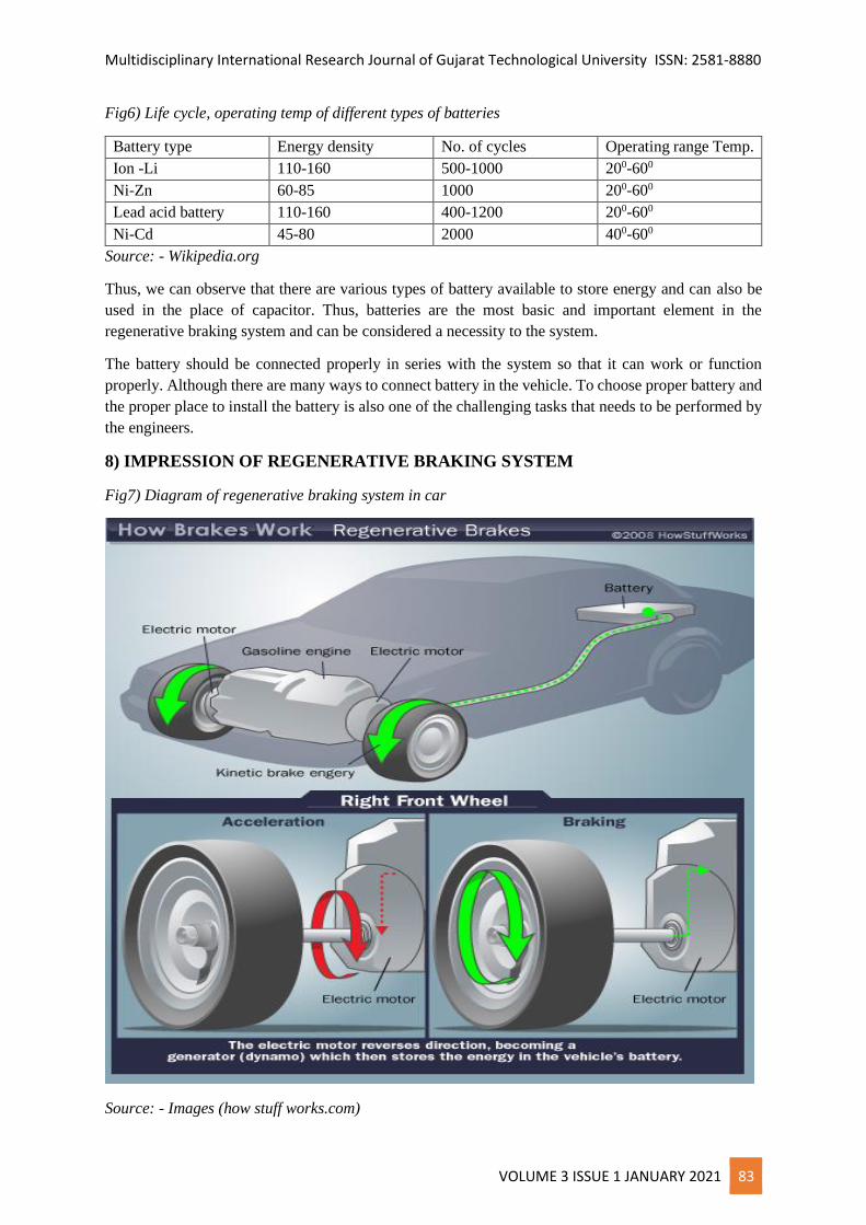
8) IMPRESSION OF REGENERATIVE BRAKING SYSTEM
Fig7) Diagram of regenerative braking system in car
Source: - Images (how stuff works.com)
Multidisciplinary International Research Journal of Gujarat Technological University ISSN: 2581-8880
VOLUME 3 ISSUE 1 JANUARY 2021 84
This simple diagram shows that how the regenerative braking system is able to retrieve some of the
vehicle’s kinetic energy and convert it to electricity or some other form of energy which can be used
when needed later.
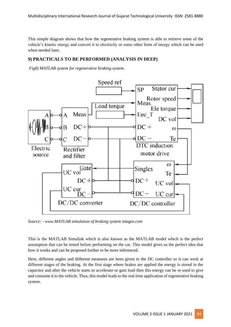
9) PRACTICALS TO BE PERFORMED (ANALYSIS IN DEEP)
Fig8) MATLAB system for regenerative braking system.
Source: - www.MATLAB simulation of braking system images.com
This is the MATLAB Simulink which is also known as the MATLAB model which is the perfect
assumption that can be tested before performing on the car. This model gives us the perfect idea that
how it works and can be proposed further to be more inferenced.
Here, different angles and different measures are been given to the DC controller so it can work at
different stages of the braking. At the first stage where brakes are applied the energy is stored in the
capacitor and after the vehicle starts to accelerate or gain load then this energy can be re-used to give
and consume it to the vehicle. Thus, this model leads to the real time application of regenerative braking
system.
Multidisciplinary International Research Journal of Gujarat Technological University ISSN: 2581-8880
VOLUME 3 ISSUE 1 JANUARY 2021 85
This MATLAB model as a result generates acceleration and braking at different cases and thus can be
made to be a precise consideration to install it in electrical vehicles and can be further initiated to large
vehicles like car, buses and trucks.
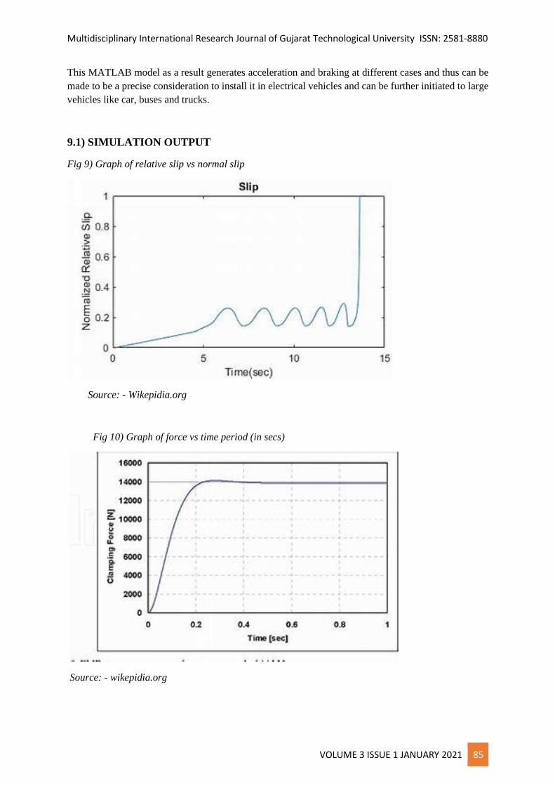
9.1) SIMULATION OUTPUT
Fig 9) Graph of relative slip vs normal slip
Source: - Wikepidia.org
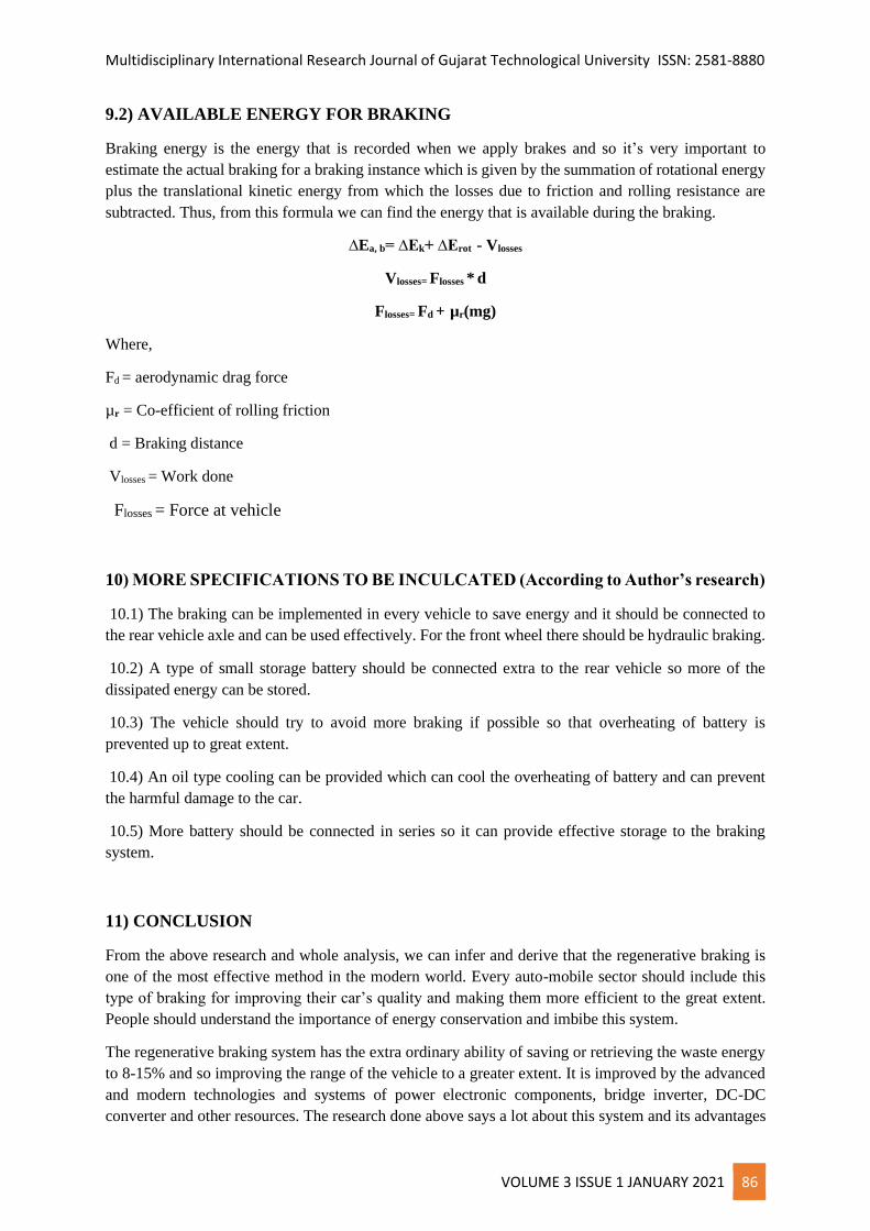
Fig 10) Graph of force vs time period (in secs)
Source: - wikepidia.org
Multidisciplinary International Research Journal of Gujarat Technological University ISSN: 2581-8880
VOLUME 3 ISSUE 1 JANUARY 2021 86
9.2) AVAILABLE ENERGY FOR BRAKING
Braking energy is the energy that is recorded when we apply brakes and so it’s very important to
estimate the actual braking for a braking instance which is given by the summation of rotational energy
plus the translational kinetic energy from which the losses due to friction and rolling resistance are
subtracted. Thus, from this formula we can find the energy that is available during the braking.
∆Ea, b= ∆Ek+ ∆Erot - Vlosses
Vlosses= Flosses * d
Flosses= Fd + µr(mg)
Where,
Fd = aerodynamic drag force
µr = Co-efficient of rolling friction
d = Braking distance
Vlosses = Work done
Flosses = Force at vehicle
10) MORE SPECIFICATIONS TO BE INCULCATED (According to Author’s research)
10.1) The braking can be implemented in every vehicle to save energy and it should be connected to
the rear vehicle axle and can be used effectively. For the front wheel there should be hydraulic braking.
10.2) A type of small storage battery should be connected extra to the rear vehicle so more of the
dissipated energy can be stored.
10.3) The vehicle should try to avoid more braking if possible so that overheating of battery is
prevented up to great extent.
10.4) An oil type cooling can be provided which can cool the overheating of battery and can prevent
the harmful damage to the car.
10.5) More battery should be connected in series so it can provide effective storage to the braking
system.
11) CONCLUSION
From the above research and whole analysis, we can infer and derive that the regenerative braking is
one of the most effective method in the modern world. Every auto-mobile sector should include this
type of braking for improving their car’s quality and making them more efficient to the great extent.
People should understand the importance of energy conservation and imbibe this system.
The regenerative braking system has the extra ordinary ability of saving or retrieving the waste energy
to 8-15% and so improving the range of the vehicle to a greater extent. It is improved by the advanced
and modern technologies and systems of power electronic components, bridge inverter, DC-DC
converter and other resources. The research done above says a lot about this system and its advantages
Multidisciplinary International Research Journal of Gujarat Technological University ISSN: 2581-8880
VOLUME 3 ISSUE 1 JANUARY 2021 87
to the world and auto-mobile industry. Also due to the sky touching petrol prices this system enables a
highly efficient fuel economy and makes a vehicle better than the conventional method. The friction
losses and other damages are also fully prevented and improves the fuel consumption by 33%.
The results derived above says that the power and energy is important and very useful and thus we need
to use the regenerative braking system in electric vehicles.
12) REFERENCES
1) Sri Hari Karthik. “How regenerative braking works in Electric Vehicles”. July 25, 2019
2) https:/HowRegenerativeBrakingWorks in Electric vehicles.html
3) Soniya.K. Malode. “Regenerative braking system in vehicles”. March 2016. IRJET (Vol 3 issue
3)
4) https://www.irjet.net/archives/V3/i3/IRJET-V3I381.pdf p-ISSN:2395-0072
5) R.H. Adware. “Regenerative braking system in vehicles”. March 2016. IRJET (Vol 3 issue 3)
6) https://www.irjet.net/archives/V3/i3/IRJET-V3I381.pdf p-ISSN:2395-0072
7) Harish Kumar “Regenerative Braking”. Seminar report. June 2017
8) reference0rp/52091807-Regenerative-braking.pdf
9) Wikipedia.org
10) Amrit Mahapatra, “Regenerative Braking in Induction Motor Drives in Applications to Electric
Vehicles” 2014 IEEE Students’ Conference on Electrical, Electronics and Computer Science,
2014.
11) www.Howstuffworks.com
12) www.images MATLAB simulation of regenerative braking system .com
13) www. Images Comparison of regenerative braking system.com
14) www.ultra-capacitor images.com
15) www.3-phase bridge inverter images.com
16) www.workingofregenerativebraking.com
17) J Wang, Binggang Cao, “Regeneratic Strategy for Electric Vehicles” IEEE, 2009.


![[PPT]Regenerative Braking Systems and their functions · Web viewHow Does Regenerative Braking Work? Regular brakes waste large amounts of useable energy6 Regenerative Braking systems](https://img.pdfslide.us/doc/110x75/5ae8634b7f8b9aee078f7805/pptregenerative-braking-systems-and-their-functions-viewhow-does-regenerative.jpg)
![REGENERATIVE BRAKING SYSTEM IN ELECTRIC VEHICLES · REGENERATIVE BRAKING SYSTEM IN ELECTRIC VEHICLES ... REGENERATIVE BRAKING SYSTEM ... Regenerative action during braking[9]](https://img.pdfslide.us/doc/110x75/5adccef67f8b9a1a088c7cf0/regenerative-braking-system-in-electric-vehicles-braking-system-in-electric-vehicles.jpg)