Embed Size (px)
Citation preview
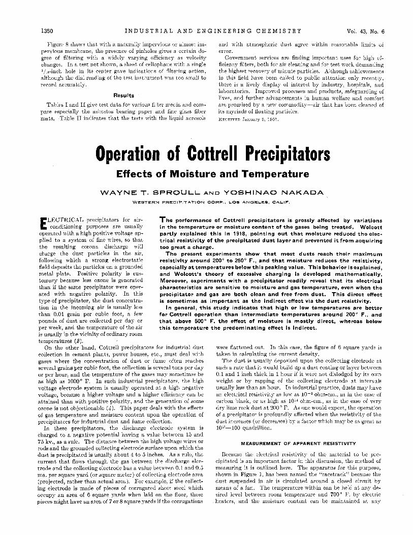
1350 I N D U S T R I A L A N D E N G I N E E R I N G C H E M I S T R Y Vol. 43, No. 6
Figure 8 shows t,hat' Lyith a naturally impervious or almost im- pervious membrane, the presence of pinholes gives a certain de- gree of filtering wit,h a widely varying efficiency as velocity changes. In a test not shown, a sheet, of cellophane viith a single I/ls-inch hole in its center gave indications of fikering action, although the dial reading of the test instrument n-as too small to record accurately.
Results
Tables I and I1 give test data for various filter media and com- pare especially the asbestos bearing paper and fine glass fiber mats. ,Table I1 indicates that the t,ests with the liquid aerosols
and with atmospheric dust agree within reasonable limits of error.
Government services are finding important uses for high ef- ficiency filters, both for air cleaning and for test work demanding the highest recovery of minute particles. Although achievements in this field have been called to public attention only recently, there is a lively display of interest by industry, hospitals, and laboratories. Improved processes and products, safeguarding of lives, and further advancements in human welfare and comfort are promised by a new commodity-air that has been cleaned of its myriads of floating particles. RECEIVED January 3, 1951.
Operation of C Effects of Moisture and
Precipitators Temperature
WAYNE T. S P R O U L L AND YOSHINAO NAKADA WESTERN PRECIPITATION GORP.. LOS ANGELES, CALIF,
LECTRICAL precipitators for air- E conditioning purposes are usually operated with a high positive voltage ap- plied to a system of fine wires, so that the resulting corona discharge will charge the dust particles in the air, following which a strong electrostatic field deposits the particles on a grounded metal plate. Positive polarity is cus- tomary because less ozone is generated than if the same precipitator were oper- ated with negative polarity. In this type of precipitator, the dust concentra- tion in the incoming air is usually less than 0.01 grain per cubic foot, a few pounds of dust are collected per day or per week, and the temperature of the air
T h e performance of Cottrell precipitators is grossly affected by variations in the temperature or moisture content of t h e gases being treated. Wolcott partly explained this i n 1918, pointing out t h a t moisture reduced the elec- trical resistivity of t h e precipitated dust layer and prevented i t from acquiring too great a charge.
The present experiments show t h a t most dusts reach their maximum resistivity around 200" t o 250" F., and t h a t moisture reduces the resistivity, especially attemperatures below this peaking value. This behavior isexplained, and Wolcott's theory of excessive charging i s developed mathematically. Moreover, experiments with a precipitator readily reveal t h a t its electrical characteristics are sensitive t o moisture and gas temperature, even when the precipitator and gas are both clean and free from dust. This direct effect i s sometimes as important as the indirect effect via the dust resistivity.
I n general, this study indicates t h a t high or low temperatures are better for Cottrell operation than intermediate temperatures around 200" F., and t h a t above 500" F. t h e effect of moisture is mostly direct, whereas below this temperature the predominating effect i s indirect.
is usually in the vicinity of ordinary room temperatures (2).
On the other hand, Cottrell precipitators foi industiial dust collection in cement plants, power houses, etc., must deal with gases where the concentration of dust or fume often reaches several grains per cubic foot, the collection is several tons per day or per hour, and the temperature of the gases may sometimes be as high as 1000" F. In such industrial precipitators, the high voltage electrode system is usually operated at a high negative voltage, because a higher voltage and a higher efficiency can be attained than with poPitive polarity, and the generation of some ozone is not objectionable (4) . This paper deals with the effects of gas temperature and moisture content upon the operation of precipitators for industrial dust and fume collection.
In these precipitators, the discharge electrode system is charged to a negative potential having a value between 15 and 75 kv., as a rule. The distance between the high voltage wires or rods and the grounded collecting electrode surface upon which the dust is precipitated is usually about 4 to 5 inches. As a rule, the current that flows through the gas between the discharge elec- trode and the collecting electrode has a value between 0.1 and 0.5 ma. per square yard (or square meter) of collecting electrode area (projected, rather than actual area). For example, if the collect- ing electrode is made of pieces of corrugated sheet steel which occupy an area of 6 square yards when laid on the floor, these pieces might have an area of 7 or 8 equare yards if the corrugations
were flattened out. In this case, the figure of 6 square yards is taken in calculating the current density.
The dust is usually deposited upon the collecting electrode at such a rate that it would build up a dust coating or layer between 0.1 and 1 inch thick in 1 hour if i t were not dislodged by its own weight or by rapping of the collecting electrode a t intervals usually less than an hour. In industrial practice, dusts may have an electrical resistivity as low as 10-3 ohm-cm., as in the case of carbon black, or as high as l O I 4 ohm-cm., as in the case of very dry lime rock dust a t 200 O F. As one would expect, the operation of a precipitator is profoundly affected when the resistivity of the dust increases (or decreases) by a factor which may be as great as lO"--lOO quadrillion.
MEASUREMENT OF APPARENT RESISTIVITY
Because the electrical resistivity of the material to be pre- cipitated is an important factor in this discussion, the method of measuring it is outlined here. The apparatus for this purpose, shown in Figure 1, has been named the "racetrack" because the duet suspended in air is circulated around a closed circuit by means of a fan. The temperature within can be held a t any dc- sired level between room temperature and 700" F. by electric heaters, and the moisture content can be maintained at any
June 1951 I N D U S T R I A L A N D E N G I N E E R I N G C H E M I S T R Y 1351
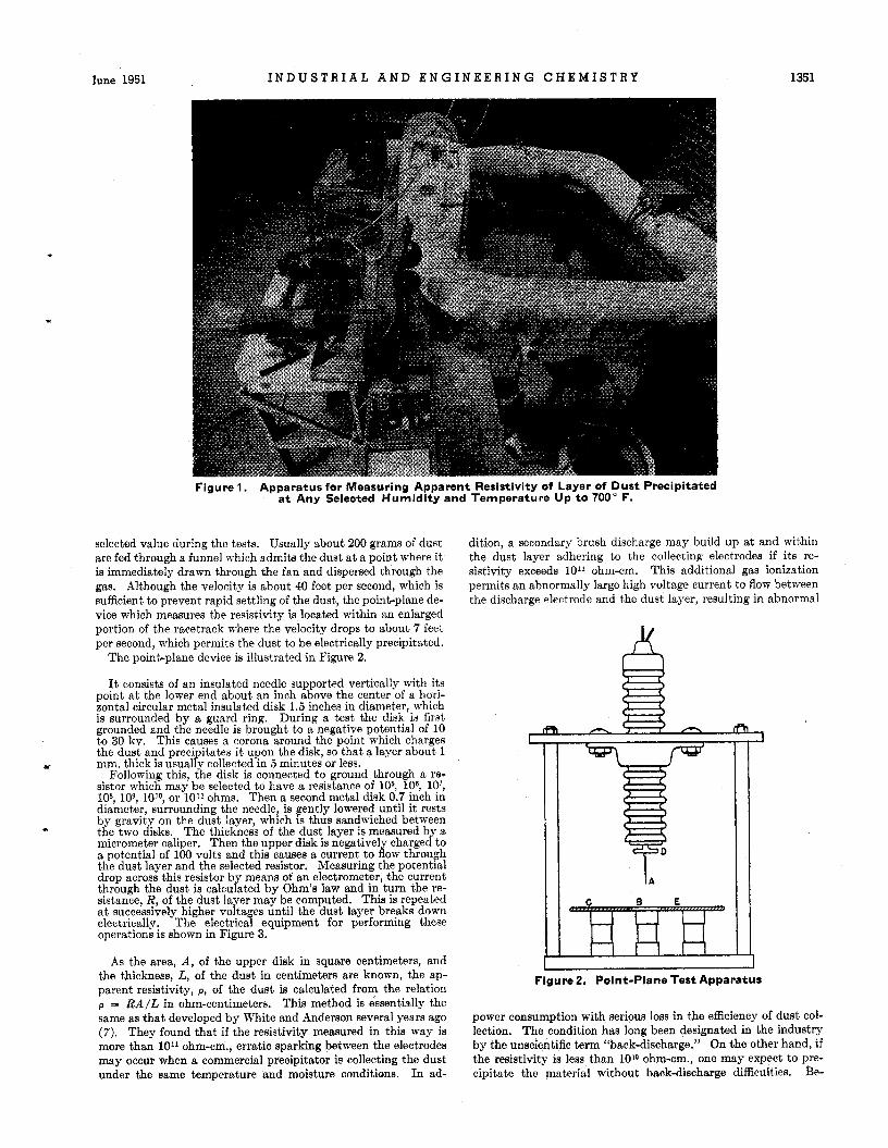
Figure 1. Apparatus for Measuring Apparent Resistivity of Layer of Dust Precipitated a t Any Selected Humidity and Temperature Up t o 700" F.
selected value during the tests. Usually about 200 grams of dust are fed through a funnel which admits the dust a t a point where it is immediately drawn through the fan and dispersed through the gas. Although the velocity is about 40 feet per second, which is sufficient to prevent rapid settling of the dust, the point-plane de- vice which measures the resistivity is located within an enlarged portion of the racetrack where the velocity drops to about 7 feet per second, which permits the dust to be electrically precipitated.
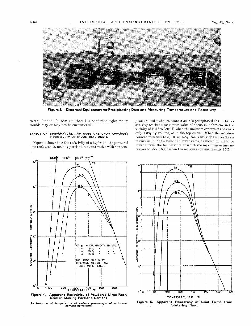
The point-plane device is illustrated in Figure 2.
It consists of an insulated needle supported vertically with its point a t the lower end about an inch above the center of a hori- zontal circular metal insulated disk 1.5 inches in diameter, which is surrounded by a guard ring. During a test the disk is first grounded and the needle is brought to a negative potential of 10 to 30 kv. This causes a corona around the point which charges the dust and precipitates it upon the disk, so that a layer about 1 mm. thick is usually collected in 5 minutes or less.
Following this, the disk is connected to ground through a re- sistor which may be selected to have a resistance of 106, 106, lq?, lo8, lo9, 1O1O, or 1011 ohms. Then a second metal disk 0.7 inch in diameter, surrounding the needle, is gently lowered until it rests by gravity on the dust layer, which is thus sandwiched between the two disks. micrometer caliper. Then the upper disk is negatively charged to a potential of 100 volts and this causes a current to flow through the dust layer and the selected resistor. Measuring the potential drop across this resistor by means of an electrometer, the current through the dust is calculated by Ohm's law and in turn the re- sistance, R, of the dust layer may be computed. This is repeated a t successively higher voltages until the dust layer breaks down electrically. The electrical equipment for performing these operations is shown in Figure 3.
*c
* The thickness of the dust layer is measured by a
As the area, A , of the upper disk in square centimeters, and the thickness, L, of the dust in centimeters are known, the ap- parent resistivity, p, of the dust is calculated from the relation p = R A / L in ohm-centimeters. This method is essentially the same as that developed by White and Anderson several years ago (7). They found that if the resistivity measured in this way is more than 101' ohm-cm., erratic sparking between the electrodes may occur when a commercial precipitator is collecting the dust under the same temperature and moisture conditions. In ad-
dition, a secondary brush discharge may build up a t and within the dust layer adhering to the collecting electrodes if its re- sistivity exceeds 1011 ohm-em, This additional gas ionization permits an abnormally large high voltage current to flow between the discharge electrode and the dust layer, resulting in abnormal
L
iT L I
Figure2. Point-Plane Test Apparatus
power consumption with serious loss in the efficiency of dust col- lection. The condition has long been designated in the industry by the unscientific term "back-discharge." On the other hand, if the resistivity is less than 1010 ohm-cm., one may expect to pre- cipitate the material without back-discharge difficulties. Be-
1352 I N D U S T R I A L A N D E N G I N E E R I N G C H E M I S T R Y Vol. 43, No. 6
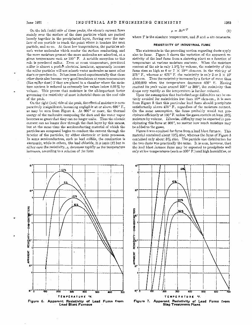
Figure 3. Electrical Equipment for Precipitating Dust and Measuring Temperature and Resistivity
tween 1010 and 1011 ohm-cm. there is a borderline region where trouble may or may not be encountered.
EFFECT OF TEMPERATURE AND MOISTURE UPON APPARENT RESISTIVITY O F INDUSTRIAL DUSTS
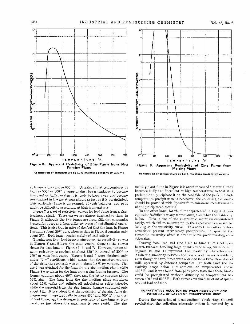
Figure 4 shows how the resistivity of a typical dust (powdered lime rock used in making portland cement) varies Yith the tem-
perature and moisture content as it is precipitated (5) . The re- sistivity reaches a maximum value of about 1014 ohm-cm. in the vicinity of 200' to 250" F. when the moisture content of the gas is only 1.3% by volume, as in the top curve. When the moisture content increases to 5 , 10, or l5%, the resistivity still reaches a maximum, but a t a lower and IoiTer value, as shown by the three lower curves, the temperature a t which the maximum occurs in- creases to about 330" when the moisture content reaches 15%.
loc
loQ
a' a
r W
L Io"
k 8 f I
0
tay - f
z Io9
W a
c z W a
me
AT x - 13% HUMIDITY BY ML. 0 5 % u
n 15% 'I
A 10 % ' I "
OR TUBE MILL DUST
CRESTMORE CALIF.
300 500 ,600 TEYPERATUGO *F.
Figure 4. Apparent Resistivity of Powdered Lime Rock Used in Making Portland Cement
As function of temperature a t various percentages of molsture content by volume
TEMPERAT IJ R E OF.
Figure 5. Apparent Resistivity of Lead Fume from Sintering Plant
June 1951 I N D U S T R I A L A N D E N G I N E E R I N G C H E M I S T R Y 1353
On the left (cold) side of these peaks, the electric current flows mainly over the surface of the dust particles which are packed loosely together in the precipitated layer, flowing over the sur- face of one particle to reach the point where it touches the next particle, and so on. At these low temperatures, the particles ad- sorb water molecules which render the surface conducting, and the more moisture present the more molecules are adsorbed, a t a given temperature such as 150" F. A notable exception to this rule is powdered sulfur. Even at room temperature, powdered sulfur is almost a perfeh electrical insulator, apparently because the sulfur particles will not adsorb water moJecules as most other dusts or powders do. It has been found experimentally that these other dusts also become very good insulators a t room temperature (like sulfur dust) if they are placed in a chamber where the mois- ture content is reduced to extremely low values below 0.01% by volume. This proves that moisture is the all-important factor governing the resistivity of most industrial dusts on the cool side of the peak.
On the right (hot) side of the peak, the effect of moisture is com- paratively insignificant, becoming negligible a t or above 600' F., as may be seen from Figure 4. At 600" or more, the thermal energy of the molecules composing the dust and the water vapor becomes so great that they can no longer unite. Thus the electric current can no longer flow through the dust layer by this means, but a t the same time the semiconducting material of which the particles are composed begins to conduct the current through the interior of the particles, by either electronic or ionic processes. In some semiconductors, such as lead sulfide, the conduction is electronic, while in others, like lead chloride, it is ionic (6) but in either case the resistivity, p , decreases rapidly as the temperature increases, according to a relation of the form
*
where T is the absolute temperature, and B and CY are constants.
RESISTIVITY OF INDUSTRIAL FUME
The statements in the preceding section regarding dusts apply also to fume. Figure 5 shows the variation of the apparent re- sistivity of the lead fume from a sintering plant as a function of temperature a t various moisture contents. When the moisture content of the air is only 1.3% by volume, the resistivity of this fume rises as high as 6 or 7 X 10'3 ohm-cm. in the vicinity of 275" F., whereas a t 675" F. the resistivity is only 2 or 3 x 10⁷ ohm-cm. Thus the resistivity increases by a factor of more than 1,000,000 when the temperature decreases 400" F. Having reached its peak value around 250 ' or 300 O, the resistivity then drops very rapidly as the temperature is further reduced.
Upon the assumption that back-discharge difficulties can be en- tirely avoided for resistivities less than 1010 ohm-em., it is seen from Figure 5 that this particular lead fume should precipitate satisfactorily above 475" F., regardless of the moisture content. On the same assumption, the fume probably would not pre- cipitate efficiently a t 150 O F. unless the gases contain a t least 10% moisture by volume. Likewise, difficulty may be expected in pre- cipitating this fume a t 300°, no matter how much moisture may be added to the gaaes.
Figure 6 was obtained for fume from a lead blast furnace. This material contained about 13% zinc, whereas the fume of Figure 5 contained only about 3% zinc. The particle size distribution for the two dusts was practically the same. It is seen, however, that the lead blast furnace fume may be expected to precipitate well only a t low temperatures (such as 100" F.) and high humidities, or
T E M P E R A T U R E OF.
Figure 6. Apparent Resistivity of Lead Fume from Lead Blast Furnace
T E M P E R A T U R E OF.
Figure 7. Apparent Resistivity of Lead Fume from Slag Treatment Plant
1354 I N D U S T R I A L A N D E N G I N E E R I N G C H E M I S T R Y Vol. 43, No. 6
T E M P E R A T U R E O F .
Figure 8. Apparent Resistivity of Zinc Fume from Slag Fuming Plant
As function of temperature a t 1.3% moisture content by volume
at temperatures above 650" F. Occasionally a t temperatures as high as 500" or W", a fume or dust has a tendency to become flocculent or fluffy, so that it is likely to blow away and become re-entrained in the gas stream almost as fast as it is precipitated. This particular fume is an example of such behavior, and eo it might be difficult to precipitate a t high temperatures.
Figure 7 is a set of resistivity curves for lead fume from a slag- treatment plant. These curves are almost identical to those in Figure 5, although the two fumes are from different companies located far apart and from different types of metallurgical opera- tions. This is also true in spite of the fact that the fume in Figure 7 contains about 20y0 zinc, whereas that in Figure 5 contains only about 3%. Both fumes consist mainly of lead sulfate.
Turning now from lead fume to zinc fume, the resistivity curves in Figures 8 and 9 have the same general shape as the curves shown for lead fume in Figures 5, 6, and 7. However, the maxi- mum resistivity is reached at about 130" F. instead of 200" or 250" as with lead fume. Figures 8 and 9 were obtained only under "dry" conditions, Jvhich means that the moisture content of the air in the racetrack was only about 1.3% by volume. Fig- ure 9 was obtained for the fume from a zinc melting plant, \vhile Figure 8 was taken for the fume from a slag fuming furnace. The former contains about 4070 zinc, and the latter contains about 50% zinc. The fume from the zinc melting plant contained about 15% sulfur and sulfate, all calculated ae sulfur trioxide, while the material from the slag fuming furnace contained only about 1%. It is evident that the resistivity of the zinc fume de- creases much more gradually between 400' and 700' F. than that of lead fume, but the decrease in resistivity of zinc fume a t tem- peratures just above the maximum is very rapid. The zinc
I
Y
2 W QK
!
v t Y E
t ZK !! ri
5
k a
K
W K 4
K
IC
T E M P E R A T U R E O F .
Figure 9. Apparent Resistivity of Zinc Fume from Melting Plant
As function of temperature a t 1.3% moisture content by volume
melting plant fume in Figure 9 is another case of a material that becomes fluffy and flocculent at high temperatures, so that it is preferable to precipitate it on the cool side of the peak; if high temperature precipitation is necessary, the collecting electrodes should be provided with "pockets" to minimize re-entrainment of the precipitated material.
On the other hand, for the fume represented in Figure 8, pre- cipitation is difficult a t any temperature, even when the resistivity is low. This is one of the exceptional materials encountered rarely, which fail to measure up to the expectations aroused by looking a t the resistivity curve. This shows that other factors sometimes prevent satisfactory precipitation, in spite of the favorable resistivity which is ordinarily the predominating con- sideration,
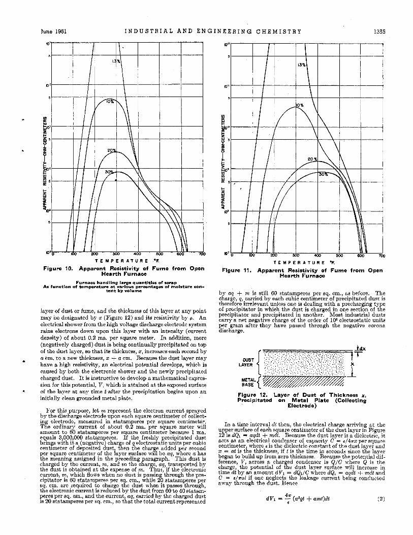
Turning from lead and zinc fume to fume from steel open hearth furnaces handling large quantities of scrap, the curves in Figures 10 and 11 represent the resistivity characteristics. Again the similarity between the two sets of curves is evident, even though the two fumes were obtained from two different steel mills operated by different companies. In both cases the re- sistivity drops below 1O1o ohm-em. a t temperatures above 400" F., and it was found from pilot plant tests that these fumes could be precipitated without difficulty a t temperatures be- tween 400' and 600' F. Both fumes contained substantial quan- tities of lead and zinc.
QUANTITATIVE RELATION BETWEEN RESISTIVITY AND POTENTIAL OF LAYER OF PRECIPITATED DUST
During the operation of a conventional single-stage Cottrell precipitator, the collecting electrode system is covered by a
lune 1951 I N D U S T R I A L A N D E N G I N E E R I N G C H E M I S T R Y 1355
5 I 1.3 %
0 ’ 2 I
T E M P E R A T U R E OF.
Figure 10. Apparent Resistivity of Fume from Open Hearth Furnace
Furnace handling large quantities of scrap As function of temperature a t various percentages of molsture con-
tent by volume
layer of dust or fume, and the thickness of this layer a t any point may be designated by x (Figure 12) and its resistivity by p. An electrical shower from the high voltage discharge electrode system rains electrons down upon this layer with an intensity (current density) of about 0.2 ma. per square meter. In addition, more (negatively charged) dust is being continually precipitated on top of the dust layer, so that its thickness, 2, increases each second by a em. to a new thickness, z + a em. Because the dust layer may have a high resistivity, an electrical potential develops, which is caused by both the electronic shower and the newly precipitated charged dust. It is instructive to develop a mathematical expres- sion for this potential, V , which is attained a t the exposed surface of the layer a t any time t after the precipitation begins upon an initially clean grounded metal plate.
For this purpose, let m represent the electron current sprayed by the discharge electrode upon each square centimeter of collect- ing electrode, measured in statamperes per square centimeter, The ordinary current of about 0.2 ma. per square meter will amount to 60 statamperes per square centimeter because 1 ma. equals 3,000,000 statamperes. If the freshly precipitated dust brings with it a (negative) charge of q electrostatic units per cubic centimeter of deposited dust, then the charge added per second per square centimeter of the layer surface will be aq, where a has the meaning assigned in the preceding paragraph. This dust is charged by the current, m, and so the charge, aq, transported by the dust is obtained a t the expense of m. Thus, if the electronic current, m, which flows when no dust is passing through the pre- cipitator is 60 statamperes per sq. cm., while 20 statamperes per sq. cm. are required to charge the dust when it passes through, the electronic current is reduced by the dust from 60 to 40 statam- peres per sq. cm., and the current, aq, carried by the charged dust is 20 statamperes per sq. em., so that the total current represented
T E M P E R A T U R E OF.
Figure 11. Apparent Resistivity of Fume from Open Hearth Furnace
by aq + m is still 60 statamperes per sq. em., as before. The charge, q, carried by each cubic centimeter of precipitated dust is therefore irrelevant unless one is dealing with a precharging type of precipitator in which the dust is charged in one section of the precipitator and precipitated in another. Most industrial dusts carry a net negative charge of the order of 106 electrostatic units per gram after they have passed through the negative corona discharge.
Figure 12. Layer of Dust of Thickness x, Precipitated on Metal Plate (Collecting
Electrode)
In a time interval dt then, the electrical charge arriving a t the upper surface of each square centimeter of the dust layer in Figure 12 is dQ1 = a@.+ mdt. Because the dust layer is a dielectric, i t acts as an electrical condenser of capacity C = 4 4 ~ x per square centimeter, where E is the dielectric constant of the dust layer and 2 = at is the thickness, if t is the time in seconds since the layer began to build up from zero thickness. Because the potential dif- ference, V, across a charged condenser is Q / C where Q is the charge, the potential of the dust layer surface will increase in time dt by an amount dV1 = dQL/C where dQ1 = aqdt + mdt and C = € / r a t if one neglects the leakage current being conducted away through the dust. Hence
1356 I N D U S T R I A L A N D E N G I N E E R I N G C H E M I S T R Y Vol. 43, No. 6
Meanwhile, charge is leaking away to the collecting electrode a t a rate given by Ohm's law as V I R , where V is the potential difference between top and bottom of the layer and R is the re- sistance per square centimeter given by R = px = pat. Hence the charge leakage in time d t is dQ2 = (V/pat )dt . This reduces the potential difference, V , by an amount dVs given by
47rV dV:! = ~ d t P E
(3)
Then the net gain in potential d V in time dt is
47ra 47r dV = dV1 - dVz =)y (an + m)tdt - - Vdt (4) PE
47a 4T For brevity, set A = - (aq + m) and B = -
P E
Then dV = Atdt - BVdt (6)
Multiplying by the integrating factor, e B t , and integrating, one has
(7) A B2 V = - (Bt - 1) + ce-Bi
or from Equation 5,
When t = 0, V = 0, from which it follows that the integration con st ant
and so
The expression 4?rt/pe occurs in the exponent in the last term. In practice, p is rarely greater than 10 statohm-cm. (9 X 1 O I 2 ohm-em.) and E is rarely greater than 6, so that after 10 seconds ( t = 10) this last term is negligible in most of the practical cases. This permits Equation 10 to be reduced to a simpler approxima- tion:
Or if one notes that at = 2, the thickness of the dust layer, and if one represents the total current density aq + m by the letter +, then Equation 11 becomes
This approximation is valid only for values of t greater than about 10 seconds, and Equation 10 should be used for smaller values of 1. In deriving the above equations, c.g.8. electrostatic units have been used throughout. The final simplified approxi- mations, Equations 11 and 12, therefore require that p be ex- pressed in statohm-centimeters in expressions like ps/4d if t is to be in seconds. This is true because capacitances were calculated in statfarads or centimeters, whereas to use practical units the capacitance must be in farads, which are much larger; 1 farad equals 9 X 10¹¹ statfarads. If practical units are to be used, Equations 11 and 12 become
and
where Vis in volts, p is in ohm-em., a is in cm. per second, p is in coulombs per cubic centimeter, m and + are in amperes per square centimeter, t is in seconds, and E is dimensionless.
In Equation 14, which is valid for values of 1 greater than about 10 seconds, it is seen that the term pe/36 X 1 O 1 L d is small com- pared to 1 unless p has very high values, in excess of, say, 10'3 ohm-cm. For such extreme resistivities, the exponential term in
Equation IO should be used. In ordinary cases, however, Equa- tion 14 reduces essentially to
V = pz+ (15)
This simplified result represents the voltage across the dust layer when electrical equilibrium is attained. Under these con- ditions, the current leaking through the dust layer to the collect- ing electrode exactly balances the current arriving at the exposed surface of the dust layer due to the arrival of additional charged dust, combined with the electronic current from the discharge electrode. Thus the expression for the potential drop reduces essentially to Ohm's law.
The usual precipitator current density, of the order of 0.2 ma. per square meter, amounts to about 2 x lo-* ampere per square centimeter for +. Hence if p is as high as 1012 ohm-em., V reaches a value around 2 kv. when the precipitated layer attains a thick- ness of 1 mm., or about 0.04 inch. From this, it is apparent that precipitated dust layers as thick as 0.125 inch may readily be sub- jected to voltages of several kilovolts when the resistivity is high. In other words, the layer of precipitated dust begins to act like an electrical insulator of poor quality.
INDIRECT EFFECT OF MOISTURE UPON PRECIPITATOR PERFORMANCE V IA DUST RESISTIVITY
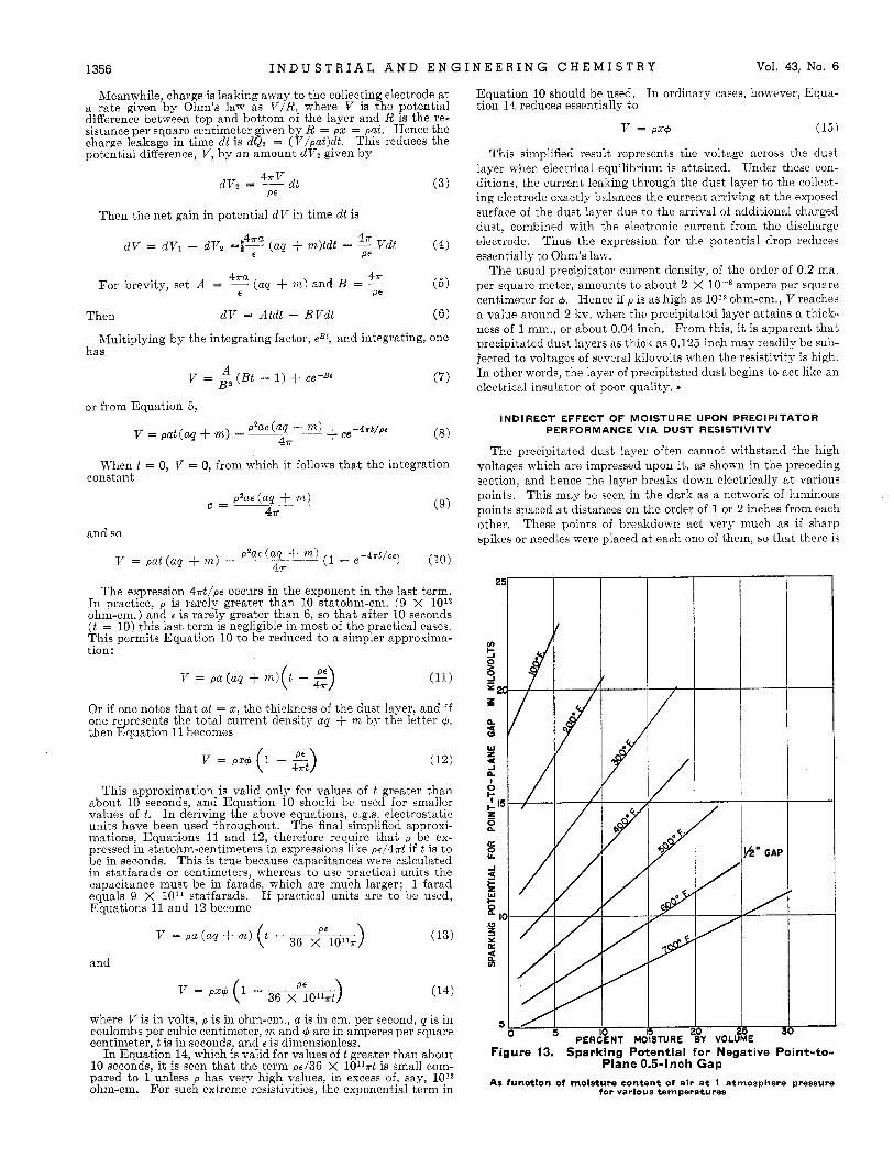
The precipitated dust layer often cannot withstand the high voltages which are impressed upon it, as shown in the preceding section, and hence the layer breaks down electrically a t various points. This may be seen in the dark as a network of luminous points spaced a t distances on the order of 1 or 2 inches from each other. These points of breakdown act very much as if sharp spikes or needles were placed a t each one of them, so that there is
Figure 13. Sparking Potential for Negative Point-to- Plane 0.5-Inch Gap
As Cunctlon of rnolsture content of air a t 1 atmosphere pressure for various temperatures
June 1951 I N D U S T R I A L A N D E N G I N E E R I N G C H E M I S T R Y 1357
frequent sparking between the discharge wire or rod and one or more of these points. Thus the voltage applied to the precipitator must be reduced to prevent excessive sparking.
Another consequence may be that a general glow discharge wilI occur fairly uniformly throughout the dust layer, so that the whole layer will glow like a fluorescent or phosphorescent powder in the dark. This means that ions, instead of being generated only at or near the discharge electrode, as in a clean precipitator are now generated a t both the discharge and the collecting elec- trodes. As a result, the current flowing between the two sets of electrodes increases, and the voltage which can be maintained de- creases. This phenomenon is usually called “back-discharge” by people who work with Cottrell precipitators.
Either excessive sparking or back-discharge as just defined will seriously impair the efficiency of operation of a precipitator. As
layer of precipitated dust may be minimized by reducing p, z, or 9. If 4 is reduced much below 0.2 ma. per square meter in a single- stage precipitator, the dust will not acquire sufficient charge to precipitate efficiently. Even in a two-stage precipitator, where 6 is reduced to merely aq (in Equation 13) instead of aq + m, the reduction in V would not be over perhaps 70%, because m is not large compared to aq when dust is being precipitated a t rates com- mon in industry. The thickness, 5, may be reduced by frequent rapping, but this increases the dust loss by re-entrainment in the gas stream. The other possibility is to reduce p. This can be done, in general, if the gas temperature is less than 600” F., by using water sprays or steam jets to increase the moisture content, which affects the resistivity as represented in Figure 4, for most dusts. If the dust does not readily adsorb moisture, it may be made more able to do so by “conditioning” with agents such as ammonia (for acidic dusts) or acid mist (for basic dusts). Another way to reduce the resistivity is to increase the temperature, if on
*
.I may be seen from Equation 15, the voltage building up across the
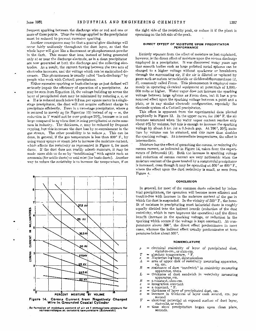
PERCENT MOISTURE BY VOLUME
Figure 14. Corona Current from Negatively Charged Wire in Grounded Coaxial Cylinder
.As function of moisture content of air a t 1 atmos here pressure for various voltages a t tonstant temperature (&wowski)
the right side of the resistivity peak, or reduce it if the plant is operating on the left side of the peak.
DIRECT EFFECT OF MOISTURE UPON PRECIPITATOR PERFORMANCE
Entirely separate from the effect of moisture as just explained, however, is the direct effect of moisture upon the corona discharge employed in a precipitator. It was discovered many years ago that smooth bodies such as large polished metal spheres can be charged to a higher voltage without sparkover or breakdown through the surrounding air, if the air is diluted or replaced by gases such as carbon tetrachloride or dichlorodifluoromethane (1 , S), commonly called Freon. This phenomenon is employed com- monly in operating electrical equipment at potentials of 1,000,- 000 volts or higher. Water vapor does not increase the sparking voltage between large spheres as Freon does, but it has a pro- nounced effect upon the sparking voltage between a point and a plate, or in any similar electrode configuration, especially the electrode system of a Cottrell precipitator.
This effect is apparent from the experimental data plotted graphically in Figure 13. In the upper curve, for 100 O F. the air becomes saturated when the water vapor content reaches only about 6% by volume, but this is enough to increase the sparking voltage by about 5 kv. for a 0.5-inch gap. At 700°, 30% mois- ture by volume can be attained, and this more than doubles the sparking voltage. At intermediate temperatures, the effect is intermediate.
Moisture has the effect of quenching the corona, or reducing the corona current, as indicated in Figure 14, taken from the experi- ments of Zebrowski (8). Both the increase in sparking voltage and reduction of corona current are very noticeable when the moisture content of the gases treated by a commercial precipitator is increased, even though it may be operating a t 500” or 600” F., where the effect upon the dust resistivity is small, as seen from Figure 4.
CONCLUSION
In general, for most of the common dusts collected by indus- trial precipitators, the operation will become more efficient and trouble-free with increase in the moisture content of the gas in which the dust is suspended. In the vicinity of 500 O F. , the bene- fit of moisture in precipitating most industrial dusts is roughly equally divided into the indirect benefit (reduction of the dust resistivity, which in turn improves the operation) and the direct benefit (increase in the sparking voltage, or reduction in the sparking which occurs if the voltage is kept constant). At tem- peratures above 500 O, the direct effect predominates in most cases, whereas the indirect effect usually predominates a t tem- peratures below about 500 ’.
NOMENCLATURE
p = electrical resistivity of layer of precipitated dust, statohm-cm., or ohm-cm.
T = absolute temperature, F. e = Napierian log base, dimensionless A = area of upper disk of resistivity measuring apparatus,
R = resistance of dust “sandwich” in resistivity measuring
L = thickness of dust sandwich in resistivity measuring
B = a constant, ohm-cm. c = integration tonstant 01 = a constant, F. z = thickness of layer of precipitated dust, cm. a = increase in thickness of layer each second, cm. per
V = electrical potential a t exposed surface of dust layer,
t = time since precipitation began upon clean plate,
sq. cm.
apparatus, ohms
apparatus, cm.
second
statvolts, or volts
seconds.
1358 I N D U S T R I A L A N D E N G I N E E R I N G C H E M I S T R Y Vol. 43, No. 6
m = electronic current density a t surface of dust layer, LITERATURE CITED statamperes per sq. em., or amperes per sq. cm.
statcoulombs per cc., or coulombs per cc.
statcoulombs per sq. em.
statcoulombs per sq. cm.
statcoulombs per sq. cm.
proaching charges, statvolts
leakage (conductivitx), statvolts
q = charge carried by each cc. of dust as it is precipitated,
Q = charge density upon exposed surface of dust layer,
d&l = increase in charge density due to approaching charges,
dQ2 = decrease in charge density due to leakage (conductivity)
d V l = increase in potential of dust layer surface due to ap-
dV2 = decrease in potential of dust layer surface due to
C = capacitance of dust layer per unit area, statfarads per
(1) Hudson, C. M., Hoisington, L. E., and Royt, L. E., P h y s . Rea., 52,
(2) McWhirter, C. H., and Posey, R. F., Elec. Eng., 68, 783 (Septem-
(3) Parkinson, D. B., Herb, R. G. , Bernet, E. J., and McKlbben,
(4) Schmidt, W. A, ISD. ENG. CHEX., 41, 2428 (1949). (5) Schmidt, W. A., Sproull, TT. T., and Xakada, Y., paper presented
(6) Seite, F., “Modern Theoiy of Solids,” pp. 56, 67, etc., New Yolk,
( i) White, 1%. J., and Anderson, E., unpublished laboratory repoi ts. (8) Zebrowski, S. P., Phys. Z., 33, 727 (1932).
664 (1937).
ber 1949).
J. L., Phvs. Rea., 53, 642 (1938).
a t A.I.M.M.E. Meeting, Kew York, Feb. 15, 1950.
McGraw-Hill Book Co., 1940.
sq. cm. RECEIVED January 3, 1951. Material presented in part at 170th General Meeting, American Institute of Mining and Metallurgical Engineers, New York, February 15, 1950 (61, and in part at the Symposium on Dispersions in Gases, Division of Indujtrial and Engineering Chemistry, AXTERIC.4X CHEMICAL SOCIETY, Baltimore, RId., December 29, 1950.
E
+ = dielectric constant of precipitated dust = total current density due to incidence Of electrons and
charged dust, statamperes per Sq. em. or amperes per sq. cm.
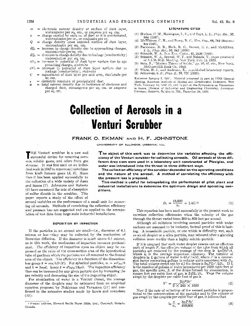
Collection of Aerosols in a Venturi Scrubber
FRANK 0. EKMAN’ AND H. F. JOHNSTONE UNIVERSITY OF ILLINOIS. URBANA, ILL.
HE Venturi scrubber a and T successful device for removing aero- Soluble gases, and Odors from gas
streams. I t was first used on an indus- trial scale in 1947 to remove salt cake fume from kraft furnace gases ($9 s). Since then it has been applied successfully to the collection of a wide variety of dusts and f ~ ~ m e s ( 7 ) . Johnstone and (6) have measured the rate of absorption of sulfur dioxide in the scrubber. This paper reports a study of the effect of several variables on the performance of a small unit for iemov-
and pressure loss are suggested and are applied to the cxtrapo- lation of test data from large scale industrial installations.
T h e object of this work was t o determine the variables affecting the effi- ciency of the Venturi scrubber foscollecting aerosols. Oil aerosols of three dif- ferent drop sizes were used in a laboratory unit constructed of Plexiglas, and water was introduced into the throat in three different ways.
Thecollection efficiency of the scrubber depended on the operating conditions and the nature of the aerosol. A method of correlating the efficiency with the pressure loss is proposed.
This method i s useful for extrapolating the performance of pilot plant and industrial installations t o determine the opt imum design and operating con- ditions.
Do = __ 16,000 + 1.4T,1.6 ( 1 )
This equation has been used successfully in the present work to correlate collection efficiencies when the velocity of the gas through the throat varied from 200 to 500 feet per second.
Although all collisions involving aerosol particles with water surfaces are assumed to be inelastic, factual proof of this is lack- ing. A nonsoluble particle, or one which is difficultly viet, such as an oil droplet or a silica particle, may rebound after a glancing collision more readily than a highly soluble particle.
If it is assumed that each water droplet sweeps out an effective path of length P , the effective volume of the tube from which all particles are removed by the passage of the drop is ?:?rD?P/4, where i t is the average impaction efficiency. The number of droplets in L gallons of water is 6Lc‘/rD,“, where c’ is a conver- sion factor converting gallons to volume units consistent with Do. The total volume swept out by all the drops is 3qtPLc‘/2D0. If L is the number of gallons of water introduced per 1000 cubic feet of gas, the specific area, 8, of the drops formed by atornization, in square feet per cubic foot of gas, is 245L/D0. Thus the volume swept by the droplets per cubic foot of gas is
(2) V’ =
tional to the concentration of the particles and to the volume of gas swept by the droplets per cubic foot of gas, it follows that
ing oil aerosols. Methods of correlating the collection efficiency u2
DEPOSITION BY IMPACTION
If the particles in an aerosol are smal]-i.e., diameter of 0.1 micron or less-they may be collected by the mechanism of Brownian diffusion. If the diameter is much above 0.1 micron, as in this work, the mechanism of impaction becomes predonii- nant. The efficiency of impaction Won an object may be ex- pressed as the ratio of the cross-section area of the hypothetical tube of gas from which the particles are all removed to the frontal area of the object, The efficiency is a function of the dimension- less group 0 = mu/kD (6 ) . For spherical Particles, m = “ d 3 P p / 6 and k = 3 r p d ; hence e = dapp,/18pD. The impaction efficiency thus can be increased for any given particle size by increasing the gas velocity and decreasing the size of the impacting object.
For atomization of water in a Venturi throat, thc average diameter of the droplets may be estimated from an empirical equation proposed by Nukiyama and Tanasawa (11) and con-
(10):
3i$PSc’ 2 X 245 X 1000
firmed in the extensive studies made by Lewis and coworkers Now if the rate of collection of the aerosol particles is propor-
1 Present address, Howard Smith Paper Mills, Ltd., Cornwall, Ontario, Canada.
x 3YrPSc’ In- ___ no 490,000 (3)