Embed Size (px)
DESCRIPTION
Operation Mnaual3 Samgong(Rev)
Citation preview

Operation Manual3SELFJECTOR Instruction Manual
Operation Manual 3Precautions for safety Function, operation and maintenanceinformation on automatic control panelGBC-1 and GSH-1
SAMGONG-MITSUBISHI
SELFJECTORGENIUS-SERIES
InstructionManual


SELFJECTOR Instruction Manual Operation Manual 3
IMPORTANT
This manual has been edited primarily to give instructions for processing mineral oilssuch as fuel oils and lubricating oils.


The Instruction Manual for the SELFJECTOR is configured as shown onthe following page. The volume is one of the manuals composing Part 4, Operation Manual 3.
Be sure to use the appropriate manuals and have a complete understanding of the cotents of the manual before starting your work.
WARNING
The instruction manual is a guide book for using an automatic discharge type oil purifier,the SAMGONG-MITSUBISHI SELFJECTOR GENIUS SERIES (hereinafter referred to as the SELFJECTOR). The SELFJECTOR is a centrifugal separator rotating at high speeds. Please read through this manual and obtain a complete understanding of the contents of the manual beforeusing the SELFJECTOR. Handle the SELFJECTOR safely and operate it in the right way to get the best service.
SELFJECTOR Instruction Manual Operation Manual 3
!

: Design engineer. : Installer. : Engine engineer. : Operator
Intended forPart Manual Description
1 Outline of fitting-out aboard Information for transportion, handling and storage of the machine.Instructions for installation and dimensions.System diagram and connection diagram.
2 Operation Manual 1 Precautions for safety. Configuration and structure of SELFJECTOR. Motor, starter and control panel.Multi-Monitor
3 Operation Manual 2 Precautions for safety. Functions of components.Operation setting items and adjusting procedures.How to start and stop.
4 Operation Manual 3 Precautions for safety.Function, operation and maintenance informationon automatic control panel GBC-1 & GSH-1.
5 Maintenance Manual Precautions for safety. How to disassemble and reassemble.Maintenance and checkup procedure.Trouble shooting.
NOTEThe Part 4 manuals(Operation Manual 3) deal with the following types of the automatic controlsystem. When you purchase the SELFJECTOR controlled by one of these control system, theassociated operation manual of Part 4 will be supplied.
Automatic control systems : GBC-1 and GSH-1
SELFJECTOR Instruction Manual Operation Manual 3

CONTENT (1/2) 1.
1.1. 1.2.
2.
3.
3.1. 3.2. 3.3. 3.4.
4.
4.1. 4.2. 4.3. 4.4.
5.
5.1. 5.2. 5.3. 5.4. 5.5. 5.6.
6.
6.1. 6.2. 6.3. 6.4. 6.5.
7.
7.1. 7.2. 7.2.1.
7.2.2.
7.2.3.
PRECAUTIONS FOR SAFETY ······································································
SYMBOLS ASSOCIATED WITH SAFETY ·······················································
PRECAUTIONS FOR SAFETY ·····································································
OVERVIEW OF AUTOMATIC CONTROL PANEL ·············································
STANDARD SPECIFICATIONS ·····································································
GENERAL SPECIFICATIONS ······································································
CONTROL SPECIFICATIONS ······································································
CONTACT SPECIFICATIONS ······································································
ANALOGUE IN/OUT PUT SPECIFICATIONS ··················································
COMPOSITION ··························································································
COMPOSITION OF AUTO CONTROL PANEL ·················································
COMPOSITION OF THE PURIFIER CONTROLLER (PFC-A) ·····························
PFC-A CIRCUIT DIAGRAM ·········································································
SYSTEM DIAGRAM ···················································································
FRONT PANEL FUNCTION OF AUTOMATIC CONTROL PANEL··························
SWITCH AND PUSH BUTTON IN THE FRONT OF THE CONTROL PANEL ·········
PUSH BUTTONS ON PFC-A ········································································
PILOT LAMP FOR INDICATING ON PFC-A ····················································
DISPLAY IN THE FRONT OF PFC-A ·····························································
THE FUNCTION OF EACH MODULE OF PFC-A ·············································
THE FUNCTION OF PILOT LAMP OF PFC DISPLAY MODULE ··························
SETTING PRECEDURES FOR OPERATION ····················································
TIMER AND COUNTER ··············································································
TIMER AND COUNTER MONITORING ··························································
TEMPERATURE ALARM ············································································
TEMPERATURE MONITORING ···································································
SERIES OPERATION ·················································································
SETTING VALUE FOR THE TIMER ································································
GBC-1 TYPE ····························································································
GSH-1 TYPE ····························································································
HIDENS OPERATION ···············································································
PURIFIER OPERATION ············································································
COUNTER SETTIGN VALUES ····································································
1-1
1-1
1-2
2-1
3-1
3-1
3-1
3-1
3-1
4-1
4-1
4-1
4-2
4-3
5-1
5-1
5-2
5-3
5-3
5-3
5-3
6-1
6-1
6-2
6-4
6-5
6-6
7-1
7-2
7-3
7-3
7-4
7-5
SELFJECTOR Instruction Manual Operation Manual 3

CONTENT (2/2)
8.
9.
10.
11.
12.
AUTOMATIC OPERATION(GBC-1)
8.1. OPERATION PREPARATION8.2. AUTOMATIC OPERATION8.3. SLUDGE DISCHARGE TEST 8.4. AUTOMATIC STOP8.5. EMERGENCY STOP8.6. TIMING CHART(GBC-1 TYPE)
AUTOMATIC OPERATION(GSH-1)
9.1. OPERATION PREPARATION9.2. HIDENS SYSTEM OPERATION 9.3. PURIFIER OPERATION9.4. SLUDGE DISCHARGE TEST 9.5. AUTOMATIC STOP9.6. EMERGENCY STOP9.7. TIMING CHART(GSH-1 TYPE)
ALARMS
10.1. TYPE OF ALARMS 10.2. ALARM RESET10.3. ALARM AND CORRECTIVE ACTION 10.3.1. LEAK : OIL LEAKAGE ALARM 10.3.2. NO-DIS : NO OPENING BOWL ALARM 10.3.3. HIDENS : ABNORMAL WATER CONTENT ALARM 10.3.4. T(H), T(L) : OIL HIGH/ LOW TEMPERATURE ALARM 10.3.5. VIB-AL : ABNORMAL VIBRATION
AUTOMATIC OPERATION FOLW SHEET
11.1. GBC-1 TYPE11.2. GSH-1 TYPE
SCHEMATIC CONNECTION DIAGRAM
12.1. GBC-1 TYPE12.2. GSH-1 TYPE
2
7
SELFJECTOR Instruction Manual Operation Manual 3

1. PRECAUTIONS FOR SAFETY
Prior to use, carefully read through the Precautions for Safety , and operate the SELFJECTOR in theright way.
The precautions for safety in this instruction manual are intended for enabling the user to use theSELFJECTOR safely and properly, and protecting the user from personal injury and damage. Carefully read through the precautions until you have a complete understanding before performing and job orprocedure for operation or maintenance of the SELFJECTOR.
1.1.SYMBOLS ASSOCIATED WITH SAEFTY
In this instruction manual, the precautions are headed by the following symbols. Since all of themare important precautions associated with safety, be strictly observe them.
DANGER: Indicates an imminently hazardous situation which, if not heeded, will
result in death or serious injury.
WARNING: Indicates a potentially hazardous situation which, if not heeded, could
result in death or serious injury.
NOTE: Indicates the items which should be done or which will be of help if kept in mind for
operating the machine or performing work.
CAUTION: Indicates a hazardous situation which, if not heeded, may result in minor
or moderate injury or damage to the machine or facilities.
SELFJECTOR Instruction Manual Operation Manual 3
!!!
!
!

1.2. PRECAUTIONS FOR SAFETY
CAUTION
The automatic control panel is a part of the equipment designed for automatic operation of the SELFJECTOR. Improper handling of the panel could cause malfunctions andjeopardize your safety. Before operation, maintenance and inspection of the panel,thoroughly read through this manual and pay special heed to your safety when using the panel.
Do not attempt disassembly and reworking of the control panel without permissionof our company.
Never place the equipment in a position close to flammable materials. If it is placed in a position close to flammable materials, an explosion or fire couldresult.
Before proceeding with wiring, check to ensure that the input power supply to the system is OFF.There is danger of an electric shock.
Make sure that wiring is done by qualified electric engineers.
Connect the equipment to the hull in an electrically effective way by use of the ground terminal of the panel. (Make sure that the equipment is grounded.)
Check to ensure that the rated voltage and frequency of the panel coincide withthose of the power supply.
Should questions arise concerning the contents ofthe manual, please contact our company.
SELFJECTOR Instruction Manual Operation Manual 3
!

2. OVERVIEW OF AUTOMATIC CONTROL PANEL
The control panel is used for automatic purification of the feed oil by the Samgong-MutsubishiSELFJECTOR. It is so designed that, if a trouble like an abnormal oil leakage or sludge dischargefailure(fail to open the bowl) occurs during operation, the supply of the feed oil and then theSELFJECTOR may be stopped automatically.
Automatic Operation Process
Closes the main cylinder of the bowl Supplies sealing water Supplies feed oil(purifier operation)Supplies replacement water Opens the main cylinder of the bowl(discharge sludge).
The control panel outputs feeding signal to the Multi-Monitor(MM), and has separated water dischargedin response to alarm(water detection) signal from the Multi-Monitor. If the number of times waterdischarge is abnormally large, the control panel automatically shuts down the SELFJECTOR aftercompletion of the discharge process. For detailed information on the Water Detector Function(WD) of theMulti-Monitor, refer to OPERATION MANUAL 2.
SELFJECTOR Instruction Manual Operation Manual 3

3. STANDARD SPECIFICATIONS
3.1. GENERAL SPECIFICATION1) Type Name : KT-PFC-A 2) Power Supply & Voltage : AC 110 / 220V 3) Power Consumption
Purifier Controller (PFC) : 55W
Five (5) Solenoid Valves : 75W
MULTI Monitor : 7W
4) Operating Temperature : 0 ˚C 70 ˚C
5) Maintaining Temperature : -10 ˚C 70 ˚C
6) Weight : 30Kg
3.2. CONTROL SPECIFICATIONS1) Control Type : 8bit Micro Computer2) Program Type : Assembly Description Method3) Program Memory : 8K Byte 4) Data Memory
RAM : 396 Byte
EEPROM : 256 Byte
3.3. CONTACT SPECIFICATIONS1) Input Signal Contact : Free Voltage 'a, b' Contact2) Output Contact
Solenoid Control Contact : 380V AC 15A
Output Signal Contact : 30V DC 1A
3.4. ANALOGUE IN/OUTPUT SPECIFICATIONS1) Analogue IN
PT100 : Oil Temperature(0 ˚C 200 ˚C)
2) Analogue OUT
4 20mA : Oil Temperature(0 ˚C 200 ˚C)
SELFJECTOR Instruction Manual Operation Manual 3

4. COMPOSITION
4.1. COMPOSITON OF AUTO CONTROL PANEL This system is made up of a purifier controller (KT-PFC-A), panel box, switches and power supply.
4.2. COMPOSITION OF THE PURIFIER CONTROLLER (KT-PFC-A) KT-PFC-A is an equipment to control a purifier generally and is made up of as follows :
Table 4.-1
MAIN MODULE
1. Display & CPU Module
2. I/O BOARD
T / B Module PowerSupply
SELFJECTOR Instruction Manual Operation Manual 3
CAUTION
Never mount/dismount the CPU & Display Module, I/O Module, T/B Module or Power Supply unit while the power is on.
!!
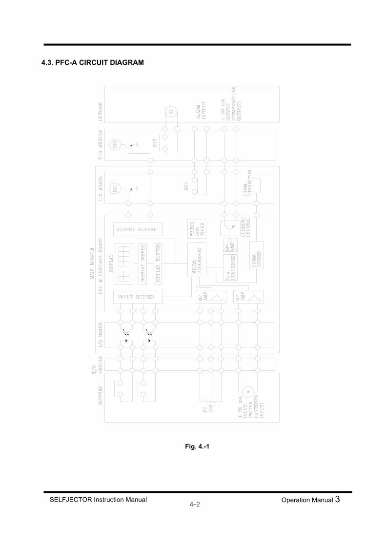
4.3. PFC-A CIRCUIT DIAGRAM
Fig. 4.-1
SELFJECTOR Instruction Manual Operation Manual 3

5. FRONT PANEL FUNCTION OF THE AUTOMATIC CONTROL PANEL
The front panel configuration and functions of the automatic control panel are described below.
Fig 5.-1
5.l. SWITCHES AND PUSH BUTTONS IN THE FRONT OF THE CONTROL PANEL CONT. SOURCE OFF / ON① As a switch on the auto control panel, it turns ON / OFF power source of the auto control panel.
EM'CY STOP② As a push button on the auto control panel, it stops a purifier directly.
SELFJECTOR Instruction Manual Operation Manual 3
5.6
5.6
5.4
5.2
5.1.③
5.1.①
5.1.②
5-1

MM FUNCTION OFF/ONThis selector switch is used for ON/OFF control of feeding signal output from the control panel tothe Multi-Monitor. When the "MM FUNCTION SWITCH" is off position, feeding signal is not outputted from the controlto the Multi-Monitor even if the SELFJECTOR is on feeding.
5.2. PUSH BUTTONS ON PFC-A AUTO START
As a luminescent push button switch, it starts automatic purifying, and the indicatinglamp is on while automatic purifying is operating.
AUTO STOP As a luminescent push button switch, it pauses automatic purifying and stops thepurifier after discharging sludge completely.
DIS. TEST As a luminescent push button switch, it has a function to discharge sludge, and it can beoperated during feeding cycle of the purifier, and discharges sludge. Also, in thetimer/counter setting mode, use this key to move the cursor to the left digit.
ALARM RESET As a luminescent push button switch, it functions as a common alarm lamp and as analarm reset. The indicating lamp is on when an alarm is happened, and off when reset by a push after the alarm is removed.
MON. As a push button switch, use this switch when you monitor the proceeding condition of functions (timer, counter) which you want to execute.
SET As a push button switch, use this switch together with "ENT" switch to set or to changethe value of a timer or a counter.
SELFJECTOR Instruction Manual Operation Manual 35-2
AUTOSTART
AUTOSTOP
DIS.T
ALARMRESET
MON
SET

ENT As a push button switch, use this switch together with "SET" switch to set or to changethe value of a timer or a counter.ENT
,As a push button switch, use this switch to seek addresses of needed timer or counter.
5.3. PILOT LAMP FOR INDICATING ON PFC-AAs pilot lamps, it shows present states of input and output. Especially, whenKT-PFC-A is in abnormal state, "CPU RUN" lamp is turned off and every output is blocked.
5.4. DISPLAY WINDOW IN THE FRONT OF PFC-A
Placed on the upper part of the right on KT-PFC-A, it indicates thetype of control or the values of a timer or a counter.
5.5. THE FUNCTION OF EACH MODULE OF PFC-A
Table 5-1
SV1
Display & CPU Module
I/O Module T/B Module Power Supply
It changes or sets the values of a timeror a counter, indicatesthe states of I/O and control panel generally.
It transmits theinputs of a sensor or aswitch to display & CPU module, controlscommands from display & CPU module and outputs to T/Bmodule.
Connecting with I/O modules, there is a terminal block toenable to connect withyard cable.
It supplies controlsource of PFC which conducts generalcontrols of autocontrol panel.
SELFJECTOR Instruction Manual Operation Manual 3

5.6. THE FUNCTION OF PILOT LAMPS OF PFC DISPLAY MODULE
1) INPUT
MOTOR RUN : Stay ON during operation of the motor of the SELFJECTOR.
2) OUTPUT
SV1 : Comes on when solenoid valve for water for opening bowl is energized (for total discharge).
SV2 : Comes on when solenoid valve for water for closing bowl is energized.
SV3 : Comes on when solenoid valve for sealing water / replacement water is energized.
SV4 : Comes on when solenoid valve for feed valve is energized.
SV9 : Comes on when solenoid valve for water for opening bowl is energized (for partial discharge).
(GSH-1 Type only)Comes on when series operation mode.
(Option Specification)
3) ALARM
LEAKAGE ALARM : Comes on when feed liquid or light liquid has accidentally flowed.
NO-DIS. ALARM : Comes on when sludge discharge is faulty.(GBC-1 Type option)
HIDENS ALARM : Comes on when error signal from Water Detector control unit is inputted.
(GSH-1 Type only) T(H) : Comes on when the processing oil at the inlet of the purifier has a high temperature.
T(L) : Comes on when the processing oil at the inlet of the purifier has a low temperature.
VIB-AL : Comes on when the vibration switch is activated. (Detector : option)
SELFJECTOR Instruction Manual Operation Manual 3

6. SETTING PROCEDURES FOR OPERATION
6.1 TIMER AND COUNTER
SELFJECTOR Instruction Manual Operation Manual 3
Repeat pushing the arrow marked buttonuntil number of timer or counter which youwant to set is displayed on indicator ofADDR.
DATAADDR.
ENT
ADDR.
ADDR.
DATA
NOTE
ADDR. TIMER or COUNTER
UNIT ADDR. TIMER or COUNTER
UNIT ADDR. TIMER or COUNTER
UNIT
000 TIMER sec 011 TIMER sec 016 TIMER sec001 TIMER sec 012 TIMER sec 022 COUNTER min002 TIMER sec 013 TIMER sec 023 COUNTER times003 TIMER sec 014 COUNTER min 026 COUNTER min004 TIMER sec 015 COUNTER min 027 COUNTER times
Press SET button.
Input the setting value by , button.
(Use button to move the cursor to the left)
Push ENT button
DATA

6.2 TIMER AND COUNTER MONITORING
Repeat pushing the arrow marked button until the number of timer or counter which you want to monitor is displayed on indicator of ADDR.
ADDR. DATA
ADDR. DATA
Push “MON” button
NOTE 1. This is convenient to know the elapsed time during purifying operation. For example, when
it is counted 1 time, indicator of DATA indicates 0001. 2. By pressing the “MON” button on automatic operation when “tP” is displayed on indicator
of ADDR, the operating status of the timers can be monitored in sequence. 3. As other buttons except “MON” button are not operated during monitoring, push “MON”
button again and change the values of timer or counter into another values or monitor the other timer or counter.
▼ ▲
6-2SELFJECTOR Instruction Manual Operation Manual 3

NOTE Counters in minute unit can be converted into 0.1 second unit with ▼, ▲ button while monitoring.
.
6-3SELFJECTOR Instruction Manual Operation Manual 3
ADDR. DATA
Unit : minute
Change the unit from minute to 0.1 second or from 0.1 second to minute.
DATA ADDR.
Unit : minute
NOTE The counters which can be monitored in the both of 0.1 second and minute unit are as follow:
ITEM Counter No. Intermittent water supply C014 Discharge interval C015 Monitoring time C022 Detection counter reset C026
The others are monitored in 1 second unit only.
▲ ▼

6.3 TEMPERATURE ALARM
6-4SELFJECTOR Instruction Manual Operation Manual 3
Repeat pushing the arrow marked button until tL(Temperature low) or tH(Temperature high) which you want to is displayed on indicator of ADDR.
ENT
ADDR. DATA
Input the setting value by ▼, ▲button
(Use ←button to move the cursor to the left)
Push “ENT” button
ADDR. DATA
Unit : °C
Unit : °C
Press “SET” button
DATAADDR.
NOTE
If Temp. high or Temp. low alarm are unnecessary, set “PASS” “PASS” is indicated by setting 201 °C.
▲ ▼

6.4 TEMPERATURE MONITORING
6-5SELFJECTOR Instruction Manual Operation Manual 3
Repeat pushing the arrow marked button until tL(Temperature low) or tH(Temperature high) which you want to is displayed on indicator of ADDR.
ADDR. DATA
Push “MON” button
ADDR. DATA
Unit : °C
Unit : °C
NOTE
As other button except “MON” button are not operated during monitoring , push “MON” button again and change the values of timer or counter into another values on monitor the other timer or counter.
Maximum setting value : from 0 °C to 200 °C
▲ ▼

6.5 SERIES OPERATION
6-6SELFJECTOR Instruction Manual Operation Manual 3
Repeat pushing the arrow marked button until “So” is displayed on indicator of ADDR.
ENT
ADDR.
ADDR.
DATA
DATA
Press “SET” button.
Input the setting value by ▼, ▲button.
Push “ENT” button.
ADDR. DATA
▲ ▼

7. TIMER SETTING TIMES The times to be set for the timers vary with following factors.
h Model number of SELFJECTOR h Type of feed oil h Operating water pressure and sealing water pressure
It is therefore necessary to set the timers to match the field conditions. When a test run and adjustments are performed by Samgong service personnel, the timers are set to the proper values suitable for the field conditions before handover. If changes occur in the properties of feed oil thereafter, refer to the following explanations and change the set times properly.
Timer Numbers and Uses Table 7-1
Timer NO. Use Time that can be set
T000 Operation intervals of each solenoid valve 0.0 ∼ 999.9 s
T001 Bowl opening time (Total discharge) 0.0 ∼ 999.9 s
T002 Replacement water supply time (Total discharge) 0.0 ∼ 999.9 s
T003 Sealing water (regulating water) supply time (Total discharge) 0.0 ∼ 999.9 s
T004 Bowl washing water supply time 0.0 ∼ 999.9 s
T011 Bowl opening time(Partial discharge) 0.0 ∼ 999.9 s
T012 Replacement water supply time (Partial discharge) 0.0 ∼ 999.9 s
T013 Sealing water(regulating water) supply time (Partial discharge) 0.0 ∼ 999.9 s
C014 Intermittent bowl closing water supply intervals 1 ∼ 9999 min
C015 Sludge discharge intervals 1 ∼ 9999 min
T016 Operating water supply for closing bowl 0.0 ∼ 999.9 s
C022 MONITORING time 1 ∼ 9999 min
C026 Water detection count reset time 1 ∼ 9999 min
Counter Numbers and Uses Table 7-2
Operation Manual 3SELFJECTOR Instruction Manual
Timer NO. Use Time that can be set
C023 Bowl washing counter 1 ~ 100 times
C027 Water detection count 1 ∼ 9999 times
7-1

7.1. GBC-1 TYPE
Standard Setting Times for Timers Table 7-3
NOTE
1. The times for sealing water and replacement water timers shown in the table assume that
the supply flow rate is 8L/min for the SJ10G-30G, 12L/min for the SJ50G-70G, 16L/min for
the SJ100G-120G, and 18L/min for the SJ150G. Be sure to measure he actual flow rate
and set the times to proper values.
2. There is not a washing process in the case of the fuel oil purifier.
Table 7-4 shows the general discharge intervals for processing fuel oil and lubricating oil. The table is
intended for general guidance.
Table 7-4
Fuel oils Lubricating oils
Fuel oil A Fuel oil C
(380mm2/s at 50°C)
Cross-head
engine
Trunk piston
engine
Sludge discharge times
(times/day) 12 24 12 24
Discharge interval
(min) 120 60 120 60
Bowl washing times
(times/day) 0 0 2 4
SELFJECTOR Instruction Manual Operation Manual 3
Item Model SJ10G SJ20G SJ30G SJ50G SJ60G SJ70G SJ100G SJ120G SJ150G
Interval T000 sec 15 15 15 15 15 15 20 20 20
Opening bowl T001 sec 3
Replacement water T002 sec 5 8 12 14 14 19 29 29 32
Sealing water T003 sec 9 10 12 18 18 20 32 32 27
Fuel oil 0Bowlwashing
water Lub. oil T004 sec
12 13 19 26 26 31 48 48 47
Intermittent watersupply
C014 min 10
Operating water supplyfor closing bowl
T016 sec 5
Discharge interval C015 min Refer to the Table 7-4
Fuel oil 0Bowlwashingcounter Lub. oil
C023 times6

7.2. GSH-1 TYPE 7.2.1 HIDENS OPERATION
Standard Setting Times for Timers Table 7-5
NOTE 1 : For discharge intervals, refer to Table 7-5 standard discharge intervals for general guidance.
NOTE 2 : Please use C021 by fixing to 1.
7-3SELFJECTOR Instruction Manual Operation Manual 3
Item Model SJ10G SJ20G SJ30G SJ50G SJ60G SJ70G SJ100G SJ120G SJ150G
Inerval T000 sec 15 15 15 15 15 15 20 20 20
Opening bowl T001 sec 3
Replacement water T002 sec 10 11 14 21 21 26 38 38 37
Fuel Oil 0 Regulating water Lub. Oil
T003 sec 1 1 2 3 3 3 5 5 5
Fuel Oil 0 Bowl washing water Lub. Oil
T004 sec 12 13 19 26 26 31 48 48 47
Opening bowl(partial) T011 sec 0.6
Replacement water (partial)
T012 sec 2 2 2 3 3 6 6 6 6
Fuel Oil 0 Regulating water (partial) Lub. Oil
T013 sec 1 1 2 3 3 3 5 5 5
Intermittent water supply
C014 min 15
Operating water supply for closing bowl
T016 sec 5
Discharge interval C015 min Refer to the Table 7-7
Monitoring time C022 min 20
Fuel Oil 0 Bowl washing counter Lub. Oil
C023 times 6
Detection count reset C026 min 30
Water detection setting counter
C027 times 6
NOTE 1. Timer setting for sealing water and replacement water in the above list are based on the
feed rate at 8 L/min for SJ10GH to 30GH, at 12 L/min for SJ50GH to 70GH, at 16 L/min for SJ100GH and 120GH and at 18 L/min for SJ150GH. For practical setting, always measure the flow rate actually and select proper values accordingly.
2. Fuel oil purifier have no regulating water feeding process and bowl washing processes.
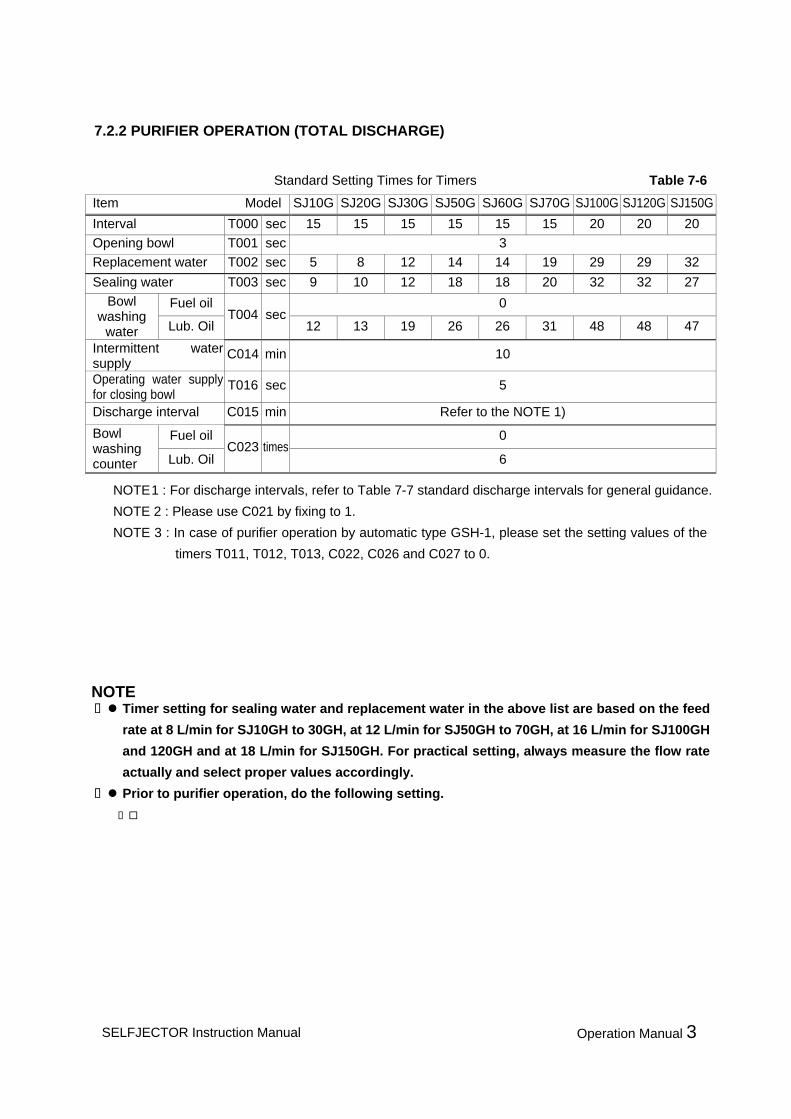
7.2.2 PURIFIER OPERATION (TOTAL DISCHARGE)
Standard Setting Times for Timers Table 7-6
NOTE 1 : For discharge intervals, refer to Table 7-7 standard discharge intervals for general guidance. NOTE 2 : Please use C021 by fixing to 1. NOTE 3 : In case of purifier operation by automatic type GSH-1, please set the setting values of the
timers T011, T012, T013, C022, C026 and C027 to 0.
Item Model SJ10G SJ20G SJ30G SJ50G SJ60G SJ70G SJ100G SJ120G SJ150GInterval T000 sec 15 15 15 15 15 15 20 20 20 Opening bowl T001 sec 3 Replacement water T002 sec 5 8 12 14 14 19 29 29 32
Sealing water T003 sec 9 10 12 18 18 20 32 32 27 Fuel oil 0 Bowl
washing water Lub. Oil
T004 sec 12 13 19 26 26 31 48 48 47
Intermittent water supply
C014 min 10
Operating water supply for closing bowl
T016 sec 5
Discharge interval C015 min Refer to the NOTE 1)
Fuel oil 0 Bowl washing counter Lub. Oil
C023 times 6
SELFJECTOR Instruction Manual Operation Manual 3
NOTE Timer setting for sealing water and replacement water in the above list are based on the feed
rate at 8 L/min for SJ10GH to 30GH, at 12 L/min for SJ50GH to 70GH, at 16 L/min for SJ100GH and 120GH and at 18 L/min for SJ150GH. For practical setting, always measure the flow rate actually and select proper values accordingly.
Prior to purifier operation, do the following setting. Select the gravity disc to match the type of oil to be treated.(Refer to Operation Manual 2) Fully Close the circulation line back pressure valve attached to the purifier and fully open
the shut off valve. Set the Water Detector selector dial to Water / heavy liquid detector function position and
the Water Detection output switch to OFF. (Refer to Operation Manual 2)
7-4

Table 7-7 shows the standard discharge intervals for general guidance in processing fuel and lubricating
oils.
Table 7-7
Fuel oils Lubricating oils
Fuel oil A Fuel oil C
(380mm2/s at 50˚C)
Cross-head
engineTrunk piston engine
HIDENS
Operation 120 min 60 min 120 min 60 min
Purifier
Operation 120 min 60 min 120 min 60 min
7.2.3 COUNTER SETTING VALUES
The inside of the bowl can be cleaned after every few total discharge operation in order to remove
unevenly accumulated sludge and dirt.
Table 7-8 shows the standard bowl washing counters for general guidance in processing fuel and
lubricating oils.
Table 7-8
Fuel oils Lubricating oils
Fuel oil A Fuel oil C
(380mm2/s at 50˚C)
Cross-head
engineTrunk piston engine
Bowl
washing
counter
0 times 0 times 6 times 6 times
NOTEThe Bowl washing count shown above is set so that washing interval will be 24 hours.
The Bowl washing interval is given by : (Except when the Bowl washing count is 0.)
The Bowl washing interval (min)
= Discharge interval (C015) x Total discharge count (C021) x Bowl washing count (C023)
SELFJECTOR Instruction Manual Operation Manual 3

8. AUTOMATIC OPERATION(GBC-1)
8.1 OPERATION PREPARATION
8.2 AUTOMATIC OPERATION(GBC-1 TYPE)Step 1. Start the SELFJECTOR by separately installed starter.
Step 2. Set the power switch on the automatic control panel to "ON".
Step 3. Set the timer and the counter in the panel.
Step 4. The CONT. SOURCE pilot lamp will come on. Check the ammeter of the starter to confirm that the SELFJECTOR has reached the ratedspeed. Thereafter, press pushbutton AUTO START provided on the control panel.
Step 5. Each timer of purifier controller in the automatic control panel works in the following order toperform continuous purifier operation.(Refer to the attached Section Automatic Operation Flow and 8.6. Timing Chart as well.)
The interval timer T000 starts operation. Solenoid valve SV2 will open to supply the bowl closing water and close the bowl.
When T000 is timed up. Solenoid valve SV2 will be deactivated to stop supplying the bowl closing water. Solenoid valve SV3 will be activated to supply the replacement water into the bowl.At the same time, the replacement water timer T002 will start operation.
When T002 is timed up. Solenoid valve SV3 will be deactivated to stop supplying the replacement water. Solenoid valve SV1 will be activated to supply the bowl opening water, and thebowl will be opened to discharge replacement water.
At the same time, the bowl opening water supply time setting timer T001 willstart operation.
CAUTION
Refer to Table 7-3, 7-4 and make sure that each timer is set to appropriate values for actualoperating conditions(feed oil type, SELFJECTOR model number, and available water pressureand etc.).Specifically, the discharge interval time "C015" should be set to fit the sort of feed oil since thetimer influences the amount of sludge accumulated in the bowl. (for the change of set timer, refer to Table 7-4).When you perform setting change of an option function, please turn [OFF] the power supply of acontrol panel for safety.Make sure that the selection of the gravity disc is correct.Make sure position of the switches in the Multi-Monitor(MM) is right. Make sure the set pressure value of the operating water reducing valve is right.
For the SELFJECTOR main unit and relevant valves refer to the separate "Operation Manual2".
Operation Manual 3SELFJECTOR Instruction Manual
!
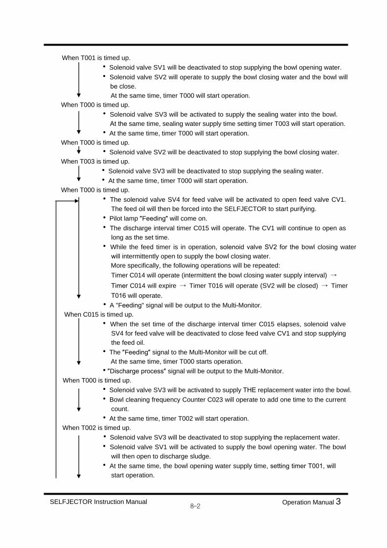
When T001 is timed up. Solenoid valve SV1 will be deactivated to stop supplying the bowl opening water. Solenoid valve SV2 will operate to supply the bowl closing water and the bowl willbe close.At the same time, timer T000 will start operation.
When T000 is timed up. Solenoid valve SV3 will be activated to supply the sealing water into the bowl.At the same time, sealing water supply time setting timer T003 will start operation.
At the same time, timer T000 will start operation. When T000 is timed up.
Solenoid valve SV2 will be deactivated to stop supplying the bowl closing water.When T003 is timed up.
Solenoid valve SV3 will be deactivated to stop supplying the sealing water. At the same time, timer T000 will start operation.
When T000 is timed up. The solenoid valve SV4 for feed valve will be activated to open feed valve CV1. The feed oil will then be forced into the SELFJECTOR to start purifying.
Pilot lamp Feeding will come on. The discharge interval timer C015 will operate. The CV1 will continue to open as long as the set time.
While the feed timer is in operation, solenoid valve SV2 for the bowl closing waterwill intermittently open to supply the bowl closing water.
More specifically, the following operations will be repeated:Timer C014 will operate (intermittent the bowl closing water supply interval) Timer C014 will expire Timer T016 will operate (SV2 will be closed) Timer T016 will operate.
A "Feeding" signal will be output to the Multi-Monitor.When C015 is timed up.
When the set time of the discharge interval timer C015 elapses, solenoid valveSV4 for feed valve will be deactivated to close feed valve CV1 and stop supplyingthe feed oil.
The Feeding signal to the Multi-Monitor will be cut off. At the same time, timer T000 starts operation. Discharge process signal will be output to the Multi-Monitor.
When T000 is timed up. Solenoid valve SV3 will be activated to supply THE replacement water into the bowl. Bowl cleaning frequency Counter C023 will operate to add one time to the current
count. At the same time, timer T002 will start operation.
When T002 is timed up. Solenoid valve SV3 will be deactivated to stop supplying the replacement water. Solenoid valve SV1 will be activated to supply the bowl opening water. The bowl
will then open to discharge sludge. At the same time, the bowl opening water supply time, setting timer T001, will
start operation.
SELFJECTOR Instruction Manual Operation Manual 3

When T001 is timed up Solenoid valve SV1 will be deactivated to stop supplying the bowl opening water. Solenoid valve SV2 will operate to supply the bowl closing water and the bowl willbe closed.
At the same time, timer T000 will start operation.
When T000 is timed up. Solenoid valve SV3 will be activated to supply the sealing water into the bowl. At
the same time, sealing water supply time setting timer T003 will start operation At the same time, timer T000 will restart operation. The Discharge process signal output to the Multi-Monitor will be stopped.
(Optional Specification) The reset coil signal will be output to the vibration switch for a second.(Optional Specification)
When T000 is timed up. Solenoid valve SV2 will be deactivated to stop supplying the bowl closing water.
When T003 is timed up. Solenoid valve SV3 will be deactivated to stop supplying the sealing water. At the same time, timer T000 will start operation.
When T000 is timed up(when counter C023 is counting). Timer T000 will restart operation. The Discharge process signal output to the Multi-Monitor will be stopped.
(Optional Specification) When T000 is timed up.
Solenoid valve SV2 will be deactivated to stop supplying the bowl closing water. Solenoid valve SV3 will open to supply the cleaning water into the bowl. At the same time, timer T004 will start operation.
When T004 is timed up. Solenoid valve SV3 will be deactivated to stop supplying the bowl cleaning water. Solenoid valve SV1 will operate to supply the bowl opening water, and the bowl willbe opened to discharge the cleaning water.
At the same time, timer T001 will start operation. When T001 is timed up.
Solenoid valve SV1 will be deactivated to stop supplying the bowl opening water. Solenoid valve SV2 will be operate to supply the bowl closing water, and bowl willbe closed. At the same time, timer T000 will start operation.
When T000 is timed up.
SELFJECTOR Instruction Manual Operation Manual 3

8.3. SLUDGE DISCHARGE TEST
During feeding operation, a sludge discharge test can be performed at any time irrespective of the elapse feed time. When push button DIS-TEST on the automatic control panel is pressed, theSELFJECTOR will enter the sludge discharge process in the same way as upon expiry of the discharge interval timer (C021).
As soon as the sludge discharge process is completed, the SELFJECTOR will directly be restoredto the automatic operation.
8.4. AUTOMATIC STOP
Press push button AUTO STOP on the automatic control panel.The SELFJECTOR will automatically stop operation after completion of the sludge dischargeprocess.
8.5. EMERGENCY STOP
CAUTION
When the SELFJECTOR is shut down because of an emergency, No opening Bowl, abnormalvibration or overload, it will stop operation without discharging the sludge accumulated in thebowl. If the SELFJECTOR is directly restarted, the bowl might lose balance and cause ahazardous situation. For this reason, be sure to disassemble the bowl and remove the sludge according to Operation Manual 2 before restarting operation.
CAUTION
The automatic control panel is electrically interlocked with the starter. Therefore, the automaticcontrol panel is not operable unless the SELFJECTOR is started by the starter.To operate the SELFJECTOR, without using the automatic control panel, manually operate theindividual solenoid valves.
In cases of emergency, press push button "EM'CY STOP" on the automatic control panel.In any of the processes, the power supply to the SELFJECTOR will be cut off, and all the solenoid valves will be closed to stop operation.
SELFJECTOR Instruction Manual Operation Manual 3
!
!

8.6. TIMING CHART (GBC-1 TYPE)
8.6.1 AUTOMATIC OPERATION & STOPPING
SELFJECTOR Instruction Manual Operation Manual 3

8.6.7 BOWL WASHING
8-6SELFJECTOR Instruction Manual Operation Manual 3

9. AUTOMATIC OPERATION(GSH-1)
9.1. OPERATION PREPARATION
CAUTION
Refer to Table 7-5, 7-6, 7-7, 7-8 and make sure that each timer is set to appropriate values for actualoperating conditions (feed oil type, SELFJECTOR model number, and available water pressure and etc.). Specifically, the discharge interval timer "C015" should be set to fit the sort of feed oil since the timerinfluences the amount of sludge accumulated in the bowl.(For the change of set timer, refer to Table 7-7).
For the SELFJECTOR main unit and relevant valves refer to the separate "Operation Manual 2". Make sure that the gravity disc for HIDENS is installed in the SELFJECTOR.Make sure that the circulation line back pressure valve is fully opened and shut off valve is fully closedattached to the SELFJECTOR.
Make sure position of the switch in the Multi-Monitor(MM)is right.(Water detector selector dial, Waterdetection output switch and etc). Make sure the set pressure value of the operating water reducing valve is right.
9.2. HIDENS SYSTEM OPERATIONStep 1. Start the SELFJECTOR by separately installed starter.
Step 2. Set the power switch on the automatic control panel to "ON".
Step 3. Set the timer and counter in the panel.
Step 4. The CONT. SOURCE pilot lamp will come on. Check the ammeter of the starter to confirm that the SELFJECTOR has reached the ratedspeed. Thereafter, press push button AUTO START provided on the control panel.
Step 5. Each timer of purifier controller in the automatic control panel works in the following order toperform continuous purifier operation.(Refer to the attached Section Automatic Operation Flow and 9.7. Timing Chart as well.)
The interval timer T000 begins working. Solenoid valve SV2 will open to supply the bowl closing water and close the bowl.
When T000 is timed up. Solenoid valve SV2 will close to stop supplying the bowl closing water. Solenoid valve SV3 will open to supply the replacement water. Replacement water timer T002 will start operation.
When T002 is timed up. Solenoid valve SV3 will close to stop supplying the replacement water. Solenoid valve SV1 will open to supply the bowl opening water and open the bowl. Bowl opening water timer T001 will start operation.
SELFJECTOR Instruction Manual Operation Manual 3
!

When T001 is timed up. Solenoid valve SV1 will close to stop supplying the bowl opening water. Solenoid valve SV2 will open to supply the bowl closing water and close the bowl.At the same time, interval timer T000 will start operation.
When T000 is timed up. Solenoid valve SV3 will open to supply the regulating water. Regulating water timer T003 will start operation.
At the same time, interval timer T000 will restart operation. When T003 is timed up.
Solenoid valve SV3 will close to stop supplying the regulating water. When T000 is timed up.
Solenoid valve SV2 will close to stop supplying the bowl closing water. Interval timer T000 will restart operation.
When T000 is timed up. Solenoid valve SV4 will open to supply operating air and open the feed valve to
supply the feed oil into the bowl and start purifier operation. At the same time,discharge interval timer C015 will restart operation.
During operation of the discharge interval timer C015, the bowl closing water will be intermittently supplied.In other words, the following processes will be repeated: Operation C014 Expiry of C014 Operation of T016(open SV2 to supply the bowl closing water)Expiry of T016(closes SV2 to stop supplying the bowl closing water) Operation ofC014
The Feeding signal will be output to the Multi-Monitor.
When a water detection signal is received from Multi-Monitor(When the Monitoring timer C022 have expired.), or when C015 timer expires,
Discharge interval timer C015 will be reset. Monitoring timer C022 will be reset. Solenoid valve SV4 will close to close the feed valve. At the same time, interval timer T000 will start operation. The Feeding signal output to the Multi-Monit.or will be stopped. The Discharge process" signal will be output to the Multi-Monitor.
When T000 is timed up. Solenoid valve SV3 will open to supply the replacement water. Replacement water timer T002 will start operation. The bowl washing counter C023 is counted one time and is added one time to the
current count. When T002 is timed up.
Solenoid valve SV3 will close to stop supplying the replacement water. At the same time, solenoid valve SV1 will open to supply the bowl opening water
and open the bowl to discharge sludge. Bowl opening water timer T001 will start operation.
NOTEThe fuel oil purifier dose not require the supply of Regulating water.
SELFJECTOR Instruction Manual Operation Manual 3

When T001 is timed up. Solenoid valve SV1 will close to stop supplying the bowl opening water. Solenoid valve SV2 will open to supply the bowl closing water and close the bowl.At the same time, interval time T000 will start operation.
When T000 is timed up(When the Bowl washing counter C023 have expired). Interval timer T000 will restart operation. Output of the "Discharge process" signal to the Multi-Monitor is stopped.
When T000 is timed up. The solenoid valve SV3 opens to supply the bowl washing water. Solenoid valve SV2 will close to stop supplying the bowl closing water. Bowl washing water timer T004 begins operating.
When T004 is timed up. Solenoid valve SV3 will close to stop supplying the bowl washing water. At the same time, solenoid valve SV1 will open to supply the bowl opening waterand open the bowl to discharge washing water.
Bowl opening water timer T001 will start operation.When T001 is timed up.
Solenoid valve SV1 will close to stop supplying the bowl opening water. Solenoid valve SV2 will open to supply the bowl closing water and close the bowl. At the same time, interval timer T000 will start operation.
When T000 is timed up. Solenoid valve SV3 will open to supply the regulating water.
Regulating water timer T003 will start operation. Interval timer T000 will restart operation.
When T003 is timed up. Solenoid valve SV3 will close to stop supplying the regulating water.
When T000 is timed up Solenoid valve SV2 will close to stop supplying the bowl closing water. Interval timer T000 will restart operation.
When T000 is timed up(When the bowl washing counter C023 have not expired.). Solenoid valve SV3 will open to supply the regulating water. Regulating water timer T003 will start operation. The Discharge process signal output to the Multi-Monitor will be stopped.
Interval timer T000 will restart operation.
NOTEThe fuel oil purifier dose not require the supply of Regulating water.
NOTEThe fuel oil purifier dose not require the supply of Regulating water.
SELFJECTOR Instruction Manual Operation Manual 3
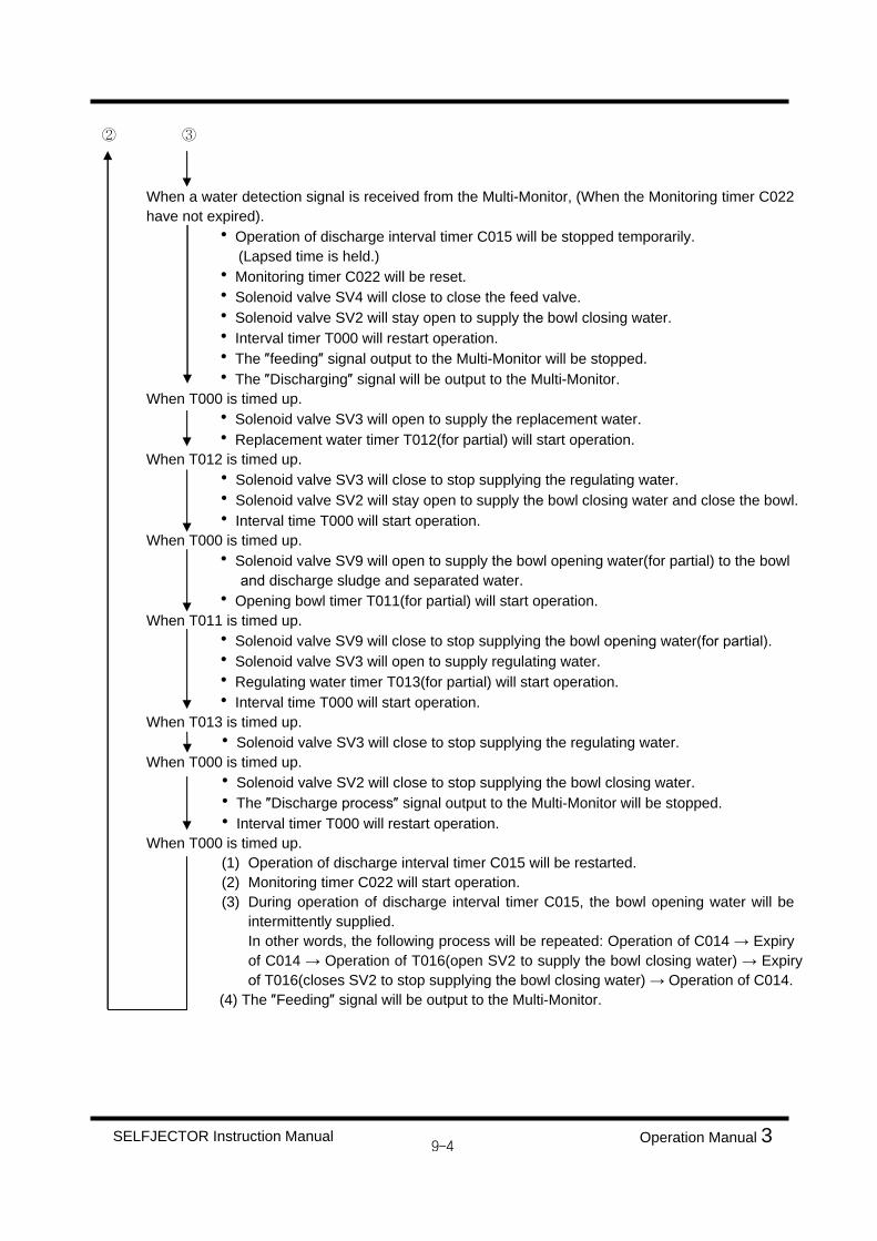
When a water detection signal is received from the Multi-Monitor, (When the Monitoring timer C022 have not expired).
Operation of discharge interval timer C015 will be stopped temporarily. (Lapsed time is held.)
Monitoring timer C022 will be reset. Solenoid valve SV4 will close to close the feed valve. Solenoid valve SV2 will stay open to supply the bowl closing water. Interval timer T000 will restart operation. The feeding signal output to the Multi-Monitor will be stopped. The Discharging signal will be output to the Multi-Monitor.
When T000 is timed up. Solenoid valve SV3 will open to supply the replacement water. Replacement water timer T012(for partial) will start operation.
When T012 is timed up. Solenoid valve SV3 will close to stop supplying the regulating water. Solenoid valve SV2 will stay open to supply the bowl closing water and close the bowl. Interval time T000 will start operation.
When T000 is timed up. Solenoid valve SV9 will open to supply the bowl opening water(for partial) to the bowl
and discharge sludge and separated water. Opening bowl timer T011(for partial) will start operation.
When T011 is timed up. Solenoid valve SV9 will close to stop supplying the bowl opening water(for partial). Solenoid valve SV3 will open to supply regulating water. Regulating water timer T013(for partial) will start operation. Interval time T000 will start operation.
When T013 is timed up. Solenoid valve SV3 will close to stop supplying the regulating water.
When T000 is timed up. Solenoid valve SV2 will close to stop supplying the bowl closing water. The Discharge process signal output to the Multi-Monitor will be stopped. Interval timer T000 will restart operation.
When T000 is timed up. (1) Operation of discharge interval timer C015 will be restarted.(2) Monitoring timer C022 will start operation.(3) During operation of discharge interval timer C015, the bowl opening water will be
intermittently supplied. In other words, the following process will be repeated: Operation of C014 Expiry of C014 Operation of T016(open SV2 to supply the bowl closing water) Expiryof T016(closes SV2 to stop supplying the bowl closing water) Operation of C014.
(4) The Feeding signal will be output to the Multi-Monitor.
SELFJECTOR Instruction Manual Operation Manual 3

9.3. PURIFIER OPERATION
Step 1. Start the SELFJECTOR by the separately mounted starter.
Step 2. Set the power switch provided on the control panel to "ON".
Step 3. The ADDR , DATA displayed on indicator.
Step 4. Check the ammeter of the start to confirm that the SELFJECTOR has reached the rated speed. Thereafter, press push button AUTO START provided on the control panel. Pilot lamp will come on.
Step 5. The timers in the controller provided in the control panel will operate in the following sequenceto perform continuous purifier operation.
The interval timer T000 starts operation. Solenoid valve SV2 will open to supply the bowl closing water and close the bowl.
When T000 is timed up. Solenoid valve SV2 will be deactivated to stop supplying the bowl closing water. Solenoid valve SV3 will be activated to supply the replacement water into the bowl.At the same time, the replacement water timer T002 will start operation.
When T002 is timed up. Solenoid valve SV3 will be deactivated to stop supplying the replacement water. Solenoid valve SV1 will be activated to supply the bowl opening water, and thebowl will be opened to discharge the replacement water.
At the same time, the bowl opening water supply time, setting timer T001, willstart operation.
When T001 is timed up. Solenoid valve SV1 will be deactivated to stop supplying the bowl opening water. Solenoid valve SV2 will operate to supply the bowl closing water and the bowl willbe closed.At the same time, interval timer T000 will start operation.
When T000 is timed up. Solenoid valve SV3 will be activated to supply teh sealing water into the bowl. Sealing water supply time setting timer T003 will start operation. At the same time, interval timer T000 will restart operation.
CAUTION
When SJ10GH to SJ150GH types are used in the total discharge mode (purifier operation), select anappropriate gravity disc that fits the specific gravity of feed liquid and install it in position. Then, fully open the shut off valve and fully close the circulation line back pressure valve. After that, set theWater Detector selector dial to No working position and the water detection output switch to OFF position.
SELFJECTOR Instruction Manual Operation Manual 3
!

When T000 is timed up. Solenoid valve SV2 will be deactivated to stop supplying the bowl closing water.
When T003 is timed up. Solenoid valve SV3 will be deactivated to stop supplying the sealing water. At the same time, timer T000 will start operation.
When T000 is timed up. (1) Solenoid valve SV4 will open to send the operating air to open the feed valve and
feed the feed oil into the bowl to perform purifier operation. At the same time,discharge interval timer C015 will start operation.
During operation of the discharge interval timer C015, the bowl opening water willbe intermittently supplied.In other word, the following processes will be repeated: Operation of C014 Expiry of C014 Operation of T016(opens SV2 to supply bowl closing water) Expiry of T016(closes SV2 to stop supplying bowl closing water) Operation of C014.
(3) The Feeding signal will be output to the Multi-Monitor.When C015 is timed up.
Discharge interval timer C015 will be reset. Solenoid valve SV4 will close to close the feed valve. At the same time, interval timer T000 will start operation. The Feeding signal output to the Multi-Monitor will be stopped. The Discharge process signal will be output to the Multi-Monitor.
When T000 is timed up. Solenoid valve SV3 will open to supply the replacement water into the bowl. Bowl cleaning frequency counter C023 will operate to add one time to the current
count. Replacement water timer T002 will start operation.
When T002 is time up. Solenoid valve SV3 will close to stop supplying the replacement water. At the same time, solenoid valve SV1 will open to supply the bowl opening water and open the bowl to discharge sludge.
Bowl opening water timer T001 will operate. When T001 is timer up
Solenoid valve SV1 will close to stop supplying the bowl opening water. Solenoid valve SV2 will open to supply bowl closing water and the bowl will be
closed. At the same time, timer T000 will start operation.
When T000 is timed up(when the bowl washing counter C023 have expired.) Interval timer T000 will restart operation. The Discharge process signal output to the Multi-Monitor will be stopped.
When T000 is timed up. Solenoid valve SV3 will open to supply the bowl washing water. Bowl washing timer T004 will start operation. Solenoid valve SV2 will close to stop supplying the bowl closing water.
SELFJECTOR Instruction Manual Operation Manual 3

When T004 is timed up. Solenoid valve SV3 will close to stop supplying the bowl washing water. At the same time, solenoid valve SV1 will open to supply the bowl opening water and open the bowl to discharge the washing water.
The bowl opening water timer T001 will start operation.When T001 is timed up.
Solenoid valve SV1 will be close to stop supplying the bowl opening water. Solenoid valve SV2 will open to supply bowl closing water, and the bowl will be
closed. Interval timer T000 will start operation.
When T000 is timed up. Solenoid valve SV3 will open to supply the sealing water. Sealing water timer T003 will start operation. interval timer T000 will restart operation.
When T000 is timed up. Solenoid valve SV2 will close to stop supplying the bowl closing water.
When T003 is timed up. Solenoid valve SV3 will close to stop supplying the sealing water. Interval timer T000 will start operation.
When T000 is timed up(When the bowl washing counter C023 have not expired). Solenoid valve SV3 will open to supply the sealing water. Sealing water timer T003 will start operation. Interval timer T000 will restart operation. The Discharge process signal output to the Multi-Monitor will be stopped.
When T000 is timed up. Solenoid valve SV2 will close to stop supplying the bowl closing water.
SELFJECTOR Instruction Manual Operation Manual 3

9.4. SLUDGE DISCHARGE TEST
9.4.1. SLUDGE DISCHARGE TEST DURING FEEDING OPERATIONDuring feeding operation, a test can be performed to discharge the sludge from inside the bowl freely at any time regardless of the elapse of the feed time. Press push button DIS-TEST provided on the controlpanel by the following procedures. Then the SELFJECTOR will enter the Partial Discharge or TotalDischarge process to discharge sludge. After sludge has been discharged, the SELFJECTOR will continue automatic operation in the original mode.
(1) PARTIAL DISCHARGEPress the DIS-TEST push button once.
(2) TOTAL DISCHARGEPress the DIS-TEST push button twice in five seconds.
9.4.2. SLUDGE DISCHARGE TEST EXCEPTING SELFJECTOR IS IN AUTOMATIC OPERATIONWhen the SELFJCTOR is not in automatic operation, pressing the DIS-TEST push button provided onthe control panel will open the bowl closing water solenoid valve SV2 to supply the working water to closethe bowl. The partial bowl opening water solenoid valve SV9 will then continue to open for the set time ofthe partial bowl opening timer T011.This function is not used to normal operation.
9.5. AUTOMATIC STOP
When push button AUTO STOP provided on the control panel is pressed, the SELFJECTOR will automatically stop after going through the replacement water process and then discharging sludge.(During feed operation, the feed oil supply is first stopped.)
9.6. EMERGENCY STOP
In an emergency, press the push button EM'CY STOP .Whatever the process, the power supply to the SELFJECTOR is shut down, each valve is closed and the operation stops.
SELFJECTOR Instruction Manual Operation Manual 3
CAUTION
In the cases of emergency stop, defective discharge stop and overload stop, the SELFJECTORstops without discharging sludge accumulated within it. When restarting, be careful. Because it is very dangerous that the sludge within the bowl sometimes breaks the balance of bowl. By all means, refer the Instruction Manual of SELFJECTOR itself, overhaul the bowl toremove the sludge, then try to restart.
!

9.7. TIMING CHART (GSH-1 TYPE)
9.7.1 AUTOMATIC OPERATION & STOPPING (HIDENS OPERATION)
SELFJECTOR Instruction Manual Operation Manual 3

9.7.2 BOWL WASHING
SELFJECTOR Instruction Manual Operation Manual 3

9.7.3 ALARM
SELFJECTOR Instruction Manual Operation Manual 3

9.7.4 AUTOMATIC OPERATION & STOPPING (PURIFIER OPERATION)
SELFJECTOR Instruction Manual Operation Manual 3

10. ALARMS
10.1. TYPES OF ALARMS When any of the following alarms occurs, the control panel will cause pilot lamp associated to light and willtransmit an alarm signal to the remote console.
LEAK alarm - "OIL LEAKAGE" alarm
NO-DIS alarm - "NO OPENING OF BOWL" alarm (GBC-1 Type is option)HIDENS alarm - "ABNORMAL WATER CONTENT" alarm which occurs when the water detection setting counter C027 expires (GSH-1 Type is only) T(H)" alarm - "OIL INLET TEMP. HIGH" alarm, T(L)" alarm - "OIL INLET TEMP. LOW alarmVIB-AL" alarm - "ABNORMAL VIBRATION alarm (Optional specification)
10.2 RESET. ALARM
Press push button ALARM RESET provided on the control panel to reset the alarm circuit.
CAUTION
Remove the cause of an alarm before pressing push button ALARM RESET
SELFJECTOR Instruction Manual Operation Manual 3
!

10.3. ALARM AND CORRECTIVE ACTION
10.3.1 LEAK : OIL LEAKAGE ALARM
This alarm will be generated by the Leakage Monitor Function(LM) of the Multi-Monitor when thelight liquid side pressure falls due to outflow of the feed oil or processed oil toward the heavyliquid side or sludge chute side of the SELFJECTOR during feeding operation. When this alarm occurs, the SELFJECTOR will automatically stop operation after discharging sludge.
Table 10-1
Alarm Cause of alarm Process
Oilleakage
1. The bowl failed to close because of a fault in the SELFJECTOR.
2. The bowl closing water was not supplied becausesolenoid valve SV2 failed to open.
3. The required sealing water was not supplied becausesolenoid valve SV3 failed to open.
4. The required sealing water was not supplied because the set time of the sealing water timer "T003" was too short.
5. solenoid valve SV2 or SV3 failed to open because of a defective output module in the control panel.
6. Defective Multi-Monitor(MM)
7. Defective water or air system
1. Refer to the separate"Maintenance Manual".
2. Repair or replace the valvewith a non-defective one.
3. same as above.
4. Adjust the setup time of thetimer.
5. Replace the output modulewith a spare one.
6. Refer to the separate"Maintenance Manual".
7. Refer to the separate"Maintenance Manual".
SELFJECTOR Instruction Manual Operation Manual 3

10.3.2 NO-DIS : NO OPENING OF BOWL ALARM (GBC-1 Type is option)
This alarm occurs when the Discharge Detector Function(DD) of the Multi-Monitor fails to detect discharge despite the fact that a DISCHARGE SLUDGE signal was sent to the bowl openingsolenoid (SV1, SV9 (GSH-1 Type only)).When this alarm occurs, the SELFJECTOR will stop operation immediately.
Table 10-2
10.3.3 HIDENS : ABNORMAL WATER CONTENT ALARM
This alarm occurs when the water detection count is abnormally high.When the Multi-Monitor detects the water content in the bowl, its water detection signal is input tothe CPU board and a water discharge operation is effected, when the water detection setting counter (C027) adds one time to the current count. C027 is reset every time the water detectioncount reset timer(C026), which is repetitively actuated during automatic operation, expires. If thewater content of the feed oil is abnormally high, water detection is repeated within a short period of time, C027 counts up to give an abnormal water content alarm. When this signal is issued, theSELFJECTOR is automatically stopped after discharging sludge.
Alarm Cause of alarm Process
No opening ofbowl
1. The bowl failed to open because of failure of the SELFJECTOR.
2. The bowl operating water was not suppliedbecause solenoid valve SV1 or SV9 failed to open.
3. Solenoid valve SV1 or SV9 failed to open because of a defective output module in the control panel.
4. Defective Multi-Monitor(MM).
5. Defective water or air system.
6. The set pressure of the reducing valve was low, so that amount of sludge discharge was too less.
1. Refer the separate"Maintenance Manual".
2. Repair or replace the valvewith a non-defective one.
3. Replace the output module.
4. Refer the separate"Maintenance Manual".
5. Refer the separate"Maintenance Manual".
6. Refer to the separate Operationmanual2 , and adjust the reducing valve as required.
SELFJECTOR Instruction Manual Operation Manual 3

10.3.4 ″T(H)″ : OIL HIGH TEMPERATURE ALARM ″T(L)″ : OIL LOW TEMPERATURE ALARM This alarm occurs when the temperature of the processing oil becomes higher or lower during feeding operation than alarm setting value. Even if this alarm occurs, the SELFJECTOR will continue to operate. To clear the alarm, remove the cause of the alarm. Thereafter, press push button ″ALARM RESET″ on the control panel.
10.3.5 ″VIB-AL″ : ABNORMAL VIBRATION (Optional Specification) This alarm occurs when the vibration switch is operated by occurrence of an abnormal vibration in the SELFJECTOR. As soon as the alarm occurs, the SELFJECTOR will stop operation immediately. Disassemble and check the SELFJECTOR and remove the cause of the alarm. Thereafter, press push button ″ALARM RESET″ on the control panel and perform the procedures to restart operation.
Table 10-3
Alarm Cause of alarm Corrective Action
Abnormal vibration (VIB-AL)
1. Abnormal vibration of the bowl occurred because of a fault in the SELFJECTOR.
2. The vibration switch was operated
because of vibration at the time of a start or during discharge process.
3. The reset coil of the vibration switch was
not operated. 4. Vibration switch out of order.
1. Refer to the separate ″Maintenance Manual″.
2. Replace input module. 3. Replace output module. 4. Replace the switch with
a non-defective one.
10-4SELFJECTOR Instruction Manual Operation Manual 3

11. AUTOMATIC OPERATION FLOW SHEET 11.1 GBC-1 TYPE
Fig. 11-1
SELFJECTOR Instruction Manual Operation Manual 3
1 SELFJECTOR A Dirty oil inlet 2 Gear pump B Purified oil outlet 3 Solenoid valve unit for operating water
SV1 : Solenoid valve (for Bowl opening water) SV2 : Solenoid valve (for Bowl closing water) SV3 : Solenoid valve (for Sealing water)
C Compressed air inlet
4 3-way cylinder valve (Feed valve) D Sludge & water outlet 5 3-way solenoid valve (SV4 : for feed valve air supply) E Water inlet 6 Air filter (for feed valve) F Drain 7 Multi-monitor G Circulation
8 Leakage Monitor Function(LM) ⓟ Pressure gauge
9 Oil heater ⓒ Compound gauge
10 Oil Strainer ⓜ Motor 11 Flow control valve 12 Pressure control valve
11-1

11.2 GSH-1 TYPE
Fig. 11-2
1 SELFJECTOR A Dirty oil inlet 2 Gear pump B Purified oil outlet 3 Solenoid valve unit for operating water
SV1 : Solenoid valve (for Bowl opening water)SV2 : Solenoid valve (for Bowl closing water)SV3 : Solenoid valve (for Sealing water)SV9 : Solenoid valve (for Partial bowl opening water)
C Compressed air inlet
4 3-way cylinder valve (Feed valve) D Sludge & water outlet5 3-way solenoid valve (SV4 : for feed valve air supply) E Water inlet 6 Air filter (for feed valve) F Drain
G7 Multi-monitor G Circulation
8 Leakage Monitor Function(LM) Pressure gauge
9 Discharge Detector Function(DD) Compound gauge
10 Water Detector Function(WD) Motor
11 Oil heater
12 Oil Strainer13 Flow control valve14 Pressure control valve
SELFJECTOR Instruction Manual Operation Manual 3

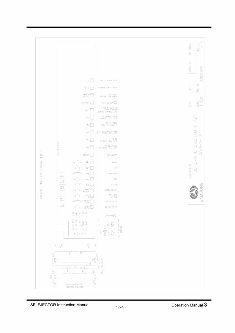
12. SCHEMATIC CONNECTION DIAGRAM
The attached drawing contains all of the optional detectors and circuits, some of which may not
be provided or used, depending on the specification for the SELFJECTOR you have purchased.
Refer to the drawing in the final drawing as well.
SELFJECTOR Instruction Manual Operation Manual 3

11.1 GBC-1 TYPE
SELFJECTOR Instruction Manual Operation Manual 3

SELFJECTOR Instruction Manual Operation Manual 3

SELFJECTOR Instruction Manual Operation Manual 3

SELFJECTOR Instruction Manual Operation Manual 3

SELFJECTOR Instruction Manual Operation Manual 3

11.2 GSH-1 TYPE
SELFJECTOR Instruction Manual Operation Manual 3

SELFJECTOR Instruction Manual Operation Manual 3

SELFJECTOR Instruction Manual Operation Manual 3
SELFJECTOR Instruction Manual Operation Manual 3

SELFJECTOR Instruction Manual Operation Manual 3

SAMGONG-MITSUBISHISELFJECTOR
GENIUS SERIES
INSTRUCTION MANUAL(OPERATION MANUAL 3)
Date of Issued : June 2004
SAMGONG CO., LTD.