Embed Size (px)
Citation preview

Operation Manual and Parts BookWessex ProLine FRX 150-HOutfront Flail Mower
Product Code: L2050
Issue March 2017
GB


CONTENTS
Welcome to your new Wessex Proline FRX 150-H . . . . . . . . . . . . . . . . . . . . . . . . . . . . . . . .2
Safety Decals . . . . . . . . . . . . . . . . . . . . . . . . . . . . . . . . . . . . . . . . . . . . . . . . . . . . . . . . . . . . .3
Important Safety Warnings . . . . . . . . . . . . . . . . . . . . . . . . . . . . . . . . . . . . . . . . . . . . . . . . . . .4
Warranty . . . . . . . . . . . . . . . . . . . . . . . . . . . . . . . . . . . . . . . . . . . . . . . . . . . . . . . . . . . . . . . . .5
Setting up your Mower . . . . . . . . . . . . . . . . . . . . . . . . . . . . . . . . . . . . . . . . . . . . . . . . . . . . . .6
Connecting the Hydraulic Coupling . . . . . . . . . . . . . . . . . . . . . . . . . . . . . . . . . . . . . . . . . . . . .6
Starting up the Mower . . . . . . . . . . . . . . . . . . . . . . . . . . . . . . . . . . . . . . . . . . . . . . . . . . . . . . .6
Setting the cutting height . . . . . . . . . . . . . . . . . . . . . . . . . . . . . . . . . . . . . . . . . . . . . . . . . . . . .7
Adjusting the Front Wheels . . . . . . . . . . . . . . . . . . . . . . . . . . . . . . . . . . . . . . . . . . . . . . . . . . .7
Adjusting the Roller . . . . . . . . . . . . . . . . . . . . . . . . . . . . . . . . . . . . . . . . . . . . . . . . . . . . . . . . .7
Maintenance . . . . . . . . . . . . . . . . . . . . . . . . . . . . . . . . . . . . . . . . . . . . . . . . . . . . . . . . . . . . . .8
Belt Adjustment . . . . . . . . . . . . . . . . . . . . . . . . . . . . . . . . . . . . . . . . . . . . . . . . . . . . . . . . . . . .8
Lubrication . . . . . . . . . . . . . . . . . . . . . . . . . . . . . . . . . . . . . . . . . . . . . . . . . . . . . . . . . . . . . . . .8
Flail Blades - Changing . . . . . . . . . . . . . . . . . . . . . . . . . . . . . . . . . . . . . . . . . . . . . . . . . . . . . .8
Winter Storage . . . . . . . . . . . . . . . . . . . . . . . . . . . . . . . . . . . . . . . . . . . . . . . . . . . . . . . . . . . . .9
Troubleshooting . . . . . . . . . . . . . . . . . . . . . . . . . . . . . . . . . . . . . . . . . . . . . . . . . . . . . . . . . . . .9
Parts Illustration - FRX 150-H Body Assembly . . . . . . . . . . . . . . . . . . . . . . . . . . . . . . . . . . .10
Parts List - FRX 150-H Body Assembly . . . . . . . . . . . . . . . . . . . . . . . . . . . . . . . . . . . . . . . .11
Parts Illustration - FRX 150-H Drive Assembly . . . . . . . . . . . . . . . . . . . . . . . . . . . . . . . . . . .12
Parts List - FRX 150-H Drive Assembly . . . . . . . . . . . . . . . . . . . . . . . . . . . . . . . . . . . . . . . .13
Parts Illustration / Parts List FRX 150-H Roller Assembly . . . . . . . . . . . . . . . . . . . . . . . . . .14
Specification . . . . . . . . . . . . . . . . . . . . . . . . . . . . . . . . . . . . . . . . . . . . . . . . . . . . . . . . . . . . .15
Safety Training Induction . . . . . . . . . . . . . . . . . . . . . . . . . . . . . . . . . . . . . . . . . . . . . . . . . . . .16
Daily Inspection Record . . . . . . . . . . . . . . . . . . . . . . . . . . . . . . . . . . . . . . . . . . . . . . . . . . . .17
CE Certificate . . . . . . . . . . . . . . . . . . . . . . . . . . . . . . . . . . . . . . . . . . . . . . . . . . . . . . . . . . . .18
Notes . . . . . . . . . . . . . . . . . . . . . . . . . . . . . . . . . . . . . . . . . . . . . . . . . . . . . . . . . . . . . . . . . . .19
1

2
WELCOME TO YOUR NEW WESSEX PROLINE FRX 150-H
Thank you for purchasing a Wessex Proline FRX 150-H. As a Wessex customer, you now numberamong the most important people of our business and we will endeavour to give you the bestservice available through our dealer network.
Please read this Manual carefully and familiarise yourself and other persons that will be using themachine with its contents, to ensure the optimum performance and working life of your machine. Itis advisable that a copy of this Manual is kept in the workshop and one copy with the machine.Further copies are available through your dealer.
On delivery, your dealer should go through the workings of the machine with you, explaining thesetting up procedures, all of which are contained in this manual for further reference. The WarrantyRegistration Form must also be completed and returned to us within 7 days of delivery in orderto validate the Warranty.
PLEASE READ THE FOLLOWING PAGES CAREFULLY BEFORE USING YOUR MACHINEAND KEEP THIS MANUAL IN A SAFE PLACE.
THIS SAFETY SYMBOL IS TO ALERT OPERATORS OF A HAZARDTHAT MAY RESULT IN INJURY.
ALWAYS FOLLOW INSTRUCTIONS CAREFULLY

3
SAFETY DECALS
GB ATTENTION Description of pictograms.
F ATTENTION Description des pictogrammes.
D VORSICH Beschreibung von Piktogrammen.
GB Read Operating manual before use.
F Lire le Manuel d’utilisation avant l’utilisation.
D Vor Benutzung Betriebsanleitung lesen.
GB Ear defenders must be worn.
F Porter des protections d’oreilles.
D Gehörschutz muss getragen werden.
GB Never remove guards or attempt adjustment until rotor has stopped.
F Ne jamais retirer les protections ni tenter des ajustements si les rotors sont en mouvement.
D Niemals Schutzvorrichtungen abnehmen oder eine Einstellung versuchen, bevor der Rotor stillsteht.
GB Bystanders must be at least 20 metres from machine range of action.
F Les personnes présentes doivent s’écarter d’au moins 20 mètres du rayon d’action de la machine.
D Umstehende müssen mindestens 20 m vom Wirkungsbereich der Maschine entfernt sein.
GB Stand clear. Flying objects possible.
F S’éloigner ! Possibilité d’objets volants.
D Zurückbleiben! Herumfliegende Objekte möglich.
GB Examine blades regularly. The operator is responsible for machine damage caused by unbalancedrotors.
F Examiner les lames régulièrement. L’opérateur est responsable des dommages à la machineprovoqués par des rotors mal équilibrés.
D Die Messer regelmäßig untersuchen. Der Bediener ist für Maschinenschäden verantwortlich, diedurch unwuchtige Spindeln entstehen.
GB Keep hands and feet clear
F Ne pas approcher les mains et les pieds.
D Hände und Füße fernhalten.
GB Grease points
F Points de graissage.
D Schmierpunkte.

4
IMPORTANT SAFETY WARNINGS
Wessex machines are guarded for your protection, but you must always observe certainelementary precautions. Machines are potentially dangerous and should be used with the greatestrespect and ALL OPERATORS MUST read this manual and be are aware of all safetyprecautions.
1. NEVER attempt any adjustment whatsoever, unless the machine is COMPLETELY at astandstill and the P.T.O. drive and blades have stopped turning.
2. NEVER attempt to clear any obstructions around the mower unless the machine isCOMPLETELY at a standstill and the P.T.O. drive and blades have been stopped.
3. NEVER remove belt guards unless the machine is COMPLETELY at a standstill.
4. NEVER remove safety guards which are provided for your protection.
5. NEVER operate the mower with people around, keep everybody (especially children andanimals) at a safe distance, minimum 20 metres.
6. Stand well back from the machine when cutters are spinning.
7. Regularly inspect the BLADES AND FIXING BOLTS to ensure that they are in excellentcondition. Replace blades IMMEDIATELY if any signs of fracture or excess wear becomesapparent. Serious damage, which is excluded from our warranty conditions, may result fromusing your mower with an unbalanced rotor. When replacing blades, always fit newmounting bolts and nuts to ensure that the rotor is balanced and running smoothly.
HEALTH AND SAFETY - Noise at Work Regulations
READING AT THE OPERATORS EARWessex CRX Roller mower: Approximately 80 D.B.A
Depending on conditions and material being cut, this reading may alter, it is therefore advisable forusers to do their own assessment.
In compliance with the above regulations, Ear Protectors must be worn whenoperating machinery.

WARRANTY
Your Wessex product or equipment is warranted free from defect in workmanship or manufacturefor one year from date of purchase. Any parts which appear to us to be defective, either in materialor workmanship shall be replaced or repaired at no cost to the purchaser, subject to the followingconditions:
1. The registration card enclosed with this booklet must be returned to us within seven days ofpurchase. Alternatively if you prefer, you may register your product via our Website.http://www.wessexintl.com/warranty-registration
2. Any failure in the machine should be reported in the first instance immediately to yourdealer, who will act on your behalf to resolve the matter to your satisfaction.
3. The defective parts will be returned by your dealer to us, accompanied by a full statementdescribing the failure and the circumstances and conditions in which the failure occurred.
4. The following are specifically excluded from our terms of warranty:
a) Fair wear and tear, especially to belts, brushes, blades and spinners.
b) Damage to blades or brushes caused through incorrect positioning of the rotor (seeinstructions).
c) Damage caused by neglect or lack of lubrication.
d) Damage caused by misuse or abuse.
e) Damage caused whilst the machine is in transit.
f) Damage caused to the frame of the machine by running the machine with unbalancedrotors, blades or spinners.
g) Damage caused to the machine by use with loose nuts, bolts, screws or any other typeof fittings.
5. The warranty is for the benefit of the first user only.
6. Wessex International decisions will be final and binding.
Note:It is recommended that every machine is inspected after one hour of operation to check thatall nuts, bolts, screws or any other types of fixings are tight and any loose fixings orcomponents should be rectified as appropriate. Further inspections should be carried out at regular intervals thereafter.
5

SETTING UP YOUR MOWER
Ensure that the FRX 150-H is level when on its wheels and the rear roller. With the mower deckon level ground, drive the Ransomes HR3300T up to the mover deck.
1. Remove Bolt ‘B’ from the coupling, the coupling bracket pivots around Pin ‘C’.
2 Remove the lynch pin from Pin ‘C’, partially withdraw Pin ‘C’ and couple the tractor link arm ontoPin ‘C’ and replace lynch pin.
3. This must be carried out on both sides of the mower deck.
4. Pivot the coupling bracket and place bolt in the mostsuitable hole so that the link arm is midway between hole ‘A’and the nylon plate.
5. Do not over tighten Bolt ‘B’, as this is a pivoting part.
CONNECTING THE HYDRAULIC COUPLING
As you look under the front of the tractor, the hydraulic couplings are very easily identified andcolour coded. As you look as the front of the tractor the coupling on the left hand side is yellow,the one on the right hand side is red, and the smaller coupling is in the centre. Simply connect thecouplings, the mower deck is now ready to work.
STARTING UP THE MOWER
Make sure that there is no debris or objects underneath the mower deck and that the blades areclear of the ground before engaging the Hydraulic Drive. Set the engine speed to about 1/3 of itsnormal speed and engage the cutter switch which is on the instrument panel of the tractor, thenincrease the engine throttle speed until it reaches its normal speed.
6
SETTING THE CUTTING HEIGHT
Cut for approximately one metre and then adjust cutting height if required.
This should be done simultaneously via the front wheels and the rear roller to ensure the machineis kept level.
ADJUSTING THE FRONT WHEELS
Raise the machine using the hydraulics on the power unit.
Remove the lynch pin on the top of the wheel stem.
Select the desired wheel setting by use of the nylon spacers.
Replace the lynch pin.
ADJUSTING THE ROLLER
Raise the machine using the hydraulics on the power unit.
Slacken off the clamp bolts on either side of the roller carrier arm. The roller then drops to itsbottom position.
Lower the machine onto its front wheels until the roller adjusts itself automatically when themachine is horizontal.
For fine adjustment, use a spanner on the sprocket nut.
Tighten the clamp bolts on slots.
Check that the cutting height is right.
Make sure there is no one facing the machine, that there is no risk of blades expelling anydebris and then engage the mower’s power take-off with the engine at low revs. Graduallyincrease the engine speed until you reach nominal speed.
If the machine vibrates, stop the drive and find out the reason. Having solved this, then startworking, adjusting the speed of forward movement according to the density of the vegetationthat is being cut.
7

IMPORTANT! Check that all fastening sets (bolts and nuts) are tight after the first hour ofoperation. Visually inspect all fastenings every 8-10 hours ongoing.
BELT ADJUSTMENT
The belts are tensioned in the factory but they willstretch after two or three hours work. It is important tocheck and re-tension after three hours work.
Remove the belt cover from the mower deck byremoving the central fastening nut.
To tighten the belts, remove the belt cover, slacken offthe 4 bolts over the slots in the motor mounting plate.
Loosen off the nuts on the two adjusting threads andadjust belts by turning the adjusters, check pulleyalignment before re-tightening the bolts.
NOTE! Correct belt tension is approximately 12-15mmof deflection under the thumb pressure halfway between the pulleys.
If belts are cut, frayed or damaged in any way they should be replaced immediately.Refit the belt cover and tighten the fastening nut.
LUBRICATION
DAILY (8-10 Working Hours)
Grease main rotor bearings (x2).Grease Roller bearings (x2).Grease wheel bearings (x2).
FLAIL BLADES
The condition of the flail blades should be inspected daily. Damaged flail blades causeimbalance in the rotor and in turn, will cause serious damage to the mower, which isspecifically excluded from our Warranty Conditions.
If the mower begins to vibrate, stop work immediately and investigate. Almost certainly thecause will be damaged flail blades, or foreign objects around the flail rotor.
FLAIL BLADES - CHANGINGWhen fitting new flail blades, unhitch the mower from the tractor and turn the mower over
(preferably with a hoist or mechanical lifting equipment). Remove the damaged flail blades andreplace.
It is important that the rotor remains balanced. Always fit new bolts and nuts when replacingthe flails and preferably fit a full set. If only one or two flails are being replaced, they should befitted opposite to each other on the rotor, to keep the rotor balanced.
8
MAINTENANCE
9
Before winter storage, the FRX 150-H should be thoroughly inspected.
Repair or replace any worn or broken parts.
Take special care to look at the flail blades, rotor and the bearings.
Remove the belts and ensure that the rotor is free-spinning.
Make sure the belts are in good condition before re-fitting.
Thoroughly wash the machine to remove all oil, grease, debris and materials.
Grease up all grease points before dry storing to avoid any corrosion.
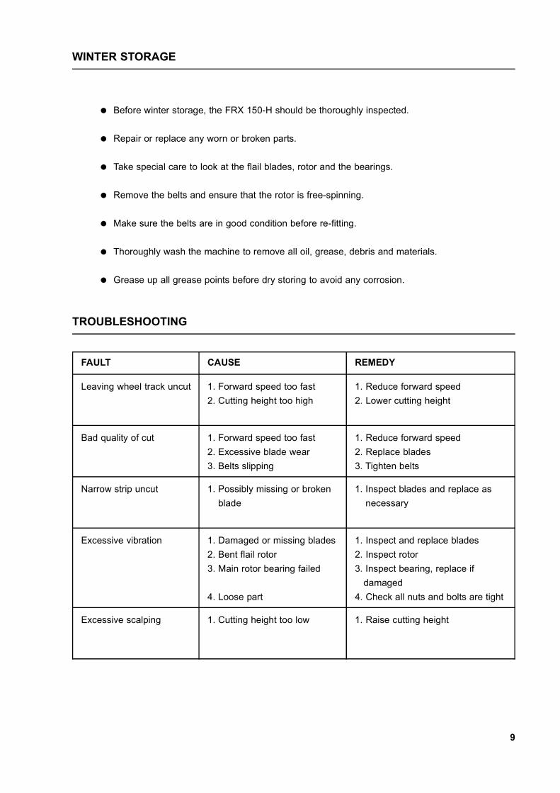
TROUBLESHOOTING
WINTER STORAGE
FAULT CAUSE REMEDY
Leaving wheel track uncut 1. Forward speed too fast2. Cutting height too high
1. Reduce forward speed2. Lower cutting height
Bad quality of cut 1. Forward speed too fast2. Excessive blade wear3. Belts slipping
1. Reduce forward speed2. Replace blades3. Tighten belts
Narrow strip uncut 1. Possibly missing or brokenblade
1. Inspect blades and replace asnecessary
Excessive vibration 1. Damaged or missing blades2. Bent flail rotor3. Main rotor bearing failed
4. Loose part
1. Inspect and replace blades2. Inspect rotor3. Inspect bearing, replace if
damaged4. Check all nuts and bolts are tight
Excessive scalping 1. Cutting height too low 1. Raise cutting height

10
PLATE 1
PARTS ILLUSTRATION - FRX150 BODY ASSEMBLY - PLATE 1

11
Item No. Part No. Description Qty. per Machine1 WX-30801 Bearing Guard Fixing Set 12 WX-16557 Bearing Guard 13 WX-5174 LH Side Skid 13 WX-5274 RH Side Skid 14 WX-1039 Eye Nut 15 WX-0227 Lynch Pin 26 WX-11703 Top Link Bolt 27 WX-33680 Linkage Spacer 28 WX-12458 Tractor Bracket 29 WX-31901 Nylon Pad Fastening Set 210 WX-8758 Nylon Pad 111 WX-0426 Top Link Pin 212 WX-30901 Botton Link Bolt 213 WX-31201 Skirt Fastening Set 114 WX-13978 Skirt 115 WX-15056 Adjuster Shaft Assembly 116 WX-31101 Roller Spigot Fastening Set 217 WX-3555 Roller Spigot 218 WX-8503 Skid Shoe Fastening Set 219 WX-4874 Skid Shoe 220 WX-8103 Skid Fastening Set 221 WX-24476 Front Flap - End Spacer 222 WX-24676 Front Flap 2223 WX-16377 Guard - Left Hand - FRX 150 124 WX-16177 Guard - Centre - FRX 150 125 WX-16477 Guard - Right Hand - FRX 150 126 WX-32780 Flap Bar FRX 150 127 WX-14958 Toro Link Arm - Left Hand 128 WX-15050 Toro Link Arm - Right Hand 129 WX-12728 Link Arm Bush 4
PARTS LIST - FRX150 BODY ASSEMBLY - PLATE 1

12
PLATE 2
PARTS ILLUSTRATION - FRX150 DRIVE ASSEMBLY - PLATE 2

13
Item No. Part No. Description Qty. per Machine1 WX-0547 Key 12 WX-12262 Taper Lock 12 WX-11062 Taper Lock (Toro) 13 WX-11962 Rotor Pulley 13 WX-10862 Rotor Pulley (Toro) 14 WX-7438 Bearing 25 WX-13977 Bearing Shield 26 WX-31601 Bearing Shield Fastening Set 27 WX-14466 Rotor Shaft 18 CYS-18593 Flail Bolt 329 WX-10170 Flail 3210 WX-16456 Hose Kit 111 WX-16356 Hydraulic Motor 112 WX-2047 Key 113 WX-18456 Motor Plate 114 WX-31801 Bolt 115 WX-16256 Motor Coupling 116 WX-5034 Belt 216 WX-6034 Belt (Toro) 217 WX-10962 Motor Pulley 118 WX-11862 Taper Lock 119 WX-2147 Key 1
PARTS LIST - FRX150 DRIVE ASSEMBLY - PLATE 2

14
PARTS ILLUSTRATION - FRX150 ROLLER ASSEMBLY - PLATE 3
PLATE 3
Item No. Part No. Description Qty. per Machine1 WX-3355 Roller 12 WX-3655 Roller End 23 WX-15703 Roller End Fastening Set 24 WX-3355A Roller Blanking Plug 25 WX-0838 Bearing 26 WX-3755 Roller Spacer 27 WX-4422 Circlip 28 WX-1450 Wheel Fork 29 WX-4652 Wheel 210 WX-16103 Wheel Fastening Set 211 WX-31880 Top Hat Bush 412 WX-16751 15mm Spacer 413 WX-16651 25mm Spacer 414 WX-0227 Linch Pin 2
PARTS LIST - FRX150 ROLLER ASSEMBLY - PLATE 3

15
MODEL FRX 150-H
Working Width: 1.5m
Overall Width: 1735
Overall Height: 500
Overall Length: 1090
Tyre Pressures: Solid Tyres
Weight Approximately: 230kg
SPECIFICATION

16
The undersigned personnel have been trained in the safe use of this Wessex Proline FRX 150-H andhave understood the contents of the Operator’s Manual.
SAFETY TRAINING INDUCTION
OPERATOR INSTRUCTOR/TRAINERDate Name Signature Name Signature

17
DAILY INSPECTION RECORD
OPERATOR’S NAME
DATE OFINSPECTION
HOURS
Flai
l Rot
or, r
emov
e ta
ngle
d ob
ject
s
Insp
ect c
ondi
tion
of F
lail
Blad
es/B
rush
es
All b
olts
and
nut
s, re
-tigh
ten
if re
q’d.
Gre
ase
Rot
or B
earin
gs
Gre
ase
Rol
ler B
earin
gs
Gre
ase
Whe
el C
asto
rs
Gre
ase
Whe
el B
earin
gs
Insp
ect T
yres
Insp
ect c
ondi
tion
of B
elts
Insp
ect t
ensi
on o
f Bel
ts

FRX 150-H
FLAIL MOWER
AUGUST 2013

NOTES

Wessex InternationalCharlton House, Caxton Close, East Portway Industrial Estate, Andover Hampshire. SP10 3QN
Telephone: 01264 345870 Fax 01264 345880e-mail: [email protected]
www.wessexintl.com