Embed Size (px)
Citation preview

OPERATION MANUAL

© Aixro GmbH / Woelfle Engineering GmbH 1/23
1. INTRODUCTION
1.1. Foreword
We would like to thank you for purchasing your new Aixro XR50 4-stroke rotary karting en-gine. By doing so, you have helped set new standards for driving performance and environ-mental responsibility.
! But before getting started, it is imperative that you read and understand instructions and procedures outlined in this operator manual!
You will obtain important safety advice and information about the correct installation, first launch and service of the engine. We wish you lots of fun! Aixro GmbH Woelfle Engineering GmbH Münsterstraße 44 Randstraße 109 52076 Aachen 47804 Krefeld Germany Germany (production) (distribution) www.aixro.de www.woelfle-engineering.com

© Aixro GmbH / Woelfle Engineering GmbH 2/23
1.2. General Safety Instructions
! The XR50 is one of the fastest karting engines available, and it might take some get-ting used to. Please remember to be safe, brake early, and never drive faster than you can control.
! The XR50 is made exclusively for kart racing. Using the engine in other applications is strictly prohibited without our express written consent. Race the XR50 on designated karting tracks only, so you never run the engine at full throttle for more than 10 con-secutive seconds.
! The exhaust can become very hot, over 1000°C! Avoid any contact when hot.
! Always use a kart with front and rear brakes.
! Always keep your kart and engine in a good, clean condition. This helps detect defects earlier and avoid dangerous accidents.
! You will find further (safety) advice in this manual, marked by “!”. Please read each of these tips carefully. If you have any questions, please contact your dealer, our Ameri-can importer RENNtech or us BEFORE you run the engine.
1.3. Development Stage
The operation manual is based on the state of knowledge at the time of publication. It was produced to best knowledge, however excluding any liability. The specifications may deviate from the actual performance due to production-related and external conditions. The information presented in this manual is subject to change without notice.
1.4. Copyright, circulation, date of issue
All rights reserved. The circulation or duplication of this document, even in extracts, is not permitted without ap-proval by Aixro GmbH or Woelfle Engineering GmbH. Title: Aixro XR50 Operation Manual Edition 4.6 Aachen/Krefeld: June 2011

© Aixro GmbH / Woelfle Engineering GmbH 3/23
2. TABLE OF CONTENTS
1. INTRODUCTION .............................................................................................................. 1 1.1. Foreword ................................................................................................................... 1 1.2. General Safety Instructions ........................................................................................ 2 1.3. Development Stage ................................................................................................... 2 1.4. Copyright, circulation, date of issue ........................................................................... 2
2. TABLE OF CONTENTS .................................................................................................... 3 3. ABOUT THE XR50 ........................................................................................................... 4 4. ASSEMBLY ...................................................................................................................... 5
4.1. Cooling System.......................................................................................................... 5 4.2. Engine Mounting and Chain Tension ......................................................................... 5 4.3. Carburettor / Fuel Supply ........................................................................................... 6 4.4. Throttle Cable ............................................................................................................ 7 4.5. Exhaust ..................................................................................................................... 7 4.6. Electrics ..................................................................................................................... 8 4.7. Data Acquisition ....................................................................................................... 10
5. FIRST LAUNCH .............................................................................................................. 11 5.1. Water ....................................................................................................................... 11 5.2. Fuel ......................................................................................................................... 11 5.3. Refuel / System Fill .................................................................................................. 11 5.4. Control ..................................................................................................................... 11 5.5. Start Preparation ...................................................................................................... 11 5.6. Engine Start / Test Run ............................................................................................ 12
6. OPERATION .................................................................................................................. 13 6.1. Preparation / Control ................................................................................................ 13 6.2. Starting / Heating Up On Track ................................................................................ 13 6.3. Driving ..................................................................................................................... 14 6.4. Shut Down ............................................................................................................... 15 6.5. Transportation ......................................................................................................... 15
7. SERVICE AND MAINTENANCE ..................................................................................... 16 7.1. Clutch Bearings / Drive Sprocket ............................................................................. 16 7.2. Friction Discs / Clutch Plates ................................................................................... 17 7.3. Air Filter Red Filter for Aixro and Dell’Orto Carburettors ........................................... 17
8. TROUBLESHOOTING .................................................................................................... 18 8.1. Engine Dropout ........................................................................................................ 18 8.2. Engine Stutters ........................................................................................................ 18 8.3. Backfire Under Braking ............................................................................................ 18 8.4. No Engine Start ....................................................................................................... 18 8.5. Dripping Carburettor / Overflow ............................................................................... 19 8.6. Engine Suddenly Lean ............................................................................................. 19
9. TUNING .......................................................................................................................... 20 9.1. Driving in Rain ......................................................................................................... 20 9.2. Clutch Adjustment .................................................................................................... 20 9.3. Carburettor Adjustment ............................................................................................ 20
10. TECHNICAL SPECIFICATIONS ..................................................................................... 21 10.1. Engine Data ............................................................................................................. 21 10.2. Fastening Torque ..................................................................................................... 21 10.3. Operating Fluids ...................................................................................................... 21
11. WARRANTY / LIABILITY ................................................................................................ 22 11.1. Liability .................................................................................................................... 22 11.2. Warranty Grant ........................................................................................................ 22 11.3. Warranty Procedure ................................................................................................. 22

© Aixro GmbH / Woelfle Engineering GmbH 4/23
3. ABOUT THE XR50
The Aixro XR50 is a rotary engine based on the Wankel principle. Its main components are Rotor with seals (equivalent to the piston with rings of a reciprocating piston engine) Eccentric shaft (equivalent to the crankshaft) Housing, also called trochoid due to its oval-like epitrochoid shape side plates, closing the sides of the housing The engine is a 4-stroke suction engine. Its rotor has a triangular shape, and the edges of the rotor are in permanent contact with the trochoid through the apex seals. This creates three separate combustion chambers along the flanges of the rotor and allows three 4-stroke processes to run simultaneously. The rotor only rotates at 1/3 of the speed of the eccentric shaft, so with every rotation of the shaft a different combustion chamber passes the spark plug. The processes within the engine, especially the long timings, lead to favourable emissions, which can be as low as 1% of comparable 2-stroke engines and reach best 4-stroke level in the driving cycle. The engine can be operated with a catalytic converter. The XR50 uses a carburettor and fuel lubrication at a ratio of 50:1. Contrary to a two-stroke engine the oil burns without residues. To access the combustion chamber the fresh gases first flow though one side plate. Then they flow through the rotor and the eccentric shaft in axial direction to reach the opposing side plate. From there they access the combustion chamber. This cools and lubricates the rotor, main bearing and eccentric shaft. At approx. 5500rpm a vacuum-controlled butterfly valve opens a second channel of the split inlet port to allow additional gases to flow directly into the combustion chamber. These cold fresh gases lead to the enormous power of the XR50. The particular advantages of the XR50 are its lack of vibration due to balanced rotating masses, its very compact design, the extreme performance with a very flat torque curve, as well as very low emissions. In addition the service performance is enormous for a racing en-gine, and it has long times between overhauls.

© Aixro GmbH / Woelfle Engineering GmbH 5/23
4. ASSEMBLY
4.1. Cooling System
The XR50 uses a standard karting radiator and a conventional water pump, which is driven by the rear axle, as well as standard karting water hoses. 1. Place the engine on your kart without bolting it down. This makes it easier to access
the water connections. 2. Mount the radiator without strain (usually on the left side of the kart). The radiator
should be mounted vertically enough to allow sufficient air flow through the system. 3. Connect one water hose at the lower connection of the radiator and the centre connec-
tion of the water pump. 4. Connect the radial connection of the pump with the lower connection at the front of the
engine with another hose. 5. Connect a third hose at the water connection on the backside of the engine (next to the
exhaust manifold) and the top of the radiator. 6. Fasten all connections with proper hose clamps.
! Ensure that the hoses are positioned far enough away from the exhaust to avoid melt-ing or cooking, and secure them with tie wraps if necessary.
! Make sure that there are no kinks or sharp bends in the hoses, and that they do not touch any moving parts or the ground.
! Note the rotation direction of the water pump.
4.2. Engine Mounting and Chain Tension
The XR50 is supplied with standard engine mounts, which fit most karts (Ø32mm x 92mm). Engine mounts for different tube distances or diameters are available upon request. Only use highest-quality chains and one-piece sprockets, type 428.
! Be sure that your engine mounts and clamps have the right dimensions. Otherwise you may damage your kart and the engine.
1. Install the engine mounts if they are not yet assembled to the engine (usually ship in-stalled; 4 countersunk screws M8x25 at 26Nm).
2. Remove the clutch cover (4 Allen screws – 1x M6x20, 3x M6x10 – note the positions of the screws), and mount the engine on the chassis.
3. Choose a suitable sprocket for your race track, and bolt it to the sprocket carrier. 4. Attach the engine to the kart with matching engine clamps. 5. Adjust the alignment between the front (clutch) and rear sprocket by moving the
sprocket carrier. Use a straight edge or alignment checking device as your guide. 6. Generally the engine should be positioned as close as possible to the rear axle to
achieve a short chain length. Therefore release the engine clamps again, (if applicable) screw the engine support screw, which is attached to the chassis, as far to the rear axle as possible, and put a preferably short chain around the sprockets.
7. Position the engine, so the chain has approx. 5mm “slack”, and tighten the engine clamps.
8. After tightening the clamps the chain tension should be checked at different positions of the rear axle. The chain must not be completely tight, but has to remain movable.
9. Now (if applicable) tighten the engine support screw, and re-attach the clutch cover 10. Install a standard chain guard (splash guard for the chain lubricant).
! Over-tightening the chain and worn components can build up heat. This significantly reduces the life expectancy of the clutch, especially the friction discs and the clutch bearing.
! A too loose or too long chain (chain slack >10mm) can also wear components.
! O-ring chains only run smoothly in use. Until an O-ring chain heats up, the load on the clutch is higher. Therefore never use an O-ring chain with a 10T drive sprocket.

© Aixro GmbH / Woelfle Engineering GmbH 6/23
! Never use a chain lock. The chain must be riveted.
! Do not use a gear ratio shorter than 11:53. A shorter gear ratio will not make you faster, but it will still increase the load on the engine and the tyre wear.
If you know the transmission ratio of a Rotax Max 2-stroke engine with a 12T sprocket, you can use it as a guideline. Divide the number of teeth of the rear sprocket by 1.75, and you have a first idea of the sprocket you need in combination with the standard 11T sprocket of the XR50. e.g. RMax: 12/79 79:1,75 ≈ 45 XR50: 11/45
If the chain is assembled, the chain alignment can be controlled by checking the position of the chain on the sprocket. In every position of the sprocket the chain must have slight space to the sprocket on both sides. This also ensures that the sprocket is not warped.
4.3. Carburettor / Fuel Supply
The fuel tank should have two connectors. One connector needs to have a line on the back-side, which leads to the bottom of the tank (a standard design for karting fuel tanks), while the other one must not have a tube on the backside. If the fuel tank should have a third con-nection, it should be blocked off or connected to a separate line, which has an open end se-cured above the level of the overflow tank. The overflow tank itself must be open to allow decompression and attached above the fuel tank, for example on one of the Nassau Panel brackets. 1. Slide the rubber carburettor connector over the inlet manifold, so it snaps into the grove
of the manifold, and attach it with a hose clamp. 2. Push the carburettor into the connector, so it snaps as well, and attach it with another
hose clamp. 3. Connect the fuel tank connector, which has the line on the backside, with the front
brass connector of the fuel pump. 4. Cut this line and install an in-line fuel filter (making sure it is clear from moving parts
and the ground). 5. Connect the fuel pump with the carburettor. 6. Connect the fuel tank with the overflow tank. 7. Connect the line of the (black, round) vacuum actuator with the nozzle at the inlet of the
carburettor.
Since the beginning of 2010 we have started using a new rectangular fuel pump instead of the round Mikuni fuel pump. The advantage of this pump is that it has an internal pressure limiter. Therefore it is no longer necessary to install a return to the fuel tank, and the needle valve of the carburettor has better performance.
Note that the carburettors have now been adjusted to operate with the new fuel pump, so they may not necessarily work properly with the Mikuni pump.
! The fuel lines must be made from fuel-resistant rubber.
! Attach the fuel lines to your kart using tie wraps or tape, making sure they are not touching the exhaust, the engine, moving parts or the ground. Check that tie wraps cannot move in case the kart should hit the ground.
fuel
tank
fuel pump
overflow
tank
Bing
carburettor
open
overflow
pipes
in-line
fuel filter
pip
e fo
r 3
rd c
on
ne
cto
r
ambient air
vacuum
actuator
carburettor

© Aixro GmbH / Woelfle Engineering GmbH 7/23
! Ensure that the fuel lines are not restricted by the attachment (kinks or sharp bends), as this can damage the engine.
4.4. Throttle Cable
1. Loosen the nut of the elbow section at the top of the carburettor, so its direction can be adjusted.
2. Lay an external throttle cable from the elbow to the throttle cable adjuster of your kart and cut it to the correct length, so the throttle cable is not distorted (too long) or kinked (too short).
3. Check the ends of the external cable making sure they are round and have no sharp edges.
4. Pull the throttle cable through the external cable and the cable adjuster until it reaches the elbow section and the cable adjuster.
5. Align the elbow to the external cable and secure the position by re-tightening the nut on the carburettor.
6. Attach the outside throttle cable to your kart using tape or tie wraps, so that it is clear from any moving parts and the ground.
7. Attach the throttle cable to the throttle pedal using a (twin screw) cable clamp. 8. Check the adjustment of the throttle cable and the throttle pedal. At idle position the
cable must be slightly loose while the slide of the carburettor remains at its lowest posi-tion. At full throttle the carburettor inlet should be fully open, and the throttle pedal should reach the limit screw of the chassis.
9. Tighten down the throttle cable clamp, the counter nuts and the pedal limit screws. 10. Attach the air filter to the flange of the carburettor and secure it with a hose clamp. 11. Avoid leaving a long open end of throttle cable behind the cable clamp. If the open end
is longer than 30mm, you should secure it. If your front bumper bar has a hole, you can put the open end into the hole and attach it with tape. It is also possible to attach it to the throttle cable with some small tie wraps or a fuel line, which you put around the throttle cable before attaching it to the throttle pedal.
! Check the throttle cable for smooth operation. A sticking cable may result in injuries or engine damage.
! Check that tie wraps used to attach the throttle cable to the chassis will not move if the kart hits the ground. Otherwise the throttle cable can get stuck while driving. In case of doubt it is better to use tape.
4.5. Exhaust
The attachment of the exhaust is similar to direct drive 100cc or KF-engines. It is attached in an exhaust cradle and secured with springs. 1. Bolt the exhaust header to the engine with a gasket in between. Use 3 M8 nuts tight-
ened to 25Nm. 2. Attach the silencer to the header. Hold it horizontally and without tension. This is the
correct position of the exhaust if the chain tension (=engine position) is set correctly. 3. Adjust the exhaust cradle to suit the silencer position. 4. Lay the silencer in the cradle and attach it to the manifold using the springs provided. 5. Attach the exhaust to the cradle using standard exhaust springs.
! If the exhaust is not attached without strain or tension this may cause cracks of the exhaust or manifold. Therefore you should also check the exhaust attachment when you change the gearing or the position of the engine.
Depending on the design of the attachment it may be useful to use a thick plate with two holes as an adapter for the exhaust cradle. This allows adjusting the position of the cradle in driving direction. The height of the cradle can be adjusted with additional spacers.

© Aixro GmbH / Woelfle Engineering GmbH 8/23
If the exhaust is attached without strain or tension, the rubber underneath the cradle can be removed. If not, it should at least be replaced by a strong spring, as the rubber will not with-stand the heat from the exhaust.
If you should not have an exhaust gasket, you can just bolt the exhaust header directly to the engine.
4.6. Electrics
From 2011 The Aixro XR50 is equipped with a PVL ignition, which includes some additional features for onboard starting. Even when equipped with the onboard starter the engine will start easily with an external starter.
4.6.1. External Starter
To start the engine with an external starter, use a 22mm socket on the clutch nut. The clutch nut should be easily accessible through the bodywork, so the starter can be removed easily after starting the engine. 1. Connect the ignition wires as shown on the diagramme below.
2. Attach the CDI box. Typically the best position is on the back of the seat. The CDI box should not be too close to the engine or the exhaust.
3. Mount the stop button / kill switch, so it is easily visible for the driver. The steering wheel is the best location. If it should not be possible to attach the switch to the steer-ing wheel, you should drill a hole (Ø 15mm) in the Nassau Panel (within easy reach of the driver) and attach the switch there.
4. Cover the wires you do not need and attach them with cable ties. 5. Drill or cut a sufficiently wide (long) hole in the side pod, and deburr it. Keep in mind
that the engine position varies depending on the gearing and chain length.
! Make sure the wires cannot wear or make contact with the ground and open ends are protected. Otherwise it may happen that you cannot start or stop the engine.

© Aixro GmbH / Woelfle Engineering GmbH 9/23
4.6.2. Onboard Starter
If your engine is equipped with an onboard starter, you need a battery with a compatible bat-tery tray and cables. Use a maintenance-free (MF type) lead-acid battery (no gel) with min. 7,2Ah and temporary 100A. Though the ignition has an integrated charging function, make sure the battery is always charged sufficiently. 1. Connect the ignition wires as shown on the diagramme below.
2. Mount the battery in an appropriate position. 3. Run the cables along the chassis, securing them so they cannot wear or hit the ground.
Make sure the cables cannot make any electrical contact with the chassis. 4. Attach the CDI box. Typically the best position is on the back of the seat. The CDI box
should not be too close to the engine or the exhaust. 5. Mount the stop button / kill switch, so it is easily visible for the driver. The steering
wheel is the best location. If it should not be possible to attach the switch to the steer-ing wheel, you should drill a hole (Ø 15mm) in the Nassau Panel (within easy reach of the driver) and attach the switch there.
Use sufficiently big cables for the conductive circuit between battery, relay and starter motor (10mm² / AWG8). 1.5mm² / AWG16 cables are sufficient for the control circuits.
! A shortcut between the battery terminals can destroy the battery or cause explosion of the battery.
! To avoid short circuits during transportation you should always disconnect the posi-tive terminal (+) from the battery when you stop your kart.

© Aixro GmbH / Woelfle Engineering GmbH 10/23
4.7. Data Acquisition
While driving you should monitor and record different parameters. There are several good and very refined systems on the market nowadays, e.g. made by Alfano, AIM or Unipro. The most important parameters for the engine are:
4.7.1. Engine Speed
The maximum engine speed shows you whether you have chosen the correct transmission ratio. Your maximum engine speed should be just less than the maximum engine speed of 11000rpm. Also you should keep an eye on the idle speed and the speed, at which the clutch engages. 1. Mount the sensor to the ignition cable according to the manual of the manufacturer,
and attach the sensor and the ignition cable, so both cannot make contact with moving parts or the ground.
2. Though the XR50 is a 4-stroke engine, it ignites with every engine revolution like a 2-stroke engine. Therefore your system should be set to “2-stroke”.
4.7.2. Water Temperature
The water temperature provides information on the engine load and the radiator capacity. While you are driving, the temperature should be 65..75°C (150..170°F). The sensor should be mounted close to the engine in the hose, which connects the engine with the radiator. 1. Use an adapter suiting the sensor and the hose. 2. Cut the hose, which connects the upper engine connector with the radiator, close to the
engine. 3. Insert the adapter, and secure it with hose clamps. 4. Insert the sensor in the adapter and secure it. 5. Attach the sensor and the sensor cable, so both cannot make contact with moving
parts or the ground.
4.7.3. Main Bearing / Transfer Port Temperature
The temperature of the fuel-air-mixture in the transfer port of the side inlet provides the most valuable information about the engine, especially the main bearing. You will discover that the temperature increases with engine speed and quickly drops again under braking. This means you get very quick feedback on the engine load and the strain of the main bearing. Use a quickly responding temperature sensor (K-type) with a M5 thread, e.g. AIM M5 Ex-haust Gas Temperature (EGT) Sensor, Alfano A-278. 1. Ensure that the engine is absolutely clean in the area of the screw, which is located
next to the inlet manifold in the ignition side plate (engine housing). 2. Remove the screw. 3. Insert the sensor. Make sure the sensor the sensor protrudes the end of the thread by
approx. 10mm, and that the sensor locks the housing airtight. 4. Connect the sensor as described by the manufacturer. 5. Attach the sensor and the sensor cable, so both cannot make contact with moving
parts or the ground.
! Double-check that the position of the sensor is right. If it protrudes the thread much more than 10mm, it can make contact with the rotor. If it does not stick out far enough, you will not get feasible results.
! Make sure the attachment is airtight. If the engine can pull air from the sensor area, it will run too lean and can get damaged.

© Aixro GmbH / Woelfle Engineering GmbH 11/23
5. FIRST LAUNCH
5.1. Water
1. Remove the cap from the radiator, and fill the cooling system with water. 2. Turn the rear axle manually to remove air from the system. 3. Add water until the radiator is filled to the top and tighten the radiator cap.
! Make sure the system is watertight (especially the hose connections).
Distilled water and a low percentage aluminium-compatible antifreeze prevent corrosion, but adding antifreeze can be forbidden on some race tracks.
5.2. Fuel
Premium unleaded brand name pump fuel (ROZ 95) is recommended. Standard unleaded fuel (ROZ 91) can also be used without problems. The engine must be operated with a fuel-oil-mixture at a 50:1 ratio, i.e. 100ml per 5l (US: 2.56fl.oz per 1gal / UK: 3.2fl.oz per 1gal). Use pre-diluted fully synthetic 2-stroke racing oil.
We recommend only to use the oil Mobil 1 Racing 2T.
! If you use the wrong oil or mixing ratio, this can cause damage or total loss of the en-gine – even if damage is not immediately apparent.
! Ensure that fuel and oil are pre-mixed properly in a petrol can.
5.3. Refuel / System Fill
In order to protect the engine, you should never start or run the engine without sufficient fuel supply. Before starting the engine, the fuel tank should always be at least ¾ full, and all fuel lines should be full as well. 1. Fill the fuel tank with pre-mixed fuel. 2. Blow air into the overflow tank until the fuel line to the carburettor is completely full (a
few air bubbles will stay in the line – this is no problem).
! Make sure all fuel lines are properly secured and do not leak.
5.4. Control
! Double-check the assembly and the steps for first launch.
5.5. Start Preparation
The XR50 can be started with an external starter or an onboard-starter (if so equipped). Al-ways make sure the battery is fully charged.
! Normally the engine will start immediately. If it should not start right away, you should look for errors instead of trying again.
! Never run any starter for more than 5 seconds without interruption.
! When starting the engine with the external starter, make sure you pull the starter off the nut immediately after cranking. Otherwise the clutch nut and the clutch may un-screw.

© Aixro GmbH / Woelfle Engineering GmbH 12/23
5.6. Engine Start / Test Run
When testing the engine for the first time, you should let it idle briefly with the rear axle rotat-ing freely. Make sure the kart is secure, only use the throttle very carefully, and never play with the throttle (as some do to keep 2-stroke engines running). Always be prepared to switch off the engine.
! Without load the engine can accelerate much faster than a rev counter can record. At full throttle the engine can exceed 10000rpm within one (1) second.
! From 2008 all Aixro XR50 engines are equipped with a rev limiter. Still, the rev limit can be exceeded in case of a malfunction, especially if you run the engine at too high speed without load. This can lead to engine detonation (flying parts can cause serious injury).
1. Leave the throttle in idle position, or at a maximum very gently push the throttle pedal a short distance (NOT full throttle).
2. Do not play with the throttle. 3. Start the engine. 4. Let the engine idle for about 20 seconds. 5. Leave the throttle pedal in idle position. 6. Let the engine idle for about 10 seconds. 7. Push the red off-button. 8. Let the engine cool down. 9. The engine is now ready for operation.
! Never make any adjustments while the engine is running.
! The exhaust becomes very hot and can cause severe burns.
! If the engine should not switch off, pull the choke lever and/or cover the air filter with your hands to force it to shut off.

© Aixro GmbH / Woelfle Engineering GmbH 13/23
6. OPERATION
6.1. Preparation / Control
Check your kart thoroughly before starting the engine: 1. Are your kart and engine in a good condition without damage? 2. Do the front and rear brakes work perfectly? 3. Are the radiator and the cooling system still completely filled and leak proof? 4. Does the fuel contain the right oil in the right ratio? 5. Is the fuel tank at least ¾ full? 6. Are the fuel lines to the carburettor filled and in good condition? 7. Are the carburettor and the air filter attached properly? 8. Does the throttle cable operate smoothly and without sticking? 9. Does the throttle cable slightly slack in idle position? 10. Is the throttle cable tight in full throttle position? 11. Does the throttle pedal touch the limit screw in full throttle position? 12. Is the off-switch properly connected with the engine? 13. Is the off-switch cable in good condition? 14. Is the exhaust attached without strain or tension? 15. Is the exhaust attached properly? 16. Is the battery of the starter fully charged? 17. Does the gearing suit the race track? 18. Are the engine mounts tightened? 19. Are the sprockets and the chain in good condition? 20. Is the chain well-aligned? 21. Is the chain tension correct? 22. Is the chain lubricated? 23. Are the clutch bearings lubricated? 24. Are the friction discs in good condition? 25. Are the carriers of the friction discs in good condition? 26. Is the clutch cover attached properly?
6.2. Starting / Heating Up On Track
1. Apply the brakes. This is particularly important when using an external starter. 2. If the engine is already warm, you do not need the choke. Otherwise, start the engine
as described in the First Launch section. 3. Drive slowly to warm up the engine carefully. Increase the speed slowly.
! You should never start the engine for driving, unless a driver is sitting in the kart to operate the brakes and the off-switch.
! Do not run the engine above 8500rpm in the first hour of operation.

© Aixro GmbH / Woelfle Engineering GmbH 14/23
6.3. Driving
With the XR50 you will be quicker than most other karts on the track. Have fun, but be con-siderate of other drivers and never drive faster than your skills and experience allow. Try to develop a smooth driving style. Brake early, build momentum with high apex speeds, and accelerate early from corners. This is much quicker than braking and drifting hard.
! You will have to get used to the performance of the engine. Slow down if you feel that you do not have full control over your kart.
! Due to the higher speed you will have to brake earlier.
! Make sure you do not accelerate and brake at the same time and that you do not let the clutch slide, as this may overheat the clutch and wear the friction discs very quickly.
! Pay attention to the fuel level, and make sure you do not run out of fuel.
While driving, make sure you run the engine within the optimal operation parameters:
6.3.1. Engine Speed
From 2008 all XR50 are equipped with a rev limiter. Still you should adjust the transmission ratio to keep the maximum engine speed below 11000rpm.
! Make sure the rev limiter does not or hardly engage.
! If you have an earlier model of the XR50, have the ignition replaced to protect the en-gine from too high speed, as this can lead to engine detonation (flying parts can cause serious injury).
6.3.2. Water Temperature
After heating up the engine, the water temperature should be 65..75°C (150..170°F).
If the water temperature is too low, you can mask part of the radiator with tape. If it is too high, the radiator may have too little capacity, or there may be a problem.
! Do not run the engine with too high water temperature, as this may lead to engine damage.
! If you observe a strange water temperature (e.g. significantly lower than usual), the cooling system may have a leak. In such a case stop the engine immediately and check the cooling system when the engine has cooled down.
6.3.3. Main Bearing / Transfer Port Temperature
The transfer port temperature swings significantly while you are driving. It should never ex-ceed 140°C (285°F).
! If the temperature exceeds 140°C (285°F), stop the engine as soon as possible and check the engine or have it checked, as this indicates a bigger problem (e.g. housing leak, insufficient lubrication).
! Note that the maximum temperature is typically reached under braking after long straights. As you will not always have time to watch your data logger in this situation, also check the engine temperature after every session.
© Aixro GmbH / Woelfle Engineering GmbH 15/23
6.4. Shut Down
1. Take a slightly slower out-lap. 2. Switch the engine off as soon as you have reached the paddock. 3. Let the engine cool down. 4. To make sure the onboard-starter does not start the engine unintentionally, you should
disconnect the positive (+) terminal from the battery when you park your kart.
! The exhaust becomes very hot. Caution! It will cause severe burns!
! Before driving again, review the checklist to make sure that your kart is still in good condition and fully operational.
It is normal to see the water temperature increase after stopping the engine, because the wa-ter pump is not running any more, and the radiator is not cooled by any wind.
Lubricate the chain with chain lube immediately after driving. While still warm, the chain ab-sorbs lube more readily and lasts longer. Make sure to lube the chain links as well as the running surface of the chain.
The lifetime of a battery is greatly reduced when it is totally discharged. Charge the starter battery regularly – even if it is not empty.
6.5. Transportation
Fuel can sometimes escape from the carburettor or the fuel tank during transportation – es-pecially if the kart is transported vertically. Always empty the fuel tank and the float bowl of the carburettor before transportation.
! When removing parts like the carburettor or the exhaust from the engine, you should close all ports airtight.
© Aixro GmbH / Woelfle Engineering GmbH 16/23
7. SERVICE AND MAINTENANCE
Engine service is due once a year or every 50 hours of operation (whichever comes first). Have the engine serviced by an approved dealer, the American distributor RENNtech, or the Aixro factory to maintain warranty for the engine. A normal overhaul usually includes a check to make sure the engine components are still in good condition. Sometimes it may become necessary to replace bearings. Otherwise no fur-ther service is necessary, so the XR50 requires remarkably less maintenance than other karting engines. Under normal use the only parts requiring regular maintenance are the clutch, chain, and air filter. Keeping the engine clean and free from dirt and oil is considered part of a proper main-tenance routine. If you do not dare to maintain the clutch, or you do not have the proper tools, you should con-tact your dealer to ensure the work is done correctly.
! Always keep your kart and engine clean. This makes it easier to discover defects.
! Improper clutch assembly can damage the engine. In the worst case parts can even fly off the engine and cause serious injuries.
7.1. Clutch Bearings / Drive Sprocket
Depending on the wear of the clutch, it is necessary to grease the clutch bearings on a regu-lar basis. We recommend an interval of 1..2 hours of operation. Use high-temperature bear-ing grease and a (Aixro) clutch wrench. When disassembling the clutch, check the condition of the drive sprocket and replace it if necessary. 1. Remove the clutch cover and note the locations of the different screws. 2. Hold the clutch in place using the clutch wrench, and release the 22mm clutch nut. 3. Release the rear sprocket or the engine clamps, so the sprocket is not retained by the
chain when you pull it off. 4. Pull the clutch off the eccentric shaft. Be careful not to lose the small clutch key. 5. Lay the clutch aside with the drive sprocket facing upward. 6. Lift the sprocket off the clutch. It can now be replaced if necessary. 7. Grease the three-piece axial bearing (bearing in a cage with two washer discs). 8. Also grease the bearing in the sprocket and the running surface on the clutch. 9. Slide the sprocket back over the clutch. 10. Grease the eccentric shaft and slide the clutch onto the shaft. 11. Insert the clutch key into the keyway. It will only fit one way. 12. Hold the clutch in place using the clutch wrench, and tighten down the clutch nut. 13. Re-attach the clutch cover. 14. Re-attach the rear sprocket, or bolt down the engine clamps. 15. Check the chain tension in different positions of the rear axle.
Once you have a feeling for the appearance of a worn drive sprocket, you do not need to re-lease the rear sprocket or the engine clamps, unless you want to replace the sprocket.
© Aixro GmbH / Woelfle Engineering GmbH 17/23
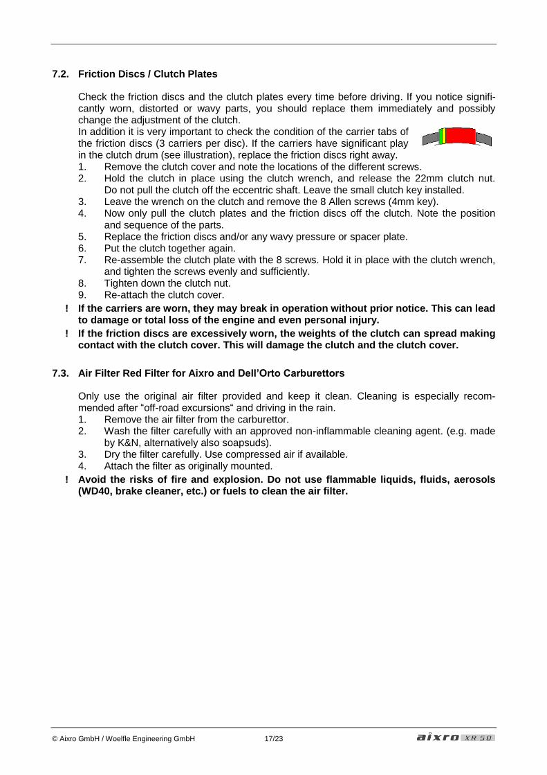
7.2. Friction Discs / Clutch Plates
Check the friction discs and the clutch plates every time before driving. If you notice signifi-cantly worn, distorted or wavy parts, you should replace them immediately and possibly change the adjustment of the clutch. In addition it is very important to check the condition of the carrier tabs of the friction discs (3 carriers per disc). If the carriers have significant play in the clutch drum (see illustration), replace the friction discs right away. 1. Remove the clutch cover and note the locations of the different screws. 2. Hold the clutch in place using the clutch wrench, and release the 22mm clutch nut.
Do not pull the clutch off the eccentric shaft. Leave the small clutch key installed. 3. Leave the wrench on the clutch and remove the 8 Allen screws (4mm key). 4. Now only pull the clutch plates and the friction discs off the clutch. Note the position
and sequence of the parts. 5. Replace the friction discs and/or any wavy pressure or spacer plate. 6. Put the clutch together again. 7. Re-assemble the clutch plate with the 8 screws. Hold it in place with the clutch wrench,
and tighten the screws evenly and sufficiently. 8. Tighten down the clutch nut. 9. Re-attach the clutch cover.
! If the carriers are worn, they may break in operation without prior notice. This can lead to damage or total loss of the engine and even personal injury.
! If the friction discs are excessively worn, the weights of the clutch can spread making contact with the clutch cover. This will damage the clutch and the clutch cover.
7.3. Air Filter Red Filter for Aixro and Dell’Orto Carburettors
Only use the original air filter provided and keep it clean. Cleaning is especially recom-mended after “off-road excursions“ and driving in the rain. 1. Remove the air filter from the carburettor. 2. Wash the filter carefully with an approved non-inflammable cleaning agent. (e.g. made
by K&N, alternatively also soapsuds). 3. Dry the filter carefully. Use compressed air if available. 4. Attach the filter as originally mounted.
! Avoid the risks of fire and explosion. Do not use flammable liquids, fluids, aerosols (WD40, brake cleaner, etc.) or fuels to clean the air filter.

© Aixro GmbH / Woelfle Engineering GmbH 18/23
8. TROUBLESHOOTING
Problems can also occur with the XR50. Some can be resolved at the track with basic knowledge, while other problems should only be handled by an expert. Generally you should only do work you are comfortable with. If you feel overwhelmed or unsure, your dealer will be available to help you or to contact aixro for support.
! If the engine suddenly runs differently, there will be a reason for this, so don’t just keep going. Try to find the problem and solve it. While doing so, keep a particularly close eye on the water and bearing temperature. If you should be uncertain, you should rather contact your dealer directly.
8.1. Engine Dropout
The root cause for dropouts is normally an issue of fuel supply. If the carburettor does not get enough fuel, a fuel line may be blocked, or the depression line between the engine and the fuel pump can be damaged. It might also just be an empty fuel tank that causes the problem. If dropouts occur in fast or tight turns, it can be helpful to turn the carburettor, so the float bowl points to the outside (up to 20° from vertical position). Another option is to modify the float level, so the needle valve in the carburettor closes at a higher fuel level.
8.2. Engine Stutters
Note that the engine tends to run rich with a dirty air filter. If the engine does not run smoothly, or if it stutters at 4000..6000rpm, check the air filter and clean it if necessary. If the vent pipes of the carburettor have sharp bends, the carburettor function may be con-stricted as well. Another root cause can be a malfunction of the ignition. If the ignition spark loses its inten-sity, the combustion is delayed. The carburettor setting then feels rich, even though this is not the problem.
! When the engine suddenly starts to stutter, do not try to correct this condition with a leaner carburettor jetting as this will only hide the root cause and lead to insufficient engine lubrication.
! If you experience stuttering, please observe the bearing temperature carefully, as it may also be a symptom of an overheated main bearing.
8.3. Backfire Under Braking
If the engine is too lean at bottom end, it will make a “bang” sound under braking. In this case you should lift the carburettor’s jet needle by putting the securing clip one position down.
8.4. No Engine Start
If the engine will not start despite a fully charged starter battery, clean air filter and sufficient fuel supply, the spark plug may be the problem (although this is unlikely). To check, remove the spark plug from the engine. If it is wet and oily with excessive soot, you should replace it and properly dispose the old spark plug.
! Only use the original Denso U22ETR spark plug. Failure to do so can result in engine damage, as a too long spark plug could collide with the apex seals.
If the engine should not start, the reason could also be the off-switch. Check the switch and wiring for damage.

© Aixro GmbH / Woelfle Engineering GmbH 19/23
8.5. Dripping Carburettor / Overflow
If the carburettor loses fuel at the top of the float bowl, the gasket of the float bowl may be damaged. In this case remove the float bowl and replace the gasket. Fuel can also leak from the overflow lines. If these are leaking, they should also be replaced. If fuel should especially escape through the overflow lines in curves, the float level may be too high, so the fuel supply to the carburettor is blocked too late. In this case reduce the float level.
8.6. Engine Suddenly Lean
! If the engine suddenly develops a lean condition, or the idle speed is higher than nor-mal, you should reduce the engine speed immediately and stop the engine as soon as possible. Failure to do so could lead to excessive wear and engine damage from lack of lubrication.
The most simple cause for this issue is a damage of the rubber carburettor connection. Check it thoroughly for cracks, and replace it if any damage is visible.
! If you notice a crack or emersion of oil in the area of the eccentric shaft or the engine housing, you should have the engine checked by an expert.

© Aixro GmbH / Woelfle Engineering GmbH 20/23
9. TUNING
9.1. Driving in Rain
No changes to the engine are necessary to run it in wet conditions. You should just cover the air filter, so it does not take up too much water. Also please note that the clutch can overheat more easily.
9.2. Clutch Adjustment
The clutch is a centrifugal racing clutch with 6 weight levers. As the engine speed increases, the levers spread and increase the force on the friction discs until the clutch drags and then fully engages. In its standard configuration the clutch is set to quick engagement at low en-gine speed. To ensure a long clutch life, please just leave the clutch as is, i.e. with screws in all 6 balance weights and the pre-load screws set to a height of 9mm.
! Modifications of the clutch setting can lead to very quick overheating of the clutch.
! Note that no warranty can be claimed for an overheated clutch. This is even the case when the clutch is run in its standard setting, because overheating can be caused by driving mistakes (driving constantly at low speed, accelerating and braking at the same time, etc.).
9.3. Carburettor Adjustment
It is not a problem to run the Aixro XR50 with a rich jetting, and standard jetting of the carbu-rettor works well under most conditions. If you should want to try jetting modifications, you should be very careful. Below you can see the standard settings of the carburettors available:
9.3.1. Aixro YSN PWK30
main jet: 145 (135 with power jet version) needle: PW30, clip in highest or second-highest position vent screw: opened 1½ turn slide screw: 3 turns / 2mm from BDC of the slide air filter: Aixro red
9.3.2. Dell’Orto VHSH30W
main jet: type 6413 M6 158 idle jet: type 12995 M5 55 choke jet: 45 needle: K27 needle jet: DQ 265 vent screw: opened ¼..½ turn slide screw: 2½ turn from BDC of the slide air filter: Aixro red
! A lean condition can lead to total loss of the engine.
! Never use an air duct to the inlet or a karting airbox around the carburettor filter. This can even lead to engine damage if the jetting is on the rich side, because the engine may run too lean at high engine speed.

© Aixro GmbH / Woelfle Engineering GmbH 21/23
10. TECHNICAL SPECIFICATIONS
10.1. Engine Data
type: 4-stroke single rotor rotary engine power: 33 kW at 8750rpm weight: ca. 17 kg torque: 39 Nm at 7500rpm chamber volume: 294 ccm max. rpm: 11000rpm ignition: magnet CDI ignition with variable ignition timing clutch: 2-disc dry centrifugal clutch drive: ½ in chain type 428 spark plug: Denso U22ETR starter (optional) 12V / 0,4kW battery (optional) min. 12V / 7,2Ah / temporary 100A / type MF (=maintenance free)
10.2. Fastening Torque
clutch nut: M14x1.5 30Nm spark plug: M10x1 12Nm exhaust nuts: M8 22Nm engine mounts: countersunk M8x25 26Nm
10.3. Operating Fluids
fuel: min. premium unleaded ROZ 95 approved oil: Mobil 1 Racing 2T mixing ratio: 50:1 (fuel:oil) coolant: water (recommendation: distilled water with 3 % antifreeze)

© Aixro GmbH / Woelfle Engineering GmbH 22/23
11. WARRANTY / LIABILITY
11.1. Liability
The Aixro XR50 motor may only be operated at the user’s own and unlimited risk. This in-cludes personal and material damage, injury, loss of wages, etc.
11.2. Warranty Grant
Only aixro GmbH is authorized to covenant warranty grants. Aixro guarantees the faultless function of the engine if it is used and maintained properly as described in this manual. Warranty claims can only be made if the sealing of the engine is not damaged and the en-gine has been overhauled in an interval of 50 hours of operation or annually (whichever ap-plies earlier) by an approved dealer. It is the duty of the customer to provide evidence for the date of purchase, the hours of op-eration, proper maintenance, proper adherence to overhaul intervals and proper use of the engine.
11.3. Warranty Procedure
In case of a warranty claim the claim should please be made in writing, if possible with pic-ture documentation, to the e-mail address [email protected]. Upon request the complete engine must then be made available through the dealer, RENN-tech, or directly to Aixro GmbH. After inspection of the engine, defective parts (as determined by Aixro GmbH) will be repaired or replaced if a warranty claim is applies. The engine can be assembled by a dealer, RENNtech or in the Aixro factory. If assembled in the factory, an assembly cost of € 100 will be invoiced. The engine will be shipped at the cus-tomer’s expense. Parts replaced free of charge remain the property of aixro GmbH.


![refrigerant for Industrial Refrigeration - OMNICO Engineeringomnico-engineering.com/Danfoss-CO2_Refrigerant_for_Industrial... · essu re [b ar] Pressure [psi] [bar] 14500 1000 145](https://img.pdfslide.us/doc/110x75/5aaea61e7f8b9a190d8c61c5/refrigerant-for-industrial-refrigeration-omnico-engineeringomnico-re-b-ar-pressure.jpg)
![Oblogka [Converted 2012] - Agbor-Engineeringagbor-engineering.com/files/agbor_ru/Engineering-rus-2015_web.pdf · цеха, цех механической обработки, складские](https://img.pdfslide.us/doc/110x75/5f88a20b9663e66fdf0967cd/oblogka-converted-2012-agbor-engineeringagbor-.jpg)