Embed Size (px)
Citation preview

Clearstone Technologies Inc. Page 0 of 33 www.clearstonetech.com
4 June 2012 CF2000/CT2000 Operation Manual
Operation Manual
Controller/Power Supply CF2000 and CT2000
5301 Humboldt Ave. S. Minneapolis, MN 55419 USA
Tel: +1-612-824-4846 Email: [email protected]
Website: www.clearstonetech.com
Clearstone Technologies Inc.625 St. Louis St., Unit 35Hopkins, MN 55343, USA
Email: [email protected] Web: www.clearstonetech.com
Phone: (612) 824-4846

Clearstone Technologies Inc. Page 1 of 33 www.clearstonetech.com
4 June 2012 CF2000/CT2000 Operation Manual
Introduction This is the Operation Manual of the CF2000 and CT2000 Controller/Power Supply. Part I outlines basic operating procedures, Part II covers remote operation, and Part III discusses safety concerns. Outline
Topic Page Parts List CF2000/CT2000 systems 2
Part I: Standard Operation Attachment of LED Head to Controller 3 Back Panel 4 Turning on Controller/Power Supply 4 Front Panel Functions 5 Basic Operation 6 Performance Monitor for CF2000-PM 7 Capabilities 8 Safety 8 Disclaimer 8 Cleaning 8 Warrantee 8 Compatible LED Heads 9 Accessories 9 Part II: Remote Operation Installation of Drivers on PC 10 Remote Access Demo 11 Command Descriptions 19 Resetting to the Factory State 23 Installing RS232 Adaptor Option 24 Footswitch Input Circuit 27 Part III: Safety Guidelines and Information 28 EC Declaration of Conformity 33
The most recent version of the Operation Manual may be found at the Clearstone website: www.clearstonetech.com Front Cover Left: Photograph of CF2000 Front Cover Right: Photograph of CT2000
Clearstone Technologies Inc. Page 2 of 33 www.clearstonetech.com
4 June 2012 CF2000/CT2000 Operation Manual
Parts List
Parts List for CF2000 System Box 1: CF2000 Item 1: CF2000 Box 2: CF2000 Accessory kit Item 1: 8 inch vertical post Item 2: 6 inch LED Head mounting arm Item 3: Right angle clamp Item 4: Footswitch with cord Item 5: AC power cord Item 6: UV protective goggles Item 7: CF2000 Setup CD Item 8: USB cable, 2 meter Item 9: Operation Manual Part Lists for CT2000 System Box 1: CT2000 Item 1: CT2000 Box 2: CT2000 Accessory kit Item 1: Footswitch with cord Item 2: AC power cord Item 3: UV protective goggles Item 4: CT2000 Setup CD Item 5: USB cable, 2 meter Item 6: Operation Manual (UV or Visible Wavelength LED heads sold separately)
If your boxes did not contain the listed items, contact Clearstone Technologies, Inc.
Clearstone Technologies Inc. Page 3 of 33 www.clearstonetech.com
4 June 2012 CF2000/CT2000 Operation Manual
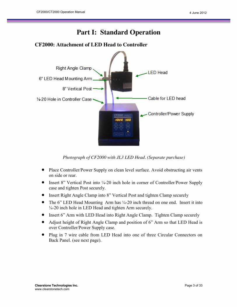
Part I: Standard Operation CF2000: Attachment of LED Head to Controller Photograph of CF2000 with JL3 LED Head. (Separate purchase)
x Place Controller/Power Supply on clean level surface. Avoid obstructing air vents on side or rear.
x Insert 8” Vertical Post into ¼-20 inch hole in corner of Controller/Power Supply case and tighten Post securely.
x Insert Right Angle Clamp into 8” Vertical Post and tighten Clamp securely x The 6” LED Head Mounting Arm has ¼-20 inch thread on one end. Insert it into ¼-20 inch hole in LED Head and tighten Arm securely.
x Insert 6” Arm with LED Head into Right Angle Clamp. Tighten Clamp securely x Adjust height of Right Angle Clamp and position of 6” Arm so that LED Head is
over Controller/Power Supply case. x Plug in 7 wire cable from LED Head into one of three Circular Connectors on
Back Panel. (see next page).
Clearstone Technologies Inc. Page 4 of 33 www.clearstonetech.com
4 June 2012 CF2000/CT2000 Operation Manual
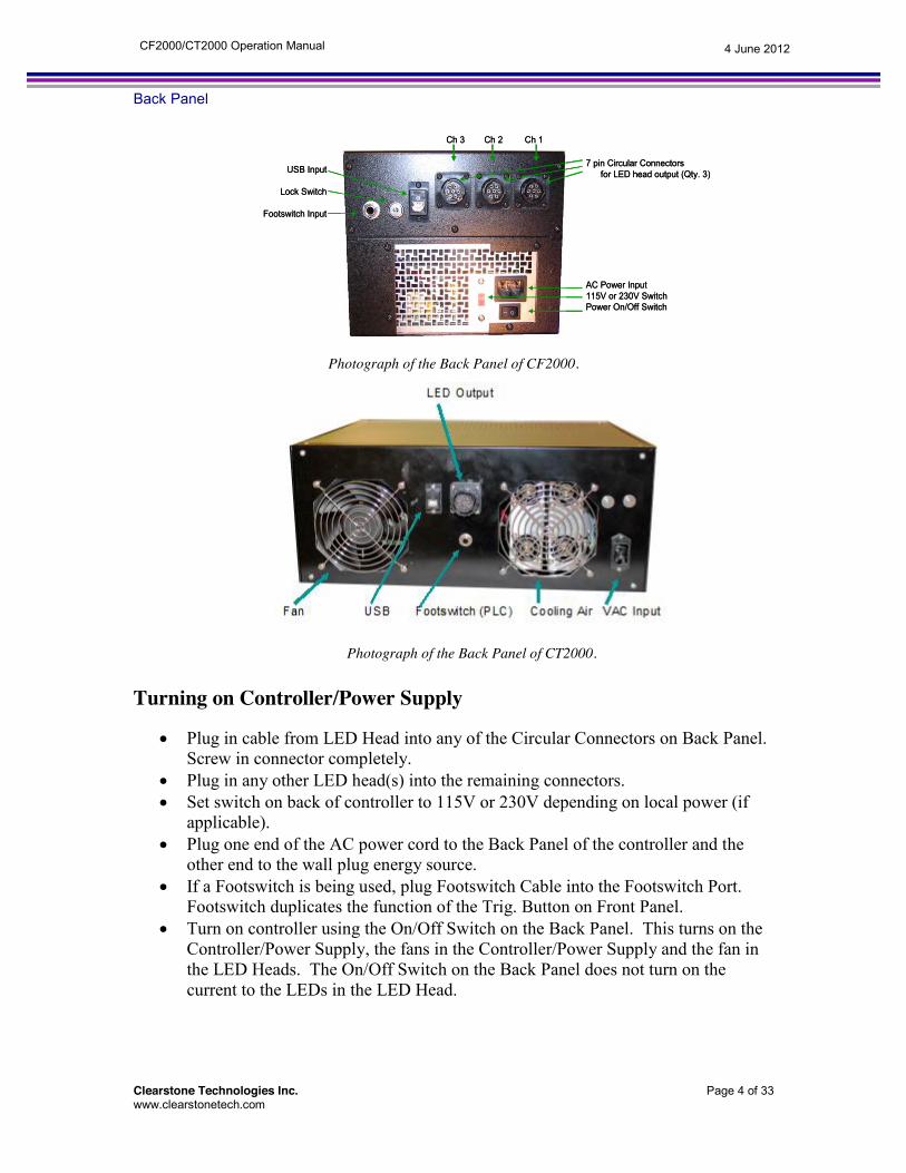
Back Panel
Photograph of the Back Panel of CF2000.
Photograph of the Back Panel of CT2000. Turning on Controller/Power Supply
x Plug in cable from LED Head into any of the Circular Connectors on Back Panel. Screw in connector completely.
x Plug in any other LED head(s) into the remaining connectors. x Set switch on back of controller to 115V or 230V depending on local power (if
applicable). x Plug one end of the AC power cord to the Back Panel of the controller and the
other end to the wall plug energy source. x If a Footswitch is being used, plug Footswitch Cable into the Footswitch Port.
Footswitch duplicates the function of the Trig. Button on Front Panel. x Turn on controller using the On/Off Switch on the Back Panel. This turns on the
Controller/Power Supply, the fans in the Controller/Power Supply and the fan in the LED Heads. The On/Off Switch on the Back Panel does not turn on the current to the LEDs in the LED Head.
7 pin Circular Connectors for LED head output (Qty. 3)
AC Power Input115V or 230V SwitchPower On/Off Switch
USB Input
Lock Switch
Footswitch Input
Ch 3 Ch 2 Ch 1
7 pin Circular Connectors for LED head output (Qty. 3)
AC Power Input115V or 230V SwitchPower On/Off Switch
USB Input
Lock Switch
Footswitch Input
Ch 3 Ch 2 Ch 1

Clearstone Technologies Inc. Page 5 of 33 www.clearstonetech.com
4 June 2012 CF2000/CT2000 Operation Manual
Front Panel Functions Photograph of Front Panel of CF2000.
Emission Indicator & Button
x The square button on the bottom right label “Trig.” is pushed to start the emission. The light above it becomes lit when the LED Head is emitting.
x When the “Trig” button is pushed during emission, the exposure is cancelled and the LEDs are turned off.
x In Auto mode, the emission will stop and the light turns off upon completion of emission duration.
Power Up/Down Button x The Power Up and Power Down buttons will increase or decrease the emission strength. x The display above it shows the power level setting, from 0 to 100% of maximum. x The control is “wrap around”, i.e.,
o If power level is 100% and Up Button is pushed, power level goes to 0% o If power level is 0% and Down Button is pushed, power level goes to 100%
Audio Indicator & Button x Rectangular button in center bottom is pushed to go from Audio Mode to Non - Audio Mode
and vice versa. x In Audio Mode, light above it becomes lit, a short tone sounds every second when the LED is
emitting, and a long tone sounds when the emission is completed. x In Non-Audio Mode, the tone is deactivated.
Auto Indicator & Button x Rectangular button on left bottom is pushed to go from Auto Mode to Manual (not Auto)
Mode and vice versa. x In Auto Mode, light above the button is lit. Before triggering the exposure, the Time Display
shows the set exposure duration. During an exposure, the Time Display shows the remaining time on the exposure.
x In Manual Mode, light above the button is not lit. The Time Display shows zero when the LED head is not emitting. During an exposure, the Time Display shows the increasing exposure duration.
Power Setting Display (%)
Power Up Button
Power Down Button
Emission Indicator
Emission Button
Audio Indicator
Audio Button
Time Display (Min:Sec)
Minute Up Second Up
Minute Down Second Down
Auto Indicator
Auto Button

Clearstone Technologies Inc. Page 6 of 33 www.clearstonetech.com
4 June 2012 CF2000/CT2000 Operation Manual
Basic Operation Set Up
x Attach LED Head - Page 3 x Turn on Controller/Power Supply -Page 4
Default Values
x When On/Off Switch in Back Panel is turned on, the following Default Values appears: o In Auto Mode, Light on o In Audio Mode, Light on o Trig., Light Off o Power Level, 10% o Exposure; 10 sec
Set Emission Power Level
x Use Power Up/Down Buttons to set Power Level; 0 to 100%. Power Level 1-4% is not available on the CT2000.
x Power Setting Display: indicates Power Level in Percentage Manual (not-Auto) Mode
x An unlit indicator above the Auto button indicates, the system is in Automatic Mode x Push the Auto button to toggles the system between Manual and Auto mode. x Time Display: 0 x Push Trig. Button to start emission, Light above Trig. Buttons lights up x Time Display: tracks the exposure duration. x Push Trig. Button to stop emission, Light above Trig. Buttons unlit x Time Display: 0
Automatic Mode
x A lit indicator above Auto button indicates, the system is in Automatic Mode x If Light above Auto unlit, push Auto Button to enter Automatic Mode
Set Emission Time
o Buttons: select Minutes up to 59 min o Buttons: select Seconds up to 59 sec o Time Display: Emission Duration Time
Start Emission
o Push Trig., turns on emission o Indicator Light above Trig. lights up o Time Display: remaining Emission Time
Emission Stops Automatically
o Emission stops when Emission Duration Time is reached o Indicator Light above Trig. unlit o Time Display: indicates Emission Duration Time for next exposure
Ready for Next Exposure
o Go to “Start Emission”

Clearstone Technologies Inc. Page 7 of 33 www.clearstonetech.com
4 June 2012 CF2000/CT2000 Operation Manual
To Leave Auto Mode x Push Auto Button if in Auto Mode, Indicator Light above Auto unlit x Now in Manual Mode, ready for continuous emission
Audio Mode
x A lit indicator above the Audio button indicates an active buzzer. x An unlit indicator above the Audio button indicates a muted buzzer. x Pushing the Audio button toggles the buzzer between active/muted.
Footswitch
x Footswitch and cord supplied with CF1000, CF2000 and CT2000 x Footswitch duplicates Trig. Button function x Footswitch connector on Back Panel
Key Lock
x Purpose: prevent inadvertent or unauthorized change in Power Level setting or Emission Duration Time
x To lock in settings, insert Key in Back Panel and turn clockwise quarter turn. x To unlock, turn key back quarter turn
Performance Monitor for CF2000-PM
Prototype LED Performance Monitor circuits are available by special order in some of the UV LED heads. A prototype version of CF2000, designated as CF2000-PM, has been built to work with these LED Heads. The purpose of the Performance Monitor is to detect an LED that has become inoperable. The Performance Monitor functions when the Power Level is set higher than 25%. If an LED fault is detected, the LED light emission is halted, the status LEDs on the LED Head will blink and the audio indicator on CF2000-PM will sound continuously. This will alert the operator/worker that the LED Head is not operating properly.
If the operator/worker thinks the Performance Monitor is in error, he can clear the fault by unplugging the LED Head and cycle the power. But if there is really a defective LED, when he turns on CF2000-PM, the Performance Monitor will become activated again. Alternately, the CF2000-PM can be operated with different (presumably non faulty) LED head after the power cycle.
The CF2000-PM can also be used to confirm the faulty nature of the LED head in question. After the CF2000-PM has been power cycled, set the output power level at 20% (below 25%). With this power setting, the Performance monitoring circuits are disabled, and the LED head will continue to operate even with a fault. By looking at the face of the LED Head, the operator/worker can determine which LED(s) are not emitting. The operator /worker must wear goggles when looking at the LED face and only look at it from the side. Never look directly into the LED face.
In some installations, the LED Head operates unattended by a worker and is controlled by a remote computer. The section called “Status” on Page 19 states how the Performance Monitor information is transferred to the remote computer by CF2000-PM.
LED heads with and without Performance Monitor can be connected to the same CF2000-PM, however, a fault will be detected only in LED Heads with the Performance Monitoring circuit built-in. Multiple LED Heads with the Performance Monitoring circuit can be used on the same CF2000-PM unit and faults will be detected in any of the heads.
Except for the feature described above, CF2000-PM operates exactly like CF2000.

Clearstone Technologies Inc. Page 8 of 33 www.clearstonetech.com
4 June 2012 CF2000/CT2000 Operation Manual
Capabilities Versatility
x CF2000 can support up to three LED Heads. x Number of heads on CT2000 varies x Multi head operation allows illumination of complex targets from different angles,
illumination of larger areas for higher production throughput, and simultaneous illumination by different wavelengths.
Safe Outputs x When a new LED head is plugged in, the channel self adjusts the output to the optimum
level. x Outputs are protected for abrupt plugging/unplugging of LED heads. x The output is at safe, low voltage levels.
Safety
x UV radiation can be hazardous to your eye and skin x UV protective goggles supplied with CF2000 and CT2000 x Always wear UV protective goggles when operating the equipment x Never look directly into LED that is turned on x Wear gloves and long sleeve shirt if hands and arms will be exposed to UV light x It is the task of the employer and worker to practice safe operating procedure
Disclaimer
x See your adhesive, ink or coating distributor for the emission wavelength, power level and duration required for proper Curing. Clearstone Technologies assumes no responsibility for improper curing methods.
Cleaning
x Wipe liquid adhesive off metal box and membrane switch with isopropyl alcohol. Warrantee
x CF2000/CT2000 Controller/Power Supply is guarantee against defective parts and labor for three (3) years from date of purchase.
x Warrantee voided CF2000 or CT2000 enclosure is opened, abusively used or used with any other product besides LED Heads made by Clearstone Technologies, Inc.
x Contact either Clearstone distributor or Clearstone for Returned Materials Authorization (RMA) number.
x Ship CF2000/CT2000 to Clearstone Technologies Inc. for repair or replacement in original container or sturdy box with RMA Number clearly visible. Clearstone Address:
Attention: Warrantee Department RMA #:
Clearstone Technologies Inc. 5301 Humboldt Ave. S. Minneapolis, MN 55419

Clearstone Technologies Inc. Page 9 of 33 www.clearstonetech.com
4 June 2012 CF2000/CT2000 Operation Manual
Compatible LED Heads The CF2000 is compatible with the JL and LN series and smaller scale custom LED Heads. The CT2000 is compatible with the AL, AW, LB, and LTR2 series and larger scale custom LED Heads. A complete list of compatible heads can be found at the Clearstone website: www.clearstonetech.com Accessories MEPO-E0800-01* 8” Vertical Post, ½” diameter, ¼-20 thread MEPO-E0600-01* 6” LED Head Mounting Arm, ½” diameter, ¼-20 thread MEPO-EC0501-01* Right Angle Clamp to attach Arm to Post ECSW-F0001-01* Footswitch with cord OPGO-G0200-01* UV Protective Goggles ECCN-X0006-01 6’ Extension Cable for LED Head * One 8” Vertical Post , one 6” LED Head Mounting Arm, one Right Angle Clamp, one Footswitch with cord and one Safety Glass are part of CF2000 Controller/Power Supply. See Parts Lists on Page 2. Extra quantities of these items are available for purchase. Contact your local distributor for current pricing and availability of the LED Heads and Accessories. Contact information for your local distributor can be found at the Clearstone website: www.clearstonetech.com

Clearstone Technologies Inc. Page 10 of 33 www.clearstonetech.com
4 June 2012 CF2000/CT2000 Operation Manual
Part II Remote Operation
Part II of the CF2000/CT2000 operations manual provides information on operating the CF2000/CT2000 remotely with a computer. It provides instructions for installing computer drivers followed by a tutorial on using commonly available computer applications “HyperTerminal” and “Putty” to execute a few basic commands on the CF2000/CT2000. This is followed by a detailed list of the commands that allow computer to execute all the commands functions available on the front panel of the CF2000/CT2000 as well as a few advanced commands only accessed through the computer interface. There are instructions for resetting the CF2000/CT2000 to its original factory state in the unlikely case of a system crash. If required, the CF2000/CT2000 can also be operated through an RS232 port after an optional connector conversion. Finally, we provide schematics of the footswitch interface for operation of the CF2000/CT2000 footswitch functions with a PLC. Installation of Drivers on PC Do this first to prepare the PC to interact with the CF2000/CT2000
1. Disconnect CF2000/CT2000 from the PC onto which the drivers are to be installed.
2. Close all other applications. 3. Place “CF2000/CT2000 Setup CD” disc into the CD drive. 4. Open the CD and navigate to the folder for the correct CF2000 or CT2000
device and computer being used, and run the file “CF2000_Installer.exe” or “CT2000_Installer.exe”
5. Depending on security settings for the computer, a window may appear stating that the drivers have not passed Windows Logo testing. If it does, select “Continue Anyway”.
After installation, the CF2000/CT2000 will appear as an emulated COM port on your system. To verify which COM port number is associated with the CF2000/CT2000, you can view Device Manager (Control Panel\System, Hardware, Device Manager, View, Devices by Type). It will appear as an additional COM port, usually the highest numbered port. If the CF2000/CT2000 is not recognized as a device when using Windows 7, the user may need to disable driver enforcement in order for the CF2000/CT2000 to be remotely operated. This requires the user to enter the Advanced Boot Options menu. This is done by pressing the F8 key before Windows starts. In the Advanced Boot Options menu, select the “Disable Driver Signature Enforcement” option. The CF2000/CT2000 should then appear in the device list and function properly. Proceed to the next section, “CF2000/CT2000 Remote Access Demo” for a tutorial on using basic commands to control the CF2000/CT2000 from a computer. Proceed to “Command Descriptions” for a detailed list of commands and their use.

Clearstone Technologies Inc. Page 11 of 33 www.clearstonetech.com
4 June 2012 CF2000/CT2000 Operation Manual
Remote Access Demo This section is a tutorial for setting up a commonly available application to control the CF2000 through a computer. The CF2000 may be controlled remotely via a USB interface from a PC once the Clearstone CF2000/CT2000 Driver has been installed from the CF2000/CT2000 setup disc. Any application that provides IO capabilities through a COM port may be used to communicate with the CF2000/CT2000. If the CF2000/CT2000 is not recognized by the PC:
Restart the PC. Go to the Advanced Boot Options Menu (Press the F8 Key before Windows starts). Select Disable Driver Signature Enforcement.
Note: This step is only required if the CF2000/CT2000 is NOT recognized by the PC. To test the communications over the Virtual Com Port, use the basic Windows communications application called HyperTerminal using the following procedure. The procedure will be the same for both CF2000 and CT2000 systems. Computers with Windows 7 or Vista operating systems may not have HyperTerminal installed. If HyperTerminal is not available, Putty (putty.exe) is a free alternative. It is available for download at www.putty.org The CF2000/CT2000 should be turned on and the USB cable connected. Launch HyperTerminal or Putty, by selecting Start > All Programs > Accessories > Communications > HyperTerminal . HyperTerminal may also be launched by selecting Start > Run and then typing hypertrm in the “Open:” Box. Putty is executed by running the putty.exe file (available from www.putty.org). If you see the error message 'Cannot find hypertrm' you may need to install it from your original Windows installation disk. Some versions of hyperterminal may try to set up a phone modem connection. This feature will not be used. Cancel out of that function until the window below is seen.

Clearstone Technologies Inc. Page 12 of 33 www.clearstonetech.com
4 June 2012 CF2000/CT2000 Operation Manual
Connecting with HyperTerminal:
When HyperTerminal is launched, it will open the Connection Description window. Enter CF2000 or CT2000 in the Name: box as shown above. The icon selection is not critical. click OK. HyperTerminal will then open the “Connect To” window. Click on the down arrow next to “Connect using” and choose the appropriate Virtual Com Port (usually the highest numbered COM port). Click OK.
HyperTerminal will then open the “COM Properties” window below. Set the properties to 2400 Baud, 8 Bits, No Parity, 1 Stop Bit, No Flow Control. Click OK.
1. Enter name here.
2. Click OK
1. Enter name here.
2. Click OK
1. Select Connection
2. Click OK
1. Select Connection
2. Click OK

Clearstone Technologies Inc. Page 13 of 33 www.clearstonetech.com
4 June 2012 CF2000/CT2000 Operation Manual
The HyperTerminal window will now be communicating directly with the CF2000 or CT2000. The window below will be open.
To facilitate viewing of the commands, select File->Properties. Click on the Settings Tab then select “ASCII Setup”
1. Bit per second = 2400
2. Data bits = 8
3. Parity = None
4. Stop Bits = 1
5. Flow control = None
6. Click Apply
7. Click OK
1. Bit per second = 2400
2. Data bits = 8
3. Parity = None
4. Stop Bits = 1
5. Flow control = None
6. Click Apply
7. Click OK
1. Pull down file menu2. Open Properties1. Pull down file menu2. Open Properties

Clearstone Technologies Inc. Page 14 of 33 www.clearstonetech.com
4 June 2012 CF2000/CT2000 Operation Manual
In the “ASCII Setup” window, make sure the “Echo typed characters locally” box is checked, then click OK on both the “ASCII Setup” and “CF2000 Properties” or “CT2000 Properties” windows.
1. Select Settings tab
1. Click on ASKII Setup to open window
1. Select Settings tab
1. Click on ASKII Setup to open window
1. Select Echo typed characters locally
2. Click on OK to close window
3. Click on OK of properties window to close (screen save not shown)
1. Select Echo typed characters locally
2. Click on OK to close window
3. Click on OK of properties window to close (screen save not shown)

Clearstone Technologies Inc. Page 15 of 33 www.clearstonetech.com
4 June 2012 CF2000/CT2000 Operation Manual
Connecting with Putty: First the user must determine the COM port number of the CF2000/CT2000. This is done from the Device Manager or from “Devices and Printers.” To open Device Manager: Open the Start Menu. Enter “device manager” into the search bar. Select Device Manager.
In Device Manager, the CF2000/CT2000 will appear under Ports. The COM port number can be noted here.

Clearstone Technologies Inc. Page 16 of 33 www.clearstonetech.com
4 June 2012 CF2000/CT2000 Operation Manual
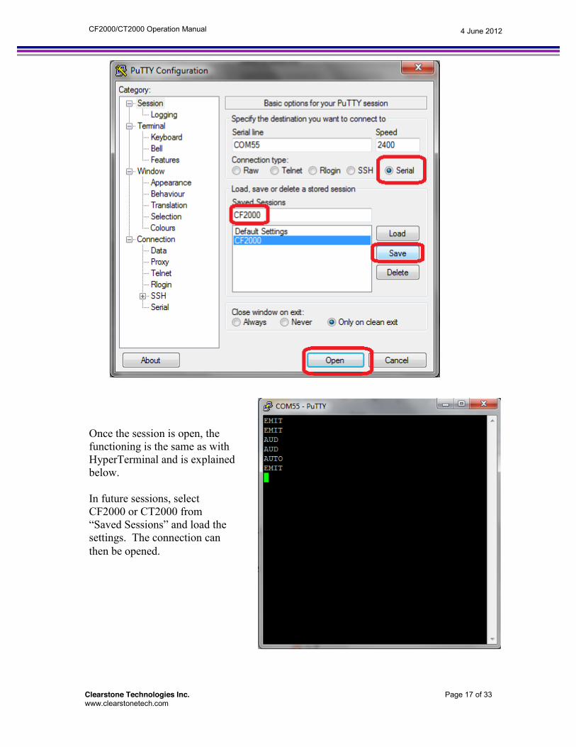
After the COM port number is known, open Putty by running putty.exe. In Putty, select the “Serial” tab from the left menu. Enter the COM port number as earlier determined. Speed = 2400, Data bits = 8, Stop bits = 1, Parity = none, Flow Control = none. After this data is entered, select the “Session” tab from the left menu. Select “Serial” in the connection type Enter CF2000 or CT2000 as the Session Name and Save for easier access in the future. Open the connection.
Clearstone Technologies Inc. Page 17 of 33 www.clearstonetech.com
4 June 2012 CF2000/CT2000 Operation Manual
Once the session is open, the functioning is the same as with HyperTerminal and is explained below. In future sessions, select CF2000 or CT2000 from “Saved Sessions” and load the settings. The connection can then be opened.

Clearstone Technologies Inc. Page 18 of 33 www.clearstonetech.com
4 June 2012 CF2000/CT2000 Operation Manual
Typing commands to the CF2000/CT2000 will now be displayed in the terminal window and sent to the CF2000/CT2000 when carriage return is pressed. This is a good time to plug in a LED head to the back panel of the CF2000/CT2000. Position the CF2000/CT2000 so the displays on the front panel can be easily seen to confirm that the CF2000/CT2000 is responding to the commands. Note that the CF2000/CT2000 requires all commands be in CAPS and that neither Delete nor Backspace is recognized. If an improper command is sent, it will respond with the letter “E” to indicate an error. Hit carriage return to move to the next line for a new command. Note that some of the commands are different between the CF2000 and CT2000. For example, the CF2000 has only one power level setting so the power level command is 4 bytes long, the CT2000 has power level settings for each channel so the power level command is 5 bytes long.
The example above shows the script for a typical session where the user first checks the existing power level (100%), minutes and seconds setting (0:10), then changes the power level to 15% and time to 0:30 before turning the LED on. The details of the exchange above can be interpreted as:
x The user typed “P” and carriage return <CR>. This is the inquiry for the power setting. The CF2000 responded by overtyping the original “P” with “P100”. This indicates the power setting was at 100%. Your result might vary depending on the state of your CF2000.
x The user typed “MIN” <CR>. This is the inquiry for the minute time setting. The CF2000 responded by overtyping the original “MIN” with “MIN00”. This indicates the minute setting was at 00 minutes. Your result might vary depending on the state of your CF2000.
x The user typed in “SEC” <CR>. This is the inquiry for the second time setting. The CF2000 responded by overtyping the original “SEC” with “SEC10”. This indicates the second setting was at 10 seconds. Your result might vary depending on the state of your CF2000.
x The user typed in “P015”<CR>. This is the instruction to set the power to 15%. Check the CF2000, the front display for the power should have changed from 100% to 15%.
x The user typed in “SEC30”<CR>. This is the instruction to set the seconds to 15. Check the CF2000, the front display for the seconds should have changed from 10 seconds to 30 seconds.
x The user typed in “EMIT1”<CR>. This is the instruction to turn on the output to the LED heads. If an LED head is plugged in, it should now be emitting light.
Clearstone Technologies Inc. Page 19 of 33 www.clearstonetech.com
4 June 2012 CF2000/CT2000 Operation Manual
Command Descriptions This section describes the various commands for the CF2000/CT2000 and related parameters. If a command is only valid for the CF2000 or CT2000, it will be indicated next to the command name. Command Set Format Each command code is composed of two to four alpha characters and an optional numeric parameter. If the command is sent without the numeric parameter, the instrument assumes the command is a request for status. When the command is a status request, the receiver returns a string consisting of the command followed by the current setup for that command. Commands must be entered using upper case characters. All commands are terminated by a carriage return <CR>. Do not include spaces between a command and its associated numeric parameter. Data returned from the receiver will be terminated with a <CR><LF>. Remote Commands The commands described the succeeding pages are available to the user for remote communication with and operation of the CF2000/CT2000. In the descriptions of these commands, the following conventions are used: 1. A lowercase "x", “y” or “z” in the command or returned data syntax represents a numeric value, which is associated with a functional selection. (For instance the command “MINxx” for setting the minutes would be typed “MIN15” if the operator wishes to set the time to 15 minutes.) 2. All command must be terminated with a carriage return character <CR>. 3. No spaces or null characters may be used. If an illegal command is received by the CF2000/CT2000 or if the input buffer overflows, the CF2000/CT2000 will respond with an error E<CR><LF>. A colon character “:” (no carriage return) can be sent at any time to “flush” the input buffer of the CF2000/CT2000. Audio Turns on or off the audio indicator on the CF2000/CT2000. Syntax: AUDx Parameters: Audio on or off (x): 0 = Audio indicator turned off 1 = Audio indicator turned on Examples: To turn on the audio indicator, send the following command: AUD1<CR> The CF2000 will respond with AUD<CR><LF> To verify the audio indicator status, send the following command: AUD<CR> If the audio indicator is on, the receiver will respond with: AUD1<CR><LF> Auto Sets the CF2000/CT2000 to auto or manual mode. Syntax: AUTOx Parameters: Auto on or off (x): 0 = Auto mode turned off (manual or count-up mode) 1 = Auto mode turned on (count-down mode) Examples: To set the CF2000 to auto mode: AUTO1<CR> The CF2000/CT2000 will respond with AUTO<CR><LF> To verify the current mode, send the following command: AUTO<CR> If the CF2000/CT2000 is in auto mode, the receiver will respond with: AUTO<CR><LF>

Clearstone Technologies Inc. Page 20 of 33 www.clearstonetech.com
4 June 2012 CF2000/CT2000 Operation Manual
Channel Selection (CF2000 Only, see Power Level command for the CT2000) Enables and disables the LED heads connected to the CF2000. The CF2000 has three output channels for LED heads. Channel 1 is the farthest from the USB port. Channel 3 is closest to the USB port. Note: The channel settings are not stored in EEPROM, if power is turned off, the CF2000 will revert to having all channels enabled when power is turned back on. Syntax: CHxyz Parameters: Channel 1 on or off (x) Channel 2 on of off (y) Channel 3 on or off (z) 000 = sets all channels off 001 = sets only channel 3 on, others off 010 = sets only channel 2 on, others off 100 = sets only channel 1 on, others off 011 = sets channels 2 and 3 on, channel 1 off 101 = sets channels 1 and 3 on, channel 2 off 110 = sets channels 1 and 2 on, channel 3 off 111 = all channels on Examples: To set the CF2000 UV emission to only occur on channels 1 and 2 : CH110<CR> The CF2000 will respond with CH<CR><LF> To check the current emission channel settings, send the following command: CH<CR> If the CF2000 has all channels on: CH111<CR><LF> Emit Starts or stops UV light emission. Syntax: EMITx Parameters: Emission on or off (x): 0 = Turn UV LEDs off. 1 = Turn UV LEDs on. Examples: To start UV light emission: EMIT1<CR> The CF2000/CT2000 will respond with EMIT<CR><LF> To verify the UV emission status, send the following command: EMIT<CR> If the UV emission is on, the receiver will respond with: EMIT1<CR><LF> Lock Locks out the front panel keys (except audio and emit keys). Note: The Lock setting is not stored in EEPROM, if power is turned off, the CF2000/CT2000 will revert to being unlocked when power is turned back on (unless the back-panel key is in lock position). Syntax: LOCKx Parameters: Lock on or off (x): 0 = Front panel lock turned off (all keys available) 1 = Front panel lock turned on (only audio and emit keys available) Examples: To disable the front panel keys: LOCK1<CR> The CF2000 will respond with LOCK<CR><LF> To verify the lock status, send the following command: LOCK<CR> If the CF2000/CT2000 lock is set, the receiver will respond with: LOCK1<CR><LF> Note: The lock status is not saved by the CF2000/CT2000 when it is turned off. The default value will be “lock off” when the device is turned back on.

Clearstone Technologies Inc. Page 21 of 33 www.clearstonetech.com
4 June 2012 CF2000/CT2000 Operation Manual
Minutes Sets the minutes value for UV emission while in auto mode. For auto mode, returns the current minutes value while UV emission is in progress. For manual mode, returns the minutes value for UV emission that has occurred. While UV emission is not in progress, the CF2000/CT2000 will return zero for manual mode and the current minutes value setting in auto mode. Syntax: MINxx Parameters: Number of minutes (xx): 00 = Zero minutes 01 = One minute … 59 = 59 minutes Examples: To set the CF2000/CT2000 UV emission time minutes value to 5: MIN05<CR> The CF2000/CT2000 will respond with MIN<CR><LF> To check the current emission time minutes value, send the following command: MIN<CR> If the CF2000/CT2000 is in auto mode and the minutes value is 1: MIN01<CR><LF> Mode Sets the function of the front panel Trig button and the footswitch input to either “normal” mode or “momentary” mode. In ”normal” mode, pushing the Trig button or footswitch will toggle the LED either on or off. In “momentary” mode, the LEDs will be on only while the Trig button or footswitch is pushed. While in “momentary” mode, if Auto is selected (see Auto command above), the LEDs will turn off when the timer counts down to 0. To re-start emission, the Trig button or footswitch must be released and then can be pushed again. Syntax: MODEx Parameters: Mode (x): 0 = Normal mode 1 = Momentary mode Examples: To set the CF2000/CT2000 UV emission mode to momentary: MODE1<CR> The CF2000/CT2000 will respond with MODE<CR><LF> To check the current mode, send the following command: MODE<CR> If the CF2000/CT2000 is in normal mode: MODE0<CR><LF> Power Level Sets the variable power level for all channels in the CF2000/CT2000 over the range 0-100. Syntax: CF2000: Pxyz or CT2000: Pwxyz Parameters: Channel (w): (CT2000 only) 0 = All channels (0 is valid for setting channel power level only, not reading it back) 1 = Channel 1 2 = Channel 2 3 = Channel 3 Power level (xyz): 000 = sets power level to 0% 001 = sets power level to 1%. . 050 = sets power level to 50% . 099 = sets power level to 99% 100 = sets power level to 100%

Clearstone Technologies Inc. Page 22 of 33 www.clearstonetech.com
4 June 2012 CF2000/CT2000 Operation Manual
Note: To turn a CT2000 channel on or off, use the Power Level command and set the power level to 000. there is no Channel command on the CT2000. Examples: To set the CF2000 UV emission power level value to 15% : P015<CR> The CF2000 will respond with P<CR><LF> To check the current emission power level value, send the following command: P<CR> If the CF2000 power level value is 10%: P010<CR><LF> To set the CT2000 UV emission power level value for channel 1 to 15% : P1015<CR> The CT2000 will respond with P1<CR><LF> To check the current emission power level value, send the following command: P2<CR> If the CT2000 power level value is 10%: P2010<CR><LF> To set all channels of the CT2000 to 50%: P0050<CR> Reset Resets the CF2000/CT2000 to factory settings. Syntax: RESET Parameters: None Examples: To reset the CF2000/CT2000: RESET<CR> Note: The CF2000/CT2000 will not respond to this command. After sending this command to the CF2000/CT2000, there will be an approximately 3 second delay before the CF2000/CT2000 will accept any other commands. When this command is received, the factory settings will be stored in EEPROM and the CF2000/CT2000 will restart. Seconds Sets the seconds value for UV emission while in auto mode. For auto mode, returns the current seconds value while UV emission is in progress. For manual mode, returns the seconds value for the UV emission that has occurred. While UV emission is not in progress, the CF2000/CT2000 will return zero for manual mode and the current seconds value setting in auto mode. Syntax: SECxx Parameters: Number of seconds (xx): 00 = Zero seconds 01 = One second … 59 = 59 seconds Examples: To set the CF2000/CT2000 UV emission time seconds value to 15 : SEC15<CR> The CF2000/CT2000 will respond with SEC<CR><LF> To check the current emission time seconds value, send the following command: SEC<CR> If the CF2000/CT2000 is in auto mode and the seconds value is 10: SEC10<CR><LF> Status (CF2000 only) Reads the status of the LED heads. Syntax: STAT Parameters: Status(x): 0 = LED head fault detected 1 = LED head(s) operating properly Examples: To read the status of the LED heads: STAT<CR> The CF2000 will respond with STAT1<CR><LF> if the LED heads are operating properly. Note: The performance monitor circuitry only operates if the Power Level is greater than 25%.

Clearstone Technologies Inc. Page 23 of 33 www.clearstonetech.com
4 June 2012 CF2000/CT2000 Operation Manual
Resetting the CF2000/CT2000 to Factory State To set the CF2000/CT2000 EEPROM settings to the factory default state, perform the following steps:
1) Turn off power to the CF2000/CT2000. 2) Push and hold the Auto and Trig front panel buttons. 3) While pushing the buttons, turn on power to the CF2000/CT2000. The 3 front panel LEDs will
light. 4) When the 3 front panel LEDs turn off, release the Auto and Trig buttons. 5) The CF2000/CT2000 will now restart with the factory settings stored in EEPROM. Important
note: any settings that are not controllable through the front panel (e.g. Mode), must be re-programmed via remote commands to the desired settings.
The factory default settings are as follows: Auto mode: on Channel selection: all channels on Lock: off (unless back panel key in lock position) Minutes: 0 Seconds: 10 Audio: on Power level: 100% (all channels of the CT2000) Mode: normal mode

Clearstone Technologies Inc. Page 24 of 33 www.clearstonetech.com
4 June 2012 CF2000/CT2000 Operation Manual
Installing CF2000 RS232 Adapter Option: The CF2000 RS232 adapter option is available at through your local Clearstone dealer. Contact information for your local Clearstone dealer can be found at www.clearstonetech.com. Adapter kit parts list:
A. Adapter cable. Qty. 1 B. Aluminum adapter plate. Qty. 1 C. Fillister screw (small Phillips head) 4-40 thread Qty. 1 D. Long hex shaped screw (Jack Screw) 4-40 thread Qty. 1 E. Short hex shaped screw (Jack Screw) 4-40 thread Qty. 1
Procedure:
1) Remove the nine screws holding the top of the case to the unit. 2) Disconnect cables between the top of the case and the power supply. 3) Remove USB cable if installed. 4) Attach adapter block to the top of the case using the included Fillister screw (small Phillips head)
screw. See figure 1. Tighten securely. 5) Thread the end of the cable with the small connector through the opening in the adapter block. See
Figure 2. 6) Attach connector to the printed wiring board as shown in Figure 3, making sure that the pins align
with the holes in the connector. Also, verify that the small triangle on the connector is nearest the square pad on the printed wiring board. The arrow on Figure 3 shows the location of the square pad.
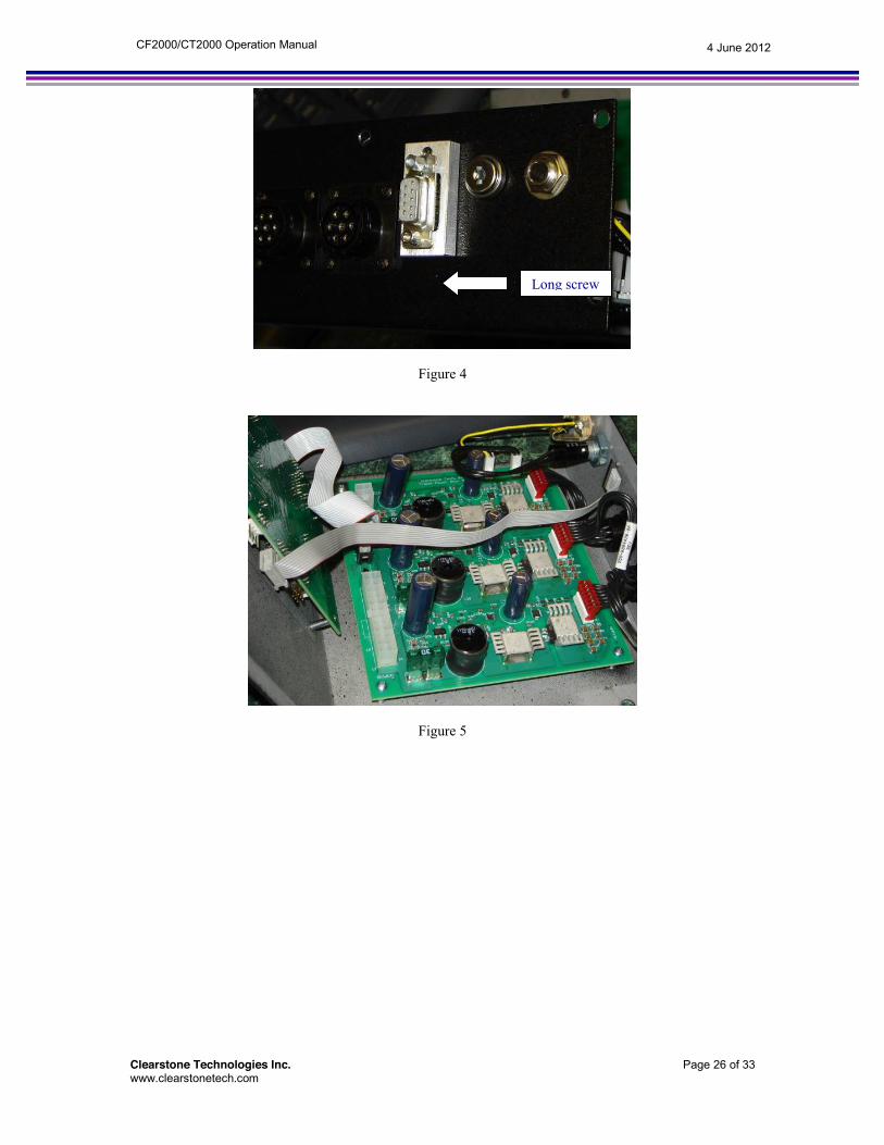
7) There were two hex shaped screws (Jack screws) included with the adapter kit. These are used to attach the RS-232 connector to the adapter block. See Figure 4. The short hex shaped screw (Jack screw) is used closest to the Fillister screw (small Phillips head) screw. The long hex shaped screw (Jack screw) is used on the opposite end. The long screw will go through the adapter block and thread into the case. Once the screws are attached, tighten securely. Figure 5 shows the completed assembly.
8) Re-attach the power supply cables and the top of the case to the base. Make sure that none of the cables are pinched between the two halves of the case.
Figure 1

Clearstone Technologies Inc. Page 25 of 33 www.clearstonetech.com
4 June 2012 CF2000/CT2000 Operation Manual
Figure 2
Figure 3
Clearstone Technologies Inc. Page 26 of 33 www.clearstonetech.com
4 June 2012 CF2000/CT2000 Operation Manual
Figure 4
Figure 5
Long screw

Clearstone Technologies Inc. Page 27 of 33 www.clearstonetech.com
4 June 2012 CF2000/CT2000 Operation Manual
Footswitch Input Circuit Controller Types: CF1000, CF2000 & CT2000 This schematic is provided so the user can use the footswitch input for alternate remote control methods such as PLCs, relay switches etc.
The footswitch input can be found on the rear panel of the CF2000/CT2000 controller. The CF1000, CF2000 and CT2000 all use a Switchcraft part number 12A panel mount ¼” input jack or equivalent. The effective circuit is shown in the figure above. The outer conductor is sits at ground while the inner conductor is pulled up to 5 volts with a 20k ohm resistor. In addition, a 0.1microfarad capacitor and 5k ohm resistor have been added to avoid an erroneous response due to “switch bounce”. The standard controller firmware is designed to trigger an emission cycle when the footswitch or membrane switch is momentarily closed. The CF2000/CT2000 also has a “momentary” mode available that is programmed via a remote command. See the remote operation section for details.

Clearstone Technologies Inc. Page 28 of 33 www.clearstonetech.com
4 June 2012 CF2000/CT2000 Operation Manual
Safety Guidelines and Information Disclaimer: Equipment users are responsible for operation of their UV LED equipment in compliance with their local and national regulations. These notes are provided for informational purposes only, and are not for a guarantee for safe operating conditions.
A letter posted on the topic of OSHA –mandated employee exposure limits to ultraviolet radiation at the OSHA website. The letter by Richard E Fairfax, Director, Directorate of Enforcement Programs, was dated February 25, 2003 and addressed to James. R. Bolton, Ph.D., Executive Director and International Secretary, International Ultraviolet Association, at 628 Cheriton Crescent, N.W. Edmonton, AB, Canada T6R 2M5. We have lifted the following portion of the letter. “Scenario: Workers using ultraviolet (UV) lamps may have skin or eye exposure to stray ultraviolet light emissions. Such workers need to know acceptable levels of irradiance (measured in milliwatts per square centimeter (mW/cm2)) and how to monitor for stray radiation. The exposed UV dose would be in units of millijoules per square centimeter (mJ/cm2). [In most cases, the UV lamp would be a low pressure mercury lamp, so almost all the UV light is at 253.7 nanometers (nm).] Question: Are there any OSHA regulations for workplace exposure limits to ultraviolet radiation? Response: OSHA has two standards that cover employee exposure to radiation: Nonionizing Radiation (29 CFR 1910.97) and Ionizing Radiation (29 CFR 1910.1096). You may access a copy of our radiation standards from our website at http://www.osha.gov. The non-ionizing radiation standard only covers the radio frequency region, including microwaves. The ionizing radiation standard covers alpha, beta, gamma, and X-rays; neutrons; high-speed electrons and protons; and other atomic particles; but does not include sound or radio waves, or visible, infrared, or ultraviolet light. Therefore, there are no OSHA-mandated employee exposure limits to ultraviolet radiation.”
For emphasis, we repeat the last sentence: “Therefore, there are no OSHA-mandated employee exposure limits to ultraviolet radiation. As of April 21, 2009, the posted letter could be found at the internet link:
(http://www.osha.gov/pls/oshaweb/owadisp.show_document?p_table=INTERPRETATIONS&p_id=24755).
In the following paragraph, the letter suggests guidance for laser hazards in the OSHA Technical Manual (TED 1-0.15A, Section III – Chapter 6). The letter notes that the light hazard from lasers is different from that of mercury lamps. Clearstone believes there will also be substantial differences between lasers and LEDs. With this in mind, we did find some comments on the impact of UV radiation on the eyes and skin. Clearstone products produce light in the UV-A wavelength range with the peak wavelengths of 365 nm, 385 nm and 395 nm. From the OSHA Technical Manual Section III: Chapter 6. http://www.osha.gov/dts/osta/otm/otm_iii/otm_iii_6.html

Clearstone Technologies Inc. Page 29 of 33 www.clearstonetech.com
4 June 2012 CF2000/CT2000 Operation Manual
Lifted from TABLE III:6-3. SUMMARY OF BASIC BIOLOGICAL EFFECTS OF LIGHT
Ultraviolet A (315-400 nm)
Photochemical UV cataract
Pigment darkening Skin burn
Photobiological spectral domain
Eye effects Skin effects
In addition to the qualitative comments above, the letter from Richard Fairfax references the non-governmental organization the American Conference of Governmental Industrial Hygenists (http://www.acgih.org ) as a source of threshold limit recommendations. In 2009, the ACGIH published its annual TLV-BEI, Threshold Limit Value and Biological Exposure Indices. LEDs and mercury gas discharge lamps are Lambertian incoherent sources emitting in all directions unlike lasers that emit a coherent, highly directional beam. The section on UV exposure from traditional mercury gas and discharge lamps can be found on pages 152-154. (http://www.acgih.org/store/ProductDetail.cfm?id=2039). We reference this section because there is no section specifically for UV LEDs. Table 1 is taken from the 2009 TLV-BEI for the closest wavelength ranges relevant to Clearstone’s UV LED products. The doses are the recommended maximum dose for exposed skin or eyes during a typical 8 hour working shift.
Table 1. Recommended maximum doses for UV radiation
Energy dose of 365 nm light for 8 hour shift mJ/cm2 27,000 Energy dose of 385 nm light for 8 hour shift mJ/cm2 57,000 Energy dose of 400 nm light for 8 hour shift mJ/cm2 100,000
The exposure duration can be estimated from the information in table 1 and the emitted
power/area from an UV LED heads. The equation to calculate the exposure duration can be expressed as: Exposure duration (sec) = {Irradiance Received (mW/cm2) / Energy dose(mJ/cm2) The calculated exposure durations are shown in table 2. The first column indicates the irradiance
(W/cm2) received on the exposed skin of the operator. Please see the specific data sheet for the LED head being considered for use. The data sheets indicate the minimum guaranteed light irradiance from the LED head. The typical irradiance from the LED head will be more than the minimum to provide some manufacturing margin. However, the typical irradiance from the LED head will not be more than twice the minimum specification. At the time this document was written, the range of irradiance from Clearstone was from 250 mW/cm2 at the output window of an array of small 365 nm LEDs, to over 4000 mW/cm2 at the focal point from a larger area LED emitting at 400 nm. Table 2 lists irradiance levels much lower than the peak LED outputs since these are likely to be encounter at long working distances from the LED head or from scattered light.

Clearstone Technologies Inc. Page 30 of 33 www.clearstonetech.com
4 June 2012 CF2000/CT2000 Operation Manual
Irradiance 365 nm 385 nm 400 nmmW/cm2 sec sec sec
0.001 27,000,000 57,000,000 100,000,000 0.003 10,800,000 22,800,000 40,000,000 0.005 5,400,000 11,400,000 20,000,000 0.010 2,700,000 5,700,000 10,000,000 0.025 1,080,000 2,280,000 4,000,000 0.050 540,000 1,140,000 2,000,000 0.100 270,000 570,000 1,000,000 0.250 108,000 228,000 400,000 0.500 54,000 114,000 200,000 1.000 27,000 57,000 100,000 2.500 10,800 22,800 40,000 5.000 5,400 11,400 20,000
10.000 2,700 5,700 10,000 25.000 1,080 2,280 4,000 50.000 540 1,140 2,000
100.000 270 570 1,000 250.000 108 228 400 500.000 54 114 200
1,000.000 27 57 100 2,500.000 11 23 40 5,000.000 5 11 20
10,000.000 3 6 10 25,000.000 1 2 4
Table 2. Calculated duration to receive maximum allowed recommended exposure.
The other vertical columns show the recommended maximum cumulative exposure time (sec) during an 8 hour daily work shift for emission at 365 nm, 385 nm and 400 nm. The exposure times are high lighted to indicate the relative hazard of exposure. Since an 8 hour work shift has 28,800 seconds, an operator may be continuous exposed to the blue shaded irradiances during an 8 hour shift. Depending on the irradiance level, the green shading indicates recommended maximum cumulative exposures from 1 to 8 hours during an 8 hour shift. In the yellow zones, the recommended maximum cumulative exposure may be from 1 minute to 60 minutes during an 8 hour shift. In the orange region, the recommended maximum cumulative exposure is less than one minute during an 8 hour shift.
Explosion Proofing and Safety
The use of UV-LEDs provides several key advantages in avoiding potential explosions and fire hazards when compared with mercury bulb light sources. Processes associated with painting or coating an item often involve dispersing potentially flammable materials in an atomized or spray form. Spray and powder processes may also result in the accumulation of waste coatings in the form of liquids, gasses or dusts that may be flammable. Some applications may involve curing materials in an environment that may include potentially explosive gasses.

Clearstone Technologies Inc. Page 31 of 33 www.clearstonetech.com
4 June 2012 CF2000/CT2000 Operation Manual
Operating temperature and pressure LEDs are operated at very safe temperatures compared to mercury arc lamps. Unlike mercury bulb
UV sources, LEDs are more energy efficient and have better reliability when operated at lower temperatures. Clearstone designs its UV-Vis LED equipment so the junction temperature of the LED is less than 115C. The LED junction is the hottest part of the entire LED head and located deep within the semiconductor die. The die for the UV LEDs are packaged inside a chip case. The thermal design of the LED head keeps the outside of the chip case less than 70C. The outer shell of the LED head will be less than 40C provided the ambient air temperature is below 30C. The LEDs may fail if they are electrically or thermally overstressed. If the fans are blocked or functionally defeated while the LEDs are driven at full power, thermal overstress might occur after an extended period of time (probably hours). The failed LEDs become an open circuit and no longer draw current or electrical energy from the controller. After enough LEDs fail so that the head effectively becomes an open circuit, the LED head will no longer draw power from the controller power supply. Then the LED head will slowly cool down as the heat dissipates.
The chip cases for the 365 LEDs enclose the die in an inert nitrogen environment at one atmosphere. The gas in the 365 nm chip case is non-flammable, safe, and will not explode. The chip cases for the 395 nm LEDs enclose the die in a soft, non-flammable silicone gel. The chip case enclosure materials for the 395 nm LEDs are also non-flammable, safe and will not explode. The LEDs can be housed behind a drop resistant UV transparent acrylic window. Even if the UV transparent acrylic window is compromised and the LED chip cases are broken there is no ignition source to be exposed.
UV LEDs are very safe compared to short arc mercury bulbs with regards to temperature and explosion potential. According to Osram’s “Environmental Information on Short-Arc Mercury Lamps (HBO)”, the temperature of the arc inside the glass bulb is 10,000C while the inside wall of the glass reaches 800C (http://www.osram.com/pdf/about_us/environment/hbo_2007.pdf). The pressure of the gas under operating conditions reaches 30-70 bar (1 bar = 0.98 atmosphere). The hot plasma of a high intensity discharge tube is contained by breakable glass since a plastic or acrylic window could not withstand the temperature of the inner walls. A rupture of the pressurized bulb will also release toxic mercury. Other types of high intensity discharge lamps using mercury or mercury xenon gas have similar heat and explosion hazards. Operating voltage and grounding
LEDs generate light with low voltage and without an electrical arc. The typical forward voltage for a single UV LED is between 3.5 to 4.5 volts. The light generation is inside the semiconductor chip and does not require an electrical arc or high starter voltage. Most LED heads designed by Clearstone operate in the +18V to +48V range. The +48 volt drive is very safe relative to wall voltages of 115VAC.
A grounded external case is a safety precaution that prevents internal voltages from giving an operator an electrical shock and prevents the internal voltages from causing a spark when various pieces of electrical equipment come in contact. A grounded case is a standard feature for all Clearstone LED heads and LED controller power supplies. Clearstone’s CF1000, CF2000 and CT2000 controller power supplies have a dedicated pin for case grounding that is used to ground the LED heads.
Commonly used UV mercury bulbs require an initial high voltage pulse to break down the enclosed vapors into plasma. According to the Hamamatsu short arc mercury-xenon catalog (http://sales.hamamatsu.com/assets/pdf/catsandguides/Lmps_super_quiet_mercury_xenon.pdf) the recommended voltage is a couple tens of thousands of volts. If not carefully contained, these voltages are potentially lethal and capable of igniting flammable vapors. LEDs do not use high volt starting voltages. Cable shielding
All Clearstone LED heads use shielded cable. The shielding prevents electro magnetic interference (EMI) when the LEDs are switched on and off. The shielding is a conductive foil or braided wires that surrounds the current carrying cables. A braided wire shield can endure repeated bending up to millions of cycles. These cables are typically used in applications with frequent flexing and the cables are manufactured with more flexible rubber jackets. A conductive foil is usually lighter in weight than a braided wire but can only be bent for tens of thousands of cycles before becoming damaged. Foil shielded cables are often used in fixed deployments and usually have stiff plastic jackets. The emission of EMI by the proposed LED head is expected to be infrequent, since it mostly occurs when the LED head is turned on or off. Since the LED curing equipment may be used near sensitive electrical equipment, it is prudent to use shielding, even if the shielding adds weight to the cable

Clearstone Technologies Inc. Page 32 of 33 www.clearstonetech.com
4 June 2012 CF2000/CT2000 Operation Manual
General safety approach
Clearstone designs and builds all its equipment for successful certification under UL, NFPA or other safety or regulatory standards. Critical components have been selected with maintaining our CE and safety certification in mind. For instance, UL or CE approved power supplies are used in all Clearstone products. The connectors for the VAC input and the connectors for the cable to the LED head are all UL certified and used under UL approved conditions. The wiring in the LED head, cable and controller are all sized to be within UL approved specifications. The use of shielded cable and case ground also facilitate ready safety and FCC approvals. References: OSHA Website on April 21/2009: http://www.osha.gov/pls/oshaweb/owadisp.show_document?p_table=INTERPRETATIONS&p_id=24755 American Conference of Governmental Industrial Hygienist (ACGIH). (www.acgih.org) 2009 Annual TLV-BEI, Threshold Limit Value and Biological Exposure Indices, pages 152-154.

Clearstone Technologies Inc. Page 33 of 33 www.clearstonetech.com
4 June 2012 CF2000/CT2000 Operation Manual
EC Declaration of Conformity The Manufacturer Clearstone Technologies Inc.
5301 Humboldt Ave S. Minneapolis, MN 55419
declares that the following product Controller/Power Supply CF2000REV3.0 when installed according to the product documentation installation instructions, is in conformity with the following EC Directives: EN 55011: 2007 +A2: 2007 Group 1 Class A Limit concerning radio-frequency equipment. - This standard can be used to show conformity to the Electromagnetic Compatibility (EMC) Directive 89/336/EEC. FCC Part 15 Subpart B Class A Limit regulates radio-frequency equipment 2006/95/EC Low Voltage Equipment Directive (regulates voltage levels of equipment) June 4, 2012 _________________________________
(Richard Sahara) President


![Ct2000 pro plus_manual_english[1]](https://img.pdfslide.us/doc/110x75/5552da10b4c90532498b4a42/ct2000-pro-plusmanualenglish1.jpg)


