Embed Size (px)
Citation preview

Mechatronics Group
OPERATION MANUAL
Diaphragm Pump TD/TD2 Series
TD-08, 15, 20/TD2-25 Thank you for purchasing Diaphragm Pump.
Introduction This operation manual describes how to ensure safe and prolonged use of the diaphragm pump, and how to obtain the best performance of the pump. Be sure to read through this operation manual before using the pump. Particularly, be sure to observe the prohibitive instructions and precautions indicated with [WARNING] and [CAUTION] symbols in this operation manual. Read through this operation manual carefully, and keep it in place for your reference.
Contents 1 Definitions of [WARNING] and [CAUTION] ..... 2 2 Before Use/During Use ..................................... 2
2-1. To ensure safety and prevent hazard .................... 2 2-2. Exemption from responsibility................................ 3
3 Part Names......................................................... 3 4 Checking Package Contents............................ 4 5 Operating Principle ........................................... 4 6 Installation ......................................................... 5
6-1. Precautions for installing and mounting the pump . 5 6-2. Precautions for piping (Connections with
suction port and discharge port) ............................ 6 6-3. Precautions for piping
(Connection of air pressure) .................................. 6 7 Operation ........................................................... 7
7-1. Checking the pump before operation..................... 7 7-2. Checking the pump through trial run...................... 7 7-3. Checking the pump in operation ............................ 7
8 Maintenance (Parts) .......................................... 8 8-1. Daily inspection
(Check the pump every two or three days.) ........... 8 8-2. Periodic inspection ................................................ 9
9 Maintenance Procedure ................................. 10 9-1. Preparations for maintenance ..............................10 9-2. Check valve disassembly and
inspection procedure............................................10 9-3. Check valve assembly procedure ........................ 11 9-4. Diaphragm disassembly and
inspection procedure............................................ 11 9-5. Diaphragm assembly procedure ..........................12 9-6. Final inspection ....................................................12
Fig. 3 Parts Disassembly Drawing (1) ............13 Fig. 4 Parts Disassembly Drawing (2) ............14
10 Major Dimensions ........................................... 15 11 Terminology..................................................... 15 12 Warranty........................................................... 15
12-1. Warranty period....................................................15 12-2. Scope of warranty ................................................15 12-3. Exemption from scope of warranty.......................15 12-4. Repair parts..........................................................15
WARNING
To use the pump safely: Improper handling of the diaphragm pump causes deterioration of the pump performance, which can result in a serious accident. To avoid an accident, be sure to read through this operation manual carefully to understand the contents thoroughly, before handling the pump.
Make sure that this operation manual is delivered to actual users. After reading this operation manual, keep it carefully for reference.
This product has been designed and manufactured as general industrial mechanical components.

2 Definitions of [WARNING] and [CAUTION] / Before Use/During Use Regarding [WARNING] and [CAUTION], the following definitions and indication symbols are used in this operation manual. [WARNING] and [CAUTION] indicates the contents that demand particular attention to ensure safety. These instructions provide important information to prevent possible injuries and property damage. When handling the pump, be sure to observe these instructions.
WARNING Indicates potentially hazardous conditions that can result in death, serious injury or serious property damage if this product is improperly handled.
CAUTION Indicates potentially hazardous conditions that may result in middle/slight injury or property damage if this product is improperly handled.
This product has been designed and manufactured as general industrial mechanical components.
2 Before Use/During Use 2-1. To ensure safety and prevent hazard
WARNING
Be sure to observe the warnings, cautions and prohibitive instructions described in this operation manual. Failure to observe these instructions causes damage to the pump, and can result in damage to the surrounding machinery or injuries.
If the diaphragms are damaged, the fluid spouts from the exhaust port through the air pressure valve, or air is mixed with the fluid. This can result in a serious accident depending on the property of the fluid.
To use a fluid that may cause injuries or property damage, be sure to take appropriate preventive measures (exhaust disposal measures etc.), and be sure to observe the following instructions.
When this pump is used in an atmosphere that may cause spontaneous ignition, or when a highly flammable fluid is fed, circulated or used for cleaning at a high speed, this can cause electrostatic sparks, ignition or heating which gives shock to the human body, and can result in injuries or property damage from a fire or explosion. Be sure to ground the pump with the supplied ground cable, and provide ventilation depending on the operating environment.
Make sure that the supplied pressure does not exceed the maximum operating pressure (0.7 MPa). Operating the pump under a pressure higher than the maximum operating pressure can result in pump damage, causing injuries or property damage. Be sure to purchase the air pressure regulator or air pressure filter regulator, and mount it to the pump.
Be sure not to use a fluid incompatible with the material of the fluid contact parts of the pump, or a solution that may cause explosion. Using such a fluid or solution develops a chemical change involving extremely hazardous explosion. This can result in injuries (including death) or damage to properties (building, equipment, etc.).
This pump cannot use a fluid that may affect the materials of the fluid contact parts and the diaphragms. Referring to the compatibility table included in the catalog, select the pump model compatible with the fluid being used. Using a pump incompatible with the fluid may result in fluid leak or damage. For compatibility between the pump and fluid, consult TAIYO sales office.
Before daily operation, be sure to check the pump for fluid leak. If there is a defect, do not use the pump. Contact TAIYO to order inspection or repair.

Before Use/During Use / Part Names 3
WARNING
Do not use consumable parts (diaphragms etc.) longer than the replacement interval specified in “Maintenance” of this manual, and conduct early maintenance. Do not use a part that has been left for at least one year from the date of purchase, even if it has not been used. It may be deteriorated by secular changes.
If abnormality is found in pump operating conditions, stop operation, and contact the nearest TAIYO sales office listed on the last page.
To use a fluid with toxicity or smell, ensure through ventilation.
Do not discharge chemicals or other harmful substances that the pump handles directly onto the installation floor. For disposal of harmful substances, follow the regulations applied to the substances.
If the pump availability factor per certain period increases, replace the consumable parts (diaphragms etc.) earlier than the specified replacement interval.
2-2. Exemption from responsibility Use the pump properly according to this operation manual. Failure to observe the warnings, cautions and prohibitive instructions described in this manual, or improper handling of the pump causes damage to the pump, and may result in damage to the surrounding machinery, or injuries. TAIYO shall not responsible to any damage attributable to such conditions. Also, TAIYO shall not be responsible to any damage attributable to users' modification of this product.
3 Part Names
Cartridge
Ball Valve sheet
Diaphragm
Spool
ManifoldCover
Air valve
Mounting foot
4 Checking Package Contents/Operating Principle
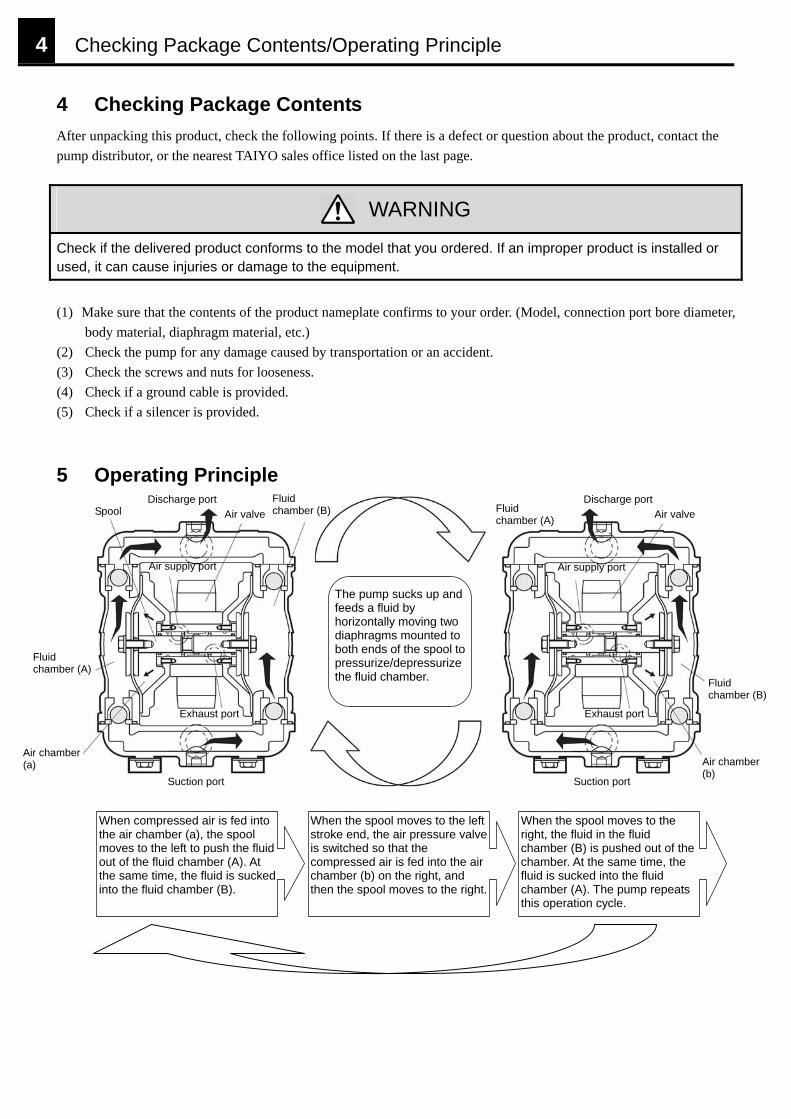
4 Checking Package Contents After unpacking this product, check the following points. If there is a defect or question about the product, contact the pump distributor, or the nearest TAIYO sales office listed on the last page.
WARNING
Check if the delivered product conforms to the model that you ordered. If an improper product is installed or used, it can cause injuries or damage to the equipment.
(1) Make sure that the contents of the product nameplate confirms to your order. (Model, connection port bore diameter,
body material, diaphragm material, etc.) (2) Check the pump for any damage caused by transportation or an accident. (3) Check the screws and nuts for looseness. (4) Check if a ground cable is provided. (5) Check if a silencer is provided.
5 Operating Principle
Fluid chamber (B)
Discharge port Discharge port Fluid chamber (A)
Spool Air valve Air valve
Air supply port Air supply port
The pump sucks up and feeds a fluid by horizontally moving two diaphragms mounted to both ends of the spool topressurize/depressurize the fluid chamber.
Fluid chamber (A)
Fluid chamber (B)
Exhaust port Exhaust port
Air chamber (a) Air chamber
(b) Suction port Suction port
When compressed air is fed into the air chamber (a), the spool moves to the left to push the fluid out of the fluid chamber (A). At the same time, the fluid is sucked into the fluid chamber (B).
When the spool moves to the left stroke end, the air pressure valve is switched so that the compressed air is fed into the air chamber (b) on the right, and then the spool moves to the right.
When the spool moves to the right, the fluid in the fluid chamber (B) is pushed out of the chamber. At the same time, the fluid is sucked into the fluid chamber (A). The pump repeats this operation cycle.
Installation 5
6 Installation 6-1. Precautions for installing and mounting the pump The pump service life depends on whether the installation condition is proper or not. Pay attention to the following points:
WARNING
When this pump is used in an atmosphere that may cause spontaneous ignition, or when a highly flammable fluid is fed, circulated or used for cleaning at a high speed, be sure to ground the pump with the supplied ground cable, and provide ventilation depending on the operating environment. Failure to observe this instruction can result in injuries and property damage from a fire or explosion.
Make sure that load and vibration of the piping is not applied to the pump body. Otherwise, a fluid leak may occur, and air may be mixed with the fluid. This may result in injuries or property damage depending on the property of the fluid.
CAUTION
For connections of the pump suction and discharge ports, use a hose or flexible tube to absorb pump vibration.
Never attempt to step on, or hang down from the diaphragm pump. Such an action may result in injuries, or causes a failure of the pump.
Set the suction head as small as possible. The maximum suction head is approx. 6 m (when fresh water is used). Providing a larger suction head increases the suction resistance. Also, when the fluid viscosity is high (3000 mPa s), the suction resistance becomes large. This may reduce the discharge rate, and cause pump internal damage due to shortened life span of the diaphragms, or cavitation*. (* Refer to “Terminology”)
To install the pump, be sure to take appropriate vibration-absorbing measures in consideration of the installation place.
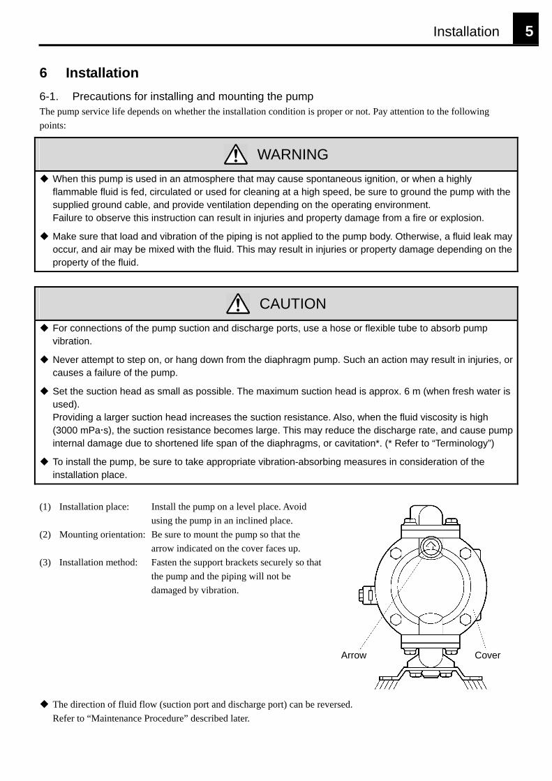
(1) Installation place: Install the pump on a level place. Avoid
using the pump in an inclined place. (2) Mounting orientation: Be sure to mount the pump so that the
arrow indicated on the cover faces up. (3) Installation method: Fasten the support brackets securely so that
the pump and the piping will not be damaged by vibration.
Arrow Cover
The direction of fluid flow (suction port and discharge port) can be reversed. Refer to “Maintenance Procedure” described later.
6 Installation
6-2. Precautions for piping (Connections with suction port and discharge port)
CAUTION
Select appropriate pipes in consideration of size, fluid-compatibility and pressure resistance. Using improper pipes may cause a fluid leak or pump failure.
Before connecting the pipes, flush the pipes to prevent swarf, sealing tape waste, rust or other foreign bodies from entering the piping. Intrusion of foreign bodies will cause pump malfunction.
During piping, make sure that the pump body is not subjected to lateral load. Otherwise, the screws in the pump suction port and discharge port may be damaged, causing a sealing failure or other troubles.
For connections with the pump suction port and discharge port, use hoses or flexible tubes to absorb pump vibration.
Use pipes that will not crash under negative pressure when the pump sucks up the fluid.
Use pipes with an inner diameter larger than the discharge/suction port bore diameter. If the pipe inner diameter is too small, the pump cannot provide sufficient performance.
To protect the pump, mount a filter or strainer to the pump suction port. 6-3. Precautions for piping (Connection of air pressure)
CAUTION
Before connecting the air pressure pipe, make sure that the air supply is stopped. Otherwise, the pump may abruptly operate, resulting in injuries and property damage.
Make sure that the supplied air pressure does not exceed the maximum operating pressure. Supplying a higher air pressure may result in injuries and property damage. (Operating air pressure: 0.2 to 0.7 MPa)
After operation is completed, or during night, stop supplying air pressure, and release residual pressure from the piping and the pump. If the piping has a crack or the diaphragms are damaged when the air pressure is supplied, the pump continues operation, and the fluid may continue to leak out. Such derivative damages shall be under responsibility of the user.
Never attempt to mix a general antifreeze solution into the oil in the air pressure lubricator mounted to the air pressure supply port. It may have bad influence on the human body. Mount the air pressure filter, regulator and lubricator (three items/set) to the air pressure supply port to supply clean air and lubrication oil. When mounting these components, set the distance from the diaphragm pump as short as possible. The mounting distance has influence on the pump durability and performance.
Mount the air pressure filter, regulator and lubricator (three items/set) to the air pressure supply port at the shortest distance from the diaphragm pump.
For the air pressure piping, use a pipe with an inner diameter larger than the air supply port bore diameter (Rc1/4, TD2: Rc3/8).
To use a new pipe, flush the pipe before connecting it to the pump, to remove swarf, dust or other foreign bodies completely. Foreign bodies in the pipe will cause malfunction of the air pressure valve.
Make sure that the supplied air pressure does not exceed the maximum operating pressure (0.7 MPa).
Operation 7
7 Operation 7-1. Checking the pump before operation
CAUTION
Make sure that the pump has been properly installed, and that the mounting bolts are not loose. Operating the pump with the mounting bolts loosened may result in injuries or damage to the surrounding machinery.
To use a highly flammable fluid, be sure to ground the pump with the supplied ground cable. Operating the pump without connecting the ground cable may result in injuries and property damage from a fire or explosion.
Make sure that the pump has been securely installed on the operation site. Set the pump suction/discharge piping individually. Check the connections with the pump for looseness. Make sure that the air pressure regulator has been set to the minimum operating pressure (0.2 MPa). Make sure that the air pressure lubricator has the lubrication oil <JIS K2213-Class 1 (Additive-free turbine oil ISO VG32)>.
7-2. Checking the pump through trial run
CAUTION
Do not continue idle run for a long period. This may result in unexpected wear, and causes a pump failure.
Make sure that the pump has been properly installed so as to absorb vibration. Check the pump for a fluid leak.
To conduct a trial run, increase the air supply pressure gradually from the minimum operating pressure. After confirming that the pump normally operates, increase the air supply pressure up to the set pressure.
7-3. Checking the pump in operation
CAUTION
For control of discharge rate through adjustment of supplied air pressure, the allowable fluid suction flow rate varies depending on the viscosity and specific gravity of the fluid, suction head and other operating conditions. If the fluid suction flow rate exceeds the specified flow rate, the pump operates at a higher speed, causing cavitation in the fluid. Such a condition rather reduces the discharge rate, and shortens the diaphragm service life. (*Refer to “Terminology”)
It is not dangerous to leave the pump at rest with the discharge port valve closed while air pressure is being supplied. However, if the pump is left in this condition without being watched for a long period or during night, the pump starts operation in case where the fluid leaks from the piping or diaphragms, and continues to discharge the fluid from the leak portion. To leave the pump at rest for a long period, stop supplying air pressure, and open the valve at the discharge port to release residual pressure from the pump and discharge piping.
If the pump is at rest for a long period after using a fluid that contains slurry, the slurry is deposited in the pump or adheres to the pump. This may cause damage to the diaphragms at the next operation, or apply bending torque to the disk, resulting in a bend or break of the spool. After the pump is at rest for a long period, clean inside of the pump to eliminate slurry completely before restarting it. To leave the pump at rest for a long period, flush the pump with a solution compatible with the pump material. Otherwise, the next pump operation may be disabled, or the pump performance may be remarkably deteriorated by adhesion of the residual fluid.
If the pump is used in winter or in a cold environment, the air valve or silencer may freeze due to heat insulation expansion during pump operation. This may remarkably deteriorate the pump performance, or stop the pump. In such a case, contact TAIYO sales office or contact center listed on the last page.
8 Maintenance (Parts)
8 Maintenance (Parts)
WARNING
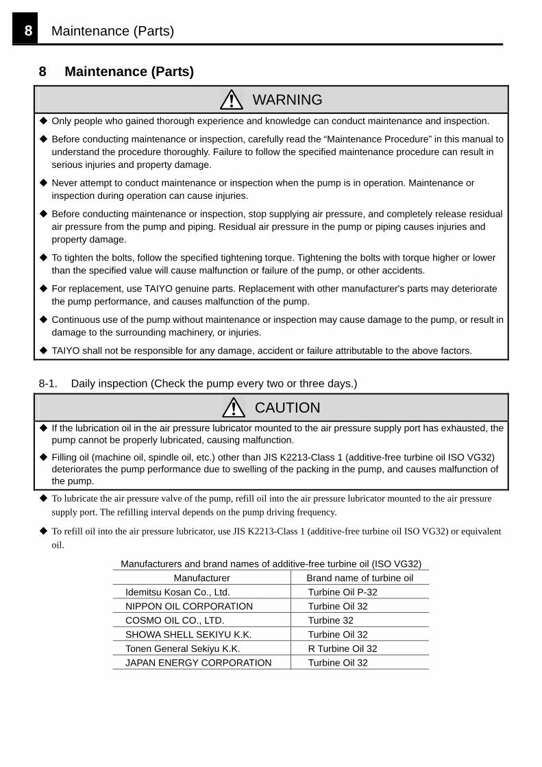
Only people who gained thorough experience and knowledge can conduct maintenance and inspection.
Before conducting maintenance or inspection, carefully read the “Maintenance Procedure” in this manual to understand the procedure thoroughly. Failure to follow the specified maintenance procedure can result in serious injuries and property damage.
Never attempt to conduct maintenance or inspection when the pump is in operation. Maintenance or inspection during operation can cause injuries.
Before conducting maintenance or inspection, stop supplying air pressure, and completely release residual air pressure from the pump and piping. Residual air pressure in the pump or piping causes injuries and property damage.
To tighten the bolts, follow the specified tightening torque. Tightening the bolts with torque higher or lower than the specified value will cause malfunction or failure of the pump, or other accidents.
For replacement, use TAIYO genuine parts. Replacement with other manufacturer's parts may deteriorate the pump performance, and causes malfunction of the pump.
Continuous use of the pump without maintenance or inspection may cause damage to the pump, or result in damage to the surrounding machinery, or injuries.
TAIYO shall not be responsible for any damage, accident or failure attributable to the above factors.
8-1. Daily inspection (Check the pump every two or three days.)
CAUTION
If the lubrication oil in the air pressure lubricator mounted to the air pressure supply port has exhausted, the pump cannot be properly lubricated, causing malfunction.
Filling oil (machine oil, spindle oil, etc.) other than JIS K2213-Class 1 (additive-free turbine oil ISO VG32) deteriorates the pump performance due to swelling of the packing in the pump, and causes malfunction of the pump.
To lubricate the air pressure valve of the pump, refill oil into the air pressure lubricator mounted to the air pressure supply port. The refilling interval depends on the pump driving frequency.
To refill oil into the air pressure lubricator, use JIS K2213-Class 1 (additive-free turbine oil ISO VG32) or equivalent oil.
Manufacturers and brand names of additive-free turbine oil (ISO VG32) Manufacturer Brand name of turbine oil
Idemitsu Kosan Co., Ltd. Turbine Oil P-32 NIPPON OIL CORPORATION Turbine Oil 32 COSMO OIL CO., LTD. Turbine 32 SHOWA SHELL SEKIYU K.K. Turbine Oil 32 Tonen General Sekiyu K.K. R Turbine Oil 32 JAPAN ENERGY CORPORATION Turbine Oil 32
Maintenance (Parts) 9
8-2. Periodic inspection
CAUTION
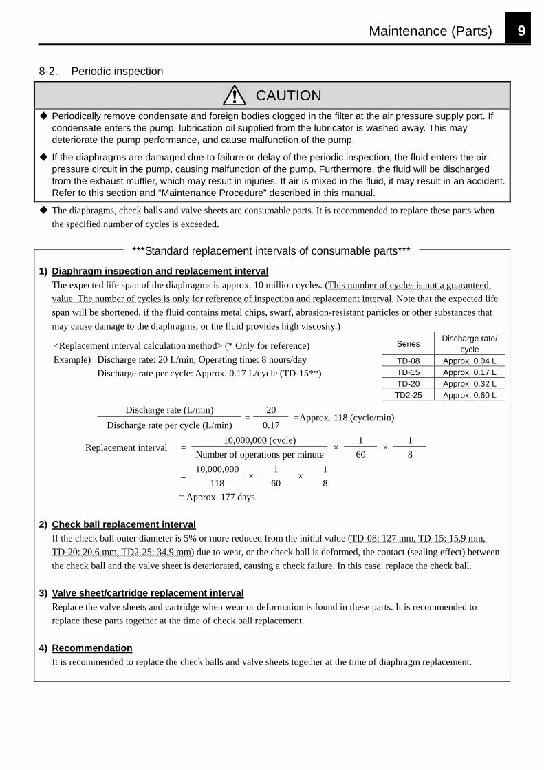
Periodically remove condensate and foreign bodies clogged in the filter at the air pressure supply port. If condensate enters the pump, lubrication oil supplied from the lubricator is washed away. This may deteriorate the pump performance, and cause malfunction of the pump.
If the diaphragms are damaged due to failure or delay of the periodic inspection, the fluid enters the air pressure circuit in the pump, causing malfunction of the pump. Furthermore, the fluid will be discharged from the exhaust muffler, which may result in injuries. If air is mixed in the fluid, it may result in an accident. Refer to this section and “Maintenance Procedure” described in this manual.
The diaphragms, check balls and valve sheets are consumable parts. It is recommended to replace these parts when the specified number of cycles is exceeded.
1) Diaphragm inspec
The expected life spavalue. The number ofspan will be shortenemay cause damage to
<Replacement intervExample) Discharge
Discharge
Di
Discha
Replacemen
2) Check ball replace
If the check ball outeTD-20: 20.6 mm, TDthe check ball and the
3) Valve sheet/cartrid
Replace the valve shereplace these parts to
4) Recommendation
It is recommended to
*
tion and replacement interval n of the diaphragms is approx. 10 million cycles. (This number of cycles is not a guaranteed cycles is only for reference of inspection and replacement interval. Note that the expected life d, if the fluid contains metal chips, swarf, abrasion-resistant particles or other substances that the diaphragms, or the fluid provides high viscosity.)
Series Discharge rate/cycle
TD-08 Approx. 0.04 L TD-15 Approx. 0.17 L TD-20 Approx. 0.32 L
al calculation method> (* Only for reference) rate: 20 L/min, Operating time: 8 hours/day rate per cycle: Approx. 0.17 L/cycle (TD-15**)
TD2-25 Approx. 0.60 L
scharge rate (L/min) 20 rge rate per cycle (L/min)
=0.17
=Approx. 118 (cycle/min)
10,000,000 (cycle) 1 1 t interval =
Number of operations per minute×
60 ×
8 10,000,000 1 1
= 118
×60
×8
= Approx. 177 days
ment interval r diameter is 5% or more reduced from the initial value (TD-08: 127 mm, TD-15: 15.9 mm, 2-25: 34.9 mm) due to wear, or the check ball is deformed, the contact (sealing effect) between valve sheet is deteriorated, causing a check failure. In this case, replace the check ball.
ge replacement interval ets and cartridge when wear or deformation is found in these parts. It is recommended to
gether at the time of check ball replacement.
replace the check balls and valve sheets together at the time of diaphragm replacement.
**Standard replacement intervals of consumable parts***
10 Maintenance Procedure
9 Maintenance Procedure 9-1. Preparations for maintenance
WARNING
Be sure to stop supplying air pressure, release residual air, disconnect the air pressure piping, and make sure that there is no residual pressure in the pump. Residual air pressure in the pump can cause injuries or property damage when the pump is disassembled.
Before disassembly and inspection of the pump, be sure to conduct the following steps: Series
Required toolTD-08 TD-15 TD-20 TD2-25
Box wrench (×1) 10 mm 13 mm 13 mm 13 mm
Discharge all residual fluid from the pump. Stop supplying air pressure, and disconnect the air pressure piping.
Release residual air pressure from the pump. Disconnect the suction and discharge piping. Box wrench (×2) 8 mm 13 mm 17 mm 17 mm
9-2. Check valve disassembly and inspection procedure
(See Figs. 1 and 3.) <*indicates TD2-25 series' parts>
CAUTION
Remove each part carefully to avoid damage to it. Damaged parts deteriorate sealing effect, resulting in remarkable deterioration of the pump performance.
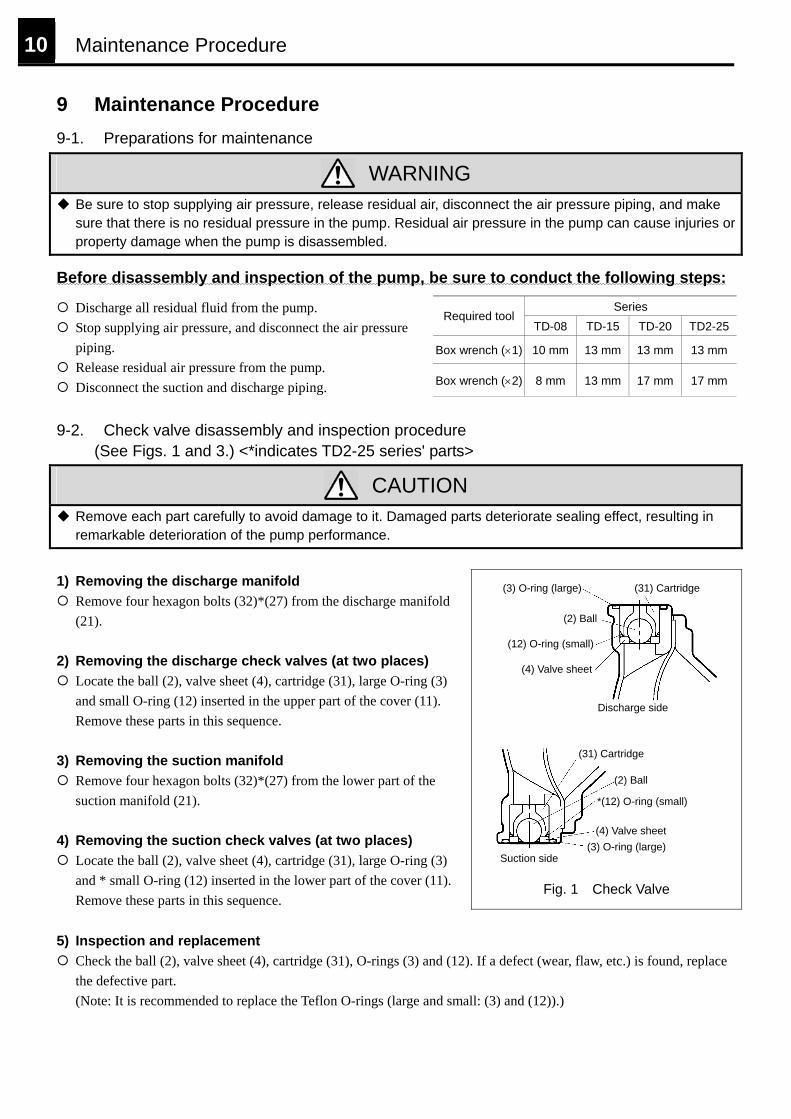
1) Removing the discharge manifold
Remove four hexagon bolts (32)*(27) from the discharge manifold (21).
2) Removing the discharge check valves (at two places)
Locate the ball (2), valve sheet (4), cartridge (31), large O-ring (3) and small O-ring (12) inserted in the upper part of the cover (11). Remove these parts in this sequence.
3) Removing the suction manifold
Remove four hexagon bolts (32)*(27) from the lower part of the suction manifold (21).
4) Removing the suction check valves (at two places)
Locate the ball (2), valve sheet (4), cartridge (31), large O-ring (3) and * small O-ring (12) inserted in the lower part of the cover (11). Remove these parts in this sequence.
Fig. 1 Check Valve
(3) O-ring (large) (31) Cartridge
(2) Ball
(12) O-ring (small)
(4) Valve sheet
Discharge side
(31) Cartridge
(2) Ball
*(12) O-ring (small)
(4) Valve sheet(3) O-ring (large)
Suction side
5) Inspection and replacement
Check the ball (2), valve sheet (4), cartridge (31), O-rings (3) and (12). If a defect (wear, flaw, etc.) is found, replace the defective part. (Note: It is recommended to replace the Teflon O-rings (large and small: (3) and (12)).)
Maintenance Procedure 11
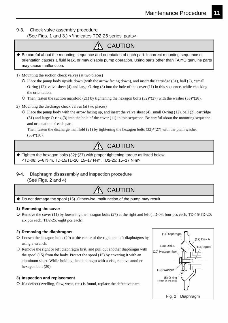
9-3. Check valve assembly procedure (See Figs. 1 and 3.) <*indicates TD2-25 series' parts>
CAUTION
Be careful about the mounting sequence and orientation of each part. Incorrect mounting sequence or orientation causes a fluid leak, or may disable pump operation. Using parts other than TAIYO genuine parts may cause malfunction.
1) Mounting the suction check valves (at two places) Place the pump body upside down (with the arrow facing down), and insert the cartridge (31), ball (2), *small O-ring (12), valve sheet (4) and large O-ring (3) into the hole of the cover (11) in this sequence, while checking the orientation.
Then, fasten the suction manifold (21) by tightening the hexagon bolts (32)*(27) with the washer (33)*(28).
2) Mounting the discharge check valves (at two places) Place the pump body with the arrow facing up, and insert the valve sheet (4), small O-ring (12), ball (2), cartridge (31) and large O-ring (3) into the hole of the cover (11) in this sequence. Be careful about the mounting sequence and orientation of each part. Then, fasten the discharge manifold (21) by tightening the hexagon bolts (32)*(27) with the plain washer (33)*(28).
CAUTION
Tighten the hexagon bolts (32)*(27) with proper tightening torque as listed below: <TD-08: 5–6 N m, TD-15/TD-20: 15–17 N m, TD2-25: 15–17 N m>
9-4. Diaphragm disassembly and inspection procedure
(See Figs. 2 and 4)
CAUTION
Do not damage the spool (15). Otherwise, malfunction of the pump may result.
1) Removing the cover Remove the cover (11) by loosening the hexagon bolts (27) at the right and left (TD-08: four pcs each, TD-15/TD-20: six pcs each, TD2-25: eight pcs each).
2) Removing the diaphragms
Loosen the hexagon bolts (20) at the center of the right and left diaphragms by using a wrench.
Remove the right or left diaphragm first, and pull out another diaphragm with the spool (15) from the body. Protect the spool (15) by covering it with an aluminum sheet. While holding the diaphragm with a vise, remove another hexagon bolt (20).
3) Inspection and replacement
If a defect (swelling, flaw, wear, etc.) is found, replace the defective part.
Fig. 2 Diaphragm
(5) O-ring(Teflon O-ring only)
(18) Disk B
(19) Washer
(20) Hexagon bolt(15) Spool
(1) Diaphragm
(17) Disk A
12 Maintenance Procedure
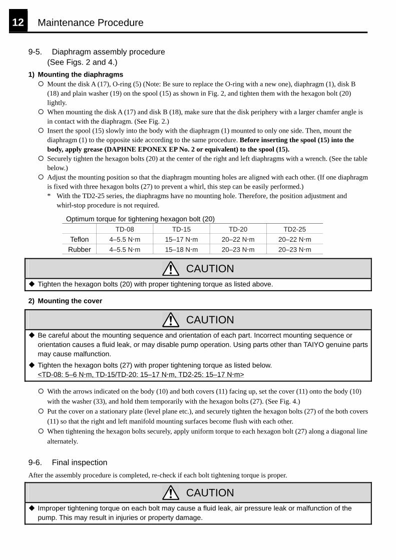
9-5. Diaphragm assembly procedure (See Figs. 2 and 4.)
1) Mounting the diaphragms Mount the disk A (17), O-ring (5) (Note: Be sure to replace the O-ring with a new one), diaphragm (1), disk B (18) and plain washer (19) on the spool (15) as shown in Fig. 2, and tighten them with the hexagon bolt (20) lightly.
When mounting the disk A (17) and disk B (18), make sure that the disk periphery with a larger chamfer angle is in contact with the diaphragm. (See Fig. 2.)
Insert the spool (15) slowly into the body with the diaphragm (1) mounted to only one side. Then, mount the diaphragm (1) to the opposite side according to the same procedure. Before inserting the spool (15) into the body, apply grease (DAPHNE EPONEX EP No. 2 or equivalent) to the spool (15).
Securely tighten the hexagon bolts (20) at the center of the right and left diaphragms with a wrench. (See the table below.)
Adjust the mounting position so that the diaphragm mounting holes are aligned with each other. (If one diaphragm is fixed with three hexagon bolts (27) to prevent a whirl, this step can be easily performed.) * With the TD2-25 series, the diaphragms have no mounting hole. Therefore, the position adjustment and
whirl-stop procedure is not required.
Optimum torque for tightening hexagon bolt (20) TD-08 TD-15 TD-20 TD2-25
Teflon 4–5.5 N m 15–17 N m 20–22 N m 20–22 N m Rubber 4–5.5 N m 15–18 N m 20–23 N m 20–23 N m
CAUTION
Tighten the hexagon bolts (20) with proper tightening torque as listed above.
2) Mounting the cover
CAUTION
Be careful about the mounting sequence and orientation of each part. Incorrect mounting sequence or orientation causes a fluid leak, or may disable pump operation. Using parts other than TAIYO genuine parts may cause malfunction.
Tighten the hexagon bolts (27) with proper tightening torque as listed below. <TD-08: 5–6 N m, TD-15/TD-20: 15–17 N m, TD2-25: 15–17 N m>
With the arrows indicated on the body (10) and both covers (11) facing up, set the cover (11) onto the body (10) with the washer (33), and hold them temporarily with the hexagon bolts (27). (See Fig. 4.)
Put the cover on a stationary plate (level plane etc.), and securely tighten the hexagon bolts (27) of the both covers (11) so that the right and left manifold mounting surfaces become flush with each other.
When tightening the hexagon bolts securely, apply uniform torque to each hexagon bolt (27) along a diagonal line alternately.
9-6. Final inspection After the assembly procedure is completed, re-check if each bolt tightening torque is proper.
CAUTION
Improper tightening torque on each bolt may cause a fluid leak, air pressure leak or malfunction of the pump. This may result in injuries or property damage.
Maintenance Procedure 13
(23) Mounting foot
(33) *(28) Washer
(32) *(27) Hexagon bolt
(21) Manifold (Suction side)
(4) Valve sheet
(3) O-ring (large)
*(12) O-ring (small)
(2) Ball
(31) Cartridge
(10) Body
(28) Washer
Arrow
(27) Hexagon bolt
(11) Cover
(26) Air valve
(4) Valve sheet
(2) Ball
(12) O-ring (small)
(31) Cartridge
(3) O-ring (large)
(21) Manifold (Discharge side)
(33) *(28) Washer
(32) *(27) Hexagon bolt
(22) Plug
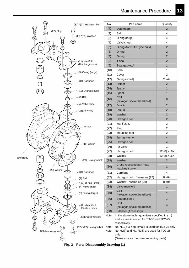
No. Part name Quantity (1) Diaphragm 2 (2) Ball 4 (3) O-ring (large) 4 (4) Valve sheet 4 (5) O-ring (for PTFE type only) 2 (6) O-ring 2 (7) O-ring 2 (8) T-seal 2 (9) Seat gasket A 1
(10) Body 1 (11) Cover 2 (12) O-ring (small) 2 <4> (13) Holder 2 (14) Spacer 1 (15) Spool 1
(16) CBT (hexagon socket head bolt) 8
(17) Disk A 2 (18) Disk B 2 (19) Washer 2 (20) Hexagon bolt 2 (21) Manifold D 2 (22) Plug 2 (23) Mounting foot 2 (24) Spring washer 4 (25) Hexagon bolt 4 (26) Air valve 1 (27) Hexagon bolt 12 (8) <16> (28) Washer 12 (8) <16> (29) Washer 2
(30) Cross-recessed pan head machine screw 2
(31) Cartridge 4 (32) Hexagon bolt *same as (27) 8 <0> (33) Washer *same as (28) 8 <0> (34) Valve manifold 1
(35) CBT (hexagon socket head bolt) 4
(36) Seat gasket B 1
(37) CBT (hexagon socket head bolt) 4
(38) Silencer (Accessory) 1 Note: In the above table, quantities specified in ( )
and < > are intended for TD-08 and TD2-25, respectively.
Note: No. *(12): O-ring (small) is used for TD2-25 only.Note: No. *(27) and No. *(28) are used for TD2-25
only. (Same size as the cover mounting parts)
Fig. 3 Parts Disassembly Drawing (1)
14 Maintenance Procedure
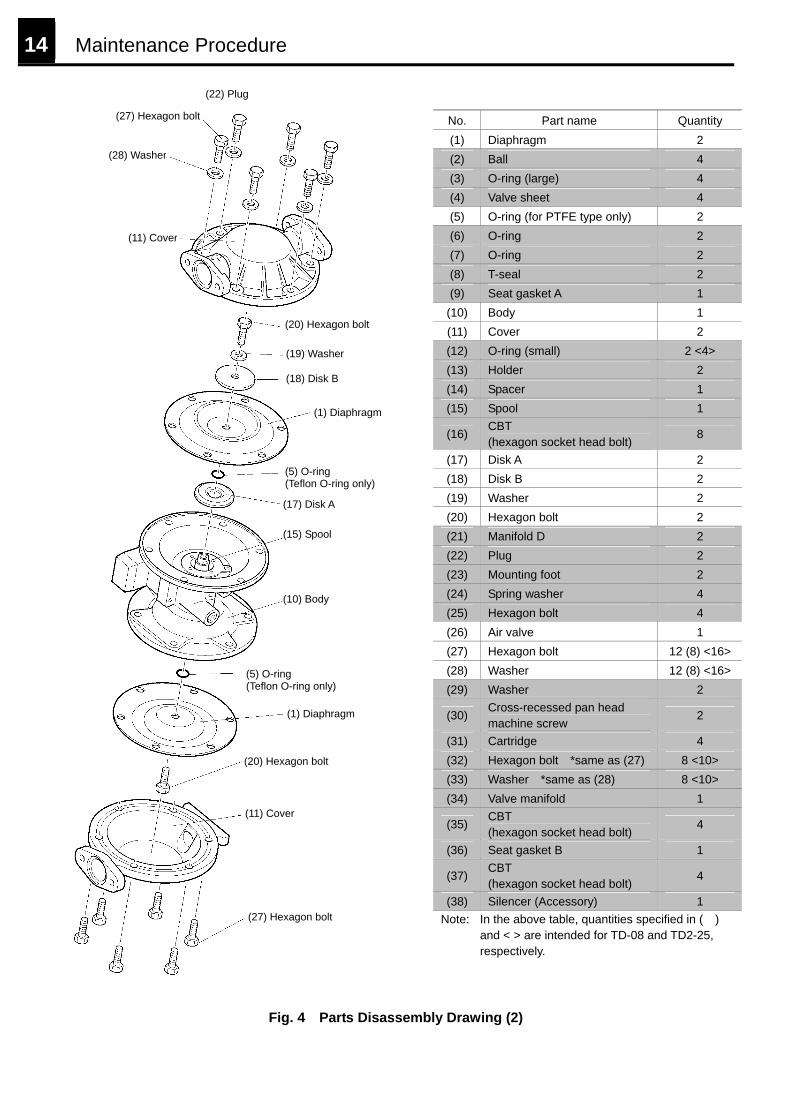
(22) Plug
(27) Hexagon bolt
(11) Cover
(20) Hexagon bolt
(1) Diaphragm
(5) O-ring (Teflon O-ring only)
(10) Body
(15) Spool
(17) Disk A
(5) O-ring (Teflon O-ring only)
(1) Diaphragm
(18) Disk B
(19) Washer
(20) Hexagon bolt
(28) Washer
(27) Hexagon bolt
(11) Cover
No. Part name Quantity (1) Diaphragm 2 (2) Ball 4 (3) O-ring (large) 4 (4) Valve sheet 4 (5) O-ring (for PTFE type only) 2 (6) O-ring 2 (7) O-ring 2 (8) T-seal 2 (9) Seat gasket A 1
(10) Body 1 (11) Cover 2 (12) O-ring (small) 2 <4> (13) Holder 2 (14) Spacer 1 (15) Spool 1
(16) CBT (hexagon socket head bolt) 8
(17) Disk A 2 (18) Disk B 2 (19) Washer 2 (20) Hexagon bolt 2 (21) Manifold D 2 (22) Plug 2 (23) Mounting foot 2 (24) Spring washer 4 (25) Hexagon bolt 4 (26) Air valve 1 (27) Hexagon bolt 12 (8) <16>(28) Washer 12 (8) <16>(29) Washer 2
(30) Cross-recessed pan head machine screw 2
(31) Cartridge 4 (32) Hexagon bolt *same as (27) 8 <10> (33) Washer *same as (28) 8 <10> (34) Valve manifold 1
(35) CBT (hexagon socket head bolt) 4
(36) Seat gasket B 1
(37) CBT (hexagon socket head bolt) 4
(38) Silencer (Accessory) 1 Note: In the above table, quantities specified in ( )
and < > are intended for TD-08 and TD2-25, respectively.
Fig. 4 Parts Disassembly Drawing (2)

Major Dimensions/Terminology/Warranty 15
10 Major Dimensions
Series Max. discharge rate
Pump bore diameter
Air pressure connection bore
diameter
Tolerance of solid body in fluid Body material Diaphragm and ball materials
TD-08 13 L/min Rc1/4 Rc1/4 φ1 mm or less
TD-15 35 L/min Rc1/2 Rc1/4 φ2 mm or less
TD-20 54 L/min Rc3/4 Rc1/4 φ2 mm or less
Nitrile rubber - Polyacetal PTFE-PTFE
Chloroprene rubber - Polyacetal Fluoro rubber - Fluoro rubber
Ethylenepropylene rubber - Polyacetal Nitrile rubber - Urethane rubber
TD2-25 160 L/min Rc1 Rc3/8 φ3 mm or less Alum
inum
allo
y
Stai
nles
s st
eel
Nitrile rubber - Nitrile rubber PTFE - PTFE
Nitrile rubber - Urethane rubber
Operating air pressure is 0.2 to 0.7 MPa. Maximum operating viscosity is 3000 mPa s. Operating temperature range (Operating fluid temperature and ambient temperature) is 0 to 60°C. (No freezing)
11 Terminology Cavitation: A phenomenon that generates a cavity near a fluid cross section or flow direction changing point, which results in an eddy current. Cavitation causes vibration, noise and damage to the blades and the pump.
12 Warranty 12-1. Warranty period Warranty period shall be 12 months from the date of product delivery.
12-2. Scope of warranty If a defect in the materials of genuine components of this product, or a manufacturing failure is found within the warranty period, and TAIYO recognizes it, such a defect or failure shall be repaired free of charge.
12-3. Exemption from scope of warranty Even within the warranty period, a defect or failure attributable to any of the following factors shall be out of the scope of warranty. (1) A failure attributable to improper use or handling of the product, or improper storage and maintenance of the
product (2) A failure attributable to use of compressed air that contains impurities or too much condensate as driving force, or
use of a gas or liquid other than air as driving force (3) A failure attributable to use of any part other than TAIYO genuine parts (4) A failure attributable to use of a fluid that may cause corrosion, swelling or dissolution of the product components (5) Repair conducted by any person other than TAIYO personnel (6) A failure attributable to modification of the product made by any person other than TAIYO personnel (7) A failure attributable to use of a fluid with excessive abrasive characteristic or a fluid incompatible with this product (8) Wear of consumable parts (diaphragms, balls, valve sheets, etc.) 12-4. Repair parts Repair parts shall be retained for three years after discontinuation of production. In some cases, however, parts that passed one year or longer after discontinuation of production may not be supplied. If you have any inconvenience or question about this product, contact the pump distributor, or TAIYO sales office or contact center. E-mail: [email protected] Tel: +81-6-6340-1108 Fax: +81-6-6340-1134