Embed Size (px)
Citation preview

PROGRAMMING CONTROLS OPERATING CONTROLS
CONTROL MODE
START / ADVANCEDISPLAY
CONTROL
OFF
A B C D E F M1 M2
MANUAL LOCAL MAXI
CANCEL / CLEAR
SCHEDULE
STATION RUN TIMES
START TIMES
START DAYS
WATER BUDGET
WEEKDAY / CYCLE
CLOCK STATUS
SCHEDULE MONITOR
MULTI-MANUAL
SET CLOCK
SYSTEM INFORMATION
COPY STORE
COPY PASTE
PAR+ES ControllerOperation Manual
P/N: 635777-01
635777 Rev B (PAR+ES operations manual (1of2 ENG)) source.indd 1 12/20/2007 8:40:17 AM
Contents
Introduction ��������������������������������������������� 1
Welcome to Rain Bird �������������������������������������������������� 1
Controls and Indicators ���������������������������������������������� 1
Programming the Controller ������������������ 3
Programming Checklist ���������������������������������������������� 3
Power-up the Controller ��������������������������������������������� 4
Clock Status Mode �������������������������������������������������������� 4
Control Modes ��������������������������������������������������������������� 5
Set the Clock (Day & Time) ����������������������������������������� 6
Select Start Day Method �������������������������������������������� 6
Set Watering Start Days ���������������������������������������������� 7
Set Schedule Start Time(s) ����������������������������������������� 9
Set Station Run Times ������������������������������������������������10
Optional Station Switches ���������������������������������������11
Controller Operation ����������������������������� 12
Set Water Budget ��������������������������������������������������������12
Schedule Monitor �������������������������������������������������������13
Manual Operation �������������������������������������������������������14
Special Controller Functions ����������������� 16
System Information ����������������������������������������������������16
Station Limit ������������������������������������������������������������������19
Decoder Controller Setup ��������������������� 20
Decoder Menu �������������������������������������������������������������20
Circuit Breaker Tripped Mode ���������������������������������30
Adjust LCD Display Brightness �������������������������������30
PAR+ES ControllerOperation Manual
635777 Rev B (PAR+ES operations manual (1of2 ENG)) source.indd 2 12/20/2007 8:40:17 AM
PAR+ES Operation Manual 1
PROGRAMMING CONTROLS OPERATING CONTROLS
CONTROL MODE
START / ADVANCEDISPLAY
CONTROL
OFF
A B C D E F M1 M2
MANUAL LOCAL MAXI
CANCEL / CLEAR
SCHEDULE
STATION RUN TIMES
START TIMES
START DAYS
WATER BUDGET
WEEKDAY / CYCLE
CLOCK STATUS
SCHEDULE MONITOR
MULTI-MANUAL
SET CLOCK
SYSTEM INFORMATION
COPY STORE
COPY PASTE
IntroductionWelcome to Rain BirdCongratulations on purchasing a Rain Bird PAR+ES irrigation controller� The PAR+ES controller electrically controls up to 72 watering stations� Each station can control from one to four valves (except for Decoder Controllers where the maximum number of valves per station is 2, depending on the decoder type)�
The PAR+ES lets you program six different watering schedules (A, B, C, D, E, and F) for automatic operation� Schedules A through F operate their assigned stations in numerical order� Each schedule can have up to 12 start times per day�
The PAR+ES also has two Manual schedules (M1 and M2) that offer additional convenience and watering flexibility�
All eight PAR+ES schedules can run simultaneously, but a maximum of sixteen (16) valves (including a master valve) can operate at one time�
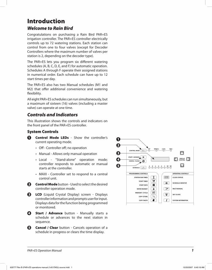
Controls and IndicatorsThis illustration shows the controls and indicators on the front panel of the PAR+ES controller�
System ControlsControl Mode LEDs1. - Show the controller’s current operating mode�
Off - Controller off; no operation•
Manual - Allows only manual operation•
Local - “Stand-alone” operation mode; •controller responds to automatic or manual starts at the controller�
MAXI - Controller set to respond to a central •control unit�
Control Mode2. button - Used to select the desired controller operation mode�
LCD3. (Liquid Crystal Display) screen - Displays controller information and prompts user for input� Displays data for the function being programmed or monitored�
Start / Advance4. button - Manually starts a schedule or advances to the next station in sequence�
Cancel / Clear5. button - Cancels operation of a schedule in progress or clears the time display�
2
1
3
4
5
635777 Rev B (PAR+ES operations manual (1of2 ENG)) source.indd 1 12/20/2007 8:40:18 AM
PAR+ES Operation Manual2
CONTROL MODE
START / ADVANCEDISPLAY
CONTROL
OFF
A B C D E F M1 M2
MANUAL LOCAL MAXI
CANCEL / CLEAR
SCHEDULE
PROGRAMMING CONTROLS OPERATING CONTROLS
STATION RUN TIMES
START TIMES
START DAYS
WATER BUDGET
WEEKDAY / CYCLE
CLOCK STATUS
SCHEDULE MONITOR
MULTI-MANUAL
SET CLOCK
SYSTEM INFORMATION
COPY STORE
COPY PASTE
PROGRAMMING CONTROLS OPERATING CONTROLS
STATION RUN TIMES
START TIMES
START DAYS
WATER BUDGET
WEEKDAY / CYCLE
CLOCK STATUS
SCHEDULE MONITOR
MULTI-MANUAL
SET CLOCK
SYSTEM INFORMATION
COPY STORE
COPY PASTE
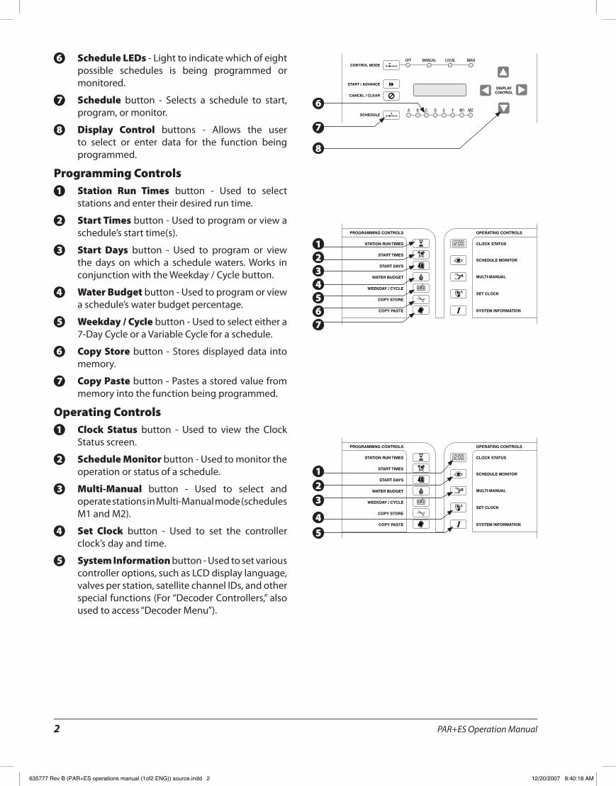
Schedule LEDs6. - Light to indicate which of eight possible schedules is being programmed or monitored�
Schedule7. button - Selects a schedule to start, program, or monitor�
Display Control8. buttons - Allows the user to select or enter data for the function being programmed�
Programming ControlsStation Run Times1. button - Used to select stations and enter their desired run time�
Start Times2. button - Used to program or view a schedule’s start time(s)�
Start Days3. button - Used to program or view the days on which a schedule waters� Works in conjunction with the Weekday / Cycle button�
Water Budget4. button - Used to program or view a schedule’s water budget percentage�
Weekday / Cycle5. button - Used to select either a 7-Day Cycle or a Variable Cycle for a schedule�
Copy Store6. button - Stores displayed data into memory�
Copy Paste7. button - Pastes a stored value from memory into the function being programmed�
Operating ControlsClock Status1. button - Used to view the Clock Status screen�
Schedule Monitor2. button - Used to monitor the operation or status of a schedule�
Multi-Manual3. button - Used to select and operate stations in Multi-Manual mode (schedules M1 and M2)�
Set Clock4. button - Used to set the controller clock’s day and time�
System Information5. button - Used to set various controller options, such as LCD display language, valves per station, satellite channel IDs, and other special functions (For “Decoder Controllers,” also used to access “Decoder Menu”)�
7
6
8
1234567
123
4
5
635777 Rev B (PAR+ES operations manual (1of2 ENG)) source.indd 2 12/20/2007 8:40:18 AM
PAR+ES Operation Manual 3
Programming the ControllerThe PAR+ES controller offers six automatic watering schedules (A through F)� The PAR+ES also has two Manual schedules (M1 and M2) that can be manually started at any time�
These schedules let you customize your watering to meet the needs of different types of plants, soil conditions, slopes, sunny or shady areas, watering windows, etc�
Programming is the process of telling the controller exactly when and how long you want to water� The controller opens and closes each station’s remote control valves according to the information you program into each schedule�
You will need to understand the following terms to successfully program your PAR+ES controller�
Watering day cycle• - The period of days in which the controller repeats the watering schedule you set� The PAR+ES offers two different watering day cycles:
Variable methodI� - Waters on a daily interval from one to nine days (e�g�, every third day, every fifth day, etc�) Watering always occurs on the last day of the selected watering cycle�
7 Day Week methodII� - Waters on the days of the week you select� A 7 Day Week cycle lets you set a custom watering cycle in which any day(s) of the week can be a watering day�
Watering days• - The specific days of the week when watering takes place�
Start time(s)• - The time(s) of day that the schedule begins� This is the time the first station in the schedule begins watering; all other stations then follow in sequence�
NOTE: ! The term “start time” refers to the time that the schedule starts, not to the time that each individual station begins to run�
Run time• - The number of minutes (or hours and minutes) that each station runs�
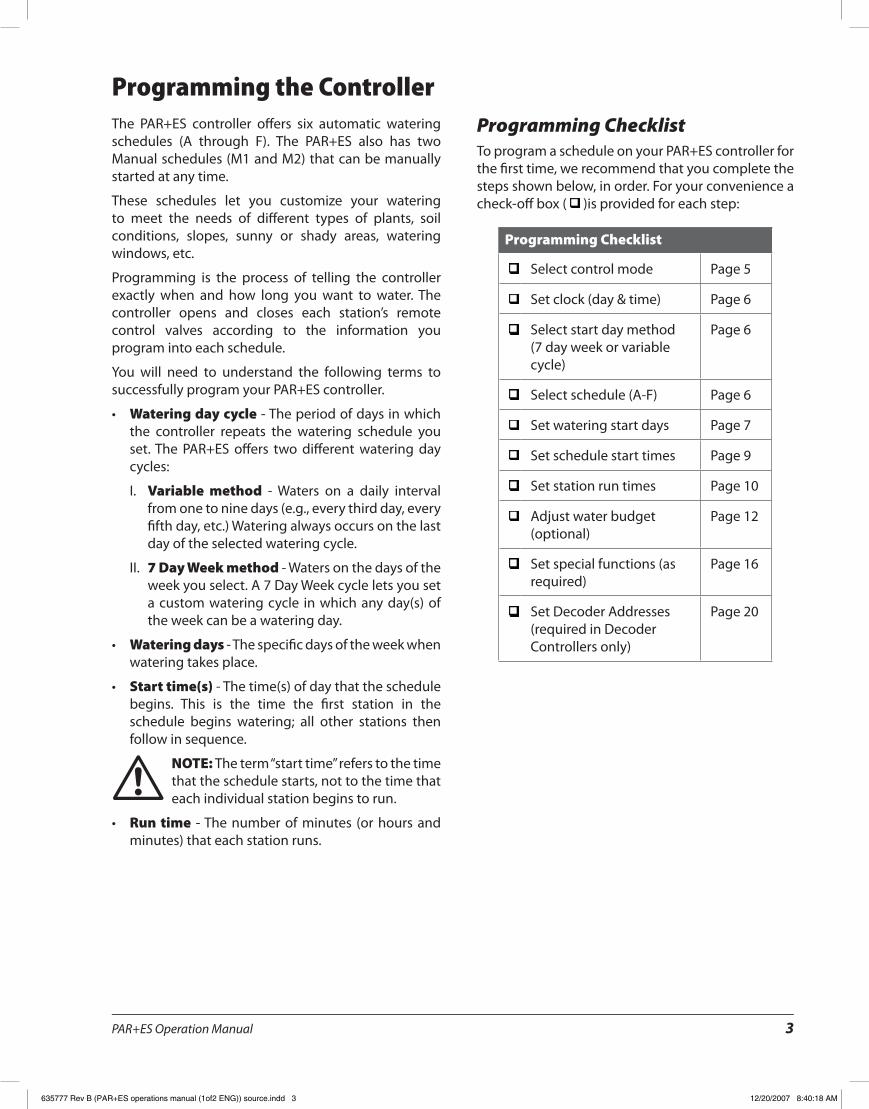
Programming ChecklistTo program a schedule on your PAR+ES controller for the first time, we recommend that you complete the steps shown below, in order� For your convenience a check-off box ( )is provided for each step:
Programming Checklist
Select control mode Page 5
Set clock (day & time) Page 6
Select start day method (7 day week or variable cycle)
Page 6
Select schedule (A-F) Page 6
Set watering start days Page 7
Set schedule start times Page 9
Set station run times Page 10
Adjust water budget (optional)
Page 12
Set special functions (as required)
Page 16
Set Decoder Addresses (required in Decoder Controllers only)
Page 20
635777 Rev B (PAR+ES operations manual (1of2 ENG)) source.indd 3 12/20/2007 8:40:18 AM
PAR+ES Operation Manual4
OFF ON
DISPLAYCONTROL
PROGRAMMING CONTROLS OPERATING CONTROLS
CONTROL MODE
START / ADVANCEDISPLAY
CONTROL
OFF
A B C D E F M1 M2
MANUAL LOCAL MAXI
CANCEL / CLEAR
SCHEDULE
STATION RUN TIMES
START TIMES
START DAYS
WATER BUDGET
WEEKDAY / CYCLE
CLOCK STATUS
SCHEDULE MONITOR
MULTI-MANUAL
SET CLOCK
SYSTEM INFORMATION
COPY STORE
COPY PASTE
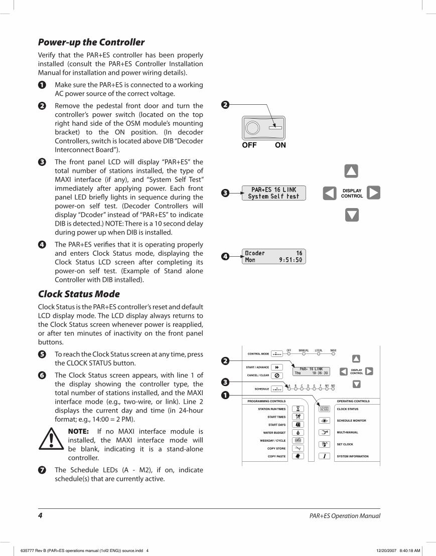
Power-up the ControllerVerify that the PAR+ES controller has been properly installed (consult the PAR+ES Controller Installation Manual for installation and power wiring details)�
Make sure the PAR+ES is connected to a working 1.AC power source of the correct voltage�
Remove the pedestal front door and turn the 2.controller’s power switch (located on the top right hand side of the OSM module’s mounting bracket) to the ON position� (In decoder Controllers, switch is located above DIB “Decoder Interconnect Board”)�
The front panel LCD will display “PAR+ES” the 3.total number of stations installed, the type of MAXI interface (if any), and “System Self Test” immediately after applying power� Each front panel LED briefly lights in sequence during the power-on self test� (Decoder Controllers will display “Dcoder” instead of “PAR+ES” to indicate DIB is detected�) NOTE: There is a 10 second delay during power up when DIB is installed�
The PAR+ES verifies that it is operating properly 4.and enters Clock Status mode, displaying the Clock Status LCD screen after completing its power-on self test� (Example of Stand alone Controller with DIB installed)�
Clock Status ModeClock Status is the PAR+ES controller’s reset and default LCD display mode� The LCD display always returns to the Clock Status screen whenever power is reapplied, or after ten minutes of inactivity on the front panel buttons�
To reach the Clock Status screen at any time, press 5.the CLOCK STATUS button�
The Clock Status screen appears, with line 1 of 6.the display showing the controller type, the total number of stations installed, and the MAXI interface mode (e�g�, two-wire, or link)� Line 2 displays the current day and time (in 24-hour format; e�g�, 14:00 = 2 PM)�
NOTE: ! If no MAXI interface module is installed, the MAXI interface mode will be blank, indicating it is a stand-alone controller�
The Schedule LEDs (A - M2), if on, indicate 7.schedule(s) that are currently active�
PAR+ES 16 LINKSystem Self test
Dcoder 16Mon 9:51:50
PAR+ 16 LINKThu 10:36:30
2
3
4
1
2
3
635777 Rev B (PAR+ES operations manual (1of2 ENG)) source.indd 4 12/20/2007 8:40:18 AM
PAR+ES Operation Manual 5
CONTROL MODE
START / ADVANCEDISPLAY
CONTROL
OFF
A B C D E F M1 M2
MANUAL LOCAL MAXI
CANCEL / CLEAR
SCHEDULE
CONTROL MODE
START / ADVANCEDISPLAY
CONTROL
OFF
A B C D E F M1 M2
MANUAL LOCAL MAXI
CANCEL / CLEAR
SCHEDULE
CONTROL MODE
START / ADVANCEDISPLAY
CONTROL
OFF
A B C D E F M1 M2
MANUAL LOCAL MAXI
CANCEL / CLEAR
SCHEDULE
CONTROL MODE
START / ADVANCEDISPLAY
CONTROL
OFF
A B C D E F M1 M2
MANUAL LOCAL MAXI
CANCEL / CLEAR
SCHEDULE
CONTROL MODE
START / ADVANCEDISPLAY
CONTROL
OFF
A B C D E F M1 M2
MANUAL LOCAL MAXI
CANCEL / CLEAR
SCHEDULE
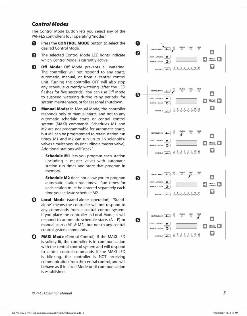
Control ModesThe Control Mode button lets you select any of the PAR+ES controller’s four operating “modes�”
Press the 1. CONTROL MODE button to select the desired Control Mode�
The selected Control Mode LED lights indicate 2.which Control Mode is currently active�
Off Mode:3. Off Mode prevents all watering� The controller will not respond to any starts; automatic, manual, or from a central control unit� Turning the controller OFF will also stop any schedule currently watering (after the LED flashes for five seconds)� You can use Off Mode to suspend watering during rainy periods, for system maintenance, or for seasonal shutdown�
Manual Mode:4. In Manual Mode, the controller responds only to manual starts, and not to any automatic schedule starts or central control system (MAXI) commands� Schedules M1 and M2 are not programmable for automatic starts, but M1 can be programmed to retain station run times� M1 and M2 can run up to 16 solenoids/valves simultaneously (including a master valve)� Additional stations will “stack�”
Schedule M1• lets you program each station (including a master valve) with automatic station run times and store that program in memory�
Schedule M2• does not allow you to program automatic station run times� Run times for each station must be entered separately each time you activate schedule M2�
Local Mode5. (stand-alone operation): “Stand-alone” means the controller will not respond to any commands from a central control system� If you place the controller in Local Mode, it will respond to automatic schedule starts (A - F) or manual starts (M1 & M2), but not to any central control system commands�
MAXI Mode6. (Central Control): If the MAXI LED is solidly lit, the controller is in communication with the central control system and will respond to central control commands� If the MAXI LED is blinking, the controller is NOT receiving communication from the central control, and will behave as if in Local Mode until communication is established�
1
2
4
5
6
3
635777 Rev B (PAR+ES operations manual (1of2 ENG)) source.indd 5 12/20/2007 8:40:18 AM
PAR+ES Operation Manual6
PROGRAMMING CONTROLS OPERATING CONTROLS
STATION RUN TIMES
START TIMES
START DAYS
WATER BUDGET
WEEKDAY / CYCLE
CLOCK STATUS
SCHEDULE MONITOR
MULTI-MANUAL
SET CLOCK
SYSTEM INFORMATION
COPY STORE
COPY PASTE
DISPLAYCONTROL
DISPLAYCONTROL
CONTROL MODE
START / ADVANCEDISPLAY
CONTROL
OFF
A B C D E F M1 M2
MANUAL LOCAL MAXI
CANCEL / CLEAR
SCHEDULE
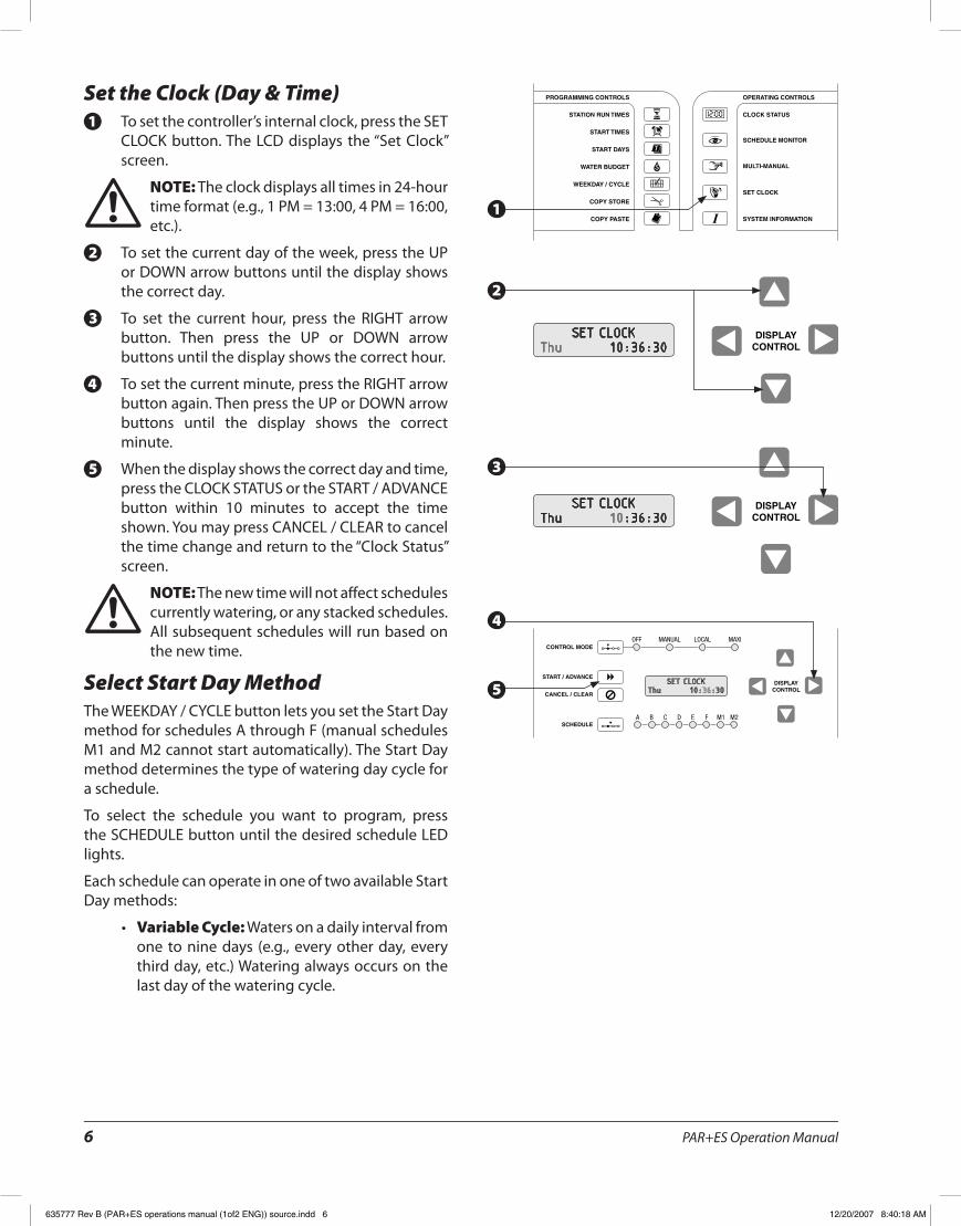
Set the Clock (Day & Time)To set the controller’s internal clock, press the SET 1.CLOCK button� The LCD displays the “Set Clock” screen�
NOTE: ! The clock displays all times in 24-hour time format (e�g�, 1 PM = 13:00, 4 PM = 16:00, etc�)�
To set the current day of the week, press the UP 2.or DOWN arrow buttons until the display shows the correct day�
To set the current hour, press the RIGHT arrow 3.button� Then press the UP or DOWN arrow buttons until the display shows the correct hour�
To set the current minute, press the RIGHT arrow 4.button again� Then press the UP or DOWN arrow buttons until the display shows the correct minute�
When the display shows the correct day and time, 5.press the CLOCK STATUS or the START / ADVANCE button within 10 minutes to accept the time shown� You may press CANCEL / CLEAR to cancel the time change and return to the “Clock Status” screen�
NOTE: ! The new time will not affect schedules currently watering, or any stacked schedules� All subsequent schedules will run based on the new time�
Select Start Day MethodThe WEEKDAY / CYCLE button lets you set the Start Day method for schedules A through F (manual schedules M1 and M2 cannot start automatically)� The Start Day method determines the type of watering day cycle for a schedule�
To select the schedule you want to program, press the SCHEDULE button until the desired schedule LED lights�
Each schedule can operate in one of two available Start Day methods:
Variable Cycle:• Waters on a daily interval from one to nine days (e�g�, every other day, every third day, etc�) Watering always occurs on the last day of the watering cycle�
SET CLOCKThu 10:36:30
SET CLOCKThu 10:36:30
SET CLOCKThu 10:36:30
1
2
4
5
3
635777 Rev B (PAR+ES operations manual (1of2 ENG)) source.indd 6 12/20/2007 8:40:18 AM

PAR+ES Operation Manual 7
PROGRAMMING CONTROLS OPERATING CONTROLS
STATION RUN TIMES
START TIMES
START DAYS
WATER BUDGET
WEEKDAY / CYCLE
CLOCK STATUS
SCHEDULE MONITOR
MULTI-MANUAL
SET CLOCK
SYSTEM INFORMATION
COPY STORE
COPY PASTE
DISPLAYCONTROL
DISPLAYCONTROL
DISPLAYCONTROL
PROGRAMMING CONTROLS OPERATING CONTROLS
A B C D E F M1 M2SCHEDULE
STATION RUN TIMES
START TIMES
START DAYS
WATER BUDGET
WEEKDAY / CYCLE
CLOCK STATUS
SCHEDULE MONITOR
MULTI-MANUAL
SET CLOCK
SYSTEM INFORMATION
COPY STORE
COPY PASTE
7-Day Week Cycle:• Waters on the days of the week you select� A 7-Day Week Cycle allows you to set a custom watering cycle in which any day of the week can be a watering day (For example, Monday, Wednesday, Friday, or Tuesday, Thursday, Saturday, etc�)�
To select a Start Day method, press the WEEKDAY 1./ CYCLE button� The Schedule A LED lights� Press the SCHEDULE button if you want to program a different schedule�
With the desired schedule displayed, press the UP 2./ DOWN arrow buttons until the desired Start Day method (Variable Cycle or 7 Day Week) appears in the display� You can now program watering days for the selected schedule according to the Start Day method you selected�
Set Watering Start DaysThe Start Days function selects the days on which a schedule will water� If you selected the 7-Day Week Cycle, you may choose any or all days within the week� If you selected the Variable Cycle, the schedule will water every day, every other day, etc�; up to every ninth day� Follow the procedure for the Start Day method you selected�
7-Day Week MethodPress the START DAYS button� The Schedule A 1.LED lights� To select a different schedule, press the SCHEDULE button�
The display shows the active days of the week 2.(days when irrigation occurs)� Line 1 of the display alternates between listing the screen title, and stating whether the selected day is ON or OFF� In line 2 of the display, the cursor shows which day of the week is selected� When a day is turned OFF, that day no longer appears in line 2�
Press the LEFT / RIGHT arrow buttons and the 3.cursor will scroll from Sunday through Saturday�
Press the UP / DOWN arrow buttons to turn each 4.day of the week ON or OFF�
START DAY METHOD* 7 Day Week *
START WEEK DAYSSun T W T F Sa
Monday is OFFSun T W T F Sa
1
2
1
2
4
3
635777 Rev B (PAR+ES operations manual (1of2 ENG)) source.indd 7 12/20/2007 8:40:18 AM
PAR+ES Operation Manual8
PROGRAMMING CONTROLS OPERATING CONTROLS
A B C D E F M1 M2SCHEDULE
STATION RUN TIMES
START TIMES
START DAYS
WATER BUDGET
WEEKDAY / CYCLE
CLOCK STATUS
SCHEDULE MONITOR
MULTI-MANUAL
SET CLOCK
SYSTEM INFORMATION
COPY STORE
COPY PASTE
PROGRAMMING CONTROLS OPERATING CONTROLS
A B C D E F M1 M2SCHEDULE
STATION RUN TIMES
START TIMES
START DAYS
WATER BUDGET
WEEKDAY / CYCLE
CLOCK STATUS
SCHEDULE MONITOR
MULTI-MANUAL
SET CLOCK
SYSTEM INFORMATION
COPY STORE
COPY PASTE
DISPLAYCONTROL
DISPLAYCONTROL
PROGRAMMING CONTROLS OPERATING CONTROLS
A B C D E F M1 M2SCHEDULE
STATION RUN TIMES
START TIMES
START DAYS
WATER BUDGET
WEEKDAY / CYCLE
CLOCK STATUS
SCHEDULE MONITOR
MULTI-MANUAL
SET CLOCK
SYSTEM INFORMATION
COPY STORE
COPY PASTE
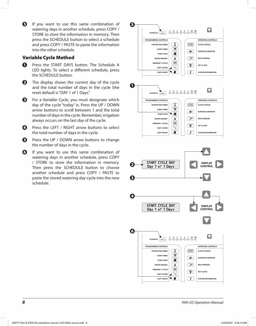
If you want to use this same combination of 5.watering days in another schedule, press COPY / STORE to store the information in memory� Then press the SCHEDULE button to select a schedule and press COPY / PASTE to paste the information into the other schedule�
Variable Cycle MethodPress the START DAYS button� The Schedule A 1.LED lights� To select a different schedule, press the SCHEDULE button�
The display shows the current day of the cycle 2.and the total number of days in the cycle (the reset default is “DAY 1 of 1 Days�”
For a Variable Cycle, you must designate which 3.day of the cycle “today” is� Press the UP / DOWN arrow buttons to scroll between 1 and the total number of days in the cycle� Remember, irrigation always occurs on the last day of the cycle�
Press the LEFT / RIGHT arrow buttons to select 4.the total number of days in the cycle�
Press the UP / DOWN arrow buttons to change 5.the number of days in the cycle�
If you want to use this same combination of 6.watering days in another schedule, press COPY / STORE to store the information in memory� Then press the SCHEDULE button to choose another schedule and press COPY / PASTE to paste the stored watering day cycle into the new schedule�
START CYCLE DAYDay 1 of 1 Days
START CYCLE DAYDay 1 of 1 Days
5
1
3
2
4
6
635777 Rev B (PAR+ES operations manual (1of2 ENG)) source.indd 8 12/20/2007 8:40:19 AM

PAR+ES Operation Manual 9
PROGRAMMING CONTROLS OPERATING CONTROLS
A B C D E F M1 M2SCHEDULE
STATION RUN TIMES
START TIMES
START DAYS
WATER BUDGET
WEEKDAY / CYCLE
CLOCK STATUS
SCHEDULE MONITOR
MULTI-MANUAL
SET CLOCK
SYSTEM INFORMATION
COPY STORE
COPY PASTE
DISPLAYCONTROL
DISPLAYCONTROL
PROGRAMMING CONTROLS OPERATING CONTROLS
A B C D E F M1 M2SCHEDULE
STATION RUN TIMES
START TIMES
START DAYS
WATER BUDGET
WEEKDAY / CYCLE
CLOCK STATUS
SCHEDULE MONITOR
MULTI-MANUAL
SET CLOCK
SYSTEM INFORMATION
COPY STORE
COPY PASTE
Set Schedule Start Time(s)The start time determines when each schedule begins watering� You may assign up to 12 start times per day to schedules A through F (manual schedules M1 and M2 do not accept automatic start times)�
Multiple start times let you run a schedule more than once each day� For example, in an area with a steep slope, you may use several starts per day with short station run times to help prevent runoff and lessen erosion�
If the start time of one schedule overlaps an active (currently watering) schedule, the second schedule will be “stacked” to begin watering as soon as the first schedule finishes�
NOTE: ! The PAR+ES controller always places start times in chronological order (from earliest to latest), regardless of the order they were entered�
To enter a start time for a schedule, press the 1.START TIMES button� The Schedule A LED lights� To select a different schedule, press the SCHEDULE button�
If no start times are programmed for that schedule, line 2 of the display will read “Start 1 @ -: -”� If the selected schedule has starts programmed, line 2 will show the first programmed start time, and line 1 will alternately display the total number of start times set�
Press the UP / DOWN arrow buttons to change 2.the start number� Start numbers scroll from start number one to the first un-programmed start�
To reach the time display, press the LEFT / RIGHT 3.arrow buttons� Press the UP / DOWN arrow buttons to change the start time� Start times are set in hours and minutes, using 24-hour time format (e�g�, 1 PM = 13:00)� To accept the start time, press the LEFT or RIGHT arrow button�
You may continue entering start times for 4.additional cycles of operation, as needed� If you want to use the same start time for other schedules, press COPY STORE� This stores the start time currently on display into memory� To paste the start time into another start, press the SCHEDULE button to select another schedule� Then press the UP / DOWN arrow buttons to choose the start time number� Then press COPY PASTE�
SCHED START TIMEStart 1 @ 6:00
SCHED START TIMEStart 1 @ 6:00
1
2
4
3
635777 Rev B (PAR+ES operations manual (1of2 ENG)) source.indd 9 12/20/2007 8:40:19 AM
PAR+ES Operation Manual10
CONTROL MODE
START / ADVANCEDISPLAY
CONTROL
OFF MANUAL LOCAL MAXI
CANCEL / CLEAR
PROGRAMMING CONTROLS OPERATING CONTROLS
STATION RUN TIMES
START TIMES
START DAYS
WATER BUDGET
WEEKDAY / CYCLE
CLOCK STATUS
SCHEDULE MONITOR
MULTI-MANUAL
SET CLOCK
SYSTEM INFORMATION
COPY STORE
COPY PASTE
DISPLAYCONTROL
DISPLAYCONTROL
PROGRAMMING CONTROLS OPERATING CONTROLS
A B C D E F M1 M2SCHEDULE
STATION RUN TIMES
START TIMES
START DAYS
WATER BUDGET
WEEKDAY / CYCLE
CLOCK STATUS
SCHEDULE MONITOR
MULTI-MANUAL
SET CLOCK
SYSTEM INFORMATION
COPY STORE
COPY PASTE
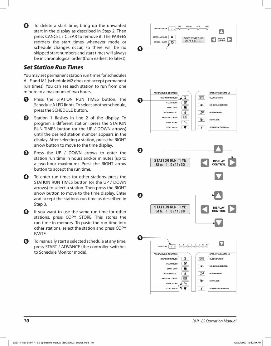
To delete a start time, bring up the unwanted 5.start in the display as described in Step 2� Then press CANCEL / CLEAR to remove it� The PAR+ES reorders the start times whenever mode or schedule changes occur, so there will be no skipped start numbers and start times will always be in chronological order (from earliest to latest)�
Set Station Run TimesYou may set permanent station run times for schedules A - F and M1 (schedule M2 does not accept permanent run times)� You can set each station to run from one minute to a maximum of two hours�
Press the STATION RUN TIMES button� The 1.Schedule A LED lights� To select another schedule, press the SCHEDULE button�
Station 1 flashes in line 2 of the display� To 2.program a different station, press the STATION RUN TIMES button (or the UP / DOWN arrows) until the desired station number appears in the display� After selecting a station, press the RIGHT arrow button to move to the time display�
Press the UP / DOWN arrows to enter the 3.station run time in hours and/or minutes (up to a two-hour maximum)� Press the RIGHT arrow button to accept the run time�
To enter run times for other stations, press the 4.STATION RUN TIMES button (or the UP / DOWN arrows) to select a station� Then press the RIGHT arrow button to move to the time display� Enter and accept the station’s run time as described in Step 3�
If you want to use the same run time for other 5.stations, press COPY STORE� This stores the run time in memory� To paste the run time into other stations, select the station and press COPY PASTE�
To manually start a selected schedule at any time, 6.press START / ADVANCE (the controller switches to Schedule Monitor mode)�
SCHED START TIMEStart 1 @ --:--
STATION RUN TIMEStn: 1 0:11:00
STATION RUN TIMEStn: 1 0:11:00
5
1
5
3
2
635777 Rev B (PAR+ES operations manual (1of2 ENG)) source.indd 10 12/20/2007 8:40:19 AM
PAR+ES Operation Manual 11
AUTO OFF ON
AUTO OFF ON
AUTO OFF ON
Optional Station SwitchesStation switches are an optional feature available on the PAR+ES controller (not available with Decoder Controllers)� Station switches give you the option of turning individual stations ON or OFF, or letting them water automatically, depending on watering needs�
Station switches are numbered consecutively (1 - 8) from the top of the first Output Station with switches Module (OSM-S)� The second OSM-S controls stations 9 - 16, and so on� Each switch number is imprinted on the OSM-S (to the left of the switch)�
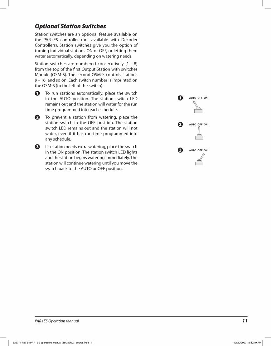
To run stations automatically, place the switch 1.in the AUTO position� The station switch LED remains out and the station will water for the run time programmed into each schedule�
To prevent a station from watering, place the 2.station switch in the OFF position� The station switch LED remains out and the station will not water, even if it has run time programmed into any schedule�
If a station needs extra watering, place the switch 3.in the ON position� The station switch LED lights and the station begins watering immediately� The station will continue watering until you move the switch back to the AUTO or OFF position�
1
2
3
635777 Rev B (PAR+ES operations manual (1of2 ENG)) source.indd 11 12/20/2007 8:40:19 AM

PAR+ES Operation Manual12
PROGRAMMING CONTROLS OPERATING CONTROLS
A B C D E F M1 M2SCHEDULE
STATION RUN TIMES
START TIMES
START DAYS
WATER BUDGET
WEEKDAY / CYCLE
CLOCK STATUS
SCHEDULE MONITOR
MULTI-MANUAL
SET CLOCK
SYSTEM INFORMATION
COPY STORE
COPY PASTE
PROGRAMMING CONTROLS OPERATING CONTROLS
A B C D E F M1 M2SCHEDULE
STATION RUN TIMES
START TIMES
START DAYS
WATER BUDGET
WEEKDAY / CYCLE
CLOCK STATUS
SCHEDULE MONITOR
MULTI-MANUAL
SET CLOCK
SYSTEM INFORMATION
COPY STORE
COPY PASTE
DISPLAYCONTROL
Controller Operation
Set Water BudgetThe water budget feature lets you increase or decrease the run times of all stations on a schedule by a selected percentage� You can set the percentage from 0 to 200%, in 10% increments� Each schedule can have a different water budget percentage�
You can use water budgeting to cut back watering during cool winter months, or to increase watering during warmer weather, without reprogramming station run times� You can also use the 0% setting to temporarily shut off a schedule�
Water budget percentages are calculated on the normal programmed run times for each station� For example, if a station is programmed to run for 10 minutes, and you set the water budget to 80%, the station will run for 8 minutes (80% of 10 minutes)� If you set the water budget to 120%, that same station would run for 12 minutes (120% of 10 minutes)�
Press the WATER BUDGET button� The Schedule A 1.LED lights� Press the SCHEDULE button to select the schedule whose water budget percentage you want to view or change�
The display shows the water budget percentage 2.for the selected schedule (the default is 100%)� Press the UP / DOWN arrow buttons to change the water budget percentage in 10% increments (from 0 to 200%)�
If you want to use the same water budget 3.percentage in another schedule, press COPY STORE� Then press the SCHEDULE button to select the desired schedule and press COPY PASTE to enter the percentage into the other schedule�
SCH WATER BUDGET100%
1
2
3
635777 Rev B (PAR+ES operations manual (1of2 ENG)) source.indd 12 12/20/2007 8:40:19 AM
PAR+ES Operation Manual 13
PROGRAMMING CONTROLS OPERATING CONTROLS
STATION RUN TIMES
START TIMES
START DAYS
WATER BUDGET
WEEKDAY / CYCLE
CLOCK STATUS
SCHEDULE MONITOR
MULTI-MANUAL
SET CLOCK
SYSTEM INFORMATION
COPY STORE
COPY PASTE
CONTROL MODE
START / ADVANCEDISPLAY
CONTROL
OFF MANUAL LOCAL MAXI
CANCEL / CLEAR
DISPLAYCONTROL
CONTROL MODE
START / ADVANCEDISPLAY
CONTROL
OFF MANUAL LOCAL MAXI
CANCEL / CLEAR
DISPLAYCONTROL
CONTROL MODE
START / ADVANCEDISPLAY
CONTROL
OFF MANUAL LOCAL MAXI
CANCEL / CLEAR
Schedule MonitorYou can use the Schedule Monitor function to monitor the status of watering schedules� In Schedule Monitor mode, you can start inactive schedules, change station run times, stop the operation of active stations, and delete or change the run times of manually started stations�
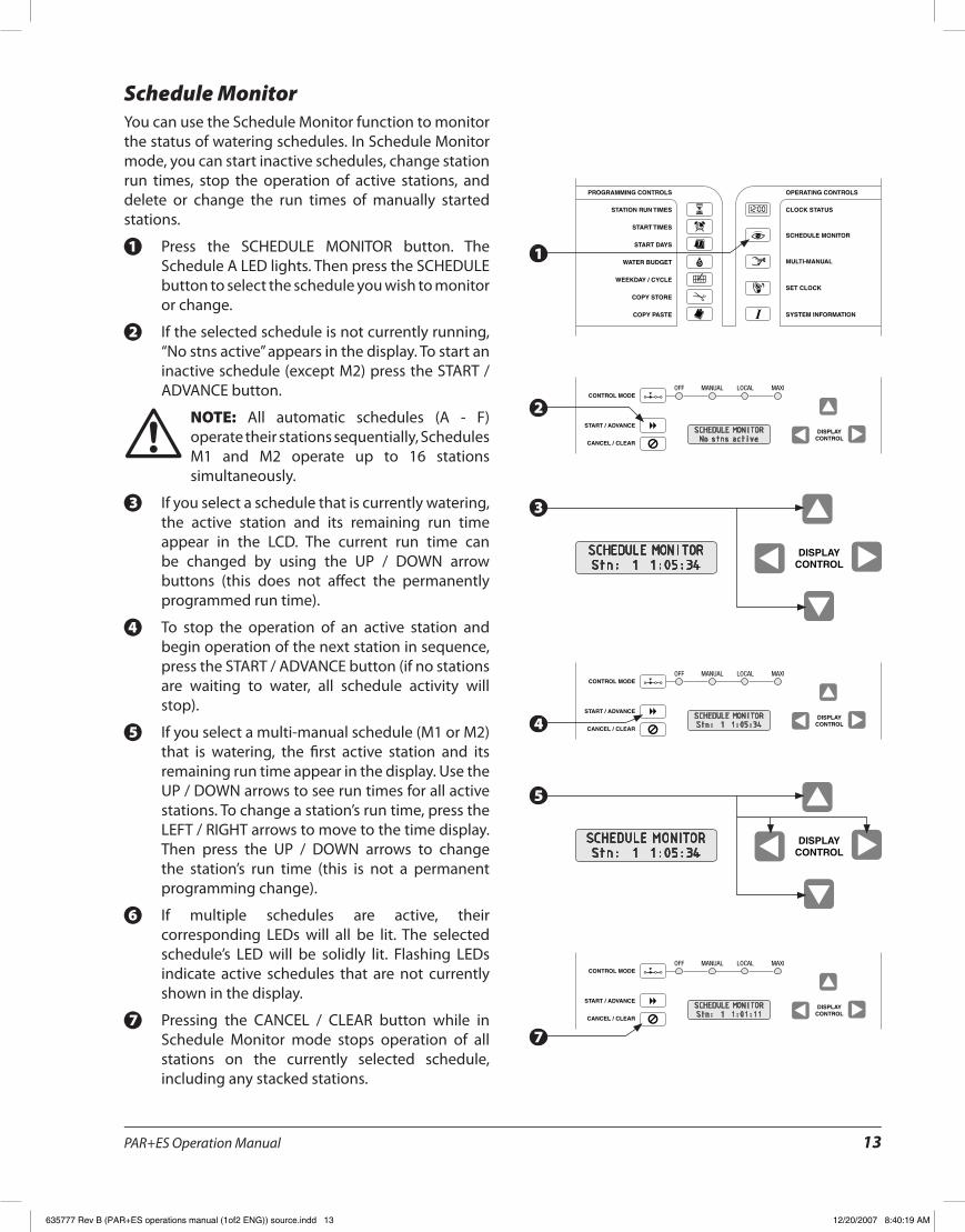
Press the SCHEDULE MONITOR button� The 1.Schedule A LED lights� Then press the SCHEDULE button to select the schedule you wish to monitor or change�
If the selected schedule is not currently running, 2.“No stns active” appears in the display� To start an inactive schedule (except M2) press the START / ADVANCE button�
NOTE: ! All automatic schedules (A - F) operate their stations sequentially, Schedules M1 and M2 operate up to 16 stations simultaneously�
If you select a schedule that is currently watering, 3.the active station and its remaining run time appear in the LCD� The current run time can be changed by using the UP / DOWN arrow buttons (this does not affect the permanently programmed run time)�
To stop the operation of an active station and 4.begin operation of the next station in sequence, press the START / ADVANCE button (if no stations are waiting to water, all schedule activity will stop)�
If you select a multi-manual schedule (M1 or M2) 5.that is watering, the first active station and its remaining run time appear in the display� Use the UP / DOWN arrows to see run times for all active stations� To change a station’s run time, press the LEFT / RIGHT arrows to move to the time display� Then press the UP / DOWN arrows to change the station’s run time (this is not a permanent programming change)�
If multiple schedules are active, their 6.corresponding LEDs will all be lit� The selected schedule’s LED will be solidly lit� Flashing LEDs indicate active schedules that are not currently shown in the display�
Pressing the CANCEL / CLEAR button while in 7.Schedule Monitor mode stops operation of all stations on the currently selected schedule, including any stacked stations�
SCHEDULE MONITORNo stns active
SCHEDULE MONITORStn: 1 1:05:34
SCHEDULE MONITORStn: 1 1:05:34
SCHEDULE MONITORStn: 1 1:05:34
SCHEDULE MONITORStn: 1 1:01:11
1
3
4
5
7
2
635777 Rev B (PAR+ES operations manual (1of2 ENG)) source.indd 13 12/20/2007 8:40:19 AM
PAR+ES Operation Manual14
PROGRAMMING CONTROLS OPERATING CONTROLS
A B C D E F M1 M2SCHEDULE
STATION RUN TIMES
START TIMES
START DAYS
WATER BUDGET
WEEKDAY / CYCLE
CLOCK STATUS
SCHEDULE MONITOR
MULTI-MANUAL
SET CLOCK
SYSTEM INFORMATION
COPY STORE
COPY PASTE
DISPLAYCONTROL
DISPLAYCONTROL
CONTROL MODE
START / ADVANCEDISPLAY
CONTROL
OFF MANUAL LOCAL MAXI
CANCEL / CLEAR
Manual OperationThe Multi-Manual function lets you operate up to 16 valves (@60 Hz), or solenoids simultaneously (including the master valve)� Assuming one valve per station, and no master valve, a maximum of 16 stations can operate at one time� If you assign more than one valve per station, the number of stations that will operate simultaneously drops accordingly�
Run times for schedule M1 are permanently saved, but M2 run times will always default back to three minutes� This provides two options for running manual schedules�
For manual operation, you must select each individual station, enter the desired run time, and then press START / ADVANCE� The station will begin watering immediately�
Once 16 valves are in operation, additional stations entered will be stacked� The newly entered stations will wait until an active station has finished watering before the new station begins�
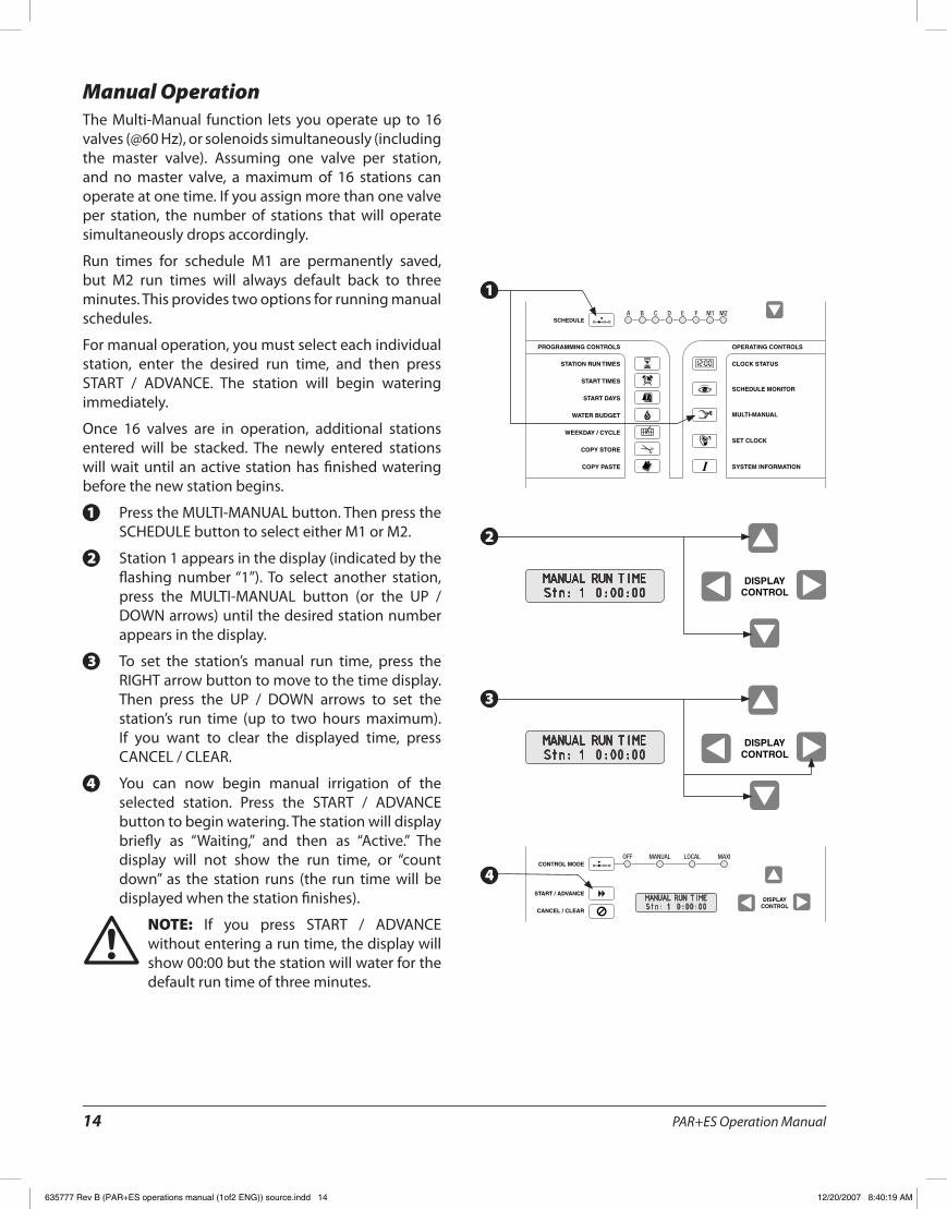
Press the MULTI-MANUAL button� Then press the 1.SCHEDULE button to select either M1 or M2�
Station 1 appears in the display (indicated by the 2.flashing number “1”)� To select another station, press the MULTI-MANUAL button (or the UP / DOWN arrows) until the desired station number appears in the display�
To set the station’s manual run time, press the 3.RIGHT arrow button to move to the time display� Then press the UP / DOWN arrows to set the station’s run time (up to two hours maximum)� If you want to clear the displayed time, press CANCEL / CLEAR�
You can now begin manual irrigation of the 4.selected station� Press the START / ADVANCE button to begin watering� The station will display briefly as “Waiting,” and then as “Active�” The display will not show the run time, or “count down” as the station runs (the run time will be displayed when the station finishes)�
NOTE: ! If you press START / ADVANCE without entering a run time, the display will show 00:00 but the station will water for the default run time of three minutes�
MANUAL RUN TIMEStn: 1 0:00:00
MANUAL RUN TIMEStn: 1 0:00:00
MANUAL RUN TIMEStn: 1 0:00:00
1
2
3
4
635777 Rev B (PAR+ES operations manual (1of2 ENG)) source.indd 14 12/20/2007 8:40:19 AM
PAR+ES Operation Manual 15
CONTROL MODE
START / ADVANCEDISPLAY
CONTROL
OFF MANUAL LOCAL MAXI
CANCEL / CLEAR
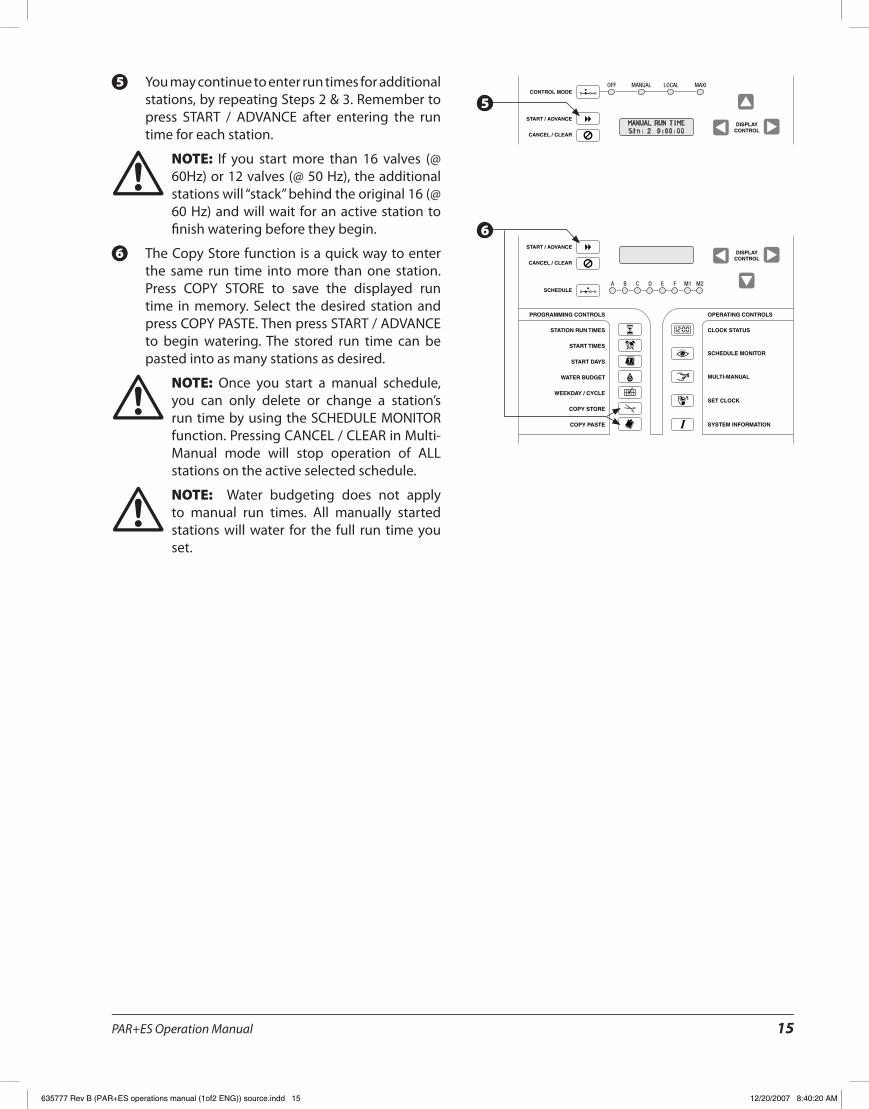
You may continue to enter run times for additional 5.stations, by repeating Steps 2 & 3� Remember to press START / ADVANCE after entering the run time for each station�
NOTE: ! If you start more than 16 valves (@ 60Hz) or 12 valves (@ 50 Hz), the additional stations will “stack” behind the original 16 (@ 60 Hz) and will wait for an active station to finish watering before they begin�
The Copy Store function is a quick way to enter 6.the same run time into more than one station� Press COPY STORE to save the displayed run time in memory� Select the desired station and press COPY PASTE� Then press START / ADVANCE to begin watering� The stored run time can be pasted into as many stations as desired�
NOTE: ! Once you start a manual schedule, you can only delete or change a station’s run time by using the SCHEDULE MONITOR function� Pressing CANCEL / CLEAR in Multi-Manual mode will stop operation of ALL stations on the active selected schedule�
NOTE: ! Water budgeting does not apply to manual run times� All manually started stations will water for the full run time you set�
MANUAL RUN TIMEStn: 2 0:00:00
5
6
635777 Rev B (PAR+ES operations manual (1of2 ENG)) source.indd 15 12/20/2007 8:40:20 AM
PAR+ES Operation Manual16
DISPLAYCONTROL
PROGRAMMING CONTROLS OPERATING CONTROLS
STATION RUN TIMES
START TIMES
START DAYS
WATER BUDGET
WEEKDAY / CYCLE
CLOCK STATUS
SCHEDULE MONITOR
MULTI-MANUAL
SET CLOCK
SYSTEM INFORMATION
COPY STORE
COPY PASTE
Special Controller Functions
System InformationThe System Information function displays information about the controller’s software version and type of interface� It allows you to set certain controller options, such as satellite channel ID numbers, the number of valves installed per station, LCD display language, rain sensor system status, and the station limit (number of stations that can be turned on without tripping the circuit breaker)�
The System Information function also lets you access diagnostic tests described in the “Production Tests” section� (For Decoder Controllers the System Information function also lets you access the “Decoder Menu�”)�
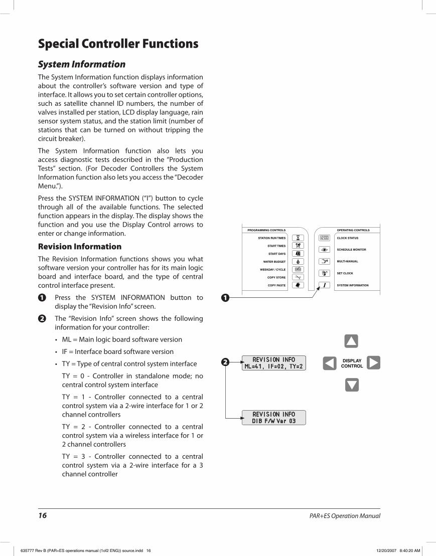
Press the SYSTEM INFORMATION (“I”) button to cycle through all of the available functions� The selected function appears in the display� The display shows the function and you use the Display Control arrows to enter or change information�
Revision InformationThe Revision Information functions shows you what software version your controller has for its main logic board and interface board, and the type of central control interface present�
Press the SYSTEM INFORMATION button to 1.display the “Revision Info” screen�
The “Revision Info” screen shows the following 2.information for your controller:
ML = Main logic board software version•
IF = Interface board software version•
TY = Type of central control system interface•
TY = 0 - Controller in standalone mode; no central control system interface
TY = 1 - Controller connected to a central control system via a 2-wire interface for 1 or 2 channel controllers
TY = 2 - Controller connected to a central control system via a wireless interface for 1 or 2 channel controllers
TY = 3 - Controller connected to a central control system via a 2-wire interface for a 3 channel controller
REVISION INFOML=41, IF=02, TY=2REVISION INFO
ML=41, IF=02, TY=2
REVISION INFODIB F/W Ver 03
1
2
635777 Rev B (PAR+ES operations manual (1of2 ENG)) source.indd 16 12/20/2007 8:40:20 AM
PAR+ES Operation Manual 17
PROGRAMMING CONTROLS OPERATING CONTROLS
STATION RUN TIMES
START TIMES
START DAYS
WATER BUDGET
WEEKDAY / CYCLE
CLOCK STATUS
SCHEDULE MONITOR
MULTI-MANUAL
SET CLOCK
SYSTEM INFORMATION
COPY STORE
COPY PASTE
DISPLAYCONTROL
DISPLAYCONTROL
DISPLAYCONTROL
PROGRAMMING CONTROLS OPERATING CONTROLS
STATION RUN TIMES
START TIMES
START DAYS
WATER BUDGET
WEEKDAY / CYCLE
CLOCK STATUS
SCHEDULE MONITOR
MULTI-MANUAL
SET CLOCK
SYSTEM INFORMATION
COPY STORE
COPY PASTE
TY = 4 - Controller connected to a central control system via a wireless interface for 3 channel controller
If a DIB is present the screen will alternate to •show DIB firmware version�
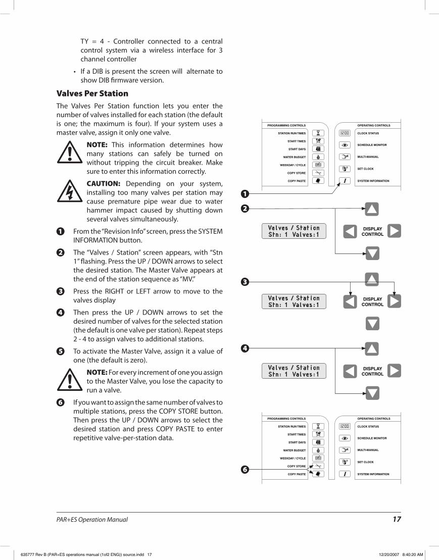
Valves Per StationThe Valves Per Station function lets you enter the number of valves installed for each station (the default is one; the maximum is four)� If your system uses a master valve, assign it only one valve�
NOTE: ! This information determines how many stations can safely be turned on without tripping the circuit breaker� Make sure to enter this information correctly�
CAUTION: F Depending on your system, installing too many valves per station may cause premature pipe wear due to water hammer impact caused by shutting down several valves simultaneously�
From the “Revision Info” screen, press the SYSTEM 1.INFORMATION button�
The “Valves / Station” screen appears, with “Stn 2.1” flashing� Press the UP / DOWN arrows to select the desired station� The Master Valve appears at the end of the station sequence as “MV�”
Press the RIGHT or LEFT arrow to move to the 3.valves display
Then press the UP / DOWN arrows to set the 4.desired number of valves for the selected station (the default is one valve per station)� Repeat steps 2 - 4 to assign valves to additional stations�
To activate the Master Valve, assign it a value of 5.one (the default is zero)�
NOTE: ! For every increment of one you assign to the Master Valve, you lose the capacity to run a valve�
If you want to assign the same number of valves to 6.multiple stations, press the COPY STORE button� Then press the UP / DOWN arrows to select the desired station and press COPY PASTE to enter repetitive valve-per-station data�
Valves / StationStn: 1 Valves:1
Valves / StationStn: 1 Valves:1
Valves / StationStn: 1 Valves:1
1
2
3
4
6
635777 Rev B (PAR+ES operations manual (1of2 ENG)) source.indd 17 12/20/2007 8:40:20 AM

PAR+ES Operation Manual18
DISPLAYCONTROL
DISPLAYCONTROL
PROGRAMMING CONTROLS OPERATING CONTROLS
STATION RUN TIMES
START TIMES
START DAYS
WATER BUDGET
WEEKDAY / CYCLE
CLOCK STATUS
SCHEDULE MONITOR
MULTI-MANUAL
SET CLOCK
SYSTEM INFORMATION
COPY STORE
COPY PASTE
Satellite IdentificationThis function lets you program the PAR+ES to respond to channel ID numbers so it can be used as a satellite by a MAXI central control system� To do this, the PAR+ES must be programmed to respond to channel ID numbers (each 24 stations on the controller is called a “channel�” There are three channels, A, B, and C� Channel A controls stations 1 - 24� Channel B controls stations 25 - 48, and Channel C controls stations 49 - 72�
All channels are programmed the same way, except that each channel must be assigned a unique [different] ID number� Available ID numbers scroll from 1 through 28�
NOTE: ! Channel B is not visible in the display until you have assigned an ID number to channel A, and only if more than 24 stations are available at controller�
NOTE: ! For the PAR+ES to be used as a satellite by a central control unit, the Control Mode must be set to MAXI� In any other mode, the PAR+ES will not respond to commands from a Rain Bird central control�
For Use with a MAXIFrom the “Valves / Station” screen, press the 1.SYSTEM INFORMATION button� The “Satellite ID” screen appears, displaying the channel number(s) on line 2� The default channel setting is 0 (inactive)�
To set channel A, press the UP / DOWN arrows 2.until the desired ID number (1 - 28) appears in the display� The controller will now respond to this ID for channel A� Also, channel B will become visible in the display, separated from channel A by a slash (/)�
To set channel B, press the RIGHT arrow button� 3.Then press the UP / DOWN arrows until the desired channel B ID number (1 - 28) appears in the display (you must select a different ID number for channel B than you chose for channel A)� The controller will now respond to this ID number for channel B�
For each channel, the PAR+ES will respond to 4.the MAXI unit’s corresponding Group Control Modules�
NOTE: ! The MAXI software handles channels A, B, and C as if they are three separate satellites, even though there is just one PAR+ES controller physically present�
Satellite IDChannel: 1
Satellite IDChannel: 1
1
2
3
635777 Rev B (PAR+ES operations manual (1of2 ENG)) source.indd 18 12/20/2007 8:40:20 AM
PAR+ES Operation Manual 19
DISPLAYCONTROL
PROGRAMMING CONTROLS OPERATING CONTROLS
STATION RUN TIMES
START TIMES
START DAYS
WATER BUDGET
WEEKDAY / CYCLE
CLOCK STATUS
SCHEDULE MONITOR
MULTI-MANUAL
SET CLOCK
SYSTEM INFORMATION
COPY STORE
COPY PASTE
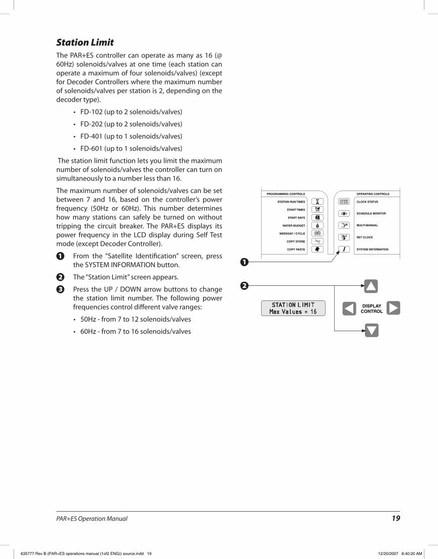
Station LimitThe PAR+ES controller can operate as many as 16 (@ 60Hz) solenoids/valves at one time (each station can operate a maximum of four solenoids/valves) (except for Decoder Controllers where the maximum number of solenoids/valves per station is 2, depending on the decoder type)�
FD-102 (up to 2 solenoids/valves)•
FD-202 (up to 2 solenoids/valves)•
FD-401 (up to 1 solenoids/valves)•
FD-601 (up to 1 solenoids/valves)•
The station limit function lets you limit the maximum number of solenoids/valves the controller can turn on simultaneously to a number less than 16�
The maximum number of solenoids/valves can be set between 7 and 16, based on the controller’s power frequency (50Hz or 60Hz)� This number determines how many stations can safely be turned on without tripping the circuit breaker� The PAR+ES displays its power frequency in the LCD display during Self Test mode (except Decoder Controller)�
From the “Satellite Identification” screen, press 1.the SYSTEM INFORMATION button�
The “Station Limit” screen appears�2.
Press the UP / DOWN arrow buttons to change 3.the station limit number� The following power frequencies control different valve ranges:
50Hz - from 7 to 12 solenoids/valves•
60Hz - from 7 to 16 solenoids/valves•
STATION LIMITMax Values = 16
1
2
635777 Rev B (PAR+ES operations manual (1of2 ENG)) source.indd 19 12/20/2007 8:40:20 AM
PAR+ES Operation Manual20
Decoder Controller Setup
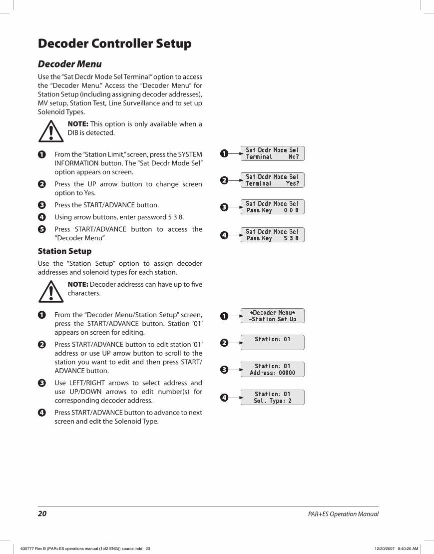
Decoder MenuUse the “Sat Decdr Mode Sel Terminal” option to access the “Decoder Menu�” Access the “Decoder Menu” for Station Setup (including assigning decoder addresses), MV setup, Station Test, Line Surveillance and to set up Solenoid Types�
NOTE: ! This option is only available when a DIB is detected�
From the “Station Limit,” screen, press the SYSTEM 1.INFORMATION button� The “Sat Decdr Mode Sel” option appears on screen�
Press the UP arrow button to change screen 2.option to Yes�
Press the START/ADVANCE button�3.
Using arrow buttons, enter password 5 3 8�4.
Press START/ADVANCE button to access the 5.“Decoder Menu”
Station SetupUse the “Station Setup” option to assign decoder addresses and solenoid types for each station�
NOTE: ! Decoder addresss can have up to five characters�
From the “Decoder Menu/Station Setup” screen, 1.press the START/ADVANCE button� Station ‘01’ appears on screen for editing�
Press START/ADVANCE button to edit station ‘01’ 2.address or use UP arrow button to scroll to the station you want to edit and then press START/ADVANCE button�
Use LEFT/RIGHT arrows to select address and 3.use UP/DOWN arrows to edit number(s) for corresponding decoder address�
Press START/ADVANCE button to advance to next 4.screen and edit the Solenoid Type�
Sat Dcdr Mode SelTerminal No?
Sat Dcdr Mode SelTerminal Yes?
Sat Dcdr Mode SelPass Key 0 0 0
Sat Dcdr Mode SelPass Key 5 3 8
*Decoder Menu*-Station Set Up
Station: 01
Station: 01Address: 00000
Station: 01Sol. Type: 2
1
2
3
4
1
2
3
4
635777 Rev B (PAR+ES operations manual (1of2 ENG)) source.indd 20 12/20/2007 8:40:20 AM
PAR+ES Operation Manual 21
NOTE: ! The “Solenoid Type” refers to the switch code setting� Each “Switch Code” setting has a specific “Activation Time” and “Holding Voltage�” The default “Solenoid Types” are listed in the “Solenoid Type” section� There are 6 to choose from (1-6), 2 being the default� They are customizable for
each golf course�
Repeat steps 2-4 for each station�5.
When done, press CONTROL MODE button to exit 6.menu and return to “Decoder Menu”
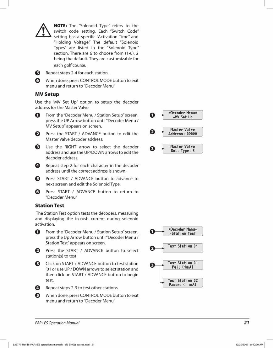
MV SetupUse the “MV Set Up” option to setup the decoder address for the Master Valve�
From the “Decoder Menu / Station Setup” screen, 1.press the UP Arrow button until “Decoder Menu / MV Setup” appears on screen�
Press the START / ADVANCE button to edit the 2.Master Valve decoder address�
Use the RIGHT arrow to select the decoder 3.address and use the UP/DOWN arrows to edit the decoder address�
Repeat step 2 for each character in the decoder 4.address until the correct address is shown�
Press START / ADVANCE button to advance to 5.next screen and edit the Solenoid Type�
Press START / ADVANCE button to return to 6.“Decoder Menu”
Station Test The Station Test option tests the decoders, measuring and displaying the in-rush current during solenoid activation�
From the “Decoder Menu / Station Setup” screen, 1.press the Up Arrow button until “Decoder Menu / Station Test” appears on screen�
Press the START / ADVANCE button to select 2.station(s) to test�
Click on START / ADVANCE button to test station 3.‘01 or use UP / DOWN arrows to select station and then click on START / ADVANCE button to begin test�
Repeat steps 2-3 to test other stations�4.
When done, press CONTROL MODE button to exit 5.menu and return to “Decoder Menu”
*Decoder Menu*-MV Set Up
Master ValveAddress: 00000
Master ValveSol. Type: 3
*Decoder Menu*-Station Test
Test Station 01
Test Station 01Fail (1mA)
Test Station 02Passed ( mA)
1
2
3
1
2
3
635777 Rev B (PAR+ES operations manual (1of2 ENG)) source.indd 21 12/20/2007 8:40:20 AM
PAR+ES Operation Manual22
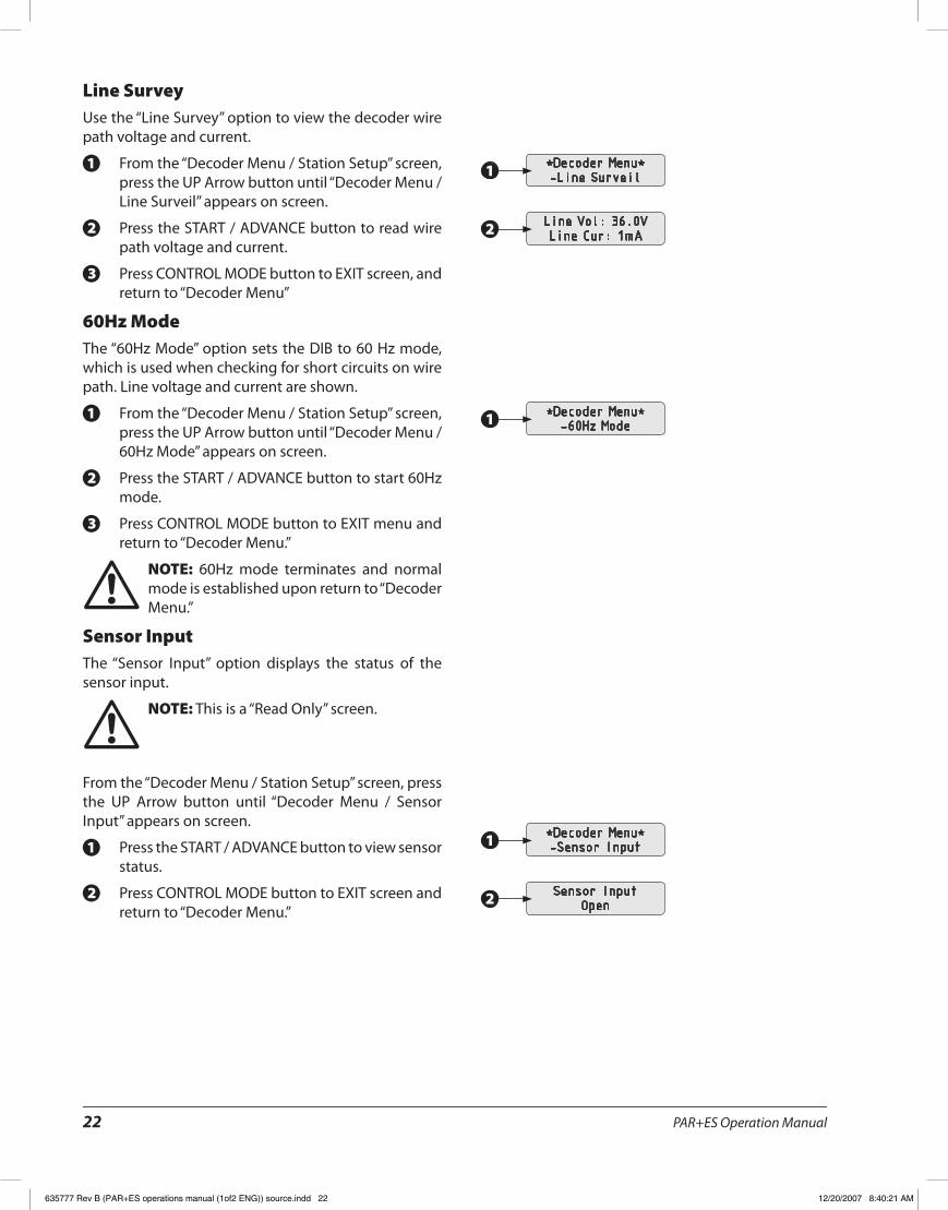
Line SurveyUse the “Line Survey” option to view the decoder wire path voltage and current�
From the “Decoder Menu / Station Setup” screen, 1.press the UP Arrow button until “Decoder Menu / Line Surveil” appears on screen�
Press the START / ADVANCE button to read wire 2.path voltage and current�
Press CONTROL MODE button to EXIT screen, and 3.return to “Decoder Menu”
60Hz ModeThe “60Hz Mode” option sets the DIB to 60 Hz mode, which is used when checking for short circuits on wire path� Line voltage and current are shown�
From the “Decoder Menu / Station Setup” screen, 1.press the UP Arrow button until “Decoder Menu / 60Hz Mode” appears on screen�
Press the START / ADVANCE button to start 60Hz 2.mode�
Press CONTROL MODE button to EXIT menu and 3.return to “Decoder Menu�”
NOTE: ! 60Hz mode terminates and normal mode is established upon return to “Decoder Menu�”
Sensor InputThe “Sensor Input” option displays the status of the sensor input�
NOTE: ! This is a “Read Only” screen�
From the “Decoder Menu / Station Setup” screen, press the UP Arrow button until “Decoder Menu / Sensor Input” appears on screen�
Press the START / ADVANCE button to view sensor 1.status�
Press CONTROL MODE button to EXIT screen and 2.return to “Decoder Menu�”
*Decoder Menu*-Line Surveil
Line Vol: 36.0VLine Cur: 1mA
*Decoder Menu*-Sensor Input
Sensor InputOpen
*Decoder Menu*-60Hz Mode
1
2
1
2
1
635777 Rev B (PAR+ES operations manual (1of2 ENG)) source.indd 22 12/20/2007 8:40:21 AM
PAR+ES Operation Manual 23
Solenoid TypeUse the “Solenoid Type” option to set up as many as 6 different switch codes for use with various solenoid types� Each switch code setting can have a different “Activation Time” and/or “Holding Voltage�” The default switch codes programmed at the controller are:
59F350• 30ms 2�3Vh/Volt
59F350• 30ms 2�3Vh/Volt
59F350• 30ms 2�3Vh/Volt
59F370• 30ms 3�5 Vh/Volt
59F380• 30ms 4�0Vh/Volt
59F3A0• 30ms 5�2 Vh/Volt
NOTE: ! Refer to the “Decoder” manual (GT27141B) for other switch code settings�
From the “Decoder Menu / Station Setup” screen, 1.press the UP Arrow button until “Decoder Menu / Solenoid Type” appears on screen�
Press the START / ADVANCE button�2.
To edit Solenoid Type 1, press START / ADVANCE 3.button otherwise use UP/DOWN Arrows to select station, then press START /ADVANCE button�
Use the UP /DOWN arrows to edit Solenoid Type�4.
Repeat step 2 - 3 for each solenoid type, up to 5.solenoid type 6
Returns to “Decoder Menu / Station Setup” screen 6.following solenoid type 6 setup�
Exit MenuUse the “Exit Menu” option to exit the Decoder 1.Menu and return to standard controller operation�
From the “Decoder Menu / Station Setup” screen, 2.press the UP Arrow button until “Decoder Menu / Exit Menu” appears on screen�
Press the START / ADVANCE button to exit 3.Decoder Menu and return to Clock Status�
NOTE: ! There is a 10-second delay before the clock status appears on front panel display�
635777 Rev B (PAR+ES operations manual (1of2 ENG)) source.indd 23 12/20/2007 8:40:21 AM
PAR+ES Operation Manual24
DISPLAYCONTROL
PROGRAMMING CONTROLS OPERATING CONTROLS
STATION RUN TIMES
START TIMES
START DAYS
WATER BUDGET
WEEKDAY / CYCLE
CLOCK STATUS
SCHEDULE MONITOR
MULTI-MANUAL
SET CLOCK
SYSTEM INFORMATION
COPY STORE
COPY PASTE
PROGRAMMING CONTROLS OPERATING CONTROLS
STATION RUN TIMES
START TIMES
START DAYS
WATER BUDGET
WEEKDAY / CYCLE
CLOCK STATUS
SCHEDULE MONITOR
MULTI-MANUAL
SET CLOCK
SYSTEM INFORMATION
COPY STORE
COPY PASTE
CONTROL MODE
START / ADVANCEDISPLAY
CONTROL
OFF MANUAL LOCAL MAXI
CANCEL / CLEAR
DISPLAYCONTROL
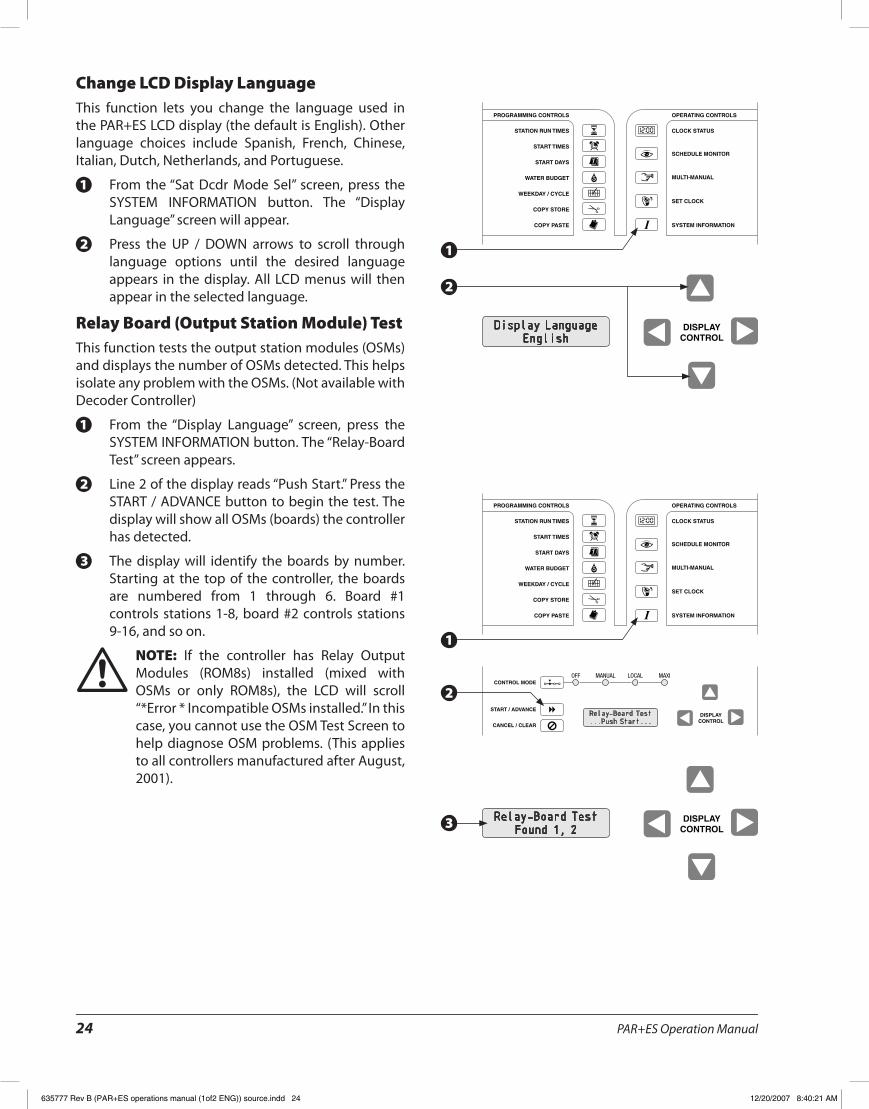
Change LCD Display LanguageThis function lets you change the language used in the PAR+ES LCD display (the default is English)� Other language choices include Spanish, French, Chinese, Italian, Dutch, Netherlands, and Portuguese�
From the “Sat Dcdr Mode Sel” screen, press the 1.SYSTEM INFORMATION button� The “Display Language” screen will appear�
Press the UP / DOWN arrows to scroll through 2.language options until the desired language appears in the display� All LCD menus will then appear in the selected language�
Relay Board (Output Station Module) TestThis function tests the output station modules (OSMs) and displays the number of OSMs detected� This helps isolate any problem with the OSMs� (Not available with Decoder Controller)
From the “Display Language” screen, press the 1.SYSTEM INFORMATION button� The “Relay-Board Test” screen appears�
Line 2 of the display reads “Push Start�” Press the 2.START / ADVANCE button to begin the test� The display will show all OSMs (boards) the controller has detected�
The display will identify the boards by number� 3.Starting at the top of the controller, the boards are numbered from 1 through 6� Board #1 controls stations 1-8, board #2 controls stations 9-16, and so on�
NOTE: ! If the controller has Relay Output Modules (ROM8s) installed (mixed with OSMs or only ROM8s), the LCD will scroll “*Error * Incompatible OSMs installed�” In this case, you cannot use the OSM Test Screen to help diagnose OSM problems� (This applies to all controllers manufactured after August, 2001)�
Display LanguageEnglish
Relay-Board Test...Push Start...
Relay-Board TestFound 1, 2
1
2
1
3
2
635777 Rev B (PAR+ES operations manual (1of2 ENG)) source.indd 24 12/20/2007 8:40:21 AM
PAR+ES Operation Manual 25
DISPLAYCONTROL
PROGRAMMING CONTROLS OPERATING CONTROLS
STATION RUN TIMES
START TIMES
START DAYS
WATER BUDGET
WEEKDAY / CYCLE
CLOCK STATUS
SCHEDULE MONITOR
MULTI-MANUAL
SET CLOCK
SYSTEM INFORMATION
COPY STORE
COPY PASTE
PROGRAMMING CONTROLS OPERATING CONTROLS
STATION RUN TIMES
START TIMES
START DAYS
WATER BUDGET
WEEKDAY / CYCLE
CLOCK STATUS
SCHEDULE MONITOR
MULTI-MANUAL
SET CLOCK
SYSTEM INFORMATION
COPY STORE
COPY PASTE
CONTROL MODE
START / ADVANCEDISPLAY
CONTROL
OFF MANUAL LOCAL MAXI
CANCEL / CLEAR
DISPLAYCONTROL
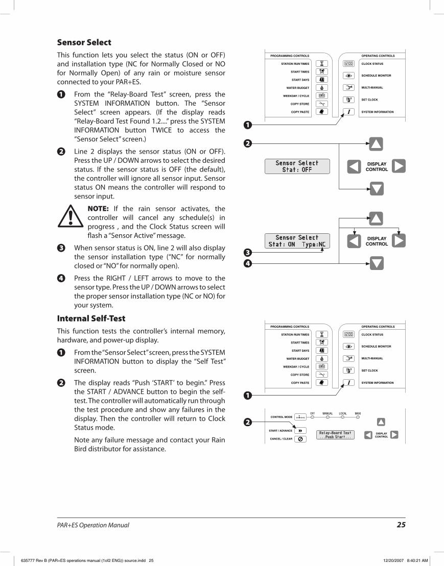
Sensor SelectThis function lets you select the status (ON or OFF) and installation type (NC for Normally Closed or NO for Normally Open) of any rain or moisture sensor connected to your PAR+ES�
From the “Relay-Board Test” screen, press the 1.SYSTEM INFORMATION button� The “Sensor Select” screen appears� (If the display reads “Relay-Board Test Found 1�2����” press the SYSTEM INFORMATION button TWICE to access the “Sensor Select” screen�)
Line 2 displays the sensor status (ON or OFF)� 2.Press the UP / DOWN arrows to select the desired status� If the sensor status is OFF (the default), the controller will ignore all sensor input� Sensor status ON means the controller will respond to sensor input�
NOTE: ! If the rain sensor activates, the controller will cancel any schedule(s) in progress , and the Clock Status screen will flash a “Sensor Active” message�
When sensor status is ON, line 2 will also display 3.the sensor installation type (“NC” for normally closed or “NO” for normally open)�
Press the RIGHT / LEFT arrows to move to the 4.sensor type� Press the UP / DOWN arrows to select the proper sensor installation type (NC or NO) for your system�
Internal Self-TestThis function tests the controller’s internal memory, hardware, and power-up display�
From the “Sensor Select” screen, press the SYSTEM 1.INFORMATION button to display the “Self Test” screen�
The display reads “Push ‘START’ to begin�” Press 2.the START / ADVANCE button to begin the self-test� The controller will automatically run through the test procedure and show any failures in the display� Then the controller will return to Clock Status mode�
Note any failure message and contact your Rain Bird distributor for assistance�
Sensor SelectStat: OFF
Relay-Board Test...Push Start...
Sensor SelectStat: ON Type:NC
1
2
1
4
3
2
635777 Rev B (PAR+ES operations manual (1of2 ENG)) source.indd 25 12/20/2007 8:40:21 AM
PAR+ES Operation Manual26
DISPLAYCONTROL
PROGRAMMING CONTROLS OPERATING CONTROLS
STATION RUN TIMES
START TIMES
START DAYS
WATER BUDGET
WEEKDAY / CYCLE
CLOCK STATUS
SCHEDULE MONITOR
MULTI-MANUAL
SET CLOCK
SYSTEM INFORMATION
COPY STORE
COPY PASTE
CONTROL MODE
START / ADVANCEDISPLAY
CONTROL
OFF MANUAL LOCAL MAXI
CANCEL / CLEAR
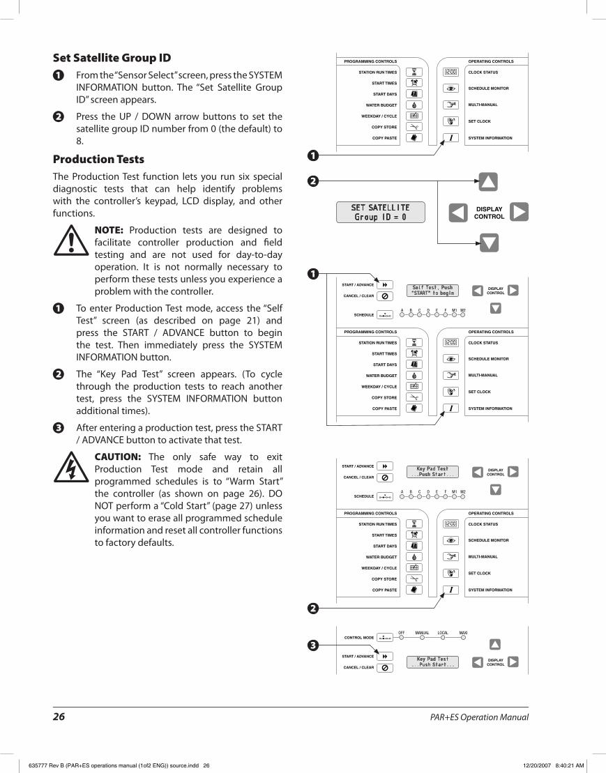
Set Satellite Group IDFrom the “Sensor Select” screen, press the SYSTEM 1.INFORMATION button� The “Set Satellite Group ID” screen appears�
Press the UP / DOWN arrow buttons to set the 2.satellite group ID number from 0 (the default) to 8�
Production TestsThe Production Test function lets you run six special diagnostic tests that can help identify problems with the controller’s keypad, LCD display, and other functions�
NOTE: ! Production tests are designed to facilitate controller production and field testing and are not used for day-to-day operation� It is not normally necessary to perform these tests unless you experience a problem with the controller�
To enter Production Test mode, access the “Self 1.Test” screen (as described on page 21) and press the START / ADVANCE button to begin the test� Then immediately press the SYSTEM INFORMATION button�
The “Key Pad Test” screen appears� (To cycle 2.through the production tests to reach another test, press the SYSTEM INFORMATION button additional times)�
After entering a production test, press the START 3./ ADVANCE button to activate that test�
CAUTION: F The only safe way to exit Production Test mode and retain all programmed schedules is to “Warm Start” the controller (as shown on page 26)� DO NOT perform a “Cold Start” (page 27) unless you want to erase all programmed schedule information and reset all controller functions to factory defaults�
SET SATELLITEGroup ID = 0
Key Pad Test...Push Start...
Key Pad Test...Push Start...
Self Test, Push“START” to begin
1
2
2
1
3
635777 Rev B (PAR+ES operations manual (1of2 ENG)) source.indd 26 12/20/2007 8:40:21 AM
PAR+ES Operation Manual 27
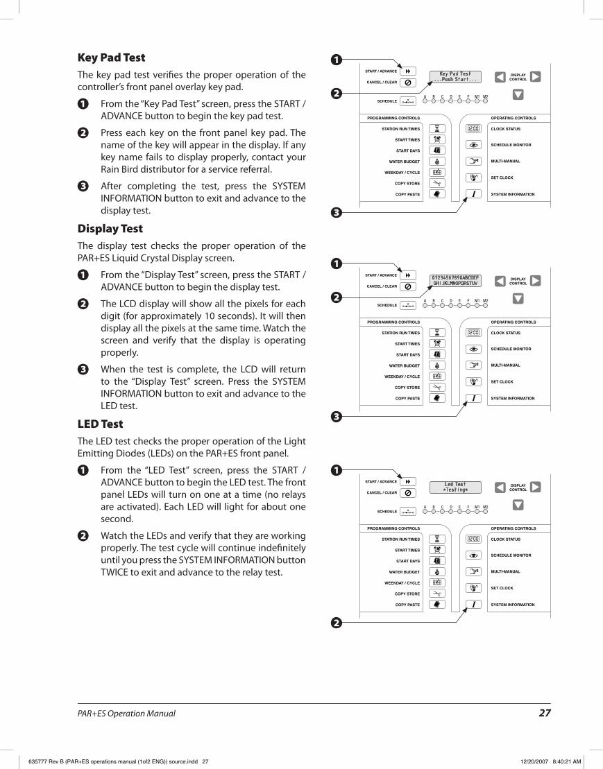
Key Pad TestThe key pad test verifies the proper operation of the controller’s front panel overlay key pad�
From the “Key Pad Test” screen, press the START / 1.ADVANCE button to begin the key pad test�
Press each key on the front panel key pad� The 2.name of the key will appear in the display� If any key name fails to display properly, contact your Rain Bird distributor for a service referral�
After completing the test, press the SYSTEM 3.INFORMATION button to exit and advance to the display test�
Display TestThe display test checks the proper operation of the PAR+ES Liquid Crystal Display screen�
From the “Display Test” screen, press the START / 1.ADVANCE button to begin the display test�
The LCD display will show all the pixels for each 2.digit (for approximately 10 seconds)� It will then display all the pixels at the same time� Watch the screen and verify that the display is operating properly�
When the test is complete, the LCD will return 3.to the “Display Test” screen� Press the SYSTEM INFORMATION button to exit and advance to the LED test�
LED TestThe LED test checks the proper operation of the Light Emitting Diodes (LEDs) on the PAR+ES front panel�
From the “LED Test” screen, press the START / 1.ADVANCE button to begin the LED test� The front panel LEDs will turn on one at a time (no relays are activated)� Each LED will light for about one second�
Watch the LEDs and verify that they are working 2.properly� The test cycle will continue indefinitely until you press the SYSTEM INFORMATION button TWICE to exit and advance to the relay test�
Key Pad Test...Push Start...
01234567890ABCDEFGHIJKLMNOPQRSTUV
Led Test *Testing*
3
2
3
2
2
1
1
1
635777 Rev B (PAR+ES operations manual (1of2 ENG)) source.indd 27 12/20/2007 8:40:21 AM
PAR+ES Operation Manual28
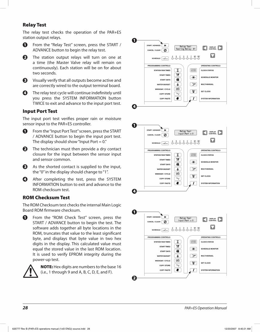
Relay TestThe relay test checks the operation of the PAR+ES station output relays�
From the “Relay Test” screen, press the START / 1.ADVANCE button to begin the relay test�
The station output relays will turn on one at 2.a time (the Master Valve relay will remain on continuously)� Each station will be on for about two seconds�
Visually verify that all outputs become active and 3.are correctly wired to the output terminal board�
The relay test cycle will continue indefinitely until 4.you press the SYSTEM INFORMATION button TWICE to exit and advance to the input port test�
Input Port TestThe input port test verifies proper rain or moisture sensor input to the PAR+ES controller�
From the “Input Port Test” screen, press the START 1./ ADVANCE button to begin the input port test� The display should show “Input Port = 0�”
The technician must then provide a dry contact 2.closure for the input between the sensor input and sensor common�
As the shorted contact is supplied to the input, 3.the “0” in the display should change to “1”�
After completing the test, press the SYSTEM 4.INFORMATION button to exit and advance to the ROM checksum test�
ROM Checksum TestThe ROM Checksum test checks the internal Main Logic Board ROM firmware checksum�
From the “ROM Check Test” screen, press the 1.START / ADVANCE button to begin the test� The software adds together all byte locations in the ROM, truncates that value to the least significant byte, and displays that byte value in two hex digits in the display� This calculated value must equal the stored value in the last ROM location� It is used to verify EPROM integrity during the power-up test�
NOTE: ! Hex digits are numbers to the base 16 (i�e�, 1 through 9 and A, B, C, D, E, and F)�
Relay TestTesting Relay: 01
Relay TestInput Port = 0
Relay TestInput Port = 0
4
4
2
1
1
1
635777 Rev B (PAR+ES operations manual (1of2 ENG)) source.indd 28 12/20/2007 8:40:21 AM
PAR+ES Operation Manual 29
CONTROL MODE
START / ADVANCEDISPLAY
CONTROL
OFF MANUAL LOCAL MAXI
CANCEL / CLEAR
CONTROL MODE
START / ADVANCEDISPLAY
CONTROL
OFF MANUAL LOCAL MAXI
CANCEL / CLEAR
After completing the test, press the SYSTEM 2.INFORMATION button TWICE to exit the ROM Checksum test and advance to the “Warm Start” screen which allows you to exit Production Test mode�
Warm StartNOTE: ! The Warm Start is the only safe exit from Production Test mode (other than turning the power off) that will not erase all programming from the controller’s memory and reset all program variables to factory defaults�
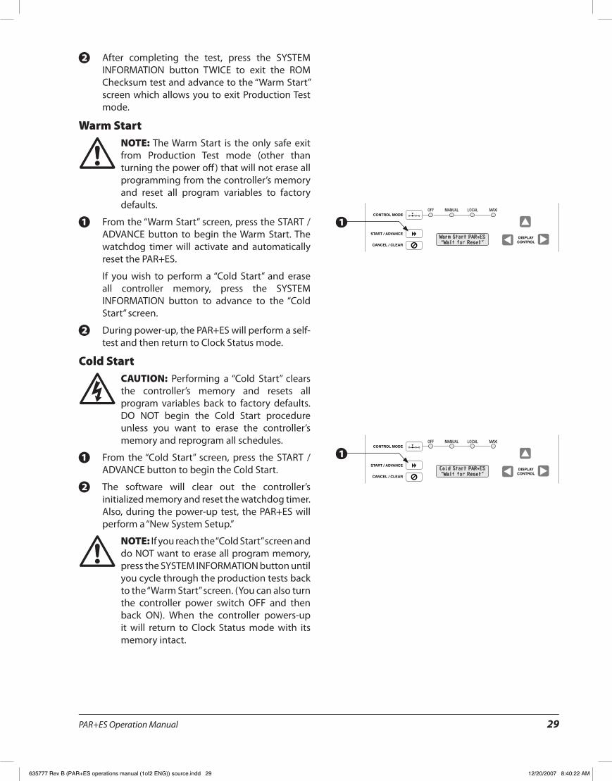
From the “Warm Start” screen, press the START / 1.ADVANCE button to begin the Warm Start� The watchdog timer will activate and automatically reset the PAR+ES�
If you wish to perform a “Cold Start” and erase all controller memory, press the SYSTEM INFORMATION button to advance to the “Cold Start” screen�
During power-up, the PAR+ES will perform a self-2.test and then return to Clock Status mode�
Cold StartCAUTION: F Performing a “Cold Start” clears the controller’s memory and resets all program variables back to factory defaults� DO NOT begin the Cold Start procedure unless you want to erase the controller’s memory and reprogram all schedules�
From the “Cold Start” screen, press the START / 1.ADVANCE button to begin the Cold Start�
The software will clear out the controller’s 2.initialized memory and reset the watchdog timer� Also, during the power-up test, the PAR+ES will perform a “New System Setup�”
NOTE: ! If you reach the “Cold Start” screen and do NOT want to erase all program memory, press the SYSTEM INFORMATION button until you cycle through the production tests back to the “Warm Start” screen� (You can also turn the controller power switch OFF and then back ON)� When the controller powers-up it will return to Clock Status mode with its memory intact�
Warm Start PAR+ES“Wait for Reset”
Cold Start PAR+ES“Wait for Reset”
1
1
635777 Rev B (PAR+ES operations manual (1of2 ENG)) source.indd 29 12/20/2007 8:40:22 AM
PAR+ES Operation Manual30
Circuit Breaker Tripped ModeThe PAR+ES goes into circuit breaker tripped mode when excessive current on the station outputs trips the circuit breaker� When the breaker trips, the LCD displays a “Breaker Tripped” message, and you must reset the circuit breaker�
NOTE: ! All controller functions and buttons are inactive until the circuit breaker is reset�
To reset the circuit breaker, press the circuit 1.breaker button� The circuit breaker is located on the upper right side of the Power Interconnect board cover (at the top of the mounting plate assembly inside the controller pedestal�
After resetting the breaker, the LCD display 2.should clear� If the breaker continues to trip, it means there is a problem with the station output wiring or with the number of solenoids (valves) per station� The problem must be identified and corrected to prevent the breaker from tripping repeatedly�
Check the total number of solenoids (valves on 3.each station), and make sure the correct number has been entered in the System Information / Valves per Station function�
CAUTION: F DO NOT hold the circuit breaker in if it continues to trip� This will damage the breaker� Instead, find and repair the cause of the trip�
Adjust LCD Display BrightnessIf the LCD display is too dark to read, you can brighten it by turning the potentiometer on the back panel of the main logic board�
Remove the four long screws from the face of the 1.control panel and lift out the control module�
Remove the four short screws on the back of the 2.control module to expose the main logic board�
The potentiometer is a small, white slotted 3.device located halfway down the right side of the logic board� Use a screwdriver to turn the potentiometer and adjust the display contrast� Then reinstall the screws and replace the control module�
635777 Rev B (PAR+ES operations manual (1of2 ENG)) source.indd 30 12/20/2007 8:40:22 AM

PAR+ES Operation Manual 31
NOTES
635777 Rev B (PAR+ES operations manual (1of2 ENG)) source.indd 31 12/20/2007 8:40:22 AM

PAR+ES Operation Manual32
NOTES
635777 Rev B (PAR+ES operations manual (1of2 ENG)) source.indd 32 12/20/2007 8:40:22 AM

Controls Manufacturing Division
Declaration of Conformity
Application of Council Directives: 89/336/EEC · 72/23/EEC
Standards To Which Conformity Is Declared:
EN55014 AS/NZS1044EN61000-3-2EN61000-3-3EN50082-1:1992EN61000-4-2EN61000-4-3EN61000-4-4EN60335-1:1995 Safety of household and similar electrical appliances
Manufacturer: Rain Bird CoporationControls Manufacturing Division9491 Ridgehaven Court, Suite CSan Diego, CA 92123(262) 963-9311
Importers: Rain Bird Europe, S�A�R�L� - FranceBP7200013792 aix-en-Provence Cedex 3(33) 442 24 44 61
Rain Bird Australia Pty LtdACN 004 644 446P�0� Box 11 Harrisville Qld� 4307
Equipment Description: Irrigation Controller
Equipment Class: Class II, Generic-Res, Comm, L�I�
Model Number: PAR+ES
I the undersigned, hereby declare that the equipment specified above, conforms to the above Directive(s) and Standard(s)�
Place: Tijuana, B�C�, MexicoSignature:
Full Name:John Rafael ZwickPosition:General Manager
635777 Rev B (PAR+ES operations manual (1of2 ENG)) source.indd 33 12/20/2007 8:40:22 AM

Warning: This equipment has been tested and found to comply with the limits for a Class A digital device, pursuant to Part 15 of the FCC Rules� These limits are designed to provide reasonable protection against harmful interference when the equipment is operated in a commercial environment� This equipment generates, uses and can radiate radio frequency energy and if not installed and used in accordance with the instructions, may cause interference to
radio communications� Operation of this equipment in a residential area is likely to cause harmful interference in which case the user will be required to correct the interference at their own expense�
Changes or modifications not expressly approved by Rain Bird Corporation could void the user’s authority to operate the equipment�
Rain Bird Irrigation CorporationGolf Division
6991 Southpoint RoadTuscon, AZ 85706
www.rainbird.com
© 2007 Rain Bird Corporation
® Registered trademark of Rain Bird Corporation P/N: 635777-01
635777 Rev B (PAR+ES operations manual (1of2 ENG)) source.indd 34 12/20/2007 8:40:22 AM