Embed Size (px)
Citation preview
51
Operation Manual Professional Remote Weather Station
Table of Contents Page 1. Introduction………… .................................................................. 52 2. Intended use .............................................................................. 52
Weather Station ......................................................................... 52 System requirements for PC use ................................................ 53 Installation for the USB adapter driver ........................................ 53 Features of the base station ....................................................... 54 Features of the thermo-hygro sensor.......................................... 55 Features of the wind sensor ....................................................... 55 Features of the rain sensor......................................................... 55
3. Safety Notes .............................................................................. 55 4. Packaged contents ..................................................................... 57 5. Setting up ................................................................................... 58 6. Operation using cable connection or wireless 433MHz............... 61 7. LCD overview ............................................................................. 63 8. Function test .............................................................................. 64 9. Mounting .................................................................................... 64 10. Resetting & factory settings ........................................................ 68 11. Function description ................................................................... 70 12. Operation keys ........................................................................... 73 13. Basic programming modes ......................................................... 75 14. MIN/MAX programming modes .................................................. 76 15. Alarm programming modes ........................................................ 78 16. Auto-memory for stored values .................................................. 87 17. Accessories: extensions cables .................................................. 87 18. Changing batteries ..................................................................... 88 19. Interference and problems with operation ................................... 89 20. Transmission range .................................................................... 90 21. Cleaning and maintenance ......................................................... 91 22. Specifications ............................................................................. 91 23. Liability disclaimer ...................................................................... 93
This Operation Manual is part of this product and should be kept in a safe place for future reference. It contains important notes on setup and opera-tion.
52
Please visit our web site www.heavyweather.info for downloads of complete instruction manuals and the most current version of the 'Heavy Weather' software. 1. Introduction
Thank you for purchasing this Professional Remote Weather Sta-tion.
Designed for everyday use, the weather station will prove to be an asset of great value for your personal use in the home or office.
Please read this instruction manual thoroughly to fully understand the features and functions so that you can enjoy the safe and cor-rect operation of this unique product. 2. Intended Use
Weather Station The base station measures the indoor environment of its surround-ing area and receives weather data from the following three outdoor sensors: 1) Thermo-Hygro Sensor 2) Wind Sensor 3) Rain Sensor
The received data is continuously updated to bring you the latest weather information on the base station’s LCD. The thermo-hygro sensor is the main data communication unit since both the wind and rain sensors are connected to the thermo-hygro sensor for operating power and rely on it to communicate to the base station. Weather data sent from the thermo-hygro sensor can be done by wireless 433MHz transmission (up to 100 meters in open space) or by cable connection.
Using the enclosed 2 meter computer cable and CD-ROM, you can install the Heavy Weather software to your PC and upload all the received weather data from the base station. Access the latest weather information from your PC and upload up to 175 sets of recorded weather data by the base station and generate useful statistics and charts onto your spreadsheets (175 sets of data is stored in the base even if the PC is switched OFF). The software
53
itself does not set any limits as to how many data sets that can be transferred to PC.
This weather station is designed to work easily with your PC. There are no tedious requirements to turn your PC ON or OFF, simply connect and disconnect the PC cable at any time. System Requirements for PC use: The minimum system requirement for use of this “Heavy Weather” software is: Operating system: Windows 98 or above Processor: Pentium 166 MHz or above RAM: 32MB of RAM or above Hard disk: 20MB free space CD-ROM drive
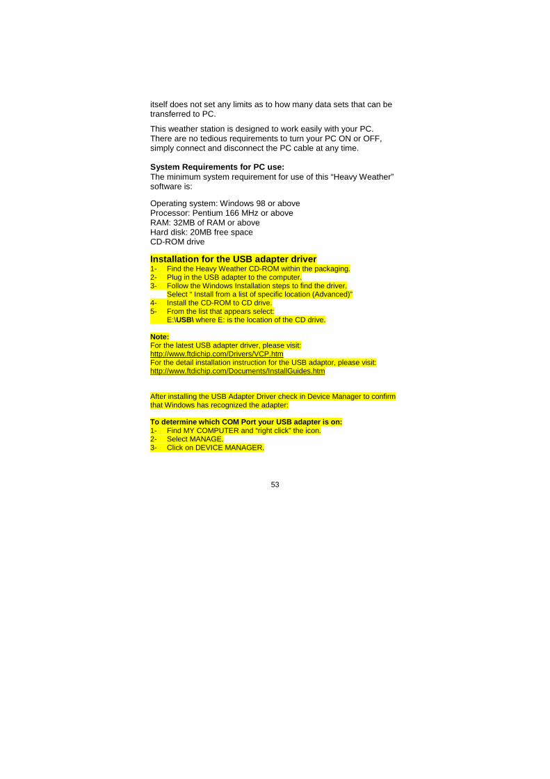
Installation for the USB adapter driver 1- Find the Heavy Weather CD-ROM within the packaging. 2- Plug in the USB adapter to the computer. 3- Follow the Windows Installation steps to find the driver.
Select “ Install from a list of specific location (Advanced)” 4- Install the CD-ROM to CD drive. 5- From the list that appears select: E:\USB\ where E: is the location of the CD drive. Note: For the latest USB adapter driver, please visit: http://www.ftdichip.com/Drivers/VCP.htm For the detail installation instruction for the USB adaptor, please visit: http://www.ftdichip.com/Documents/InstallGuides.htm After installing the USB Adapter Driver check in Device Manager to confirm that Windows has recognized the adapter: To determine which COM Port your USB adapter is on: 1- Find MY COMPUTER and “right click” the icon. 2- Select MANAGE. 3- Click on DEVICE MANAGER.
54
4- You should see COM Ports listed with numbers after them Ex: Com-munications Port (COM 1), USB to Serial Bridge (COM 4).
If you do not see a COM setting, your computer does not recognize your USB driver.
5- If the USB adapter is not on COM port 1, 2, 3 or 4 you will need to change it.
6- Double click the COM Port Ex: (COM 7) this will bring up a Communi-cations Port Properties Box. Click the Port Settings Tab, Click Ad-vanced.
7- Click the Drop Down next to the COM port number and select Com 1, 2, 3, or 4. If they are IN USE see your computer person BEFORE changing.
After configuring the adapter, connect the weather station and open the Heavy Weather software. Click SETUP button and select the proper COM Port. Data should begin to download within a minute or two. Features of the base station: • Receives and displays the DCF77 radio controlled time and date • Display of extensive weather data, in all cases with programmable
alarm functions for certain weather conditions as well as records of all minimum and maximum values along with time and date of their recordings
• Indoor and outdoor temperature and relative humidity displays in degrees Fahrenheit or Celsius (user selectable)
• Indoor and outdoor relative humidity displays • Air pressure reading in inHg or hPa, absolute or relative (user
selectable) • Detailed display of rainfall data in 1 hour, 24 hours, total since last
reset (user selectable in mm or inch) • Wind speed in mph, km/h, m/s, knots or Beaufort (user selectable) • Wind direction display with LCD compass as well as numerical
(e.g. 225°) and abbreviated characters (e.g. SW) • Wind chill temperature display • Dew point temperature display • Weather forecast display by weather icons (sunny, cloudy, rainy) • Weather tendency indicator • Storm warning alarm • LED back light
55
• Simultaneous display of all weather data with individual settings by the user
• COM port for easy connection to your PC • All the weather data from the base station and up to 175 sets of
weather history data with user adjustable measuring intervals can be recorded and uploaded to your PC
Features of the Thermo-Hygro Sensor The thermo-hygro sensor measures the outdoor temperature and relative humidity. It also collects the readings from the rain and wind sensors before transmitting the data to the base station by wireless 433MHz or by the 10 meter cable included in this set. Features of Wind sensor The wind sensor measures wind speed and wind direction and sends the data to thermo-hygro sensor which in turn transmits the data to the base station. Operating power is taken from the ther-mo-hygro sensor using a 10 meter cable connection. Features of Rain sensor The rain sensor measures the rainfall and sends the data to ther-mo-hygro sensor which in turn transmits the data to the base sta-tion. Operating power is taken from the thermo-hygro sensor by a 10 meter cable connection. 3. Safety Notes • Damage caused by failure to comply with this instruction manual
will invalidate any guarantee! The manufacturer and supplier will not be held liable for actions due to failure to comply with this in-struction manual or from data inaccuracies that may occur with this product!
• In case of harm or damage to a person or property caused by improper handling or failure to comply with this instruction manual, the manufacturer and supplier cannot be held liable.
• For reasons of safety and operation, alterations to this device are strictly prohibited.

56
• To operate the weather station, use only supplied adaptor and batteries of the recommended type.
• Do not leave used-up batteries in the device as these may corrode and release chemicals that may damage the unit.
• Inserting batteries in an incorrect polarity will cause damage to this product.
• This product is not a toy kept out of the reach of children.
• Do not depose new or used batteries to fire as they may explosion or release dangerous chemicals.
• This product is not to be used for medical purposes or for public information.
57
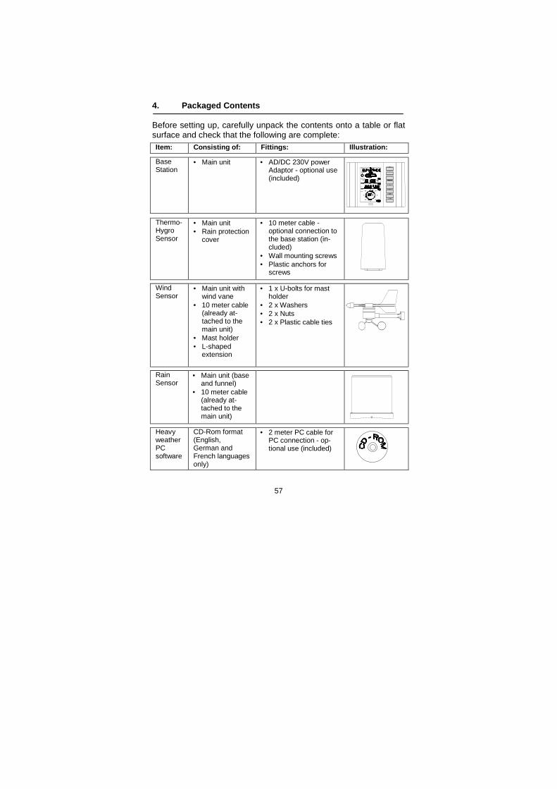
4. Packaged Contents Before setting up, carefully unpack the contents onto a table or flat surface and check that the following are complete:
Item: Consisting of: Fittings: Illustration:
Base Station
• Main unit
• AD/DC 230V power Adaptor - optional use (included)
Thermo-Hygro Sensor
• Main unit • Rain protection
cover
• 10 meter cable - optional connection to the base station (in-cluded)
• Wall mounting screws • Plastic anchors for
screws
Wind Sensor
• Main unit with wind vane
• 10 meter cable (already at-tached to the main unit)
• Mast holder • L-shaped
extension
• 1 x U-bolts for mast holder
• 2 x Washers • 2 x Nuts • 2 x Plastic cable ties
Rain Sensor
• Main unit (base and funnel)
• 10 meter cable (already at-tached to the main unit)
Heavy weather PC software
CD-Rom format (English, German and French languages only)
• 2 meter PC cable for PC connection - op-tional use (included)
58
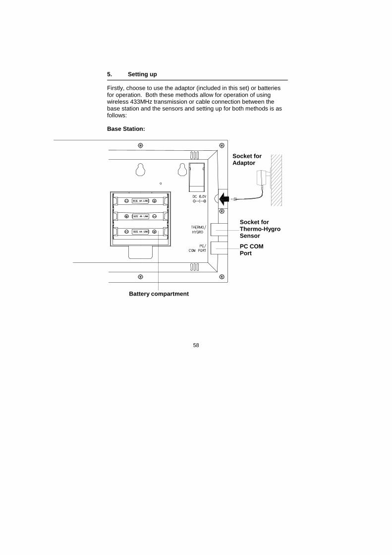
Battery compartment
Socket for Adaptor
5. Setting up Firstly, choose to use the adaptor (included in this set) or batteries for operation. Both these methods allow for operation of using wireless 433MHz transmission or cable connection between the base station and the sensors and setting up for both methods is as follows: Base Station:
Socket for Thermo- Hygro Sensor PC COM Port
59
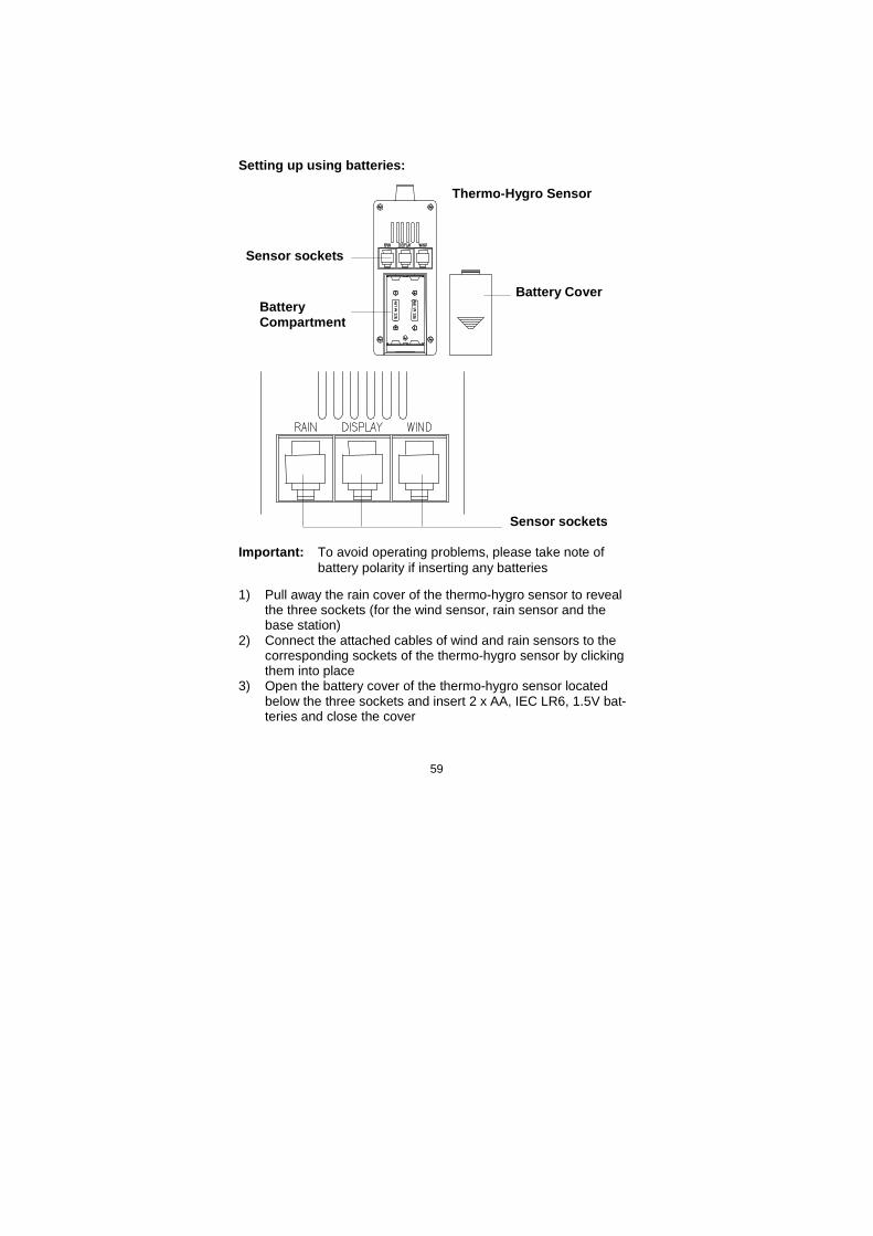
Setting up using batteries: Important: To avoid operating problems, please take note of
battery polarity if inserting any batteries 1) Pull away the rain cover of the thermo-hygro sensor to reveal
the three sockets (for the wind sensor, rain sensor and the base station)
2) Connect the attached cables of wind and rain sensors to the corresponding sockets of the thermo-hygro sensor by clicking them into place
3) Open the battery cover of the thermo-hygro sensor located below the three sockets and insert 2 x AA, IEC LR6, 1.5V bat-teries and close the cover
Battery Compartment
Battery Cover
Thermo -Hygro Sensor
Sensor sockets
Sensor sockets
60
4) Open the base station’s battery cover located at the back of the unit and insert 3 x AA, IEC LR6, 1.5V batteries into the bat-tery compartment and close the battery cover
Setting up using the AC adaptor: 1) Power up all the sensors as described in setting up using bat-
teries above 2) Using the AC adaptor (included), plug it into the mains outlet
and power up the base station by inserting the adaptor jack in-to the 6.0V DC socket located on the side of the base station
Every time the thermo-hygro sensor is powered up (for example after a change of batteries), a random security code is transmitted and this code must be synchronized with the base station to receive weather data. When the base station is powered up, a short beep will sound and all LCD segments will light up for about 5 seconds before it enters into a 15 minute learning mode to learn the sensors security code. After the learning mode (or by pressing the MIN/MAX key at any-time), the base station will start the DCF77 radio controlled time reception. Note for DCF77 Radio Controlled Time: The time and date display is based on the signal provided by a highly accurate Caesium atomic clock operated by the Physikalisch Technische Bundesamt in Braunschweig (Germany). This radio-controlled clock does not only provide for the weather station’s time and date display but also functions as the time source for all of this weather station’s memory and history values using time and date information. LCD backlight: When using the power adaptor or under battery operation, the LCD backlight will switch on for 15 seconds when any key is pressed.
61
6. Operation using cable connection or wireless 433 MHz Cable Connection: Using this method of operation will provide interference free trans-fer of the weather data from the sensors to the base station. The data sending interval from the sensors to the base station will also be more frequent compared to using 433MHz transmission and will result in higher power consumption. Therefore batteries will have a shorter life span for cable connection compared to using 433MHz. To operate using cable connection, simply use the enclosed 10 meter cable and connect the thermo-hygro sensor to the base sta-tion. Once the connection is detected, the base station will automat-ically continue reading the data from the sensor. The user may at any time switch from cable connection to using 433MHz (or vice versa) by simply disconnecting (or connecting) the cable from the base station to the sensor. When the base station detects no cable connection to the sensors, the existing data read-ing interval is changed to the new reading interval, i.e. using cable connection is every 8 seconds data reading interval or from 32 seconds - 128 seconds intervals when using 433MHz (depending on wind speed) Using the AC adaptor to operate the base station will also supply power to the sensor if the cable is connected to it. Batteries used for 433MHz transmission may be left in the sensor when using cable connection for power back-up in case of AC power failure. A loss of power would desynchronize the base station and the sensor and no weather data will be received. To Synchronize the units so that the weather data can be received, press and hold the PLUS(+) for 2 seconds. However in general, batteries that will not be used for long periods should be removed to avoid leakage. Wireless 433MHz transmission: Using 433MHz wireless transmission of weather data from the sensor to the base station will provide users greater freedom as to where units can be positioned without the need to be restricted by cable.

62
Note: If no outdoor weather data is displayed or the signal to the sensors is lost during setting up, mounting, changing of batteries to the sensor or plugging or unplugging cables, simply press and hold the PLUS(+) key for 2 seconds and a short beep will sound to syn-chronize the base station to sensors. Without being synchronized, weather data will not be received.
63
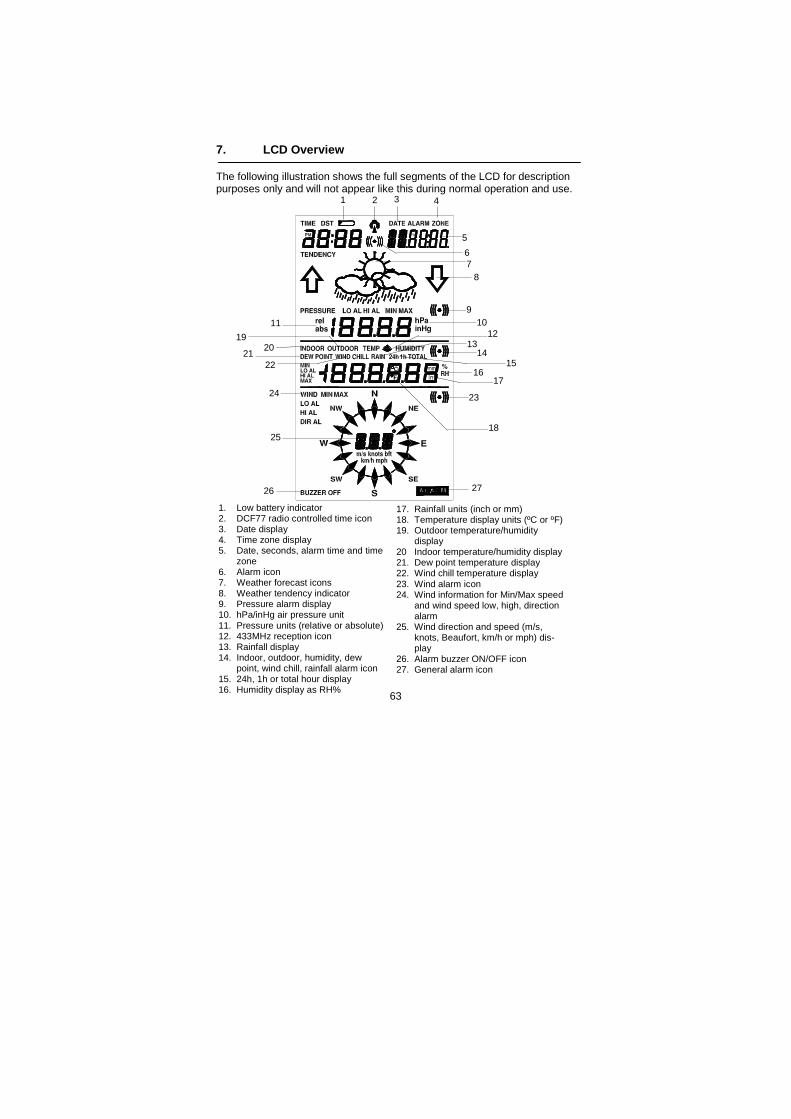
1. Low battery indicator 2. DCF77 radio controlled time icon 3. Date display 4. Time zone display 5. Date, seconds, alarm time and time
zone 6. Alarm icon 7. Weather forecast icons 8. Weather tendency indicator 9. Pressure alarm display 10. hPa/inHg air pressure unit 11. Pressure units (relative or absolute) 12. 433MHz reception icon 13. Rainfall display 14. Indoor, outdoor, humidity, dew
point, wind chill, rainfall alarm icon 15. 24h, 1h or total hour display 16. Humidity display as RH%
17. Rainfall units (inch or mm) 18. Temperature display units (ºC or ºF) 19. Outdoor temperature/humidity
display 20 Indoor temperature/humidity display 21. Dew point temperature display 22. Wind chill temperature display 23. Wind alarm icon 24. Wind information for Min/Max speed
and wind speed low, high, direction alarm
25. Wind direction and speed (m/s, knots, Beaufort, km/h or mph) dis-play
26. Alarm buzzer ON/OFF icon 27. General alarm icon
7. LCD Overview The following illustration shows the full segments of the LCD for description purposes only and will not appear like this during normal operation and use.
16
1 2 3 4
5
6 7 8
9 10
13 12
14 15
17
23
11
19 20
22 21
18
24
25
26 27
64
8. Function test:
Once the weather station is powered up, perform a function test by checking that the weather data is received. To do this, press the either DISPLAY, PRESSURE or WIND keys to toggle through the relevant LCD sections:
1) Indoor temperature and humidity 2) Outdoor temperature and humidity 3) Outdoor wind chill 4) Dew point 5) Rainfall 24 hour 6) Rainfall 1hour 7) Rainfall Total 8) Relative and absolute pressure 9) Wind speed, wind direction and wind direction in degrees
If any readings cannot be received from the sensors, lines (- - -) will be displayed in the respective weather sections of the LCD. In this case, check that all cables are correctly inserted into the correct sockets and press and hold the PLUS(+) key for 2 seconds and a short beep will sound to synchronize the base station to the sen-sors otherwise no weather data will be received. Some weather readings such as wind speed and direction may not appear immediately on the LCD if the wind-fan or vane of the wind sensor is moved. This is due to the set reading time intervals for the wind readings. However the current wind speed or direction will be displayed once the time reading interval is reached. For rainfall, the interval readings may take up to 2 minutes before the data is displayed on the LCD. 9. Mounting
Important Note Prior to drilling mounting holes and permanently affixing any of the units, please ensure the following points are considered: • Cable lengths of the units meet with your distance require-
ments at the point of fixing
65
• Signals from the sensors can be received by the base station at points of mounting
• Radio controlled time signal can be received at the point of mounting
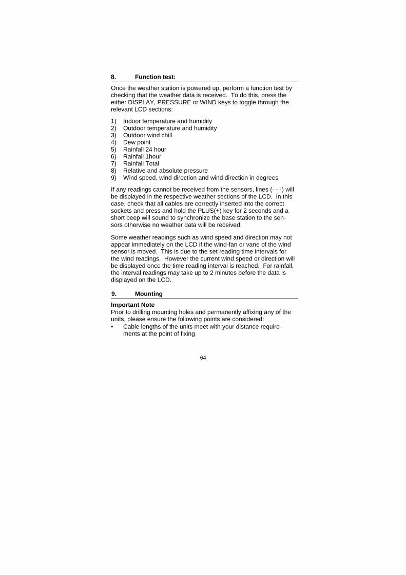
Base Station With two foldable legs at the back of the unit, the base station can be placed onto any flat surface or wall mounted at the desired loca-tion by the hanging holes also at the back of the unit. It is important to check that the 433MHz (if using wireless connection) and the DCF77 radio controlled time signal can be received before perma-nently mounting any of the units. Should the base station not dis-play the 433MHz weather data from the sensors or the radio con-trolled time from the desired location, then relocate the units. Once the signals are received, the system can be affixed. Also if you have selected to use cable connection, ensure that distances can reach all desired locations before affixing any unit permanently Mounting the Wind Sensor The remote wind speed sensor can be mounted two ways: • With the use of screws • Using nylon straps Mounting with screws
Horizontal panel
Wind vane
Fixed with screw
66
1. Unlock the mounting bracket from the remote wind speed sen-sor leaving the wire going through the bracket.
2. Place the mounting bracket over the desired location. 3. Through the two screw holes of the bracket, mark the mounting
surface with a pencil. 4. Screw the mounting bracket onto the mounting surface. En-
sure that the screws are tight against the bracket. 5. Slide the remote wind speed sensor onto the bracket making
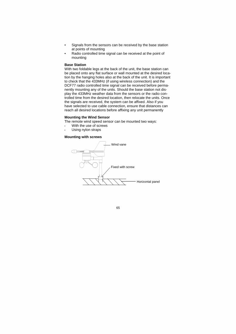
sure to lock it in place. MOUNTING WITH NYLON STRAPS 1. Unlock the mounting bracket from the remote wind speed sen-
sor leaving the wire going through the bracket. 2. Place two nylon straps through the slots on the mounting
bracket. 3. Place the remote wind speed sensor in your desired location. 4. Fasten the two nylon straps securely around the mounting
location. 5. Slide the remote wind speed sensor onto the bracket making
sure to lock it in place. Once the wind sensor is fixed onto the mast, connect the cable to the corresponding thermo-hygro sensor socket so that operating power supply can be received and data can be transmitted to the base station.
Vertical mast
Wind fan Fixed with Nylon strap
67
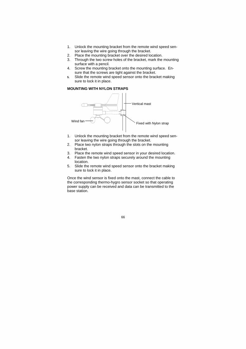
Mounting the Rain Sensor For best results, the rain sensor should be securely mounted onto a horizontal surface about 1 meter above the ground and in an open area away from trees or other coverings where rainfall may be reduced causing inaccurate readings.
When securing into place, check that rain excess will not collect and store at the base of the unit but can flow out between the base and the mounting surface (test by pouring clean water).
After mounting the rain sensor, connect the cable to the thermo-hygro sensor at the corresponding socket so power supply can be received and data be transmitted to the base station
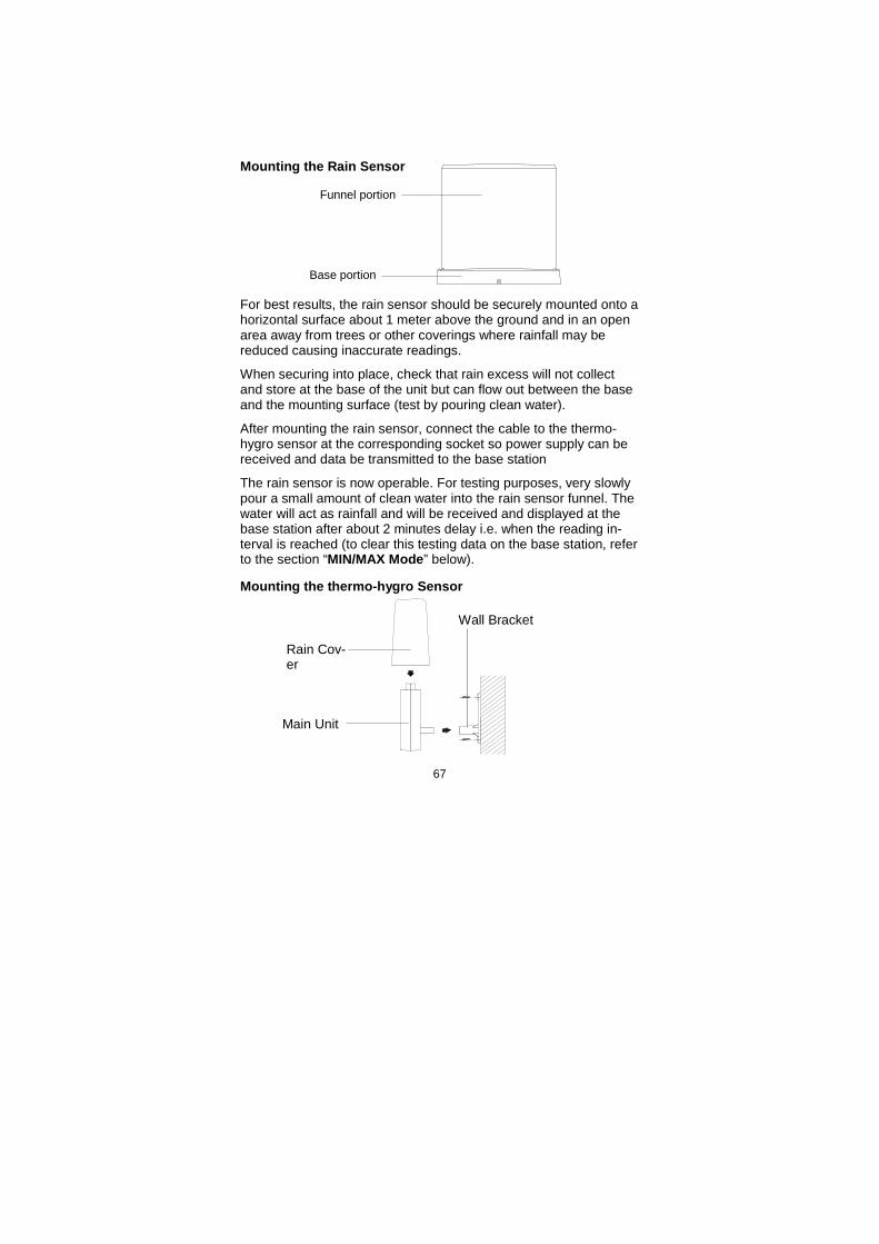
The rain sensor is now operable. For testing purposes, very slowly pour a small amount of clean water into the rain sensor funnel. The water will act as rainfall and will be received and displayed at the base station after about 2 minutes delay i.e. when the reading in-terval is reached (to clear this testing data on the base station, refer to the section “MIN/MAX Mode ” below). Mounting the thermo-hygro Sensor
Base portion
Funnel portion
Rain Cov-er
Wall Bracket
Main Unit
68
An ideal mounting place for the thermo-hygro sensor would be the outer wall beneath the extension of a roof, as this will protect the sensor from direct sunlight and other extreme weather conditions. To wall mount, use the 2 screws to affix the wall bracket to the desired wall, plug in the thermo-hygro sensor to the bracket and secure both parts by the use of the supplied screw and ensure that the cables from the wind and rain sensors are correctly plugged in otherwise data transmission errors could occur. 10. Resetting & factory settings: As previously mentioned, in the event of a power reset to the sen-sor (for example a change of batteries), the base station has to synchronize to the sensor again otherwise no weather data will be received. To do this, simply press and hold the PLUS(+) key for 2 seconds and a short beep will sound to synchronize the base sta-tion to the sensor. When the units are synchronized, the data will be received again and the base station will return to normal opera-tion mode. Do not reset the power of the base station otherwise all 175 sets of recorded weather history data for transferring to the PC will be lost (for full details of PC use, please see PC user manual in the en-closed Heavy Weather CD-ROM). However if you wish to make a full reset of the base station and return to the original factory settings, simultaneously press and hold the PRESSURE and WIND keys for about 5 seconds. The base station will beep once and the entire LCD will light up for 5 seconds and go back to the original factory settings. This process with clear all previous user defined values and all weather history recordings.
69
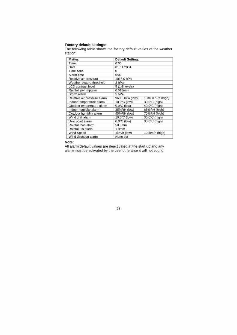
Factory default settings: The following table shows the factory default values of the weather station:
Matter: Default Setting: Time 0:00 Date 01.01.2001 Time zone 0 Alarm time 0:00 Relative air pressure 1013.0 hPa Weather-picture threshold 3 hPa LCD contrast level 5 (1-8 levels) Rainfall per impulse 0.518mm Storm alarm 5 hPa Relative air pressure alarm 960.0 hPa (low) 1040.0 hPa (high) Indoor temperature alarm 10.0ºC (low) 30.0ºC (high) Outdoor temperature alarm 0.0ºC (low) 40.0ºC (high) Indoor humidity alarm 35%RH (low) 65%RH (high) Outdoor humidity alarm 45%RH (low) 70%RH (high) Wind chill alarm 10.0ºC (low) 30.0ºC (high) Dew point alarm 0.0ºC (low) 30.0ºC (high) Rainfall 24h alarm 50.0mm Rainfall 1h alarm 1.0mm Wind Speed 1km/h (low) 100km/h (high) Wind direction alarm None set
Note: All alarm default values are deactivated at the start up and any alarm must be activated by the user otherwise it will not sound.
70
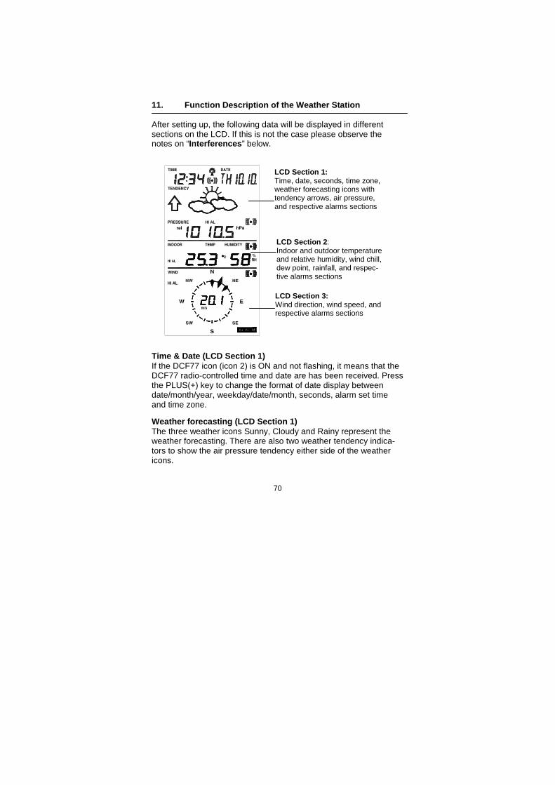
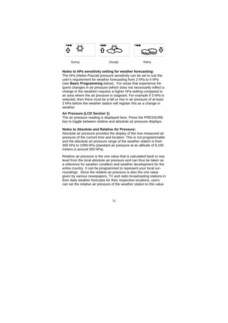
11. Function Description of the Weather Station After setting up, the following data will be displayed in different sections on the LCD. If this is not the case please observe the notes on “Interferences ” below. Time & Date (LCD Section 1) If the DCF77 icon (icon 2) is ON and not flashing, it means that the DCF77 radio-controlled time and date are has been received. Press the PLUS(+) key to change the format of date display between date/month/year, weekday/date/month, seconds, alarm set time and time zone. Weather forecasting (LCD Section 1) The three weather icons Sunny, Cloudy and Rainy represent the weather forecasting. There are also two weather tendency indica-tors to show the air pressure tendency either side of the weather icons.
LCD Section 1: Time, date, seconds, time zone, weather forecasting icons with tendency arrows, air pressure, and respective alarms sections
LCD Section 2 : Indoor and outdoor temperature and relative humidity, wind chill, dew point, rainfall, and respec-tive alarms sections
LCD Section 3: Wind direction, wind speed, and respective alarms sections
71
Sunny Rainy Cloudy
Notes to hPa sensitivity setting for weather foreca sting: The hPa (Hekto-Pascal) pressure sensitivity can be set to suit the user’s requirement for weather forecasting from 2 hPa to 4 hPa (see Basic Programming below). For areas that experience fre-quent changes in air pressure (which does not necessarily reflect a change in the weather) requires a higher hPa setting compared to an area where the air pressure is stagnant. For example if 3 hPa is selected, then there must be a fall or rise in air pressure of at least 3 hPa before the weather station will register this as a change in weather.
Air Pressure (LCD Section 1) The air pressure reading is displayed here. Press the PRESSURE key to toggle between relative and absolute air pressure displays. Notes to Absolute and Relative Air Pressure: Absolute air pressure provides the display of the true measured air pressure of the current time and location. This is not programmable and the absolute air pressure range of the weather station is from 300 hPa to 1099 hPa (standard air pressure at an altitude of 9,100 meters is around 300 hPa). Relative air pressure is the one value that is calculated back to sea level from the local absolute air pressure and can thus be taken as a reference for weather condition and weather development for the entire country. It can be programmed to represent your local sur-roundings. Since the relative air pressure is also the one value given by various newspapers, TV and radio broadcasting stations in their daily weather forecasts for their respective locations, users can set the relative air pressure of the weather station to this value
72
to represent readings your their area (see Basic Programming Modes below). Weather Data (LCD Section 2) Indoor temperature and humidity are displayed simultaneously in this section. Use the DISPLAY key to toggle through the displays for other weather information: - Outdoor temperature/humidity - Outdoor wind chill - Outdoor dew point - Rainfall 24h - Rainfall 1h - Rainfall total. Notes to Dewpoint and Windchill: Air can at a certain temperature only carry a certain amount of water (water vapor), which also increases and decreases with tem-perature. If the air temperature decreases below the so called dew-point (saturation point), the excessive water vapor will condense and fall out in form of dew, fog or rain. At a temperature of e.g. 15°C and a relative humidity of 50% the dewpoint wi ll be about 5°C, at 80% humidity about 12°C. At a relative humidity of 100% satura-tion is reached, i.e. the dewpoint is 15°C. At a dew point below freezing the fallout will become frost or snow. Windchill has been introduced for battle planning during World War II. It represents not the real measured but the one temperature a person feels in open area under the influence of wind and cold. Windchill is laid out in tables for various temperatures and wind speeds. At an outdoor temperature of e.g. 8°C and c alm winds a person moving at a speed of 6 m/s will already feel a windchill tem-perature of 0°C. Wind Data (LCD Section 3) The current wind direction will be displayed on the LCD compass on the wind section. Press the WIND key to toggle between wind direction as numerical (e.g. 225°) and abbreviated characters (e.g.
73
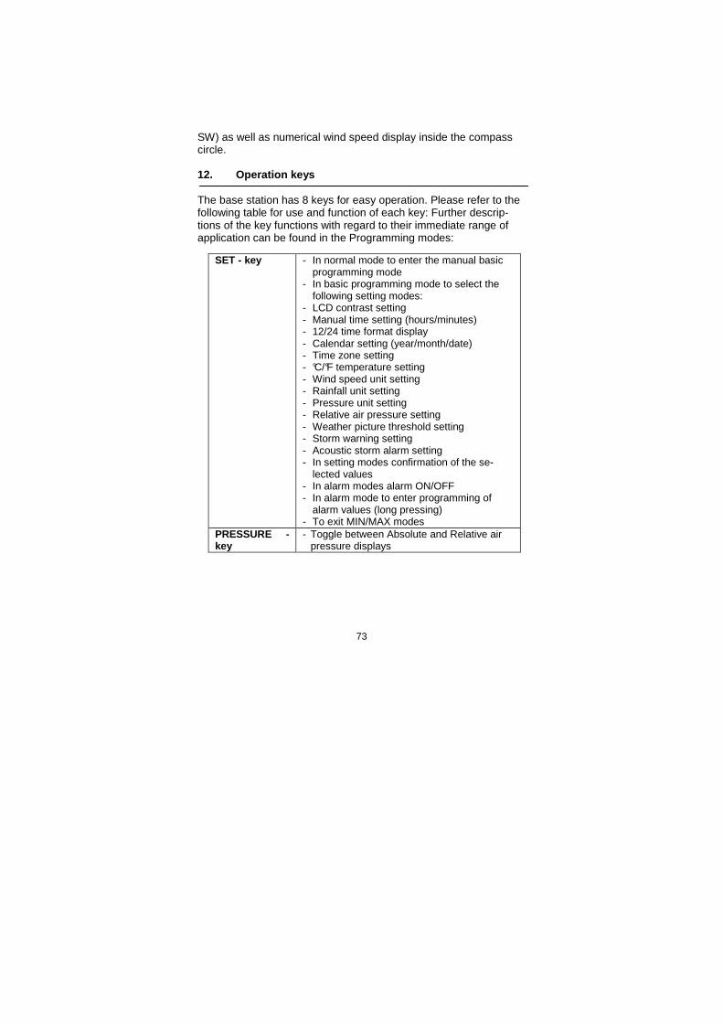
SW) as well as numerical wind speed display inside the compass circle. 12. Operation keys The base station has 8 keys for easy operation. Please refer to the following table for use and function of each key: Further descrip-tions of the key functions with regard to their immediate range of application can be found in the Programming modes:
SET - key - In normal mode to enter the manual basic programming mode
- In basic programming mode to select the following setting modes:
- LCD contrast setting - Manual time setting (hours/minutes) - 12/24 time format display - Calendar setting (year/month/date) - Time zone setting - °C/°F temperature setting - Wind speed unit setting - Rainfall unit setting - Pressure unit setting - Relative air pressure setting - Weather picture threshold setting - Storm warning setting - Acoustic storm alarm setting - In setting modes confirmation of the se-
lected values - In alarm modes alarm ON/OFF - In alarm mode to enter programming of
alarm values (long pressing) - To exit MIN/MAX modes
PRESSURE - key
- Toggle between Absolute and Relative air pressure displays
74
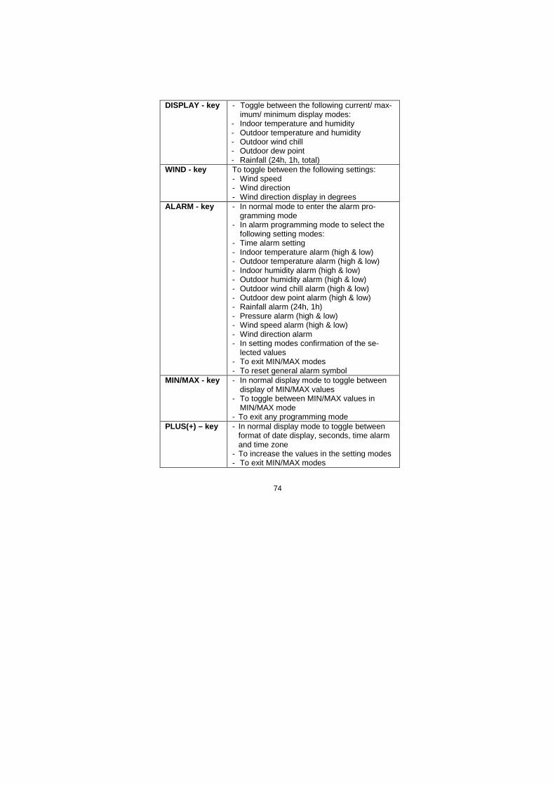
DISPLAY - key - Toggle between the following current/ max-imum/ minimum display modes:
- Indoor temperature and humidity - Outdoor temperature and humidity - Outdoor wind chill - Outdoor dew point - Rainfall (24h, 1h, total)
WIND - key To toggle between the following settings: - Wind speed - Wind direction - Wind direction display in degrees
ALARM - key - In normal mode to enter the alarm pro-gramming mode
- In alarm programming mode to select the following setting modes:
- Time alarm setting - Indoor temperature alarm (high & low) - Outdoor temperature alarm (high & low) - Indoor humidity alarm (high & low) - Outdoor humidity alarm (high & low) - Outdoor wind chill alarm (high & low) - Outdoor dew point alarm (high & low) - Rainfall alarm (24h, 1h) - Pressure alarm (high & low) - Wind speed alarm (high & low) - Wind direction alarm - In setting modes confirmation of the se-
lected values - To exit MIN/MAX modes - To reset general alarm symbol
MIN/MAX - key - In normal display mode to toggle between display of MIN/MAX values
- To toggle between MIN/MAX values in MIN/MAX mode
- To exit any programming mode PLUS(+) – key - In normal display mode to toggle between
format of date display, seconds, time alarm and time zone
- To increase the values in the setting modes - To exit MIN/MAX modes
75
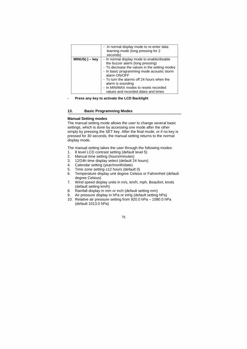
- In normal display mode to re-enter data learning mode (long pressing for 2 seconds)
MINUS(-) – key - In normal display mode to enable/disable the buzzer alarm (long pressing)
- To decrease the values in the setting modes - In basic programming mode acoustic storm
alarm ON/OFF - To turn the alarms off 24 hours when the
alarm is sounding - In MIN/MAX modes to resets recorded
values and recorded dates and times
• Press any key to activate the LCD Backlight 13. Basic Programming Modes Manual Setting modes The manual setting mode allows the user to change several basic settings, which is done by accessing one mode after the other simply by pressing the SET key. After the final mode, or if no key is pressed for 30 seconds, the manual setting returns to the normal display mode. The manual setting takes the user through the following modes: 1. 8 level LCD contrast setting (default level 5) 2. Manual time setting (hours/minutes) 3. 12/24h time display select (default 24 hours) 4. Calendar setting (year/month/date) 5. Time zone setting ±12 hours (default 0) 6. Temperature display unit degree Celsius or Fahrenheit (default
degree Celsius) 7. Wind speed display units in m/s, km/h, mph, Beaufort, knots
(default setting km/h) 8. Rainfall display in mm or inch (default setting mm) 9. Air pressure display in hPa or inHg (default setting hPa) 10. Relative air pressure setting from 920.0 hPa – 1080.0 hPa
(default 1013.0 hPa)
76
11. Weather forecast sensitivity setting 2 hPa – 4 hPa (default 4 hPa)
12. Storm warning sensitivity setting 3 hPa - 9 hPa (default 5 hPa) 13. Acoustic storm alarm On/OFF (default ON) To change any of the above values, once your are in the setting mode, use the PLUS(+) or MINUS(-) keys to select the values fol-lowed by the SET key to enter the next setting. Continue to press the SET key to toggle through the setting mode until the LCD re-turns to the normal display mode or press the MIN/MAX key at any time to exit. Note! Keeping the PLUS(+) or MINUS(-) key depressed when setting certain units in the manual setting mode will increase/decrease digits in greater steps. Manual time setting The base station will continue to scan for the radio controlled time signal from 2am-6 am each day (winter time) or from 3am-6am (summer time) despite it being manually set. During reception at-tempts the DCF tower icon will flash.
• If reception has been unsuccessful, then the DCF77 tower icon will not appear but reception will still be attempted the following hour within the time frame
• If reception has been successful, the received time and date will overwrite the manually set time and date and no further re-ception is attempted until the following day
14. MIN/MAX Programming Modes
MIN/MAX display Mode The MIN/MAX Mode provides the user with information about the MIN/MAX values of all weather data together with the time and date at which these values were recorded.
77
Entering each MIN/MAX mode In the normal display mode for e.g. the indoor temperature and humidity, press MIN/MAX key to toggle the display between the maximum, minimum and current records. While the maximum or minimum values are shown press the DISPLAY key once to show the time and date that value was received. Now press the MIN/MAX key to toggle from the minimum and maximum readings and the time and dates the records were received are also shown. Still in the MIN/MAX mode (where the time and date for a value are shown), press the DISPLAY key to move through each respective unit as follows: • Indoor temperature (max or min with time and date) • Indoor humidity (max or min with time and date) • Outdoor temperature (max or min with time and date) • Outdoor humidity (max or min with time and date) • Outdoor wind chill (max or min with time and date) • Outdoor dew point (max or min with time and date) • Rainfall 24 hours (max or min with time and date) • Rainfall 1 hour (max or min with time and date) • Rainfall total (max only with time and date)
When in any of the above modes, press the MIN/MAX key to toggle between the maximum or minimum values of those records and their respective time and dates will also be shown. For the wind and pressure minimum and maximum readings, the same would apply except that the WIND or PRESSURE keys would be used instead of the DISPLAY KEY. Exiting the MIN/MAX modes If the maximum and minimum modes with times and dates are displayed, press the PLUS(+) key twice to return the normal display mode. Resetting the MIN/MAX records Whilst in the minimum or maximum mode, the time and dates are also displayed along with the recorded values. If the MINUS(-) key is pressed whilst any of these values are displayed, that particular
78
minimum or maximum record will be reset to current reading to-gether with the current time and date with the exception of the fol-lowing: � The first case is Rainfall Total, which has neither maximum nor
minimum records since it will show only the total rainfall. Press-ing the MINUS(-) key, will reset the rainfall total value to zero and the time recording to current time.
� The second case is Rainfall 24h or 1h, which records maxi-mum rain count only for these respective times. Pressing the MINUS(-) key in either of these two modes will reset the rain count to the current rain count and time and date.
15. Alarm Programming Modes
Alarm Modes As well as the normal time alarm, this feature will allow users to set a range of specific alarms to meet specific weather and tempera-ture conditions set by the user. The weather station allows for the following 13 alarms modes to be set:
1. Time alarm 2. Indoor temperature high alarm and low alarm 3. Outdoor temperature high alarm and low alarm 4. Indoor humidity high alarm and low alarm 5. Outdoor humidity high alarm and low alarm 6. Wind chill high alarm and low alarm 7. Dew point alarm high alarm and low alarm 8. Rainfall 24h alarm 9. Rainfall 1h alarm 10. Pressure high alarm and low alarm 11. Wind speed high alarm and low alarm 12. Wind direction alarm 13. Storm warning alarm
Setting Alarms: For alarm setting, press the ALARM key once whilst in normal op-eration mode to enter the normal alarm time and by further pressing the ALARM key will toggle through each of the alarm modes:
79
Note: The alarm icon will automatically appear upon press ing the SET key to tell the user the alarm is activated. Furt her pressing the SET key will deactivate/reactivate the alarm. Time alarm setting 1) Press the ALARM key to enter the normal time alarm 2) Press and hold the SET key to enter the alarm hour time set
mode (the hour digits will flash) and set the desired hour by us-ing the PLUS(+) or MINUS(-) keys
3) Press the SET key to enter the alarm minute time set mode (the minutes digits will flash) and set the desired minutes using the PLUS(+) or MINUS(-) keys
4) Press ALARM key to confirm followed by the MIN/MAX key to return to the normal display mode.
Indoor temperature high alarm and low alarm setting 1) Press the ALARM key to enter the normal time alarm 2) Press the ALARM key again to enter indoor temperature high
alarm set mode 3) Press and hold the SET key to enter the indoor temperature
high setting values (digits will start flashing) and set the desired indoor temperature high by using the PLUS(+) or MINUS (-) keys
4) Press ALARM key to confirm and press the MIN/MAX key to return to the normal display mode or press the ALARM once more to toggle to the indoor temperature low alarm set mode.
5) Press and hold the SET key to enter the indoor temperature low setting values (temperature digits will start flashing) and set the desired indoor temperature low by using the PLUS(+) or MI-NUS(-) keys
6) Press ALARM key to confirm and press the MIN/MAX key to return the normal display mode or press the ALARM once more to toggle to another alarm setting mode.
Outdoor temperature high alarm and low alarm settin g 1) Press the ALARM key to enter the normal time alarm
80
2) Continue to press the ALARM key until you reach the outdoor temperature high alarm set mode
3) Press and hold the SET key to enter the outdoor temperature high setting values (temperature digits will start flashing) and set the desired outdoor temperature high by using the PLUS(+) or MINUS (-) keys
4) Press ALARM key to confirm and press the MIN/MAX key to return to the normal display mode or press the ALARM once more to toggle to the outdoor temperature low alarm set mode.
5) Press and hold the SET key to enter the outdoor temperature low setting values (digits will start flashing) and set the desired outdoor temperature low by using the PLUS(+) or MINUS(-) keys
6) Press ALARM key to confirm and press the MIN/MAX key to return the normal display mode or press the ALARM once more to toggle to another alarm setting mode.
Indoor humidity high alarm and low alarm setting 1) Press the ALARM key to enter the normal time alarm 2) Continue to press the ALARM key until you reach the indoor
humidity high alarm set mode 3) Press and hold the SET key to enter the indoor humidity high
setting values (% digits will start flashing) and set the desired indoor humidity high by using the PLUS(+) or MINUS (-) keys
4) Press ALARM key to confirm and press the MIN/MAX key to return to the normal display mode or press the ALARM once more to toggle to the indoor humidity low alarm set mode.
5) Press and hold the SET key to enter the indoor humidity low setting values (digits will start flashing) and set the desired in-door humidity low by using the PLUS(+) or MINUS(-) keys
6) Press ALARM key to confirm and press the MIN/MAX key to return the normal display mode or press the ALARM once more to toggle to another alarm setting mode.
Outdoor humidity high alarm and low alarm setting 1) Press the ALARM key to enter the normal time alarm 2) Continue to press the ALARM key until you reach the outdoor
humidity high alarm set mode
81
3) Press and hold the SET key to enter the outdoor humidity high setting values (digits will start flashing) and set the desired out-door humidity high by using the PLUS(+) or MINUS (-) keys
4) Press ALARM key to confirm and press the MIN/MAX key to return to the normal display mode or press the ALARM key once more to toggle to the outdoor humidity low alarm set mode.
5) Press and hold the SET key to enter the outdoor humidity low setting values (digits will start flashing) and set the desired out-door humidity low by using the PLUS(+) or MINUS(-) keys
6) Press ALARM key to confirm and press the MIN/MAX key to return the normal display mode or press the ALARM once more to toggle to the to enter another alarm setting mode.
Wind chill high alarm and low alarm setting 1) Press the ALARM key to enter the normal time alarm 2) Continue to press the ALARM key until you reach the wind chill
high alarm set mode 3) Press and hold the SET key to enter the wind chill high setting
values (digits will start flashing) and set the desired wind chill high by using the PLUS(+) or MINUS (-) keys
4) Press ALARM key to confirm and press the MIN/MAX key to return to the normal display mode or press the ALARM key once more to toggle to the wind chill low alarm set mode.
5) Press and hold the SET key to enter the wind chill low setting values (digits will start flashing) and set the desired wind chill low by using the PLUS(+) or MINUS(-) keys
6) Press ALARM key to confirm and press the MIN/MAX key to return the normal display mode or press the ALARM once more to toggle to another alarm setting mode.
Dew point alarm high alarm and low alarm setting 1) Press the ALARM key to enter the normal time alarm 2) Continue to press the ALARM key until you reach the dew point
high alarm set mode 3) Press and hold the SET key to enter the dew point setting val-
ues (digits will start flashing) and set the desired dew point high by using the PLUS(+) or MINUS (-) keys
82
4) Press ALARM key to confirm and press the MIN/MAX key to return to the normal display mode or press the ALARM key once more to toggle to the dew point low alarm set mode.
5) Press and hold the SET key to enter the dew point low setting values (digits will start flashing) and set the desired dew point low by using the PLUS(+) or MINUS(-) keys
6) Press ALARM key to confirm and press the MIN/MAX key to return the normal display mode or press the ALARM once more to toggle to another alarm setting mode.
Rainfall 24h alarm setting 1) Press the ALARM key to enter the normal time alarm 2) Continue to press the ALARM key until you reach the rain 24
hour alarm set mode 3) Press and hold the SET key to enter the rain setting values
(digits will start flashing) and set the desired rain values by us-ing the PLUS(+) or MINUS (-) keys
4) Press ALARM key to confirm and press the MIN/MAX key to return to the normal display mode or press the ALARM key once more to toggle to another alarm setting mode.
Rainfall 1h alarm setting 1) Press the ALARM key to enter the normal time alarm 2) Continue to press the ALARM key until you reach the rain 1
hour alarm set mode 3) Press and hold the SET key to enter the rain setting values
(digits will start flashing) and set the desired rain values by us-ing the PLUS(+) or MINUS (-) keys
4) Press ALARM key to confirm and press the MIN/MAX key to return to the normal display mode or press the ALARM key once more to another alarm setting mode.
Pressure high alarm and low alarm setting 1) Press the ALARM key to enter the normal time alarm 2) Continue to press the ALARM key until you reach the pressure
high alarm set mode
83
3) Press and hold the SET key to enter the pressure setting values (digits will start flashing) and set the desired pressure high by using the PLUS(+) or MINUS (-) keys
4) Press ALARM key to confirm and press the MIN/MAX key to return to the normal display mode or press the ALARM key once more to toggle to the pressure low alarm set mode.
5) Press and hold the SET key to enter the pressure low setting values (digits will start flashing) and set the desired pressure low by using the PLUS(+) or MINUS(-) keys
6) Press ALARM key to confirm and press the MIN/MAX key to return to the normal display mode or press the ALARM once more to toggle to another alarm setting mode.
Wind speed high alarm and low alarm setting 1) Press the ALARM key to enter the normal time alarm 2) Continue to press the ALARM key until you reach the wind
speed high alarm set mode 3) Press and hold the SET key to enter the wind speed setting
values (digits will start flashing) and set the desired wind speed high by using the PLUS(+) or MINUS (-) keys
4) Press ALARM key to confirm and press the MIN/MAX key to return to the normal display mode or press the ALARM key once more to toggle to the wind speed low alarm set mode.
5) Press and hold the SET key to enter the wind speed low setting values (digits will start flashing) and set the desired pressure low by using the PLUS(+) or MINUS(-) keys
6) Press ALARM key to confirm and press the MIN/MAX key to return the normal display mode or press the ALARM once more to toggle to another alarm setting mode.
Wind direction alarm setting 1) Press the ALARM key to enter the normal time alarm 2) Continue to press the ALARM key until you reach the wind di-
rection alarm set mode 3) Press and hold the SET key to enter the wind direction setting
values.
84
4) Using the PLUS(+) or MINUS (-) keys select the desired wind direction and use the SET key to confirm or cancel each direc-tion input
5) Press ALARM key to confirm and press the MIN/MAX key to return the normal display mode or press the ALARM once more to toggle to another alarm setting mode.
Storm warning alarm setting Unlike the other weather alarms, the storm warning alarm is set by entering the main manual setting mode as follows: 1) Press the SET key to enter the manual setting mode 2) Continue to press the SET key until the Storm warning icon
flashes (tendency arrow flashing downwards with the pressure values flashing)
3) Set the desired hPa pressure value (3 hPa - 9 hPa) using the PLUS(+) or MINUS(-) keys
4) Press the MIN/MAX key to confirm and return to the normal display.
Storm warning alarm ON/OFF After storm warning alarm setting, the next mode to appear after pressing the SET key is the storm warning ON/OFF. Use the PLUS(+) or MINUS(-) key to change the status to AON or AOFF. Default setting is ON: Should the air pressure drop equal or below the pre-set hPa value within the last 6 hour period, then the downward tendency arrow will flash as an indication of possible storm. The base station will take hourly measurements as a point of reference. The storm-warning indicator will stop flashing once the air pressure becomes more stable. Master Alarm – BUZZER OFF The time and all the weather alarms may have buzzer sound set to OFF by holding the MINUS(-) key down for about 3 seconds in normal display mode and the BUZZER OFF icon appears on the bottom left of the LCD. When the BUZZER OFF is displayed, the time and all other weather alarms when activated will only flash but
85
not sound regardless if that particular alarm has been set to the ON. To deactivate the BUZZER OFF, press the MINUS(-) key once more. General Alarm Icon The general alarm icon on the bottom right corner of the LCD will appear when any weather alarm is activated to show the user that a set weather condition has been reached. The activated alarm can be determined by checking the set alarm values against the MIN/MAX values reached. To deactivate the general weather alarm icon, press the ALARM key. Important When entering the alarm set mode for a specific weather or tem-perature condition, the corresponding alarm is automatically enabled (ON) when the SET key is pressed, regardless of its pre-vious setting and the alarm value will flash to indicate that it has been activated. Press the ALARM key to confirm the setting and continue pressing the ALARM key to toggle through each alarm mode until it returns to the normal display mode or press the MIN/MAX key at any time to exit the alarm setting modes. When a set weather alarm condition has been activated, that par-ticular alarm will sound and flash for approximately 2 minutes but will continue to flash until weather conditions have become more steady. Weather Alarms The weather alarms are settable for when certain weather condi-tions are met according to the users requirements. For example, the user can set the thresholds for the outdoor temperature to +40°C (high) and -10°C (low), whilste only enabling the high alarm and disabling the low alarm (i.e. temperatures <-10°C won’t trigger alarm, but temperatures >+40°C will).
86
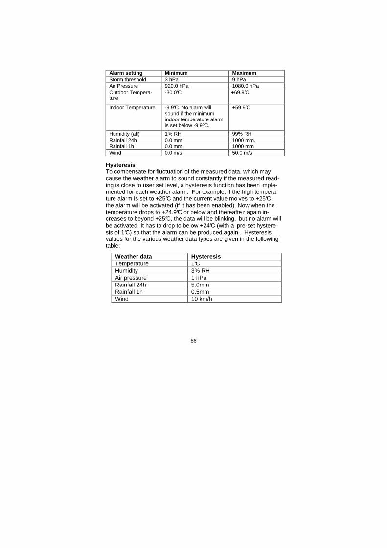
Alarm setting Minimum Maximum Storm threshold 3 hPa 9 hPa Air Pressure 920.0 hPa 1080.0 hPa Outdoor Tempera-ture
-30.0°C +69.9°C
Indoor Temperature -9.9°C. No alarm will sound if the minimum indoor temperature alarm is set below -9.9ºC.
+59.9°C
Humidity (all) 1% RH 99% RH Rainfall 24h 0.0 mm 1000 mm. Rainfall 1h 0.0 mm 1000 mm Wind 0.0 m/s 50.0 m/s
Hysteresis To compensate for fluctuation of the measured data, which may cause the weather alarm to sound constantly if the measured read-ing is close to user set level, a hysteresis function has been imple-mented for each weather alarm. For example, if the high tempera-ture alarm is set to +25°C and the current value mo ves to +25°C, the alarm will be activated (if it has been enabled). Now when the temperature drops to +24.9°C or below and thereafte r again in-creases to beyond +25°C, the data will be blinking, but no alarm will be activated. It has to drop to below +24°C (with a pre-set hystere-sis of 1°C) so that the alarm can be produced again . Hysteresis values for the various weather data types are given in the following table:
Weather data Hysteresis Temperature 1°C Humidity 3% RH Air pressure 1 hPa Rainfall 24h 5.0mm Rainfall 1h 0.5mm Wind 10 km/h
87
16. Auto memory for stored values The base station has a memory back up system, which is used to memorize user-defined settings for when the batteries are changed or if a power failure occurs. User defined units are automatically updated each time these are changed. The base station will me-morize the following user defined units:
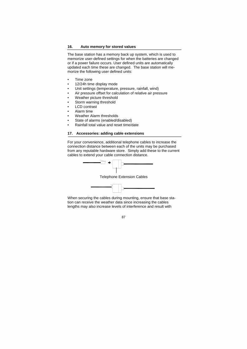
• Time zone • 12/24h time display mode • Unit settings (temperature, pressure, rainfall, wind) • Air pressure offset for calculation of relative air pressure • Weather picture threshold • Storm warning threshold • LCD contrast • Alarm time • Weather Alarm thresholds • State of alarms (enabled/disabled) • Rainfall total value and reset time/date 17. Accessories: adding cable extensions For your convenience, additional telephone cables to increase the connection distance between each of the units may be purchased from any reputable hardware store. Simply add these to the current cables to extend your cable connection distance.
When securing the cables during mounting, ensure that base sta-tion can receive the weather data since increasing the cables lengths may also increase levels of interference and result with
Telephone Extension Cables
88
reception difficulties. Interference levels will greatly depend on the surrounding area for example setting up on or near metal piping may considerably reduce reception. For best results, do not to add more than 10 meters of extension cable from item to item onto the existing cable lengths as this may reduce reception levels. Again, reception and interference levels will greatly depend on the surrounding environment at your point of mounting. Note: It is important to keep all the connected extension heads away from rain, moisture and other extreme weather conditions as exposure can cause short circuits and damage to this item. 18. Changing batteries: Battery change only in the thermo-hygro-sensor: 1. Open the battery cover 2. Remove the old batteries and insert with new ones of the rec-
ommended type and replace the cover Once the sensor is powered up, press and hold the PLUS(+) key for approx. 2 seconds in the normal display mode, the base station will sound a short beep and synchronize to the sensor otherwise no weather data will be received. Battery change only in the base station: 1. Connect power adaptor to base station and power outlet. 2. Open the battery cover located at the back of the base station. 3. Remove the old batteries, insert with new ones of the recom-
mended type and replace the cover This method of battery replacement will result in no loss of MIN/MAX and history data. However in case of possible power failure, the base station will lose the MIX/MAX and all weather data recordings and will need to be synchronized to the sensors again by pressing the PLUS(+) key for 2 seconds.
89
Note: When batteries require replacement for the base station, the low battery indicator will light up on the LCD.
Please participate in the preservation of the envi-ronment by properly disposing of all used-up batte-ries and accumulators at designated disposal points . Never dispose of batteries in a fire as this may ca use explosion, risk of fire or leakage of dangerous che m-icals and fumes
19. Interferences and problems with operation
Problem & cause Remedy Distance between transmitters and re-ceiver too long.
Reduce distance between transmitters and receiver to receive signal
High shielding mat e-rials between the units (thick walls, steel, con-crete, isolating alumi-num foil and etc.)
Find a different location for sensors and/or receiver. See also Item ‘Transmission Range’ below.
Interference from other sources (e.g. wireless radio, headset, speak-er, etc. operating on the same frequency)
Find a different location for the sen-sors and/or base station. Neighbors using electrical devices operating on the 433MHz signal frequency can also cause interference with reception
No Reception after adding extension cables
Find a new location for the sensors and/or base station. Recommend not adding more than 10 meter extension cables between units to the existing cable lengths as this will increase the chance data reception problems.
90
Reception then no reception - loss of transmission signal from the sensor to the base station
Press and hold the PLUS(+) key for 2 seconds to synchronize the base station to the sensors for weather data reception. If still no signal, then change the sensor batteries and syn-chronize the units again.
Poor contrast LCD or no reception or low batteries in sensors or receiver.
Check the LCD contrast setting or change batteries (check low battery indicator on the LCD)
Quite frequently interferences are only of a temporary nature and may be easily overcome. If there are wireless headsets, remote babysitters or other devices working on 433MHz in your house or in the vicinity, their switch-on time is mostly limited. Furthermore most of these devices allow the change to an interference-free frequen-cy. Such measures will effectively overcome interferences. 20. Transmission Range
The transmission distance from the thermo-hygro sensor to the base station in open space under optimum conditions is 100 me-ters. Although the signal transmission may travel though solid surfaces or objects, the following points should be avoided if possi-ble: - High frequency interferences of any kind. - Constructions of any kind or trees. - The distance of transmitter and receiver to conducting planes
or object (including the human body or the ground) does influ-ence the transmission characteristics and thus the transmis-sion distance.
- Broadband interferences in municipal areas can reach levels reducing the signal/noise ratio over the entire frequency band, thus also reducing the transmission distance.
91
- Devices working close by (example a neighbor’s house) may also influence reception.
- Poorly shielded PCs can cause interferences that will reduce or in some cases stop reception
21. Cleaning and Maintenance
- Clean the housing and screen of the base station only with a soft damp cloth. Do not use abrasives or solvents.
- Ensure that the rain sensor does not collect leaves or other dirt by checking the funnel for blockages every now and then. Also clean the seesaw of the sensor with a damp cloth and check by lightly tapping with your finger that it can move freely from side to side.
- Do not clean the funnel with the bottom half of the rain sensor attached nor the bottom part itself under running water. This may bear the danger of water entering the unit’s inner parts and cause damages.
- Do not immerse the base station in water. - Should there be damage to this product, please do not at-
tempt to make any repairs. Please take this unit to a qualified technician. Opening or improper handling of the units will inva-lidate any guarantee.
22. Specifications Outdoor data Transmission Distance in Open Field: 100 meters max. Temperature Range : -29.9°C to +69.9°C (show
“OFL” if outside range) Resolution : 0.1°C Measuring Range Rel. Humidity : 1% to 99% Rain Volume Display : 0 to 999.9mm (1h and 24h
rainfall) 0 to 2499.9mm (Total rainfall) Resolution : 0.1mm
92
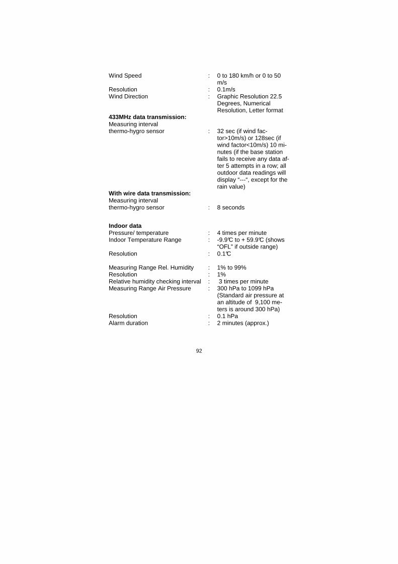
Wind Speed : 0 to 180 km/h or 0 to 50 m/s
Resolution : 0.1m/s Wind Direction : Graphic Resolution 22.5
Degrees, Numerical Resolution, Letter format 433MHz data transmission: Measuring interval thermo-hygro sensor : 32 sec (if wind fac-
tor>10m/s) or 128sec (if wind factor<10m/s) 10 mi-nutes (if the base station fails to receive any data af-ter 5 attempts in a row; all outdoor data readings will display “---“, except for the rain value)
With wire data transmission: Measuring interval thermo-hygro sensor : 8 seconds
Indoor data Pressure/ temperature : 4 times per minute Indoor Temperature Range : -9.9°C to + 59.9°C (shows
“OFL” if outside range) Resolution : 0.1°C Measuring Range Rel. Humidity : 1% to 99% Resolution : 1% Relative humidity checking interval : 3 times per minute Measuring Range Air Pressure : 300 hPa to 1099 hPa
(Standard air pressure at an altitude of 9,100 me-ters is around 300 hPa)
Resolution : 0.1 hPa Alarm duration : 2 minutes (approx.)
93
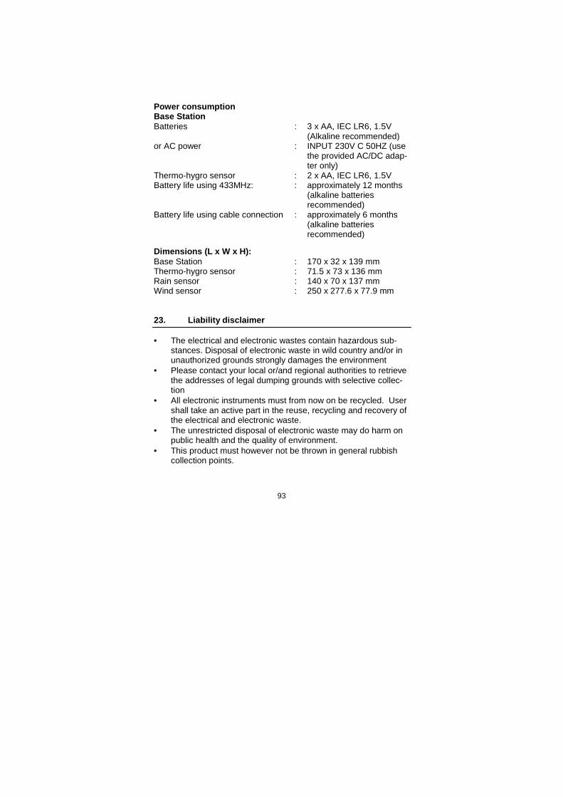
Power consumption Base Station Batteries : 3 x AA, IEC LR6, 1.5V
(Alkaline recommended) or AC power : INPUT 230V C 50HZ (use
the provided AC/DC adap-ter only)
Thermo-hygro sensor : 2 x AA, IEC LR6, 1.5V Battery life using 433MHz: : approximately 12 months (alkaline batteries recommended) Battery life using cable connection : approximately 6 months (alkaline batteries recommended) Dimensions (L x W x H): Base Station : 170 x 32 x 139 mm Thermo-hygro sensor : 71.5 x 73 x 136 mm Rain sensor : 140 x 70 x 137 mm Wind sensor : 250 x 277.6 x 77.9 mm 23. Liability disclaimer • The electrical and electronic wastes contain hazardous sub-
stances. Disposal of electronic waste in wild country and/or in unauthorized grounds strongly damages the environment
• Please contact your local or/and regional authorities to retrieve the addresses of legal dumping grounds with selective collec-tion
• All electronic instruments must from now on be recycled. User shall take an active part in the reuse, recycling and recovery of the electrical and electronic waste.
• The unrestricted disposal of electronic waste may do harm on public health and the quality of environment.
• This product must however not be thrown in general rubbish collection points.
94
• As stated on the gift box and labeled on the product, reading the “User manual” is highly recommended for the benefit of the user.
• The manufacturer and supplier cannot accept any responsibili-ty for any incorrect readings and any consequences that occur should an inaccurate reading take place.
• This product is not to be used for medical purposes or for pub-lic information.
• This product is only designed to be used in the home as indica-tion of the future weather and is not 100% accurate. Weather forecasts given by this product should be taken only as an in-dication and not as being totally accurate.
• The specifications of this product may change without prior notice.
• This product is not a toy. Keep out of the reach of children. • No part of this manual may be reproduced without written con-
sent of the manufacturer.
R&TTE Directive 1999/5/EC Summary of the Declaration of Conformity : We hereby declare that this wireless transmission device does comply with the essential requirements of R&TTE Directive 1999/5/EC.