Embed Size (px)
Citation preview
World Leader in Production TechnologyWorld Leader in Production TechnologyWorld Leader in Production TechnologyWorld Leader in Production Technology
OPERATION MANUALOPERATION MANUALOPERATION MANUALOPERATION MANUAL
580 SERIES CONTROLLER
TEACH PENDANT
HD-3810E-1

World Leader in Production TechnologyWorld Leader in Production TechnologyWorld Leader in Production TechnologyWorld Leader in Production Technology

The information contained herein is the property of Hirata Corporation and shall not bereproduced in whole or in part without prior written approval of Hirata Corporation. Theinformation contained herein is subject to change without notice and should not beconstructed as a commitment by Hirata Corporation.
Hirata Corporation assumes no responsibility for any errors or omissions in this document.
Warranty
All of Hirata's products which is passed our formal inspection test shall be guaranteed againstfaults due to the negligence of Hirata for either earlier period of one year or four thousandhours of operation from the day of shipment from Hirata Factory.
This warranty shall be applicable to the parts replacement and/or labor for repair in our factoryand transportation cost shall not be applied.
We will charge the repair of faults caused by the following reasons:
* Wrong usage which are prohibited in the instruction manual.* After the expiration of guarantee period.* Earthquake, fire, riot, violence, war and other force majeure.* Modification, repair or adjustment is performed by unauthorized person.
Contact your sales agent for individual warranty coverage.
580 Series Controller Teach PendantOperation Manual (HD-3810E-1)
Copyright 1998 by Hirata Corporation All right reserved.First published in October 1998First revision in June 1999Printed in JapanHirata Corporation
Tokyo Head Quarters3-9-20 Togoshi, Shinagawa, Tokyo 142-0041 JAPANPhone (03) 3786-1226Facsimile (03) 3786-1264
Robotics Division1016-6 Kusuno, Kumamoto 861-5511 JAPANPhone (096) 245-1333Facsimile (096) 245-0816
NOTATIONS
i
NotationsNotationsNotationsNotations
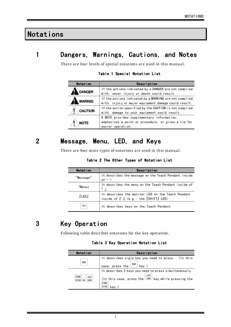
1111 Dangers, Dangers, Dangers, Dangers, WarningsWarningsWarningsWarnings,,,, Cautions, and Notes Cautions, and Notes Cautions, and Notes Cautions, and NotesThere are four levels of special notations are used in this manual.
Table Table Table Table 1111 Special Notation ListSpecial Notation ListSpecial Notation ListSpecial Notation List
NotationNotationNotationNotation DescriptionDescriptionDescriptionDescription
!!!! DANGERDANGERDANGERDANGERIf the actions indicated by a DANGER are not complied
with, sever injury or death could result.
!!!! WARINIGWARINIGWARINIGWARINIGIf the actions indicated by a WARNING are not complied
with, injury or major equipment damage could result.
!!!! CAUTIONCAUTIONCAUTIONCAUTIONIf the action specified by the CAUTION is not complied
with, damage to your equipment could result.
!!!! NOTENOTENOTENOTE
A NOTE provides supplementary information,
emphasizes a point or procedure, or gives a tip for
easier operation.
2222 Message, Menu, LED, and KeysMessage, Menu, LED, and KeysMessage, Menu, LED, and KeysMessage, Menu, LED, and KeysThere are four more types of notations are used in this manual.
Table Table Table Table 2222 The Other Types of Notation List The Other Types of Notation List The Other Types of Notation List The Other Types of Notation List
NotationNotationNotationNotation DescriptionDescriptionDescriptionDescription
“Message”It describes the message on the Teach Pendant inside
of “ “.
「Menu」It describes the menu on the Teach Pendant inside of
「 」.
『LED』It describes the monitor LED on the Teach Pendant
inside of 『 』 (e.g., the 『SHIFT』 LED)
END It describes keys on the Teach Pendant.
3333 Key OperationKey OperationKey OperationKey OperationFollowing table describes notations for the key operation.
Table Table Table Table 3333 Key Operation Notation List Key Operation Notation List Key Operation Notation List Key Operation Notation List
NotationNotationNotationNotation DescriptionDescriptionDescriptionDescription
END
It describes sigle key you need to press. (In this
case, press the END
key )
FUNC
HIGH+spd
CAN
It describes 2 keys you need to press simultaneously.
(In this case, press the spd
CAN key while pressing theFUNC
HIGH key.)
CHAPTER 1 ABOUT THIS MANUAL AND NOTICE
1-1
CHAPTER 1CHAPTER 1CHAPTER 1CHAPTER 1 About This Manual and About This Manual and About This Manual and About This Manual and NoticeNoticeNoticeNotice
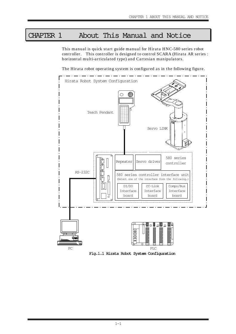
This manual is quick start guide manual for Hirata HNC-580 series robotcontroller. This controller is designed to control SCARA (Hirata AR series :horizontal multi-articulated type) and Cartesian manipulators.
The Hirata robot operating system is configured as in the following figure.
PLC
Teach Pendant
Servo LINK
580 series
controller
RS-232C
Compo/Bus
Interface
board
CC-Link
Interface
board
DI/DO
Interface
board
580 series controller interface unit(Select one of the interface form the following.)
Hirata Robot System Configuration
Servo driver
PC
HN
C
Repeater
Fig.1.Fig.1.Fig.1.Fig.1.1111 Hirata Robot System Configuration Hirata Robot System Configuration Hirata Robot System Configuration Hirata Robot System Configuration
CHAPTER 1 ABOUT THIS MANUAL AND NOTICE
1-2
The basic outline for setting up the robot system is described in this chapter.It may differs depending on robot and controller type.
(1) External cables
Power cable, servo LINK cable, Motor line, etc.
(2) E.S. release
• Check if the Deadman switch is not pressed in TEACH orCHECK mode when the power is ON.
• Check if the E.S. switch on the Teach Pendant is pressed whenthe power is ON.
• Check if the E.S. connectors on the controller are opened.
• Check if the DC24 fuse is blown.
Refer to separate volume, “Robot Controller Users Guide,Emergency Stop (E.S.) Functions” for details.
(3) A-CAL
Refer to Chapter 3, “A-CAL (Automatic Calibration)” for details.
(4) Teaching
Before the robot starts automatic operation, it is required to pre-teach the operating positions.
The Hirata robot operating system can accept following methods toteach the robot position.
• Enter the coordinate manually via key pad on the TeachPendant.
• MDI (Manual Data Input). Move the robot physically andstore the position (hereinafter referred to as “Teaching”).
• Off-line teaching. Data transfer via memory card or RS-232C.
• Data transfer via HR editor i.
After teaching positions to the robot, check to see that the robotmoves to the taught position correctly. Then, automatic operationis performed by transmitting signals with external devices.
Using the Teach Pendant, the robot data, which called “systemdata”, can be entered. Input and output operations can beperformed.
Refer to Chapter 5, “TEACH Mode” for details.
i: Refer to separated volume, “HR Editor Operation Manual.”
CHAPTER 1 ABOUT THIS MANUAL AND NOTICE
1-3
(5) Check
• Set the conditions of robot operations using System Parameters.Speed, Acceleration/Deceleration, “PULL-UP” motion, “ARCHUP/DOWN” motion, etc.Refer to Chapter 19, “Details of System Parameters” for details.
• Check the entered position data in CHECK mode.Refer to Chapter 6, “CHECK Mode” for details.
(6) Automatic operation
Check the robot operations after checking the following items.Refer to later chapter 7, “ON-LINE Mode” for details.
• AUTO ModeI/O signal check
• ON-LINE ModeData transmission speed with host PC.Station ID number for each robot.
There are some differences in operating procedures depending upon therobot model or system configuration. Ask your system integrator fordetailed specification. Hirata also offers robot control language HARL-U1and HARL-III as add-ons to the standard operating system. Contact yourdistributor for details.
・ Verify all the cable connectors are properly and firmly connected.・ Confirm there is no operator or any obstacles in robot’s working envelope.・ Unspecified usage of this robot may result severe injury or death. Do
not install the robot in any other manner than the ones specified in thismanual.
・ Do not throw or drop the Teach Pendant.・ Do not use the entire system at higher than 40℃ and high humidity.
The surroundings must be no dust, no smoke, no combustion, and nocorrosion.
・ Do not stress the Teach Pendant cable connection. Hold the Pendantbody when carrying.
・ When servicing or teaching, no one should put the system into operation.It is suggested to prepare a sign stating not to activate the system.
CHAPTER 2 CONNECTING THE TEACH PENDANT
2-1
CHAPTER 2CHAPTER 2CHAPTER 2CHAPTER 2 Connecting the Teach PendantConnecting the Teach PendantConnecting the Teach PendantConnecting the Teach Pendant
2.12.12.12.1 Naming andNaming andNaming andNaming and F F F Functionunctionunctionunction ofofofof the the the the TTTTeacheacheacheach P P P Pendantendantendantendant
2.1.12.1.12.1.12.1.1 Appearance of the Teach PendantAppearance of the Teach PendantAppearance of the Teach PendantAppearance of the Teach Pendant
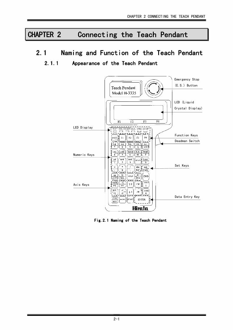
Fig.2.Fig.2.Fig.2.Fig.2.1111 NNNNamingamingamingaming of the Teach Pendant of the Teach Pendant of the Teach Pendant of the Teach Pendant
Emergency Stop
(E.S.) Button
LCD (Liquid
Crystal Display)
LED Display
Numeric Keys
Axis Keys
Function Keys
Deadman Switch
Set Keys
Data Entry Key
CHAPTER 2 CONNECTING THE TEACH PENDANT
2-2
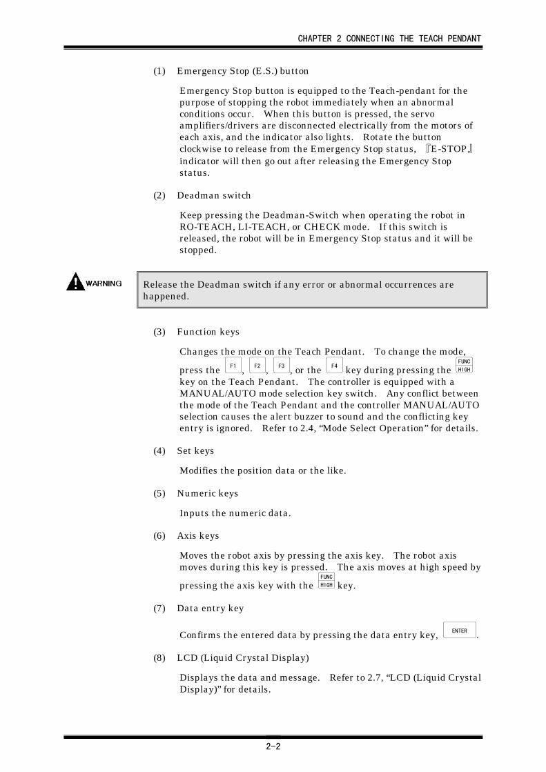
(1) Emergency Stop (E.S.) button
Emergency Stop button is equipped to the Teach-pendant for thepurpose of stopping the robot immediately when an abnormalconditions occur. When this button is pressed, the servoamplifiers/drivers are disconnected electrically from the motors ofeach axis, and the indicator also lights. Rotate the buttonclockwise to release from the Emergency Stop status, 『E-STOP』indicator will then go out after releasing the Emergency Stopstatus.
(2) Deadman switch
Keep pressing the Deadman-Switch when operating the robot inRO-TEACH, LI-TEACH, or CHECK mode. If this switch isreleased, the robot will be in Emergency Stop status and it will bestopped.
Release the Deadman switch if any error or abnormal occurrences arehappened.
(3) Function keys
Changes the mode on the Teach Pendant. To change the mode,
press the F1 , F2 , F3 , or the F4 key during pressing the FUNC
HIGH
key on the Teach Pendant. The controller is equipped with aMANUAL/AUTO mode selection key switch. Any conflict betweenthe mode of the Teach Pendant and the controller MANUAL/AUTOselection causes the alert buzzer to sound and the conflicting keyentry is ignored. Refer to 2.4, “Mode Select Operation” for details.
(4) Set keys
Modifies the position data or the like.
(5) Numeric keys
Inputs the numeric data.
(6) Axis keys
Moves the robot axis by pressing the axis key. The robot axismoves during this key is pressed. The axis moves at high speed by
pressing the axis key with the FUNC
HIGH key.
(7) Data entry key
Confirms the entered data by pressing the data entry key, ENTER .
(8) LCD (Liquid Crystal Display)
Displays the data and message. Refer to 2.7, “LCD (Liquid CrystalDisplay)” for details.
CHAPTER 2 CONNECTING THE TEACH PENDANT
2-3
(9) LED display
① 『SHIFT』
Every time the SHIFT
key is pressed, the 『SHIFT』 LED willswitch between ON and OFF. When the 『SHIFT』 LED is lit,the functions of the lower case letters on the pink are selected.
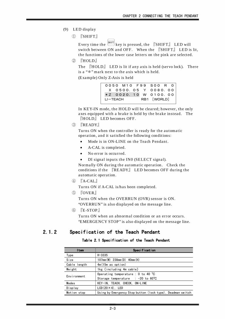
② 『HOLD』The 『HOLD』 LED is lit if any axis is held (servo lock). Thereis a “*” mark next to the axis which is held.(Example) Only Z-Axis is held
0050 M10 F99 S00 R 0
X 0500.05 Y 0080.00
*Z 0020.10 W 0100.00
LI-TEACH RB1 [WORLD]
In KEY-IN mode, the HOLD will be cleared; however, the onlyaxes equipped with a brake is held by the brake instead. The『HOLD』 LED becomes OFF.
③ 『READY』Turns ON when the controller is ready for the automaticoperation, and it satisfied the following conditions:• Mode is in ON-LINE on the Teach Pendant.• A-CAL is completed.• No error is occurred.• DI signal inputs the IN0 (SELECT signal).
Normally ON during the automatic operation. Check theconditions if the 『READY』 LED becomes OFF during theautomatic operation.
④ 『A-CAL』Turns ON if A-CAL is/has been completed.
⑤ 『OVER』Turns ON when the OVERRUN (OVR) sensor is ON.“OVERRUN” is also displayed on the message line.
⑥ 『E-STOP』Turns ON when an abnormal condition or an error occurs.“EMERGENCY STOP” is also displayed on the message line.
2.1.22.1.22.1.22.1.2 Specification of the Teach PendantSpecification of the Teach PendantSpecification of the Teach PendantSpecification of the Teach Pendant
Table 2.Table 2.Table 2.Table 2.1111 Specification of the Teach PendantSpecification of the Teach PendantSpecification of the Teach PendantSpecification of the Teach Pendant
ItemItemItemItem SpecificationSpecificationSpecificationSpecification
Type H-3335
Size 107mm(W) 238mm(D) 40mm(H)
Cable length 4m(15m as option)
Weight 1kg(including 4m cable)
EnvironmentOperating temperature : 0 to 40 ℃
Storage temperature : -20 to 60℃
Modes KEY-IN, TEACH, CHECK, ON-LINE
Display LCD(20×4), LED
Motion stop Using by Emergency Stop button (lock type), Deadman switch
CHAPTER 2 CONNECTING THE TEACH PENDANT
2-4
2.22.22.22.2 Connecting the Teach Pendant to theConnecting the Teach Pendant to theConnecting the Teach Pendant to theConnecting the Teach Pendant to the
ControllerControllerControllerControllerBefore using the robot, you need to go through following procedure. Thischapter describes the step by step procedures to be used before starting thesystem:
Physically connecting the Teach Pendant to the controller
Configuring the Teach Pendant to the controller.
2.2.12.2.12.2.12.2.1 Physically Connecting the Teach Pendant to thePhysically Connecting the Teach Pendant to thePhysically Connecting the Teach Pendant to thePhysically Connecting the Teach Pendant to the
ControllerControllerControllerController
(1) Press the Remove switch i on the controller or the repeater, andconnect the Teach Pendant connector. This switch has to bepressed until the connection is completed.
Make sure to keep pressing the Remove switch whileconnecting/disconnecting the Teach Pendant. This switch is directlyconnected to the power source circuit and will shut off the power if theswitch is released during this operation. If the system shuts down, it isnecessary to reboot the system. The sudden power shut down during robotoperation may result in hardware damage. You can connect/disconnect theTeach Pendant while the power is ON; however, it is suggested toconnect/disconnect the Teach Pendant after the power is OFF unlessnecessary. A dummy connector should be installed when the system runswithout the Teach Pendant.
(2) Remove the Dummy Connector. You need to release the lock boltson the Dummy connector before removing. (When youdisconnecting the Teach Pendant, release the lock bolts on the TeachPendant connector same as the Dummy connector removal.
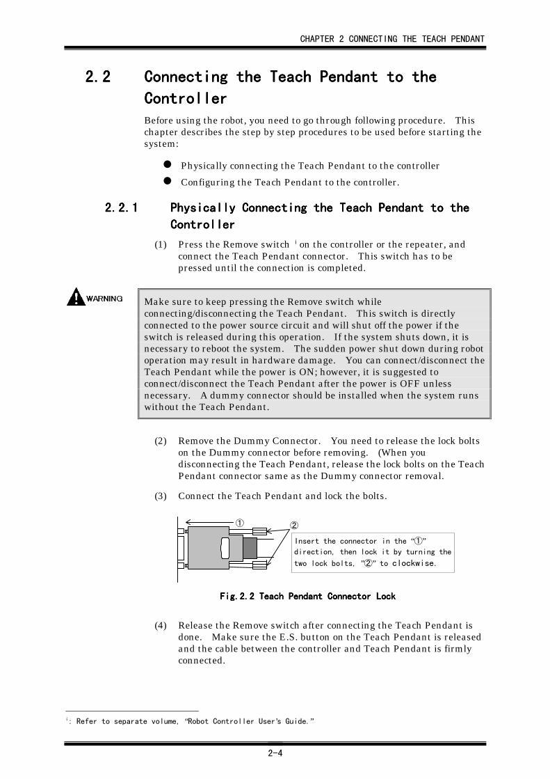
(3) Connect the Teach Pendant and lock the bolts.
Fig.2.Fig.2.Fig.2.Fig.2.2222 Teach Pendant Connector LockTeach Pendant Connector LockTeach Pendant Connector LockTeach Pendant Connector Lock
(4) Release the Remove switch after connecting the Teach Pendant isdone. Make sure the E.S. button on the Teach Pendant is releasedand the cable between the controller and Teach Pendant is firmlyconnected.
i: Refer to separate volume, “Robot Controller User’s Guide.”
Insert the connector in the “①”direction, then lock it by turning the
two lock bolts, ”②” to clockwise.
① ②
CHAPTER 2 CONNECTING THE TEACH PENDANT
2-5
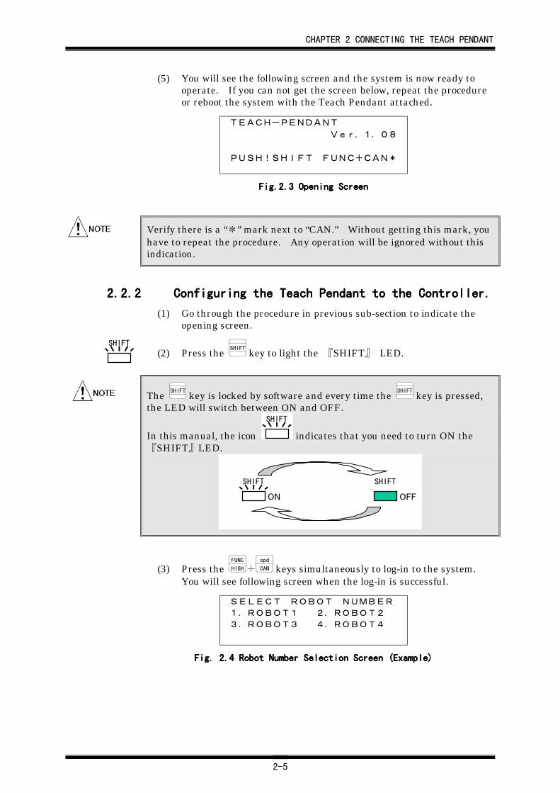
(5) You will see the following screen and the system is now ready tooperate. If you can not get the screen below, repeat the procedureor reboot the system with the Teach Pendant attached.
TEACH-PENDANT
Ver.1.08
PUSH!SHIFT FUNC+CAN*
Fig.2.Fig.2.Fig.2.Fig.2.3333 Opening Screen Opening Screen Opening Screen Opening Screen
Verify there is a “*” mark next to “CAN.” Without getting this mark, youhave to repeat the procedure. Any operation will be ignored without thisindication.
2.2.22.2.22.2.22.2.2 Configuring the Teach Pendant to the Controller.Configuring the Teach Pendant to the Controller.Configuring the Teach Pendant to the Controller.Configuring the Teach Pendant to the Controller.
(1) Go through the procedure in previous sub-section to indicate theopening screen.
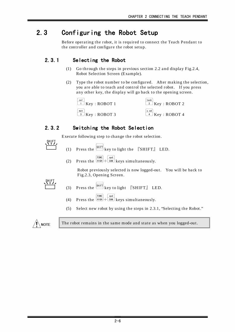
(2) Press the SHIFT
key to light the 『SHIFT』 LED.
The SHIFT
key is locked by software and every time the SHIFT
key is pressed,the LED will switch between ON and OFF.
In this manual, the icon
SHIFT
indicates that you need to turn ON the『SHIFT』LED.
SHIFT SHIFT
ON OFF
(3) Press the FUNC
HIGH+spd
CAN keys simultaneously to log-in to the system.You will see following screen when the log-in is successful.
SELECT ROBOT NUMBER
1.ROBOT1 2.ROBOT2
3.ROBOT3 4.ROBOT4
Fig. 2.Fig. 2.Fig. 2.Fig. 2.4444 Robot Number Selection Screen (Example) Robot Number Selection Screen (Example) Robot Number Selection Screen (Example) Robot Number Selection Screen (Example)
SHIFT
CHAPTER 2 CONNECTING THE TEACH PENDANT
2-6
2.32.32.32.3 Configuring the Robot SetupConfiguring the Robot SetupConfiguring the Robot SetupConfiguring the Robot SetupBefore operating the robot, it is required to connect the Teach Pendant tothe controller and configure the robot setup.
2.3.12.3.12.3.12.3.1 Selecting the RobotSelecting the RobotSelecting the RobotSelecting the Robot
(1) Go through the steps in previous section 2.2 and display Fig.2.4,Robot Selection Screen (Example).
(2) Type the robot number to be configured. After making the selection,you are able to teach and control the selected robot. If you pressany other key, the display will go back to the opening screen.
cal
1 Key:ROBOT 1task
2 Key:ROBOT 2
mot
3 Key:ROBOT 3s.ed
4 Key:ROBOT 4
2.3.22.3.22.3.22.3.2 Switching the Robot SelectionSwitching the Robot SelectionSwitching the Robot SelectionSwitching the Robot Selection
Execute following step to change the robot selection.
(1) Press the SHIFT
key to light the 『SHIFT』 LED.
(2) Press the FUNC
HIGH+spd
CAN keys simultaneously.
Robot previously selected is now logged-out. You will be back toFig.2.3, Opening Screen.
(3) Press the SHIFT
key to light 『SHIFT』 LED.
(4) Press the FUNC
HIGH+spd
CAN keys simultaneously.
(5) Select new robot by using the steps in 2.3.1, “Selecting the Robot.”
The robot remains in the same mode and state as when you logged-out.
SHIFT
SHIFT
CHAPTER 2 CONNECTING THE TEACH PENDANT
2-7
2.42.42.42.4 ModeModeModeMode Select Operation Select Operation Select Operation Select OperationHirata system is provided with 4 modes. This section describes eachfunction and mode selection tips.
Table 2.Table 2.Table 2.Table 2.2222 Mode FunctionMode FunctionMode FunctionMode Function
ModeModeModeMode FunctionFunctionFunctionFunction
KEY-INEntering the data using the numeric key and
handling the memory card data.
TEACH Manipulates the robot to teach positions
CHECKChecking the stored robot positions by physically
moving the robot
ON-LINEAccepts PLC or PC commands to drive
automatically.
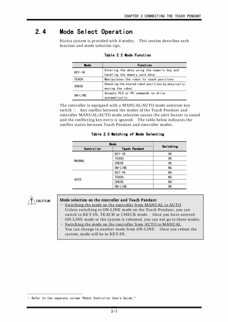
The controller is equipped with a MANUAL/AUTO mode selection keyswitch i. Any conflict between the modes of the Teach Pendant andcontroller MANUAL/AUTO mode selection causes the alert buzzer to soundand the conflicting key entry is ignored. The table below indicates theconflict status between Teach Pendant and controller modes.
Table 2.Table 2.Table 2.Table 2.3333 Matching of Mode Matching of Mode Matching of Mode Matching of Mode SSSSelectingelectingelectingelecting
ModeModeModeMode
ControllerControllerControllerController Teach PendantTeach PendantTeach PendantTeach PendantSwitchingSwitchingSwitchingSwitching
KEY-IN OK
TEACH OK
CHECK OKMAUNAL
ON-LINE NG
KEY-IN NG
TEACH NG
CHECK NGAUTO
ON-LINE OK
Mode selection on the controller and Teach PendantMode selection on the controller and Teach PendantMode selection on the controller and Teach PendantMode selection on the controller and Teach Pendant・ Switching the mode on the controller from MANUAL to AUTO
Unless switching to ON-LINE mode on the Teach Pendant, you canswitch to KEY-IN, TEACH or CHECK mode. Once you have enteredON-LINE mode or the system is rebooted, you can not go to these modes.
・ Switching the mode on the controller from AUTO to MANUALYou can change to another mode from ON-LINE. Once you reboot thesystem, mode will be in KEY-IN.
i: Refer to the separate volume “Robot Controller User’s Guide.”
CHAPTER 2 CONNECTING THE TEACH PENDANT
2-8
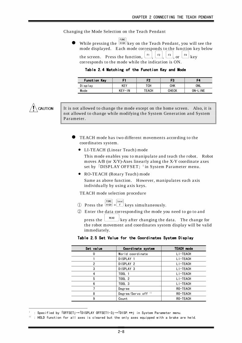
Changing the Mode Selection on the Teach Pendant
While pressing the FUNC
HIGH key on the Teach Pendant, you will see themode displayed. Each mode corresponds to the function key below
the screen. Press the function, F1 , F2 , F3 , or F4 keycorresponds to the mode while the indication is ON.
Table 2.Table 2.Table 2.Table 2.4444 Matching of the Function Key and Matching of the Function Key and Matching of the Function Key and Matching of the Function Key and MMMModeodeodeode
Function KeyFunction KeyFunction KeyFunction Key F1F1F1F1 F2F2F2F2 F3F3F3F3 F4F4F4F4
Display KEY TCH CHK ONL
Mode KEY-IN TEACH CHECK ON-LINE
It is not allowed to change the mode except on the home screen. Also, it isnot allowed to change while modifying the System Generation and SystemParameter.
TEACH mode has two different movements according to thecoordinates system.
• LI-TEACH (Linear Teach) modeThis mode enables you to manipulate and teach the robot. Robotmoves A/B (or X/Y)-Axes linearly along the X-Y coordinate axesset by 「DISPLAY OFFSET」 i in System Parameter menu.
• RO-TEACH (Rotary Teach) modeSame as above function. However, manipulates each axisindividually by using axis keys.
TEACH mode selection procedure
① Press the FUNC
HIGH +local
F keys simultaneously.
② Enter the data corresponding the mode you need to go to and
press the READ key after changing the data. The change forthe robot movement and coordinates system display will be validimmediately.
Table 2.Table 2.Table 2.Table 2.5555 Set Value for Set Value for Set Value for Set Value for thethethethe Coordinates System Display Coordinates System Display Coordinates System Display Coordinates System Display
Set valueSet valueSet valueSet value Coordinate systemCoordinate systemCoordinate systemCoordinate system TEACH modeTEACH modeTEACH modeTEACH mode
0 World coordinate LI-TEACH
1 DISPLAY 1 LI-TEACH
2 DISPLAY 2 LI-TEACH
3 DISPLAY 3 LI-TEACH
4 TOOL 1 LI-TEACH
5 TOOL 2 LI-TEACH
6 TOOL 3 LI-TEACH
7 Degree RO-TEACH
8 Degree/Servo off ii RO-TEACH
9 Count RO-TEACH
i : Specified by 「OFFSET」→「DISPLAY OFFSET1-3」→「DISP.**」 in System Parameter menu.ii : HOLD function for all axes is cleared but the only axes equipped with a brake are held.
CHAPTER 2 CONNECTING THE TEACH PENDANT
2-9
2.52.52.52.5 Emergency Stop Emergency Stop Emergency Stop Emergency Stop (E.S.) (E.S.) (E.S.) (E.S.) ButtonuttonuttonuttonTo stop the robot immediately when an abnormal condition occurs, theTeach Pendant is equipped with an Emergency Stop (E.S.) button. Whenthis button is pressed, the power supply to the servo unit (servo driver andthe motor for each axis) is cut off. The『E-STOP』indicator also lights.Rotate the button clockwise to release from the emergency stop status.The indicator will then go out after releasing the emergency stop status.
2.62.62.62.6 Basic Entry ProcedureBasic Entry ProcedureBasic Entry ProcedureBasic Entry ProcedureThis section describes the basic key entry procedure.
(1) Selecting the entry item
The data entry item can be selected by moving the cursor. Press
the up
DOWN key to choose the item to edit and enter the data. This keyis the only key to move the cursor if there are no specific proceduresdescribed.
(2) Numeric data
The numeric keys: +
- , *
0 , /
. , cal
1 , task
2 , mot
3 , s.ed
4 , p.ed
5 , home
6 ,s.g
7 , s.p
8 , and key
9 are used for data entry of the coordinates andthe system data. When pressing the numeric keys, the numbercorresponding to the keys will be displayed on the Teach Pendant.
However the +
- and /
. keys entry may be ignored when thedata form is invalid.
Example for data entry;
① Input the data.
② Press the ENTER key. “ENTER OK ?” is displayed on the
message line. Press the ENTER key again to confirm the data,or press any other key to cancel the data.
③ The data input by numeric keys in step ① is automaticallyformatted in the following manner. If you enter the data for thecoordinate (rectangular coordinate), the data is displayed asfollows:• +123456.789 → 4569.00 (Invalid data entry)
• +456.7 → 0456.70
• -12 → -0012.00When the figure of the input data exceeds the allowable digits,the data will be displayed differently such as in first example.Also, if positive data is entered with a “+”, the “+” will not bedisplayed on the screen. It is not necessary to enter the “+”when you enter the positive data.
E-STOP E-STOP
CHAPTER 2 CONNECTING THE TEACH PENDANT
2-10
(3) ON/OFF entry
The data displayed, “ON” or “OFF”, is the switch data. You can
select “ON” or “OFF” using the io
SEL key or the numeric keys, *
0 orcal
1 . Using the io
SEL key, “ON” and “OFF” are switched between
alternately. The *
0 key corresponds to “OFF,” and the cal
1 key
to “ON.” Press the ENTER key twice to confirm the entered data.
(4) YES/NO entry
The data displayed, “YES” or “NO,” is the switch data. You can
select “YES” or “NO” using the io
SEL key or the numeric keys, *
0 orcal
1 . Using the io
SEL key, “YES” and “NO” is switched between
alternately. The *
0 key corresponds to “NO,” and the cal
1 key to
“YES.” Press the ENTER key twice to confirm the entered data.
(5) Character selection entry
When selecting a text item from a list, (e.g., 「TRANSFER RATE」 i
in System Generation menu or mode select in the position memory
operation mode) the data can be selected with the io
SEL key or the
numeric keys, *
0 to key
9 . The io
SEL key is used when indexingthrough the list in order. For example, the data or 「TRANSFERRATE」 can be selected in the following order:
300→600→1200→2400→4800→9600→19200→38400
The numeric keys correspond as below;
0: 300/1: 600/・・・/5: 9600/6: 192000
When using numeric keys, a maximum of ten items, *
0 to key
9 ,can be selected.
Press the ENTER key twice to confirm the entered data.
i: Specified by 「ORIGIN」→「SET-UP SYSTEM」→「TRANSFER RATE」 in System Generation menu.
CHAPTER 2 CONNECTING THE TEACH PENDANT
2-11
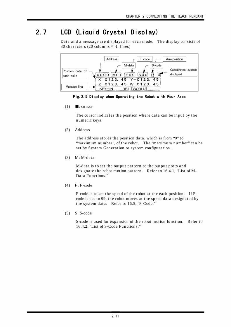
2.72.72.72.7 LCD (Liquid Crystal Display)LCD (Liquid Crystal Display)LCD (Liquid Crystal Display)LCD (Liquid Crystal Display)Data and a message are displayed for each mode. The display consists of80 characters (20 columns×4 lines)
0000 M01 F99 S00 R 0
X 0123.45 Y-0123.45
Z 0123.45 W 0123.45
KEY-IN RB1 [WORLD]
Address F-code
M-data
Arm position
Coordinates system
displayed
S-code
Position data of
each axis
Message line
Fig.2.Fig.2.Fig.2.Fig.2.5555 Display when Operating the Robot with Four Axes Display when Operating the Robot with Four Axes Display when Operating the Robot with Four Axes Display when Operating the Robot with Four Axes
(1) ■: cursor
The cursor indicates the position where data can be input by thenumeric keys.
(2) Address
The address stores the position data, which is from “0” to“maximum number”, of the robot. The “maximum number” can beset by System Generation or system configuration.
(3) M: M-data
M-data is to set the output pattern to the output ports anddesignate the robot motion pattern. Refer to 16.4.1, “List of M-Data Functions.”
(4) F: F-code
F-code is to set the speed of the robot at the each position. If F-code is set to 99, the robot moves at the speed data designated bythe system data. Refer to 16.5, “F-Code.”
(5) S: S-code
S-code is used for expansion of the robot motion function. Refer to16.4.2, “List of S-Code Functions.”
CHAPTER 2 CONNECTING THE TEACH PENDANT
2-12
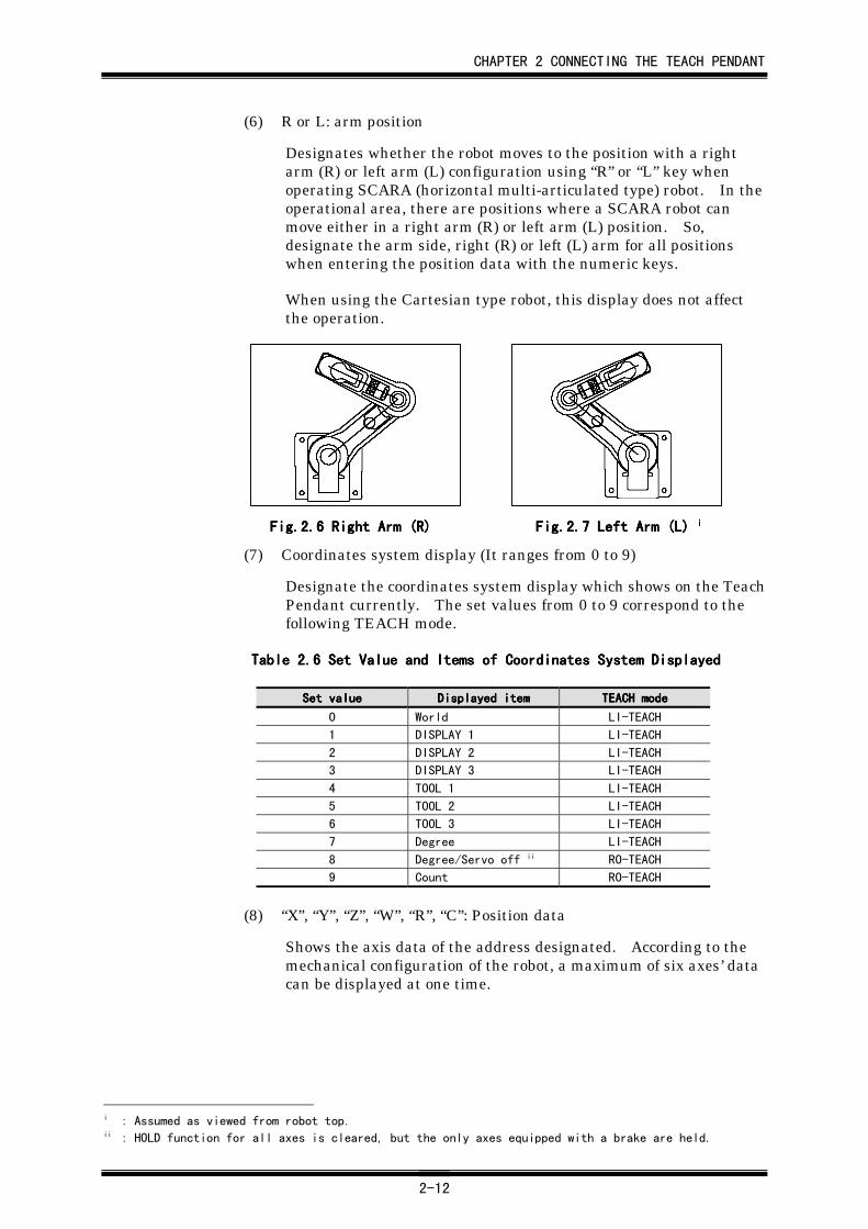
(6) R or L: arm position
Designates whether the robot moves to the position with a rightarm (R) or left arm (L) configuration using “R” or “L” key whenoperating SCARA (horizontal multi-articulated type) robot. In theoperational area, there are positions where a SCARA robot canmove either in a right arm (R) or left arm (L) position. So,designate the arm side, right (R) or left (L) arm for all positionswhen entering the position data with the numeric keys.
When using the Cartesian type robot, this display does not affectthe operation.
Fig.2.Fig.2.Fig.2.Fig.2.6666 Right Arm Right Arm Right Arm Right Arm (R(R(R(R)))) Fig.2.Fig.2.Fig.2.Fig.2.7777 Left Arm (L) Left Arm (L) Left Arm (L) Left Arm (L) iiii
(7) Coordinates system display (It ranges from 0 to 9)
Designate the coordinates system display which shows on the TeachPendant currently. The set values from 0 to 9 correspond to thefollowing TEACH mode.
Table 2.Table 2.Table 2.Table 2.6666 Set Value and Items of Coordinates System Displayed Set Value and Items of Coordinates System Displayed Set Value and Items of Coordinates System Displayed Set Value and Items of Coordinates System Displayed
Set valueSet valueSet valueSet value Displayed itemDisplayed itemDisplayed itemDisplayed item TEACH modeTEACH modeTEACH modeTEACH mode
0 World LI-TEACH
1 DISPLAY 1 LI-TEACH
2 DISPLAY 2 LI-TEACH
3 DISPLAY 3 LI-TEACH
4 TOOL 1 LI-TEACH
5 TOOL 2 LI-TEACH
6 TOOL 3 LI-TEACH
7 Degree LI-TEACH
8 Degree/Servo off ii RO-TEACH
9 Count RO-TEACH
(8) “X”, “Y”, “Z”, “W”, “R”, “C”: Position data
Shows the axis data of the address designated. According to themechanical configuration of the robot, a maximum of six axes’ datacan be displayed at one time.
i : Assumed as viewed from robot top.ii : HOLD function for all axes is cleared, but the only axes equipped with a brake are held.
CHAPTER 2 CONNECTING THE TEACH PENDANT
2-13
(9) Message line
Displays the message, general and error messages. Refer toChapter 23, “Message” for details.
While pressing the READ key in any mode except KEY-IN mode, the
display shows the software version built-in the controller. Forexample, “OLD DATA V5.xx” means the software version 5.xx isused in the controller.
(10) Function
While pressing the FUNC
HIGH and the cal
1 to key
9 , io
SEL , m.c
M.OUT , k.in
M , k.out
S ,local
F , or seq
A keys, the function mode is selected. It designates themode which is currently displayed on the Teach Pendant. Refer to2.9, “Function Mode” for details.
2.82.82.82.8 Special KeysSpecial KeysSpecial KeysSpecial Keys
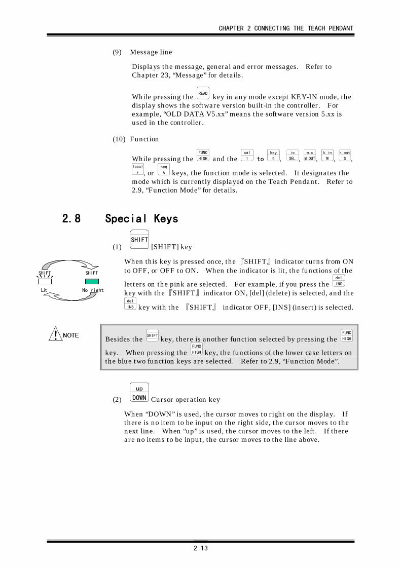
(1) SHIFT
[SHIFT] key
When this key is pressed once, the 『SHIFT』 indicator turns from ONto OFF, or OFF to ON. When the indicator is lit, the functions of the
letters on the pink are selected. For example, if you press the del
INS
key with the 『SHIFT』 indicator ON, [del] (delete) is selected, and thedel
INS key with the 『SHIFT』 indicator OFF, [INS] (insert) is selected.
Besides the SHIFT
key, there is another function selected by pressing the FUNC
HIGH
key. When pressing the FUNC
HIGH key, the functions of the lower case letters onthe blue two function keys are selected. Refer to 2.9, “Function Mode”.
(2) up
DOWN Cursor operation key
When “DOWN” is used, the cursor moves to right on the display. Ifthere is no item to be input on the right side, the cursor moves to thenext line. When “up” is used, the cursor moves to the left. If thereare no items to be input, the cursor moves to the line above.
SHIFT SHIFT
Lit No right
CHAPTER 2 CONNECTING THE TEACH PENDANT
2-14
2.92.92.92.9 Function ModeFunction ModeFunction ModeFunction Mode
The mode selected by the FUNC
HIGH with blue colored key, such as the cal
1 to key
9 ,io
SEL , k.in
M , seq
A , k.out
S , local
F , and m.c
M.OUT keys, is the function mode. This modecan be activated in any other mode. However, in order to display it, thedisplay stage on the Teach Pendant must be in the home stage described initem (2) below.
In ON-LINE mode, the data is displayed but no data cannot be input.
(1) FUNC
HIGH +cal
1 [cal] keys (calculation)
Calculates the robot individual characteristic values and the offsetvalue or creates position data (palletizing software). Refer toChapter 12 , “Automatic Creation of Position Data & Parameters”for details.
(2) FUNC
HIGH +task
2 [task] keys (task)
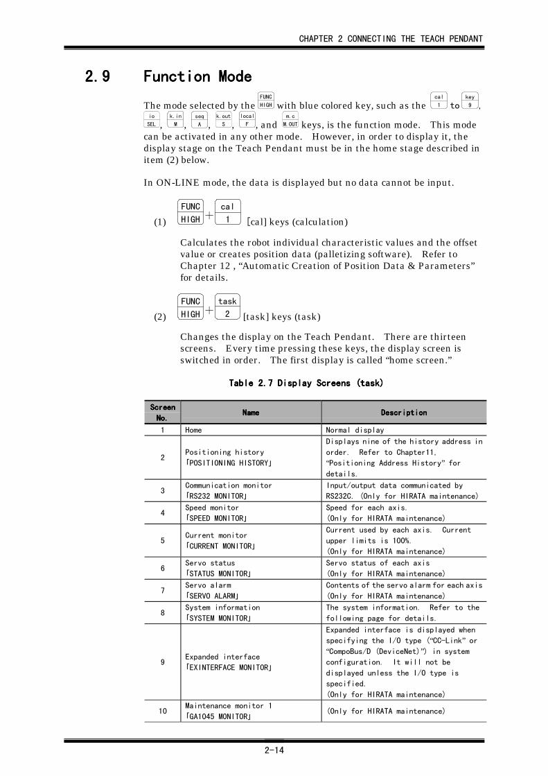
Changes the display on the Teach Pendant. There are thirteenscreens. Every time pressing these keys, the display screen isswitched in order. The first display is called “home screen.”
Table 2.Table 2.Table 2.Table 2.7777 Display Screens (task) Display Screens (task) Display Screens (task) Display Screens (task)
ScreenScreenScreenScreen
No.No.No.No.NameNameNameName DescriptionDescriptionDescriptionDescription
1 Home Normal display
2Positioning history
「POSITIONING HISTORY」
Displays nine of the history address in
order. Refer to Chapter11,
“Positioning Address History” fordetails.
3Communication monitor
「RS232 MONITOR」
Input/output data communicated by
RS232C. (Only for HIRATA maintenance)
4Speed monitor
「SPEED MONITOR」
Speed for each axis.
(Only for HIRATA maintenance)
5Current monitor
「CURRENT MONITOR」
Current used by each axis. Current
upper limits is 100%.
(Only for HIRATA maintenance)
6Servo status
「STATUS MONITOR」
Servo status of each axis
(Only for HIRATA maintenance)
7Servo alarm
「SERVO ALARM」
Contents of the servo alarm for each axis
(Only for HIRATA maintenance)
8System information
「SYSTEM MONITOR」
The system information. Refer to the
following page for details.
9Expanded interface
「EXINTERFACE MONITOR」
Expanded interface is displayed when
specifying the I/O type (“CC-Link” or“CompoBus/D (DeviceNet)”) in systemconfiguration. It will not be
displayed unless the I/O type is
specified.
(Only for HIRATA maintenance)
10Maintenance monitor 1
「GA1045 MONITOR」(Only for HIRATA maintenance)
CHAPTER 2 CONNECTING THE TEACH PENDANT
2-15
ScreenScreenScreenScreen
No.No.No.No.NameNameNameName DescriptionDescriptionDescriptionDescription
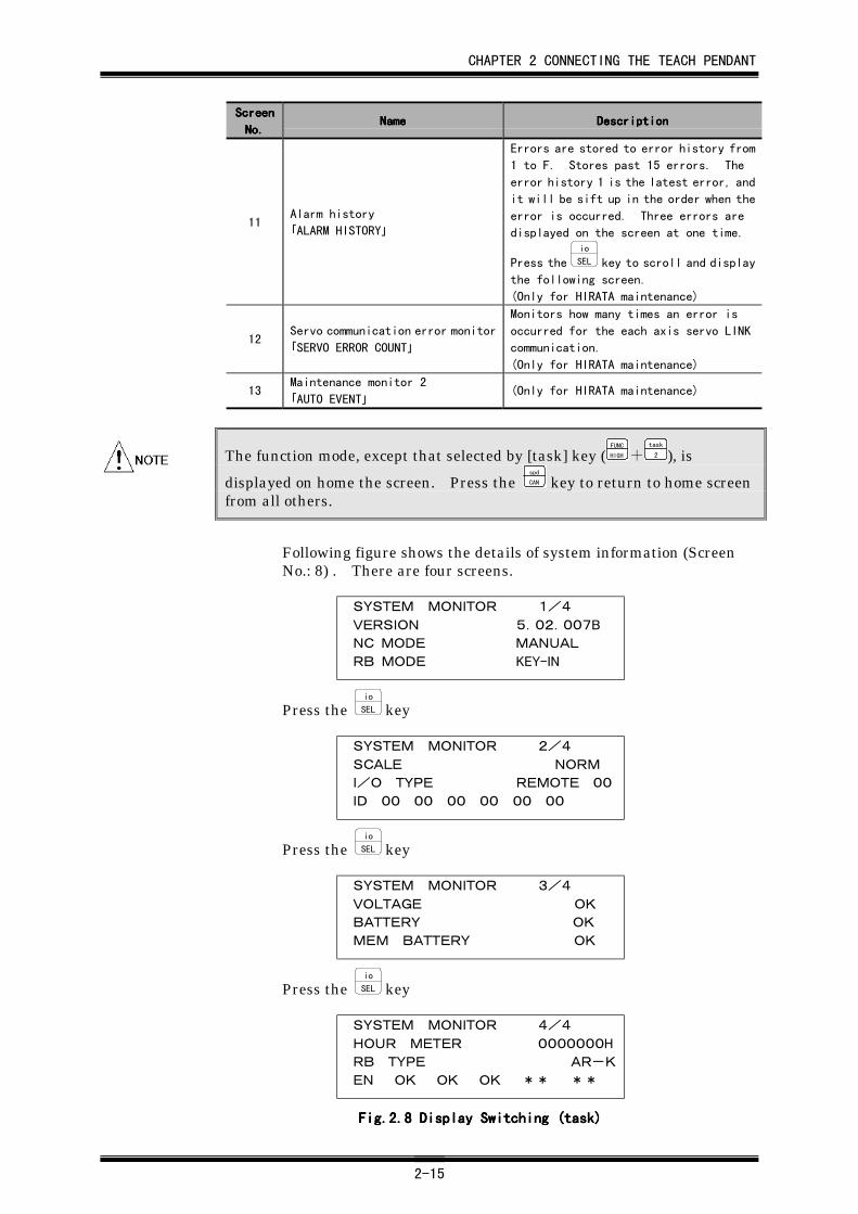
11Alarm history
「ALARM HISTORY」
Errors are stored to error history from
1 to F. Stores past 15 errors. The
error history 1 is the latest error, and
it will be sift up in the order when the
error is occurred. Three errors are
displayed on the screen at one time.
Press the io
SEL key to scroll and display
the following screen.
(Only for HIRATA maintenance)
12Servo communication error monitor
「SERVO ERROR COUNT」
Monitors how many times an error is
occurred for the each axis servo LINK
communication.
(Only for HIRATA maintenance)
13Maintenance monitor 2
「AUTO EVENT」(Only for HIRATA maintenance)
The function mode, except that selected by [task] key (FUNC
HIGH +task
2 ), is
displayed on home the screen. Press the spd
CAN key to return to home screenfrom all others.
Following figure shows the details of system information (ScreenNo.: 8) . There are four screens.
SYSTEM MONITOR 1/4
VERSION 5.02.007B
NC MODE MANUAL
RB MODE KEY-IN
Press the io
SEL key
SYSTEM MONITOR 2/4
SCALE NORM
I/O TYPE REMOTE 00
ID 00 00 00 00 00 00
Press the io
SEL key
SYSTEM MONITOR 3/4
VOLTAGE OK
BATTERY OK
MEM BATTERY OK
Press the io
SEL key
SYSTEM MONITOR 4/4
HOUR METER 0000000H
RB TYPE AR-K
EN OK OK OK ** **
Fig.2.Fig.2.Fig.2.Fig.2.8888 Display Switching (task) Display Switching (task) Display Switching (task) Display Switching (task)
CHAPTER 2 CONNECTING THE TEACH PENDANT
2-16
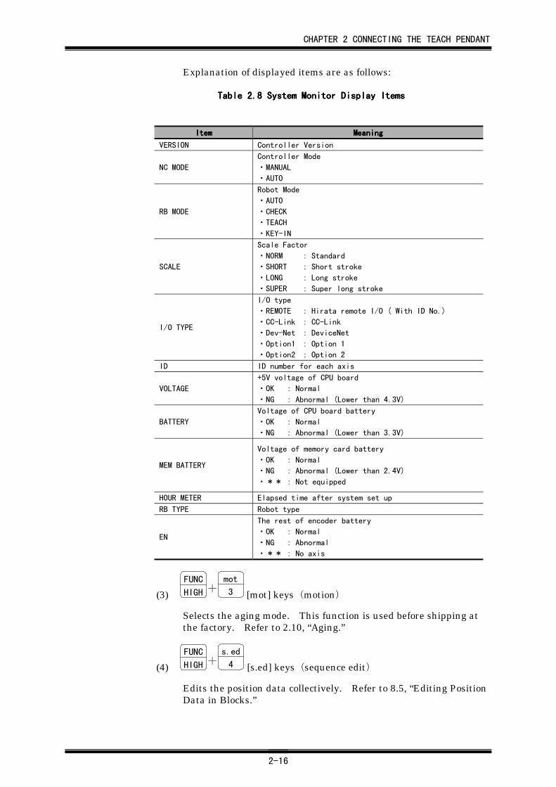
Explanation of displayed items are as follows:
Table 2.Table 2.Table 2.Table 2.8888 System Monitor Display Items System Monitor Display Items System Monitor Display Items System Monitor Display Items
ItemItemItemItem MeaningMeaningMeaningMeaning
VERSION Controller Version
NC MODE
Controller Mode
・MANUAL
・AUTO
RB MODE
Robot Mode
・AUTO
・CHECK
・TEACH
・KEY-IN
SCALE
Scale Factor
・NORM : Standard
・SHORT : Short stroke
・LONG : Long stroke
・SUPER : Super long stroke
I/O TYPE
I/O type
・REMOTE : Hirata remote I/O ( With ID No.)
・CC-Link : CC-Link
・Dev-Net : DeviceNet
・Option1 : Option 1
・Option2 : Option 2
ID ID number for each axis
VOLTAGE
+5V voltage of CPU board
・OK : Normal
・NG : Abnormal (Lower than 4.3V)
BATTERY
Voltage of CPU board battery
・OK : Normal
・NG : Abnormal (Lower than 3.3V)
MEM BATTERY
Voltage of memory card battery
・OK : Normal
・NG : Abnormal (Lower than 2.4V)
・** : Not equipped
HOUR METER Elapsed time after system set up
RB TYPE Robot type
EN
The rest of encoder battery
・OK : Normal
・NG : Abnormal
・** : No axis
(3) FUNC
HIGH +mot
3 [mot] keys(motion)
Selects the aging mode. This function is used before shipping atthe factory. Refer to 2.10, “Aging.”
(4) FUNC
HIGH +s.ed
4 [s.ed] keys(sequence edit)
Edits the position data collectively. Refer to 8.5, “Editing PositionData in Blocks.”
CHAPTER 2 CONNECTING THE TEACH PENDANT
2-17
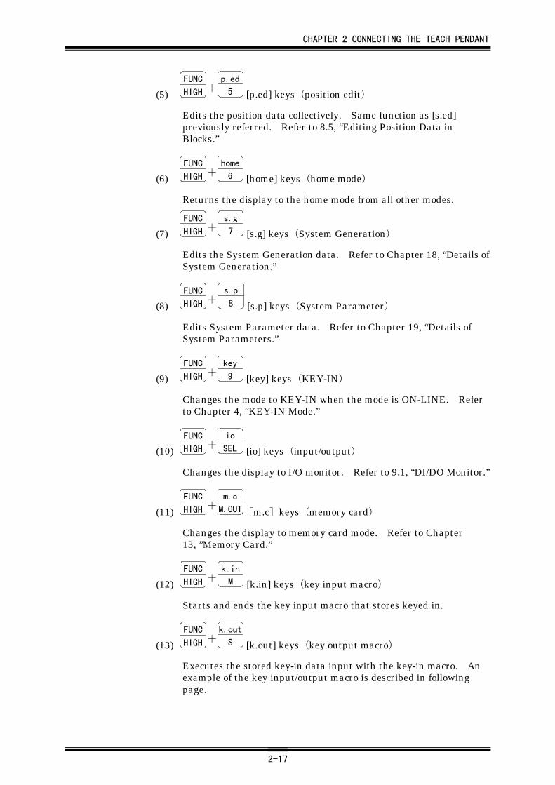
(5) FUNC
HIGH +p.ed
5 [p.ed] keys(position edit)
Edits the position data collectively. Same function as [s.ed]previously referred. Refer to 8.5, “Editing Position Data inBlocks.”
(6) FUNC
HIGH +home
6 [home] keys(home mode)
Returns the display to the home mode from all other modes.
(7) FUNC
HIGH +s.g
7 [s.g] keys(System Generation)
Edits the System Generation data. Refer to Chapter 18, “Details ofSystem Generation.”
(8) FUNC
HIGH +s.p
8 [s.p] keys(System Parameter)
Edits System Parameter data. Refer to Chapter 19, “Details ofSystem Parameters.”
(9) FUNC
HIGH +key
9 [key] keys(KEY-IN)
Changes the mode to KEY-IN when the mode is ON-LINE. Referto Chapter 4, “KEY-IN Mode.”
(10) FUNC
HIGH +io
SEL [io] keys(input/output)
Changes the display to I/O monitor. Refer to 9.1, “DI/DO Monitor.”
(11) FUNC
HIGH +m.c
M.OUT[m.c]keys(memory card)
Changes the display to memory card mode. Refer to Chapter13, ”Memory Card.”
(12) FUNC
HIGH +k.in
M [k.in] keys(key input macro)
Starts and ends the key input macro that stores keyed in.
(13) FUNC
HIGH +k.out
S [k.out] keys(key output macro)
Executes the stored key-in data input with the key-in macro. Anexample of the key input/output macro is described in followingpage.
CHAPTER 2 CONNECTING THE TEACH PENDANT
2-18
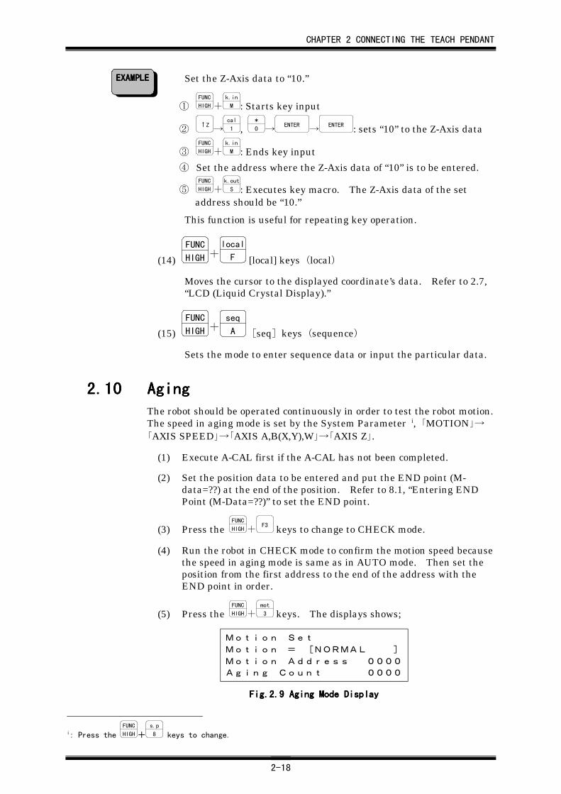
Set the Z-Axis data to “10.”
① FUNC
HIGH+k.in
M : Starts key input
② ↑Z→
cal
1 , *
0 →ENTER
→ENTER : sets “10” to the Z-Axis data
③ FUNC
HIGH+k.in
M : Ends key input
④ Set the address where the Z-Axis data of “10” is to be entered.
⑤ FUNC
HIGH+k.out
S : Executes key macro. The Z-Axis data of the setaddress should be “10.”
This function is useful for repeating key operation.
(14) FUNC
HIGH +local
F [local] keys(local)
Moves the cursor to the displayed coordinate’s data. Refer to 2.7,“LCD (Liquid Crystal Display).”
(15) FUNC
HIGH +seq
A [seq]keys(sequence)
Sets the mode to enter sequence data or input the particular data.
2.102.102.102.10 AgingAgingAgingAgingThe robot should be operated continuously in order to test the robot motion.The speed in aging mode is set by the System Parameter i, 「MOTION」→「AXIS SPEED」→「AXIS A,B(X,Y),W」→「AXIS Z」.
(1) Execute A-CAL first if the A-CAL has not been completed.
(2) Set the position data to be entered and put the END point (M-data=??) at the end of the position. Refer to 8.1, “Entering ENDPoint (M-Data=??)” to set the END point.
(3) Press the FUNC
HIGH+F3 keys to change to CHECK mode.
(4) Run the robot in CHECK mode to confirm the motion speed becausethe speed in aging mode is same as in AUTO mode. Then set theposition from the first address to the end of the address with theEND point in order.
(5) Press the FUNC
HIGH+mot
3 keys. The displays shows;
Motion Set
Motion = [NORMAL ]
Motion Address 0000
Aging Count 0000
Fig.2.Fig.2.Fig.2.Fig.2.9999 Aging Mode Display Aging Mode Display Aging Mode Display Aging Mode Display
i: Press the FUNC
HIGH+s.p
8 keys to change.
EXAMPLEEXAMPLEEXAMPLEEXAMPLE
CHAPTER 2 CONNECTING THE TEACH PENDANT
2-19
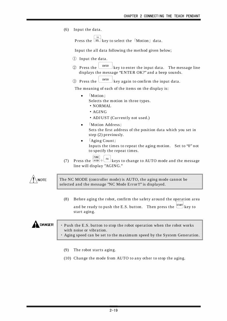
(6) Input the data.
Press the io
SEL key to select the 「Motion」 data.
Input the all data following the method given below;
① Input the data.
② Press the ENTER key to enter the input data. The message linedisplays the message “ENTER OK?” and a beep sounds.
③ Press the ENTER key again to confirm the input data.
The meaning of each of the items on the display is:
• 「Motion」Selects the motion in three types.・NORMAL・AGING・ADJUST (Currently not used.)
• 「Motion Address」Sets the first address of the position data which you set instep (2) previously.
• 「Aging Count」Inputs the times to repeat the aging motion. Set to “0” notto specify the repeat times.
(7) Press the FUNC
HIGH+F4 keys to change to AUTO mode and the message
line will display ”AGING.”
The NC MODE (controller mode) is AUTO, the aging mode cannot beselected and the message ”NC Mode Error!!” is displayed.
(8) Before aging the robot, confirm the safety around the operation area
and be ready to push the E.S. button. Then press the START key tostart aging.
・ Push the E.S. button to stop the robot operation when the robot workswith noise or vibration.
・ Aging speed can be set to the maximum speed by the System Generation.
(9) The robot starts aging.
(10) Change the mode from AUTO to any other to stop the aging.
CHAPTER 3 A-CAL(AUTOMATIC CALIBRATION)
3-1
CHAPTER 3CHAPTER 3CHAPTER 3CHAPTER 3 A-CALA-CALA-CALA-CAL((((Automatic CalibrationAutomatic CalibrationAutomatic CalibrationAutomatic Calibration))))
3.13.13.13.1 Basic OperationBasic OperationBasic OperationBasic OperationIt is necessary to perform A-CAL (Automatic calibration) and light the 『A-CAL』 LED on the Teach Pendant before the robot operation. The positionof each axis is detected by counting the encoder pulse generated from theencoder which is connected each axis. The encoder and counter do notcount the encoder pulse unless the controller has been connected to thepower supply.
The robot must know the current position in physically and electronically.Generally, all the mechanism requires, so-called calibration, which is tomatch the coordinate data in the controller and physical robot position.
A-CAL automatically brings about the coincidence of the two origins.
Once A-CAL is done after turning ON the power, it is not necessary torepeat the A-CAL procedure as long as the 『A-CAL』 LED remains ON.
The 580 series controller uses the ABS (Absolute) encoder to detect theposition, so that the A-CAL is performed only once when the robot isinstalled. That is, it is not necessary to perform A-CAL again after the firstA-CAL.
If the driver error “U” has occurred, set 「A-CAL CHEK」 in SystemGeneration menu to ”0” and perform A-CAL again to escape from this error.Refer to 3.2, “A-CAL Parameters” for details.
CHAPTER 3 A-CAL(AUTOMATIC CALIBRATION)
3-2
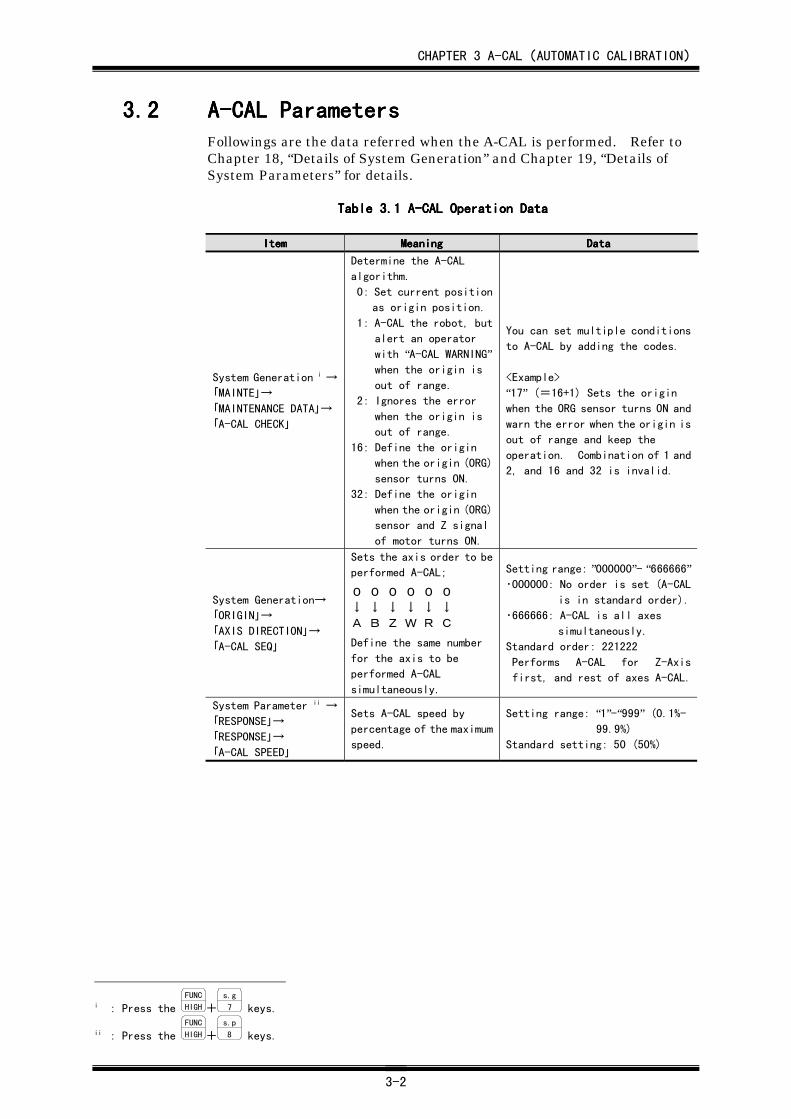
3.23.23.23.2 A-CAL ParametersA-CAL ParametersA-CAL ParametersA-CAL ParametersFollowings are the data referred when the A-CAL is performed. Refer toChapter 18, “Details of System Generation” and Chapter 19, “Details ofSystem Parameters” for details.
TableTableTableTable 3. 3. 3. 3.1111 A-CAL Operation Data A-CAL Operation Data A-CAL Operation Data A-CAL Operation Data
ItemItemItemItem MeaningMeaningMeaningMeaning DataDataDataData
System Generation i →
「MAINTE」→
「MAINTENANCE DATA」→
「A-CAL CHECK」
Determine the A-CAL
algorithm.
0: Set current position
as origin position.
1: A-CAL the robot, but
alert an operator
with “A-CAL WARNING”when the origin is
out of range.
2: Ignores the error
when the origin is
out of range.
16: Define the origin
when the origin (ORG)
sensor turns ON.
32: Define the origin
when the origin (ORG)
sensor and Z signal
of motor turns ON.
You can set multiple conditions
to A-CAL by adding the codes.
<Example>
“17” (=16+1) Sets the originwhen the ORG sensor turns ON and
warn the error when the origin is
out of range and keep the
operation. Combination of 1 and
2, and 16 and 32 is invalid.
System Generation→
「ORIGIN」→
「AXIS DIRECTION」→
「A-CAL SEQ」
Sets the axis order to be
performed A-CAL;
0 0 0 0 0 0↓ ↓ ↓ ↓ ↓ ↓A B Z W R C
Define the same number
for the axis to be
performed A-CAL
simultaneously.
Setting range: ”000000”- “666666”・000000: No order is set (A-CAL
is in standard order).
・666666: A-CAL is all axes
simultaneously.
Standard order: 221222
Performs A-CAL for Z-Axis
first, and rest of axes A-CAL.
System Parameter ii →
「RESPONSE」→
「RESPONSE」→
「A-CAL SPEED」
Sets A-CAL speed by
percentage of the maximum
speed.
Setting range: “1”-“999” (0.1%-99.9%)
Standard setting: 50 (50%)
i : Press the FUNC
HIGH+s.g
7 keys.
ii : Press the FUNC
HIGH+s.p
8 keys.
CHAPTER 3 A-CAL(AUTOMATIC CALIBRATION)
3-3
3.33.33.33.3 A-CAL ProcedureA-CAL ProcedureA-CAL ProcedureA-CAL Procedure
Press the A-CAL key to perform A-CAL in TEACH and CHECK mode. In theautomatic operation, A-CAL is performed by the commands, such asSELECT signal in AUTO mode and A-CAL command in ON-LINE mode,from external devices. Refer to 2.4, “Mode Select Operation,” about therobot modes. The following is the manual A-CAL procedure to beperformed with the Teach Pendant.
(1) Set the Teach Pendant to TEACH or CHECK mode. A-CAL can beperformed in both modes by the same procedure.
(2) Make sure not to release the Deadman switch during the followingoperation. Releasing the Deadman switch causes the system to gointo Emergency Stop status.
(3) Set the position data display by pulse.
① Press the FUNC
HIGH+local
F keys.
② Press the key
9 key.
③ Press the READ key
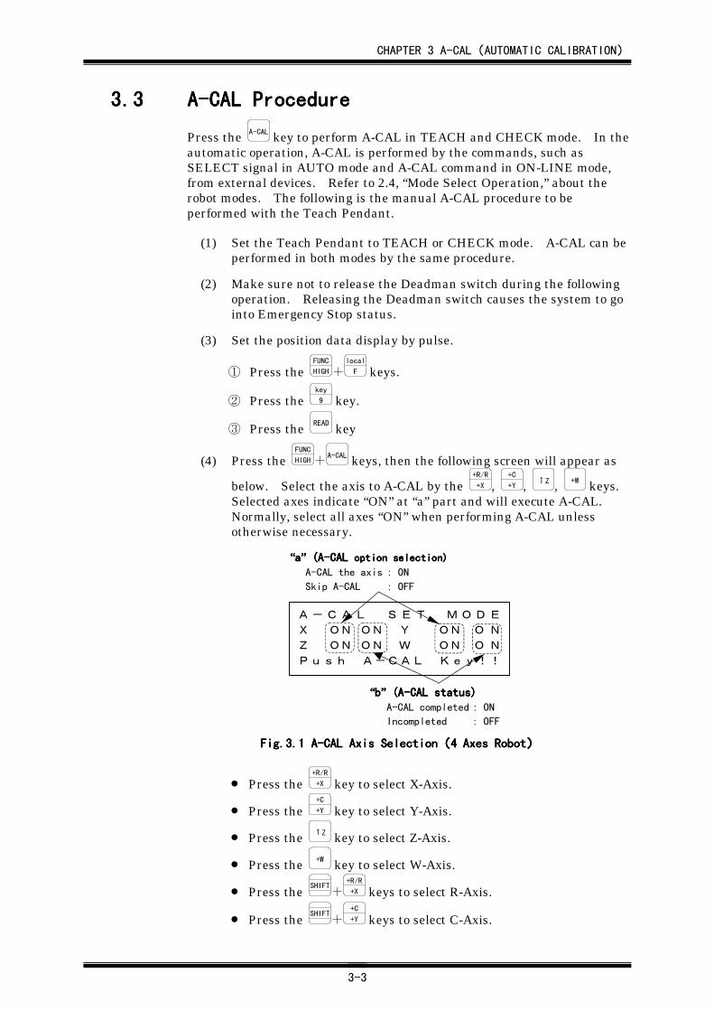
(4) Press the FUNC
HIGH+A-CAL keys, then the following screen will appear as
below. Select the axis to A-CAL by the +R/R
+X , +C
+Y , ↑Z , +W keys.Selected axes indicate “ON” at “a” part and will execute A-CAL.Normally, select all axes “ON” when performing A-CAL unlessotherwise necessary.
A-CAL SET MODE
X ON ON Y ON O N
Z ON ON W ON O N
Push A-CAL Key!!
““““bbbb”””” (A-CAL status) (A-CAL status) (A-CAL status) (A-CAL status)A-CAL completed : ON
Incompleted : OFF
““““aaaa”””” (A-CAL (A-CAL (A-CAL (A-CAL option selection)option selection)option selection)option selection)
A-CAL the axis : ON
Skip A-CAL : OFF
Fig.Fig.Fig.Fig.3.3.3.3.1111 A-CAL Axis Selection A-CAL Axis Selection A-CAL Axis Selection A-CAL Axis Selection((((4 Axes Robot4 Axes Robot4 Axes Robot4 Axes Robot))))
• Press the +R/R
+X key to select X-Axis.
• Press the +C
+Y key to select Y-Axis.
• Press the ↑Z key to select Z-Axis.
• Press the +W key to select W-Axis.
• Press the SHIFT+
+R/R
+X keys to select R-Axis.
• Press the SHIFT+
+C
+Y keys to select C-Axis.
CHAPTER 3 A-CAL(AUTOMATIC CALIBRATION)
3-4
(5) Keep pressing the A-CAL key until the A-CAL completes.
(6) When A-CAL is completed successfully, “A-CAL COMPLETED”willbe appeared on screen and a buzzer will sound. If A-CAL could notbe completed for some reason, “A-CAL INCOMPLETE”will beappeared and a buzzer will sound. Repeat from step (2) in the caseof A-CAL incomplete. Once A-CAL is done, the 『A-CAL』 LEDlights.
(7) Verify the A-CAL results. Take note of the current encoder pulsecount on the screen.
To display the pulse count;
① Press the FUNC
HIGH+local
F keys.
② Press the key
9 key.
③ Press the READ key.
(8) Turn OFF the power.
(9) Turn ON the power again.
(10) Compare the current encoder pulse and recorded pulse at step (7).If the pulse difference is less than 100 pulse, A-CAL is donesuccessfully. If the difference is exceeding 100 pulse, go back tostep (2) above.
Releasing the A-CAL key before A-CAL complete, the robot stops the A-CALoperation and “A-CAL INCOMPLETE” is displayed and a buzzer will sound.Perform A-CAL operation again from step (2) above.
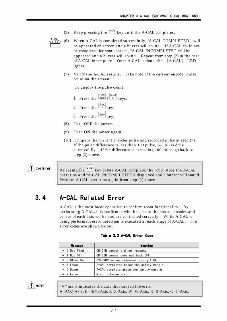
3.43.43.43.4 A-CAL Related ErrorA-CAL Related ErrorA-CAL Related ErrorA-CAL Related ErrorA-CAL is the most basic operation to confirm robot functionality. Byperforming A-CAL, it is confirmed whether or not the motor, encoder andsensor of each axis works and are controlled correctly. While A-CAL isbeing performed, error detection is executed at each stage of A-CAL. Theerror codes are shown below.
TableTableTableTable 3. 3. 3. 3.2222 A-CAL Error Code A-CAL Error Code A-CAL Error Code A-CAL Error Code
MessageMessageMessageMessage MeaningMeaningMeaningMeaning
* 0 Not Find ORIGIN sensor did not respond.
* 1 Not Off ORIGIN sensor does not back OFF.
* 2 Other On OVERRUN sensor response during A-CAL.
* 4 Lower A-CAL completed below the safety margin.
* 5 Upper A-CAL complete above the safety margin
* 7 Error Misc. unknown error.
“*” mark indicates the axis that caused the error.A=A(X)-Axis, B=B(Y)-Axis Z=Z-Axis, W=W-Axis, R=R-Axis, C=C-Axis.
A-CAL
CHAPTER 3 A-CAL(AUTOMATIC CALIBRATION)
3-5
3.4.13.4.13.4.13.4.1 User Action for User Action for User Action for User Action for ““““****0 Not Find0 Not Find0 Not Find0 Not Find””””This error means missing ORIGIN sensor signal input. Take followingsteps to resolve the problem. Possibly, the sensor did not react ormechanically the robot did not move onto the sensor.
(1) Retry A-CAL and monitor the robot motion. Verify there is nomechanical jam, slip or broken timing belt which causes mechanicalfailure. If you find a problem, take the necessary actions to correctit.
(2) Move the robot to verify the sensor turns ON.
① Go to RO-TEACH mode.② Press the minus (-) axis key to move the robot until the ORIGIN
sensor reacts.
• -R/L
-X key : X (A)-Axis moves toward ORIGIN sensordirection.
• -C
-Y key : Y(B)-Axis moves toward ORIGIN sensordirection.
• ↑Z key : Z-Axis moves toward ORIGIN sensordirection.
• -W key : W-Axis moves toward ORIGIN sensordirection.
• SHIFT+
-R/L
-X keys : R-Axis moves toward ORIGIN sensordirection.
• SHIFT+
-C
-Y keys : C-Axis moves toward ORIGIN sensordirection.
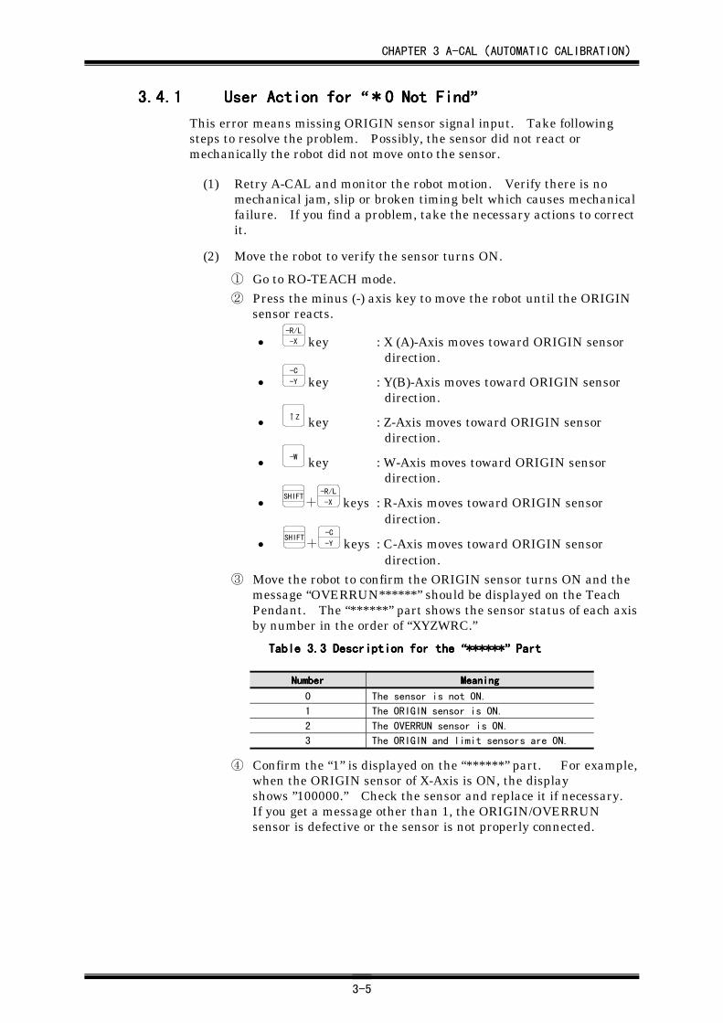
③ Move the robot to confirm the ORIGIN sensor turns ON and themessage “OVERRUN******” should be displayed on the TeachPendant. The “******” part shows the sensor status of each axisby number in the order of “XYZWRC.”
TableTableTableTable 3. 3. 3. 3.3333 Description for the Description for the Description for the Description for the ““““************************”””” Part Part Part Part
NumberNumberNumberNumber MeaningMeaningMeaningMeaning
0 The sensor is not ON.
1 The ORIGIN sensor is ON.
2 The OVERRUN sensor is ON.
3 The ORIGIN and limit sensors are ON.
④ Confirm the “1” is displayed on the “******” part. For example,when the ORIGIN sensor of X-Axis is ON, the displayshows ”100000.” Check the sensor and replace it if necessary.If you get a message other than 1, the ORIGIN/OVERRUNsensor is defective or the sensor is not properly connected.
CHAPTER 3 A-CAL(AUTOMATIC CALIBRATION)
3-6
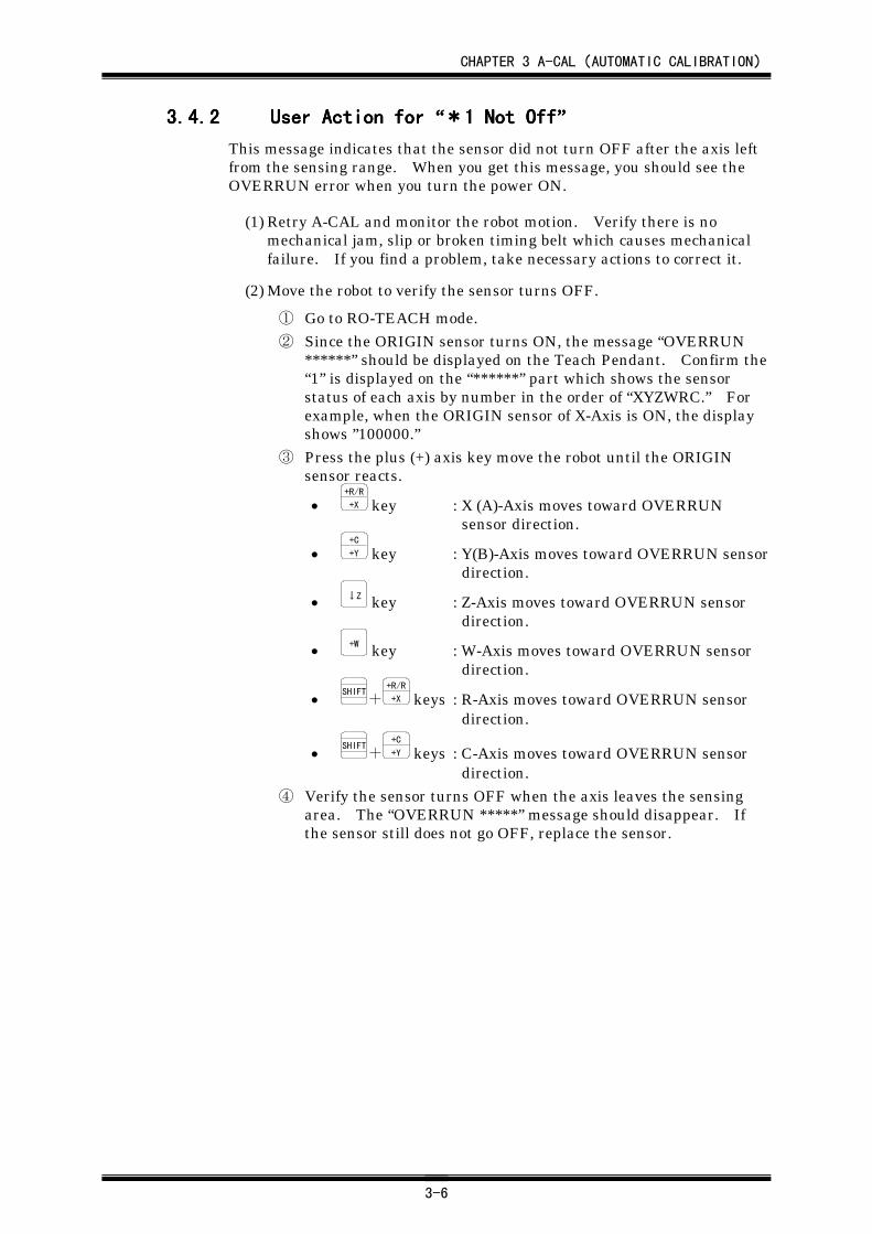
3.4.23.4.23.4.23.4.2 User Action for User Action for User Action for User Action for ““““****1 Not Off1 Not Off1 Not Off1 Not Off””””This message indicates that the sensor did not turn OFF after the axis leftfrom the sensing range. When you get this message, you should see theOVERRUN error when you turn the power ON.
(1) Retry A-CAL and monitor the robot motion. Verify there is nomechanical jam, slip or broken timing belt which causes mechanicalfailure. If you find a problem, take necessary actions to correct it.
(2) Move the robot to verify the sensor turns OFF.
① Go to RO-TEACH mode.② Since the ORIGIN sensor turns ON, the message “OVERRUN
******” should be displayed on the Teach Pendant. Confirm the“1” is displayed on the “******” part which shows the sensorstatus of each axis by number in the order of “XYZWRC.” Forexample, when the ORIGIN sensor of X-Axis is ON, the displayshows ”100000.”
③ Press the plus (+) axis key move the robot until the ORIGINsensor reacts.
• +R/R
+X key : X (A)-Axis moves toward OVERRUNsensor direction.
• +C
+Y key : Y(B)-Axis moves toward OVERRUN sensordirection.
• ↓Z key : Z-Axis moves toward OVERRUN sensordirection.
• +W key : W-Axis moves toward OVERRUN sensordirection.
• SHIFT+
+R/R
+X keys : R-Axis moves toward OVERRUN sensordirection.
• SHIFT+
+C
+Y keys : C-Axis moves toward OVERRUN sensordirection.
④ Verify the sensor turns OFF when the axis leaves the sensingarea. The “OVERRUN *****” message should disappear. Ifthe sensor still does not go OFF, replace the sensor.
CHAPTER 3 A-CAL(AUTOMATIC CALIBRATION)
3-7
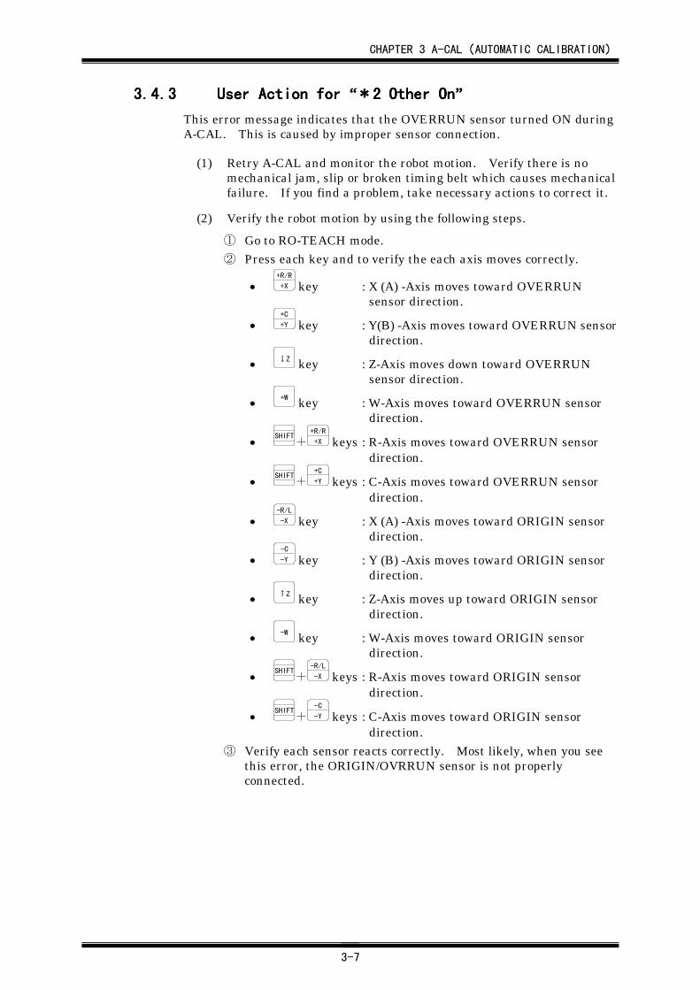
3.4.33.4.33.4.33.4.3 User Action for User Action for User Action for User Action for ““““****2 Other On2 Other On2 Other On2 Other On””””This error message indicates that the OVERRUN sensor turned ON duringA-CAL. This is caused by improper sensor connection.
(1) Retry A-CAL and monitor the robot motion. Verify there is nomechanical jam, slip or broken timing belt which causes mechanicalfailure. If you find a problem, take necessary actions to correct it.
(2) Verify the robot motion by using the following steps.
① Go to RO-TEACH mode.② Press each key and to verify the each axis moves correctly.
• +R/R
+X key : X (A) -Axis moves toward OVERRUNsensor direction.
• +C
+Y key : Y(B) -Axis moves toward OVERRUN sensordirection.
• ↓Z key : Z-Axis moves down toward OVERRUNsensor direction.
• +W key : W-Axis moves toward OVERRUN sensordirection.
• SHIFT+
+R/R
+X keys : R-Axis moves toward OVERRUN sensordirection.
• SHIFT+
+C
+Y keys : C-Axis moves toward OVERRUN sensordirection.
• -R/L
-X key : X (A) -Axis moves toward ORIGIN sensordirection.
• -C
-Y key : Y (B) -Axis moves toward ORIGIN sensordirection.
• ↑Z key : Z-Axis moves up toward ORIGIN sensordirection.
• -W key : W-Axis moves toward ORIGIN sensordirection.
• SHIFT+
-R/L
-X keys : R-Axis moves toward ORIGIN sensordirection.
• SHIFT+
-C
-Y keys : C-Axis moves toward ORIGIN sensordirection.
③ Verify each sensor reacts correctly. Most likely, when you seethis error, the ORIGIN/OVRRUN sensor is not properlyconnected.
CHAPTER 3 A-CAL(AUTOMATIC CALIBRATION)
3-8
3.4.43.4.43.4.43.4.4 User Action for User Action for User Action for User Action for ““““*4 Lower*4 Lower*4 Lower*4 Lower””””Sensor tab is adjusted lower than safety margin. To correct the positiondrift, it is recommended to adjust the sensor tab position.
This error indicates that A-CAL is completed when the encoder pulse countis less than 2,048. The position of the sensor and sensor tab should be setso that the ORIGIN sensor turns ON between 2,048~6,144 pulses.
3.4.53.4.53.4.53.4.5 User Action for User Action for User Action for User Action for ““““*5 Upper*5 Upper*5 Upper*5 Upper””””Sensor tab is adjusted lower than safety margin. To correct the positiondrift, it is recommended to adjust the sensor tab position.
This error indicates that A-CAL is completed when the encoder pulse countis greater than 6,144. The position of the sensor and sensor tab should beset so that the ORIGIN sensor turns ON between 2,048~6,144 pulses.
3.4.63.4.63.4.63.4.6 User Action for User Action for User Action for User Action for ““““OVERRUN ******OVERRUN ******OVERRUN ******OVERRUN ******””””The OVERRUN sensor maybe disconnected. Check the sensor connection.However the “OVERRUN ******” error during the procedure abovementioned to recover from A-CAL error is a normal message.
CHAPTER 4 KEY-IN MODE
4-1
CHAPTER 4CHAPTER 4CHAPTER 4CHAPTER 4 KEY-IN ModeKEY-IN ModeKEY-IN ModeKEY-IN Mode
4.14.14.14.1 GeneralGeneralGeneralGeneralKEY-IN mode enables you to enter the position data with the numeric keysmanually.
Set the controller mode to MANUAL and press the FUNC
HIGH+F1 keys to enter
KEY-IN mode. Also, it is able to enter KEY-IN mode by pressing the FUNC
HIGH
+key
9 keys in AUTO mode.
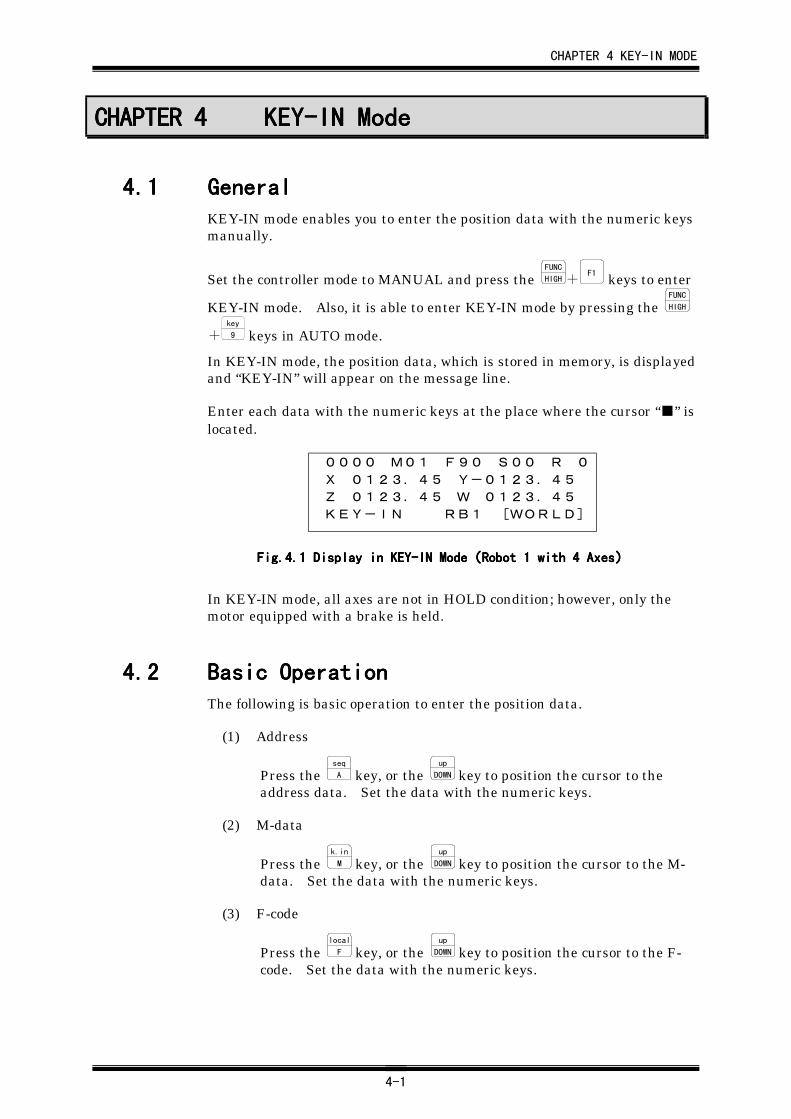
In KEY-IN mode, the position data, which is stored in memory, is displayedand “KEY-IN” will appear on the message line.
Enter each data with the numeric keys at the place where the cursor “■” islocated.
0000 M01 F90 S00 R 0
X 0123.45 Y-0123.45
Z 0123.45 W 0123.45
KEY-IN RB1 [WORLD]
Fig.Fig.Fig.Fig.4.4.4.4.1111 Display in KEY-IN Mode Display in KEY-IN Mode Display in KEY-IN Mode Display in KEY-IN Mode((((Robot 1 with 4 AxesRobot 1 with 4 AxesRobot 1 with 4 AxesRobot 1 with 4 Axes))))
In KEY-IN mode, all axes are not in HOLD condition; however, only themotor equipped with a brake is held.
4.24.24.24.2 Basic OperationBasic OperationBasic OperationBasic OperationThe following is basic operation to enter the position data.
(1) Address
Press the seq
A key, or the up
DOWN key to position the cursor to theaddress data. Set the data with the numeric keys.
(2) M-data
Press the k.in
M key, or the up
DOWN key to position the cursor to the M-data. Set the data with the numeric keys.
(3) F-code
Press the local
F key, or the up
DOWN key to position the cursor to the F-code. Set the data with the numeric keys.
CHAPTER 4 KEY-IN MODE
4-2
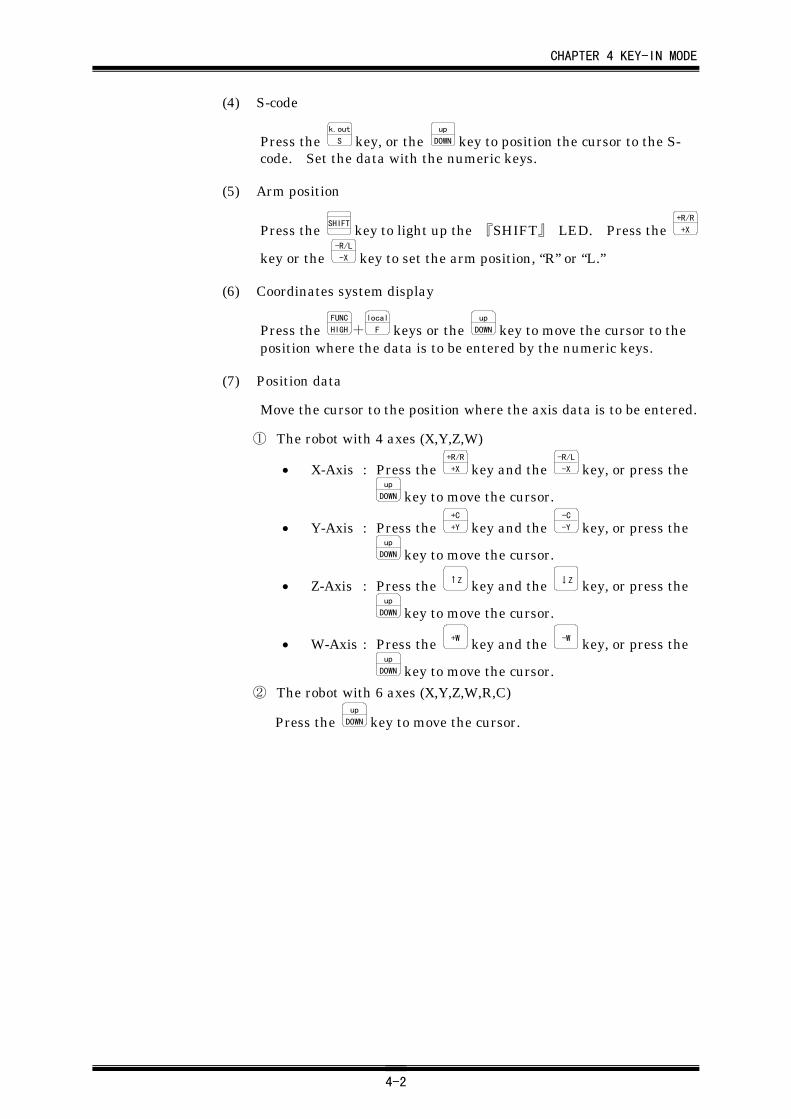
(4) S-code
Press the k.out
S key, or the up
DOWN key to position the cursor to the S-code. Set the data with the numeric keys.
(5) Arm position
Press the SHIFT
key to light up the 『SHIFT』 LED. Press the +R/R
+X
key or the -R/L
-X key to set the arm position, “R” or “L.”
(6) Coordinates system display
Press the FUNC
HIGH+local
F keys or the up
DOWN key to move the cursor to theposition where the data is to be entered by the numeric keys.
(7) Position data
Move the cursor to the position where the axis data is to be entered.
① The robot with 4 axes (X,Y,Z,W)
• X-Axis : Press the +R/R
+X key and the -R/L
-X key, or press theup
DOWN key to move the cursor.
• Y-Axis : Press the +C
+Y key and the -C
-Y key, or press theup
DOWN key to move the cursor.
• Z-Axis : Press the ↑Z key and the ↓Z key, or press theup
DOWN key to move the cursor.
• W-Axis : Press the +W key and the -W key, or press theup
DOWN key to move the cursor.
② The robot with 6 axes (X,Y,Z,W,R,C)
Press the up
DOWN key to move the cursor.
CHAPTER 4 KEY-IN MODE
4-3
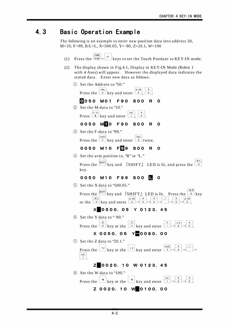
4.34.34.34.3 Basic Operation ExampleBasic Operation ExampleBasic Operation ExampleBasic Operation ExampleThe following is an example to enter new position data into address 50,M=10, F=99, R/L=L, X=500.05, Y=-80, Z=20.1, W=100
(1) Press the FUNC
HIGH+F1 keys to set the Teach Pendant to KEY-IN mode.
(2) The display shown in Fig.4.1, Display in KEY-IN Mode (Robot 1with 4 Axes) will appear. However the displayed data indicates thestored data. Enter new data as follows.
① Set the Address to “50.”
Press the seq
A key and enter p.ed
5 , *
0 .
0000050050050050 M01M01M01M01 F90F90F90F90 S00S00S00S00 RRRR 0000
② Set the M-data to “10.”
Press k.in
M key and enter cal
1 , *
0 .
0050005000500050 MMMM11110000 F90F90F90F90 S00S00S00S00 RRRR 0000
③ Set the F-data to “99.”
Press the local
F key and enter key
9 twice.
0050005000500050 M10M10M10M10 FFFF99999999 S00S00S00S00 RRRR 0000
④ Set the arm position to, “R” or “L.”
Press the SHIFT
key and 『SHIFT』 LED is lit, and press the -R/L
-X
key.
0050005000500050 M10M10M10M10 F99F99F99F99 S00S00S00S00 LLLL 0000
⑤ Set the X data to “500.05.”
Press the SHIFT
key and 『SHIFT』 LED is lit. Press the +R/R
+X key
or the -R/L
-X key and enter p.ed
5 →*
0 →*
0 →/
. →*
0 →p.ed
5 .
XXXX 0500.050500.050500.050500.05 YYYY 0123.450123.450123.450123.45
⑥ Set the Y data to “-80.”
Press the +C
+Y key or the -C
-Y key and enter +
- →s.p
8 →*
0 .
XXXX 0050.050050.050050.050050.05 YYYY----0080.000080.000080.000080.00
⑦ Set the Z data to “20.1.”
Press the ↑Z key or the ↓Z key and enter task
2 →*
0 →/
. →cal
1 .
ZZZZ 0020.100020.100020.100020.10 WWWW 0123.450123.450123.450123.45
⑧ Set the W data to “100.”
Press the +W key or the -W key and enter cal
1 →*
0 →*
0 .
ZZZZ 0020.100020.100020.100020.10 WWWW 0100.000100.000100.000100.00
CHAPTER 4 KEY-IN MODE
4-4
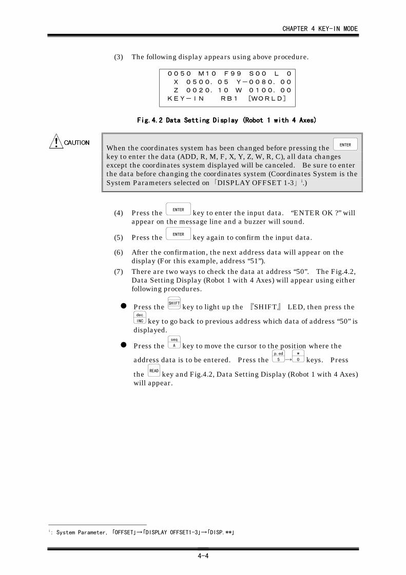
(3) The following display appears using above procedure.
0050 M10 F99 S00 L 0
X 0500.05 Y-0080.00
Z 0020.10 W 0100.00
KEY-IN RB1 [WORLD]
Fig.4Fig.4Fig.4Fig.4....2222 Data Setting Display (Robot 1 with 4 Axes)Data Setting Display (Robot 1 with 4 Axes)Data Setting Display (Robot 1 with 4 Axes)Data Setting Display (Robot 1 with 4 Axes)
When the coordinates system has been changed before pressing the ENTER
key to enter the data (ADD, R, M, F, X, Y, Z, W, R, C), all data changesexcept the coordinates system displayed will be canceled. Be sure to enterthe data before changing the coordinates system (Coordinates System is theSystem Parameters selected on「DISPLAY OFFSET 1-3」i.)
(4) Press the ENTER key to enter the input data. “ENTER OK ?” willappear on the message line and a buzzer will sound.
(5) Press the ENTER key again to confirm the input data.
(6) After the confirmation, the next address data will appear on thedisplay (For this example, address “51”).
(7) There are two ways to check the data at address “50”. The Fig.4.2,Data Setting Display (Robot 1 with 4 Axes) will appear using eitherfollowing procedures.
Press the SHIFT
key to light up the 『SHIFT』 LED, then press thedec
INC key to go back to previous address which data of address “50” isdisplayed.
Press the seq
A key to move the cursor to the position where the
address data is to be entered. Press the p.ed
5 →*
0 keys. Press
the READ key and Fig.4.2, Data Setting Display (Robot 1 with 4 Axes)will appear.
i: System Parameter, 「OFFSET」→「DISPLAY OFFSET1-3」→「DISP.**」
CHAPTER 4 KEY-IN MODE
4-5
4.44.44.44.4 Data CorrectionData CorrectionData CorrectionData Correction(1) To correct wrong data;
Move the cursor to the position where the correct data is to be inputand entered.
(2) To cancel all data before entering;
Press the READ key and the display shows the data stored in thecurrent address.
(3) When you cancel the entry of all data and start from address “0000”;
Press the spd
CAN key
(4) When you cancel the entry of data;
After “ENTER OK ?” appears on the display, press any key except
the ENTER key.
(5) When an error message appears on the display;
Data cannot be entered. Press the spd
CAN key then the error messagedisappears and the stored data is displayed. After confirming theerror (Refer to Chapter 23, “Message”), enter the correct data.
CHAPTER 5 TEACH MODE
5-1
CHAPTER 5CHAPTER 5CHAPTER 5CHAPTER 5 TEACH ModeTEACH ModeTEACH ModeTEACH Mode
5.15.15.15.1 GeneralGeneralGeneralGeneralThis mode enables you to manipulate the robot and perform teaching byhand or with the axis key i. The axis moves at high speed by pressing each
axis key with the FUNC
HIGH key.
If you press the opposite direction keys (e.g., +R/R
+X , -R/L
-X ) at the same time,the axis does not move.
While operating the robot in TEACH mode, hold the Deadman switch. Ifyou release the Deadman switch, the Emergency Stop function turns ON.
Set the controller mode to MANUAL and press the FUNC
HIGH+F2 keys to
change TEACH mode. There are two modes for TEACH operation, LI-TEACH and RO-TEACH. The LI-TEACH is to manipulate the A,B (X,Y)-Axes linearly along the X-Y coordinates set by the system data. The RO-TEACH is to manipulate each axis independently. When the mode ischanged to TEACH, either mode of LI-TEACH or RO-TEACH will bedesignated by the coordinate system displayed on the Teach Pendant.Refer to 2.4, “Mode Select Operation” for details.
5.25.25.25.2 Basic OperationBasic OperationBasic OperationBasic Operation
5.2.15.2.15.2.15.2.1 Operation with X-Y Coordinates in LI-TEACH Mode.Operation with X-Y Coordinates in LI-TEACH Mode.Operation with X-Y Coordinates in LI-TEACH Mode.Operation with X-Y Coordinates in LI-TEACH Mode.
In LI-TEACH mode, the X (A) and Y (B)-Axes are controlled simultaneouslyand are linearly operated along the X-Y coordinates set at DISPLAYOFFSET ii. The X (A) and Y (B)-Axes moves in parallel with the X
coordinate with the +R/R
+X or the -R/L
-X key and in parallel with the Y
coordinate with the +C
+Y or the -C
-Y key. In linear operation, the W-Axismoves independently and keeps its orientation to the X-Y coordinates.
Unless the 『A-CAL』 LED is lit, you cannot operate the robot in LI-TEACHmode. “A-CAL INCOMPLETE” will appear on the display. Refer toChapter 3, “ A-CAL (Automatic Calibration)” to perform A-CAL.
i : The axis is specified by pressing the +R/R
+X , -R/L
-X , -R/L
-X , -C
-Y , ↑Z
, ↓Z
, +W
,or the -W
key. Refer
to Fig.2.1, “Naming and Function of the Teach Pendant.”ii : Specified by 「OFFSET」→「DISPLAY OFFSET1-3」→「DISP.**」 in System Parameter menu.
A-CAL
CHAPTER 5 TEACH MODE
5-2
5.2.25.2.25.2.25.2.2 X (A) and Y (B)-Axes Operation in RO-TEACH ModeX (A) and Y (B)-Axes Operation in RO-TEACH ModeX (A) and Y (B)-Axes Operation in RO-TEACH ModeX (A) and Y (B)-Axes Operation in RO-TEACH Mode
In RO-TEACH mode, X (A)-Axis is operated by the +R/R
+X or the -R/L
-X key, and
Y (B)-Axis is operated by the -R/L
-X or the -C
-Y key independently.
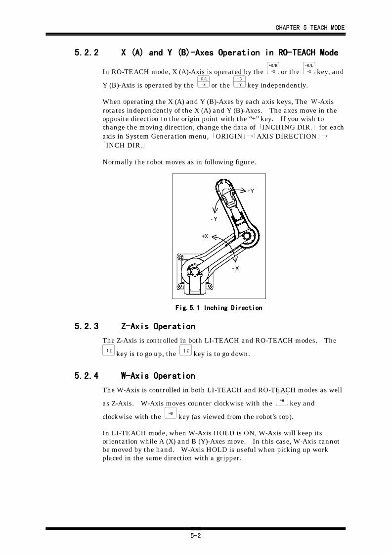
When operating the X (A) and Y (B)-Axes by each axis keys, The W-Axisrotates independently of the X (A) and Y (B)-Axes. The axes move in theopposite direction to the origin point with the “+” key. If you wish tochange the moving direction, change the data of 「INCHING DIR.」 for eachaxis in System Generation menu, 「ORIGIN」→「AXIS DIRECTION」→「INCH DIR.」
Normally the robot moves as in following figure.
-X
+X
-Y
+Y
Fig.Fig.Fig.Fig.5.5.5.5.1111 Inching Direction Inching Direction Inching Direction Inching Direction
5.2.35.2.35.2.35.2.3 Z-Axis OperationZ-Axis OperationZ-Axis OperationZ-Axis Operation
The Z-Axis is controlled in both LI-TEACH and RO-TEACH modes. The↑Z key is to go up, the ↓Z key is to go down.
5.2.45.2.45.2.45.2.4 W-Axis OperationW-Axis OperationW-Axis OperationW-Axis Operation
The W-Axis is controlled in both LI-TEACH and RO-TEACH modes as well
as Z-Axis. W-Axis moves counter clockwise with the +W key and
clockwise with the -W key (as viewed from the robot’s top).
In LI-TEACH mode, when W-Axis HOLD is ON, W-Axis will keep itsorientation while A (X) and B (Y)-Axes move. In this case, W-Axis cannotbe moved by the hand. W-Axis HOLD is useful when picking up workplaced in the same direction with a gripper.
CHAPTER 5 TEACH MODE
5-3
5.2.55.2.55.2.55.2.5 R-Axis Operation (Robot with 6 Axes)R-Axis Operation (Robot with 6 Axes)R-Axis Operation (Robot with 6 Axes)R-Axis Operation (Robot with 6 Axes)
The R-Axis is controlled in both LI-TEACH and RO-TEACH modes as well
as Z-Axis. Press the SHIFT
key to light up the 『SHIFT』 LED, then the R-
Axis moves counter clockwise with the +R/R
+X key and clockwise with the -R/L
-X
key (as viewed from the robot’s top).
5.2.65.2.65.2.65.2.6 C-Axis Operation (Robot with 6 Axes)C-Axis Operation (Robot with 6 Axes)C-Axis Operation (Robot with 6 Axes)C-Axis Operation (Robot with 6 Axes)
The C-Axis is controlled in both LI-TEACH and RO-TEACH modes as well
as Z-Axis. Press the SHIFT
key to light up the 『SHIFT』 LED, then the C-
Axis moves counter clockwise with the +C
+Y key and clockwise with the -C
-Y
key.
5.2.75.2.75.2.75.2.7 HOLD OperationHOLD OperationHOLD OperationHOLD Operation
Currently this function is not used in this system. HOLD is normally ON.
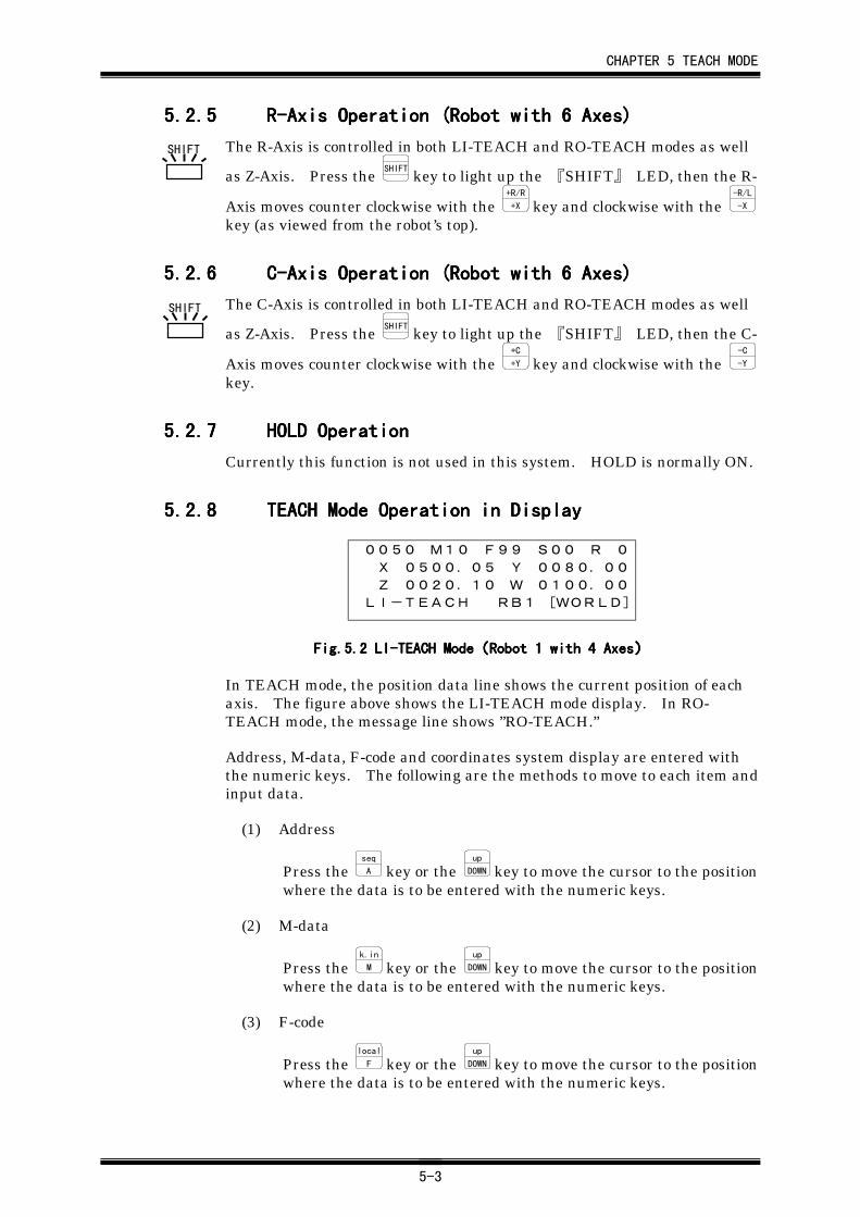
5.2.85.2.85.2.85.2.8 TEACH Mode Operation in DisplayTEACH Mode Operation in DisplayTEACH Mode Operation in DisplayTEACH Mode Operation in Display
0050 M10 F99 S00 R 0
X 0500.05 Y 0080.00
Z 0020.10 W 0100.00
LI-TEACH RB1 [WORLD]
Fig.Fig.Fig.Fig.5.5.5.5.2222 LI-TEACH Mode LI-TEACH Mode LI-TEACH Mode LI-TEACH Mode((((Robot 1 with 4 AxesRobot 1 with 4 AxesRobot 1 with 4 AxesRobot 1 with 4 Axes))))
In TEACH mode, the position data line shows the current position of eachaxis. The figure above shows the LI-TEACH mode display. In RO-TEACH mode, the message line shows ”RO-TEACH.”
Address, M-data, F-code and coordinates system display are entered withthe numeric keys. The following are the methods to move to each item andinput data.
(1) Address
Press the seq
A key or the up
DOWN key to move the cursor to the positionwhere the data is to be entered with the numeric keys.
(2) M-data
Press the k.in
M key or the up
DOWN key to move the cursor to the positionwhere the data is to be entered with the numeric keys.
(3) F-code
Press the local
F key or the up
DOWN key to move the cursor to the positionwhere the data is to be entered with the numeric keys.
SHIFT
SHIFT

CHAPTER 5 TEACH MODE
5-4
(4) S-code
Press the k.out
S key or the up
DOWN key to move the cursor to the positionwhere the data is to be entered with the numeric keys.
(5) Coordinates system display
Press the FUNC
HIGH+local
F keys or the up
DOWN key to move the cursor to theposition where the data is to be entered with the numeric keys.
5.2.95.2.95.2.95.2.9 Motion Speed in TEACH ModeMotion Speed in TEACH ModeMotion Speed in TEACH ModeMotion Speed in TEACH Mode
When you operate each axes using the axis keys on the Teach Pendant, the
axis moves at high speed by pressing each axis key with the FUNC
HIGH key.
To set the speed in TEACH mode, change the System Parameter i,「RESPONSE」→「RESPONSE」→「INCHING SPEED」 or pressing theSHIFT
+spd
CAN keys. When operating the axis with only the axis keys, the axesmove at the speed set by the 「INCHING SPEED」.
5.35.35.35.3 Speed Data Setting in TEACH ModeSpeed Data Setting in TEACH ModeSpeed Data Setting in TEACH ModeSpeed Data Setting in TEACH Mode
(1) Press the SHIFT
key in TEACH mode to light up the 『SHIFT』 LED,
then press the spd
CAN key to set the 「INCHING SPEED」 ii in SystemParameter menu.
(2) Enter the speed data.
(3) Press the spd
CAN key to return to the TEACH mode.
・ Entering the speed data sets the speed for all axes. Setting the speeddata for one axis is not possible.
・ The maximum speed in TEACH mode is 250 mm/sec.
i : Press the FUNC
HIGH+s.p
8 keys.ii : System Parameter, 「RESPONSE」→「RESPONSE」→「INCHING SPEED」
SHIFT
CHAPTER 5 TEACH MODE
5-5
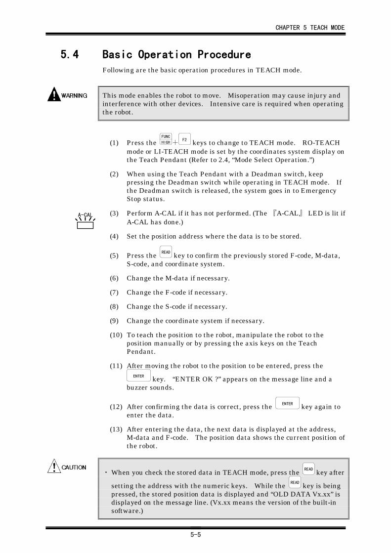
5.45.45.45.4 Basic Operation ProcedureBasic Operation ProcedureBasic Operation ProcedureBasic Operation ProcedureFollowing are the basic operation procedures in TEACH mode.
This mode enables the robot to move. Misoperation may cause injury andinterference with other devices. Intensive care is required when operatingthe robot.
(1) Press the FUNC
HIGH+F2 keys to change to TEACH mode. RO-TEACH
mode or LI-TEACH mode is set by the coordinates system display onthe Teach Pendant (Refer to 2.4, “Mode Select Operation.”)
(2) When using the Teach Pendant with a Deadman switch, keeppressing the Deadman switch while operating in TEACH mode. Ifthe Deadman switch is released, the system goes in to EmergencyStop status.
(3) Perform A-CAL if it has not performed. (The 『A-CAL』 LED is lit ifA-CAL has done.)
(4) Set the position address where the data is to be stored.
(5) Press the READ key to confirm the previously stored F-code, M-data,S-code, and coordinate system.
(6) Change the M-data if necessary.
(7) Change the F-code if necessary.
(8) Change the S-code if necessary.
(9) Change the coordinate system if necessary.
(10) To teach the position to the robot, manipulate the robot to theposition manually or by pressing the axis keys on the TeachPendant.
(11) After moving the robot to the position to be entered, press theENTER key. “ENTER OK ?” appears on the message line and a
buzzer sounds.
(12) After confirming the data is correct, press the ENTER key again toenter the data.
(13) After entering the data, the next data is displayed at the address,M-data and F-code. The position data shows the current position ofthe robot.
・ When you check the stored data in TEACH mode, press the READ key after
setting the address with the numeric keys. While the READ key is beingpressed, the stored position data is displayed and “OLD DATA Vx.xx” isdisplayed on the message line. (Vx.xx means the version of the built-insoftware.)
A-CAL
CHAPTER 5 TEACH MODE
5-6
・ If you press the ENTER key before completion of the A-CAL operation(when the A-CAL indicator is OFF) in step (10), “A-CALINCOMPLETE !!” is displayed on the message line and the data cannotbe entered. Perform A-CAL referring to Chapter 3, “A-CAL (AutomaticCalibration).”
A-CAL
CHAPTER 6 CHECK MODE
6-1
CHAPTER 6CHAPTER 6CHAPTER 6CHAPTER 6 CHECK ModeCHECK ModeCHECK ModeCHECK Mode
6.16.16.16.1 GeneralGeneralGeneralGeneralCHECK mode enables you to check the position data, which has beenentered in the KEY-IN or TEACH mode, by physically moving the robot.
Change the controller mode to MANUAL and press the FUNC
HIGH+F3 keys to
change to CHECK mode.
It is highly recommended to check the position data in CHECK mode beforeautomatic operation for the safety and to prevent the misprogramming ormalfunction of the robot.
While operating the robot in CHECK mode, hold a Deadman switch. If yourelease the Deadman switch, the system goes into Emergency Stop status.
6.26.26.26.2 FunctionsFunctionsFunctionsFunctions6.2.16.2.16.2.16.2.1 Positioning MethodPositioning MethodPositioning MethodPositioning Method
There are two methods, Point to Point (PTP) and Continuous Pass Control(CPC) movements. You can select the positioning method by the M-data inCHECK mode.
M=0 : No positioningM= 1-79 : PTP movementM=80-89 : CPC movementM=90-99 : PTP movement
Also, S-code affects the robot positioning method. Refer to Chapter 16,“Robot Operation.”
6.2.26.2.26.2.26.2.2 Speed SettingSpeed SettingSpeed SettingSpeed Setting
The speed can be set at 10 different levels, from 0 to 9. “0” is the minimumspeed and “9” is the maximum speed. At maximum speed “9” in CHECKmode, the robot moves at 250mm/sec for safety.
6.2.36.2.36.2.36.2.3 Auto Pull-Up FunctionAuto Pull-Up FunctionAuto Pull-Up FunctionAuto Pull-Up Function
If the Z-Axis is at a position lower than the pull up value in the SystemParameter i, 「MOTION」→「MOTION」→「PULL-UP」 (Refer to 19.1.1,“MOTION”), the Z-Axis will move upwards until the “pull-up” distance isreached. If the axis is at a position higher than the “pull-up” distance, theZ-Axis will not move.
This function prevents the robot from interfering with work and otherdevices. Note that the auto pull-up function is not valid at certain M-dataor S-code positions. Refer to Chapter 16, “Robot Operation” for details.
i: Press the FUNC
HIGH+s.p
8 keys.
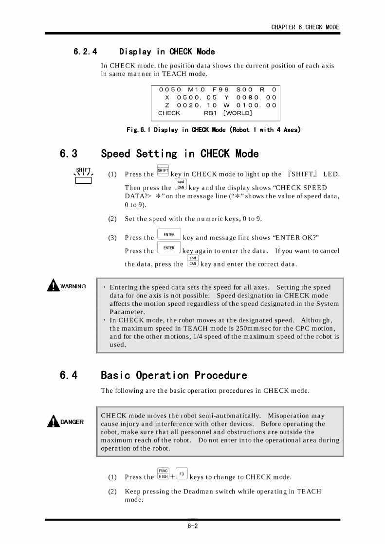
CHAPTER 6 CHECK MODE
6-2
6.2.46.2.46.2.46.2.4 Display in CHECK ModeDisplay in CHECK ModeDisplay in CHECK ModeDisplay in CHECK Mode
In CHECK mode, the position data shows the current position of each axisin same manner in TEACH mode.
0050 M10 F99 S00 R 0
X 0500.05 Y 0080.00
Z 0020.10 W 0100.00
CHECK RB1 [WORLD]
Fig.Fig.Fig.Fig.6.6.6.6.1111 Display in CHECK Mode Display in CHECK Mode Display in CHECK Mode Display in CHECK Mode((((Robot 1 with 4 AxesRobot 1 with 4 AxesRobot 1 with 4 AxesRobot 1 with 4 Axes))))
6.36.36.36.3 Speed Setting in CHECK ModeSpeed Setting in CHECK ModeSpeed Setting in CHECK ModeSpeed Setting in CHECK Mode
(1) Press the SHIFT
key in CHECK mode to light up the 『SHIFT』 LED.
Then press the spd
CAN key and the display shows “CHECK SPEEDDATA?> *” on the message line (“*” shows the value of speed data,0 to 9).
(2) Set the speed with the numeric keys, 0 to 9.
(3) Press the ENTER key and message line shows “ENTER OK?”
Press the ENTER key again to enter the data. If you want to cancel
the data, press the spd
CAN key and enter the correct data.
・ Entering the speed data sets the speed for all axes. Setting the speeddata for one axis is not possible. Speed designation in CHECK modeaffects the motion speed regardless of the speed designated in the SystemParameter.
・ In CHECK mode, the robot moves at the designated speed. Although,the maximum speed in TEACH mode is 250mm/sec for the CPC motion,and for the other motions, 1/4 speed of the maximum speed of the robot isused.
6.46.46.46.4 Basic Operation ProcedureBasic Operation ProcedureBasic Operation ProcedureBasic Operation ProcedureThe following are the basic operation procedures in CHECK mode.
CHECK mode moves the robot semi-automatically. Misoperation maycause injury and interference with other devices. Before operating therobot, make sure that all personnel and obstructions are outside themaximum reach of the robot. Do not enter into the operational area duringoperation of the robot.
(1) Press the FUNC
HIGH+F3 keys to change to CHECK mode.
(2) Keep pressing the Deadman switch while operating in TEACHmode.
SHIFT
CHAPTER 6 CHECK MODE
6-3
(3) Perform A-CAL . It is not necessary to perform A-CAL if it iscompleted or the 『A-CAL』 LED is OFF.
(4) Set the speed in CHECK mode.
(5) Enter the address which you wish to confirm the position.
Enter the address with the numeric keys and press the READ key.
(6) After setting the address, press the START key. While pressing theSTART key, the robot moves to the position which is specified by the
address. If the START key is released or an error occurred, themessage line shows “INCOMPLETE” and the robot stops.
After the positioning is done successfully, ”COMPLETED”appearson the message line and a buzzer sounds. To continue the
positioning to the next address, release the START key and keep
pressing the START key again until the positioning is done.
When the 『SHIFT』 LED is lit during the CPC or the Pass PTPmotion, the positioning is completed every time an arc or a straight
line ends. Release and press the START key to position to the nextaddress (Refer to 16.3.1, “Notes on CPC Operation”).
・ In CHECK mode, normally the current position data of the robot is
displayed. To check the stored position data, press the READ key after
setting the address data with the numeric keys. While the READ key isbeing pressed, the stored position data is displayed and “OLD DATAVx.xx” is displayed on the message line (Vx.xx means the version of thebuilt-in software.).
・ If you press the START key before completion of the A-CAL operation (whenthe 『A-CAL』 LED is OFF), “A-CAL INCOMPLETE !!” is displayed onthe message line and the data cannot be entered. Perform A-CALreferring to Chapter 3, “A-CAL (Automatic Calibration).”
・ The positioning method of the robot is affected by M-data or S-code.Refer to 16.4.1, “List of M-Data Functions” and 16.4.2, “List of S-CodeFunctions” for details.
A-CAL
A-CAL
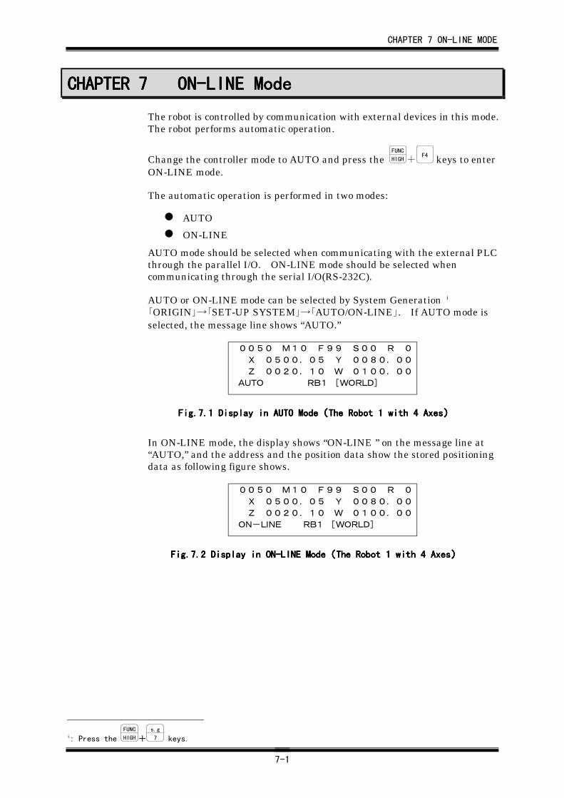
CHAPTER 7 ON-LINE MODE
7-1
CHAPTER 7CHAPTER 7CHAPTER 7CHAPTER 7 ON-LINE ModeON-LINE ModeON-LINE ModeON-LINE Mode
The robot is controlled by communication with external devices in this mode.The robot performs automatic operation.
Change the controller mode to AUTO and press the FUNC
HIGH+F4 keys to enter
ON-LINE mode.
The automatic operation is performed in two modes:
AUTO
ON-LINE
AUTO mode should be selected when communicating with the external PLCthrough the parallel I/O. ON-LINE mode should be selected whencommunicating through the serial I/O(RS-232C).
AUTO or ON-LINE mode can be selected by System Generation i
「ORIGIN」→「SET-UP SYSTEM」→「AUTO/ON-LINE」. If AUTO mode isselected, the message line shows “AUTO.”
0050 M10 F99 S00 R 0
X 0500.05 Y 0080.00
Z 0020.10 W 0100.00
AUTO RB1 [WORLD]
Fig.7.Fig.7.Fig.7.Fig.7.1111 Display in AUTO Mode Display in AUTO Mode Display in AUTO Mode Display in AUTO Mode((((The Robot 1 with 4 AxesThe Robot 1 with 4 AxesThe Robot 1 with 4 AxesThe Robot 1 with 4 Axes))))
In ON-LINE mode, the display shows “ON-LINE ” on the message line at“AUTO,” and the address and the position data show the stored positioningdata as following figure shows.
0050 M10 F99 S00 R 0
X 0500.05 Y 0080.00
Z 0020.10 W 0100.00
ON-LINE RB1 [WORLD]
Fig.7.Fig.7.Fig.7.Fig.7.2222 Display in ON-LINE Mode Display in ON-LINE Mode Display in ON-LINE Mode Display in ON-LINE Mode((((The Robot 1 with 4 AxesThe Robot 1 with 4 AxesThe Robot 1 with 4 AxesThe Robot 1 with 4 Axes))))
i: Press the FUNC
HIGH+s.g
7 keys.
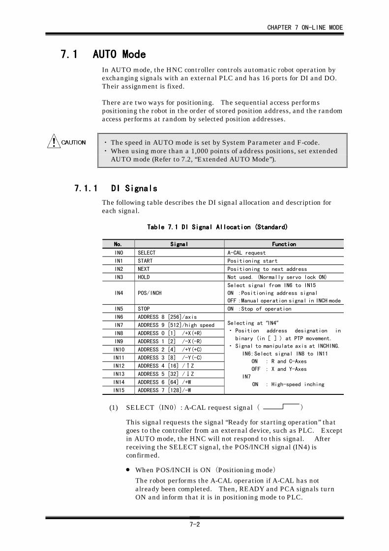
CHAPTER 7 ON-LINE MODE
7-2
7.17.17.17.1 AUTO ModeAUTO ModeAUTO ModeAUTO ModeIn AUTO mode, the HNC controller controls automatic robot operation byexchanging signals with an external PLC and has 16 ports for DI and DO.Their assignment is fixed.
There are two ways for positioning. The sequential access performspositioning the robot in the order of stored position address, and the randomaccess performs at random by selected position addresses.
・ The speed in AUTO mode is set by System Parameter and F-code.・ When using more than a 1,000 points of address positions, set extended
AUTO mode (Refer to 7.2, “Extended AUTO Mode”).
7.1.17.1.17.1.17.1.1 DI SignalsDI SignalsDI SignalsDI Signals
The following table describes the DI signal allocation and description foreach signal.
Table 7.Table 7.Table 7.Table 7.1111 DI Signal Allocation (Standard) DI Signal Allocation (Standard) DI Signal Allocation (Standard) DI Signal Allocation (Standard)
No.No.No.No. SignalSignalSignalSignal FunctionFunctionFunctionFunction
IN0 SELECT A-CAL request
IN1 START Positioning start
IN2 NEXT Positioning to next address
IN3 HOLD Not used. (Normally servo lock ON)
IN4 POS/INCH
Select signal from IN6 to IN15
ON :Positioning address signal
OFF :Manual operation signal in INCH mode
IN5 STOP ON :Stop of operation
IN6 ADDRESS 8 [256]/axis
IN7 ADDRESS 9 [512]/high speed
IN8 ADDRESS 0 [1] /+X(+R)
IN9 ADDRESS 1 [2] /-X(-R)
IN10 ADDRESS 2 [4] /+Y(+C)
IN11 ADDRESS 3 [8] /-Y(-C)
IN12 ADDRESS 4 [16] /↑Z
IN13 ADDRESS 5 [32] /↓Z
IN14 ADDRESS 6 [64] /+W
IN15 ADDRESS 7 [128]/-W
Selecting at “IN4”・ Position address designation in
binary (in[ ]) at PTP movement.
・ Signal to manipulate axis at INCHING.
IN6:Select signal IN8 to IN11
ON : R and C-Axes
OFF : X and Y-Axes
IN7
ON : High-speed inching
(1) SELECT(IN0): A-CAL request signal( )
This signal requests the signal “Ready for starting operation” thatgoes to the controller from an external device, such as PLC. Exceptin AUTO mode, the HNC will not respond to this signal. Afterreceiving the SELECT signal, the POS/INCH signal (IN4) isconfirmed.
• When POS/INCH is ON(Positioning mode)
The robot performs the A-CAL operation if A-CAL has notalready been completed. Then, READY and PCA signals turnON and inform that it is in positioning mode to PLC.
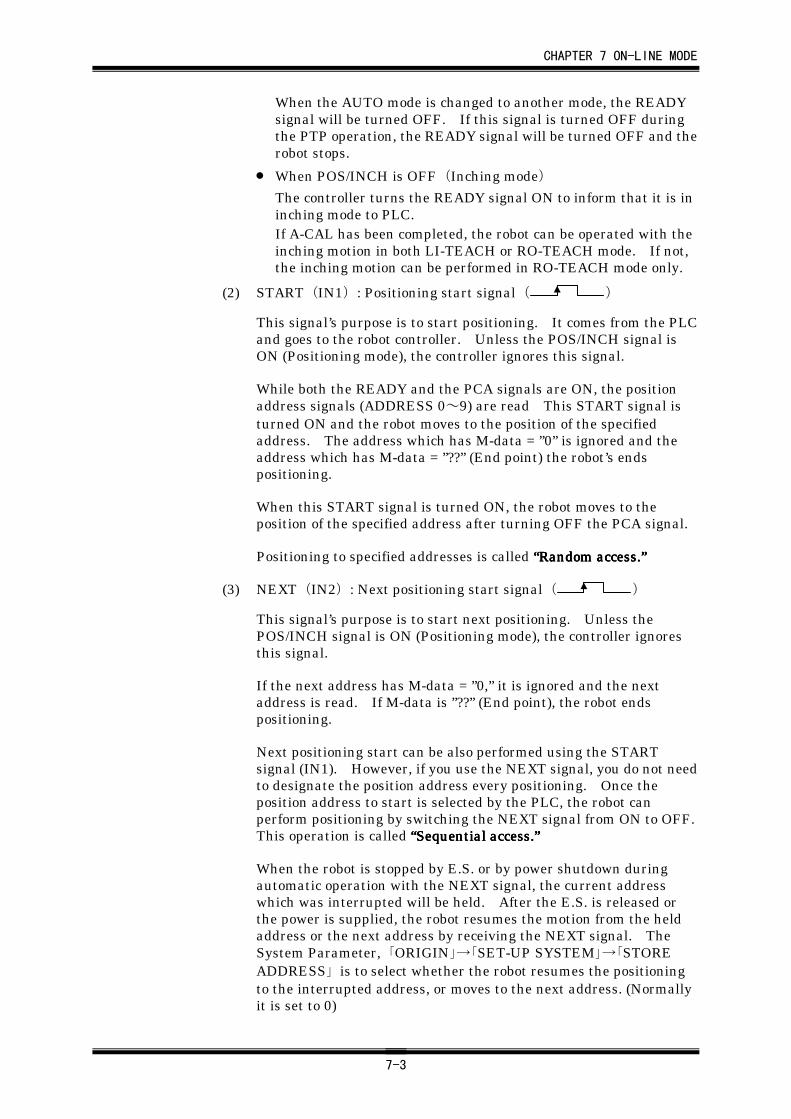
CHAPTER 7 ON-LINE MODE
7-3
When the AUTO mode is changed to another mode, the READYsignal will be turned OFF. If this signal is turned OFF duringthe PTP operation, the READY signal will be turned OFF and therobot stops.
• When POS/INCH is OFF(Inching mode)
The controller turns the READY signal ON to inform that it is ininching mode to PLC.If A-CAL has been completed, the robot can be operated with theinching motion in both LI-TEACH or RO-TEACH mode. If not,the inching motion can be performed in RO-TEACH mode only.
(2) START(IN1): Positioning start signal( )
This signal’s purpose is to start positioning. It comes from the PLCand goes to the robot controller. Unless the POS/INCH signal isON (Positioning mode), the controller ignores this signal.
While both the READY and the PCA signals are ON, the positionaddress signals (ADDRESS 0~9) are read This START signal isturned ON and the robot moves to the position of the specifiedaddress. The address which has M-data = ”0” is ignored and theaddress which has M-data = ”??” (End point) the robot’s endspositioning.
When this START signal is turned ON, the robot moves to theposition of the specified address after turning OFF the PCA signal.
Positioning to specified addresses is called ““““Random access.Random access.Random access.Random access.””””
(3) NEXT(IN2): Next positioning start signal( )
This signal’s purpose is to start next positioning. Unless thePOS/INCH signal is ON (Positioning mode), the controller ignoresthis signal.
If the next address has M-data = ”0,” it is ignored and the nextaddress is read. If M-data is ”??” (End point), the robot endspositioning.
Next positioning start can be also performed using the STARTsignal (IN1). However, if you use the NEXT signal, you do not needto designate the position address every positioning. Once theposition address to start is selected by the PLC, the robot canperform positioning by switching the NEXT signal from ON to OFF.This operation is called ““““Sequential access.Sequential access.Sequential access.Sequential access.””””
When the robot is stopped by E.S. or by power shutdown duringautomatic operation with the NEXT signal, the current addresswhich was interrupted will be held. After the E.S. is released orthe power is supplied, the robot resumes the motion from the heldaddress or the next address by receiving the NEXT signal. TheSystem Parameter, 「ORIGIN」→「SET-UP SYSTEM」→「STOREADDRESS」 is to select whether the robot resumes the positioningto the interrupted address, or moves to the next address. (Normallyit is set to 0)
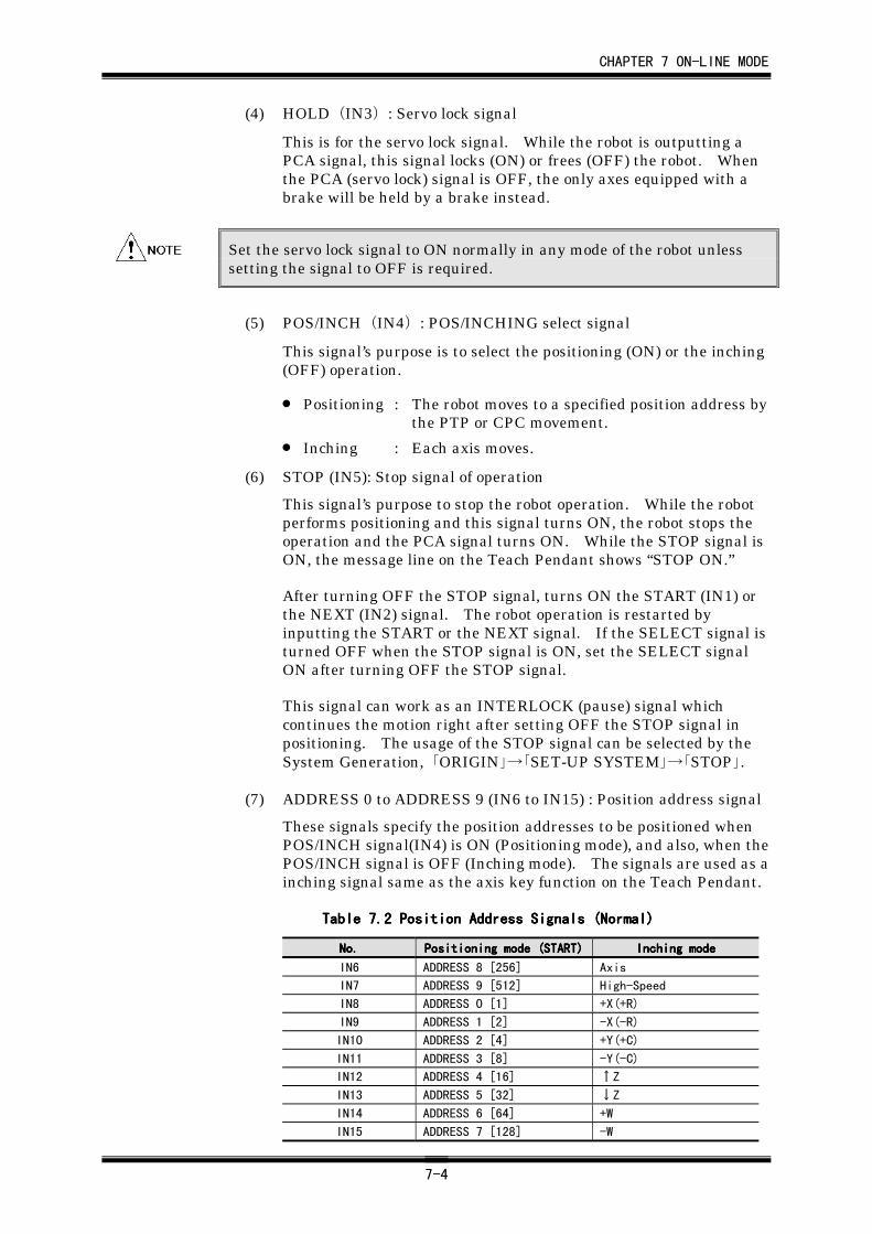
CHAPTER 7 ON-LINE MODE
7-4
(4) HOLD(IN3): Servo lock signal
This is for the servo lock signal. While the robot is outputting aPCA signal, this signal locks (ON) or frees (OFF) the robot. Whenthe PCA (servo lock) signal is OFF, the only axes equipped with abrake will be held by a brake instead.
Set the servo lock signal to ON normally in any mode of the robot unlesssetting the signal to OFF is required.
(5) POS/INCH(IN4): POS/INCHING select signal
This signal’s purpose is to select the positioning (ON) or the inching(OFF) operation.
• Positioning : The robot moves to a specified position address bythe PTP or CPC movement.
• Inching : Each axis moves.
(6) STOP (IN5): Stop signal of operation
This signal’s purpose to stop the robot operation. While the robotperforms positioning and this signal turns ON, the robot stops theoperation and the PCA signal turns ON. While the STOP signal isON, the message line on the Teach Pendant shows “STOP ON.”
After turning OFF the STOP signal, turns ON the START (IN1) orthe NEXT (IN2) signal. The robot operation is restarted byinputting the START or the NEXT signal. If the SELECT signal isturned OFF when the STOP signal is ON, set the SELECT signalON after turning OFF the STOP signal.
This signal can work as an INTERLOCK (pause) signal whichcontinues the motion right after setting OFF the STOP signal inpositioning. The usage of the STOP signal can be selected by theSystem Generation, 「ORIGIN」→「SET-UP SYSTEM」→「STOP」.
(7) ADDRESS 0 to ADDRESS 9 (IN6 to IN15) : Position address signal
These signals specify the position addresses to be positioned whenPOS/INCH signal(IN4) is ON (Positioning mode), and also, when thePOS/INCH signal is OFF (Inching mode). The signals are used as ainching signal same as the axis key function on the Teach Pendant.
Table 7.Table 7.Table 7.Table 7.2222 Position Address Signals (Normal) Position Address Signals (Normal) Position Address Signals (Normal) Position Address Signals (Normal)
No.No.No.No. Positioning mode (START)Positioning mode (START)Positioning mode (START)Positioning mode (START) Inching modeInching modeInching modeInching mode
IN6 ADDRESS 8 [256] Axis
IN7 ADDRESS 9 [512] High-Speed
IN8 ADDRESS 0 [1] +X(+R)
IN9 ADDRESS 1 [2] -X(-R)
IN10 ADDRESS 2 [4] +Y(+C)
IN11 ADDRESS 3 [8] -Y(-C)
IN12 ADDRESS 4 [16] ↑Z
IN13 ADDRESS 5 [32] ↓Z
IN14 ADDRESS 6 [64] +W
IN15 ADDRESS 7 [128] -W
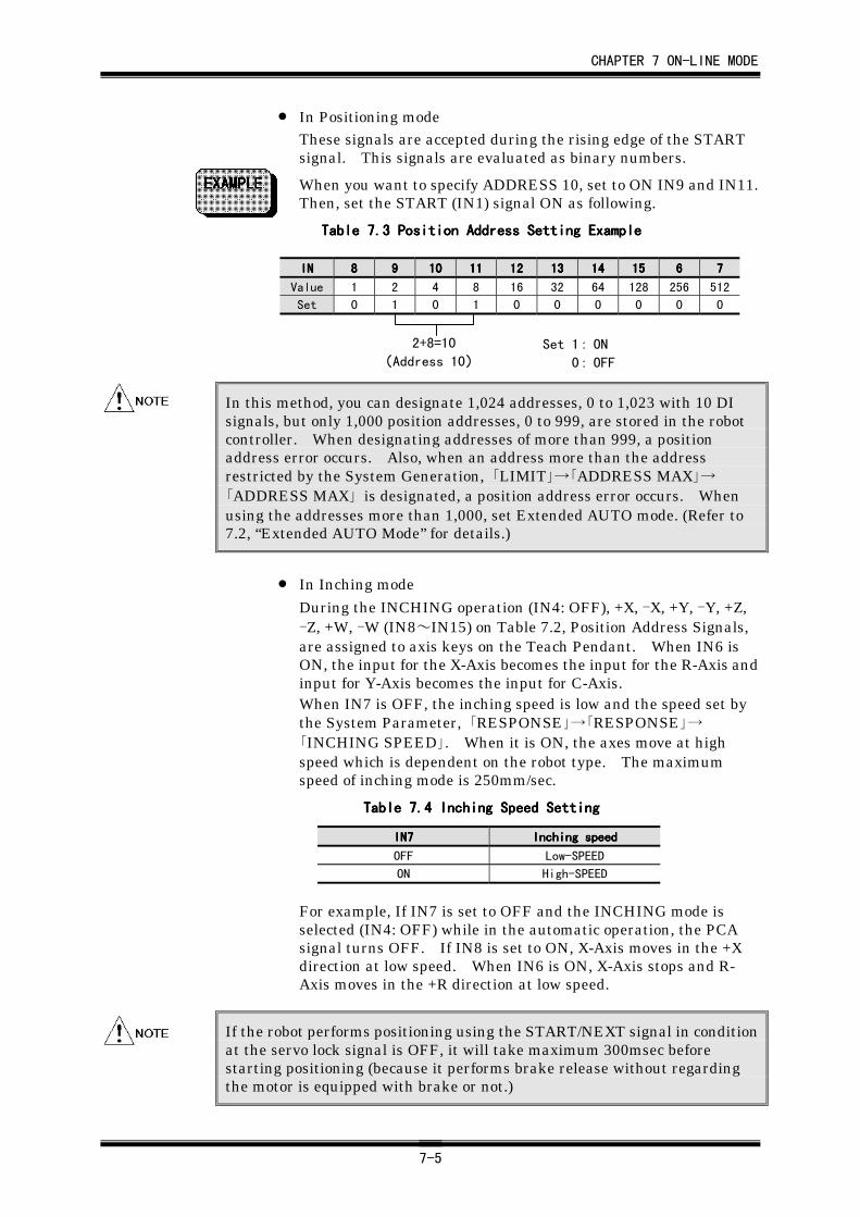
CHAPTER 7 ON-LINE MODE
7-5
• In Positioning modeThese signals are accepted during the rising edge of the STARTsignal. This signals are evaluated as binary numbers.
When you want to specify ADDRESS 10, set to ON IN9 and IN11.Then, set the START (IN1) signal ON as following.
Table 7.Table 7.Table 7.Table 7.3333 Position Address Setting Example Position Address Setting Example Position Address Setting Example Position Address Setting Example
ININININ 8888 9999 10101010 11111111 12121212 13131313 14141414 15151515 6666 7777
Value 1 2 4 8 16 32 64 128 256 512
Set 0 1 0 1 0 0 0 0 0 0
In this method, you can designate 1,024 addresses, 0 to 1,023 with 10 DIsignals, but only 1,000 position addresses, 0 to 999, are stored in the robotcontroller. When designating addresses of more than 999, a positionaddress error occurs. Also, when an address more than the addressrestricted by the System Generation, 「LIMIT」→「ADDRESS MAX」→「ADDRESS MAX」 is designated, a position address error occurs. Whenusing the addresses more than 1,000, set Extended AUTO mode. (Refer to7.2, “Extended AUTO Mode” for details.)
• In Inching mode
During the INCHING operation (IN4: OFF), +X, -X, +Y, -Y, +Z,-Z, +W, -W (IN8~IN15) on Table 7.2, Position Address Signals,are assigned to axis keys on the Teach Pendant. When IN6 isON, the input for the X-Axis becomes the input for the R-Axis andinput for Y-Axis becomes the input for C-Axis.When IN7 is OFF, the inching speed is low and the speed set bythe System Parameter, 「RESPONSE」→「RESPONSE」→「INCHING SPEED」. When it is ON, the axes move at highspeed which is dependent on the robot type. The maximumspeed of inching mode is 250mm/sec.
Table 7.Table 7.Table 7.Table 7.4444 Inching Speed Setting Inching Speed Setting Inching Speed Setting Inching Speed Setting
IN7IN7IN7IN7 Inching speedInching speedInching speedInching speed
OFF Low-SPEED
ON High-SPEED
For example, If IN7 is set to OFF and the INCHING mode isselected (IN4: OFF) while in the automatic operation, the PCAsignal turns OFF. If IN8 is set to ON, X-Axis moves in the +Xdirection at low speed. When IN6 is ON, X-Axis stops and R-Axis moves in the +R direction at low speed.
If the robot performs positioning using the START/NEXT signal in conditionat the servo lock signal is OFF, it will take maximum 300msec beforestarting positioning (because it performs brake release without regardingthe motor is equipped with brake or not.)
2+8=10
(Address 10)Set 1: ON
0: OFF
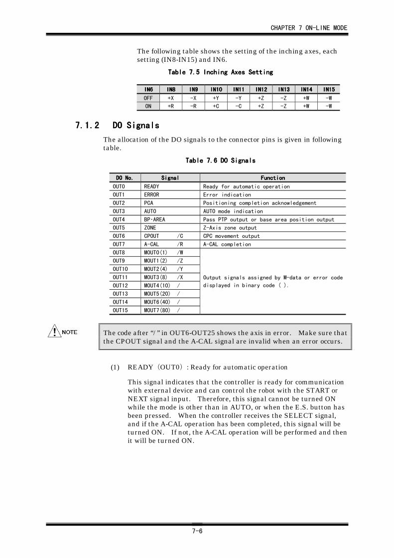
CHAPTER 7 ON-LINE MODE
7-6
The following table shows the setting of the inching axes, eachsetting (IN8-IN15) and IN6.
Table 7.Table 7.Table 7.Table 7.5555 Inching Axes Setting Inching Axes Setting Inching Axes Setting Inching Axes Setting
IN6IN6IN6IN6 IN8IN8IN8IN8 IN9IN9IN9IN9 IN10IN10IN10IN10 IN11IN11IN11IN11 IN12IN12IN12IN12 IN13IN13IN13IN13 IN14IN14IN14IN14 IN15IN15IN15IN15
OFF +X -X +Y -Y +Z -Z +W -W
ON +R -R +C -C +Z -Z +W -W
7.1.27.1.27.1.27.1.2 DO SignalsDO SignalsDO SignalsDO Signals
The allocation of the DO signals to the connector pins is given in followingtable.
Table 7.Table 7.Table 7.Table 7.6666 DO Signals DO Signals DO Signals DO Signals
DO No.DO No.DO No.DO No. SignalSignalSignalSignal FunctionFunctionFunctionFunction
OUT0 READY Ready for automatic operation
OUT1 ERROR Error indication
OUT2 PCA Positioning completion acknowledgement
OUT3 AUTO AUTO mode indication
OUT4 BP・AREA Pass PTP output or base area position output
OUT5 ZONE Z-Axis zone output
OUT6 CPOUT /C CPC movement output
OUT7 A-CAL /R A-CAL completion
OUT8 MOUT0(1) /W
OUT9 MOUT1(2) /Z
OUT10 MOUT2(4) /Y
OUT11 MOUT3(8) /X
OUT12 MOUT4(10) /
OUT13 MOUT5(20) /
OUT14 MOUT6(40) /
OUT15 MOUT7(80) /
Output signals assigned by M-data or error code
displayed in binary code ( ).
The code after “/ ” in OUT6-OUT25 shows the axis in error. Make sure thatthe CPOUT signal and the A-CAL signal are invalid when an error occurs.
(1) READY(OUT0): Ready for automatic operation
This signal indicates that the controller is ready for communicationwith external device and can control the robot with the START orNEXT signal input. Therefore, this signal cannot be turned ONwhile the mode is other than in AUTO, or when the E.S. button hasbeen pressed. When the controller receives the SELECT signal,and if the A-CAL operation has been completed, this signal will beturned ON. If not, the A-CAL operation will be performed and thenit will be turned ON.
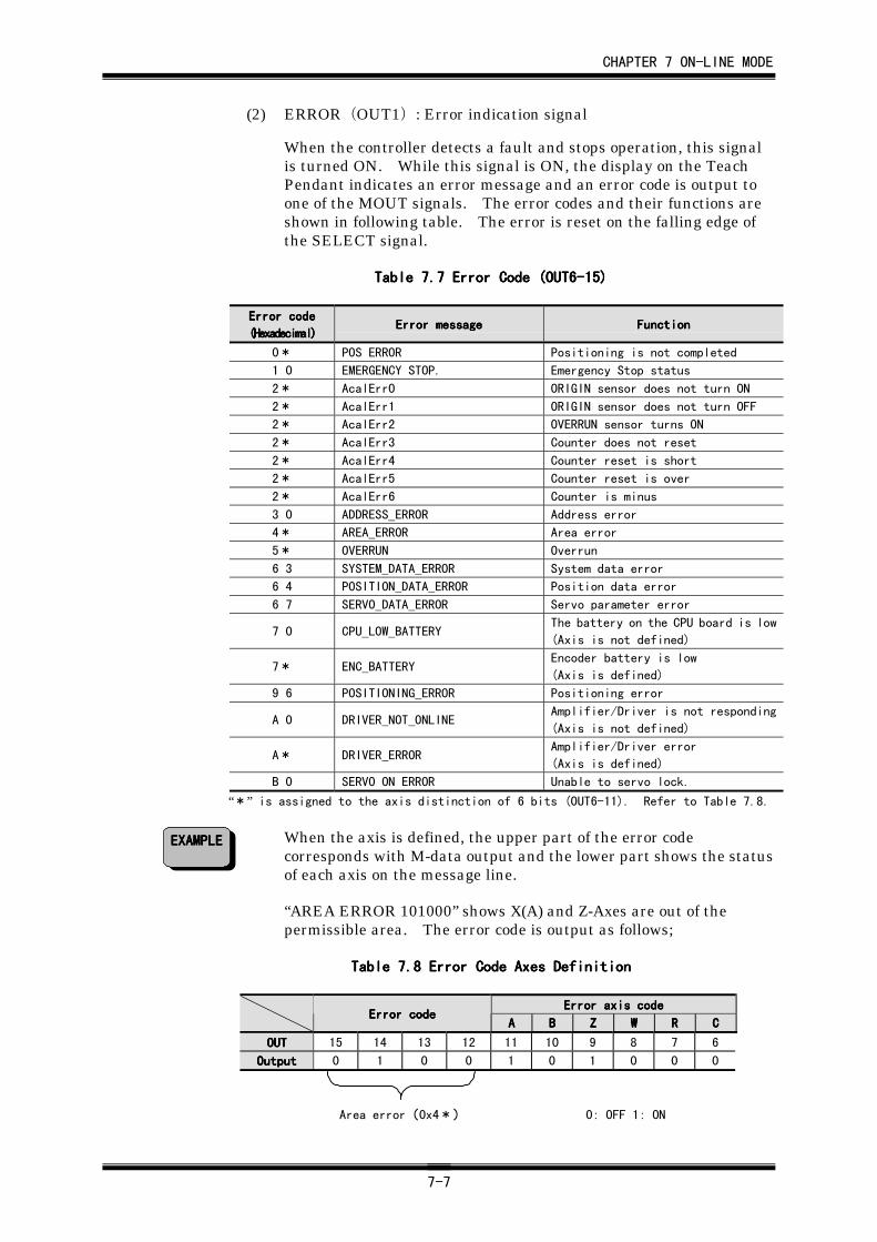
CHAPTER 7 ON-LINE MODE
7-7
(2) ERROR(OUT1): Error indication signal
When the controller detects a fault and stops operation, this signalis turned ON. While this signal is ON, the display on the TeachPendant indicates an error message and an error code is output toone of the MOUT signals. The error codes and their functions areshown in following table. The error is reset on the falling edge ofthe SELECT signal.
Table 7.Table 7.Table 7.Table 7.7777 Error Code (OUT6-15) Error Code (OUT6-15) Error Code (OUT6-15) Error Code (OUT6-15)
Error codeError codeError codeError code
(Hexadecimal)(Hexadecimal)(Hexadecimal)(Hexadecimal)Error messageError messageError messageError message FunctionFunctionFunctionFunction
0* POS ERROR Positioning is not completed
1 0 EMERGENCY STOP. Emergency Stop status
2* AcalErr0 ORIGIN sensor does not turn ON
2* AcalErr1 ORIGIN sensor does not turn OFF
2* AcalErr2 OVERRUN sensor turns ON
2* AcalErr3 Counter does not reset
2* AcalErr4 Counter reset is short
2* AcalErr5 Counter reset is over
2* AcalErr6 Counter is minus
3 0 ADDRESS_ERROR Address error
4* AREA_ERROR Area error
5* OVERRUN Overrun
6 3 SYSTEM_DATA_ERROR System data error
6 4 POSITION_DATA_ERROR Position data error
6 7 SERVO_DATA_ERROR Servo parameter error
7 0 CPU_LOW_BATTERYThe battery on the CPU board is low
(Axis is not defined)
7* ENC_BATTERYEncoder battery is low
(Axis is defined)
9 6 POSITIONING_ERROR Positioning error
A 0 DRIVER_NOT_ONLINEAmplifier/Driver is not responding
(Axis is not defined)
A* DRIVER_ERRORAmplifier/Driver error
(Axis is defined)
B 0 SERVO ON ERROR Unable to servo lock.
“*” is assigned to the axis distinction of 6 bits (OUT6-11). Refer to Table 7.8.
When the axis is defined, the upper part of the error codecorresponds with M-data output and the lower part shows the statusof each axis on the message line.
“AREA ERROR 101000” shows X(A) and Z-Axes are out of thepermissible area. The error code is output as follows;
Table 7.Table 7.Table 7.Table 7.8888 Error Code Axes Definition Error Code Axes Definition Error Code Axes Definition Error Code Axes Definition
Error axis codeError axis codeError axis codeError axis codeError codeError codeError codeError code
AAAA BBBB ZZZZ WWWW RRRR CCCC
OUTOUTOUTOUT 15 14 13 12 11 10 9 8 7 6
OutputOutputOutputOutput 0 1 0 0 1 0 1 0 0 0
Area error(0x4*) 0: OFF 1: ON
EXAMPLEEXAMPLEEXAMPLEEXAMPLE
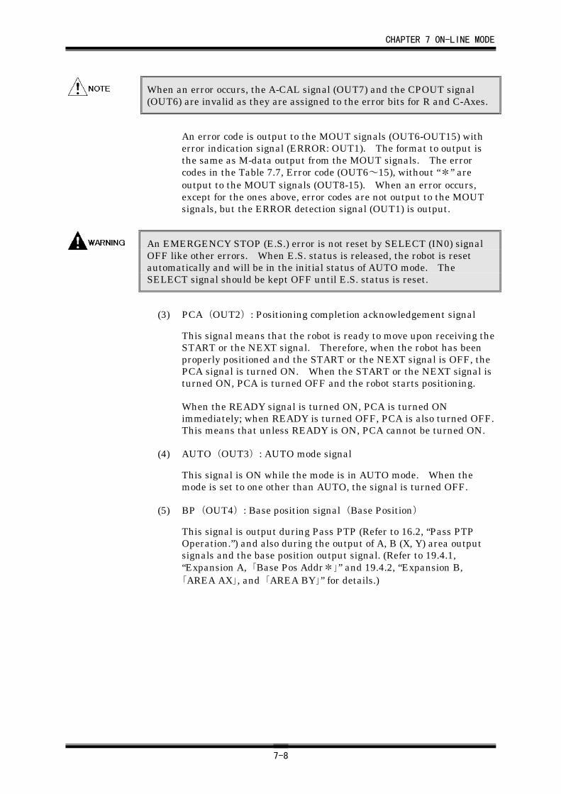
CHAPTER 7 ON-LINE MODE
7-8
When an error occurs, the A-CAL signal (OUT7) and the CPOUT signal(OUT6) are invalid as they are assigned to the error bits for R and C-Axes.
An error code is output to the MOUT signals (OUT6-OUT15) witherror indication signal (ERROR: OUT1). The format to output isthe same as M-data output from the MOUT signals. The errorcodes in the Table 7.7, Error code (OUT6~15), without “*” areoutput to the MOUT signals (OUT8-15). When an error occurs,except for the ones above, error codes are not output to the MOUTsignals, but the ERROR detection signal (OUT1) is output.
An EMERGENCY STOP (E.S.) error is not reset by SELECT (IN0) signalOFF like other errors. When E.S. status is released, the robot is resetautomatically and will be in the initial status of AUTO mode. TheSELECT signal should be kept OFF until E.S. status is reset.
(3) PCA(OUT2): Positioning completion acknowledgement signal
This signal means that the robot is ready to move upon receiving theSTART or the NEXT signal. Therefore, when the robot has beenproperly positioned and the START or the NEXT signal is OFF, thePCA signal is turned ON. When the START or the NEXT signal isturned ON, PCA is turned OFF and the robot starts positioning.
When the READY signal is turned ON, PCA is turned ONimmediately; when READY is turned OFF, PCA is also turned OFF.This means that unless READY is ON, PCA cannot be turned ON.
(4) AUTO(OUT3): AUTO mode signal
This signal is ON while the mode is in AUTO mode. When themode is set to one other than AUTO, the signal is turned OFF.
(5) BP(OUT4): Base position signal(Base Position)
This signal is output during Pass PTP (Refer to 16.2, “Pass PTPOperation.”) and also during the output of A, B (X, Y) area outputsignals and the base position output signal. (Refer to 19.4.1,“Expansion A, 「Base Pos Addr*」” and 19.4.2, “Expansion B,「AREA AX」, and 「AREA BY」” for details.)
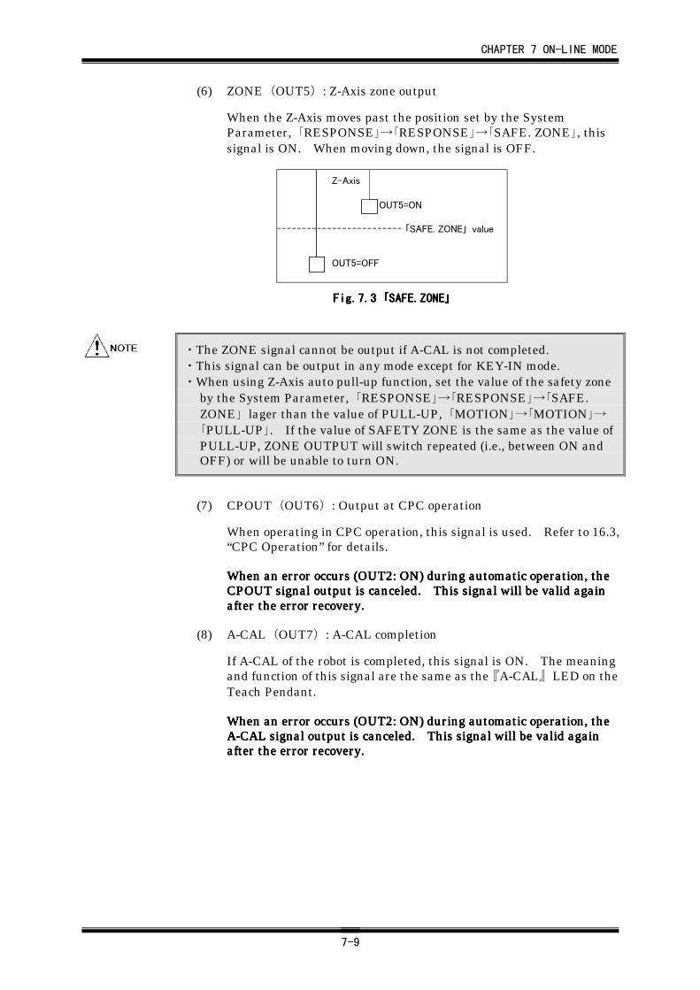
CHAPTER 7 ON-LINE MODE
7-9
(6) ZONE(OUT5): Z-Axis zone output
When the Z-Axis moves past the position set by the SystemParameter, 「RESPONSE」→「RESPONSE」→「SAFE. ZONE」, thissignal is ON. When moving down, the signal is OFF.
「SAFE. ZONE」 value
OUT5=ON
OUT5=OFF
Z-Axis
Fig.7.Fig.7.Fig.7.Fig.7.3333 「「「「SAFE.ZONESAFE.ZONESAFE.ZONESAFE.ZONE」」」」
・The ZONE signal cannot be output if A-CAL is not completed.・This signal can be output in any mode except for KEY-IN mode.・When using Z-Axis auto pull-up function, set the value of the safety zone
by the System Parameter, 「RESPONSE」→「RESPONSE」→「SAFE.ZONE」 lager than the value of PULL-UP, 「MOTION」→「MOTION」→「PULL-UP」. If the value of SAFETY ZONE is the same as the value ofPULL-UP, ZONE OUTPUT will switch repeated (i.e., between ON andOFF) or will be unable to turn ON.
(7) CPOUT(OUT6): Output at CPC operation
When operating in CPC operation, this signal is used. Refer to 16.3,“CPC Operation” for details.
When an error occurs (OUT2: ON) during automatic operation, theWhen an error occurs (OUT2: ON) during automatic operation, theWhen an error occurs (OUT2: ON) during automatic operation, theWhen an error occurs (OUT2: ON) during automatic operation, theCPOUT signal output is canceled. This signal will be valid againCPOUT signal output is canceled. This signal will be valid againCPOUT signal output is canceled. This signal will be valid againCPOUT signal output is canceled. This signal will be valid againafter the error recovery.after the error recovery.after the error recovery.after the error recovery.
(8) A-CAL(OUT7): A-CAL completion
If A-CAL of the robot is completed, this signal is ON. The meaningand function of this signal are the same as the 『A-CAL』 LED on theTeach Pendant.
When an error occurs (OUT2: ON) during automatic operation, theWhen an error occurs (OUT2: ON) during automatic operation, theWhen an error occurs (OUT2: ON) during automatic operation, theWhen an error occurs (OUT2: ON) during automatic operation, theA-CAL signal output is canceled. This signal will be valid againA-CAL signal output is canceled. This signal will be valid againA-CAL signal output is canceled. This signal will be valid againA-CAL signal output is canceled. This signal will be valid againafter after after after thethethethe error recovery. error recovery. error recovery. error recovery.
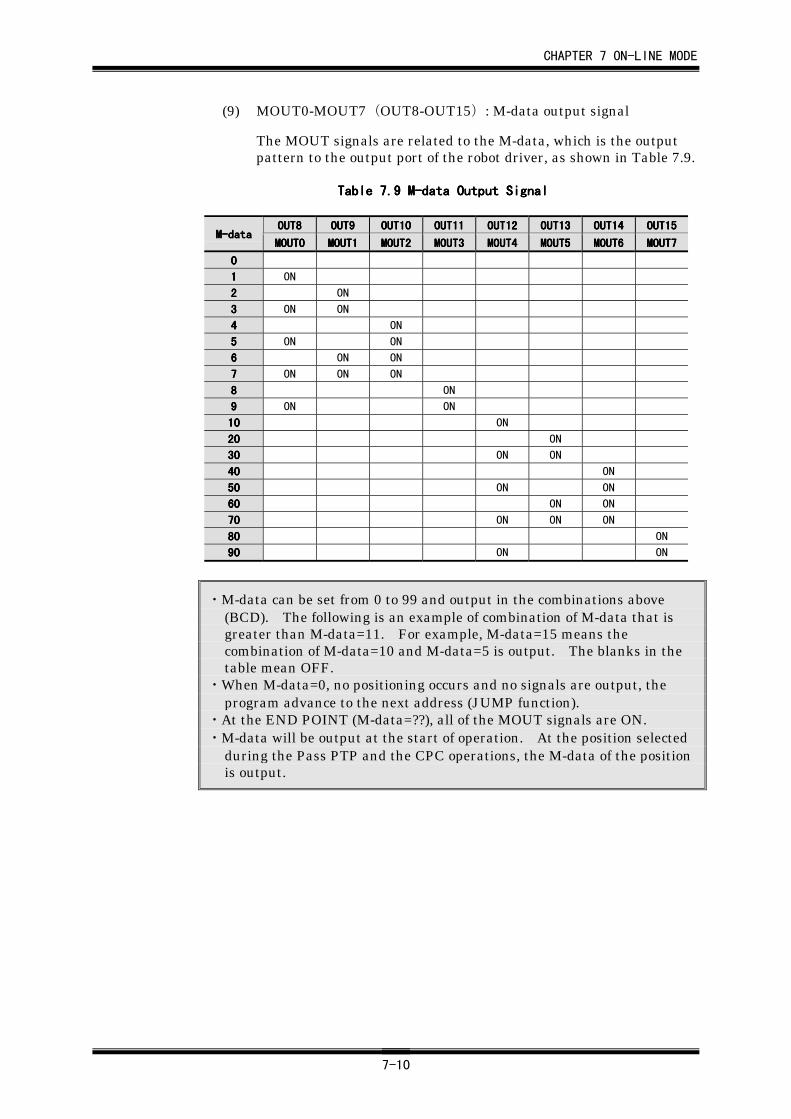
CHAPTER 7 ON-LINE MODE
7-10
(9) MOUT0-MOUT7(OUT8-OUT15): M-data output signal
The MOUT signals are related to the M-data, which is the outputpattern to the output port of the robot driver, as shown in Table 7.9.
Table 7.Table 7.Table 7.Table 7.9999 M-data Output Signal M-data Output Signal M-data Output Signal M-data Output Signal
OUT8OUT8OUT8OUT8 OUTOUTOUTOUT9999 OUT10OUT10OUT10OUT10 OUT11OUT11OUT11OUT11 OUT12OUT12OUT12OUT12 OUT13OUT13OUT13OUT13 OUT14OUT14OUT14OUT14 OUT15OUT15OUT15OUT15M-dataM-dataM-dataM-data
MOUT0MOUT0MOUT0MOUT0 MOUT1MOUT1MOUT1MOUT1 MOUT2MOUT2MOUT2MOUT2 MOUTMOUTMOUTMOUT3333 MOUTMOUTMOUTMOUT4444 MOUT5MOUT5MOUT5MOUT5 MOUT6MOUT6MOUT6MOUT6 MOUT7MOUT7MOUT7MOUT7
0000
1111 ON
2222 ON
3333 ON ON
4444 ON
5555 ON ON
6666 ON ON
7777 ON ON ON
8888 ON
9999 ON ON
10101010 ON
20202020 ON
30303030 ON ON
40404040 ON
50505050 ON ON
60606060 ON ON
70707070 ON ON ON
80808080 ON
90909090 ON ON
・M-data can be set from 0 to 99 and output in the combinations above(BCD). The following is an example of combination of M-data that isgreater than M-data=11. For example, M-data=15 means thecombination of M-data=10 and M-data=5 is output. The blanks in thetable mean OFF.
・When M-data=0, no positioning occurs and no signals are output, theprogram advance to the next address (JUMP function).
・At the END POINT (M-data=??), all of the MOUT signals are ON.・M-data will be output at the start of operation. At the position selected
during the Pass PTP and the CPC operations, the M-data of the positionis output.
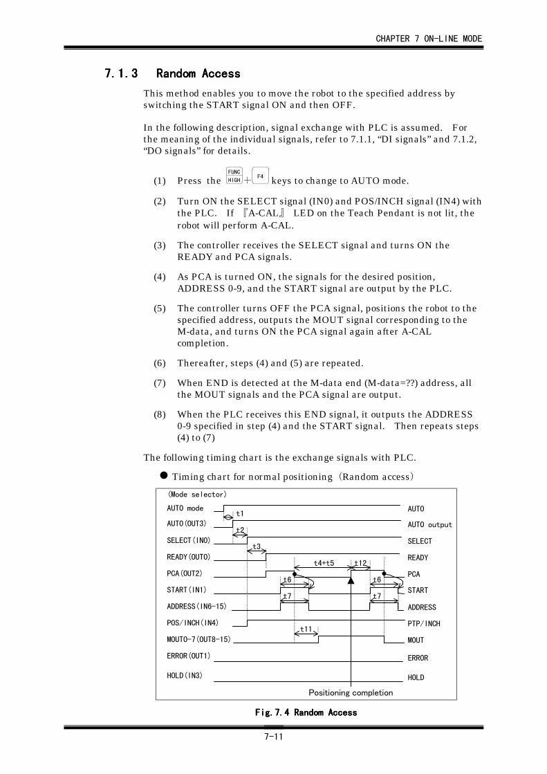
CHAPTER 7 ON-LINE MODE
7-11
7.1.37.1.37.1.37.1.3 Random AccessRandom AccessRandom AccessRandom Access
This method enables you to move the robot to the specified address byswitching the START signal ON and then OFF.
In the following description, signal exchange with PLC is assumed. Forthe meaning of the individual signals, refer to 7.1.1, “DI signals” and 7.1.2,“DO signals” for details.
(1) Press the FUNC
HIGH+F4 keys to change to AUTO mode.
(2) Turn ON the SELECT signal (IN0) and POS/INCH signal (IN4) withthe PLC. If 『A-CAL』 LED on the Teach Pendant is not lit, therobot will perform A-CAL.
(3) The controller receives the SELECT signal and turns ON theREADY and PCA signals.
(4) As PCA is turned ON, the signals for the desired position,ADDRESS 0-9, and the START signal are output by the PLC.
(5) The controller turns OFF the PCA signal, positions the robot to thespecified address, outputs the MOUT signal corresponding to theM-data, and turns ON the PCA signal again after A-CALcompletion.
(6) Thereafter, steps (4) and (5) are repeated.
(7) When END is detected at the M-data end (M-data=??) address, allthe MOUT signals and the PCA signal are output.
(8) When the PLC receives this END signal, it outputs the ADDRESS0-9 specified in step (4) and the START signal. Then repeats steps(4) to (7)
The following timing chart is the exchange signals with PLC.
Timing chart for normal positioning(Random access)
t6
t2
AUTO mode
AUT0(OUT3)
SELECT(IN0)
READY(OUT0)
PCA(OUT2)
START(IN1)
ADDRESS(IN6-15)
POS/INCH(IN4)
MOUT0-7(OUT8-15)
ERROR(OUT1)
AUTO
AUTO output
SELECT
READY
PCA
START
ADDRESS
PTP/INCH
MOUT
ERROR
(Mode selector)
t1
t3
t4+t5
t7
t12
t6
t7
t11
Positioning completion
HOLD(IN3) HOLD
Fig.7.Fig.7.Fig.7.Fig.7.4444 Random Access Random Access Random Access Random Access
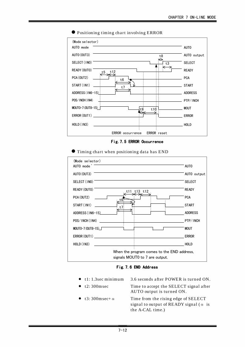
CHAPTER 7 ON-LINE MODE
7-12
Positioning timing chart involving ERROR
t12
t3
AUTO
AUTO output
SELECT
READY
PCA
START
ADDRESS
PTP/INCH
MOUT
ERROR
AUTO mode
ERROR(OUT1)
MOUT0-7(OUT8-15)
POS/INCH(IN4)
ADDRESS(IN6-15)
START(IN1)
PCA(OUT2)
READY(OUT0)
SELECT(IN0)
AUTO(OUT3)
ERROR occurrence ERROR reset
t5
t6
t7
t9 t10
t8
(Mode selector)
HOLDHOLD(IN3)
Fig.7.Fig.7.Fig.7.Fig.7.5555 ERROR Occurrence ERROR Occurrence ERROR Occurrence ERROR Occurrence
Timing chart when positioning data has END
t12
AUTO
AUTO output
SELECT
READY
PCA
START
ADDRESS
PTP/INCH
MOUT
ERROR
AUTO mode ゙
ERROR(OUT1)
MOUT0-7(OUT8-15)
POS/INCH(IN4)
ADDRESS(IN6-15)
START(IN1)
PCA(OUT2)
READY(OUT0)
SELECT(IN0)
AUTO(OUT3)
When the program comes to the END address,
signals MOUT0 to 7 are output.
t11 t13
t6
t7
(Mode selector)
HOLDHOLD(IN3)
Fig.7.Fig.7.Fig.7.Fig.7.6666 END Address END Address END Address END Address
• t1: 1.3sec minimum 3.6 seconds after POWER is turned ON.
• t2: 300msec Time to accept the SELECT signal afterAUTO output is turned ON.
• t3: 300msec+α Time from the rising edge of SELECTsignal to output of READY signal (α isthe A-CAL time.)
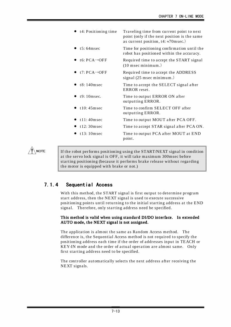
CHAPTER 7 ON-LINE MODE
7-13
• t4: Positioning time Traveling time from current point to nextpoint (only if the next position is the sameas current position, t4: ≈70msec.)
• t5: 64msec Time for positioning confirmation until therobot has positioned within the accuracy.
• t6: PCA→OFF Required time to accept the START signal(10 msec minimum.)
• t7: PCA→OFF Required time to accept the ADDRESSsignal (25 msec minimum.)
• t8: 140msec Time to accept the SELECT signal afterERROR reset.
• t9: 10msec. Time to output ERROR ON afteroutputting ERROR.
• t10: 45msec Time to confirm SELECT OFF afteroutputting ERROR.
• t11: 40msec Time to output MOUT after PCA OFF.
• t12: 30msec Time to accept STAR signal after PCA ON.
• t13: 10msec Time to output PCA after MOUT at ENDpoint.
If the robot performs positioning using the START/NEXT signal in conditionat the servo lock signal is OFF, it will take maximum 300msec beforestarting positioning (because it performs brake release without regardingthe motor is equipped with brake or not.)
7.1.47.1.47.1.47.1.4 Sequential AccessSequential AccessSequential AccessSequential Access
With this method, the START signal is first output to determine programstart address, then the NEXT signal is used to execute successivepositioning points until returning to the initial starting address at the ENDsignal. Therefore, only starting address need be specified.
This method is valid when using standard DI/DO interface. In extendedThis method is valid when using standard DI/DO interface. In extendedThis method is valid when using standard DI/DO interface. In extendedThis method is valid when using standard DI/DO interface. In extendedAUTO mode, AUTO mode, AUTO mode, AUTO mode, thethethethe NEXT signal is not assigned. NEXT signal is not assigned. NEXT signal is not assigned. NEXT signal is not assigned.
The application is almost the same as Random Access method. Thedifference is, the Sequential Access method is not required to specify thepositioning address each time if the order of addresses input in TEACH orKEY-IN mode and the order of actual operation are almost same. Onlyfirst starting address need to be specified.
The controller automatically selects the next address after receiving theNEXT signals.
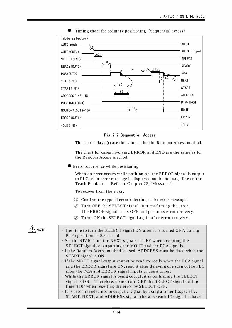
CHAPTER 7 ON-LINE MODE
7-14
Timing chart for ordinary positioning(Sequential access)
ERROR(OUT1)
(Mode selector)
t6
t4 t5
t6
t7
t12
AUTO
AUTO output
SELECT
READY
PCA
START
ADDRESS
PTP/INCH
MOUT
ERROR
AUTO mode
MOUT0-7(OUT8-15)
POS/INCH(IN4)
ADDRESS(IN6-15)
START(IN1)
PCA(OUT2)
READY(OUT0)
SELECT(IN0)
AUTO(OUT3)
NEXTNEXT(IN2)
t11
t3
t2
t1
HOLD(IN3) HOLD
Fig.7.Fig.7.Fig.7.Fig.7.7777 Sequential Access Sequential Access Sequential Access Sequential Access
The time delays (t) are the same as for the Random Access method.
The chart for cases involving ERROR and END are the same as forthe Random Access method.
Error occurrence while positioning
When an error occurs while positioning, the ERROR signal is outputto PLC or an error message is displayed on the message line on theTeach Pendant. (Refer to Chapter 23, “Message.”)
To recover from the error;
① Confirm the type of error referring to the error message.② Turn OFF the SELECT signal after confirming the error.
The ERROR signal turns OFF and performs error recovery.
③ Turns ON the SELECT signal again after error recovery.
・The time to turn the SELECT signal ON after it is turned OFF, duringPTP operation, is 0.5 second.
・Set the START and the NEXT signals to OFF when accepting theSELECT signal or outputting the MOUT and the PCA signals.
・If the Random Access method is used, ADDRESS must be fixed when theSTART signal is ON.
・If the MOUT signal output cannot be read correctly when the PCA signaland the ERROR signal are ON, read it after delaying one scan of the PLCafter the PCA and ERROR signal inputs or use a timer.
・While the ERROR signal is being output, it is confirming the SELECTsignal is ON. Therefore, do not turn OFF the SELECT signal duringtime “t10” when resetting the error by SELECT OFF.
・It is recommended not to output a signal by using a timer (Especially,START, NEXT, and ADDRESS signals) because each I/O signal is based
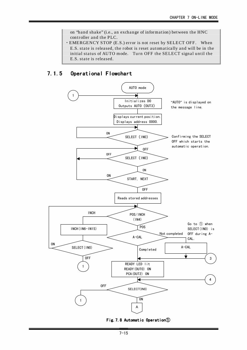
CHAPTER 7 ON-LINE MODE
7-15
on “hand shake” (i.e., an exchange of information) between the HNCcontroller and the PLC.
・EMERGENCY STOP (E.S.) error is not reset by SELECT OFF. WhenE.S. state is released, the robot is reset automatically and will be in theinitial status of AUTO mode. Turn OFF the SELECT signal until theE.S. state is released.
7.1.57.1.57.1.57.1.5 Operational FlowchartOperational FlowchartOperational FlowchartOperational Flowchart
ONSELECT(IN0)
POS
1
A
AUTO mode
Initializes DO
Outputs AUTO(OUT3)“AUTO” is displayed onthe message line.
Displays current position.
Displays address 0000.
SELECT(IN0)
SELECT(IN0)
START, NEXT
ON
OFF
ON
OFF
OFF
ON
OFF
ON
SELECT(IN0)
1
INCH
OFF
Completed
Not completed
Go to ① when
SELECT(IN0) is
OFF during A-
CAL.
1
Reads stored addresses
A-CAL
INCH(IN6-IN15)
READY LED lit
READY(OUT0) ON
PCA(OUT2) ON
A-CAL
3
4
Confirming the SELECT
OFF which starts the
automatic operation.
POS/INCH
(IN4)
Fig.7.Fig.7.Fig.7.Fig.7.8888 Automatic Operation Automatic Operation Automatic Operation Automatic Operation①①①①
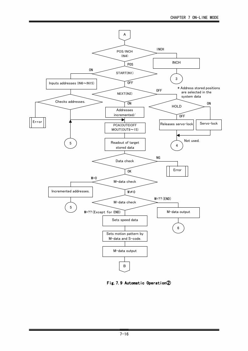
CHAPTER 7 ON-LINE MODE
7-16
ON
* Address stored positionsare selected in thesystem data
5
B
Data check
M-data check
M-data check
Error
Sets speed data
Sets motion pattern by
M-data and S-code.
M-data output
M-data output
6
M=??(END)
M=??(Except for END)
M≠0
M=0
OK
NG
POS
INCH
ON
OFF
OFF
ON
A
Addresses
incremented/
START(IN1)
INCH
3
NEXT(IN2)
Inputs addresses (IN6~IN15)
HOLD
Releases servo-lockPCA(OUT0)OFF
MOUT(OUT8~15)
Readout of target
stored data5
Error
4
Servo-lock
OFF
Checks addresses.
Not used.
POS/INCH
(IN4)
Incremented addresses.
Fig.7.Fig.7.Fig.7.Fig.7.9999 Automatic Operation Automatic Operation Automatic Operation Automatic Operation②②②②
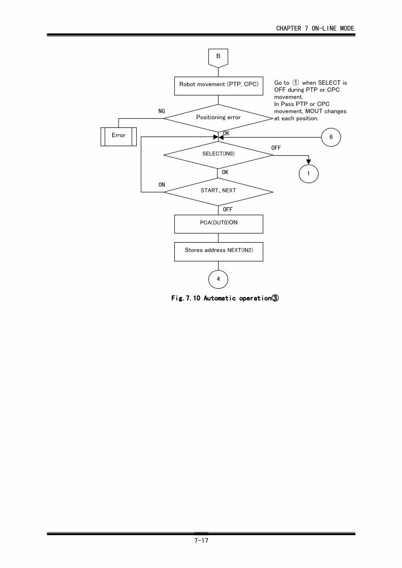
CHAPTER 7 ON-LINE MODE
7-17
PCA(OUT0)ON
Stores address NEXT(IN2)
4
Positioning error
Robot movement (PTP, CPC)
SELECT(IN0)
START、NEXT
Error 6
1
OK
OFF
OK
OFF
ON
NG
Go to ① when SELECT isOFF during PTP or CPCmovement.In Pass PTP or CPCmovement, MOUT changesat each position.
B
Fig.7.Fig.7.Fig.7.Fig.7.10101010 Automatic operation Automatic operation Automatic operation Automatic operation③③③③
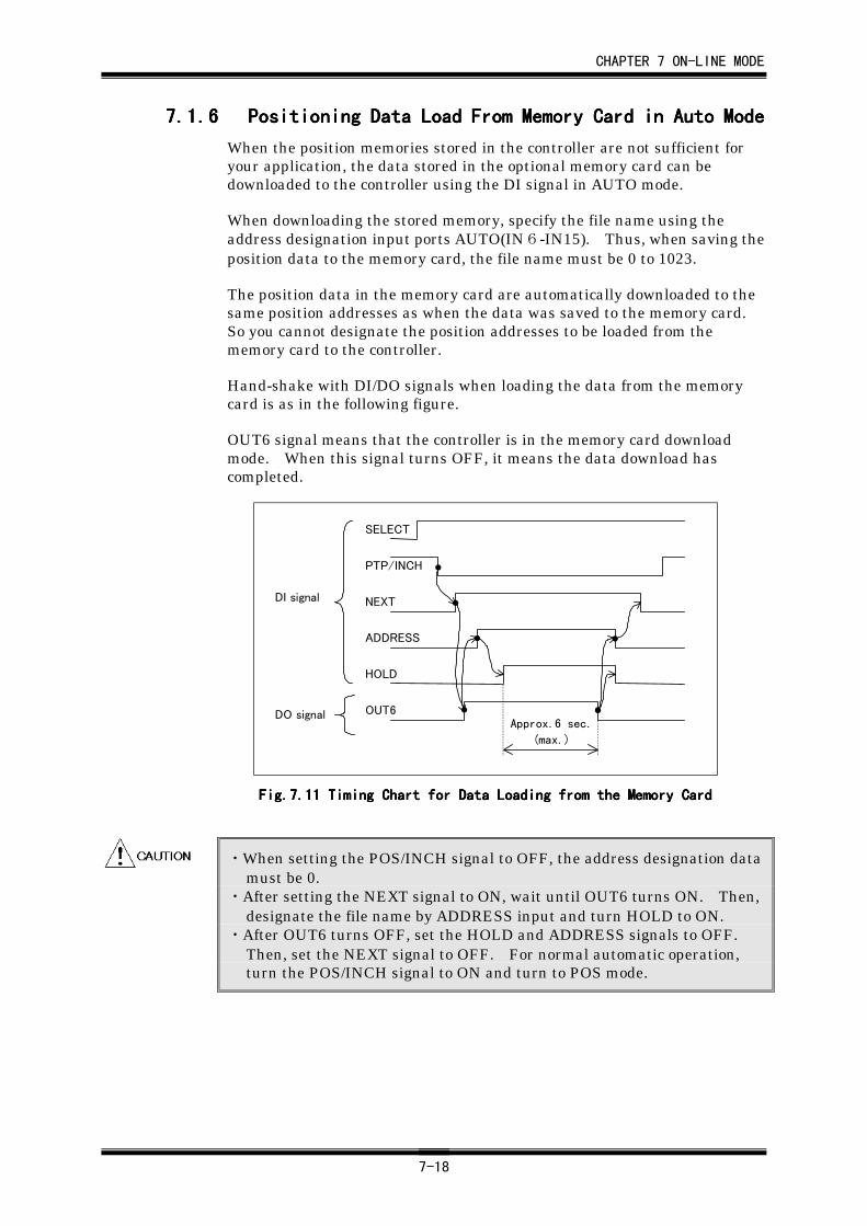
CHAPTER 7 ON-LINE MODE
7-18
7.1.67.1.67.1.67.1.6 Positioning Data Load From Memory Card in Auto ModePositioning Data Load From Memory Card in Auto ModePositioning Data Load From Memory Card in Auto ModePositioning Data Load From Memory Card in Auto Mode
When the position memories stored in the controller are not sufficient foryour application, the data stored in the optional memory card can bedownloaded to the controller using the DI signal in AUTO mode.
When downloading the stored memory, specify the file name using theaddress designation input ports AUTO(IN6-IN15). Thus, when saving theposition data to the memory card, the file name must be 0 to 1023.
The position data in the memory card are automatically downloaded to thesame position addresses as when the data was saved to the memory card.So you cannot designate the position addresses to be loaded from thememory card to the controller.
Hand-shake with DI/DO signals when loading the data from the memorycard is as in the following figure.
OUT6 signal means that the controller is in the memory card downloadmode. When this signal turns OFF, it means the data download hascompleted.
Approx.6 sec.
(max.)
SELECT
PTP/INCH
NEXT
ADDRESS
OUT6
HOLD
DI signal
DO signal
Fig.7.Fig.7.Fig.7.Fig.7.11111111 Timing Chart for Data Loading from the Memory Card Timing Chart for Data Loading from the Memory Card Timing Chart for Data Loading from the Memory Card Timing Chart for Data Loading from the Memory Card
・When setting the POS/INCH signal to OFF, the address designation datamust be 0.
・After setting the NEXT signal to ON, wait until OUT6 turns ON. Then,designate the file name by ADDRESS input and turn HOLD to ON.
・After OUT6 turns OFF, set the HOLD and ADDRESS signals to OFF.Then, set the NEXT signal to OFF. For normal automatic operation,turn the POS/INCH signal to ON and turn to POS mode.
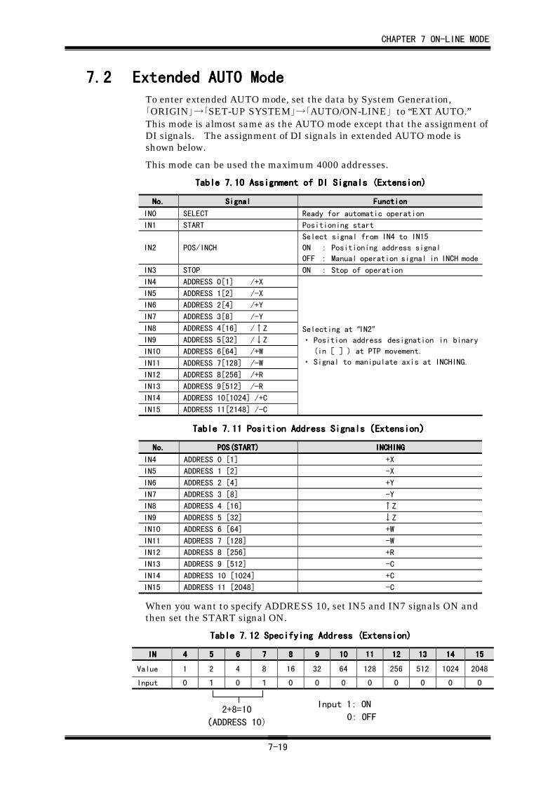
CHAPTER 7 ON-LINE MODE
7-19
7.27.27.27.2 Extended AUTO ModeExtended AUTO ModeExtended AUTO ModeExtended AUTO ModeTo enter extended AUTO mode, set the data by System Generation,「ORIGIN」→「SET-UP SYSTEM」→「AUTO/ON-LINE」 to “EXT AUTO.”This mode is almost same as the AUTO mode except that the assignment ofDI signals. The assignment of DI signals in extended AUTO mode isshown below.
This mode can be used the maximum 4000 addresses.
Table 7.Table 7.Table 7.Table 7.10101010 Assignment of DI Signals (Extension) Assignment of DI Signals (Extension) Assignment of DI Signals (Extension) Assignment of DI Signals (Extension)
No.No.No.No. SignalSignalSignalSignal FunctionFunctionFunctionFunction
IN0 SELECT Ready for automatic operation
IN1 START Positioning start
IN2 POS/INCH
Select signal from IN4 to IN15
ON : Positioning address signal
OFF : Manual operation signal in INCH mode
IN3 STOP ON : Stop of operation
IN4 ADDRESS 0[1] /+X
IN5 ADDRESS 1[2] /-X
IN6 ADDRESS 2[4] /+Y
IN7 ADDRESS 3[8] /-Y
IN8 ADDRESS 4[16] /↑Z
IN9 ADDRESS 5[32] /↓Z
IN10 ADDRESS 6[64] /+W
IN11 ADDRESS 7[128] /-W
IN12 ADDRESS 8[256] /+R
IN13 ADDRESS 9[512] /-R
IN14 ADDRESS 10[1024] /+C
IN15 ADDRESS 11[2148] /-C
Selecting at “IN2”・ Position address designation in binary
(in[ ]) at PTP movement.
・ Signal to manipulate axis at INCHING.
Table 7.Table 7.Table 7.Table 7.11111111 Position Address Signals Position Address Signals Position Address Signals Position Address Signals((((ExtensionExtensionExtensionExtension))))
No.No.No.No. POS(START)POS(START)POS(START)POS(START) INCHINGINCHINGINCHINGINCHING
IN4 ADDRESS 0 [1] +X
IN5 ADDRESS 1 [2] -X
IN6 ADDRESS 2 [4] +Y
IN7 ADDRESS 3 [8] -Y
IN8 ADDRESS 4 [16] ↑Z
IN9 ADDRESS 5 [32] ↓Z
IN10 ADDRESS 6 [64] +W
IN11 ADDRESS 7 [128] -W
IN12 ADDRESS 8 [256] +R
IN13 ADDRESS 9 [512] -C
IN14 ADDRESS 10 [1024] +C
IN15 ADDRESS 11 [2048] -C
When you want to specify ADDRESS 10, set IN5 and IN7 signals ON andthen set the START signal ON.
Table 7.Table 7.Table 7.Table 7.12121212 Specifying Address (Extension) Specifying Address (Extension) Specifying Address (Extension) Specifying Address (Extension)
ININININ 4444 5555 6666 7777 8888 9999 10101010 11111111 12121212 13131313 14141414 15151515
Value 1 2 4 8 16 32 64 128 256 512 1024 2048
Input 0 1 0 1 0 0 0 0 0 0 0 0
2+8=10
(ADDRESS 10)
Input 1: ON
0: OFF
CHAPTER 7 ON-LINE MODE
7-20
The function of downloading the position data from the memory card is notsupported in extended AUTO mode
7.37.37.37.3 ON-LINE ModeON-LINE ModeON-LINE ModeON-LINE ModeON-LINE mode enables a robot to perform automatic operation by using ahost computer and HAC (Hirata Assembly cell Controller) via RS232Cinterface.
In this mode, communication with external devices is available with ourcommunication software. Refer to the separate instruction manual,HRCS-RⅣ for details.
In this mode, robot speed is set by the System Parameter, F-code, and theMOVE command.
CHAPTER 8 DATA EDITING
8-1
CHAPTER 8CHAPTER 8CHAPTER 8CHAPTER 8 Data EditingData EditingData EditingData Editing
8.18.18.18.1 Entering END Point (M-Data=??)Entering END Point (M-Data=??)Entering END Point (M-Data=??)Entering END Point (M-Data=??)After creating position data in KEY-IN or TEACH mode, an END point (M-data=??) should be specified. The END point (M-data=??) indicates the endof position data, and should be specified at the end of the position data. Inautomatic operation mode or CHECK mode, positioning to the END point(M-data=??) will not be performed.
(1) Set the Teach Pendant to KEY-IN mode (FUNC
HIGH+F1 ) or TEACH mode
(FUNC
HIGH+F2 ).
(2) Display the address data for which an END point (M-data=??) willbe specified.
(3) Press the END key. The message “END WRITE OK?” will be dis-played on the message line and a buzzer sounds.
(4) Confirm that the address to be set is correct. Then, press theENTER key, the END point (M-data=??) will be set.
If you have specified a wrong address, press any key other than theENTER key to cancel the END point setting operation.
・ The “END point” used in this chapter means a point where a series of ro-bot movements is to be ended. The addresses following the one forwhich an END point is specified can be used as regular addresses.
・ The M-data display section of an address for which an END point hasbeen specified, “??” is displayed. This “??” is common for all the modedisplays. To unset an END point, specify numerical values for the M-data display section of an address for which the END point has been set.When numerical values are assigned, the M-data will be treated as nor-mal position data.
・ When you are setting an END point, the data for X, Y, Z, W, R, and C arealso checked. Therefore, if the data for X, Y, Z, W, R, and C are not cor-rect, the END point cannot be specified.
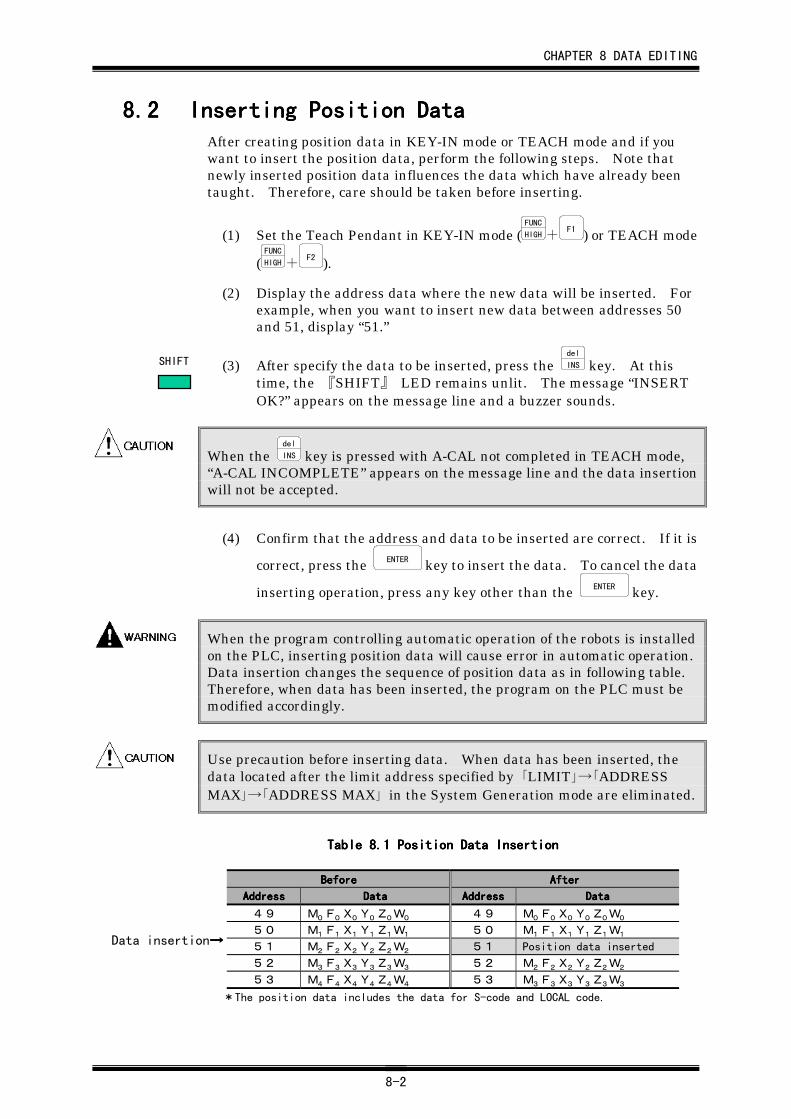
CHAPTER 8 DATA EDITING
8-2
8.28.28.28.2 Inserting Position DataInserting Position DataInserting Position DataInserting Position DataAfter creating position data in KEY-IN mode or TEACH mode and if youwant to insert the position data, perform the following steps. Note thatnewly inserted position data influences the data which have already beentaught. Therefore, care should be taken before inserting.
(1) Set the Teach Pendant in KEY-IN mode (FUNC
HIGH+F1 ) or TEACH mode
(FUNC
HIGH+F2 ).
(2) Display the address data where the new data will be inserted. Forexample, when you want to insert new data between addresses 50and 51, display “51.”
(3) After specify the data to be inserted, press the del
INS key. At thistime, the 『SHIFT』 LED remains unlit. The message “INSERTOK?” appears on the message line and a buzzer sounds.
When the del
INS key is pressed with A-CAL not completed in TEACH mode,“A-CAL INCOMPLETE” appears on the message line and the data insertionwill not be accepted.
(4) Confirm that the address and data to be inserted are correct. If it is
correct, press the ENTER key to insert the data. To cancel the data
inserting operation, press any key other than the ENTER key.
When the program controlling automatic operation of the robots is installedon the PLC, inserting position data will cause error in automatic operation.Data insertion changes the sequence of position data as in following table.Therefore, when data has been inserted, the program on the PLC must bemodified accordingly.
Use precaution before inserting data. When data has been inserted, thedata located after the limit address specified by 「LIMIT」→「ADDRESSMAX」→「ADDRESS MAX」 in the System Generation mode are eliminated.
Table 8.Table 8.Table 8.Table 8.1111 Position Data Insertion Position Data Insertion Position Data Insertion Position Data Insertion
BeforeBeforeBeforeBefore AfterAfterAfterAfter
AddressAddressAddressAddress DataDataDataData AddressAddressAddressAddress DataDataDataData
49 M0 F0 X0 Y0 Z0 W0 49 M0 F0 X0 Y0 Z0 W050 M1 F1 X1 Y1 Z1 W1 50 M1 F1 X1 Y1 Z1 W151 M2 F2 X2 Y2 Z2 W2 51 Position data inserted
52 M3 F3 X3 Y3 Z3 W3 52 M2 F2 X2 Y2 Z2 W253 M4 F4 X4 Y4 Z4 W4 53 M3 F3 X3 Y3 Z3 W3
*The position data includes the data for S-code and LOCAL code.
SHIFT
Data insertion→→→→
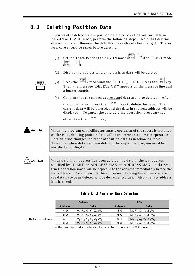
CHAPTER 8 DATA EDITING
8-3
8.38.38.38.3 Deleting Position DataDeleting Position DataDeleting Position DataDeleting Position DataIf you want to delete certain position data after creating position data inKEY-IN or TEACH mode, perform the following steps. Note that deletionof position data influences the data that have already been taught. There-fore, care should be taken before deleting.
(1) Set the Teach Pendant to KEY-IN mode (FUNC
HIGH+F1 ) or TEACH mode
(FUNC
HIGH+F2 ).
(2) Display the address where the position data will be deleted.
(3) Press the SHIFT
key to blink the 『SHIFT』 LED. Press the del
INS key.Then, the message “DELETE OK?” appears on the message line anda buzzer sounds.
(4) Confirm that the correct address and data are to be deleted. After
the confirmation, press the ENTER key to delete the data. Thecurrent data will be deleted, and the data in the next address will bedisplayed. To cancel the data deleting operation, press any key
other than the ENTER key.
When the program controlling automatic operation of the robots is installedon the PLC, deleting position data will cause error in automatic operation.Data deletion changes the order of position data as in following table.Therefore, when data has been deleted, the sequencer program must bemodified accordingly.
When data in an address has been deleted, the data in the last addressspecified by 「LIMIT」→「ADDRESS MAX」→「ADDRESS MAX」 in the Sys-tem Generation mode will be copied into the address immediately before thelast address. Data in each of the addresses following the address wherethe data have been deleted will be decremented one. Also, the last addressis initialized.
Table 8.Table 8.Table 8.Table 8. 2222 Position Data Deletion Position Data Deletion Position Data Deletion Position Data Deletion
BeforeBeforeBeforeBefore AfterAfterAfterAfter
AddressAddressAddressAddress DataDataDataData AddressAddressAddressAddress DataDataDataData
49 M0 F0 X0 Y0 Z0 W0 49 M0 F0 X0 Y0 Z0 W050 M1 F1 X1 Y1 Z1 W1 50 M1 F1 X1 Y1 Z1 W151 M2 F2 X2 Y2 Z2 W2 51 M3 F3 X3 Y3 Z3 W352 M3 F3 X3 Y3 Z3 W3 52 M4 F4 X4 Y4 Z4 W4
*The position data includes the data for S-code and LOCAL code.
SHIFT
Data Deletion→→→→
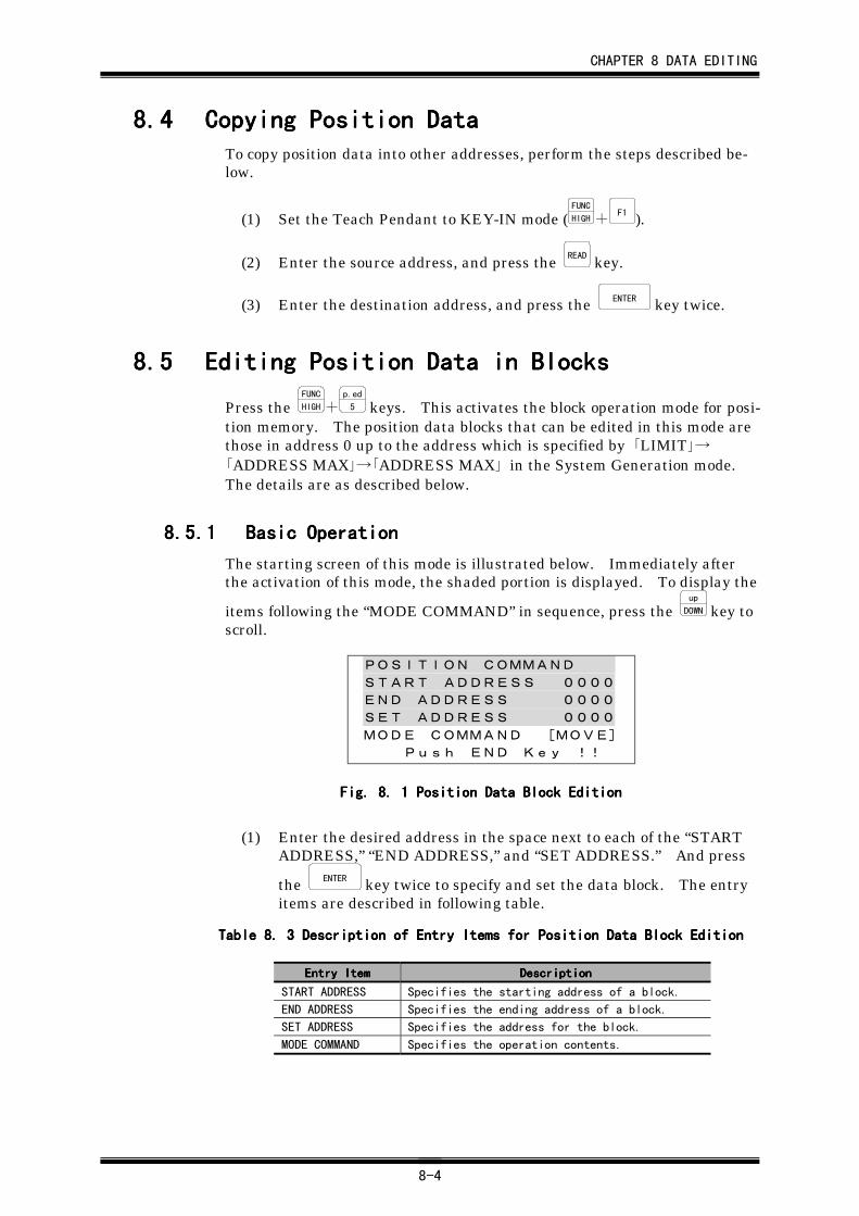
CHAPTER 8 DATA EDITING
8-4
8.48.48.48.4 Copying Position DataCopying Position DataCopying Position DataCopying Position DataTo copy position data into other addresses, perform the steps described be-low.
(1) Set the Teach Pendant to KEY-IN mode (FUNC
HIGH+F1 ).
(2) Enter the source address, and press the READ key.
(3) Enter the destination address, and press the ENTER key twice.
8.58.58.58.5 Editing Position Data in BlocksEditing Position Data in BlocksEditing Position Data in BlocksEditing Position Data in Blocks
Press the FUNC
HIGH+p.ed
5 keys. This activates the block operation mode for posi-tion memory. The position data blocks that can be edited in this mode arethose in address 0 up to the address which is specified by 「LIMIT」→「ADDRESS MAX」→「ADDRESS MAX」 in the System Generation mode.The details are as described below.
8.5.18.5.18.5.18.5.1 Basic OperationBasic OperationBasic OperationBasic Operation
The starting screen of this mode is illustrated below. Immediately afterthe activation of this mode, the shaded portion is displayed. To display the
items following the “MODE COMMAND” in sequence, press the up
DOWN key toscroll.
POSITION COMMAND
START ADDRESS 0000
END ADDRESS 0000
SET ADDRESS 0000
MODE COMMAND [MOVE]
Push END Key !!
Fig. 8. Fig. 8. Fig. 8. Fig. 8. 1111 Position Data Block Edition Position Data Block Edition Position Data Block Edition Position Data Block Edition
(1) Enter the desired address in the space next to each of the “STARTADDRESS,” “END ADDRESS,” and “SET ADDRESS.” And press
the ENTER key twice to specify and set the data block. The entryitems are described in following table.
Table 8.Table 8.Table 8.Table 8. 3333 Description of Entry Items for Position Data Block Edition Description of Entry Items for Position Data Block Edition Description of Entry Items for Position Data Block Edition Description of Entry Items for Position Data Block Edition
Entry ItemEntry ItemEntry ItemEntry Item DescriptionDescriptionDescriptionDescription
START ADDRESS Specifies the starting address of a block.
END ADDRESS Specifies the ending address of a block.
SET ADDRESS Specifies the address for the block.
MODE COMMAND Specifies the operation contents.
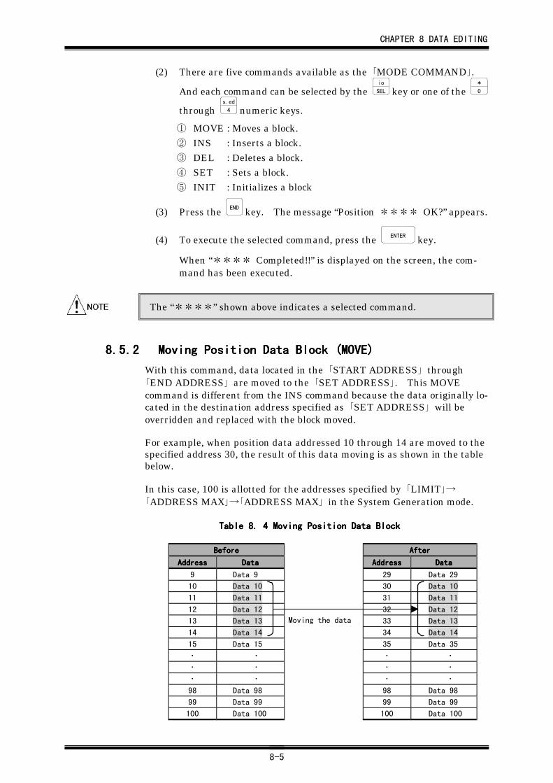
CHAPTER 8 DATA EDITING
8-5
(2) There are five commands available as the 「MODE COMMAND」.
And each command can be selected by the io
SEL key or one of the *
0
through s.ed
4 numeric keys.
① MOVE : Moves a block.② INS : Inserts a block.③ DEL : Deletes a block.④ SET : Sets a block.⑤ INIT : Initializes a block
(3) Press the END key. The message “Position **** OK?” appears.
(4) To execute the selected command, press the ENTER key.
When “**** Completed!!” is displayed on the screen, the com-mand has been executed.
The “****” shown above indicates a selected command.
8.5.28.5.28.5.28.5.2 Moving Position Data Block (MOVE)Moving Position Data Block (MOVE)Moving Position Data Block (MOVE)Moving Position Data Block (MOVE)
With this command, data located in the 「START ADDRESS」 through「END ADDRESS」 are moved to the 「SET ADDRESS」. This MOVEcommand is different from the INS command because the data originally lo-cated in the destination address specified as 「SET ADDRESS」 will beoverridden and replaced with the block moved.
For example, when position data addressed 10 through 14 are moved to thespecified address 30, the result of this data moving is as shown in the tablebelow.
In this case, 100 is allotted for the addresses specified by 「LIMIT」→「ADDRESS MAX」→「ADDRESS MAX」 in the System Generation mode.
Table 8. Table 8. Table 8. Table 8. 4444 Moving Position Data Block Moving Position Data Block Moving Position Data Block Moving Position Data Block
BeforeBeforeBeforeBefore AfterAfterAfterAfter
AddressAddressAddressAddress DataDataDataData AddressAddressAddressAddress DataDataDataData
9 Data 9 29 Data 29
10 Data 10 30 Data 10
11 Data 11 31 Data 11
12 Data 12 32 Data 12
13 Data 13 33 Data 13
14 Data 14 34 Data 14
15 Data 15 35 Data 35
・ ・ ・ ・
・ ・ ・ ・
・ ・ ・ ・
98 Data 98 98 Data 98
99 Data 99 99 Data 99
100 Data 100 100 Data 100
Moving the data
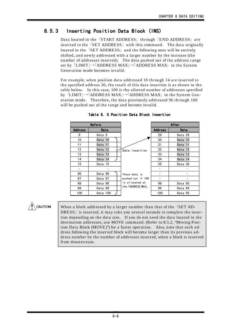
CHAPTER 8 DATA EDITING
8-6
8.5.38.5.38.5.38.5.3 Inserting Position Data Block (INS)Inserting Position Data Block (INS)Inserting Position Data Block (INS)Inserting Position Data Block (INS)
Data located in the 「START ADDRESS」 through 「END ADDRESS」 areinserted to the 「SET ADDRESS」 with this command. The data originallylocated in the 「SET ADDRESS」 and the following ones will be entirelyshifted, and newly addressed with a larger number by the increase (thenumber of addresses inserted). The data pushed out of the address rangeset by 「LIMIT」→「ADDRESS MAX」→「ADDRESS MAX」 in the SystemGeneration mode becomes invalid.
For example, when position data addressed 10 through 14 are inserted tothe specified address 30, the result of this data insertion is as shown in thetable below. In this case, 100 is the allotted number of addresses specifiedby 「LIMIT」→「ADDRESS MAX」→「ADDRESS MAX」 in the System Gen-eration mode. Therefore, the data previously addressed 96 through 100will be pushed out of the range and become invalid.
Table 8. Table 8. Table 8. Table 8. 5555 Position Data Block Insertion Position Data Block Insertion Position Data Block Insertion Position Data Block Insertion
BeforeBeforeBeforeBefore AfterAfterAfterAfter
AddressAddressAddressAddress DataDataDataData AddressAddressAddressAddress DataDataDataData
9 Data 9 29 Data 29
10 Data 10 30 Data 10
11 Data 11 31 Data 11
12 Data 12 32 Data 12
13 Data 13 33 Data 13
14 Data 14 34 Data 14
15 Data 15 35 Data 30
・ ・ ・ ・
96 Data 96 ・ ・
97 Data 97 ・ ・
98 Data 98 98 Data 93
99 Data 99 99 Data 94
100 Data 100 100 Data 95
When a block addressed by a larger number than that of the 「SET AD-DRESS」 is inserted, it may take you several seconds to complete the inser-tion depending on the data size. If you do not need the data located in thedestination addresses, use MOVE command. (Refer to 8.5.2, “Moving Posi-tion Data Block (MOVE)”) for a faster operation. Also, note that each ad-dress following the inserted block will become larger than its previous ad-dress number by the number of addresses inserted, when a block is insertedfrom downstream.
These data is
pushed out if 100
is allocated at
the 「ADDRESS MAX」.
Data insertion
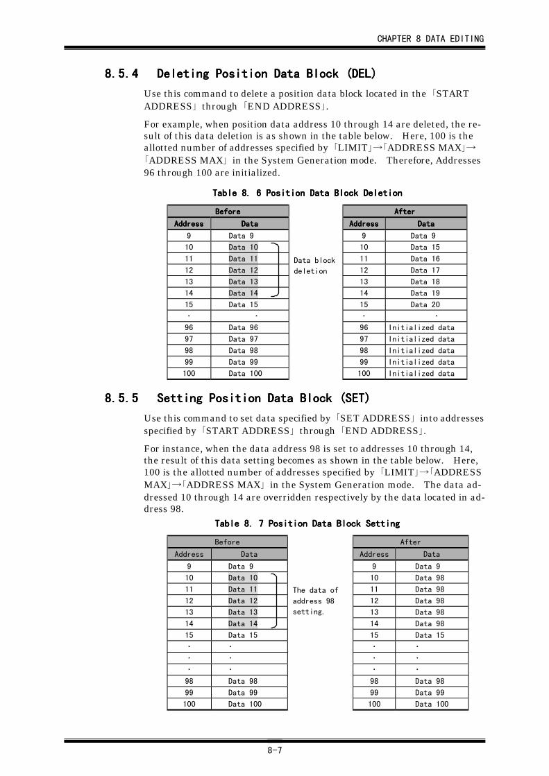
CHAPTER 8 DATA EDITING
8-7
8.5.48.5.48.5.48.5.4 Deleting Position Data Block (DEL)Deleting Position Data Block (DEL)Deleting Position Data Block (DEL)Deleting Position Data Block (DEL)
Use this command to delete a position data block located in the 「STARTADDRESS」 through 「END ADDRESS」.
For example, when position data address 10 through 14 are deleted, the re-sult of this data deletion is as shown in the table below. Here, 100 is theallotted number of addresses specified by 「LIMIT」→「ADDRESS MAX」→「ADDRESS MAX」 in the System Generation mode. Therefore, Addresses96 through 100 are initialized.
Table 8. Table 8. Table 8. Table 8. 6666 Position Data Block Deletion Position Data Block Deletion Position Data Block Deletion Position Data Block Deletion
BeforeBeforeBeforeBefore AfterAfterAfterAfter
AddressAddressAddressAddress DataDataDataData AddressAddressAddressAddress DataDataDataData
9 Data 9 9 Data 9
10 Data 10 10 Data 15
11 Data 11 11 Data 16
12 Data 12 12 Data 17
13 Data 13 13 Data 18
14 Data 14 14 Data 19
15 Data 15 15 Data 20
・ ・ ・ ・
96 Data 96 96 Initialized data
97 Data 97 97 Initialized data
98 Data 98 98 Initialized data
99 Data 99 99 Initialized data
100 Data 100 100 Initialized data
8.5.58.5.58.5.58.5.5 Setting Position Data Block (SET)Setting Position Data Block (SET)Setting Position Data Block (SET)Setting Position Data Block (SET)
Use this command to set data specified by 「SET ADDRESS」 into addressesspecified by 「START ADDRESS」 through 「END ADDRESS」.
For instance, when the data address 98 is set to addresses 10 through 14,the result of this data setting becomes as shown in the table below. Here,100 is the allotted number of addresses specified by 「LIMIT」→「ADDRESSMAX」→「ADDRESS MAX」 in the System Generation mode. The data ad-dressed 10 through 14 are overridden respectively by the data located in ad-dress 98.
Table 8. Table 8. Table 8. Table 8. 7777 Position Data Block Setting Position Data Block Setting Position Data Block Setting Position Data Block Setting
Before After
Address Data Address Data
9 Data 9 9 Data 9
10 Data 10 10 Data 98
11 Data 11 11 Data 98
12 Data 12 12 Data 98
13 Data 13 13 Data 98
14 Data 14 14 Data 98
15 Data 15 15 Data 15
・ ・ ・ ・
・ ・ ・ ・
・ ・ ・ ・
98 Data 98 98 Data 98
99 Data 99 99 Data 99
100 Data 100 100 Data 100
The data of
address 98
setting.
Data block
deletion
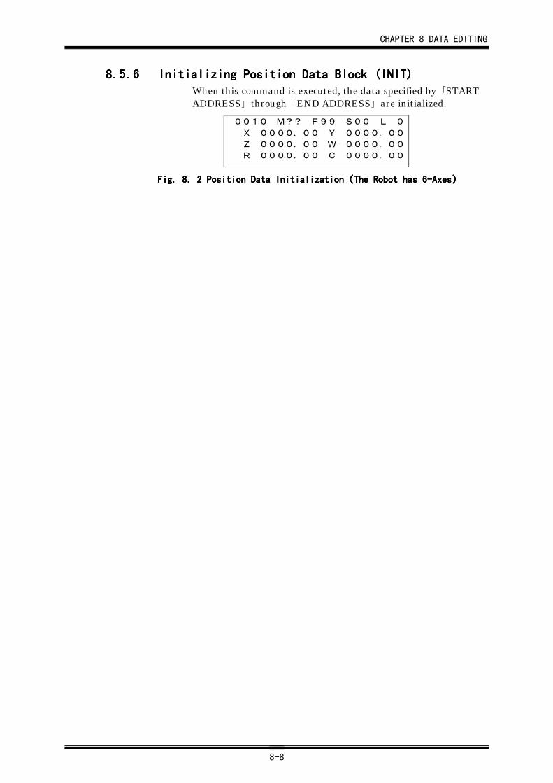
CHAPTER 8 DATA EDITING
8-8
8.5.68.5.68.5.68.5.6 Initializing Position Data Block (INIT)Initializing Position Data Block (INIT)Initializing Position Data Block (INIT)Initializing Position Data Block (INIT)When this command is executed, the data specified by 「STARTADDRESS」 through 「END ADDRESS」 are initialized.
0010 M?? F99 S00 L 0
X 0000.00 Y 0000.00
Z 0000.00 W 0000.00
R 0000.00 C 0000.00
Fig. 8. Fig. 8. Fig. 8. Fig. 8. 2222 Position Data Initialization Position Data Initialization Position Data Initialization Position Data Initialization((((The Robot has 6-AxesThe Robot has 6-AxesThe Robot has 6-AxesThe Robot has 6-Axes))))
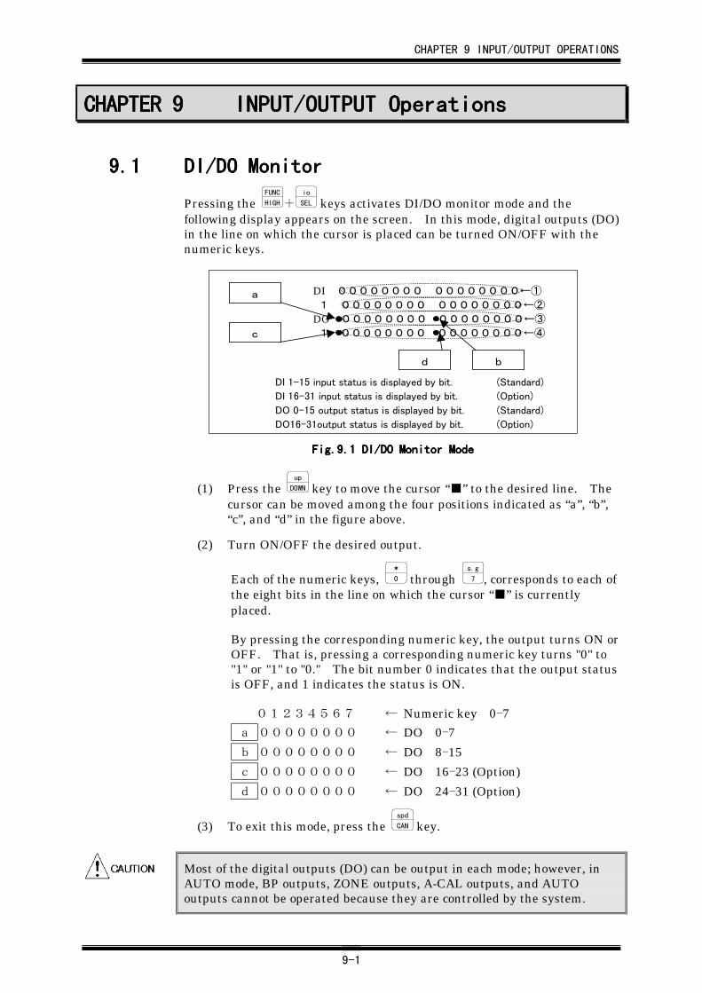
CHAPTER 9 INPUT/OUTPUT OPERATIONS
9-1
CHAPTER 9CHAPTER 9CHAPTER 9CHAPTER 9 INPUT/OUTPUT OperationsINPUT/OUTPUT OperationsINPUT/OUTPUT OperationsINPUT/OUTPUT Operations
9.19.19.19.1 DI/DO MonitorDI/DO MonitorDI/DO MonitorDI/DO Monitor
Pressing the FUNC
HIGH+io
SEL keys activates DI/DO monitor mode and thefollowing display appears on the screen. In this mode, digital outputs (DO)in the line on which the cursor is placed can be turned ON/OFF with thenumeric keys.
DI 00000000 00000000←① 1 00000000 00000000←②DO 00000000 00000000←③ 1 00000000 00000000←④
DI 1-15 input status is displayed by bit. (Standard)
DI 16-31 input status is displayed by bit. (Option)
DO 0-15 output status is displayed by bit. (Standard)
DO16-31output status is displayed by bit. (Option)
a
c
d b
Fig.9.Fig.9.Fig.9.Fig.9.1111 DI/DO Monitor Mode DI/DO Monitor Mode DI/DO Monitor Mode DI/DO Monitor Mode
(1) Press the up
DOWN key to move the cursor “■” to the desired line. Thecursor can be moved among the four positions indicated as “a”, “b”,“c”, and “d” in the figure above.
(2) Turn ON/OFF the desired output.
Each of the numeric keys, *
0 through s.g
7 , corresponds to each ofthe eight bits in the line on which the cursor “■” is currentlyplaced.
By pressing the corresponding numeric key, the output turns ON orOFF. That is, pressing a corresponding numeric key turns "0" to"1" or "1" to "0." The bit number 0 indicates that the output statusis OFF, and 1 indicates the status is ON.
01234567 ← Numeric key 0-7
a 00000000 ← DO 0-7
b 00000000 ← DO 8-15
c 00000000 ← DO 16-23 (Option)
d 00000000 ← DO 24-31 (Option)
(3) To exit this mode, press the spd
CAN key.
Most of the digital outputs (DO) can be output in each mode; however, inAUTO mode, BP outputs, ZONE outputs, A-CAL outputs, and AUTOoutputs cannot be operated because they are controlled by the system.
CHAPTER 9 INPUT/OUTPUT OPERATIONS
9-2
9.29.29.29.2 Manually Outputting M-Data SignalsManually Outputting M-Data SignalsManually Outputting M-Data SignalsManually Outputting M-Data SignalsIn KEY-IN, TEACH, or CHECK mode, the controller gives to its outputsignals the outputs corresponding to the values set as M-data. Whenoutput signals of the controller are used, you can check the operations ofother components through operation of the output signals in CHECK modeor during teaching. For M-data, refer to "16.4.1, List of M-Data Functions."
In this section, steps to manually output M-data are described.
(1) Select KEY-IN, TEACH, or CHECK mode by the Teach Pendant.
(2) Move the cursor to the position for M-data.
(3) Press the keys corresponding to the value of M-data to be output.
For example, press the cal
1 key and then, the *
0 key to set the M-data to 10.
(4) Press the m.c
M.OUT key. The output conforming to the M-data value,displayed immediately before the key was pressed, will be given tothe output signal of the controller.
・ If you press the ENTER key before pressing the m.c
M.OUT key, the positiondata, the address of which is currently displayed, will be entered and set.
When you have pressed the ENTER key by mistake, the confirmingmessage "ENTER OK?" appears on the message line. Press any key
other than the ENTER key to cancel the position data setting operation.・ The output operation will be retained until the next output is given. If
the mode is switched into ON-LINE, or the power supply is interrupted,all the outputs will be turned OFF.
CHAPTER 10 HOLD FUNCTION
10-1
CHAPTER 10CHAPTER 10CHAPTER 10CHAPTER 10 HOLD FunctionHOLD FunctionHOLD FunctionHOLD Function
Currently this function is not used for this system.
Normally, all axes are held in TEACH and CHECK mode. However, whenthe coordinates system display is set to “8”, the HOLD function will becancelled and only the axes equipped with a brake are held. Also, in KEY-IN mode, the HOLD function will be cancelled and only the axes equippedwith a brake are held by the brake.
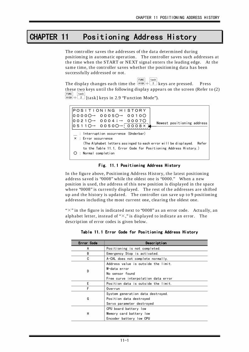
CHAPTER 11 POSITIONING ADDRESS HISTORY
11-1
CHAPTER 11CHAPTER 11CHAPTER 11CHAPTER 11 Positioning Address HistoryPositioning Address HistoryPositioning Address HistoryPositioning Address History
The controller saves the addresses of the data determined duringpositioning in automatic operation. The controller saves such addresses atthe time when the START or NEXT signal enters the leading edge. At thesame time, the controller saves whether the positioning data has beensuccessfully addressed or not.
The display changes each time the FUNC
HIGH+task
2 keys are pressed. Pressthese two keys until the following display appears on the screen (Refer to (2)FUNC
HIGH+task
2 [task] keys in 2.9 “Function Mode”).
POSITIONING HISTORY0000○→ 0005○→ 0010○0021○→ 0004i→ 0007○0511○→ 0050○→ 0008×
: Interruption occurrence (Underbar)
× : Error occurrence
(The Alphabet letters assinged to each error will be displayed. Refer
to the Table 11.1, Error Code for Positioning Address History.)
○ : Normal completion
Newest positioning address
Fig. 11.Fig. 11.Fig. 11.Fig. 11.1111 Positioning Address History Positioning Address History Positioning Address History Positioning Address History
In the figure above, Positioning Address History, the latest positioningaddress saved is “0008” while the oldest one is “0000.” When a newposition is used, the address of this new position is displayed in the spacewhere “0008” is currently displayed. The rest of the addresses are shiftedup and the history is updated. The controller can save up to 9 positioningaddresses including the most current one, clearing the oldest one.
“×” in the figure is indicated next to “0008” as an error code. Actually, analphabet letter, instead of “×,” is displayed to indicate an error. Thedescription of error codes is given below.
Table 11.Table 11.Table 11.Table 11.1111 Error Code for Positioning Address History Error Code for Positioning Address History Error Code for Positioning Address History Error Code for Positioning Address History
Error CodeError CodeError CodeError Code DescriptionDescriptionDescriptionDescription
A Positioning is not completed.
B Emergency Stop is activated.
C A-CAL does not complete normally.
D
Address value is outside the limit.
M-data error
No sensor found
Free curve interpolation data error
E Position data is outside the limit.
F Overrun
G
System generation data destroyed.
Position data destroyed
Servo parameter destroyed
H
CPU board battery low
Memory card battery low
Encoder battery low CPU
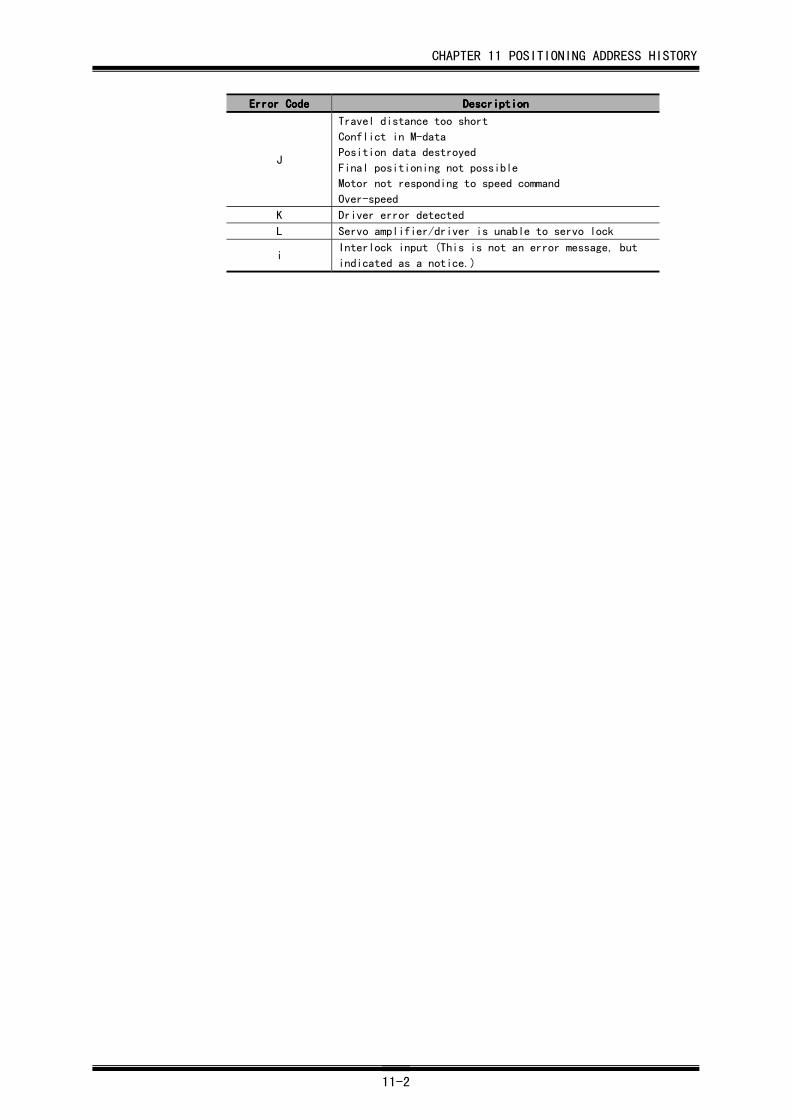
CHAPTER 11 POSITIONING ADDRESS HISTORY
11-2
Error CodeError CodeError CodeError Code DescriptionDescriptionDescriptionDescription
J
Travel distance too short
Conflict in M-data
Position data destroyed
Final positioning not possible
Motor not responding to speed command
Over-speed
K Driver error detected
L Servo amplifier/driver is unable to servo lock
iInterlock input (This is not an error message, but
indicated as a notice.)
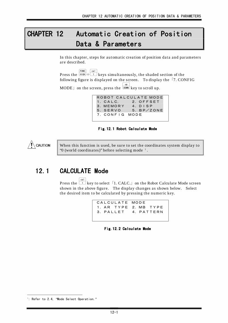
CHAPTER 12 AUTOMATIC CREATION OF POSITION DATA & PARAMETERS
12-1
CHAPTER 12CHAPTER 12CHAPTER 12CHAPTER 12 Automatic Creation of PositionAutomatic Creation of PositionAutomatic Creation of PositionAutomatic Creation of Position
Data & ParametersData & ParametersData & ParametersData & Parameters
In this chapter, steps for automatic creation of position data and parametersare described.
Press the FUNC
HIGH+cal
1 keys simultaneously, the shaded section of thefollowing figure is displayed on the screen. To display the 「7. CONFIG
MODE」 on the screen, press the up
DOWN key to scroll up.
ROBOT CALCULATE MODE1.CALC. 2.OFFSET3.MEMORY 4.DISP5.SERVO 5.BP/ZONE7.CONFIG MODE
Fig.12.Fig.12.Fig.12.Fig.12.1111 Robot Calculate Mode Robot Calculate Mode Robot Calculate Mode Robot Calculate Mode
When this function is used, be sure to set the coordinates system display to“0 (world coordinates)” before selecting mode i .
12.112.112.112.1 CALCULATE ModeCALCULATE ModeCALCULATE ModeCALCULATE Mode
Press the cal
1 key to select 「1. CALC.」 on the Robot Calculate Mode screenshown in the above figure. The display changes as shown below. Selectthe desired item to be calculated by pressing the numeric key.
CALCULATE MODE
1.AR TYPE 2.MB TYPE3.PALLET 4.PATTERN
Fig.12.Fig.12.Fig.12.Fig.12.2222 Calculate Mode Calculate Mode Calculate Mode Calculate Mode
i: Refer to 2.4, “Mode Select Operation.”
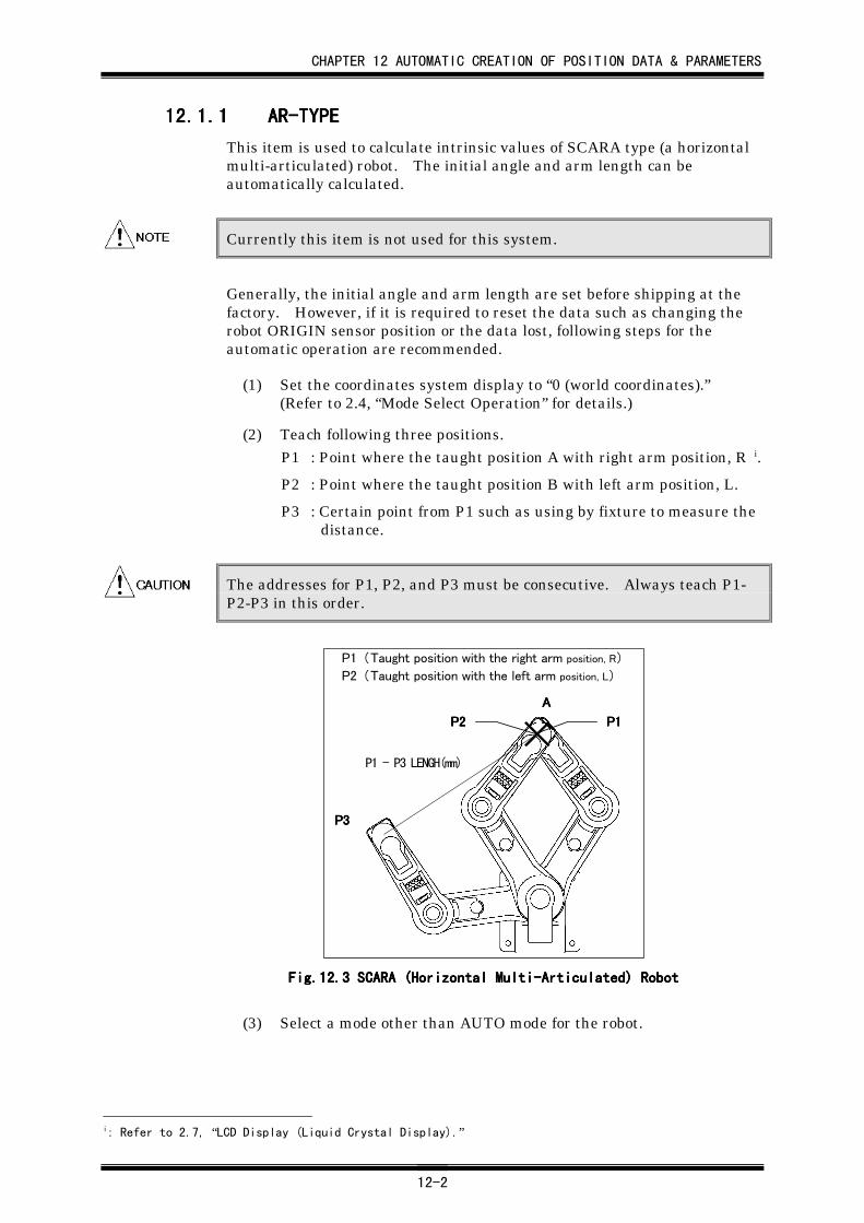
CHAPTER 12 AUTOMATIC CREATION OF POSITION DATA & PARAMETERS
12-2
12.1.112.1.112.1.112.1.1 AR-TYPEAR-TYPEAR-TYPEAR-TYPE
This item is used to calculate intrinsic values of SCARA type (a horizontalmulti-articulated) robot. The initial angle and arm length can beautomatically calculated.
Currently this item is not used for this system.
Generally, the initial angle and arm length are set before shipping at thefactory. However, if it is required to reset the data such as changing therobot ORIGIN sensor position or the data lost, following steps for theautomatic operation are recommended.
(1) Set the coordinates system display to “0 (world coordinates).”(Refer to 2.4, “Mode Select Operation” for details.)
(2) Teach following three positions.P1 : Point where the taught position A with right arm position, R i.
P2 : Point where the taught position B with left arm position, L.
P3 : Certain point from P1 such as using by fixture to measure thedistance.
The addresses for P1, P2, and P3 must be consecutive. Always teach P1-P2-P3 in this order.
P1 (Taught position with the right arm position, R)
P2 (Taught position with the left arm position, L)
AAAA
P3P3P3P3
P1 - P3 LENGH(mm)
P1P1P1P1P2P2P2P2
Fig.12.Fig.12.Fig.12.Fig.12.3333 SCARA (Horizontal Multi-Articulated) Robot SCARA (Horizontal Multi-Articulated) Robot SCARA (Horizontal Multi-Articulated) Robot SCARA (Horizontal Multi-Articulated) Robot
(3) Select a mode other than AUTO mode for the robot.
i: Refer to 2.7, “LCD Display (Liquid Crystal Display).”
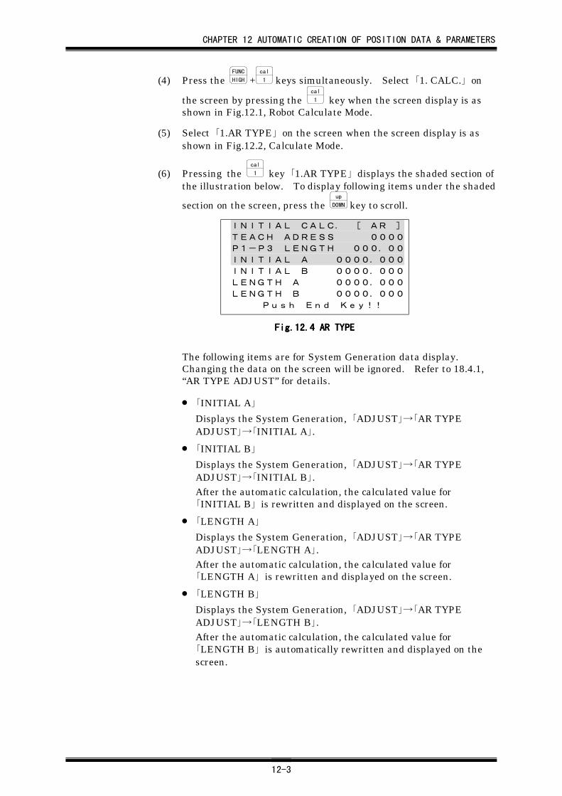
CHAPTER 12 AUTOMATIC CREATION OF POSITION DATA & PARAMETERS
12-3
(4) Press the FUNC
HIGH +cal
1 keys simultaneously. Select 「1. CALC.」 on
the screen by pressing the cal
1 key when the screen display is asshown in Fig.12.1, Robot Calculate Mode.
(5) Select 「1.AR TYPE」 on the screen when the screen display is asshown in Fig.12.2, Calculate Mode.
(6) Pressing the cal
1 key 「1.AR TYPE」 displays the shaded section ofthe illustration below. To display following items under the shaded
section on the screen, press the up
DOWN key to scroll.
INITIAL CALC. [ AR ]
TEACH ADRESS 0000
P1-P3 LENGTH 000.00
INITIAL A 0000.000
INITIAL B 0000.000
LENGTH A 0000.000
LENGTH B 0000.000
Push End Key!!
Fig.12.Fig.12.Fig.12.Fig.12.4444 AR TYPE AR TYPE AR TYPE AR TYPE
The following items are for System Generation data display.Changing the data on the screen will be ignored. Refer to 18.4.1,“AR TYPE ADJUST” for details.
• 「INITIAL A」
Displays the System Generation, 「ADJUST」→「AR TYPEADJUST」→「INITIAL A」.
• 「INITIAL B」
Displays the System Generation, 「ADJUST」→「AR TYPEADJUST」→「INITIAL B」.After the automatic calculation, the calculated value for「INITIAL B」 is rewritten and displayed on the screen.
• 「LENGTH A」
Displays the System Generation, 「ADJUST」→「AR TYPEADJUST」→「LENGTH A」.After the automatic calculation, the calculated value for「LENGTH A」 is rewritten and displayed on the screen.
• 「LENGTH B」
Displays the System Generation, 「ADJUST」→「AR TYPEADJUST」→「LENGTH B」.After the automatic calculation, the calculated value for「LENGTH B」 is automatically rewritten and displayed on thescreen.
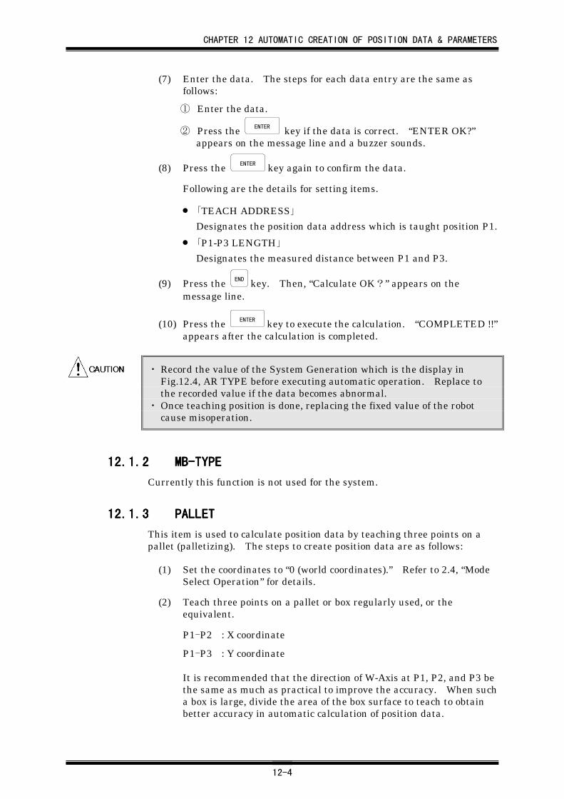
CHAPTER 12 AUTOMATIC CREATION OF POSITION DATA & PARAMETERS
12-4
(7) Enter the data. The steps for each data entry are the same asfollows:
① Enter the data.
② Press the ENTER key if the data is correct. “ENTER OK?”
appears on the message line and a buzzer sounds.
(8) Press the ENTER key again to confirm the data.
Following are the details for setting items.
• 「TEACH ADDRESS」
Designates the position data address which is taught position P1.
• 「P1-P3 LENGTH」
Designates the measured distance between P1 and P3.
(9) Press the END key. Then, “Calculate OK?” appears on themessage line.
(10) Press the ENTER key to execute the calculation. “COMPLETED !!”appears after the calculation is completed.
・ Record the value of the System Generation which is the display inFig.12.4, AR TYPE before executing automatic operation. Replace tothe recorded value if the data becomes abnormal.
・ Once teaching position is done, replacing the fixed value of the robotcause misoperation.
12.1.212.1.212.1.212.1.2 MB-TYPEMB-TYPEMB-TYPEMB-TYPE
Currently this function is not used for the system.
12.1.312.1.312.1.312.1.3 PALLETPALLETPALLETPALLET
This item is used to calculate position data by teaching three points on apallet (palletizing). The steps to create position data are as follows:
(1) Set the coordinates to “0 (world coordinates).” Refer to 2.4, “ModeSelect Operation” for details.
(2) Teach three points on a pallet or box regularly used, or theequivalent.
P1-P2 : X coordinate
P1-P3 : Y coordinate
It is recommended that the direction of W-Axis at P1, P2, and P3 bethe same as much as practical to improve the accuracy. When sucha box is large, divide the area of the box surface to teach to obtainbetter accuracy in automatic calculation of position data.
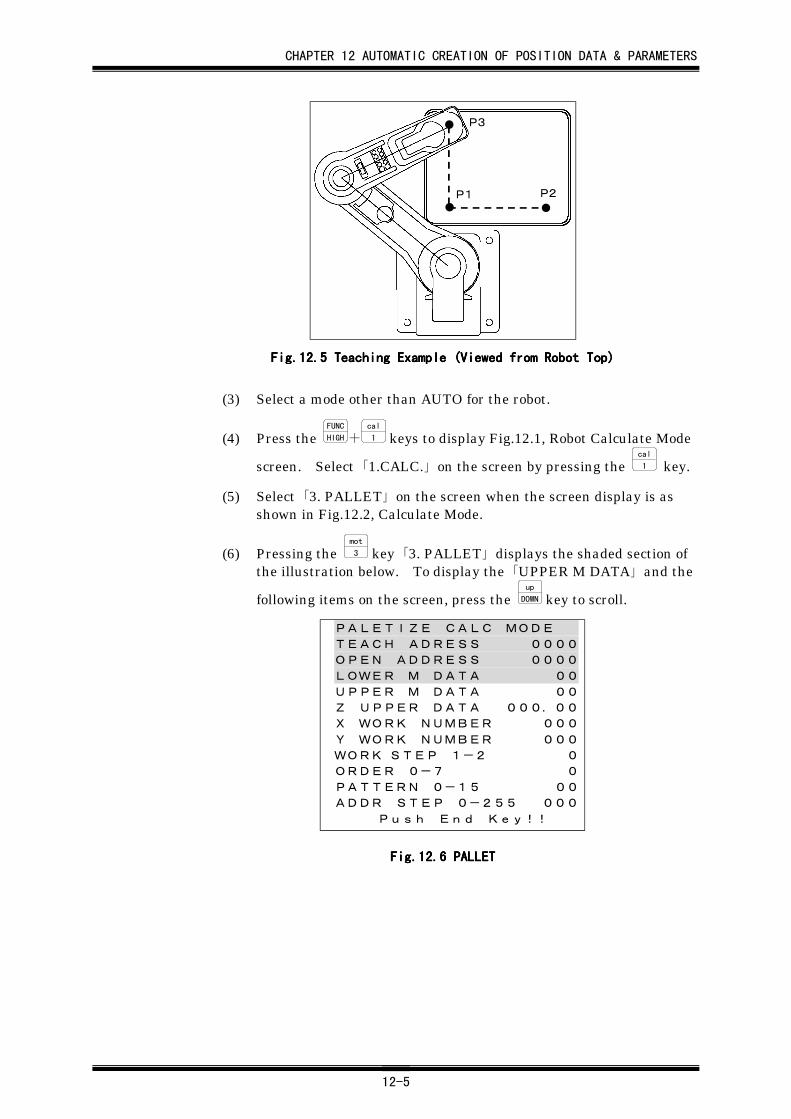
CHAPTER 12 AUTOMATIC CREATION OF POSITION DATA & PARAMETERS
12-5
P3
P1 P2
Fig.12.Fig.12.Fig.12.Fig.12.5555 Teaching Example (Viewed from Robot Top) Teaching Example (Viewed from Robot Top) Teaching Example (Viewed from Robot Top) Teaching Example (Viewed from Robot Top)
(3) Select a mode other than AUTO for the robot.
(4) Press the FUNC
HIGH+cal
1 keys to display Fig.12.1, Robot Calculate Mode
screen. Select 「1.CALC.」 on the screen by pressing the cal
1 key.
(5) Select 「3. PALLET」 on the screen when the screen display is asshown in Fig.12.2, Calculate Mode.
(6) Pressing the mot
3 key 「3. PALLET」 displays the shaded section ofthe illustration below. To display the 「UPPER M DATA」 and the
following items on the screen, press the up
DOWN key to scroll.
PALETIZE CALC MODE
TEACH ADRESS 0000
OPEN ADDRESS 0000
LOWER M DATA 00
UPPER M DATA 00
Z UPPER DATA 000.00
X WORK NUMBER 000
Y WORK NUMBER 000
WORK STEP 1-2 0
ORDER 0-7 0
PATTERN 0-15 00
ADDR STEP 0-255 000
Push End Key!!
Fig.12.Fig.12.Fig.12.Fig.12.6666 PALLET PALLET PALLET PALLET
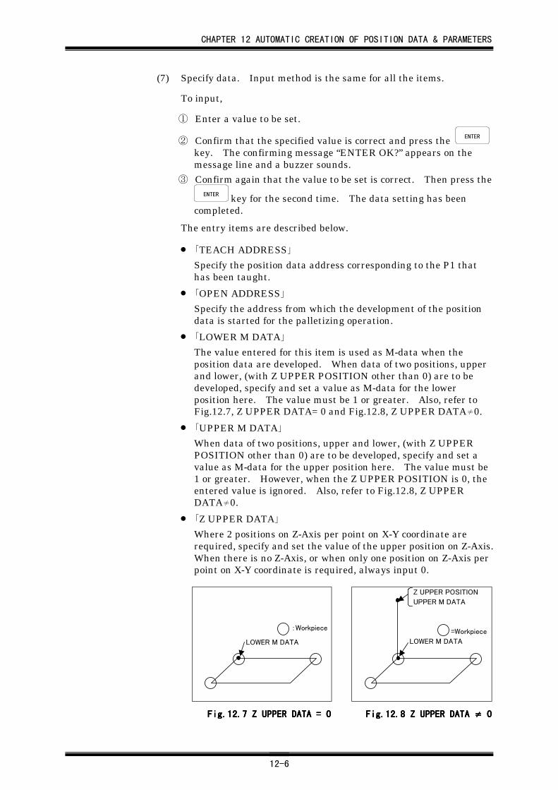
CHAPTER 12 AUTOMATIC CREATION OF POSITION DATA & PARAMETERS
12-6
(7) Specify data. Input method is the same for all the items.
To input,
① Enter a value to be set.
② Confirm that the specified value is correct and press the ENTER
key. The confirming message “ENTER OK?” appears on themessage line and a buzzer sounds.
③ Confirm again that the value to be set is correct. Then press theENTER key for the second time. The data setting has been
completed.
The entry items are described below.
• 「TEACH ADDRESS」
Specify the position data address corresponding to the P1 thathas been taught.
• 「OPEN ADDRESS」
Specify the address from which the development of the positiondata is started for the palletizing operation.
• 「LOWER M DATA」
The value entered for this item is used as M-data when theposition data are developed. When data of two positions, upperand lower, (with Z UPPER POSITION other than 0) are to bedeveloped, specify and set a value as M-data for the lowerposition here. The value must be 1 or greater. Also, refer toFig.12.7, Z UPPER DATA= 0 and Fig.12.8, Z UPPER DATA≠0.
• 「UPPER M DATA」
When data of two positions, upper and lower, (with Z UPPERPOSITION other than 0) are to be developed, specify and set avalue as M-data for the upper position here. The value must be1 or greater. However, when the Z UPPER POSITION is 0, theentered value is ignored. Also, refer to Fig.12.8, Z UPPERDATA≠0.
• 「Z UPPER DATA」
Where 2 positions on Z-Axis per point on X-Y coordinate arerequired, specify and set the value of the upper position on Z-Axis.When there is no Z-Axis, or when only one position on Z-Axis perpoint on X-Y coordinate is required, always input 0.
:Workpiece
LOWER M DATA
Z UPPER POSITION
UPPER M DATA
=Workpiece
LOWER M DATA
Fig.12.Fig.12.Fig.12.Fig.12.7777 Z UPPER DATA = 0 Z UPPER DATA = 0 Z UPPER DATA = 0 Z UPPER DATA = 0 Fig.12.Fig.12.Fig.12.Fig.12.8888 Z UPPER DATA Z UPPER DATA Z UPPER DATA Z UPPER DATA ≠≠≠≠ 0 0 0 0
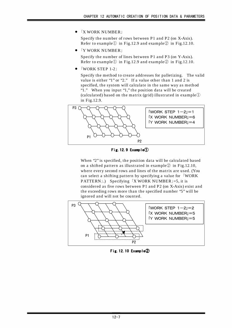
CHAPTER 12 AUTOMATIC CREATION OF POSITION DATA & PARAMETERS
12-7
• 「X WORK NUMBER」
Specify the number of rows between P1 and P2 (on X-Axis).Refer to example① in Fig.12.9 and example② in Fig.12.10.
• 「Y WORK NUMBER」
Specify the number of lines between P1 and P3 (on Y-Axis).Refer to example① in Fig.12.9 and example② in Fig.12.10.
• 「WORK STEP 1-2」
Specify the method to create addresses for palletizing. The validvalue is either “1” or “2.” If a value other than 1 and 2 isspecified, the system will calculate in the same way as method“1.” When you input “1,” the position data will be created(calculated) based on the matrix (grid) illustrated in example①in Fig.12.9.
P3
P2P1
「WORK STEP 1-2」=1「X WORK NUMBER」=6「Y WORK NUMBER」=4
Fig.12.Fig.12.Fig.12.Fig.12.9999 Example Example Example Example①①①①
When “2” is specified, the position data will be calculated basedon a shifted pattern as illustrated in example② in Fig.12.10,where every second rows and lines of the matrix are used. (Youcan select a shifting pattern by specifying a value for 「WORKPATTERN」.) Specifying 「X WORK NUMBER」=5, it isconsidered as five rows between P1 and P2 (on X-Axis) exist andthe exceeding rows more than the specified number “5” will beignored and will not be counted.
P2
P1
P3「WORK STEP 1-2」=2「X WORK NUMBER」=5「Y WORK NUMBER」=5
Fig.12.Fig.12.Fig.12.Fig.12.10101010 Example Example Example Example②②②②
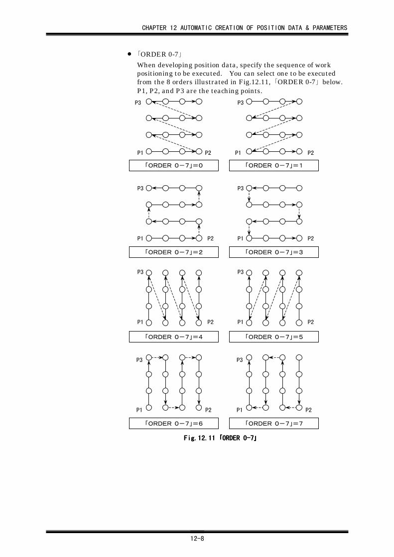
CHAPTER 12 AUTOMATIC CREATION OF POSITION DATA & PARAMETERS
12-8
• 「ORDER 0-7」
When developing position data, specify the sequence of workpositioning to be executed. You can select one to be executedfrom the 8 orders illustrated in Fig.12.11, 「ORDER 0-7」 below.P1, P2, and P3 are the teaching points.
P1 P2
P3
P1 P2
P3
P1 P2
P3
P1 P2
P3
P1 P2
P3
P1 P2
P3
P1 P2
P3
P1 P2
P3
「ORDER 0-7」=0 「ORDER 0-7」=1
「ORDER 0-7」=2 「ORDER 0-7」=3
「ORDER 0-7」=4 「ORDER 0-7」=5
「ORDER 0-7」=6 「ORDER 0-7」=7
Fig.12.Fig.12.Fig.12.Fig.12.11111111 「「「「ORDER 0-7ORDER 0-7ORDER 0-7ORDER 0-7」」」」
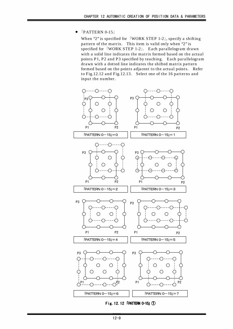
CHAPTER 12 AUTOMATIC CREATION OF POSITION DATA & PARAMETERS
12-9
• 「PATTERN 0-15」
When “2” is specified for 「WORK STEP 1-2」, specify a shiftingpattern of the matrix. This item is valid only when “2” isspecified for 「WORK STEP 1-2」. Each parallelogram drawnwith a solid line indicates the matrix formed based on the actualpoints P1, P2 and P3 specified by teaching. Each parallelogramdrawn with a dotted line indicates the shifted matrix patternformed based on the points adjacent to the actual points. Referto Fig.12.12 and Fig.12.13. Select one of the 16 patterns andinput the number.
「PATTERN 0-15」=0 「PATTERN 0-15」=1
P1 P2
P3
P1 P2
P3
「PATTERN 0-15」=2 「PATTERN 0-15」=3
P1 P2
P3
P1 P2
P3
「PATTERN 0-15」=4 「PATTERN 0-15」=5
P1 P2
P3
P1 P2
P3
「PATTERN 0-15」=6 「PATTERN 0-15」=7
P1 P2
P3
P1 P2
P3
Fig.12.Fig.12.Fig.12.Fig.12.12121212 「「「「PATTERN 0-15PATTERN 0-15PATTERN 0-15PATTERN 0-15」」」」 ①①①①
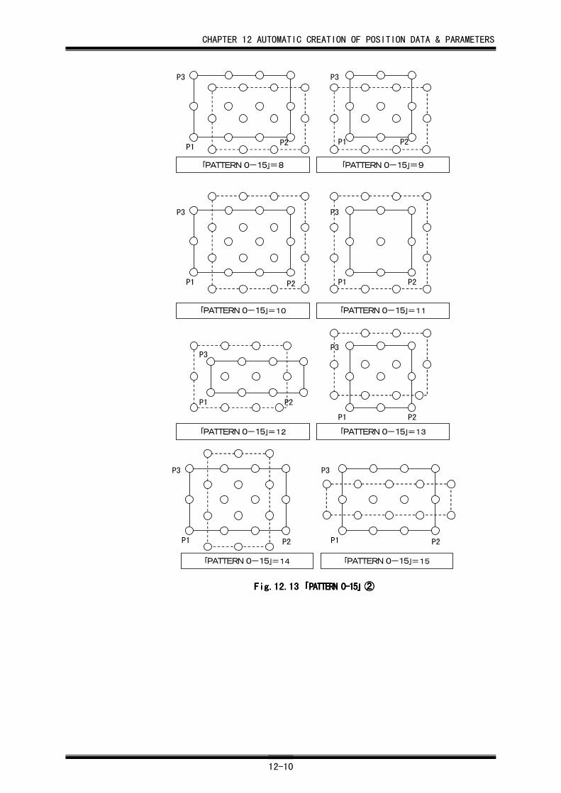
CHAPTER 12 AUTOMATIC CREATION OF POSITION DATA & PARAMETERS
12-10
P1P2
P3
P1 P2
P3
P1 P2
P3
P1 P2
P3
P1 P2
P3
P1 P2
P3
P1 P2
P3
P1 P2
P3
「PATTERN 0-15」=8 「PATTERN 0-15」=9
「PATTERN 0-15」=10 「PATTERN 0-15」=11
「PATTERN 0-15」=12 「PATTERN 0-15」=13
「PATTERN 0-15」=14 「PATTERN 0-15」=15
Fig.12.Fig.12.Fig.12.Fig.12.13131313 「「「「PATTERN 0-15PATTERN 0-15PATTERN 0-15PATTERN 0-15」」」」 ②②②②
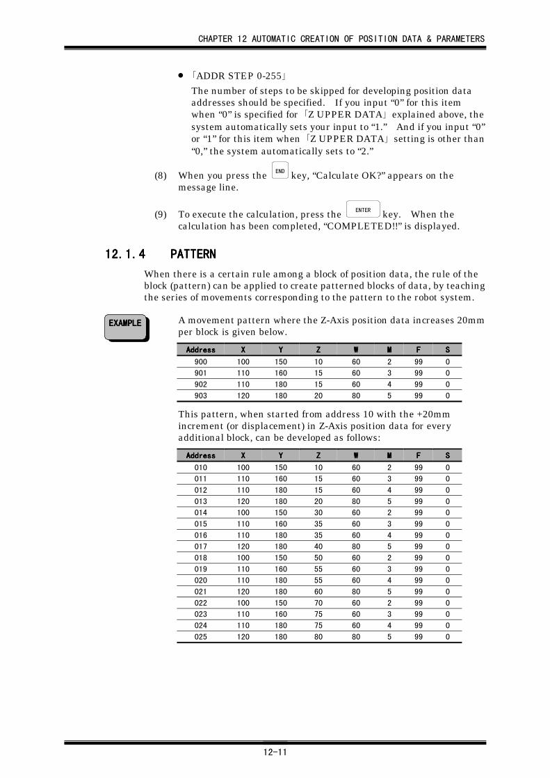
CHAPTER 12 AUTOMATIC CREATION OF POSITION DATA & PARAMETERS
12-11
• 「ADDR STEP 0-255」
The number of steps to be skipped for developing position dataaddresses should be specified. If you input “0” for this itemwhen “0” is specified for 「Z UPPER DATA」 explained above, thesystem automatically sets your input to “1.” And if you input “0”or “1” for this item when 「Z UPPER DATA」 setting is other than“0,” the system automatically sets to “2.”
(8) When you press the END key, “Calculate OK?” appears on themessage line.
(9) To execute the calculation, press the ENTER key. When thecalculation has been completed, “COMPLETED!!” is displayed.
12.1.412.1.412.1.412.1.4 PATTERNPATTERNPATTERNPATTERN
When there is a certain rule among a block of position data, the rule of theblock (pattern) can be applied to create patterned blocks of data, by teachingthe series of movements corresponding to the pattern to the robot system.
A movement pattern where the Z-Axis position data increases 20mmper block is given below.
AddressAddressAddressAddress XXXX YYYY ZZZZ WWWW MMMM FFFF SSSS
900 100 150 10 60 2 99 0
901 110 160 15 60 3 99 0
902 110 180 15 60 4 99 0
903 120 180 20 80 5 99 0
This pattern, when started from address 10 with the +20mmincrement (or displacement) in Z-Axis position data for everyadditional block, can be developed as follows:
AddressAddressAddressAddress XXXX YYYY ZZZZ WWWW MMMM FFFF SSSS
010 100 150 10 60 2 99 0
011 110 160 15 60 3 99 0
012 110 180 15 60 4 99 0
013 120 180 20 80 5 99 0
014 100 150 30 60 2 99 0
015 110 160 35 60 3 99 0
016 110 180 35 60 4 99 0
017 120 180 40 80 5 99 0
018 100 150 50 60 2 99 0
019 110 160 55 60 3 99 0
020 110 180 55 60 4 99 0
021 120 180 60 80 5 99 0
022 100 150 70 60 2 99 0
023 110 160 75 60 3 99 0
024 110 180 75 60 4 99 0
025 120 180 80 80 5 99 0
EXAMPLEEXAMPLEEXAMPLEEXAMPLE
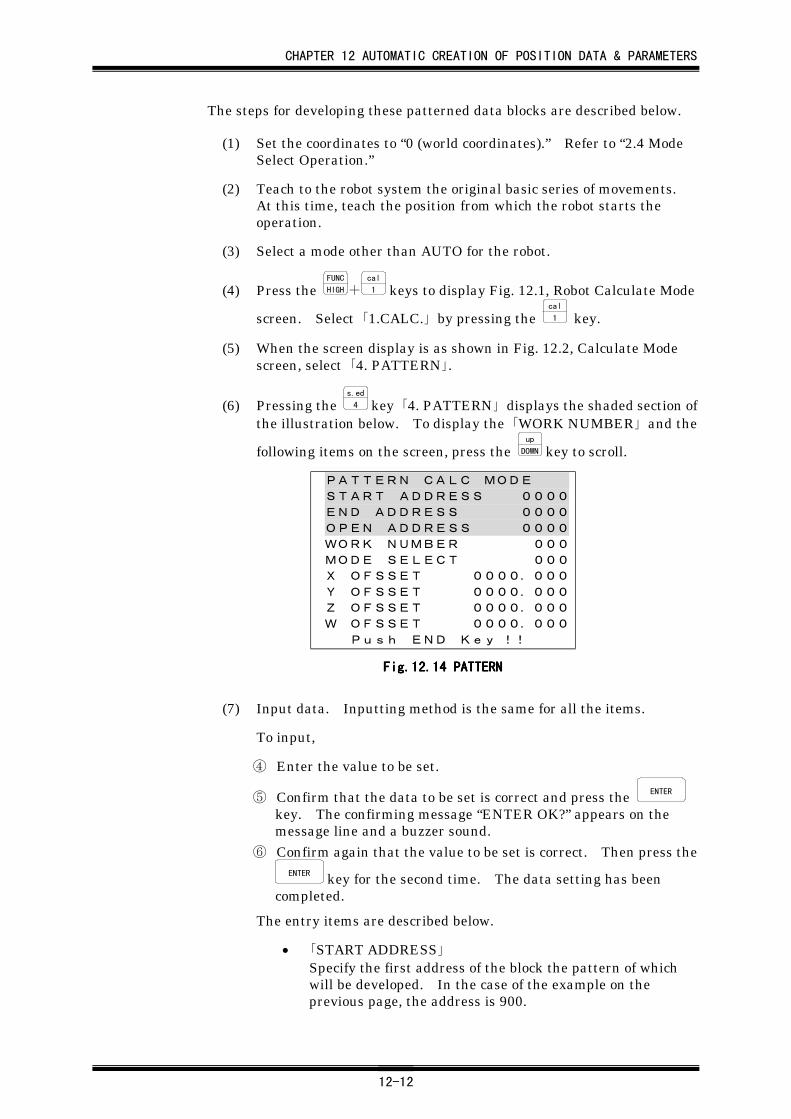
CHAPTER 12 AUTOMATIC CREATION OF POSITION DATA & PARAMETERS
12-12
The steps for developing these patterned data blocks are described below.
(1) Set the coordinates to “0 (world coordinates).” Refer to “2.4 ModeSelect Operation.”
(2) Teach to the robot system the original basic series of movements.At this time, teach the position from which the robot starts theoperation.
(3) Select a mode other than AUTO for the robot.
(4) Press the FUNC
HIGH+cal
1 keys to display Fig. 12.1, Robot Calculate Mode
screen. Select 「1.CALC.」 by pressing the cal
1 key.
(5) When the screen display is as shown in Fig. 12.2, Calculate Modescreen, select 「4. PATTERN」.
(6) Pressing the s.ed
4 key 「4. PATTERN」 displays the shaded section ofthe illustration below. To display the 「WORK NUMBER」 and the
following items on the screen, press the up
DOWN key to scroll.
PATTERN CALC MODE
START ADDRESS 0000
END ADDRESS 0000
OPEN ADDRESS 0000
WORK NUMBER 000
MODE SELECT 000
X OFSSET 0000.000
Y OFSSET 0000.000
Z OFSSET 0000.000
W OFSSET 0000.000
Push END Key !!
Fig.12.Fig.12.Fig.12.Fig.12.14141414 PATTERN PATTERN PATTERN PATTERN
(7) Input data. Inputting method is the same for all the items.
To input,
④ Enter the value to be set.
⑤ Confirm that the data to be set is correct and press the ENTER
key. The confirming message “ENTER OK?” appears on themessage line and a buzzer sound.
⑥ Confirm again that the value to be set is correct. Then press theENTER key for the second time. The data setting has been
completed.
The entry items are described below.
• 「START ADDRESS」Specify the first address of the block the pattern of whichwill be developed. In the case of the example on theprevious page, the address is 900.
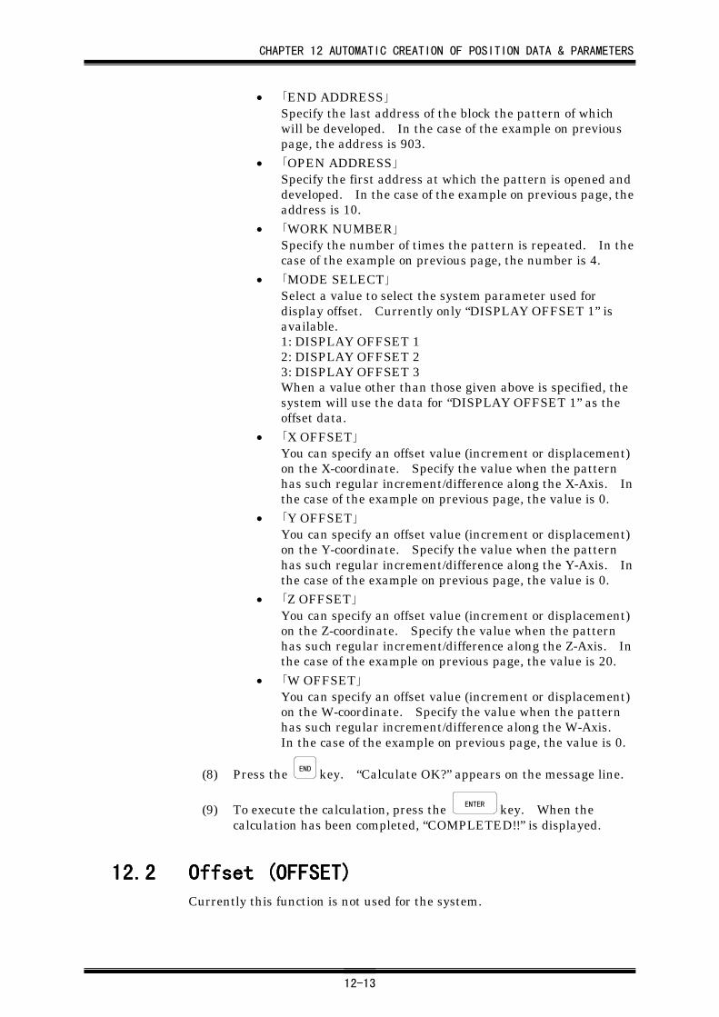
CHAPTER 12 AUTOMATIC CREATION OF POSITION DATA & PARAMETERS
12-13
• 「END ADDRESS」Specify the last address of the block the pattern of whichwill be developed. In the case of the example on previouspage, the address is 903.
• 「OPEN ADDRESS」Specify the first address at which the pattern is opened anddeveloped. In the case of the example on previous page, theaddress is 10.
• 「WORK NUMBER」Specify the number of times the pattern is repeated. In thecase of the example on previous page, the number is 4.
• 「MODE SELECT」Select a value to select the system parameter used fordisplay offset. Currently only “DISPLAY OFFSET 1” isavailable.1: DISPLAY OFFSET 12: DISPLAY OFFSET 23: DISPLAY OFFSET 3When a value other than those given above is specified, thesystem will use the data for “DISPLAY OFFSET 1” as theoffset data.
• 「X OFFSET」You can specify an offset value (increment or displacement)on the X-coordinate. Specify the value when the patternhas such regular increment/difference along the X-Axis. Inthe case of the example on previous page, the value is 0.
• 「Y OFFSET」You can specify an offset value (increment or displacement)on the Y-coordinate. Specify the value when the patternhas such regular increment/difference along the Y-Axis. Inthe case of the example on previous page, the value is 0.
• 「Z OFFSET」You can specify an offset value (increment or displacement)on the Z-coordinate. Specify the value when the patternhas such regular increment/difference along the Z-Axis. Inthe case of the example on previous page, the value is 20.
• 「W OFFSET」You can specify an offset value (increment or displacement)on the W-coordinate. Specify the value when the patternhas such regular increment/difference along the W-Axis.In the case of the example on previous page, the value is 0.
(8) Press the END key. “Calculate OK?” appears on the message line.
(9) To execute the calculation, press the ENTER key. When thecalculation has been completed, “COMPLETED!!” is displayed.
12.212.212.212.2 Offset (OFFSET)Offset (OFFSET)Offset (OFFSET)Offset (OFFSET)Currently this function is not used for the system.
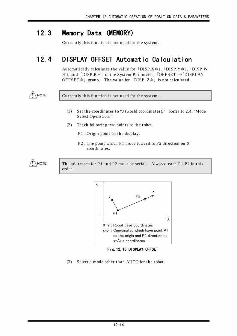
CHAPTER 12 AUTOMATIC CREATION OF POSITION DATA & PARAMETERS
12-14
12.312.312.312.3 Memory Data (MEMORY)Memory Data (MEMORY)Memory Data (MEMORY)Memory Data (MEMORY)Currently this function is not used for the system.
12.412.412.412.4 DISPLAY OFFSET Automatic CalculationDISPLAY OFFSET Automatic CalculationDISPLAY OFFSET Automatic CalculationDISPLAY OFFSET Automatic CalculationAutomatically calculates the value for 「DISP.X*」, 「DISP.Y*」, 「DISP.W*」, and 「DISP.R*」 of the System Parameter, 「OFFSET」→「DISPLAYOFFSET*」 group. The value for 「DISP. Z*」 is not calculated.
Currently this function is not used for the system.
(1) Set the coordinates to “0 (world coordinates).” Refer to 2.4, “ModeSelect Operation.”
(2) Teach following two points to the robot.
P1 : Origin point on the display.
P2 : The point which P1 move toward to P2 direction on Xcoordinates.
The addresses for P1 and P2 must be serial. Always teach P1-P2 in thisorder.
Y
P1
X
y
x
P2
X-Y : Robot base coordinates
x-y : Coordinates which have point P1
as the origin and P2 direction as
x-Axis coordinates.
Fig.12.Fig.12.Fig.12.Fig.12.15151515 DISPLAY OFFSET DISPLAY OFFSET DISPLAY OFFSET DISPLAY OFFSET
(3) Select a mode other than AUTO for the robot.
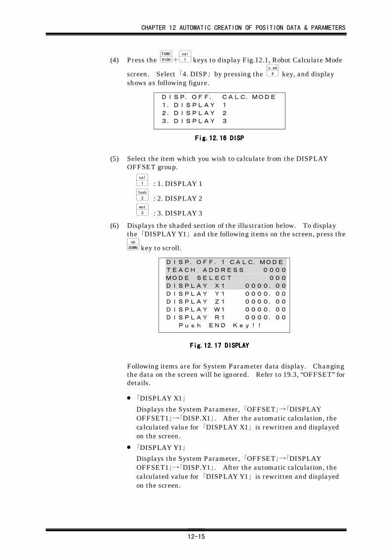
CHAPTER 12 AUTOMATIC CREATION OF POSITION DATA & PARAMETERS
12-15
(4) Press the FUNC
HIGH+cal
1 keys to display Fig.12.1, Robot Calculate Mode
screen. Select 「4. DISP」 by pressing the s.ed
4 key, and displayshows as following figure.
DISP.OFF. CALC.MODE1.DISPLAY 12.DISPLAY 23.DISPLAY 3
Fig.12.Fig.12.Fig.12.Fig.12.16161616 DISP DISP DISP DISP
(5) Select the item which you wish to calculate from the DISPLAYOFFSET group.
cal
1 : 1. DISPLAY 1task
2 : 2. DISPLAY 2mot
3 : 3. DISPLAY 3
(6) Displays the shaded section of the illustration below. To displaythe 「DISPLAY Y1」 and the following items on the screen, press theup
DOWN key to scroll.
DISP.OFF.1 CALC.MODETEACH ADDRESS 0000MODE SELECT 000DISPLAY X1 0000.00DISPLAY Y1 0000.00DISPLAY Z1 0000.00DISPLAY W1 0000.00DISPLAY R1 0000.00 Push END Key!!
Fig.12.Fig.12.Fig.12.Fig.12.17171717 DISPLAY DISPLAY DISPLAY DISPLAY
Following items are for System Parameter data display. Changingthe data on the screen will be ignored. Refer to 19.3, “OFFSET” fordetails.
• 「DISPLAY X1」
Displays the System Parameter, 「OFFSET」→「DISPLAYOFFSET1」→「DISP.X1」. After the automatic calculation, thecalculated value for 「DISPLAY X1」 is rewritten and displayedon the screen.
• 「DISPLAY Y1」
Displays the System Parameter, 「OFFSET」→「DISPLAYOFFSET1」→「DISP.Y1」. After the automatic calculation, thecalculated value for 「DISPLAY Y1」 is rewritten and displayedon the screen.
CHAPTER 12 AUTOMATIC CREATION OF POSITION DATA & PARAMETERS
12-16
• 「DISPLAY Z1」
Displays the System Parameter, 「OFFSET」→「DISPLAYOFFSET1」→「DISP.Z1」.
• 「DISPLAY W1」
Displays the System Parameter, 「OFFSET」→「DISPLAYOFFSET1」→「DISP.W1」. After the automatic calculation, thecalculated value for 「DISPLAY W1」 is rewritten and displayedon the screen.
• 「DISPLAY R1」
Displays the System Parameter 「OFFSET」→「DISPLAYOFFSET1」 →「DISP.R1」. After the automatic operation, thecalculated value for 「DISPLAY R1」 is rewritten and displayedon the screen.
(7) Input data. Inputting method is the same for all the items.
To input,
① Enter the value to be set.
② Confirm that the data to be set is correct and press the ENTER
key. The confirming message “ENTER OK?” appears on themessage line and a buzzer sound.
③ Confirm again that the value to be set is correct. Then press theENTER key for the second time. The data setting has been
completed.
The entry items are described below.
• 「TEACH ADDRESS」Specify the position data address for taught position P1.
• 「MODE SELECT」Not used. Specify “0” for this value.
(8) Press the END key. “Calculate OK?” appears on the message line.
(9) To execute the calculation, press the ENTER key. When thecalculation has been completed, “COMPLETED!!” is displayed.
12.512.512.512.5 Setting Servo Parameters (SERVO)Setting Servo Parameters (SERVO)Setting Servo Parameters (SERVO)Setting Servo Parameters (SERVO)Servo parameters are properly adjusted before shipment according to theunit to be controlled. However, if the motor emits abnormal noise orhunting occurs during positioning operation after the shipment, readjustthe parameters. The steps to readjust the parameters are as follows:
(1) Set the coordinates to “0 (world coordinates).” Refer to 2.4, “ModeSelect Operation.”
(2) Press the FUNC
HIGH +cal
1 keys to set the Teach Pendant in KEY-IN mode.
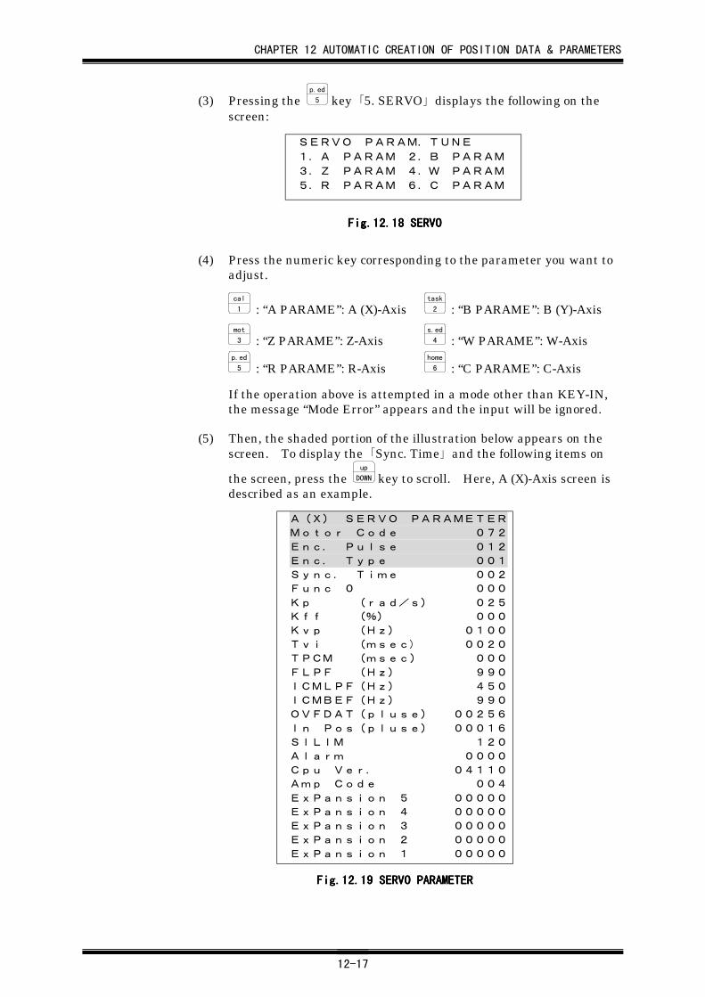
CHAPTER 12 AUTOMATIC CREATION OF POSITION DATA & PARAMETERS
12-17
(3) Pressing the p.ed
5 key 「5. SERVO」 displays the following on thescreen:
SERVO PARAM.TUNE1.A PARAM 2.B PARAM3.Z PARAM 4.W PARAM5.R PARAM 6.C PARAM
Fig.12.Fig.12.Fig.12.Fig.12.18181818 SERVO SERVO SERVO SERVO
(4) Press the numeric key corresponding to the parameter you want toadjust.
cal
1 : “A PARAME”: A (X)-Axistask
2 : “B PARAME”: B (Y)-Axismot
3 : “Z PARAME”: Z-Axiss.ed
4 : “W PARAME”: W-Axisp.ed
5 : “R PARAME”: R-Axishome
6 : “C PARAME”: C-Axis
If the operation above is attempted in a mode other than KEY-IN,the message “Mode Error” appears and the input will be ignored.
(5) Then, the shaded portion of the illustration below appears on thescreen. To display the 「Sync. Time」 and the following items on
the screen, press the up
DOWN key to scroll. Here, A (X)-Axis screen isdescribed as an example.
A(X) SERVO PARAMETER
Motor Code 072
Enc. Pulse 012
Enc. Type 001
Sync. Time 002
Func 0 000
Kp (rad/s) 025
Kff (%) 000
Kvp (Hz) 0100
Tvi (msec) 0020
TPCM (msec) 000
FLPF (Hz) 990
ICMLPF(Hz) 450
ICMBEF(Hz) 990
OVFDAT(pluse) 00256
In Pos(pluse) 00016
SILIM 120
Alarm 0000
Cpu Ver. 04110
Amp Code 004
ExPansion 5 00000
ExPansion 4 00000
ExPansion 3 00000
ExPansion 2 00000
ExPansion 1 00000
Fig.12.Fig.12.Fig.12.Fig.12.19191919 SERVO PARAMETER SERVO PARAMETER SERVO PARAMETER SERVO PARAMETER
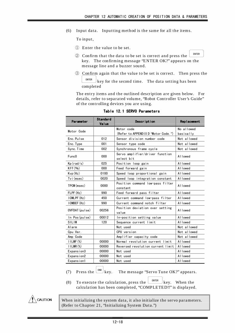
CHAPTER 12 AUTOMATIC CREATION OF POSITION DATA & PARAMETERS
12-18
(6) Input data. Inputting method is the same for all the items.
To input,
① Enter the value to be set.
② Confirm that the data to be set is correct and press the ENTER
key. The confirming message “ENTER OK?” appears on themessage line and a buzzer sound.
③ Confirm again that the value to be set is correct. Then press theENTER key for the second time. The data setting has been
completed
The entry items and the outlined description are given below. Fordetails, refer to separated volume, “Robot Controller User’s Guide”of the controlling devices you are using.
Table 12.Table 12.Table 12.Table 12.1111 SERVO Parameters SERVO Parameters SERVO Parameters SERVO Parameters
ParameterParameterParameterParameterStandardStandardStandardStandard
ValueValueValueValueDescriptionDescriptionDescriptionDescription ReplacementReplacementReplacementReplacement
Motor CodeMotor code
(Refer to APPENDIX D “Motor Code.”)No allowed
basically
Enc.Pulse 012 Sensor division number code Not allowed
Enc.Type 001 Sensor type code Not allowed
Sync.Time 002 Synchronous frame cycle Not allowed
Func0 000Servo amplifier/driver function
select bitAllowed
Kp(rad/s) 025 Position loop gain Allowed
Kff(%) 000 Feed forward gain Allowed
Kvp(Hz) 0100 Speed loop proportional gain Allowed
Tvi(msec) 0020 Speed loop integration constant Allowed
TPCM(msec) 0000Position command low-pass filter
constantAllowed
FLPF(Hz) 990 Feed forward pass filter Allowed
ICMLPF(Hz) 450 Current command low-pass filter Allowed
ICMBEF(Hz) 990 Current command notch filter Allowed
OVFDAT(pulse) 00256Position deviation over setting
valueAllowed
In Pos(pulse) 00012 In-position setting value Allowed
SILIM 120 Sequence current limit Allowed
Alarm Not used Not allowed
Cpu Ver. CPU version Not allowed
Amp Code Amplifier capacity code Not allowed
IILMF(%) 00000 Normal revolution current limit Allowed
IILMR(%) 00000 Reversed revolution current limit Allowed
Expansion3 00000 Not used Allowed
Expansion2 00000 Not used Allowed
Expansion1 00000 Not used Allowed
(7) Press the END key. The message “Servo Tune OK?” appears.
(8) To execute the calculation, press the ENTER key. When thecalculation has been completed, “COMPLETED!!” is displayed.
When initializing the system data, it also initialize the servo parameters.(Refer to Chapter 21, “Initializing System Data.”)
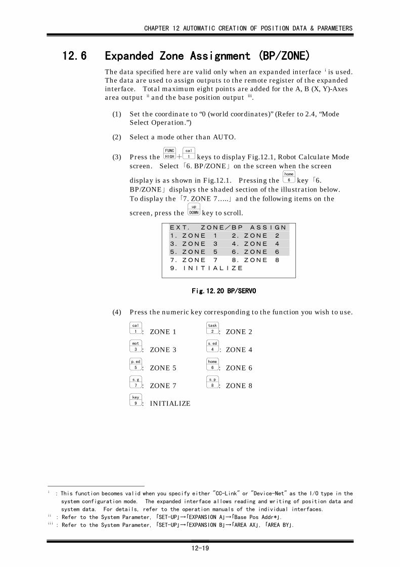
CHAPTER 12 AUTOMATIC CREATION OF POSITION DATA & PARAMETERS
12-19
12.612.612.612.6 Expanded Zone Assignment (BP/ZONE)Expanded Zone Assignment (BP/ZONE)Expanded Zone Assignment (BP/ZONE)Expanded Zone Assignment (BP/ZONE)The data specified here are valid only when an expanded interface i is used.The data are used to assign outputs to the remote register of the expandedinterface. Total maximum eight points are added for the A, B (X, Y)-Axesarea output ii and the base position output iii.
(1) Set the coordinate to “0 (world coordinates)” (Refer to 2.4, “ModeSelect Operation.”)
(2) Select a mode other than AUTO.
(3) Press the FUNC
HIGH+cal
1 keys to display Fig.12.1, Robot Calculate Modescreen. Select 「6. BP/ZONE」 on the screen when the screen
display is as shown in Fig.12.1. Pressing the home
6 key 「6.BP/ZONE」 displays the shaded section of the illustration below.To display the 「7. ZONE 7…..」 and the following items on the
screen, press the up
DOWN key to scroll.
EXT. ZONE/BP ASSIGN1.ZONE 1 2.ZONE 23.ZONE 3 4.ZONE 45.ZONE 5 6.ZONE 67.ZONE 7 8.ZONE 89.INITIALIZE
Fig.12.Fig.12.Fig.12.Fig.12.20202020 BP/SERVO BP/SERVO BP/SERVO BP/SERVO
(4) Press the numeric key corresponding to the function you wish to use.
cal
1 : ZONE 1task
2 : ZONE 2
mot
3 : ZONE 3s.ed
4 : ZONE 4
p.ed
5 : ZONE 5home
6 : ZONE 6s.g
7 : ZONE 7s.p
8 : ZONE 8key
9 : INITIALIZE
i : This function becomes valid when you specify either "CC-Link" or "Device-Net" as the I/O type in the
system configuration mode. The expanded interface allows reading and writing of position data and
system data. For details, refer to the operation manuals of the individual interfaces.ii : Refer to the System Parameter, 「SET-UP」→「EXPANSION A」→「Base Pos Addr*」.iii : Refer to the System Parameter, 「SET-UP」→「EXPANSION B」→「AREA AX」, 「AREA BY」.
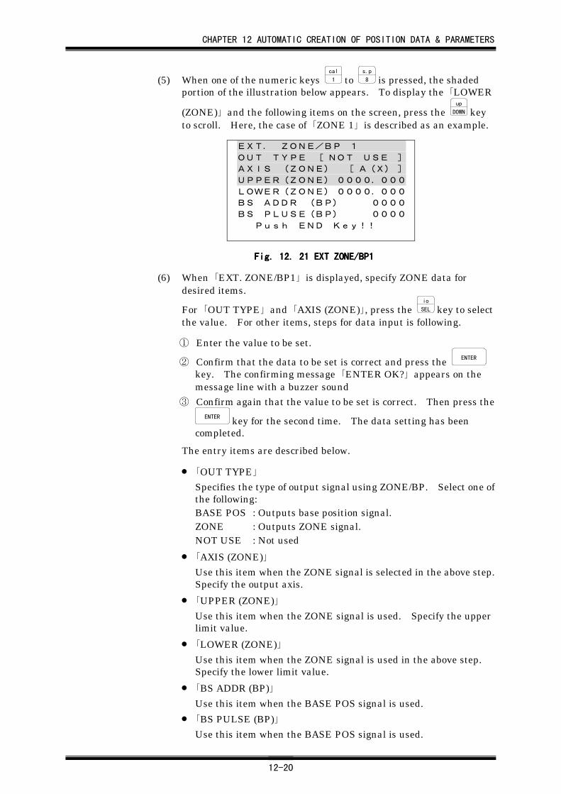
CHAPTER 12 AUTOMATIC CREATION OF POSITION DATA & PARAMETERS
12-20
(5) When one of the numeric keys cal
1 to s.p
8 is pressed, the shadedportion of the illustration below appears. To display the 「LOWER
(ZONE)」 and the following items on the screen, press the up
DOWN keyto scroll. Here, the case of 「ZONE 1」 is described as an example.
EXT. ZONE/BP 1OUT TYPE [ NOT USE ]AXIS (ZONE) [ A(X) ]UPPER(ZONE) 0000.000LOWER(ZONE) 0000.000BS ADDR (BP) 0000BS PLUSE(BP) 0000 Push END Key!!
Fig. 12. Fig. 12. Fig. 12. Fig. 12. 21212121 EXT ZONE/BP1 EXT ZONE/BP1 EXT ZONE/BP1 EXT ZONE/BP1
(6) When 「EXT. ZONE/BP1」 is displayed, specify ZONE data fordesired items.
For 「OUT TYPE」 and 「AXIS (ZONE)」, press the io
SEL key to selectthe value. For other items, steps for data input is following.
① Enter the value to be set.
② Confirm that the data to be set is correct and press the ENTER
key. The confirming message 「ENTER OK?」 appears on themessage line with a buzzer sound
③ Confirm again that the value to be set is correct. Then press theENTER key for the second time. The data setting has been
completed.
The entry items are described below.
• 「OUT TYPE」
Specifies the type of output signal using ZONE/BP. Select one ofthe following:BASE POS : Outputs base position signal.ZONE : Outputs ZONE signal.NOT USE : Not used
• 「AXIS (ZONE)」
Use this item when the ZONE signal is selected in the above step.Specify the output axis.
• 「UPPER (ZONE)」
Use this item when the ZONE signal is used. Specify the upperlimit value.
• 「LOWER (ZONE)」
Use this item when the ZONE signal is used in the above step.Specify the lower limit value.
• 「BS ADDR (BP)」
Use this item when the BASE POS signal is used.
• 「BS PULSE (BP)」
Use this item when the BASE POS signal is used.
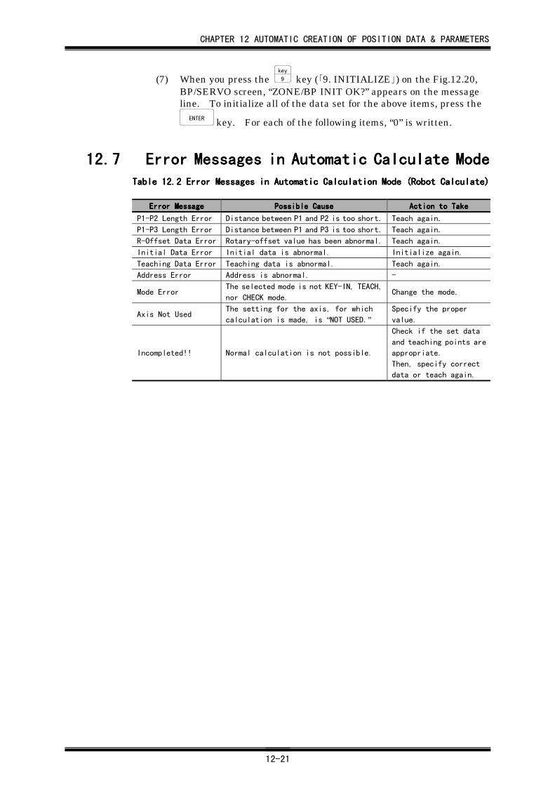
CHAPTER 12 AUTOMATIC CREATION OF POSITION DATA & PARAMETERS
12-21
(7) When you press the key
9 key (「9. INITIALIZE」) on the Fig.12.20,BP/SERVO screen, “ZONE/BP INIT OK?” appears on the messageline. To initialize all of the data set for the above items, press the
ENTER key. For each of the following items, “0” is written.
12.712.712.712.7 Error Messages in Automatic Calculate ModeError Messages in Automatic Calculate ModeError Messages in Automatic Calculate ModeError Messages in Automatic Calculate ModeTable 12.Table 12.Table 12.Table 12.2222 Error Messages in Automatic Calculation Mode (Robot Calculate) Error Messages in Automatic Calculation Mode (Robot Calculate) Error Messages in Automatic Calculation Mode (Robot Calculate) Error Messages in Automatic Calculation Mode (Robot Calculate)
Error MessageError MessageError MessageError Message Possible CausePossible CausePossible CausePossible Cause Action to TakeAction to TakeAction to TakeAction to Take
P1-P2 Length Error Distance between P1 and P2 is too short. Teach again.
P1-P3 Length Error Distance between P1 and P3 is too short. Teach again.
R-Offset Data Error Rotary-offset value has been abnormal. Teach again.
Initial Data Error Initial data is abnormal. Initialize again.
Teaching Data Error Teaching data is abnormal. Teach again.
Address Error Address is abnormal. -
Mode ErrorThe selected mode is not KEY-IN, TEACH,
nor CHECK mode.Change the mode.
Axis Not UsedThe setting for the axis, for which
calculation is made, is “NOT USED.”Specify the proper
value.
Incompleted!! Normal calculation is not possible.
Check if the set data
and teaching points are
appropriate.
Then, specify correct
data or teach again.
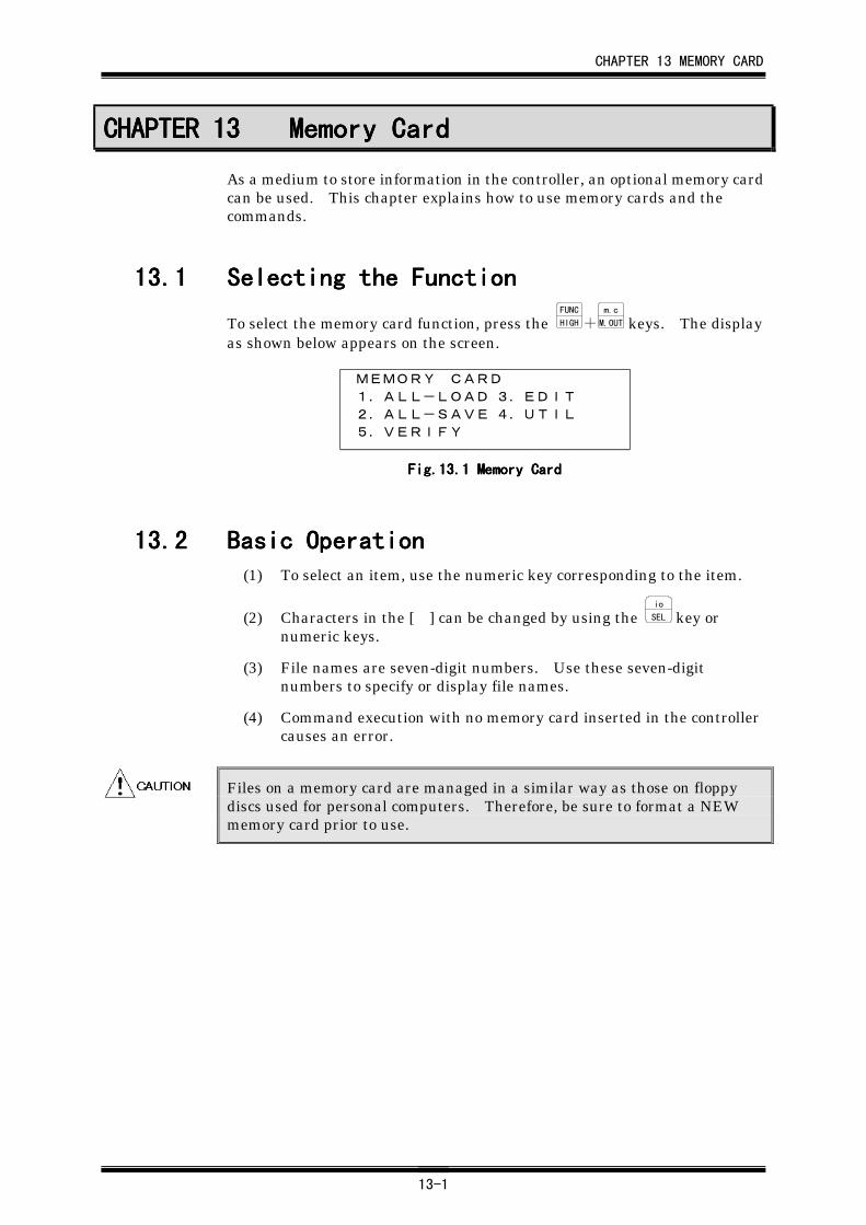
CHAPTER 13 MEMORY CARD
13-1
CHAPTER 13CHAPTER 13CHAPTER 13CHAPTER 13 Memory CardMemory CardMemory CardMemory Card
As a medium to store information in the controller, an optional memory cardcan be used. This chapter explains how to use memory cards and thecommands.
13.113.113.113.1 Selecting the FunctionSelecting the FunctionSelecting the FunctionSelecting the Function
To select the memory card function, press the FUNC
HIGH+m.c
M.OUT keys. The displayas shown below appears on the screen.
MEMORY CARD
1.ALL-LOAD 3.EDIT2.ALL-SAVE 4.UTIL5.VERIFY
Fig.13.Fig.13.Fig.13.Fig.13.1111 Memory Card Memory Card Memory Card Memory Card
13.213.213.213.2 Basic OperationBasic OperationBasic OperationBasic Operation(1) To select an item, use the numeric key corresponding to the item.
(2) Characters in the [ ] can be changed by using the io
SEL key ornumeric keys.
(3) File names are seven-digit numbers. Use these seven-digitnumbers to specify or display file names.
(4) Command execution with no memory card inserted in the controllercauses an error.
Files on a memory card are managed in a similar way as those on floppydiscs used for personal computers. Therefore, be sure to format a NEWmemory card prior to use.
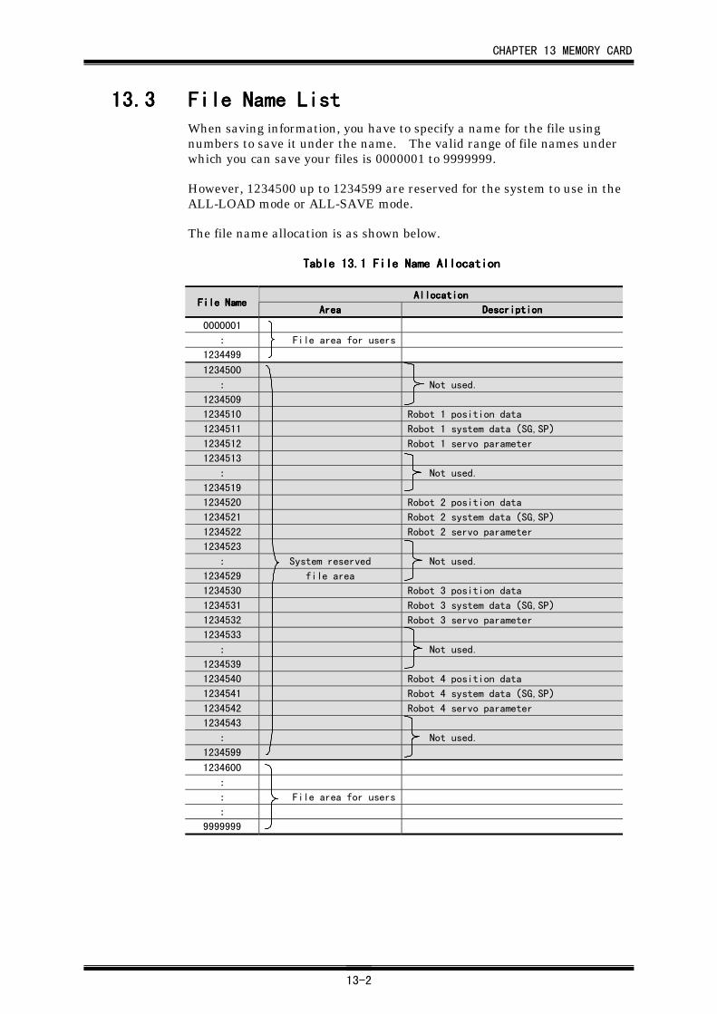
CHAPTER 13 MEMORY CARD
13-2
13.313.313.313.3 File Name ListFile Name ListFile Name ListFile Name ListWhen saving information, you have to specify a name for the file usingnumbers to save it under the name. The valid range of file names underwhich you can save your files is 0000001 to 9999999.
However, 1234500 up to 1234599 are reserved for the system to use in theALL-LOAD mode or ALL-SAVE mode.
The file name allocation is as shown below.
Table 13.Table 13.Table 13.Table 13.1111 File Name Allocation File Name Allocation File Name Allocation File Name Allocation
AllocationAllocationAllocationAllocationFile NameFile NameFile NameFile Name
AreaAreaAreaArea DescriptionDescriptionDescriptionDescription
0000001
: File area for users
1234499
1234500
: Not used.
1234509
1234510 Robot 1 position data
1234511 Robot 1 system data(SG,SP)
1234512 Robot 1 servo parameter
1234513
: Not used.
1234519
1234520 Robot 2 position data
1234521 Robot 2 system data(SG,SP)
1234522 Robot 2 servo parameter
1234523
: System reserved Not used.
1234529 file area
1234530 Robot 3 position data
1234531 Robot 3 system data(SG,SP)
1234532 Robot 3 servo parameter
1234533
: Not used.
1234539
1234540 Robot 4 position data
1234541 Robot 4 system data(SG,SP)
1234542 Robot 4 servo parameter
1234543
: Not used.
1234599
1234600
:
: File area for users
:
9999999
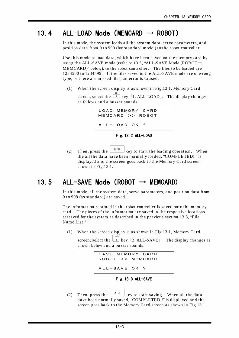
CHAPTER 13 MEMORY CARD
13-3
13.413.413.413.4 ALL-LOAD ModeALL-LOAD ModeALL-LOAD ModeALL-LOAD Mode((((MEMCARD MEMCARD MEMCARD MEMCARD →→→→ ROBOT ROBOT ROBOT ROBOT))))In this mode, the system loads all the system data, servo parameters, andposition data from 0 to 999 (for standard model) to the robot controller.
Use this mode to load data, which have been saved on the memory card byusing the ALL-SAVE mode (refer to 13.5, “ALL-SAVE Mode (ROBOT→MEMCARD)” below), to the robot controller. The files to be loaded are1234500 to 1234599. If the files saved in the ALL-SAVE mode are of wrongtype, or there are missed files, an error is caused.
(1) When the screen display is as shown in Fig.13.1, Memory Card
screen, select the cal
1 key 「1. ALL-LOAD」. The display changesas follows and a buzzer sounds.
LOAD MEMORY CARD
MEMCARD >> ROBOT
ALL-LOAD OK ?
Fig.13.Fig.13.Fig.13.Fig.13.2222 ALL-LOADALL-LOADALL-LOADALL-LOAD
(2) Then, press the ENTER key to start the loading operation. Whenthe all the data have been normally loaded, “COMPLETED!!” isdisplayed and the screen goes back to the Memory Card screenshown in Fig.13.1.
13.513.513.513.5 ALL-SAVE ModeALL-SAVE ModeALL-SAVE ModeALL-SAVE Mode((((ROBOT ROBOT ROBOT ROBOT →→→→ MEMCARD) MEMCARD) MEMCARD) MEMCARD)In this mode, all the system data, servo parameters, and position data from0 to 999 (as standard) are saved.
The information retained in the robot controller is saved onto the memorycard. The pieces of the information are saved in the respective locationsreserved for the system as described in the previous section 13.3, “FileName List.”
(1) When the screen display is as shown in Fig.13.1, Memory Card
screen, select the task
2 key 「2. ALL-SAVE」. The display changes asshown below and a buzzer sounds.
SAVE MEMORY CARD
ROBOT >> MEMCARD
ALL-SAVE OK ?
Fig.13.Fig.13.Fig.13.Fig.13.3333 ALL-SAVEALL-SAVEALL-SAVEALL-SAVE
(2) Then, press the ENTER key to start saving. When all the datahave been normally saved, “COMPLETED!!” is displayed and thescreen goes back to the Memory Card screen as shown in Fig.13.1.
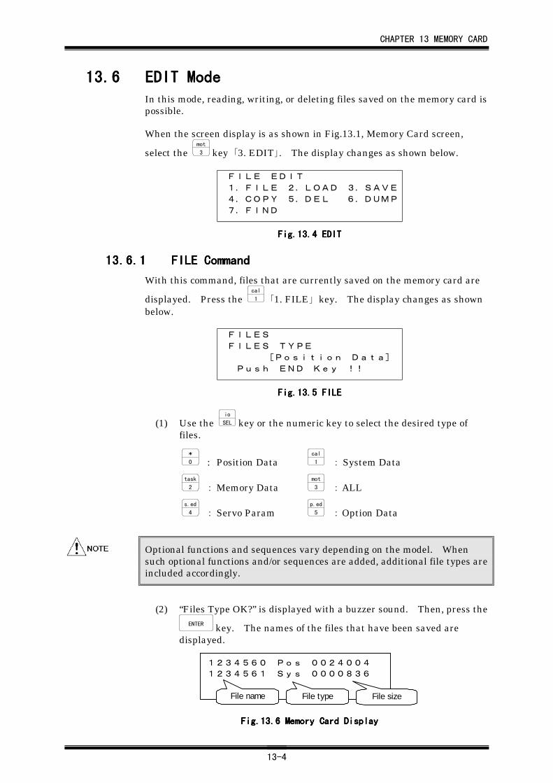
CHAPTER 13 MEMORY CARD
13-4
13.613.613.613.6 EDIT ModeEDIT ModeEDIT ModeEDIT ModeIn this mode, reading, writing, or deleting files saved on the memory card ispossible.
When the screen display is as shown in Fig.13.1, Memory Card screen,
select the mot
3 key 「3. EDIT」. The display changes as shown below.
FILE EDIT
1.FILE 2.LOAD 3.SAVE4.COPY 5.DEL 6.DUMP
7.FIND
Fig.13.Fig.13.Fig.13.Fig.13.4444 EDITEDITEDITEDIT
13.6.113.6.113.6.113.6.1 FILE CommandFILE CommandFILE CommandFILE Command
With this command, files that are currently saved on the memory card are
displayed. Press the cal
1 「1. FILE」 key. The display changes as shownbelow.
FILES
FILES TYPE
[Position Data] Push END Key !!
Fig.13.Fig.13.Fig.13.Fig.13.5555 FILEFILEFILEFILE
(1) Use the io
SEL key or the numeric key to select the desired type offiles.
*
0 : Position Datacal
1 : System Data
task
2 : Memory Datamot
3 : ALL
s.ed
4 : Servo Paramp.ed
5 : Option Data
Optional functions and sequences vary depending on the model. Whensuch optional functions and/or sequences are added, additional file types areincluded accordingly.
(2) “Files Type OK?” is displayed with a buzzer sound. Then, press theENTER key. The names of the files that have been saved are
displayed.
1234560 Pos 0024004
1234561 Sys 0000836
File name File type File size
Fig.13.Fig.13.Fig.13.Fig.13.6666 Memory Card Display Memory Card Display Memory Card Display Memory Card Display
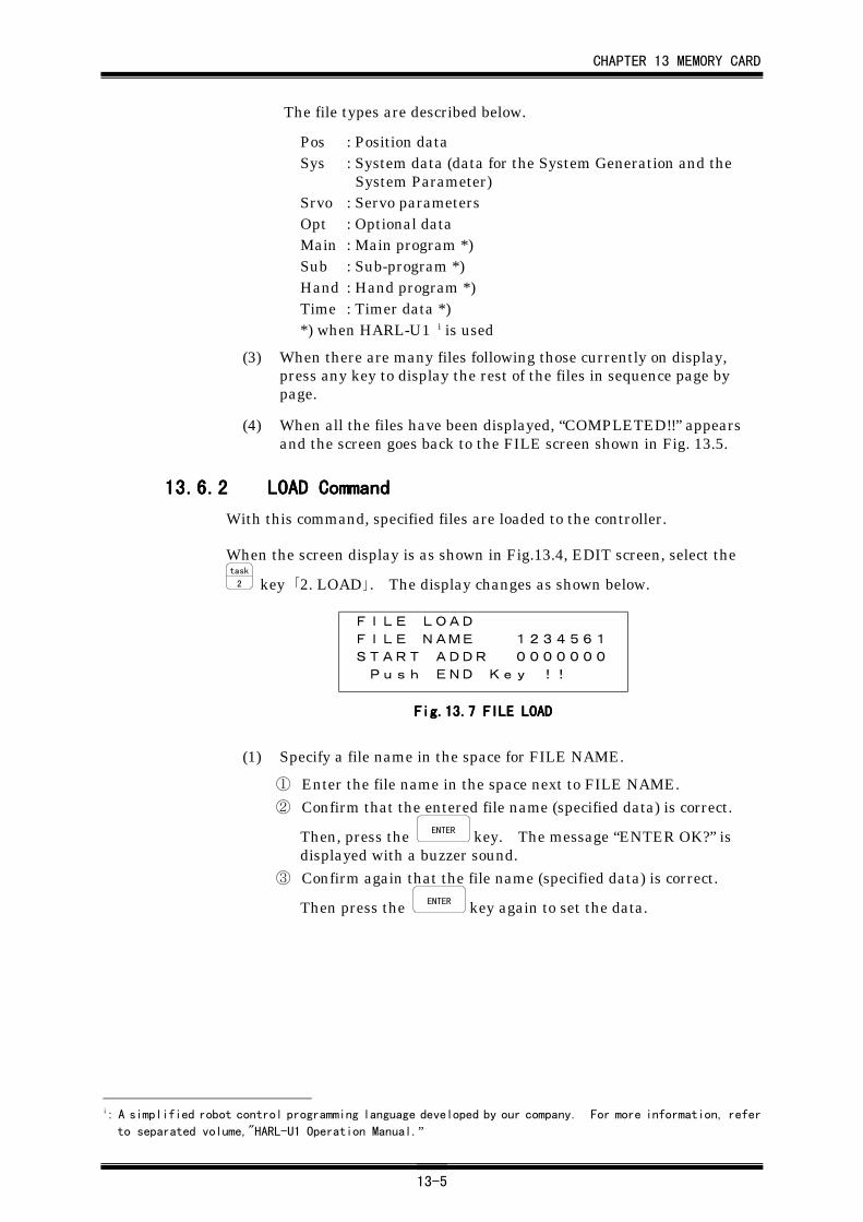
CHAPTER 13 MEMORY CARD
13-5
The file types are described below.
Pos : Position dataSys : System data (data for the System Generation and the
System Parameter)Srvo : Servo parametersOpt : Optional dataMain : Main program *)Sub : Sub-program *)Hand : Hand program *)Time : Timer data *)*) when HARL-U1 i is used
(3) When there are many files following those currently on display,press any key to display the rest of the files in sequence page bypage.
(4) When all the files have been displayed, “COMPLETED!!” appearsand the screen goes back to the FILE screen shown in Fig. 13.5.
13.6.213.6.213.6.213.6.2 LOAD CommandLOAD CommandLOAD CommandLOAD Command
With this command, specified files are loaded to the controller.
When the screen display is as shown in Fig.13.4, EDIT screen, select thetask
2 key 「2. LOAD」. The display changes as shown below.
FILE LOAD
FILE NAME 1234561START ADDR 0000000 Push END Key !!
Fig.13.Fig.13.Fig.13.Fig.13.7777 FILE LOADFILE LOADFILE LOADFILE LOAD
(1) Specify a file name in the space for FILE NAME.
① Enter the file name in the space next to FILE NAME.② Confirm that the entered file name (specified data) is correct.
Then, press the ENTER key. The message “ENTER OK?” isdisplayed with a buzzer sound.
③ Confirm again that the file name (specified data) is correct.
Then press the ENTER key again to set the data.
i: A simplified robot control programming language developed by our company. For more information, refer
to separated volume,"HARL-U1 Operation Manual.”
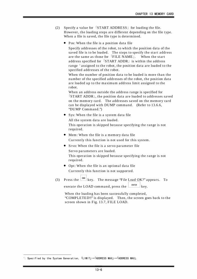
CHAPTER 13 MEMORY CARD
13-6
(2) Specify a value for 「START ADDRESS」 for loading the file.However, the loading steps are different depending on the file type.When a file is saved, the file type is determined.
• Pos: When the file is a position data fileSpecify addresses of the robot, to which the position data of thesaved file is to be loaded. The steps to specify the start addressare the same as those for 「FILE NAME」. When the startaddress specified for 「START ADDR」 is within the addressrange i assigned to the robot, the position data are loaded to thespecified addresses of the robot.When the number of position data to be loaded is more than thenumber of the specified addresses of the robot, the position dataare loaded up to the maximum address limit assigned to therobot.When an address outside the address range is specified for「START ADDR」, the position data are loaded to addresses savedon the memory card. The addresses saved on the memory cardcan be displayed with DUMP command. (Refer to 13.6.6,“DUMP Command.”)
• Sys: When the file is a system data fileAll the system data are loaded.This operation is skipped because specifying the range is notrequired.
• Mem: When the file is a memory data fileCurrently this function is not used for this system.
• Srvo: When the file is a servo parameter fileServo parameters are loaded.This operation is skipped because specifying the range is notrequired.
• Opt: When the file is an optional data fileCurrently this function is not supported.
(3) Press the END key. The message “File Load OK?” appears. To
execute the LOAD command, press the ENTER key.
When the loading has been successfully completed,“COMPLETED!!” is displayed. Then, the screen goes back to thescreen shown in Fig. 13.7, FILE LOAD.
i: Specified by the System Generation, 「LIMIT」→「ADDRESS MAX」→「ADDRESS MAX」.
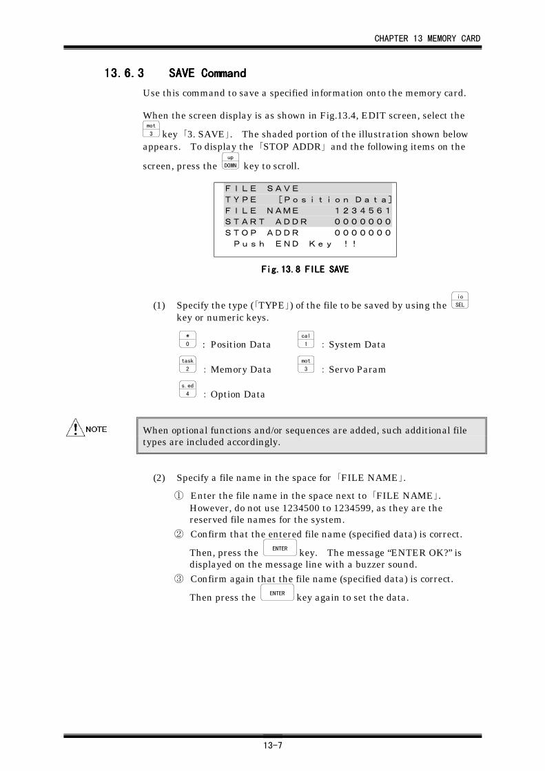
CHAPTER 13 MEMORY CARD
13-7
13.6.313.6.313.6.313.6.3 SAVE CommandSAVE CommandSAVE CommandSAVE Command
Use this command to save a specified information onto the memory card.
When the screen display is as shown in Fig.13.4, EDIT screen, select themot
3 key 「3. SAVE」. The shaded portion of the illustration shown belowappears. To display the 「STOP ADDR」 and the following items on the
screen, press the up
DOWN key to scroll.
FILE SAVE
TYPE [Position Data]FILE NAME 1234561START ADDR 0000000STOP ADDR 0000000 Push END Key !!
FigFigFigFig....13.13.13.13.8888 FILE SAVEFILE SAVEFILE SAVEFILE SAVE
(1) Specify the type (「TYPE」) of the file to be saved by using the io
SEL
key or numeric keys.
*
0 : Position Datacal
1 : System Data
task
2 : Memory Datamot
3 : Servo Param
s.ed
4 : Option Data
When optional functions and/or sequences are added, such additional filetypes are included accordingly.
(2) Specify a file name in the space for 「FILE NAME」.
① Enter the file name in the space next to 「FILE NAME」.However, do not use 1234500 to 1234599, as they are thereserved file names for the system.
② Confirm that the entered file name (specified data) is correct.
Then, press the ENTER key. The message “ENTER OK?” isdisplayed on the message line with a buzzer sound.
③ Confirm again that the file name (specified data) is correct.
Then press the ENTER key again to set the data.
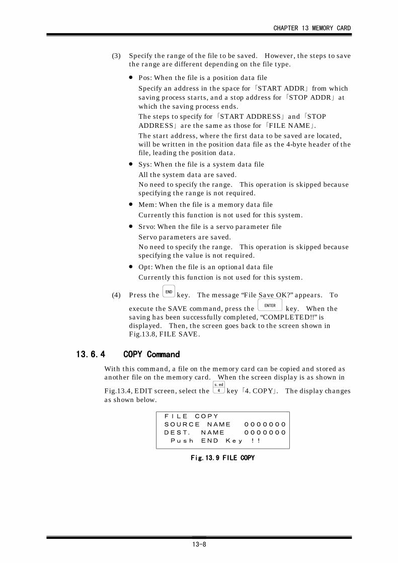
CHAPTER 13 MEMORY CARD
13-8
(3) Specify the range of the file to be saved. However, the steps to savethe range are different depending on the file type.
• Pos: When the file is a position data file
Specify an address in the space for 「START ADDR」 from whichsaving process starts, and a stop address for 「STOP ADDR」 atwhich the saving process ends.The steps to specify for 「START ADDRESS」 and 「STOPADDRESS」 are the same as those for 「FILE NAME」.The start address, where the first data to be saved are located,will be written in the position data file as the 4-byte header of thefile, leading the position data.
• Sys: When the file is a system data fileAll the system data are saved.No need to specify the range. This operation is skipped becausespecifying the range is not required.
• Mem: When the file is a memory data fileCurrently this function is not used for this system.
• Srvo: When the file is a servo parameter fileServo parameters are saved.No need to specify the range. This operation is skipped becausespecifying the value is not required.
• Opt: When the file is an optional data fileCurrently this function is not used for this system.
(4) Press the END key. The message “File Save OK?” appears. To
execute the SAVE command, press the ENTER key. When the
saving has been successfully completed, “COMPLETED!!” isdisplayed. Then, the screen goes back to the screen shown inFig.13.8, FILE SAVE.
13.6.413.6.413.6.413.6.4 COPY CommandCOPY CommandCOPY CommandCOPY Command
With this command, a file on the memory card can be copied and stored asanother file on the memory card. When the screen display is as shown in
Fig.13.4, EDIT screen, select the s.ed
4 key 「4. COPY」. The display changesas shown below.
FILE COPY
SOURCE NAME 0000000DEST. NAME 0000000 Push END Key !!
FigFigFigFig....13.13.13.13.9999 FILE COPYFILE COPYFILE COPYFILE COPY
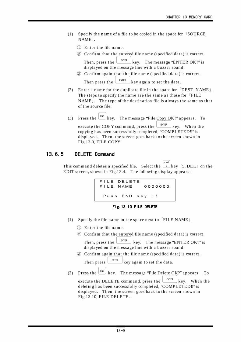
CHAPTER 13 MEMORY CARD
13-9
(1) Specify the name of a file to be copied in the space for 「SOURCENAME」.
① Enter the file name.② Confirm that the entered file name (specified data) is correct.
Then, press the ENTER key. The message “ENTER OK?” isdisplayed on the message line with a buzzer sound.
③ Confirm again that the file name (specified data) is correct.
Then press the ENTER key again to set the data.
(2) Enter a name for the duplicate file in the space for 「DEST. NAME」.The steps to specify the name are the same as those for 「FILENAME」. The type of the destination file is always the same as thatof the source file.
(3) Press the END key. The message “File Copy OK?” appears. To
execute the COPY command, press the ENTER key. When thecopying has been successfully completed, “COMPLETED!!” isdisplayed. Then, the screen goes back to the screen shown inFig.13.9, FILE COPY.
13.6.513.6.513.6.513.6.5 DELETE CommandDELETE CommandDELETE CommandDELETE Command
This command deletes a specified file. Select the p.ed
5 key 「5. DEL」 on theEDIT screen, shown in Fig.13.4. The following display appears:
FILE DELETE
FILE NAME 0000000
Push END Key !!
FigFigFigFig....13.13.13.13.10101010 FILE FILE FILE FILE DELETEDELETEDELETEDELETE
(1) Specify the file name in the space next to 「FILE NAME」.
① Enter the file name.② Confirm that the entered file name (specified data) is correct.
Then, press the ENTER key. The message “ENTER OK?” is
displayed on the message line with a buzzer sound.③ Confirm again that the file name (specified data) is correct.
Then press ENTER key again to set the data.
(2) Press the END key. The message “File Delete OK?” appears. To
execute the DELETE command, press the ENTER key. When thedeleting has been successfully completed, “COMPLETED!!” isdisplayed. Then, the screen goes back to the screen shown inFig.13.10, FILE DELETE.
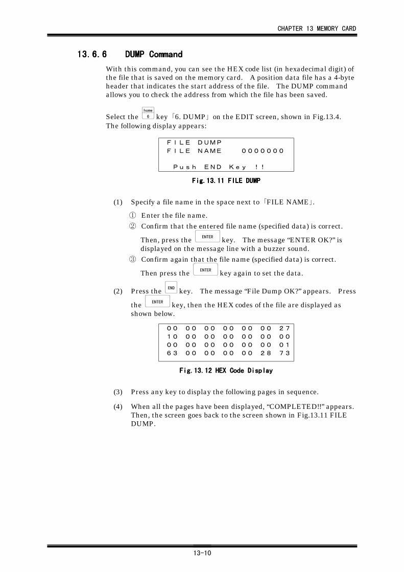
CHAPTER 13 MEMORY CARD
13-10
13.6.613.6.613.6.613.6.6 DUMP CommandDUMP CommandDUMP CommandDUMP Command
With this command, you can see the HEX code list (in hexadecimal digit) ofthe file that is saved on the memory card. A position data file has a 4-byteheader that indicates the start address of the file. The DUMP commandallows you to check the address from which the file has been saved.
Select the home
6 key 「6. DUMP」 on the EDIT screen, shown in Fig.13.4.The following display appears:
FILE DUMP
FILE NAME 0000000
Push END Key !!
FigFigFigFig....13.13.13.13.11111111 FILE FILE FILE FILE DUMPDUMPDUMPDUMP
(1) Specify a file name in the space next to 「FILE NAME」.
① Enter the file name.② Confirm that the entered file name (specified data) is correct.
Then, press the ENTER key. The message “ENTER OK?” isdisplayed on the message line with a buzzer sound.
③ Confirm again that the file name (specified data) is correct.
Then press the ENTER key again to set the data.
(2) Press the END key. The message “File Dump OK?” appears. Press
the ENTER key, then the HEX codes of the file are displayed asshown below.
00 00 00 00 00 00 2710 00 00 00 00 00 0000 00 00 00 00 00 0163 00 00 00 00 28 73
Fig.13.Fig.13.Fig.13.Fig.13.12121212 HEX Code Display HEX Code Display HEX Code Display HEX Code Display
(3) Press any key to display the following pages in sequence.
(4) When all the pages have been displayed, “COMPLETED!!” appears.Then, the screen goes back to the screen shown in Fig.13.11 FILEDUMP.
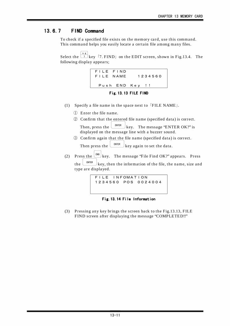
CHAPTER 13 MEMORY CARD
13-11
13.6.713.6.713.6.713.6.7 FIND CommandFIND CommandFIND CommandFIND Command
To check if a specified file exists on the memory card, use this command.This command helps you easily locate a certain file among many files.
Select the s.g
7 key 「7. FIND」 on the EDIT screen, shown in Fig.13.4. Thefollowing display appears;
FILE FIND
FILE NAME 1234560
Push END Key !!
Fig.13.Fig.13.Fig.13.Fig.13.13131313 FILE FIND FILE FIND FILE FIND FILE FIND
(1) Specify a file name in the space next to 「FILE NAME」.
① Enter the file name.② Confirm that the entered file name (specified data) is correct.
Then, press the ENTER key. The message “ENTER OK?” isdisplayed on the message line with a buzzer sound.
③ Confirm again that the file name (specified data) is correct.
Then press the ENTER key again to set the data.
(2) Press the END key. The message “File Find OK?” appears. Press
the ENTER key, then the information of the file, the name, size andtype are displayed.
FILE INFOMATION
1234560 POS 0024004
Fig.13.Fig.13.Fig.13.Fig.13.14141414 File Information File Information File Information File Information
(3) Pressing any key brings the screen back to the Fig.13.13, FILEFIND screen after displaying the message “COMPLETED!!”
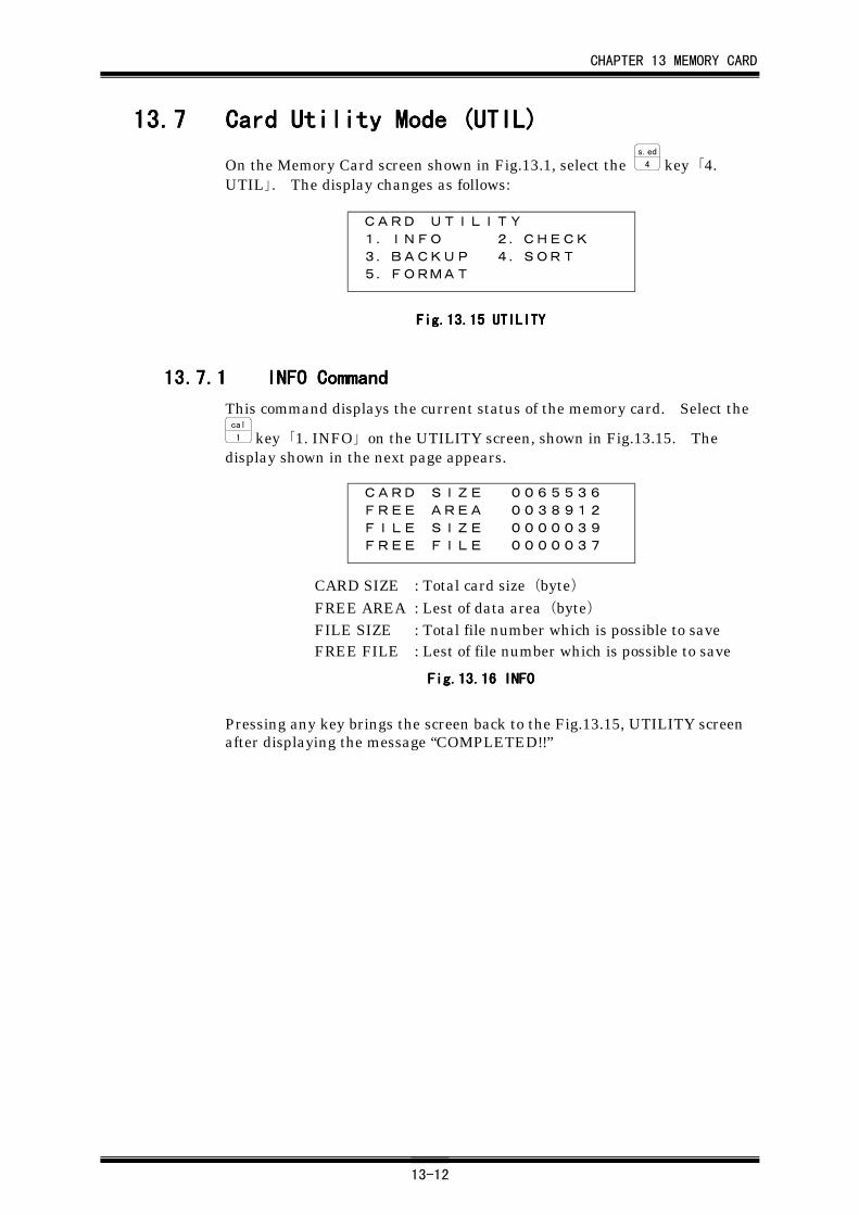
CHAPTER 13 MEMORY CARD
13-12
13.713.713.713.7 Card Utility Mode (UTIL)Card Utility Mode (UTIL)Card Utility Mode (UTIL)Card Utility Mode (UTIL)
On the Memory Card screen shown in Fig.13.1, select the s.ed
4 key 「4.UTIL」. The display changes as follows:
CARD UTILITY
1.INFO 2.CHECK
3.BACKUP 4.SORT
5.FORMAT
Fig.13.Fig.13.Fig.13.Fig.13.15151515 UTILITY UTILITY UTILITY UTILITY
13.7.113.7.113.7.113.7.1 INFO CommandINFO CommandINFO CommandINFO Command
This command displays the current status of the memory card. Select thecal
1 key 「1. INFO」 on the UTILITY screen, shown in Fig.13.15. Thedisplay shown in the next page appears.
CARD SIZE 0065536FREE AREA 0038912FILE SIZE 0000039FREE FILE 0000037
CARD SIZE : Total card size(byte)FREE AREA : Lest of data area(byte)FILE SIZE : Total file number which is possible to saveFREE FILE : Lest of file number which is possible to save
Fig.13.Fig.13.Fig.13.Fig.13.16161616 INFO INFO INFO INFO
Pressing any key brings the screen back to the Fig.13.15, UTILITY screenafter displaying the message “COMPLETED!!”
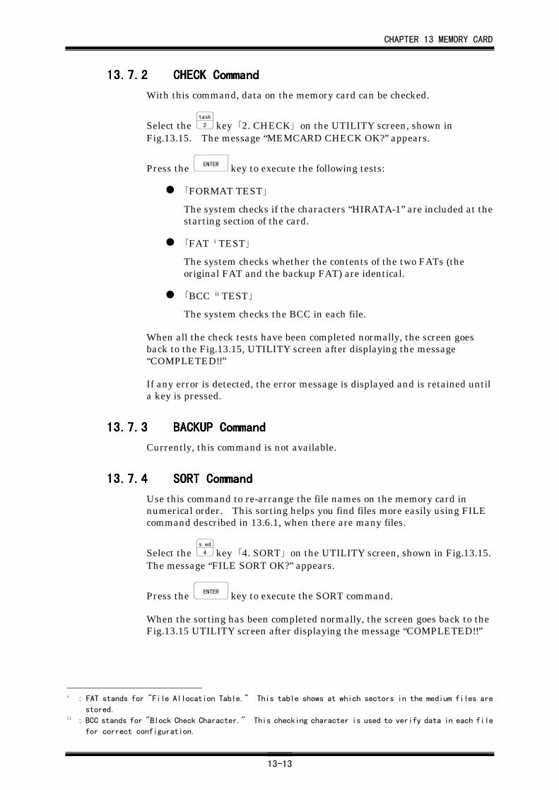
CHAPTER 13 MEMORY CARD
13-13
13.7.213.7.213.7.213.7.2 CHECK CommandCHECK CommandCHECK CommandCHECK Command
With this command, data on the memory card can be checked.
Select the task
2 key 「2. CHECK」 on the UTILITY screen, shown inFig.13.15. The message “MEMCARD CHECK OK?” appears.
Press the ENTER key to execute the following tests:
「FORMAT TEST」
The system checks if the characters “HIRATA-1” are included at thestarting section of the card.
「FAT i TEST」
The system checks whether the contents of the two FATs (theoriginal FAT and the backup FAT) are identical.
「BCC ii TEST」
The system checks the BCC in each file.
When all the check tests have been completed normally, the screen goesback to the Fig.13.15, UTILITY screen after displaying the message“COMPLETED!!”
If any error is detected, the error message is displayed and is retained untila key is pressed.
13.7.313.7.313.7.313.7.3 BACKUP CommandBACKUP CommandBACKUP CommandBACKUP Command
Currently, this command is not available.
13.7.413.7.413.7.413.7.4 SORT CommandSORT CommandSORT CommandSORT Command
Use this command to re-arrange the file names on the memory card innumerical order. This sorting helps you find files more easily using FILEcommand described in 13.6.1, when there are many files.
Select the s.ed
4 key 「4. SORT」 on the UTILITY screen, shown in Fig.13.15.The message “FILE SORT OK?” appears.
Press the ENTER key to execute the SORT command.
When the sorting has been completed normally, the screen goes back to theFig.13.15 UTILITY screen after displaying the message “COMPLETED!!”
i : FAT stands for "File Allocation Table." This table shows at which sectors in the medium files are
stored.ii : BCC stands for "Block Check Character." This checking character is used to verify data in each file
for correct configuration.
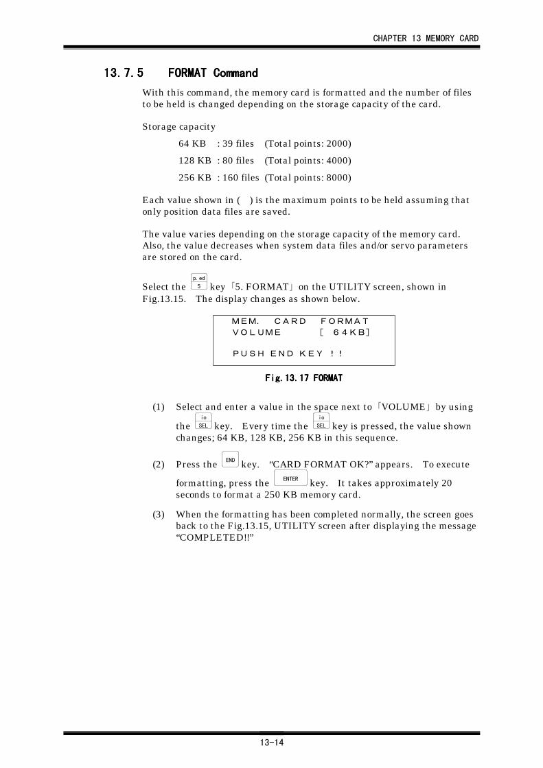
CHAPTER 13 MEMORY CARD
13-14
13.7.513.7.513.7.513.7.5 FORMAT CommandFORMAT CommandFORMAT CommandFORMAT Command
With this command, the memory card is formatted and the number of filesto be held is changed depending on the storage capacity of the card.
Storage capacity
64 KB : 39 files (Total points: 2000)
128 KB : 80 files (Total points: 4000)
256 KB : 160 files (Total points: 8000)
Each value shown in ( ) is the maximum points to be held assuming thatonly position data files are saved.
The value varies depending on the storage capacity of the memory card.Also, the value decreases when system data files and/or servo parametersare stored on the card.
Select the p.ed
5 key 「5. FORMAT」 on the UTILITY screen, shown inFig.13.15. The display changes as shown below.
MEM. CARD FORMAT VOLUME [ 64KB]
PUSH END KEY !!
Fig.13.Fig.13.Fig.13.Fig.13.17171717 FORMAT FORMAT FORMAT FORMAT
(1) Select and enter a value in the space next to 「VOLUME」 by using
the io
SEL key. Every time the io
SEL key is pressed, the value shownchanges; 64 KB, 128 KB, 256 KB in this sequence.
(2) Press the END key. “CARD FORMAT OK?” appears. To execute
formatting, press the ENTER key. It takes approximately 20seconds to format a 250 KB memory card.
(3) When the formatting has been completed normally, the screen goesback to the Fig.13.15, UTILITY screen after displaying the message“COMPLETED!!”
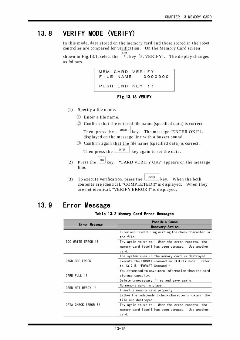
CHAPTER 13 MEMORY CARD
13-15
13.813.813.813.8 VERIFY MODE (VERIFY)VERIFY MODE (VERIFY)VERIFY MODE (VERIFY)VERIFY MODE (VERIFY)In this mode, data stored on the memory card and those stored in the robotcontroller are compared for verification. On the Memory Card screen
shown in Fig.13.1, select the p.ed
5 key 「5. VERIFY」. The display changesas follows.
MEM.CARD VERIFY
FILE NAME 0000000
PUSH END KEY !!
Fig.13.Fig.13.Fig.13.Fig.13.18181818 VERIFY VERIFY VERIFY VERIFY
(1) Specify a file name.
① Enter a file name.
② Confirm that the entered file name (specified data) is correct.
Then, press the ENTER key. The message “ENTER OK?” isdisplayed on the message line with a buzzer sound.
③ Confirm again that the file name (specified data) is correct.
Then press the ENTER key again to set the data.
(2) Press the END key. “CARD VERIFY OK?” appears on the messageline.
(3) To execute verification, press the ENTER key. When the bothcontents are identical, “COMPLETED!!” is displayed. When theyare not identical, “VERIFY ERROR!!” is displayed.
13.913.913.913.9 Error MessageError MessageError MessageError MessageTableTableTableTable 13.13.13.13.2222 Memory Card Error Messages Memory Card Error Messages Memory Card Error Messages Memory Card Error Messages
Possible CausePossible CausePossible CausePossible CauseError MessageError MessageError MessageError Message
Recovery ActionRecovery ActionRecovery ActionRecovery Action
Error occurred during writing the check character in
the file.
BCC WRITE ERROR !! Try again to write. When the error repeats, the
memory card itself has been damaged. Use another
card.
The system area in the memory card is destroyed.
CARD BCC ERROR Execute the FORMAT command in UTILITY mode. Refer
to 13.7.5, “FORMAT Command.”You attempted to save more information than the card
storage capacity.CARD FULL !!
Delete unnecessary files and save again.
No memory card in place.CARD NOT READY !!
Insert a memory card properly.
Either the independent check character or data in the
file are destroyed.
DATA CHECK ERROR !! Try again to write. When the error repeats, the
memory card itself has been damaged. Use another
card.
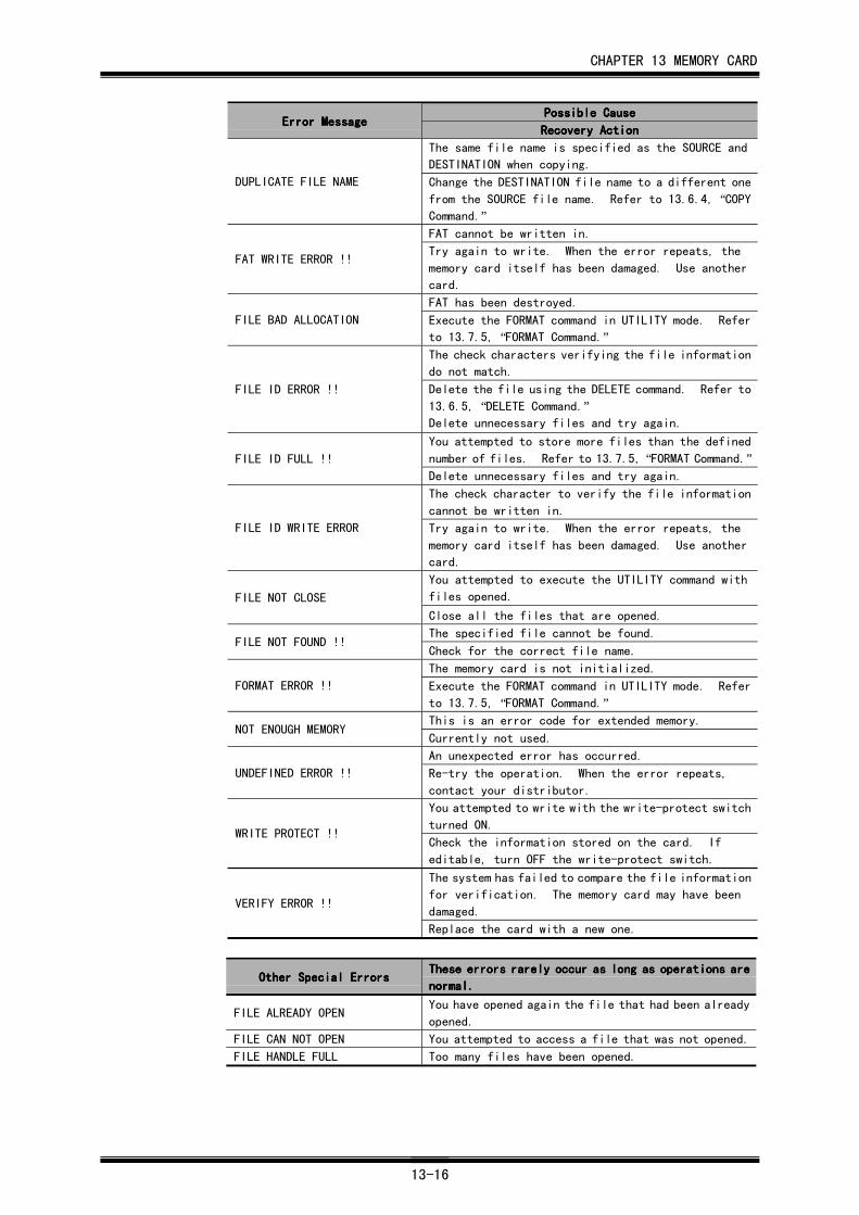
CHAPTER 13 MEMORY CARD
13-16
Possible CausePossible CausePossible CausePossible CauseError MessageError MessageError MessageError Message
Recovery ActionRecovery ActionRecovery ActionRecovery Action
The same file name is specified as the SOURCE and
DESTINATION when copying.
DUPLICATE FILE NAME Change the DESTINATION file name to a different one
from the SOURCE file name. Refer to 13.6.4, “COPYCommand.”FAT cannot be written in.
FAT WRITE ERROR !!Try again to write. When the error repeats, the
memory card itself has been damaged. Use another
card.
FAT has been destroyed.
FILE BAD ALLOCATION Execute the FORMAT command in UTILITY mode. Refer
to 13.7.5, “FORMAT Command.”The check characters verifying the file information
do not match.
FILE ID ERROR !! Delete the file using the DELETE command. Refer to
13.6.5, “DELETE Command.”Delete unnecessary files and try again.
You attempted to store more files than the defined
number of files. Refer to 13.7.5, “FORMAT Command.”FILE ID FULL !!
Delete unnecessary files and try again.
The check character to verify the file information
cannot be written in.
FILE ID WRITE ERROR Try again to write. When the error repeats, the
memory card itself has been damaged. Use another
card.
You attempted to execute the UTILITY command with
files opened.FILE NOT CLOSE
Close all the files that are opened.
The specified file cannot be found.FILE NOT FOUND !!
Check for the correct file name.
The memory card is not initialized.
FORMAT ERROR !! Execute the FORMAT command in UTILITY mode. Refer
to 13.7.5, “FORMAT Command.”This is an error code for extended memory.
NOT ENOUGH MEMORYCurrently not used.
An unexpected error has occurred.
UNDEFINED ERROR !! Re-try the operation. When the error repeats,
contact your distributor.
You attempted to write with the write-protect switch
turned ON.WRITE PROTECT !!
Check the information stored on the card. If
editable, turn OFF the write-protect switch.
The system has failed to compare the file information
for verification. The memory card may have been
damaged.VERIFY ERROR !!
Replace the card with a new one.
Other Special ErrorsOther Special ErrorsOther Special ErrorsOther Special ErrorsThese errors rarely occur as long as operations areThese errors rarely occur as long as operations areThese errors rarely occur as long as operations areThese errors rarely occur as long as operations are
normal.normal.normal.normal.
FILE ALREADY OPENYou have opened again the file that had been already
opened.
FILE CAN NOT OPEN You attempted to access a file that was not opened.
FILE HANDLE FULL Too many files have been opened.
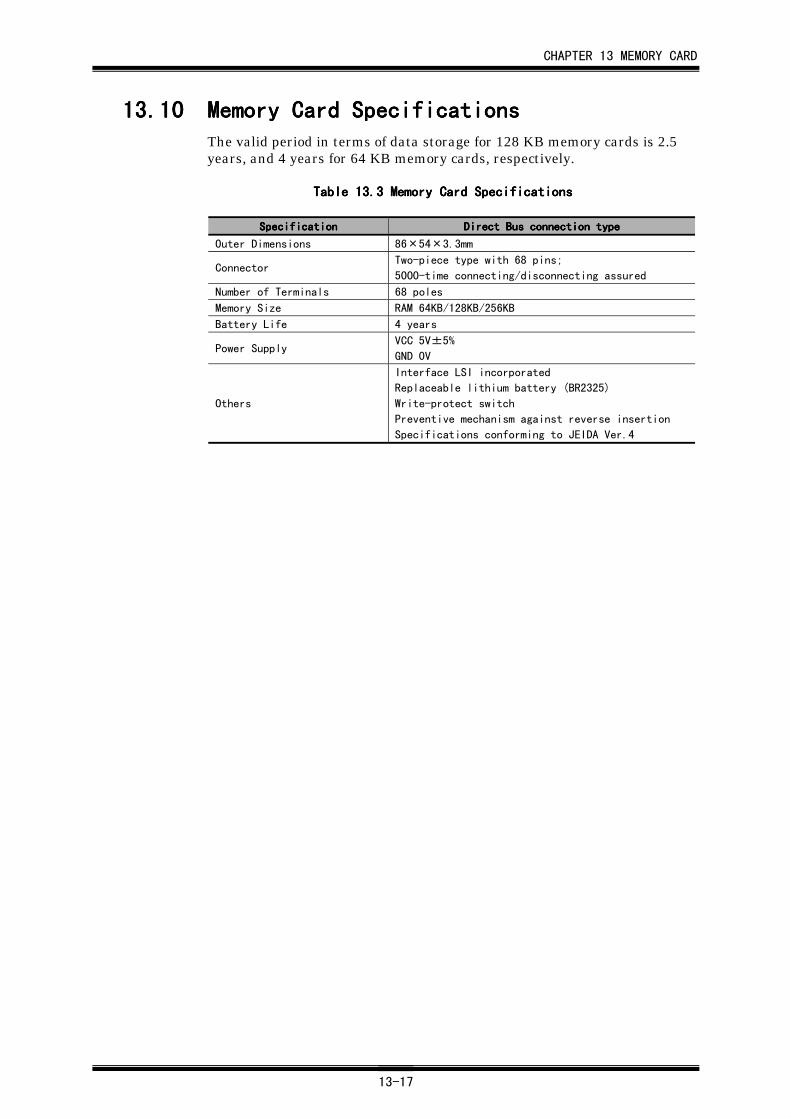
CHAPTER 13 MEMORY CARD
13-17
13.1013.1013.1013.10 Memory Card SpecificationsMemory Card SpecificationsMemory Card SpecificationsMemory Card SpecificationsThe valid period in terms of data storage for 128 KB memory cards is 2.5years, and 4 years for 64 KB memory cards, respectively.
Table 13.Table 13.Table 13.Table 13.3333 Memory Card Specifications Memory Card Specifications Memory Card Specifications Memory Card Specifications
SpecificationSpecificationSpecificationSpecification Direct Bus connection typeDirect Bus connection typeDirect Bus connection typeDirect Bus connection type
Outer Dimensions 86×54×3.3mm
ConnectorTwo-piece type with 68 pins;
5000-time connecting/disconnecting assured
Number of Terminals 68 poles
Memory Size RAM 64KB/128KB/256KB
Battery Life 4 years
Power SupplyVCC 5V±5%
GND 0V
Others
Interface LSI incorporated
Replaceable lithium battery (BR2325)
Write-protect switch
Preventive mechanism against reverse insertion
Specifications conforming to JEIDA Ver.4
CHAPTER 14 W-AXIS SENSOR STOP
14-1
CHAPTER 14CHAPTER 14CHAPTER 14CHAPTER 14 W-Axis Sensor StopW-Axis Sensor StopW-Axis Sensor StopW-Axis Sensor Stop
This is the positioning function to stop W-Axis when the input signal isturned ON.
Currently this function is not used for this system.
CHAPTER 15 OPERATION METHOD FOR VISION IN AUTO MODE
15-1
CHAPTER 15CHAPTER 15CHAPTER 15CHAPTER 15 Operation Method for Vision inOperation Method for Vision inOperation Method for Vision inOperation Method for Vision in
AUTO ModeAUTO ModeAUTO ModeAUTO Mode
Currently this function is not used for this system.
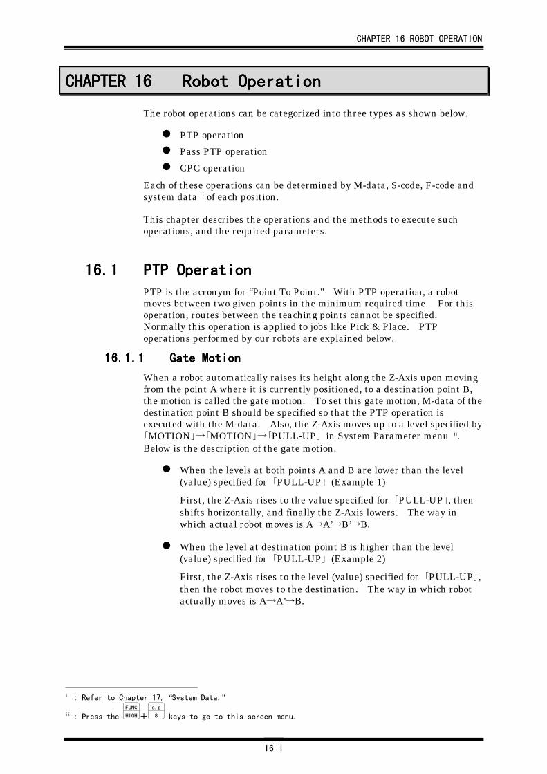
CHAPTER 16 ROBOT OPERATION
16-1
CHAPTER 16CHAPTER 16CHAPTER 16CHAPTER 16 Robot OperationRobot OperationRobot OperationRobot Operation
The robot operations can be categorized into three types as shown below.
PTP operation
Pass PTP operation
CPC operation
Each of these operations can be determined by M-data, S-code, F-code andsystem data i of each position.
This chapter describes the operations and the methods to execute suchoperations, and the required parameters.
16.116.116.116.1 PTP OperationPTP OperationPTP OperationPTP OperationPTP is the acronym for “Point To Point.” With PTP operation, a robotmoves between two given points in the minimum required time. For thisoperation, routes between the teaching points cannot be specified.Normally this operation is applied to jobs like Pick & Place. PTPoperations performed by our robots are explained below.
16.1.116.1.116.1.116.1.1 Gate MotionGate MotionGate MotionGate Motion
When a robot automatically raises its height along the Z-Axis upon movingfrom the point A where it is currently positioned, to a destination point B,the motion is called the gate motion. To set this gate motion, M-data of thedestination point B should be specified so that the PTP operation isexecuted with the M-data. Also, the Z-Axis moves up to a level specified by「MOTION」→「MOTION」→「PULL-UP」 in System Parameter menu ii.Below is the description of the gate motion.
When the levels at both points A and B are lower than the level(value) specified for 「PULL-UP」 (Example 1)
First, the Z-Axis rises to the value specified for 「PULL-UP」, thenshifts horizontally, and finally the Z-Axis lowers. The way inwhich actual robot moves is A→A’→B’→B.
When the level at destination point B is higher than the level(value) specified for 「PULL-UP」 (Example 2)
First, the Z-Axis rises to the level (value) specified for 「PULL-UP」,then the robot moves to the destination. The way in which robotactually moves is A→A’→B.
i : Refer to Chapter 17, “System Data.”
ii : Press the FUNC
HIGH+s.p
8 keys to go to this screen menu.
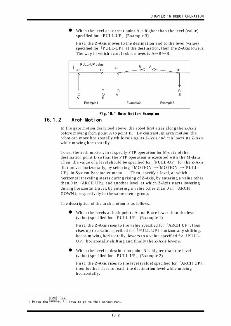
CHAPTER 16 ROBOT OPERATION
16-2
When the level at current point A is higher than the level (value)specified for 「PULL-UP」 (Example 3)
First, the Z-Axis moves to the destination and to the level (value)specified for 「PULL-UP」 at the destination, then the Z-Axis lowers.The way in which actual robot moves is A→B’→B.
A B
A’ B’
A
BA’ A
B
B’PULL-UP value
Example1 Example2 Example3
Fig.16.Fig.16.Fig.16.Fig.16.1111 Gate Motion Examples Gate Motion Examples Gate Motion Examples Gate Motion Examples
16.1.216.1.216.1.216.1.2 Arch MotionArch MotionArch MotionArch Motion
In the gate motion described above, the robot first rises along the Z-Axisbefore moving from point A to point B. By contrast, in arch motion, therobot can move horizontally while raising its Z-Axis and can lower its Z-Axiswhile moving horizontally.
To set the arch motion, first specify PTP operation for M-data of thedestination point B so that the PTP operation is executed with the M-data.Then, the value of a level should be specified for 「PULL-UP」 for the Z-Axisthat moves horizontally, by selecting 「MOTION」→「MOTION」→「PULL-UP」 in System Parameter menu i. Then, specify a level, at whichhorizontal traveling starts during rising of Z-Axis, by entering a value otherthan 0 in 「ARCH UP」, and another level, at which Z-Axis starts loweringduring horizontal travel, by entering a value other than 0 in 「ARCHDOWN」, respectively in the same menu group.
The description of the arch motion is as follows.
When the levels at both points A and B are lower than the level(value) specified for 「PULL-UP」 (Example 1)
First, the Z-Axis rises to the value specified for 「ARCH UP」, thenrises up to a value specified for 「PULL-UP」 horizontally shifting,keeps moving horizontally, lowers to a value specified for 「PULL-UP」 horizontally shifting and finally the Z-Axis lowers.
When the level of destination point B is higher than the level(value) specified for 「PULL-UP」 (Example 2)
First, the Z-Axis rises to the level (value) specified for 「ARCH UP」,then further rises to reach the destination level while movinghorizontally.
i: Press the FUNC
HIGH+s.p
8 keys to go to this screen menu.
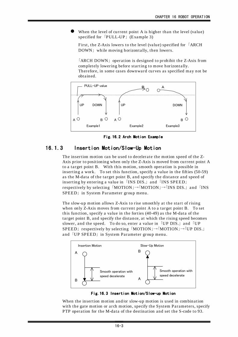
CHAPTER 16 ROBOT OPERATION
16-3
When the level of current point A is higher than the level (value)specified for 「PULL-UP」 (Example 3)
First, the Z-Axis lowers to the level (value) specified for 「ARCHDOWN」 while moving horizontally, then lowers.
「ARCH DOWN」 operation is designed to prohibit the Z-Axis fromcompletely lowering before starting to move horizontally.Therefore, in some cases downward curves as specified may not beobtained.
A B
UP DOWN
A
B
UP
A
B
DOWN
PULL-UP value
Example1 Example2 Example3
Fig.16.Fig.16.Fig.16.Fig.16.2222 Arch Motion Example Arch Motion Example Arch Motion Example Arch Motion Example
16.1.316.1.316.1.316.1.3 Insertion Motion/Slow-Up MotionInsertion Motion/Slow-Up MotionInsertion Motion/Slow-Up MotionInsertion Motion/Slow-Up Motion
The insertion motion can be used to decelerate the motion speed of the Z-Axis prior to positioning when only the Z-Axis is moved from current point Ato a target point B. With this motion, smooth operation is possible ininserting a work. To set this function, specify a value in the fifties (50-59)as the M-data of the target point B, and specify the distance and speed ofinserting by entering a value in 「INS DIS.」 and 「INS SPEED」respectively by selecting 「MOTION」→「MOTION」→「INS DIS.」 and 「INSSPEED」 in System Parameter group menu.
The slow-up motion allows Z-Axis to rise smoothly at the start of risingwhen only Z-Axis moves from current point A to a target point B. To setthis function, specify a value in the forties (40-49) as the M-data of thetarget point B, and specify the distance, at which the rising speed becomesslower, and the speed. To do so, enter a value in 「UP DIS.」 and 「UPSPEED」 respectively by selecting 「MOTION」→「MOTION」→「UP DIS.」and 「UP SPEED」 in System Parameter group menu.
A
B
Smooth operation with
speed decelerate
B
A
Smooth operation with
speed decelerate
Insertion Motion Slow-Up Motion
Fig.16.Fig.16.Fig.16.Fig.16.3333 Insertion Motion/Slow-up Motion Insertion Motion/Slow-up Motion Insertion Motion/Slow-up Motion Insertion Motion/Slow-up Motion
When the insertion motion and/or slow-up motion is used in combinationwith the gate motion or arch motion, specify the System Parameters, specifyPTP operation for the M-data of the destination and set the S-code to 93.
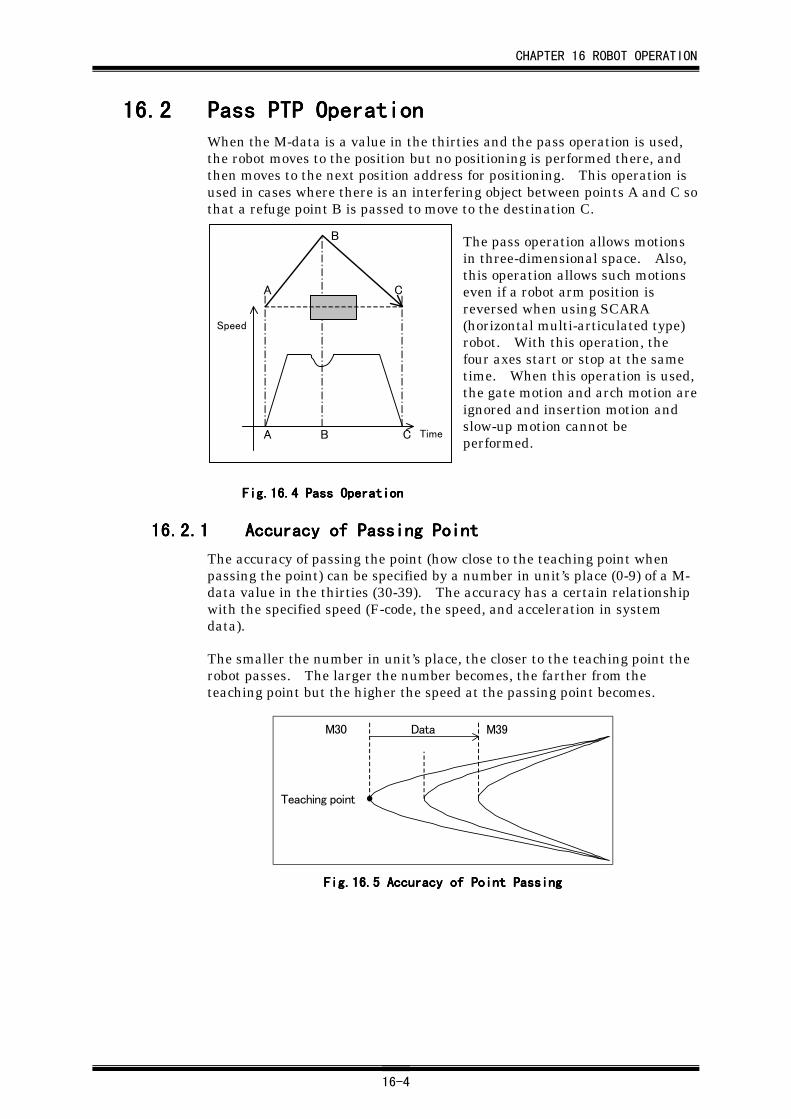
CHAPTER 16 ROBOT OPERATION
16-4
16.216.216.216.2 Pass PTP OperationPass PTP OperationPass PTP OperationPass PTP OperationWhen the M-data is a value in the thirties and the pass operation is used,the robot moves to the position but no positioning is performed there, andthen moves to the next position address for positioning. This operation isused in cases where there is an interfering object between points A and C sothat a refuge point B is passed to move to the destination C.
The pass operation allows motionsin three-dimensional space. Also,this operation allows such motionseven if a robot arm position isreversed when using SCARA(horizontal multi-articulated type)robot. With this operation, thefour axes start or stop at the sametime. When this operation is used,the gate motion and arch motion areignored and insertion motion andslow-up motion cannot beperformed.
Fig.16.Fig.16.Fig.16.Fig.16.4444 Pass Operation Pass Operation Pass Operation Pass Operation
16.2.116.2.116.2.116.2.1 Accuracy of Passing PointAccuracy of Passing PointAccuracy of Passing PointAccuracy of Passing Point
The accuracy of passing the point (how close to the teaching point whenpassing the point) can be specified by a number in unit’s place (0-9) of a M-data value in the thirties (30-39). The accuracy has a certain relationshipwith the specified speed (F-code, the speed, and acceleration in systemdata).
The smaller the number in unit’s place, the closer to the teaching point therobot passes. The larger the number becomes, the farther from theteaching point but the higher the speed at the passing point becomes.
Data M39
Teaching point
M30
Fig.16.Fig.16.Fig.16.Fig.16.5555 Accuracy of Point Passing Accuracy of Point Passing Accuracy of Point Passing Accuracy of Point Passing
A
B
C
A B C
Speed
Time
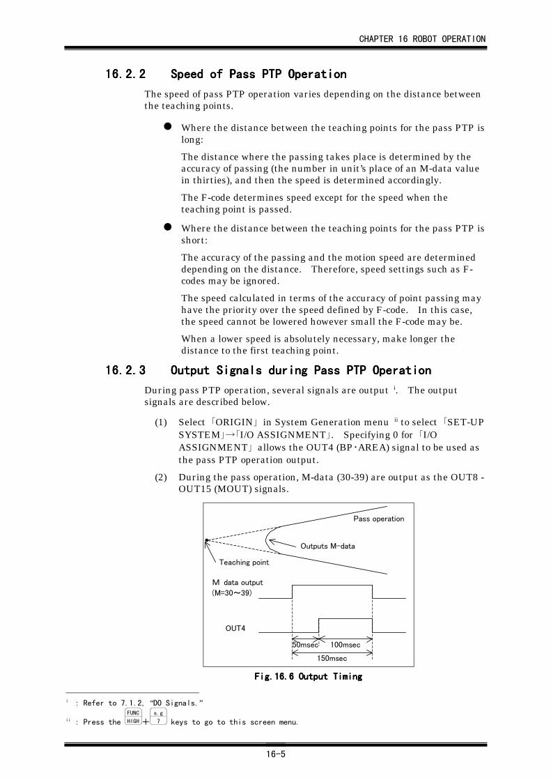
CHAPTER 16 ROBOT OPERATION
16-5
16.2.216.2.216.2.216.2.2 Speed of Pass PTP OperationSpeed of Pass PTP OperationSpeed of Pass PTP OperationSpeed of Pass PTP Operation
The speed of pass PTP operation varies depending on the distance betweenthe teaching points.
Where the distance between the teaching points for the pass PTP islong:
The distance where the passing takes place is determined by theaccuracy of passing (the number in unit’s place of an M-data valuein thirties), and then the speed is determined accordingly.
The F-code determines speed except for the speed when theteaching point is passed.
Where the distance between the teaching points for the pass PTP isshort:
The accuracy of the passing and the motion speed are determineddepending on the distance. Therefore, speed settings such as F-codes may be ignored.
The speed calculated in terms of the accuracy of point passing mayhave the priority over the speed defined by F-code. In this case,the speed cannot be lowered however small the F-code may be.
When a lower speed is absolutely necessary, make longer thedistance to the first teaching point.
16.2.316.2.316.2.316.2.3 Output Signals during Pass PTP OperationOutput Signals during Pass PTP OperationOutput Signals during Pass PTP OperationOutput Signals during Pass PTP Operation
During pass PTP operation, several signals are output i. The outputsignals are described below.
(1) Select 「ORIGIN」 in System Generation menu ii to select 「SET-UPSYSTEM」→「I/O ASSIGNMENT」. Specifying 0 for 「I/OASSIGNMENT」 allows the OUT4 (BP・AREA) signal to be used asthe pass PTP operation output.
(2) During the pass operation, M-data (30-39) are output as the OUT8 -OUT15 (MOUT) signals.
Teaching point
Outputs M-data
Pass operation
50msec 100msec
150msec
M data output
(M=30~39)
OUT4
Fig.16.Fig.16.Fig.16.Fig.16.6666 Output Timing Output Timing Output Timing Output Timing
i : Refer to 7.1.2, “DO Signals.”
ii : Press the FUNC
HIGH+s.g
7 keys to go to this screen menu.
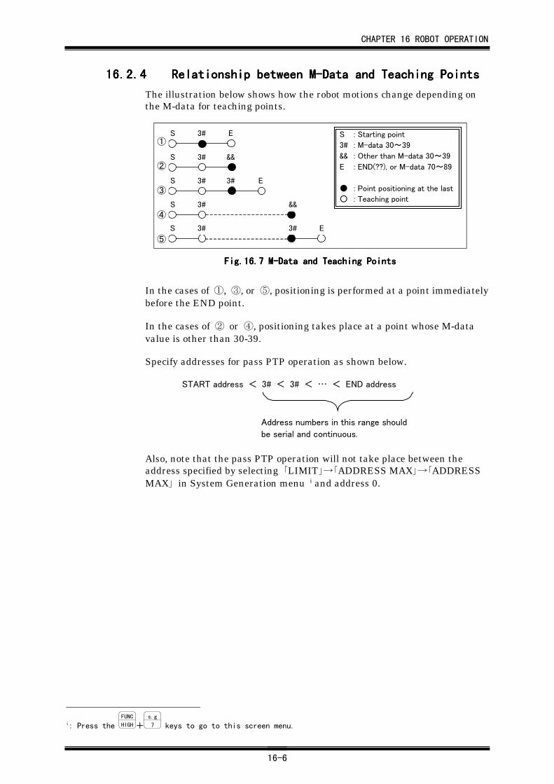
CHAPTER 16 ROBOT OPERATION
16-6
16.2.416.2.416.2.416.2.4 Relationship between M-Data and Teaching PointsRelationship between M-Data and Teaching PointsRelationship between M-Data and Teaching PointsRelationship between M-Data and Teaching Points
The illustration below shows how the robot motions change depending onthe M-data for teaching points.
S 3# E
S 3# &&
S 3# 3# E
S 3# 3# E
S 3# &&
S : Starting point
3# : M-data 30~39
&& : Other than M-data 30~39
E : END(??), or M-data 70~89
● : Point positioning at the last
○ : Teaching point
①
②
③
④
⑤
Fig.16.Fig.16.Fig.16.Fig.16.7777 M-Data and Teaching Points M-Data and Teaching Points M-Data and Teaching Points M-Data and Teaching Points
In the cases of ①, ③, or ⑤, positioning is performed at a point immediatelybefore the END point.
In the cases of ② or ④, positioning takes place at a point whose M-datavalue is other than 30-39.
Specify addresses for pass PTP operation as shown below.
Address numbers in this range should
be serial and continuous.
START address < 3# < 3# < … < END address
Also, note that the pass PTP operation will not take place between theaddress specified by selecting 「LIMIT」→「ADDRESS MAX」→「ADDRESSMAX」 in System Generation menu i and address 0.
i: Press the FUNC
HIGH+s.g
7 keys to go to this screen menu.
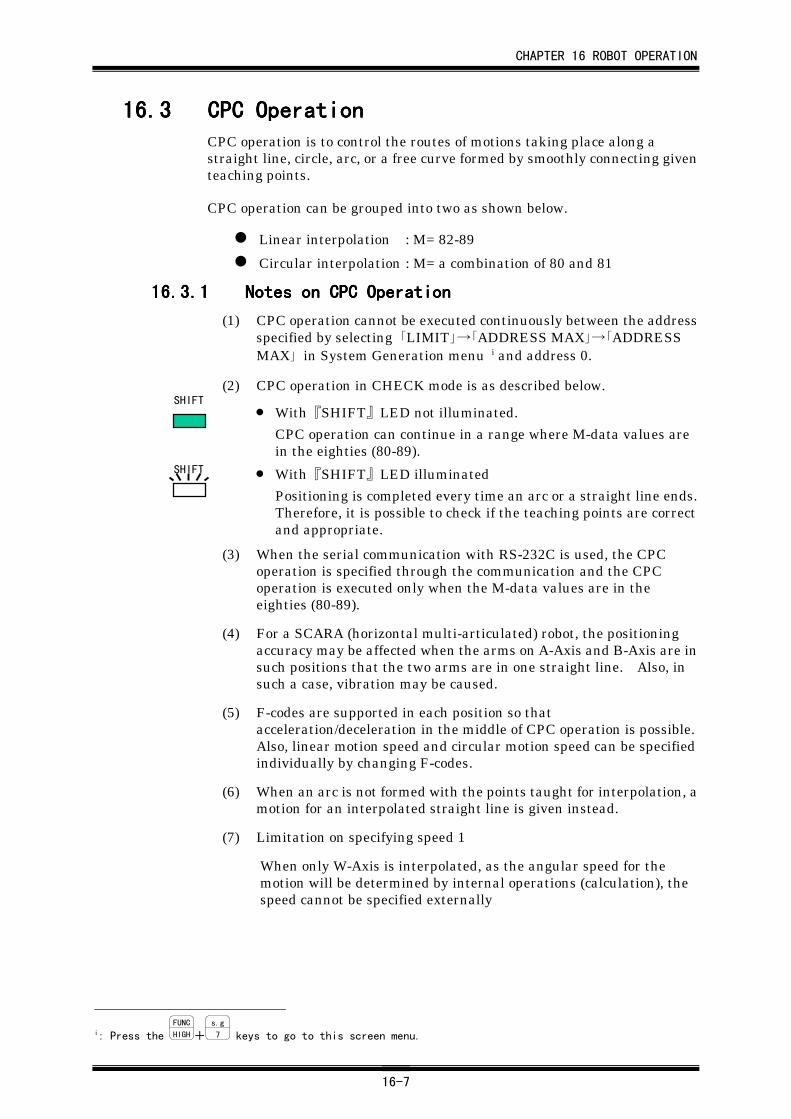
CHAPTER 16 ROBOT OPERATION
16-7
16.316.316.316.3 CPC OperationCPC OperationCPC OperationCPC OperationCPC operation is to control the routes of motions taking place along astraight line, circle, arc, or a free curve formed by smoothly connecting giventeaching points.
CPC operation can be grouped into two as shown below.
Linear interpolation : M= 82-89
Circular interpolation : M= a combination of 80 and 81
16.3.116.3.116.3.116.3.1 Notes on CPC OperationNotes on CPC OperationNotes on CPC OperationNotes on CPC Operation
(1) CPC operation cannot be executed continuously between the addressspecified by selecting 「LIMIT」→「ADDRESS MAX」→「ADDRESSMAX」 in System Generation menu i and address 0.
(2) CPC operation in CHECK mode is as described below.
• With『SHIFT』LED not illuminated.
CPC operation can continue in a range where M-data values arein the eighties (80-89).
• With『SHIFT』LED illuminated
Positioning is completed every time an arc or a straight line ends.Therefore, it is possible to check if the teaching points are correctand appropriate.
(3) When the serial communication with RS-232C is used, the CPCoperation is specified through the communication and the CPCoperation is executed only when the M-data values are in theeighties (80-89).
(4) For a SCARA (horizontal multi-articulated) robot, the positioningaccuracy may be affected when the arms on A-Axis and B-Axis are insuch positions that the two arms are in one straight line. Also, insuch a case, vibration may be caused.
(5) F-codes are supported in each position so thatacceleration/deceleration in the middle of CPC operation is possible.Also, linear motion speed and circular motion speed can be specifiedindividually by changing F-codes.
(6) When an arc is not formed with the points taught for interpolation, amotion for an interpolated straight line is given instead.
(7) Limitation on specifying speed 1
When only W-Axis is interpolated, as the angular speed for themotion will be determined by internal operations (calculation), thespeed cannot be specified externally
i: Press the FUNC
HIGH+s.g
7 keys to go to this screen menu.
SHIFT
SHIFT
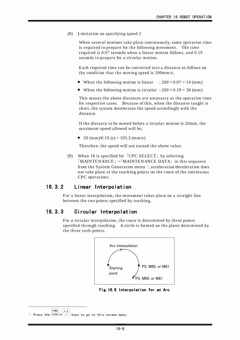
CHAPTER 16 ROBOT OPERATION
16-8
(8) Limitation on specifying speed 2
When several motions take place continuously, some operation timeis required to prepare for the following movement. The timerequired is 0.07 seconds when a linear motion follows, and 0.19seconds to prepare for a circular motion.
Each required time can be converted into a distance as follows onthe condition that the moving speed is 200mm/s;
• When the following motion is linear : 200×0.07 = 14 (mm)
• When the following motion is circular : 200×0.19 = 38 (mm)
This means the above distances are necessary as the operation timefor respective cases. Because of this, when the distance taught isshort, the system decelerates the speed accordingly with thedistance.
If the distance to be moved before a circular motion is 20mm, themaximum speed allowed will be,
• 20 (mm)/0.19 (s) = 105.3 (mm/s)
Therefore, the speed will not exceed the above value.
(9) When 16 is specified for 「CPC SELECT」 by selecting「MAINTENANCE」→「MAINTENANCE DATA」 in this sequencefrom the System Generation menu i, acceleration/deceleration doesnot take place at the teaching points on the route of the continuousCPC operations.
16.3.216.3.216.3.216.3.2 Linear InterpolationLinear InterpolationLinear InterpolationLinear Interpolation
For a linear interpolation, the movement takes place on a straight linebetween the two points specified by teaching.
16.3.316.3.316.3.316.3.3 Circular InterpolationCircular InterpolationCircular InterpolationCircular Interpolation
For a circular interpolation, the route is determined by three pointsspecified through teaching. A circle is formed on the plane determined bythe three such points.
Starting
point
P2, M80, or M81
P3, M80, or M81
Arc interpolation
Fig.16.Fig.16.Fig.16.Fig.16.8888 Interpolation for an Arc Interpolation for an Arc Interpolation for an Arc Interpolation for an Arc
i: Press the FUNC
HIGH+s.g
7 keys to go to this screen menu.
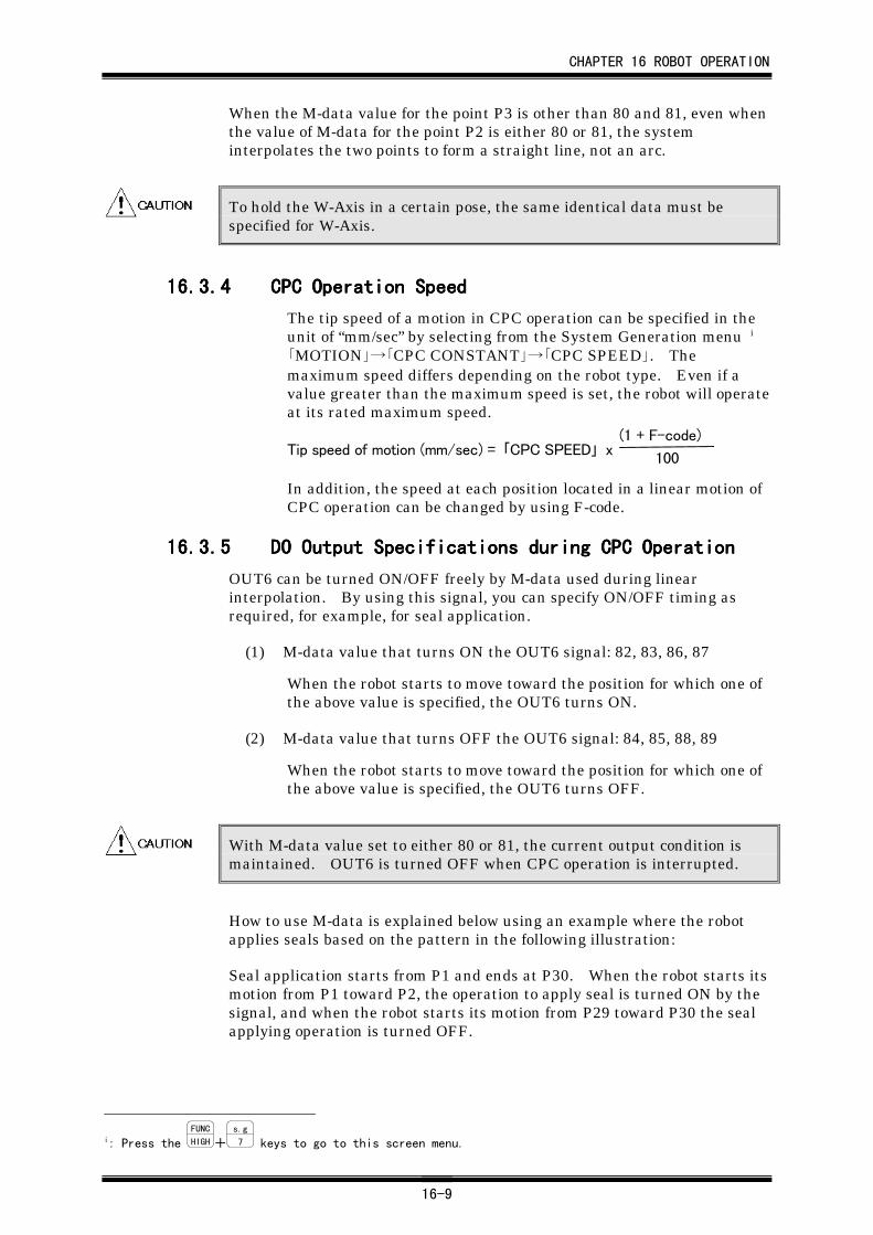
CHAPTER 16 ROBOT OPERATION
16-9
When the M-data value for the point P3 is other than 80 and 81, even whenthe value of M-data for the point P2 is either 80 or 81, the systeminterpolates the two points to form a straight line, not an arc.
To hold the W-Axis in a certain pose, the same identical data must bespecified for W-Axis.
16.3.416.3.416.3.416.3.4 CPC Operation SpeedCPC Operation SpeedCPC Operation SpeedCPC Operation Speed
The tip speed of a motion in CPC operation can be specified in theunit of “mm/sec” by selecting from the System Generation menu i
「MOTION」→「CPC CONSTANT」→「CPC SPEED」. Themaximum speed differs depending on the robot type. Even if avalue greater than the maximum speed is set, the robot will operateat its rated maximum speed.
Tip speed of motion (mm/sec) = 「CPC SPEED」 x(1 + F-code)
100
In addition, the speed at each position located in a linear motion ofCPC operation can be changed by using F-code.
16.3.516.3.516.3.516.3.5 DO Output Specifications during CPC OperationDO Output Specifications during CPC OperationDO Output Specifications during CPC OperationDO Output Specifications during CPC Operation
OUT6 can be turned ON/OFF freely by M-data used during linearinterpolation. By using this signal, you can specify ON/OFF timing asrequired, for example, for seal application.
(1) M-data value that turns ON the OUT6 signal: 82, 83, 86, 87
When the robot starts to move toward the position for which one ofthe above value is specified, the OUT6 turns ON.
(2) M-data value that turns OFF the OUT6 signal: 84, 85, 88, 89
When the robot starts to move toward the position for which one ofthe above value is specified, the OUT6 turns OFF.
With M-data value set to either 80 or 81, the current output condition ismaintained. OUT6 is turned OFF when CPC operation is interrupted.
How to use M-data is explained below using an example where the robotapplies seals based on the pattern in the following illustration:
Seal application starts from P1 and ends at P30. When the robot starts itsmotion from P1 toward P2, the operation to apply seal is turned ON by thesignal, and when the robot starts its motion from P29 toward P30 the sealapplying operation is turned OFF.
i: Press the FUNC
HIGH+s.g
7 keys to go to this screen menu.
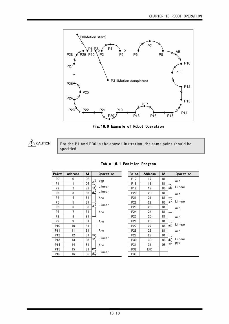
CHAPTER 16 ROBOT OPERATION
16-10
P1
P0(Motion start)
P2
P3
P4
P5 P6
P7
P8A9
P10
P11
P12
P13
P14P15P16
P17
P18
P19
P20
P21P22P23
P24
P25
P26
P27
P28 P29
P31(Motion completes)
P30
Fig.16.Fig.16.Fig.16.Fig.16.9999 Example of Robot Operation Example of Robot Operation Example of Robot Operation Example of Robot Operation
For the P1 and P30 in the above illustration, the same point should bespecified.
TableTableTableTable 16.16.16.16.1111 Position Program Position Program Position Program Position Program
PointPointPointPoint AddressAddressAddressAddress MMMM OperationOperationOperationOperation PointPointPointPoint AddressAddressAddressAddress MMMM OperationOperationOperationOperation
P0 0 02 P17 17 81
P1 1 04 P18 18 81
P2 2 82 P19 19 86
P3 3 86 P20 20 81
P4 4 81 P21 21 81
P5 5 81 P22 22 86
P6 6 86 P23 23 81
P7 7 81 P24 24 81
P8 8 81 P25 25 81
P9 9 81 P26 26 81
P10 10 81 P27 27 86
P11 11 81 P28 28 81
P12 12 81 P29 29 81
P13 13 86 P30 30 88
P14 14 81 P31 31 08
P15 15 81 P32 END
P16 16 86 P33
PTP
Linear
Linear
Arc
Linear
Arc
Arc
Arc
Linear
Arc
Linear
Arc
Linear
Arc
Linear
Arc
Arc
Linear
Arc
Linear
PTP
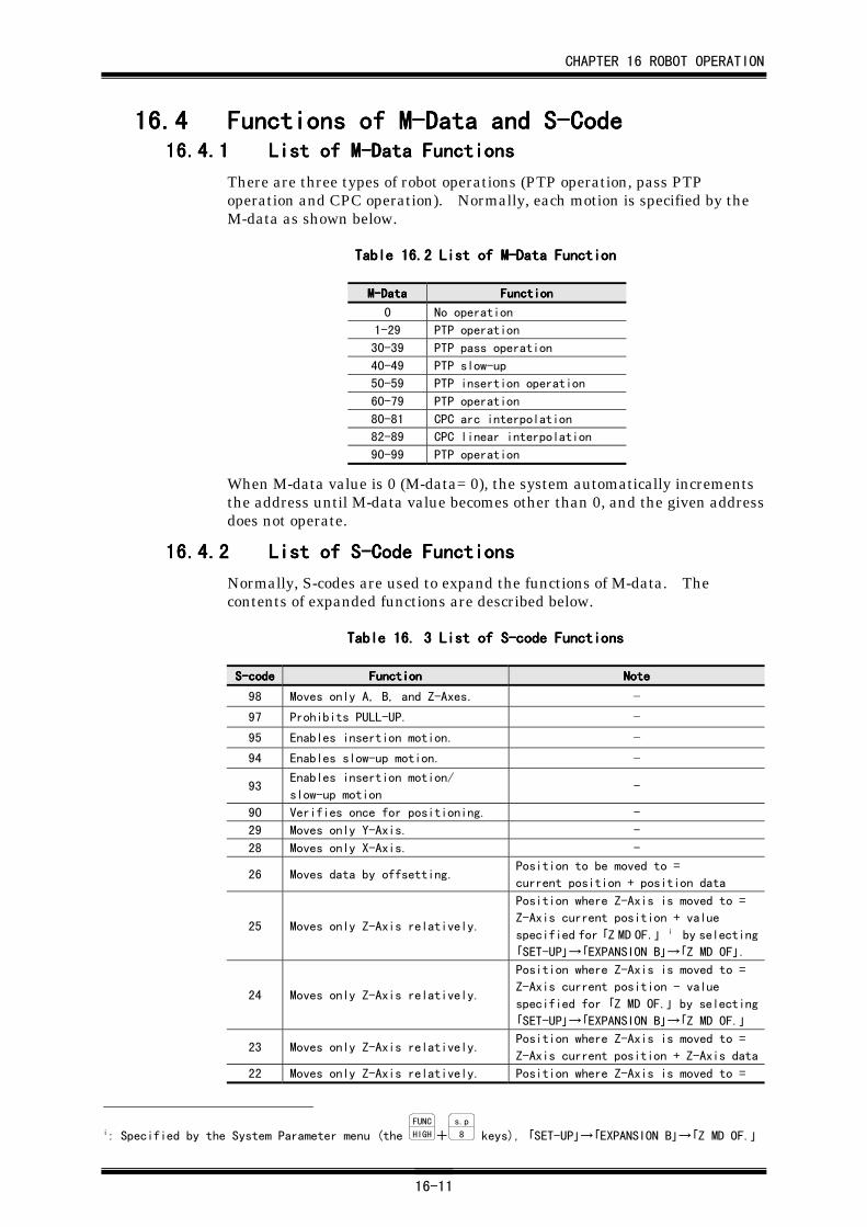
CHAPTER 16 ROBOT OPERATION
16-11
16.416.416.416.4 Functions of M-Data and S-CodeFunctions of M-Data and S-CodeFunctions of M-Data and S-CodeFunctions of M-Data and S-Code16.4.116.4.116.4.116.4.1 List of M-Data FunctionsList of M-Data FunctionsList of M-Data FunctionsList of M-Data Functions
There are three types of robot operations (PTP operation, pass PTPoperation and CPC operation). Normally, each motion is specified by theM-data as shown below.
Table 16.Table 16.Table 16.Table 16.2222 List of M-Data Function List of M-Data Function List of M-Data Function List of M-Data Function
M-DataM-DataM-DataM-Data FunctionFunctionFunctionFunction
0 No operation
1-29 PTP operation
30-39 PTP pass operation
40-49 PTP slow-up
50-59 PTP insertion operation
60-79 PTP operation
80-81 CPC arc interpolation
82-89 CPC linear interpolation
90-99 PTP operation
When M-data value is 0 (M-data= 0), the system automatically incrementsthe address until M-data value becomes other than 0, and the given addressdoes not operate.
16.4.216.4.216.4.216.4.2 List of S-Code FunctionsList of S-Code FunctionsList of S-Code FunctionsList of S-Code Functions
Normally, S-codes are used to expand the functions of M-data. Thecontents of expanded functions are described below.
Table 16. Table 16. Table 16. Table 16. 3333 List of S-code Functions List of S-code Functions List of S-code Functions List of S-code Functions
S-codeS-codeS-codeS-code FunctionFunctionFunctionFunction NoteNoteNoteNote
98 Moves only A, B, and Z-Axes. -
97 Prohibits PULL-UP. -
95 Enables insertion motion. -
94 Enables slow-up motion. -
93Enables insertion motion/
slow-up motion-
90 Verifies once for positioning. -
29 Moves only Y-Axis. -
28 Moves only X-Axis. -
26 Moves data by offsetting.Position to be moved to =
current position + position data
25 Moves only Z-Axis relatively.
Position where Z-Axis is moved to =
Z-Axis current position + value
specified for 「Z MD OF.」 i by selecting
「SET-UP」→「EXPANSION B」→「Z MD OF」.
24 Moves only Z-Axis relatively.
Position where Z-Axis is moved to =
Z-Axis current position - value
specified for 「Z MD OF.」 by selecting
「SET-UP」→「EXPANSION B」→「Z MD OF.」
23 Moves only Z-Axis relatively.Position where Z-Axis is moved to =
Z-Axis current position + Z-Axis data
22 Moves only Z-Axis relatively. Position where Z-Axis is moved to =
i: Specified by the System Parameter menu (the FUNC
HIGH+s.p
8 keys), 「SET-UP」→「EXPANSION B」→「Z MD OF.」
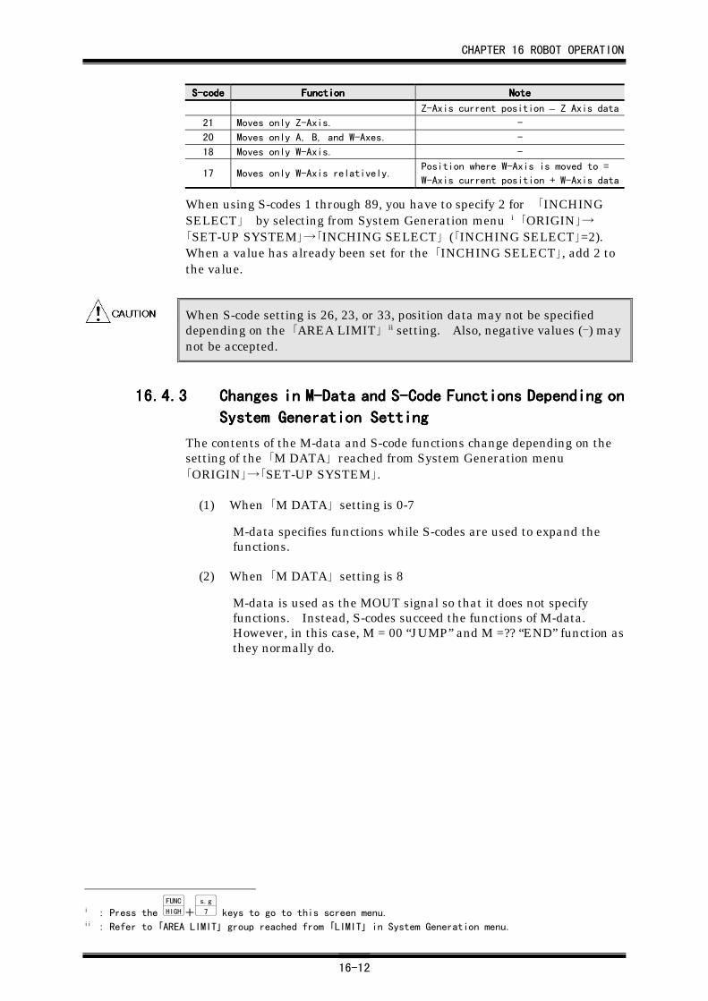
CHAPTER 16 ROBOT OPERATION
16-12
S-codeS-codeS-codeS-code FunctionFunctionFunctionFunction NoteNoteNoteNote
Z-Axis current position – Z Axis data21 Moves only Z-Axis. -
20 Moves only A, B, and W-Axes. -
18 Moves only W-Axis. -
17 Moves only W-Axis relatively.Position where W-Axis is moved to =
W-Axis current position + W-Axis data
When using S-codes 1 through 89, you have to specify 2 for 「INCHINGSELECT」 by selecting from System Generation menu i 「ORIGIN」→「SET-UP SYSTEM」→「INCHING SELECT」 (「INCHING SELECT」=2).When a value has already been set for the 「INCHING SELECT」, add 2 tothe value.
When S-code setting is 26, 23, or 33, position data may not be specifieddepending on the 「AREA LIMIT」 ii setting. Also, negative values (-) maynot be accepted.
16.4.316.4.316.4.316.4.3 Changes in M-Data and S-Code Functions Depending onChanges in M-Data and S-Code Functions Depending onChanges in M-Data and S-Code Functions Depending onChanges in M-Data and S-Code Functions Depending on
System Generation SettingSystem Generation SettingSystem Generation SettingSystem Generation Setting
The contents of the M-data and S-code functions change depending on thesetting of the 「M DATA」 reached from System Generation menu「ORIGIN」→「SET-UP SYSTEM」.
(1) When 「M DATA」 setting is 0-7
M-data specifies functions while S-codes are used to expand thefunctions.
(2) When 「M DATA」 setting is 8
M-data is used as the MOUT signal so that it does not specifyfunctions. Instead, S-codes succeed the functions of M-data.However, in this case, M = 00 “JUMP” and M =?? “END” function asthey normally do.
i : Press the FUNC
HIGH+s.g
7 keys to go to this screen menu.ii : Refer to 「AREA LIMIT」 group reached from 「LIMIT」 in System Generation menu.
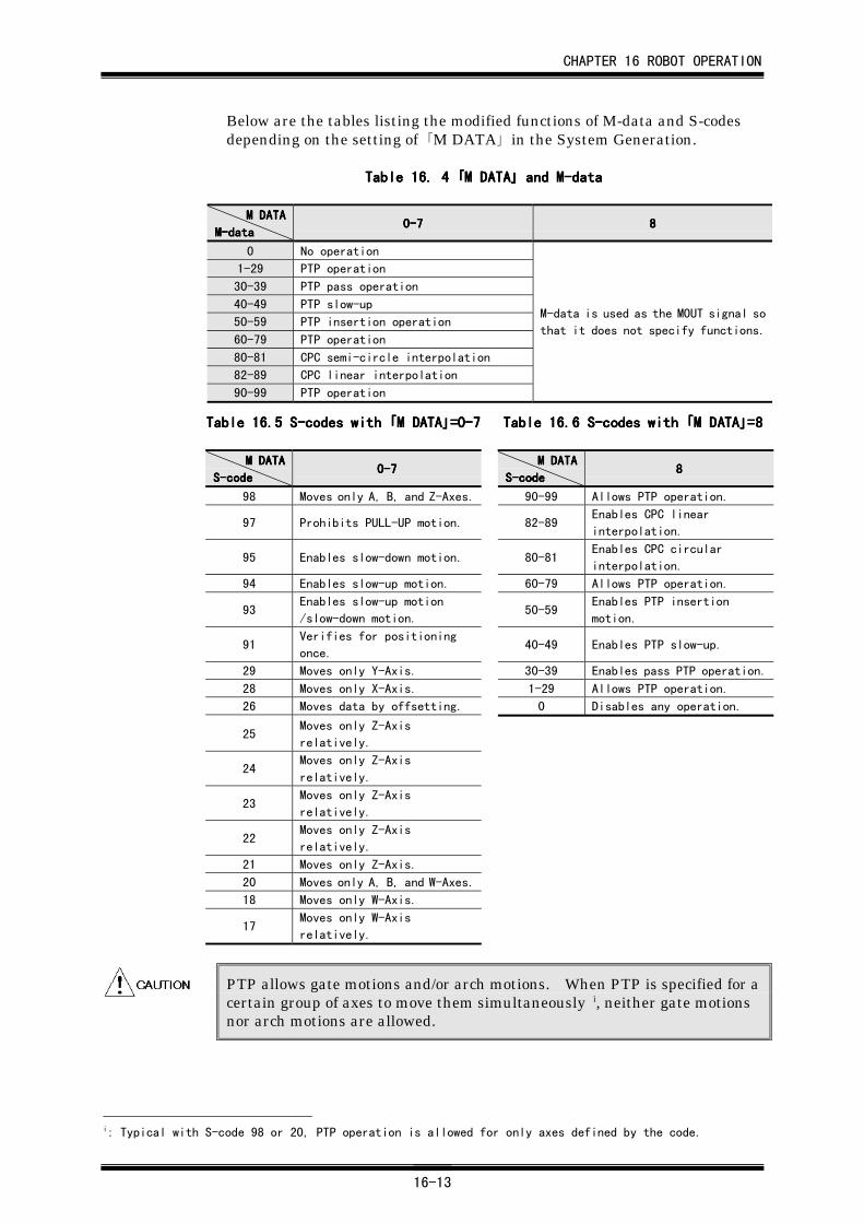
CHAPTER 16 ROBOT OPERATION
16-13
Below are the tables listing the modified functions of M-data and S-codesdepending on the setting of 「M DATA」 in the System Generation.
Table 16. Table 16. Table 16. Table 16. 4444 「「「「M DATAM DATAM DATAM DATA」」」」 and M-data and M-data and M-data and M-data
M DATAM DATAM DATAM DATA
M-dataM-dataM-dataM-data0-70-70-70-7 8888
0 No operation
1-29 PTP operation
30-39 PTP pass operation
40-49 PTP slow-up
50-59 PTP insertion operation
60-79 PTP operation
80-81 CPC semi-circle interpolation
82-89 CPC linear interpolation
90-99 PTP operation
M-data is used as the MOUT signal so
that it does not specify functions.
Table 16.Table 16.Table 16.Table 16.5555 S-codes with S-codes with S-codes with S-codes with 「「「「M DATAM DATAM DATAM DATA」」」」=0-7 =0-7 =0-7 =0-7 Table 16. Table 16. Table 16. Table 16.6666 S-codes with S-codes with S-codes with S-codes with 「「「「M DATAM DATAM DATAM DATA」」」」=8=8=8=8
M DATAM DATAM DATAM DATA
S-codeS-codeS-codeS-code0-70-70-70-7
M DATAM DATAM DATAM DATA
S-codeS-codeS-codeS-code8888
98 Moves only A, B, and Z-Axes. 90-99 Allows PTP operation.
97 Prohibits PULL-UP motion. 82-89Enables CPC linear
interpolation.
95 Enables slow-down motion. 80-81Enables CPC circular
interpolation.
94 Enables slow-up motion. 60-79 Allows PTP operation.
93Enables slow-up motion
/slow-down motion.50-59
Enables PTP insertion
motion.
91Verifies for positioning
once.40-49 Enables PTP slow-up.
29 Moves only Y-Axis. 30-39 Enables pass PTP operation.
28 Moves only X-Axis. 1-29 Allows PTP operation.
26 Moves data by offsetting. 0 Disables any operation.
25Moves only Z-Axis
relatively.
24Moves only Z-Axis
relatively.
23Moves only Z-Axis
relatively.
22Moves only Z-Axis
relatively.
21 Moves only Z-Axis.
20 Moves only A, B, and W-Axes.
18 Moves only W-Axis.
17Moves only W-Axis
relatively.
PTP allows gate motions and/or arch motions. When PTP is specified for acertain group of axes to move them simultaneously i, neither gate motionsnor arch motions are allowed.
i: Typical with S-code 98 or 20, PTP operation is allowed for only axes defined by the code.
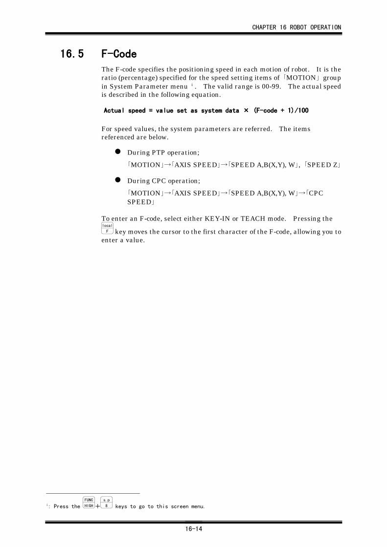
CHAPTER 16 ROBOT OPERATION
16-14
16.516.516.516.5 F-CodeF-CodeF-CodeF-CodeThe F-code specifies the positioning speed in each motion of robot. It is theratio (percentage) specified for the speed setting items of 「MOTION」 groupin System Parameter menu i . The valid range is 00-99. The actual speedis described in the following equation.
For speed values, the system parameters are referred. The itemsreferenced are below.
During PTP operation;
「MOTION」→「AXIS SPEED」→「SPEED A,B(X,Y), W」, 「SPEED Z」
During CPC operation;
「MOTION」→「AXIS SPEED」→「SPEED A,B(X,Y), W」→「CPCSPEED」
To enter an F-code, select either KEY-IN or TEACH mode. Pressing thelocal
F key moves the cursor to the first character of the F-code, allowing you toenter a value.
i: Press the FUNC
HIGH+s.p
8 keys to go to this screen menu.
Actual speed = value set as system data Actual speed = value set as system data Actual speed = value set as system data Actual speed = value set as system data ×××× (F-code + 1)/100 (F-code + 1)/100 (F-code + 1)/100 (F-code + 1)/100
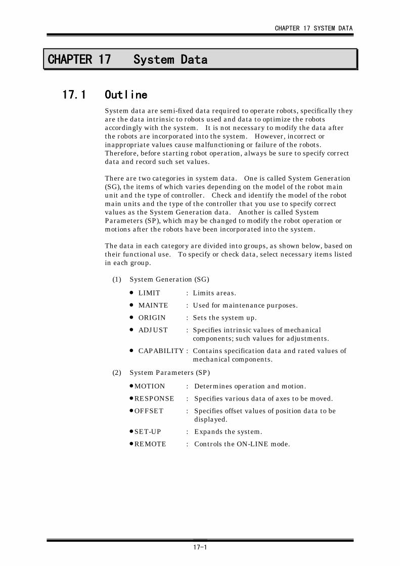
CHAPTER 17 SYSTEM DATA
17-1
CHAPTER 17CHAPTER 17CHAPTER 17CHAPTER 17 System DataSystem DataSystem DataSystem Data
17.117.117.117.1 OutlineOutlineOutlineOutlineSystem data are semi-fixed data required to operate robots, specifically theyare the data intrinsic to robots used and data to optimize the robotsaccordingly with the system. It is not necessary to modify the data afterthe robots are incorporated into the system. However, incorrect orinappropriate values cause malfunctioning or failure of the robots.Therefore, before starting robot operation, always be sure to specify correctdata and record such set values.
There are two categories in system data. One is called System Generation(SG), the items of which varies depending on the model of the robot mainunit and the type of controller. Check and identify the model of the robotmain units and the type of the controller that you use to specify correctvalues as the System Generation data. Another is called SystemParameters (SP), which may be changed to modify the robot operation ormotions after the robots have been incorporated into the system.
The data in each category are divided into groups, as shown below, based ontheir functional use. To specify or check data, select necessary items listedin each group.
(1) System Generation (SG)
• LIMIT : Limits areas.
• MAINTE : Used for maintenance purposes.
• ORIGIN : Sets the system up.
• ADJUST : Specifies intrinsic values of mechanicalcomponents; such values for adjustments.
• CAPABILITY : Contains specification data and rated values ofmechanical components.
(2) System Parameters (SP)
• MOTION : Determines operation and motion.
• RESPONSE : Specifies various data of axes to be moved.
• OFFSET : Specifies offset values of position data to bedisplayed.
• SET-UP : Expands the system.
• REMOTE : Controls the ON-LINE mode.
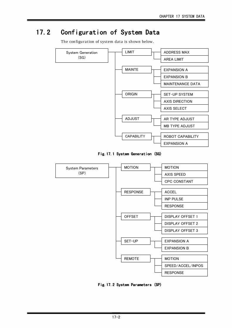
CHAPTER 17 SYSTEM DATA
17-2
17.217.217.217.2 Configuration of System DataConfiguration of System DataConfiguration of System DataConfiguration of System DataThe configuration of system data is shown below.
ADDRESS MAX
AREA LIMIT
EXPANSION A
EXPANSION B
MAINTENANCE DATA
SET-UP SYSTEM
AXIS DIRECTION
AXIS SELECT
AR TYPE ADJUST
MB TYPE ADJUST
ROBOT CAPABILITY
EXPANSION A
System Generation
(SG)
LIMIT
MAINTE
ORIGIN
ADJUST
CAPABILITY
Fig.17.Fig.17.Fig.17.Fig.17.1111 System Generation (SG) System Generation (SG) System Generation (SG) System Generation (SG)
MOTION
AXIS SPEED
CPC CONSTANT
ACCEL
INP PULSE
RESPONSE
DISPLAY OFFSET 1
DISPLAY OFFSET 2
DISPLAY OFFSET 3
EXPANSION A
EXPANSION B
MOTION
SPEED/ACCEL/INPOS
RESPONSE
System Parameters
(SP)
MOTION
RESPONSE
OFFSET
SET-UP
REMOTE
Fig.17.Fig.17.Fig.17.Fig.17.2222 System Parameters (SP) System Parameters (SP) System Parameters (SP) System Parameters (SP)
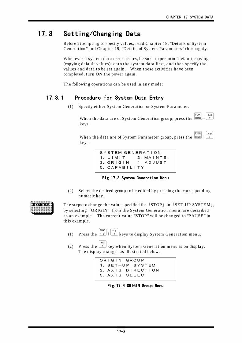
CHAPTER 17 SYSTEM DATA
17-3
17.317.317.317.3 Setting/Changing DataSetting/Changing DataSetting/Changing DataSetting/Changing DataBefore attempting to specify values, read Chapter 18, “Details of SystemGeneration” and Chapter 19, “Details of System Parameters” thoroughly.
Whenever a system data error occurs, be sure to perform “default copying(copying default values)” onto the system data first, and then specify thevalues and data to be set again. When these activities have beencompleted, turn ON the power again.
The following operations can be used in any mode:
17.3.117.3.117.3.117.3.1 Procedure for System Data EntryProcedure for System Data EntryProcedure for System Data EntryProcedure for System Data Entry
(1) Specify either System Generation or System Parameter.
When the data are of System Generation group, press the FUNC
HIGH+s.g
7
keys.
When the data are of System Parameter group, press the FUNC
HIGH+s.p
8
keys.
SYSTEM GENERATION1.LIMIT 2.MAINTE.
3.ORIGIN 4.ADJUST
5.CAPABILITY
Fig.17.Fig.17.Fig.17.Fig.17.3333 System Generation Menu System Generation Menu System Generation Menu System Generation Menu
(2) Select the desired group to be edited by pressing the correspondingnumeric key.
The steps to change the value specified for 「STOP」 in 「SET-UP SYSTEM」,by selecting 「ORIGIN」 from the System Generation menu, are describedas an example. The current value “STOP” will be changed to “PAUSE” inthis example.
(1) Press the FUNC
HIGH+s.g
7 keys to display System Generation menu.
(2) Press the mot
3 key when System Generation menu is on display.The display changes as illustrated below.
ORIGIN GROUP
1.SET-UP SYSTEM
2.AXIS DIRECTION
3.AXIS SELECT
Fig.17.Fig.17.Fig.17.Fig.17.4444 ORIGIN Group Menu ORIGIN Group Menu ORIGIN Group Menu ORIGIN Group Menu
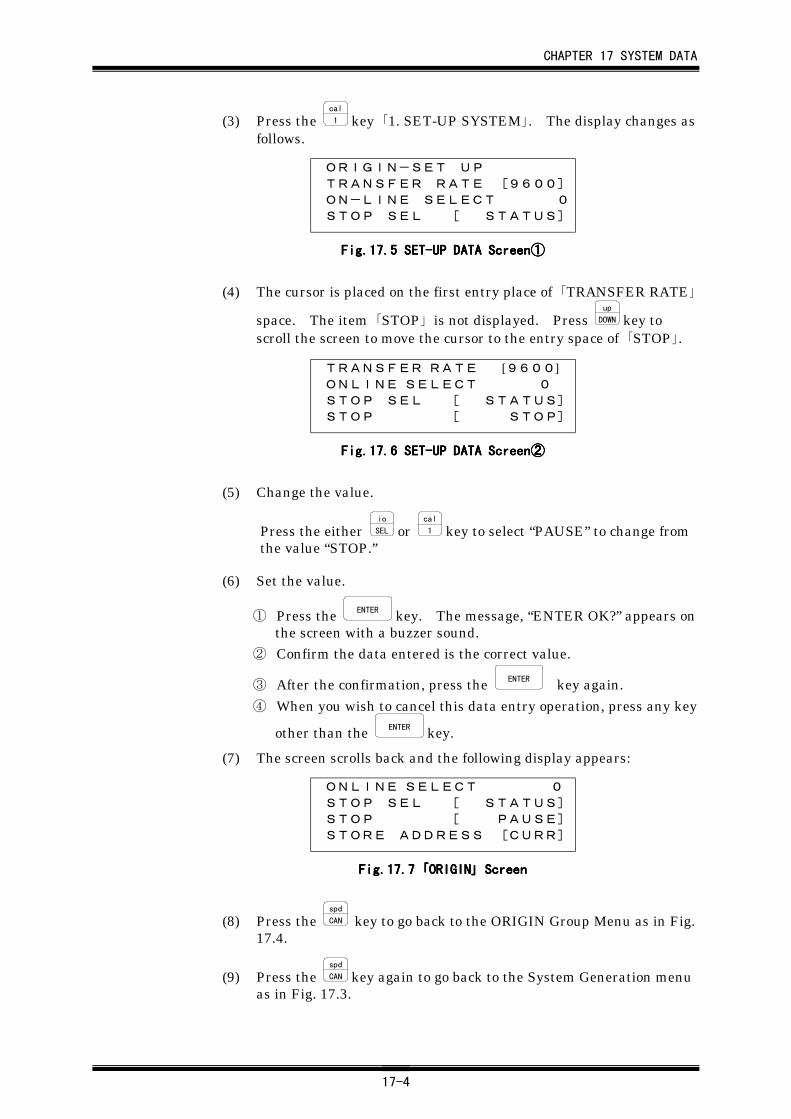
CHAPTER 17 SYSTEM DATA
17-4
(3) Press the cal
1 key 「1. SET-UP SYSTEM」. The display changes asfollows.
ORIGIN-SET UPTRANSFER RATE [9600]ON-LINE SELECT 0STOP SEL [ STATUS]
Fig.17.Fig.17.Fig.17.Fig.17.5555 SET-UP DATA Screen SET-UP DATA Screen SET-UP DATA Screen SET-UP DATA Screen①①①①
(4) The cursor is placed on the first entry place of 「TRANSFER RATE」
space. The item 「STOP」 is not displayed. Press up
DOWN key toscroll the screen to move the cursor to the entry space of 「STOP」.
TRANSFER RATE [9600]ONLINE SELECT 0STOP SEL [ STATUS]STOP [ STOP]
Fig.17.Fig.17.Fig.17.Fig.17.6666 SET-UP DATA Screen SET-UP DATA Screen SET-UP DATA Screen SET-UP DATA Screen②②②②
(5) Change the value.
Press the either io
SEL or cal
1 key to select “PAUSE” to change fromthe value “STOP.”
(6) Set the value.
① Press the ENTER key. The message, “ENTER OK?” appears onthe screen with a buzzer sound.
② Confirm the data entered is the correct value.
③ After the confirmation, press the ENTER key again.
④ When you wish to cancel this data entry operation, press any key
other than the ENTER key.
(7) The screen scrolls back and the following display appears:
ONLINE SELECT 0STOP SEL [ STATUS]STOP [ PAUSE]STORE ADDRESS [CURR]
Fig.17.Fig.17.Fig.17.Fig.17.7777 「「「「ORIGINORIGINORIGINORIGIN」」」」 Screen Screen Screen Screen
(8) Press the spd
CAN key to go back to the ORIGIN Group Menu as in Fig.17.4.
(9) Press the spd
CAN key again to go back to the System Generation menuas in Fig. 17.3.
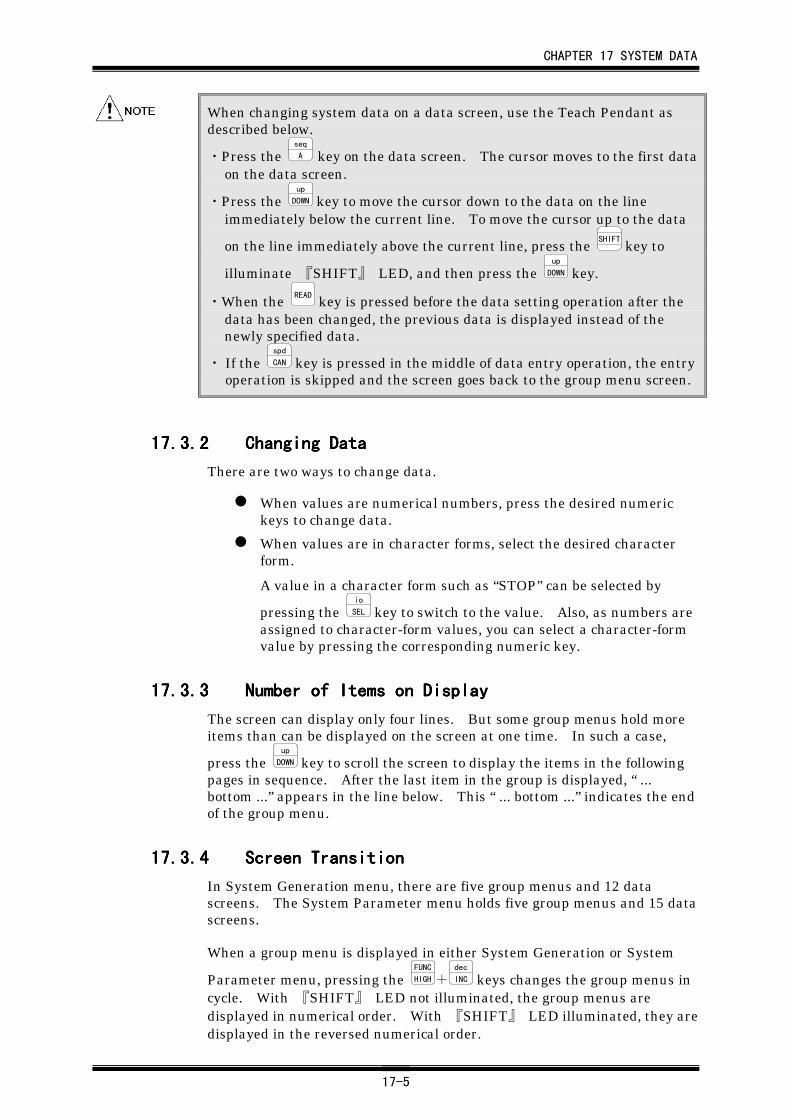
CHAPTER 17 SYSTEM DATA
17-5
When changing system data on a data screen, use the Teach Pendant asdescribed below.
・Press the seq
A key on the data screen. The cursor moves to the first dataon the data screen.
・Press the up
DOWN key to move the cursor down to the data on the lineimmediately below the current line. To move the cursor up to the data
on the line immediately above the current line, press the SHIFT
key to
illuminate 『SHIFT』 LED, and then press the up
DOWN key.
・When the READ key is pressed before the data setting operation after thedata has been changed, the previous data is displayed instead of thenewly specified data.
・ If the spd
CAN key is pressed in the middle of data entry operation, the entryoperation is skipped and the screen goes back to the group menu screen.
17.3.217.3.217.3.217.3.2 Changing DataChanging DataChanging DataChanging Data
There are two ways to change data.
When values are numerical numbers, press the desired numerickeys to change data.
When values are in character forms, select the desired characterform.
A value in a character form such as “STOP” can be selected by
pressing the io
SEL key to switch to the value. Also, as numbers areassigned to character-form values, you can select a character-formvalue by pressing the corresponding numeric key.
17.3.317.3.317.3.317.3.3 Number of Items on DisplayNumber of Items on DisplayNumber of Items on DisplayNumber of Items on Display
The screen can display only four lines. But some group menus hold moreitems than can be displayed on the screen at one time. In such a case,
press the up
DOWN key to scroll the screen to display the items in the followingpages in sequence. After the last item in the group is displayed, “ ...bottom ...” appears in the line below. This “ ... bottom ...” indicates the endof the group menu.
17.3.417.3.417.3.417.3.4 Screen TransitionScreen TransitionScreen TransitionScreen Transition
In System Generation menu, there are five group menus and 12 datascreens. The System Parameter menu holds five group menus and 15 datascreens.
When a group menu is displayed in either System Generation or System
Parameter menu, pressing the FUNC
HIGH+dec
INC keys changes the group menus incycle. With 『SHIFT』 LED not illuminated, the group menus aredisplayed in numerical order. With 『SHIFT』 LED illuminated, they aredisplayed in the reversed numerical order.
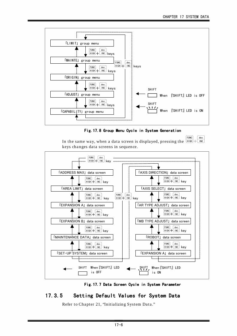
CHAPTER 17 SYSTEM DATA
17-6
「LIMIT」 group menu
「MAINTE」 group menu
「ORIGIN」 group menu
「ADJUST」 group menu
「CAPABILITY」 group menu
FUNC
HIGH+dec
INC keys
FUNC
HIGH+dec
INC keys
FUNC
HIGH+dec
INC keys
FUNC
HIGH+dec
INC keys
FUNC
HIGH+dec
INC keys
When 『SHIFT』LED is ON
When 『SHIFT』LED is OFF
SHIFT
SHIFT
Fig.17.Fig.17.Fig.17.Fig.17.8888 Group Menu Cycle in System Generation Group Menu Cycle in System Generation Group Menu Cycle in System Generation Group Menu Cycle in System Generation
In the same way, when a data screen is displayed, pressing the FUNC
HIGH+dec
INC
keys changes data screens in sequence.
FUNC
HIGH+dec
INC key
FUNC
HIGH+dec
INC key
FUNC
HIGH+dec
INC key
FUNC
HIGH+dec
INC key
FUNC
HIGH+dec
INC key
FUNC
HIGH+dec
INC key
FUNC
HIGH+dec
INC key
FUNC
HIGH+dec
INC key
FUNC
HIGH+dec
INC key
FUNC
HIGH+dec
INC key
「ADDRESS MAX」 data screen
「AREA LIMIT」 data screen
「EXPANSION A」 data screen
「EXPANSION B」 data screen
「MAINTENANCE DATA」 data screen
「SET-UP SYSTEM」 data screen
「AXIS DIRECTION」 data screen
「AXIS SELECT」 data screen
「AR TYPE ADJUST」 data screen
「MB TYPE ADJUST」 data screen
「ROBOT」 data screen
「EXPANSION A」 data screen
FUNC
HIGH+dec
INC key
FUNC
HIGH+dec
INC key
When 『SHIFT』 LED
is ON
When 『SHIFT』 LED
is OFF
SHIFT SHIFT
Fig.17.7 Data Screen Cycle in System ParameterFig.17.7 Data Screen Cycle in System ParameterFig.17.7 Data Screen Cycle in System ParameterFig.17.7 Data Screen Cycle in System Parameter
17.3.517.3.517.3.517.3.5 Setting Default Values for System DataSetting Default Values for System DataSetting Default Values for System DataSetting Default Values for System Data
Refer to Chapter 21, “Initializing System Data.”
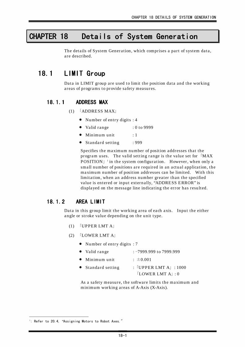
CHAPTER 18 DETAILS OF SYSTEM GENERATION
18-1
CHAPTER 18CHAPTER 18CHAPTER 18CHAPTER 18 Details of System GenerationDetails of System GenerationDetails of System GenerationDetails of System Generation
The details of System Generation, which comprises a part of system data,are described.
18.118.118.118.1 LIMIT GroupLIMIT GroupLIMIT GroupLIMIT GroupData in LIMIT group are used to limit the position data and the workingareas of programs to provide safety measures.
18.1.118.1.118.1.118.1.1 ADDRESS MAXADDRESS MAXADDRESS MAXADDRESS MAX
(1) 「ADDRESS MAX」
• Number of entry digits : 4
• Valid range : 0 to 9999
• Minimum unit : 1
• Standard setting : 999
Specifies the maximum number of position addresses that theprogram uses. The valid setting range is the value set for 「MAXPOSITION」 i in the system configuration. However, when only asmall number of positions are required in an actual application, themaximum number of position addresses can be limited. With thislimitation, when an address number greater than the specifiedvalue is entered or input externally, “ADDRESS ERROR” isdisplayed on the message line indicating the error has resulted.
18.1.218.1.218.1.218.1.2 AREA LIMITAREA LIMITAREA LIMITAREA LIMIT
Data in this group limit the working area of each axis. Input the eitherangle or stroke value depending on the unit type.
(1) 「UPPER LMT A」
(2) 「LOWER LMT A」
• Number of entry digits : 7
• Valid range : -7999.999 to 7999.999
• Minimum unit : ±0.001
• Standard setting : 「UPPER LMT A」 : 1000「LOWER LMT A」 : 0
As a safety measure, the software limits the maximum andminimum working areas of A-Axis (X-Axis).
i: Refer to 20.4, “Assigning Motors to Robot Axes."
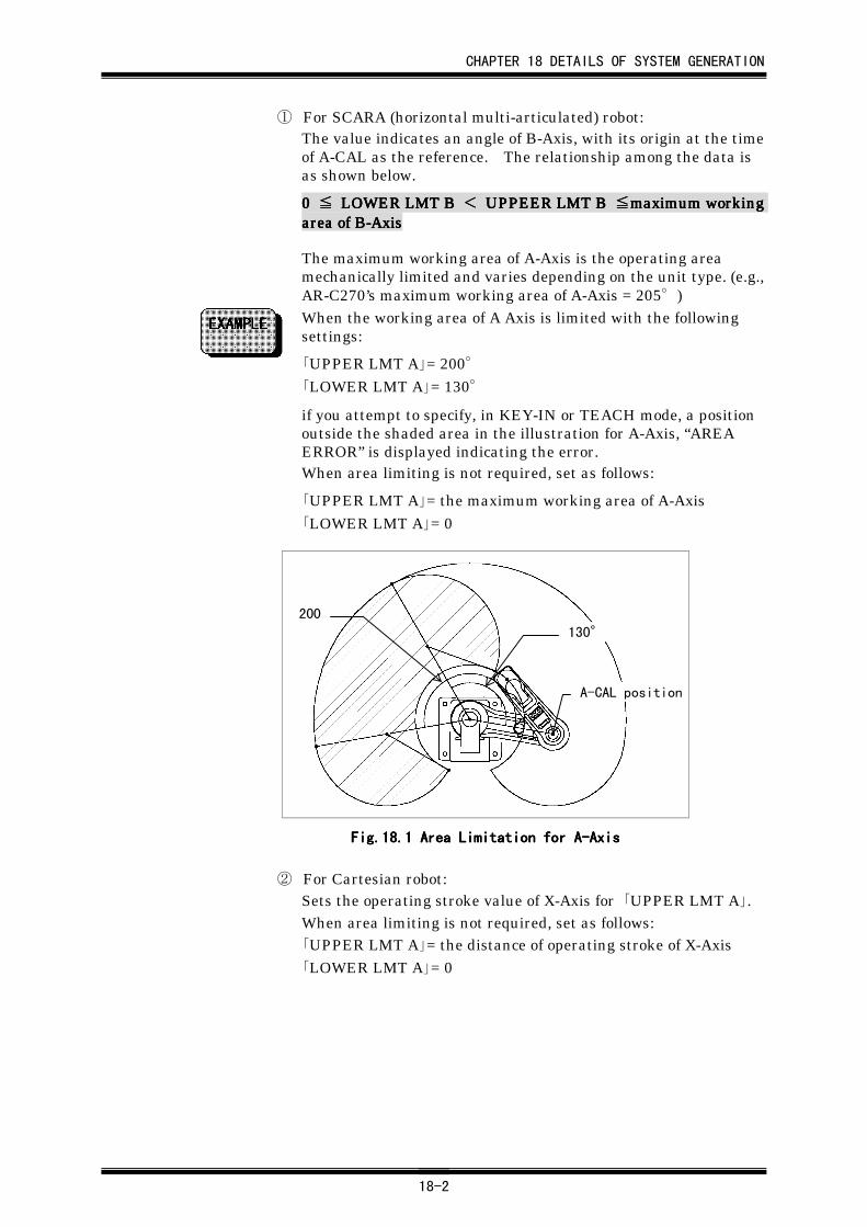
CHAPTER 18 DETAILS OF SYSTEM GENERATION
18-2
① For SCARA (horizontal multi-articulated) robot:The value indicates an angle of B-Axis, with its origin at the timeof A-CAL as the reference. The relationship among the data isas shown below.
0 0 0 0 ≦≦≦≦ LOWER LMT B LOWER LMT B LOWER LMT B LOWER LMT B <<<< UPPEER LMT B UPPEER LMT B UPPEER LMT B UPPEER LMT B ≦≦≦≦maximum workingmaximum workingmaximum workingmaximum workingarea of B-Axisarea of B-Axisarea of B-Axisarea of B-Axis
The maximum working area of A-Axis is the operating areamechanically limited and varies depending on the unit type. (e.g.,AR-C270’s maximum working area of A-Axis = 205°)When the working area of A Axis is limited with the followingsettings:
「UPPER LMT A」= 200°「LOWER LMT A」= 130°
if you attempt to specify, in KEY-IN or TEACH mode, a positionoutside the shaded area in the illustration for A-Axis, “AREAERROR” is displayed indicating the error.When area limiting is not required, set as follows:
「UPPER LMT A」= the maximum working area of A-Axis「LOWER LMT A」= 0
130°
200
A-CAL position
Fig.18.Fig.18.Fig.18.Fig.18.1111 Area Limitation for A-Axis Area Limitation for A-Axis Area Limitation for A-Axis Area Limitation for A-Axis
② For Cartesian robot:Sets the operating stroke value of X-Axis for 「UPPER LMT A」.When area limiting is not required, set as follows:「UPPER LMT A」= the distance of operating stroke of X-Axis「LOWER LMT A」= 0
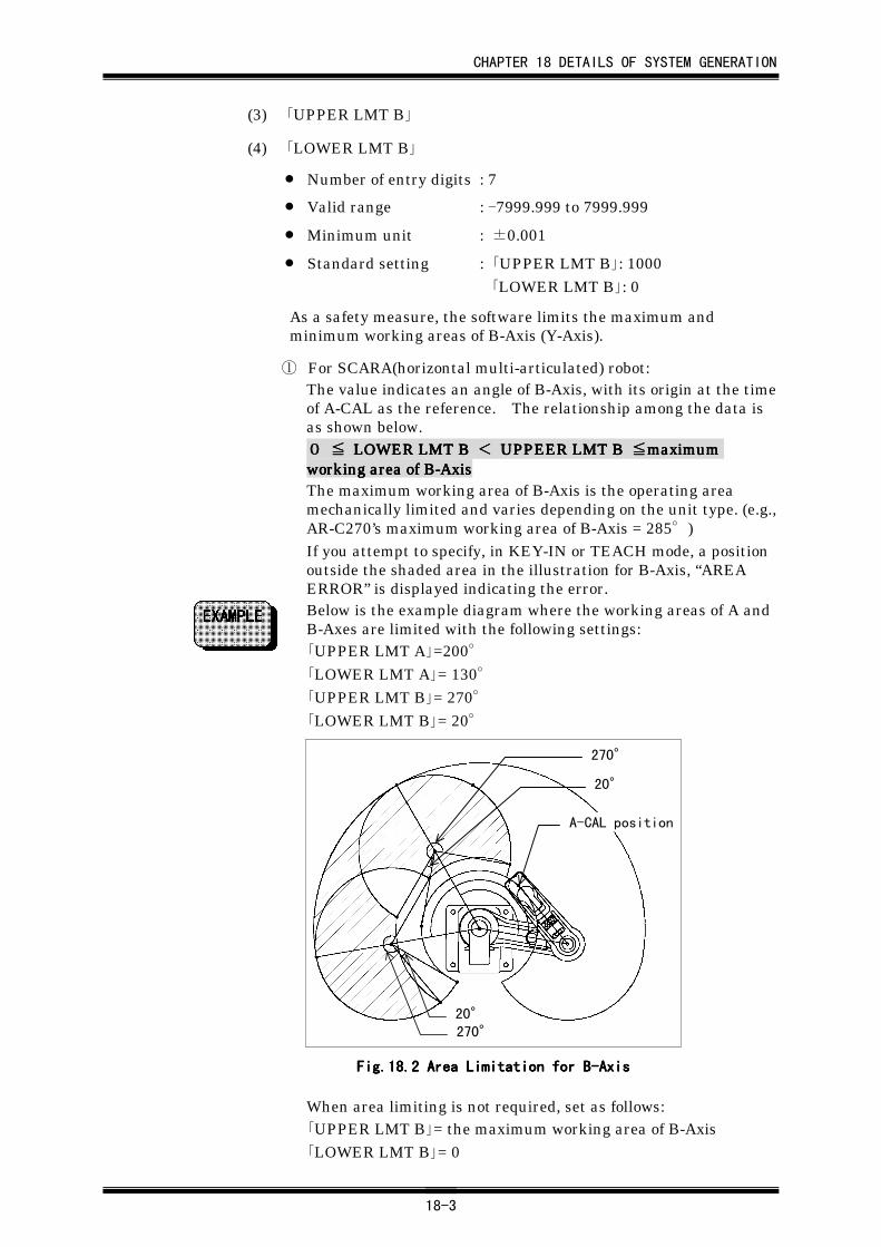
CHAPTER 18 DETAILS OF SYSTEM GENERATION
18-3
(3) 「UPPER LMT B」
(4) 「LOWER LMT B」
• Number of entry digits : 7
• Valid range : -7999.999 to 7999.999
• Minimum unit : ±0.001
• Standard setting : 「UPPER LMT B」: 1000 「LOWER LMT B」: 0
As a safety measure, the software limits the maximum andminimum working areas of B-Axis (Y-Axis).
① For SCARA(horizontal multi-articulated) robot:The value indicates an angle of B-Axis, with its origin at the timeof A-CAL as the reference. The relationship among the data isas shown below.0000 ≦≦≦≦ LOWER LMT B LOWER LMT B LOWER LMT B LOWER LMT B <<<< UPPEER LMT B UPPEER LMT B UPPEER LMT B UPPEER LMT B ≦≦≦≦maximummaximummaximummaximumworking area of B-Axisworking area of B-Axisworking area of B-Axisworking area of B-AxisThe maximum working area of B-Axis is the operating areamechanically limited and varies depending on the unit type. (e.g.,AR-C270’s maximum working area of B-Axis = 285°)If you attempt to specify, in KEY-IN or TEACH mode, a positionoutside the shaded area in the illustration for B-Axis, “AREAERROR” is displayed indicating the error.Below is the example diagram where the working areas of A andB-Axes are limited with the following settings:「UPPER LMT A」=200°「LOWER LMT A」= 130°「UPPER LMT B」= 270°「LOWER LMT B」= 20°
A-CAL position
270°
20°
270°
20°
Fig.18.Fig.18.Fig.18.Fig.18.2222 Area Limitation for B-Axis Area Limitation for B-Axis Area Limitation for B-Axis Area Limitation for B-Axis
When area limiting is not required, set as follows:「UPPER LMT B」= the maximum working area of B-Axis「LOWER LMT B」= 0
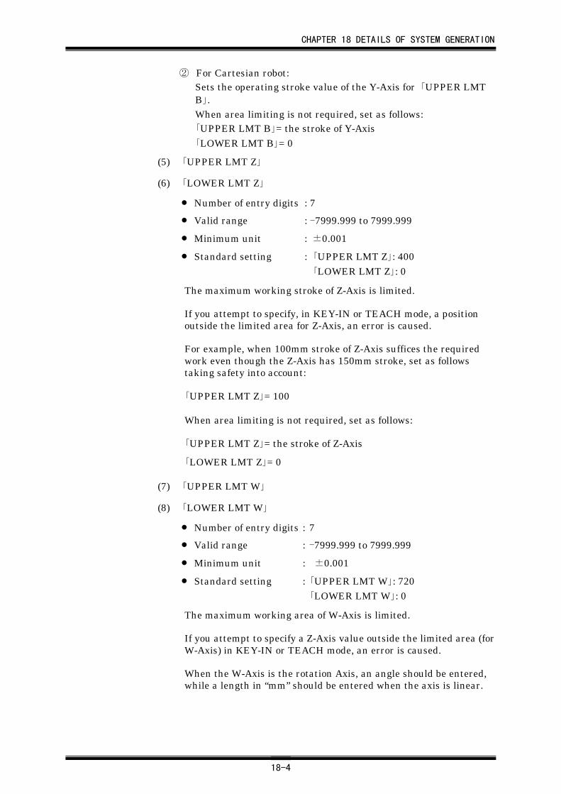
CHAPTER 18 DETAILS OF SYSTEM GENERATION
18-4
② For Cartesian robot:Sets the operating stroke value of the Y-Axis for 「UPPER LMTB」.When area limiting is not required, set as follows:「UPPER LMT B」= the stroke of Y-Axis「LOWER LMT B」= 0
(5) 「UPPER LMT Z」
(6) 「LOWER LMT Z」
• Number of entry digits : 7
• Valid range : -7999.999 to 7999.999
• Minimum unit : ±0.001
• Standard setting : 「UPPER LMT Z」: 400 「LOWER LMT Z」: 0
The maximum working stroke of Z-Axis is limited.
If you attempt to specify, in KEY-IN or TEACH mode, a positionoutside the limited area for Z-Axis, an error is caused.
For example, when 100mm stroke of Z-Axis suffices the requiredwork even though the Z-Axis has 150mm stroke, set as followstaking safety into account:
「UPPER LMT Z」= 100
When area limiting is not required, set as follows:
「UPPER LMT Z」= the stroke of Z-Axis
「LOWER LMT Z」= 0
(7) 「UPPER LMT W」
(8) 「LOWER LMT W」
• Number of entry digits : 7
• Valid range : -7999.999 to 7999.999
• Minimum unit : ±0.001
• Standard setting : 「UPPER LMT W」: 720「LOWER LMT W」: 0
The maximum working area of W-Axis is limited.
If you attempt to specify a Z-Axis value outside the limited area (forW-Axis) in KEY-IN or TEACH mode, an error is caused.
When the W-Axis is the rotation Axis, an angle should be entered,while a length in “mm” should be entered when the axis is linear.
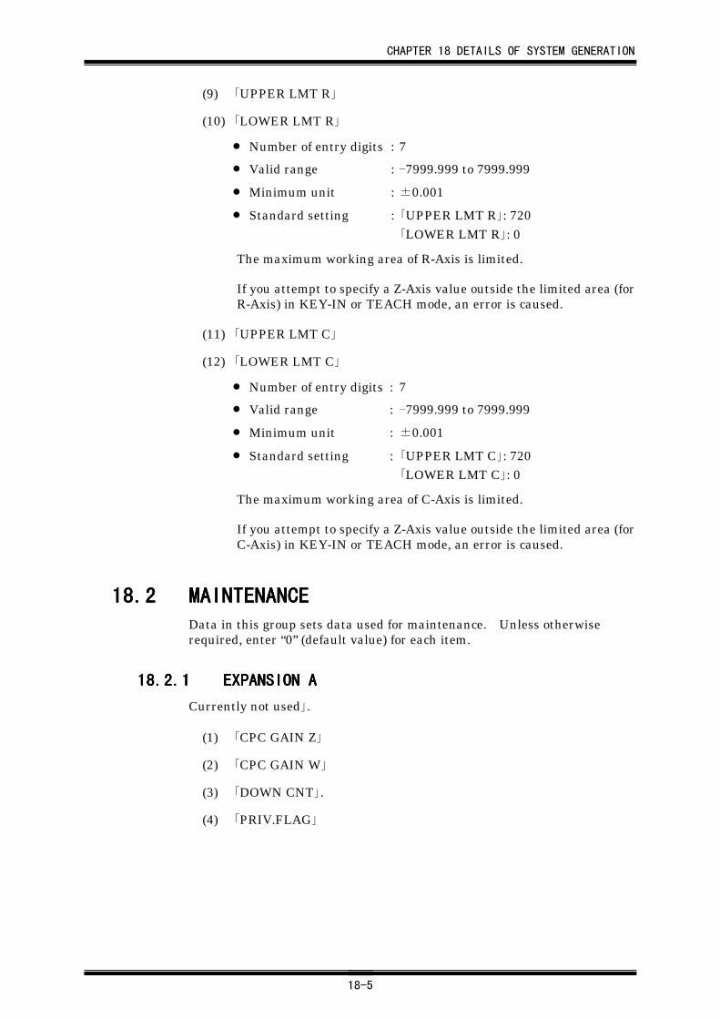
CHAPTER 18 DETAILS OF SYSTEM GENERATION
18-5
(9) 「UPPER LMT R」
(10) 「LOWER LMT R」
• Number of entry digits : 7
• Valid range : -7999.999 to 7999.999
• Minimum unit : ±0.001
• Standard setting : 「UPPER LMT R」: 720「LOWER LMT R」: 0
The maximum working area of R-Axis is limited.
If you attempt to specify a Z-Axis value outside the limited area (forR-Axis) in KEY-IN or TEACH mode, an error is caused.
(11) 「UPPER LMT C」
(12) 「LOWER LMT C」
• Number of entry digits : 7
• Valid range : -7999.999 to 7999.999
• Minimum unit : ±0.001
• Standard setting : 「UPPER LMT C」: 720「LOWER LMT C」: 0
The maximum working area of C-Axis is limited.
If you attempt to specify a Z-Axis value outside the limited area (forC-Axis) in KEY-IN or TEACH mode, an error is caused.
18.218.218.218.2 MAINTENANCEMAINTENANCEMAINTENANCEMAINTENANCEData in this group sets data used for maintenance. Unless otherwiserequired, enter “0” (default value) for each item.
18.2.118.2.118.2.118.2.1 EXPANSION AEXPANSION AEXPANSION AEXPANSION A
Currently not used」.
(1) 「CPC GAIN Z」
(2) 「CPC GAIN W」
(3) 「DOWN CNT」.
(4) 「PRIV.FLAG」
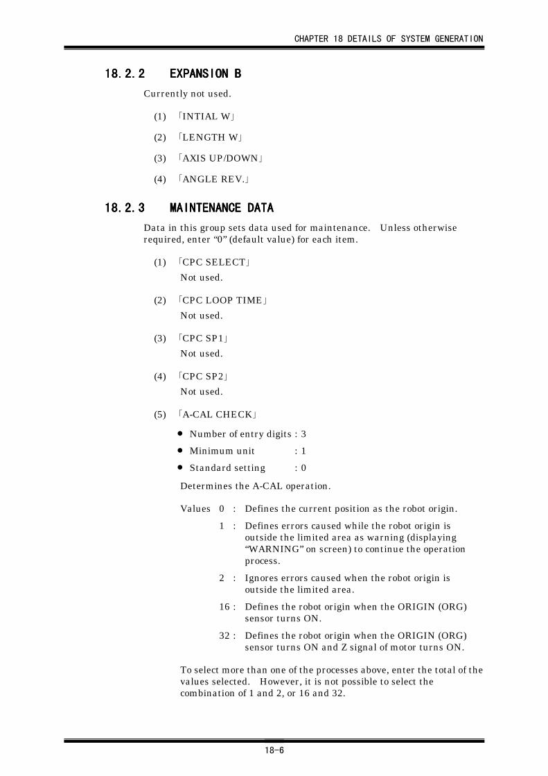
CHAPTER 18 DETAILS OF SYSTEM GENERATION
18-6
18.2.218.2.218.2.218.2.2 EXPANSION BEXPANSION BEXPANSION BEXPANSION B
Currently not used.
(1) 「INTIAL W」
(2) 「LENGTH W」
(3) 「AXIS UP/DOWN」
(4) 「ANGLE REV.」
18.2.318.2.318.2.318.2.3 MAINTENANCE DATAMAINTENANCE DATAMAINTENANCE DATAMAINTENANCE DATA
Data in this group sets data used for maintenance. Unless otherwiserequired, enter “0” (default value) for each item.
(1) 「CPC SELECT」
Not used.
(2) 「CPC LOOP TIME」
Not used.
(3) 「CPC SP1」
Not used.
(4) 「CPC SP2」
Not used.
(5) 「A-CAL CHECK」
• Number of entry digits : 3
• Minimum unit : 1
• Standard setting : 0
Determines the A-CAL operation.
Values 0 : Defines the current position as the robot origin.
1 : Defines errors caused while the robot origin isoutside the limited area as warning (displaying“WARNING” on screen) to continue the operationprocess.
2 : Ignores errors caused when the robot origin isoutside the limited area.
16 : Defines the robot origin when the ORIGIN (ORG)sensor turns ON.
32 : Defines the robot origin when the ORIGIN (ORG)sensor turns ON and Z signal of motor turns ON.
To select more than one of the processes above, enter the total of thevalues selected. However, it is not possible to select thecombination of 1 and 2, or 16 and 32.
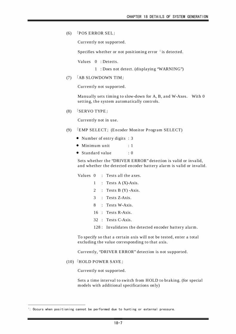
CHAPTER 18 DETAILS OF SYSTEM GENERATION
18-7
(6) 「POS ERROR SEL」
Currently not supported.
Specifies whether or not positioning error i is detected.
Values 0 : Detects.
1 : Does not detect. (displaying “WARNING”)
(7) 「AB SLOWDOWN TIM」
Currently not supported.
Manually sets timing to slow-down for A, B, and W-Axes. With 0setting, the system automatically controls.
(8) 「SERVO TYPE」
Currently not in use.
(9) 「EMP SELECT」 (Encoder Monitor Program SELECT)
• Number of entry digits : 3
• Minimum unit : 1
• Standard value : 0
Sets whether the “DRIVER ERROR” detection is valid or invalid,and whether the detected encoder battery alarm is valid or invalid.
Values 0 : Tests all the axes.
1 : Tests A (X)-Axis.
2 : Tests B (Y) -Axis.
3 : Tests Z-Axis.
8 : Tests W-Axis.
16 : Tests R-Axis.
32 : Tests C-Axis.
128 : Invalidates the detected encoder battery alarm.
To specify so that a certain axis will not be tested, enter a totalexcluding the value corresponding to that axis.
Currently, “DRIVER ERROR” detection is not supported.
(10) 「HOLD POWER SAVE」
Currently not supported.
Sets a time interval to switch from HOLD to braking. (for specialmodels with additional specifications only)
i: Occurs when positioning cannot be performed due to hunting or external pressure.
CHAPTER 18 DETAILS OF SYSTEM GENERATION
18-8
(11) 「Z SLOWDOWN TIM」
Currently not supported.
Manually sets timing to slow-down for Z-Axis. With 0 setting, thesystem automatically controls.
(12) 「STATION NO」
• Number of entry digits : 3
• Valid range : 0 to 999
• Minimum unit : 1
• Standard value : Robot No. (“1” for ROBOT 1)
Set a value when station No. should be specified for communication.
(13) 「SENSOR STOP SEL」
Currently not supported.
Changes the input logic of the W-Axis sensor when the sensor stops.
(14) 「SENSOR COUNT」
Currently not supported.
Changes the input detection amplitude of the W-Axis sensor whenthe sensor stops.
(15) 「PTP Z IN DATA」
Currently not in use.
(16) 「POSITIONING CNT」
Currently not in use.
18.318.318.318.3 ORIGINORIGINORIGINORIGINIn the ORIGIN group, you enter and set values and data mechanicallyintrinsic to robots. Failing to enter correct data for the items in this groupresults in irregular functioning in CPC operation and inaccuracy in databased on values on coordinates.
Also, this group contains data that determine, upon application, the basiccombinations of robots and motions.
CHAPTER 18 DETAILS OF SYSTEM GENERATION
18-9
18.3.118.3.118.3.118.3.1 SET-UP SYSTEMSET-UP SYSTEMSET-UP SYSTEMSET-UP SYSTEM
(1) 「TRANSFER RATE」
• Standard value : 9600 [bps]
Select the data transfer speed for RS-232C (selecting a character-form value).
When the value has been changed, turn OFF the power supply forcontroller power and then turn it ON again.
Select a value from the following:
・ 300 ・ 600
・ 1200 ・ 2400
・ 4800 ・ 9600
・ 19200 ・ 38400
(2) 「ON-LINE SELECT」
• Number of entry digit: 1
• Minimum unit: 1
• Standard value: 0
Values 0 : Standard
1 : Not in use.
2 : Uses the vision.
4 : Cancels the function of sequential speed acceleration i
to allow operation at the specified speed from thestart.
To use more than one of the above, enter the total of the valuesselected. For instance, to use vision and sequential speed-up,enter 6. To use speed-up function alone, enter 4.
(3) 「STOP SELECT」
• Standard value : STATUS
Selects a way for detecting STOP signal (IN5) when it is input.(selecting a character-form value)
Values STATUS : Detects the signal by status
RISING : Detects only the rising.
When “RISING” is selected for the above item, “STOP” must be selected forthe next item.
i: For the first three points, operation is carried out at a lower speed in standard condition. (first
point: 20% of the speed; second point: 40%; third point: 60%; fourth point: 100%)
CHAPTER 18 DETAILS OF SYSTEM GENERATION
18-10
(4) 「STOP」
• Standard value : STOP
Selects a function of the STOP signal (IN5). (selecting a character-form value)
Values STOP : Stops when STOP signal turns ON and restartswith START or NEXT signal input after STOPsignal (IN5) turns OFF.
PAUSE : Pauses while STOP signal (IN5) is ON.
(5) 「STORE ADDRESS」
• Standard value : NEXT
Selects an address to which the system returns upon recovery frompower interruption. (Selecting a character-form value)
Valid for AUTO mode of automatic operation. When power is shutdown during robot operation, for example, due to power failure,either the address where the system was operating the momentwhen the power was cut, or the next address is selected according tothe setting after the power supply is recovered.
Values NEXT : Selects the address next to the address wherepower was interrupted.
CURR : Selects the address where power wasinterrupted.
(6) 「I/O ASSIGNMENT」
• Number of entry digit : 1
• Minimum unit : 1
• Standard value : 0
Selects whether to use DI/DO as standard or as defined I/O. Touse this function, turn OFF the power after setting the value andturn ON the power again.
Values 0 : Standard
1 : Uses in ON-LINE mode all of the OUT 0-OUT 15 in thesame way as that in AUTO mode (outputting MOUT).
2 : A and B area output
4 : Base position output
8 : Outputs to an axis at the base position.
CHAPTER 18 DETAILS OF SYSTEM GENERATION
18-11
(7) 「INCHING SELECT」
• Number of entry digit : 1
• Minimum unit : 1
• Standard value : 0
Values 0 :
1 : Validates limitations on inching. When overrun orarea limit is input during inching, the inchingoperation is stopped.
2 : Uses special functions such as offsetting by a S-code(S-code: 1-89).
4 : Carries out linear inching i during inching in AUTOmode. (Invalidated when expanded interfaces areused.)
(8) 「M DATA」
• Number of entry digits : 2
• Valid range : 0 to 99
• Minimum unit : 1
• Standard value : 0
Sets definitions of use for M-data. For details, refer to 16.4.3,“Changes in M-data and S-code Functions Depending on SystemGeneration Setting.”
Values 0 : Sets the insertion motion, starting X, Y, and W-Axessimultaneously where M-data are in the fifties(M=50-59).
8 : Does not allow M-data to change operations/motions.Allows only S-codes to change operations/motions.
(9) 「AUTO/ON-LINE」
Specifies the mode to be used when ON-LINE operation is activated.(selecting a character-form value)
• Standard value : ON-LINE
Values ON-LINE : Uses ON-LINE mode.
AUTO : Uses AUTO mode.
EXT AUTO : Uses extended AUTO mode. Select thisvalue when 1000 or more position addressesare used.
Note that with “EXT AUTO,” DI/DO assignment changes. (Refer to7.2, “Extended AUTO Mode.”)
i: Normally axes are inched individually. When the linear inching is specified, inching operation takes
place on X-Y coordinates. Refer to 5.2.1, “Operation with X-Y Coordinates in LI-TEACH Mode."
CHAPTER 18 DETAILS OF SYSTEM GENERATION
18-12
(10) 「EMERGENCY STOP」
• Standard value: KEEP
The value is currently invalid. Normally the A-CAL is constantlyretained. Select either character-form value for A-CAL for
emergency stops. Press the io
SEL key to select.
Values KEEP : Retains the A-CAL.
RESET : Resets the A-CAL.
18.3.218.3.218.3.218.3.2 AXIS DIRECTIONAXIS DIRECTIONAXIS DIRECTIONAXIS DIRECTION
(1) 「A-CAL SEQ」
• Number of entry digits : 6
• Minimum unit : 111111
• Standard value : 221222
Specifies an order in which A-CAL is performed for the axes. Eachdigit corresponds to an axis as shown below.
000000
↓↓↓↓↓↓
ABZWRC
Enter the same value for axes for which A-CAL is performed at thesame time.
(2) 「A-CAL DIR. A」 : A-CAL direction for A-Axis (X-Axis).
(3) 「A-CAL DIR. B」 : A-CAL direction for B-Axis (Y-Axis).
(4) 「A-CAL DIR. Z」 : A-CAL direction for Z-Axis.
(5) 「A-CAL DIR. W」 : A-CAL direction for W-Axis.
(6) 「A-CAL DIR. R」 : A-CAL direction for R-Axis.
(7) 「A-CAL DIR. C」 : A-CAL direction for C-Axis.
• Standard value for the above : PLUS
Each item above changes the direction of A-CAL. (selecting acharacter-form value)
Values PLUS : Normal direction
MINUS : Reversed direction
Be sure to record the data specified for the above items after the robotinstallation.
CHAPTER 18 DETAILS OF SYSTEM GENERATION
18-13
(8) 「INCHI DIR. A」 : Inching direction for A-Axis (X-Axis)
(9) 「INCHI DIR. B」 : Inching direction for B-Axis (Y-Axis)
(10) 「INCHI DIR. Z」 : Inching direction for Z-Axis
(11) 「INCHI DIR. W」 : Inching direction for W-Axis
(12) 「INCHI DIR. R」 : Inching direction for R-Axis
(13) 「INCHI DIR. C」 : Inching direction for C-Axis
• Standard value for the above : PLUS
Each item above changes the direction of inching. (selecting acharacter-form value)
Values PLUS : Normal direction
MINUS : Reversed direction
18.3.318.3.318.3.318.3.3 AXIS SELECTAXIS SELECTAXIS SELECTAXIS SELECT
(1) 「A AXIS TYPE」: A-Axis (X-Axis)
(2) 「B AXIS TYPE」: B-Axis (Y-Axis)
(3) 「Z AXIS TYPE」: Z-Axis
(4) 「W AXIS TYPE」: W-Axis
(5) 「R AXIS TYPE」: R-Axis
(6) 「C AXIS TYPE」: C-Axis
• Standard value : USED
Specifies the status of the each axis, whether it is to be used or not.(selecting a character-form value)
Values NOT USED : Sets the non-use condition.
USED : Sets the use condition.
Be sure to record the data specified for the above items after the robotinstallation.
CHAPTER 18 DETAILS OF SYSTEM GENERATION
18-14
(7) 「A AXIS SEL」: Selects A-Axis (X-Axis).
(8) 「B AXIS SEL」: Selects B-Axis (Y-Axis).
(9) 「Z AXIS SEL」: Selects Z-Axis.
(10) 「W AXIS SEL」: Selects W-Axis.
(11) 「R AXIS SEL」: Selects R-Axis.
(12) 「C AXIS SEL」: Selects C-Axis.
• Standard value : USED
Each of the above values is currently invalid. Currently the axis isheld even if the setting is NOT HOLD. Select either character-form value for the axis.
Values NOT HOLD : Normal
HOLD : Constantly holds the axis.
Be sure to record the data specified for the above items after the robotinstallation.
18.418.418.418.4 ADJUSTADJUSTADJUSTADJUSTThe items in this group are used to set the values of the robot main unit.
18.4.118.4.118.4.118.4.1 AR TYPE ADJUSTAR TYPE ADJUSTAR TYPE ADJUSTAR TYPE ADJUST
(1) 「INITIAL A」
(2) 「INITIAL B」
(3) 「INITIAL Z」
(4) 「INITIAL W」
(5) 「INITIAL R」
(6) 「INITIAL C」
• Number of entry digits : 7
• Valid range : -7999.999 to 7999.999
• Minimum unit : ±0.001
Specifies the initial value of the robot. Normally, the positionwhere A-CAL is performed is specified as the origin. When youwish to move the origin from the originally given position to anotherposition, specify a value necessary for correction
Be sure to record the data specified for the above items after the robotinstallation.
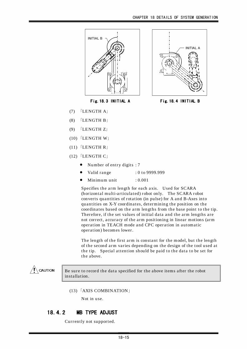
CHAPTER 18 DETAILS OF SYSTEM GENERATION
18-15
INITIAL A
INITIAL B
Fig.18.Fig.18.Fig.18.Fig.18.3333 INITIAL A INITIAL A INITIAL A INITIAL A Fig.18.Fig.18.Fig.18.Fig.18.4444 INITIALINITIALINITIALINITIAL B B B B
(7) 「LENGTH A」
(8) 「LENGTH B」
(9) 「LENGTH Z」
(10) 「LENGTH W」
(11) 「LENGTH R」
(12) 「LENGTH C」
• Number of entry digits : 7
• Valid range : 0 to 9999.999
• Minimum unit : 0.001
Specifies the arm length for each axis. Used for SCARA(horizontal multi-articulated) robot only. The SCARA robotconverts quantities of rotation (in pulse) for A and B-Axes intoquantities on X-Y coordinates, determining the position on thecoordinates based on the arm lengths from the base point to the tip.Therefore, if the set values of initial data and the arm lengths arenot correct, accuracy of the arm positioning in linear motions (armoperation in TEACH mode and CPC operation in automaticoperation) becomes lower.
The length of the first arm is constant for the model, but the lengthof the second arm varies depending on the design of the tool used atthe tip. Special attention should be paid to the data to be set forthe above.
Be sure to record the data specified for the above items after the robotinstallation.
(13) 「AXIS COMBINATION」
Not in use.
18.4.218.4.218.4.218.4.2 MB TYPE ADJUSTMB TYPE ADJUSTMB TYPE ADJUSTMB TYPE ADJUST
Currently not supported.
CHAPTER 18 DETAILS OF SYSTEM GENERATION
18-16
18.518.518.518.5 CAPABILITYCAPABILITYCAPABILITYCAPABILITYUse this group when checking the specifications of the robot main unit ormemory data intrinsic to the robot.
18.5.118.5.118.5.118.5.1 ROBOT CAPABILITYROBOT CAPABILITYROBOT CAPABILITYROBOT CAPABILITY
Displays the individual settings for the encoders. You cannot change thedata here.
(1) 「ENC. PULSE A」: Encoder pulse for A-Axis (X-Axis)
(2) 「ENC. PULSE B」: Encoder pulse for B-Axis (Y-Axis)
(3) 「ENC. PULSE Z」: Encoder pulse for Z-Axis
(4) 「ENC. PULSE W」: Encoder pulse for W-Axis
(5) 「ENC. PULSE R」: Encoder pulse for R-Axis
(6) 「ENC. PULSE C」: Encoder pulse for C-Axis
• Number of entry digits : 7
• Minimum unit : 1
Displays the encoder pulse set for each axis.
(7) 「LEAD/GEAR A」: Lead/gear setting for A-Axis (X-Axis)
(8) 「LEAD/GEAR B」: Lead/gear setting for B-Axis (Y-Axis)
(9) 「LEAD/GEAR Z」: Lead/gear setting for Z-Axis
(10) 「LEAD/GEAR W」: Lead/gear setting for W-Axis
(11) 「LEAD/GEAR R」: Lead/gear setting for R-Axis
(12) 「LEAD/GEAR C」: Lead/gear setting for C-Axis
• Number of entry digits : 6
• Minimum unit : 0.001
Displays the lead or gear ratio set for each axis.
(13) 「MOTER REV. A」: Maximum motor revolution speed for A-Axis (X-Axis)
(14) 「MOTER REV. B」: Maximum motor revolution speed for B-Axis (Y-Axis)
(15) 「MOTER REV. Z」: Maximum motor revolution speed for Z-Axis
(16) 「MOTER REV. W」: Maximum motor revolution speed for W-Axis
(17) 「MOTER REV. R」: Maximum motor revolution speed for R-Axis
(18) 「MOTER REV. C」: Maximum motor revolution speed for C-Axis
• Number of entry digits : 4
• Minimum unit : 1
Displays the maximum motor revolution speed set for each axis.
CHAPTER 18 DETAILS OF SYSTEM GENERATION
18-17
18.5.218.5.218.5.218.5.2 EXPANSION AEXPANSION AEXPANSION AEXPANSION A
The following data are system data for expansion to be specified whenapplicable data items are added. Therefore, specify “0” for the followingitems unless our company requests otherwise.
(1) 「EXPANSION 0」
(2) 「EXPANSION 1」
(3) 「EXPANSION 2」
(4) 「EXPANSION 3」
(5) 「EXPANSION 4」
(6) 「EXPANSION 5」
(7) 「EXPANSION 6」
(8) 「EXPANSION 7」
Not used.
(9) 「CPC INTEG GAIN」
Not used.
(10) 「FV TIME 0」
(11) 「FV TIME 1」
(12) 「FV TIME 2」
Not used.
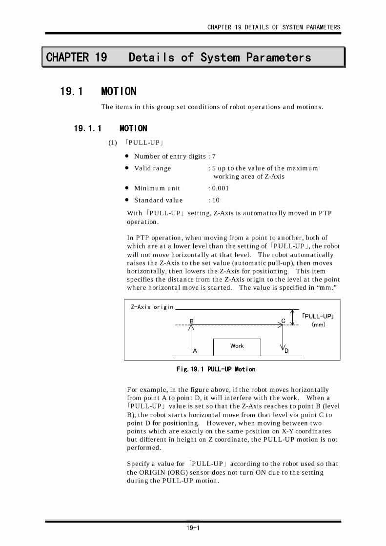
CHAPTER 19 DETAILS OF SYSTEM PARAMETERS
19-1
CHAPTER 19CHAPTER 19CHAPTER 19CHAPTER 19 Details of System ParametersDetails of System ParametersDetails of System ParametersDetails of System Parameters
19.119.119.119.1 MOTIONMOTIONMOTIONMOTIONThe items in this group set conditions of robot operations and motions.
19.1.119.1.119.1.119.1.1 MOTIONMOTIONMOTIONMOTION
(1) 「PULL-UP」
• Number of entry digits : 7
• Valid range : 5 up to the value of the maximumworking area of Z-Axis
• Minimum unit : 0.001
• Standard value : 10
With 「PULL-UP」 setting, Z-Axis is automatically moved in PTPoperation.
In PTP operation, when moving from a point to another, both ofwhich are at a lower level than the setting of 「PULL-UP」, the robotwill not move horizontally at that level. The robot automaticallyraises the Z-Axis to the set value (automatic pull-up), then moveshorizontally, then lowers the Z-Axis for positioning. This itemspecifies the distance from the Z-Axis origin to the level at the pointwhere horizontal move is started. The value is specified in “mm.”
「PULL-UP」
(mm)
WorkA
B C
D
Z-Axis origin
Fig.19.Fig.19.Fig.19.Fig.19.1111 PULL-UP Motion PULL-UP Motion PULL-UP Motion PULL-UP Motion
For example, in the figure above, if the robot moves horizontallyfrom point A to point D, it will interfere with the work. When a「PULL-UP」 value is set so that the Z-Axis reaches to point B (levelB), the robot starts horizontal move from that level via point C topoint D for positioning. However, when moving between twopoints which are exactly on the same position on X-Y coordinatesbut different in height on Z coordinate, the PULL-UP motion is notperformed.
Specify a value for 「PULL-UP」 according to the robot used so thatthe ORIGIN (ORG) sensor does not turn ON due to the settingduring the PULL-UP motion.
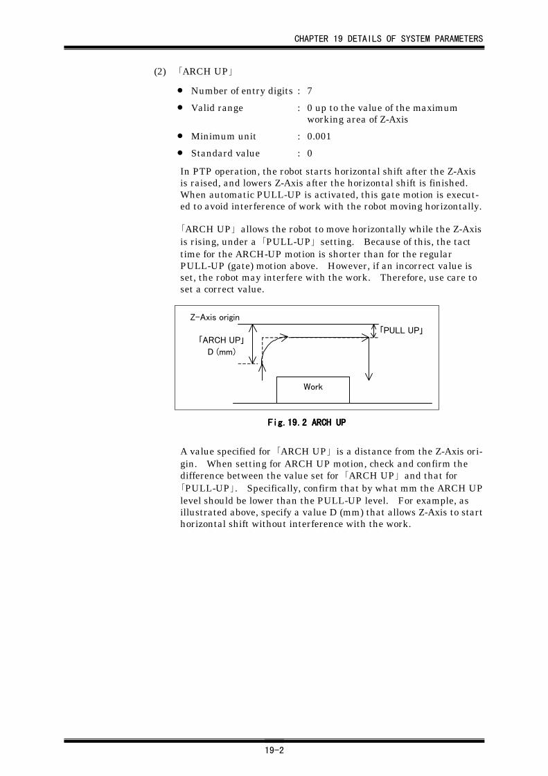
CHAPTER 19 DETAILS OF SYSTEM PARAMETERS
19-2
(2) 「ARCH UP」
• Number of entry digits : 7
• Valid range : 0 up to the value of the maximumworking area of Z-Axis
• Minimum unit : 0.001
• Standard value : 0
In PTP operation, the robot starts horizontal shift after the Z-Axisis raised, and lowers Z-Axis after the horizontal shift is finished.When automatic PULL-UP is activated, this gate motion is execut-ed to avoid interference of work with the robot moving horizontally.
「ARCH UP」 allows the robot to move horizontally while the Z-Axisis rising, under a 「PULL-UP」 setting. Because of this, the tacttime for the ARCH-UP motion is shorter than for the regularPULL-UP (gate) motion above. However, if an incorrect value isset, the robot may interfere with the work. Therefore, use care toset a correct value.
「PULL UP」
Work
「ARCH UP」
D (mm)
Z-Axis origin
Fig.19.Fig.19.Fig.19.Fig.19.2222 ARCH UP ARCH UP ARCH UP ARCH UP
A value specified for 「ARCH UP」 is a distance from the Z-Axis ori-gin. When setting for ARCH UP motion, check and confirm thedifference between the value set for 「ARCH UP」 and that for「PULL-UP」. Specifically, confirm that by what mm the ARCH UPlevel should be lower than the PULL-UP level. For example, asillustrated above, specify a value D (mm) that allows Z-Axis to starthorizontal shift without interference with the work.
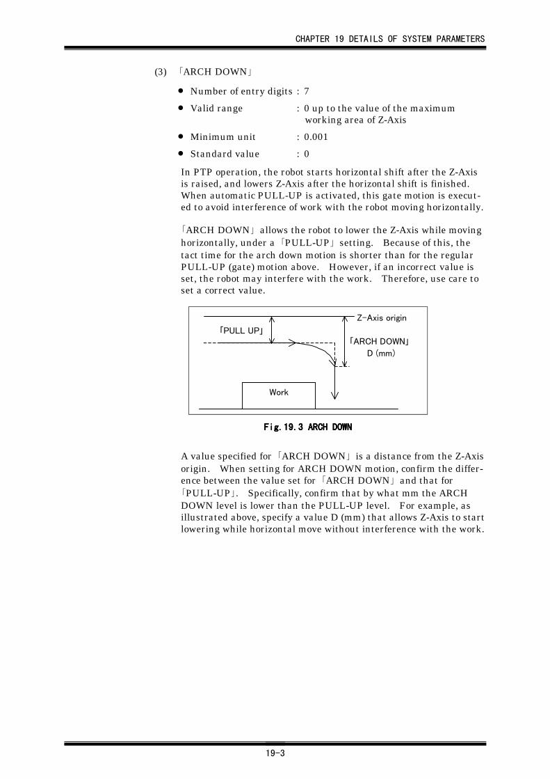
CHAPTER 19 DETAILS OF SYSTEM PARAMETERS
19-3
(3) 「ARCH DOWN」
• Number of entry digits : 7
• Valid range : 0 up to the value of the maximumworking area of Z-Axis
• Minimum unit : 0.001
• Standard value : 0
In PTP operation, the robot starts horizontal shift after the Z-Axisis raised, and lowers Z-Axis after the horizontal shift is finished.When automatic PULL-UP is activated, this gate motion is execut-ed to avoid interference of work with the robot moving horizontally.
「ARCH DOWN」 allows the robot to lower the Z-Axis while movinghorizontally, under a 「PULL-UP」 setting. Because of this, thetact time for the arch down motion is shorter than for the regularPULL-UP (gate) motion above. However, if an incorrect value isset, the robot may interfere with the work. Therefore, use care toset a correct value.
Work
「PULL UP」
Z-Axis origin
「ARCH DOWN」
D (mm)
Fig.19.Fig.19.Fig.19.Fig.19.3333 ARCH DOWN ARCH DOWN ARCH DOWN ARCH DOWN
A value specified for 「ARCH DOWN」 is a distance from the Z-Axisorigin. When setting for ARCH DOWN motion, confirm the differ-ence between the value set for 「ARCH DOWN」 and that for「PULL-UP」. Specifically, confirm that by what mm the ARCHDOWN level is lower than the PULL-UP level. For example, asillustrated above, specify a value D (mm) that allows Z-Axis to startlowering while horizontal move without interference with the work.
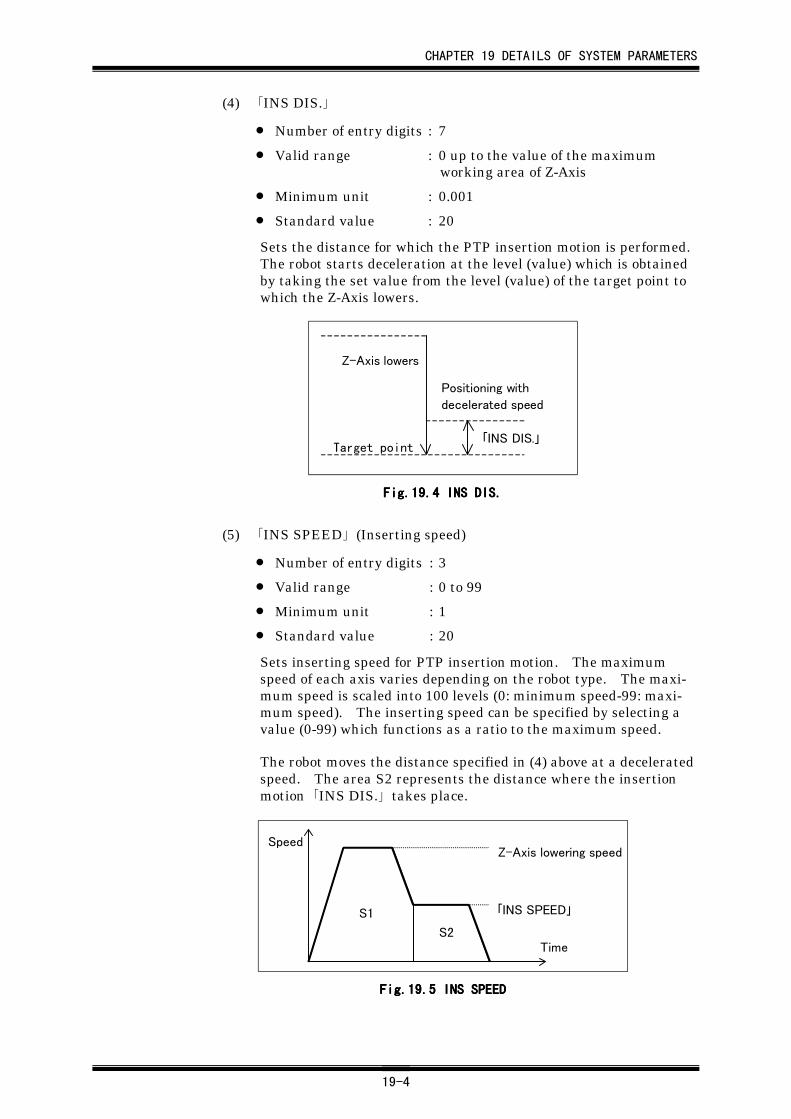
CHAPTER 19 DETAILS OF SYSTEM PARAMETERS
19-4
(4) 「INS DIS.」
• Number of entry digits : 7
• Valid range : 0 up to the value of the maximumworking area of Z-Axis
• Minimum unit : 0.001
• Standard value : 20
Sets the distance for which the PTP insertion motion is performed.The robot starts deceleration at the level (value) which is obtainedby taking the set value from the level (value) of the target point towhich the Z-Axis lowers.
「INS DIS.」
Z-Axis lowers
Positioning with
decelerated speed
Target point
Fig.19.Fig.19.Fig.19.Fig.19.4444 INS DIS. INS DIS. INS DIS. INS DIS.
(5) 「INS SPEED」 (Inserting speed)
• Number of entry digits : 3
• Valid range : 0 to 99
• Minimum unit : 1
• Standard value : 20
Sets inserting speed for PTP insertion motion. The maximumspeed of each axis varies depending on the robot type. The maxi-mum speed is scaled into 100 levels (0: minimum speed-99: maxi-mum speed). The inserting speed can be specified by selecting avalue (0-99) which functions as a ratio to the maximum speed.
The robot moves the distance specified in (4) above at a deceleratedspeed. The area S2 represents the distance where the insertionmotion 「INS DIS.」 takes place.
Speed
Time
S1
S2
Z-Axis lowering speed
「INS SPEED」
Fig.19.Fig.19.Fig.19.Fig.19.5555 INS SPEED INS SPEED INS SPEED INS SPEED
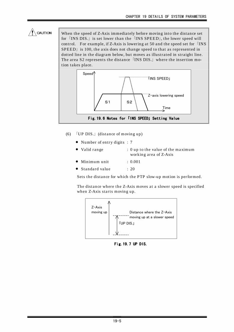
CHAPTER 19 DETAILS OF SYSTEM PARAMETERS
19-5
When the speed of Z-Axis immediately before moving into the distance setfor 「INS DIS.」 is set lower than the 「INS SPEED」, the lower speed willcontrol. For example, if Z-Axis is lowering at 50 and the speed set for 「INSSPEED」 is 100, the axis does not change speed to that as represented indotted line in the diagram below, but moves as illustrated in straight line.The area S2 represents the distance 「INS DIS.」 where the insertion mo-tion takes place.
Speed
Time
S1 S2
「INS SPEED」
Z-axis lowering speed
Fig.19.Fig.19.Fig.19.Fig.19.6666 Notes for Notes for Notes for Notes for 「「「「INS SPEEDINS SPEEDINS SPEEDINS SPEED」」」」 Setting Value Setting Value Setting Value Setting Value
(6) 「UP DIS.」 (distance of moving up)
• Number of entry digits : 7
• Valid range : 0 up to the value of the maximumworking area of Z-Axis
• Minimum unit : 0.001
• Standard value : 20
Sets the distance for which the PTP slow-up motion is performed.
The distance where the Z-Axis moves at a slower speed is specifiedwhen Z-Axis starts moving up.
「UP DIS.」
Z-Axis
moving up Distance where the Z-Axis
moving up at a slower speed
Fig.19.Fig.19.Fig.19.Fig.19.7777 UP DIS. UP DIS. UP DIS. UP DIS.
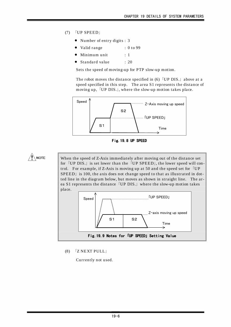
CHAPTER 19 DETAILS OF SYSTEM PARAMETERS
19-6
(7) 「UP SPEED」
• Number of entry digits : 3
• Valid range : 0 to 99
• Minimum unit : 1
• Standard value : 20
Sets the speed of moving-up for PTP slow-up motion.
The robot moves the distance specified in (6) 「UP DIS.」 above at aspeed specified in this step. The area S1 represents the distance ofmoving up, 「UP DIS.」, where the slow-up motion takes place.
Speed
Time
Z-Axis moving up speed
「UP SPEED」
S1
S2
Fig.19.Fig.19.Fig.19.Fig.19.8888 UP SPEED UP SPEED UP SPEED UP SPEED
When the speed of Z-Axis immediately after moving out of the distance setfor 「UP DIS.」 is set lower than the 「UP SPEED」, the lower speed will con-trol. For example, if Z-Axis is moving up at 50 and the speed set for 「UPSPEED」 is 100, the axis does not change speed to that as illustrated in dot-ted line in the diagram below, but moves as shown in straight line. The ar-ea S1 represents the distance 「UP DIS.」 where the slow-up motion takesplace.
Speed
TimeS1 S2
「UP SPEED」
Z-axis moving up speed
Fig.19.Fig.19.Fig.19.Fig.19.9999 Notes for Notes for Notes for Notes for 「「「「UP SPEEDUP SPEEDUP SPEEDUP SPEED」」」」 Setting Value Setting Value Setting Value Setting Value
(8) 「Z NEXT PULL」
Currently not used.
CHAPTER 19 DETAILS OF SYSTEM PARAMETERS
19-7
19.1.219.1.219.1.219.1.2 AXIS SPEEDAXIS SPEEDAXIS SPEEDAXIS SPEED
(1) 「SPEED A, B (X, Y) W」 (Speed of axes, A, B (X, Y) W)
(2) 「SPEED Z」 (Speed of Z-Axis)
• Number of entry digits : 3
• Valid range : 0 to 100
• Minimum unit : 1
• Standard value : 100
For automatic operation, specify the operating speed of each axisexcept for that in CPC operation.
The maximum speed of each axis differs depending on the robottype. The maximum speed is scaled into 100 levels (0: Minimumspeed to 100: Maximum speed). The speed can be specified by se-lecting a value (0-100) which functions as a ratio to the maximumspeed. The value specified in this step sets the speed of every posi-tioning.
The speed in CPC operation should be specified for 「CPC SPEED」described in the following section.
(3) 「SPEED B」 (B-Axis speed for expansion)
(4) 「SPEED W」 (W-Axis speed for expansion)
(5) 「EXPANSION 2」 (R-Axis speed for expansion)
(6) 「EXPANSION 1」 (C-Axis speed for expansion)
• Number of entry digits : 3
• Valid range : 0 to 100
• Minimum unit : 1
• Standard value : 100
Use the above items to specify a speed for each of the axes as ex-panded functions. In this case, 「SPEED A, B (X, Y), W」 functionsas the setting for the speed of A-Axis (X-Axis). For automatic op-eration, specify the operating speed of each axis except for that inCPC operation. The maximum speed of each axis differs depend-ing on the robot type. The maximum speed is scaled into 100 levels(0: Minimum speed to 100: Maximum speed). The speed can bespecified by selecting a value (0-100) which functions as a ratio tothe maximum speed.
CHAPTER 19 DETAILS OF SYSTEM PARAMETERS
19-8
19.1.319.1.319.1.319.1.3 CPC CONSTANTCPC CONSTANTCPC CONSTANTCPC CONSTANT
(1) 「CPC SPEED」
• Number of entry digits : 3
• Valid range : 0 to 999
• Minimum unit : 1
• Standard value : 100
Sets speed for interpolation (CPC operation). The scale unit forthis item is 1 mm/sec.
The tip speed depends on the setting of 「CPC SPEED」 and the F-code specified for the start of the CPC operation.
(mm/sec)(mm/sec)(mm/sec)(mm/sec)Tip speed (mm/sec) = Tip speed (mm/sec) = Tip speed (mm/sec) = Tip speed (mm/sec) = 「「「「CPC SPEEDCPC SPEEDCPC SPEEDCPC SPEED」」」」 x x x x1 + F-code1 + F-code1 + F-code1 + F-code
100100100100
The maximum speed differs depending on the robot type. Even if avalue greater than the maximum speed specific to the robot is set,the robot will operate at its rated maximum speed.
(2) 「CPC F.F. GAIN」
Currently not used.
(3) 「SPLINE SPEED」
Currently not used.
(4) 「CPC CONSTANT」
• Number of entry digits : 3
• Valid range : 0 to 100
• Minimum unit : 1
• Standard value : 0
Sets the smoothness at the passing point in continuous CPC opera-tion. The setting range is between 0-100%. The curve is mostsmooth with the setting 0, and the most steep with the setting 100.
(5) 「CPC ACCEL/DECEL」 (CPC acceleration/deceleration)
• Number of entry digits : 3
• Valid range : 0 to 100
• Minimum unit : 1
• Standard value : 80
Sets the acceleration/deceleration of the speed during CPC opera-tion.
CHAPTER 19 DETAILS OF SYSTEM PARAMETERS
19-9
19.219.219.219.2 RESPONSERESPONSERESPONSERESPONSE
19.2.119.2.119.2.119.2.1 ACCELACCELACCELACCEL
The accelerating/decelerating time is determined by the robot type, and setby configuration. (Refer to 20.4, Assigning Motors to Robot Axes.”) Theaccelerating/decelerating time set in the configuration is treated as theminimum time required. Items in this group set the ratio of (number oftimes of) such time required to complete the acceleration/deceleration.
(1) 「ACCEL SELECT」
• Standard value : AUTO
Currently the above value is not used. The setting is constantlyMANUAL.
Selects either to set acceleration/deceleration with the settings ofthe following (2)「ACCEL A」 to (7)「ACCEL C」, or to set the opti-mized acceleration/deceleration using the weight of work in addi-tion to the settings of (2) to (7). (selecting a character-form value)
AUTO : Automatically creates to set an accelerat-ing/decelerating time.
Optimizes the acceleration/deceleration by using thevalues of (2)「ACCEL A」 to (7)「ACCEL C」 and the set-ting of 「PTP WEIGHT」 reached by selecting「RESPONSE」→「RESPONSE」 in System Parametermenu. Allows smooth acceleration/deceleration forcarrying heavy works.
MANUAL : Requires specifying values for (2)「ACCEL A」 to (7)「ACCEL C」.
AUTO is quite effective for SCARA (horizontal multi-articulated) robots.However, for Cartesian robots, acceleration varies due to the simplified cal-culation value of 「PTP WEIGHT」. Therefore, to obtain a shorter tacttime, change values for the following items of acceleration data with the「PTP WEIGHT」 set to 0.
CHAPTER 19 DETAILS OF SYSTEM PARAMETERS
19-10
(2) 「ACCEL A」
(3) 「ACCEL B」
(4) 「ACCEL Z」
(5) 「ACCEL W」
(6) 「ACCEL R」
(7) 「ACCEL C」
• Number of entry digits : 3
• Valid range : 0 to 100
• Minimum unit : 1
• Standard value : 80
Each of the above is to slow-down acceleration/deceleration of theaxis. In standard condition, always set between 70-100. Thesmaller the value becomes, the more gradual the acceleration be-comes.
Table Table Table Table 19191919....1111 Set Value and Acceleration/Deceleration Time (Minimum Time:1) Set Value and Acceleration/Deceleration Time (Minimum Time:1) Set Value and Acceleration/Deceleration Time (Minimum Time:1) Set Value and Acceleration/Deceleration Time (Minimum Time:1)
「「「「ACCELACCELACCELACCEL」」」」 value value value value Acceleration/Deceleration timeAcceleration/Deceleration timeAcceleration/Deceleration timeAcceleration/Deceleration time
100 1
90 10/9
80 10/8
70 10/7
60 10/6
50 10/5
40 10/4
30 10/3
20 10/2
10 10/1
The optimum values of 「ACCEL」 for various robot with workingload are given below.
Table Table Table Table 19191919....2222 Optimum ACCEL Value and Working load Optimum ACCEL Value and Working load Optimum ACCEL Value and Working load Optimum ACCEL Value and Working load
「「「「ACCELACCELACCELACCEL」」」」 value value value value AR-C270AR-C270AR-C270AR-C270 AR-C350AR-C350AR-C350AR-C350 MBMBMBMB
80With 2kg
working load
With 2kg
working load
With standard
working load
70
60With 4kg
working load
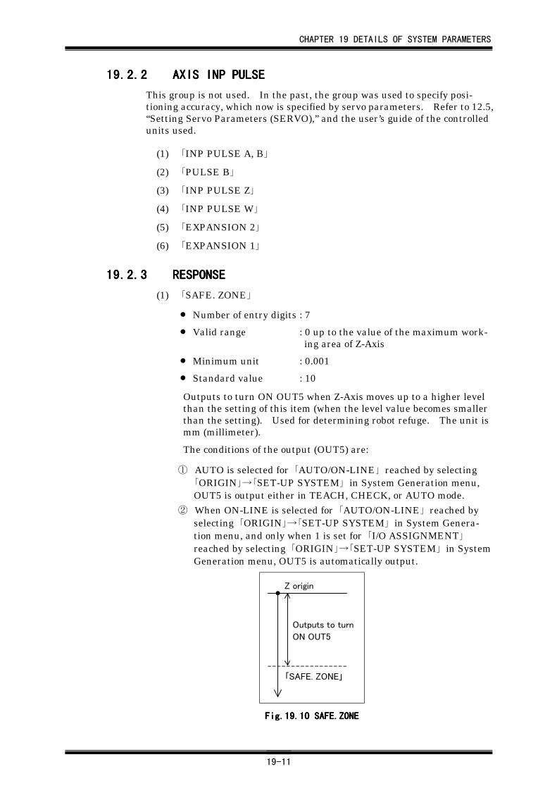
CHAPTER 19 DETAILS OF SYSTEM PARAMETERS
19-11
19.2.219.2.219.2.219.2.2 AXIS INP PULSEAXIS INP PULSEAXIS INP PULSEAXIS INP PULSE
This group is not used. In the past, the group was used to specify posi-tioning accuracy, which now is specified by servo parameters. Refer to 12.5,“Setting Servo Parameters (SERVO),” and the user’s guide of the controlledunits used.
(1) 「INP PULSE A, B」
(2) 「PULSE B」
(3) 「INP PULSE Z」
(4) 「INP PULSE W」
(5) 「EXPANSION 2」
(6) 「EXPANSION 1」
19.2.319.2.319.2.319.2.3 RESPONSERESPONSERESPONSERESPONSE
(1) 「SAFE. ZONE」
• Number of entry digits : 7
• Valid range : 0 up to the value of the maximum work-ing area of Z-Axis
• Minimum unit : 0.001
• Standard value : 10
Outputs to turn ON OUT5 when Z-Axis moves up to a higher levelthan the setting of this item (when the level value becomes smallerthan the setting). Used for determining robot refuge. The unit ismm (millimeter).
The conditions of the output (OUT5) are:
① AUTO is selected for 「AUTO/ON-LINE」 reached by selecting「ORIGIN」→「SET-UP SYSTEM」 in System Generation menu,OUT5 is output either in TEACH, CHECK, or AUTO mode.
② When ON-LINE is selected for 「AUTO/ON-LINE」 reached byselecting 「ORIGIN」→「SET-UP SYSTEM」 in System Genera-tion menu, and only when 1 is set for 「I/O ASSIGNMENT」reached by selecting 「ORIGIN」→「SET-UP SYSTEM」 in SystemGeneration menu, OUT5 is automatically output.
Z origin
「SAFE. ZONE」
Outputs to turn
ON OUT5
Fig.19.Fig.19.Fig.19.Fig.19.10101010 SAFE.ZONE SAFE.ZONE SAFE.ZONE SAFE.ZONE
CHAPTER 19 DETAILS OF SYSTEM PARAMETERS
19-12
・ The setting becomes invalid when A-CAL has not been completed. WithA-CAL incomplete, output of OUT5 is always OFF.
・ In KEY-IN mode, OUT5 will not change.・ When PULL-UP function of Z-Axis is used, specify for 「SAFE. ZONE」 a
value greater than the setting of 「PULL-UP」 i. If the same value as「PULL-UP」 is set for 「SAFE. ZONE」, output of OUT5 may keepswitching ON and OFF or may not turn ON.
(2) 「A-CAL SPEED」
• Number of entry digits : 3
• Valid range : 1 to 999
• Minimum unit : 1
• Standard value : 50
Sets speed during A-CAL.
The maximum speed of each axis varies depending on the robot type.The maximum speed is scaled into 1000 levels (0.1% to 99.9 %), andthe speed can be set between the above range. However, for en-suring safety, the robot will not operate at 250mm/sec or greater.
(3) 「INCHING SPEED」
• Number of entry digits : 3
• Valid range : 1 to 999
• Minimum unit : 1
• Standard value : 2
Sets inching speed.
The maximum speed of each axis varies depending on the robot type.The maximum speed is scaled into 1000 levels (0.1% to 99.9 %), andthe speed can be set between the above range. However, for en-suring safety, the robot will not operate at 250mm/sec or greater.
(4) 「PTP WEIGHT」
• Number of entry digits : 7
• Valid range : 0 up to the value of the maximumtransportation weight
• Minimum unit : 0.001
• Standard value : 2
Specifies the total weight of tip tool and a work (kg). By using thisvalue, the system automatically optimizes the accelera-tion/deceleration during PTP operation and pass PTP operation.The optimization is constantly carried out during pass PTP opera-tion. For PTP operation, acceleration/deceleration is optimizedwhen AUTO is set for 「ACCEL SELECT」 reached by selecting「RESPONSE」→「ACCEL」 in System Generation menu.
i: Specified by the System Parameter, 「MOTION」→「MOTION」→「PULL-UP」.
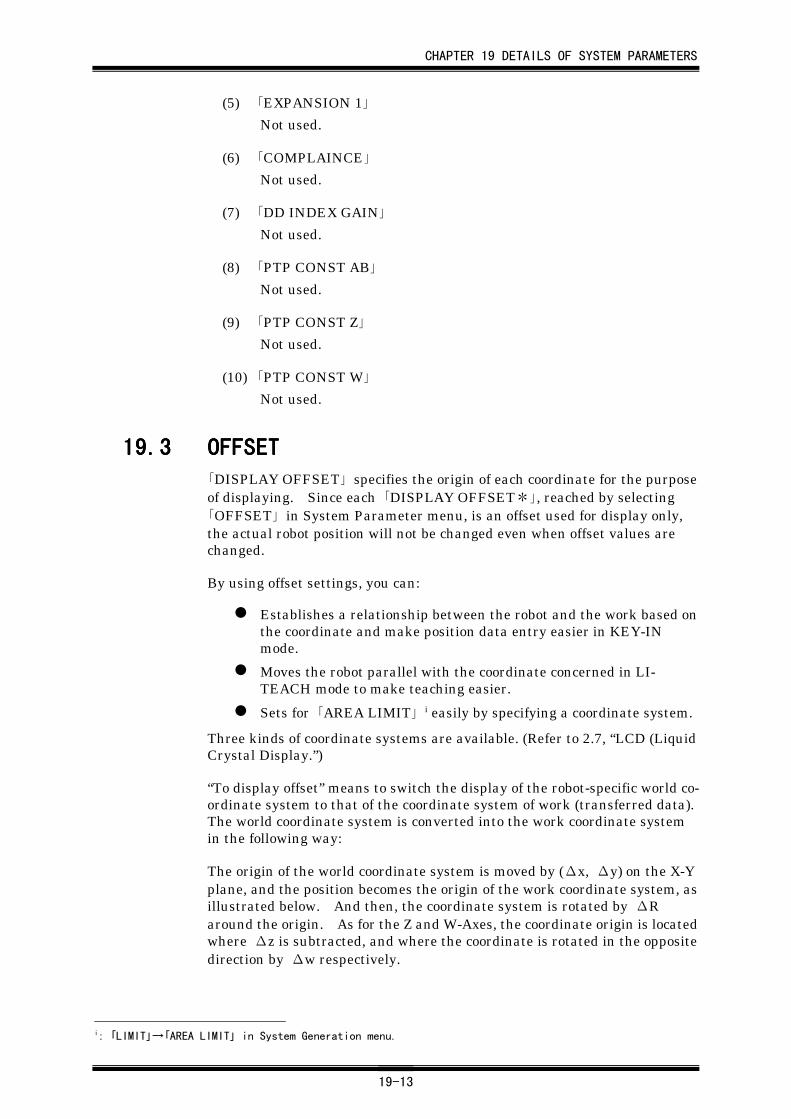
CHAPTER 19 DETAILS OF SYSTEM PARAMETERS
19-13
(5) 「EXPANSION 1」
Not used.
(6) 「COMPLAINCE」
Not used.
(7) 「DD INDEX GAIN」
Not used.
(8) 「PTP CONST AB」
Not used.
(9) 「PTP CONST Z」
Not used.
(10) 「PTP CONST W」
Not used.
19.319.319.319.3 OFFSETOFFSETOFFSETOFFSET「DISPLAY OFFSET」 specifies the origin of each coordinate for the purposeof displaying. Since each 「DISPLAY OFFSET*」, reached by selecting「OFFSET」 in System Parameter menu, is an offset used for display only,the actual robot position will not be changed even when offset values arechanged.
By using offset settings, you can:
Establishes a relationship between the robot and the work based onthe coordinate and make position data entry easier in KEY-INmode.
Moves the robot parallel with the coordinate concerned in LI-TEACH mode to make teaching easier.
Sets for 「AREA LIMIT」 i easily by specifying a coordinate system.
Three kinds of coordinate systems are available. (Refer to 2.7, “LCD (LiquidCrystal Display.”)
“To display offset” means to switch the display of the robot-specific world co-ordinate system to that of the coordinate system of work (transferred data).The world coordinate system is converted into the work coordinate systemin the following way:
The origin of the world coordinate system is moved by (Δx, Δy) on the X-Yplane, and the position becomes the origin of the work coordinate system, asillustrated below. And then, the coordinate system is rotated by ΔRaround the origin. As for the Z and W-Axes, the coordinate origin is locatedwhere Δz is subtracted, and where the coordinate is rotated in the oppositedirection by Δw respectively.
i: 「LIMIT」→「AREA LIMIT」 in System Generation menu.
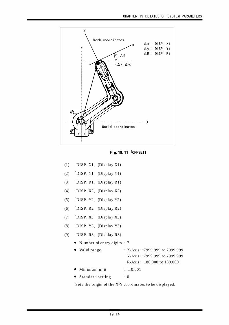
CHAPTER 19 DETAILS OF SYSTEM PARAMETERS
19-14
World coordinates
ΔR
Work coordinates
y
xY
X
(Δx,Δy)
Δx=「DISP. X」
Δy=「DISP. Y」
ΔR=「DISP. R」
Fig.19.Fig.19.Fig.19.Fig.19.11111111 「「「「OFFSETOFFSETOFFSETOFFSET」」」」
(1) 「DISP. X1」 (Display X1)
(2) 「DISP. Y1」 (Display Y1)
(3) 「DISP. R1」 (Display R1)
(4) 「DISP. X2」 (Display X2)
(5) 「DISP. Y2」 (Display Y2)
(6) 「DISP. R2」 (Display R2)
(7) 「DISP. X3」 (Display X3)
(8) 「DISP. Y3」 (Display Y3)
(9) 「DISP. R3」 (Display R3)
• Number of entry digits : 7
• Valid range : X-Axis: -7999.999 to 7999.999Y-Axis: -7999.999 to 7999.999R-Axis: -180.000 to 180.000
• Minimum unit : ±0.001
• Standard setting : 0
Sets the origin of the X-Y coordinates to be displayed.
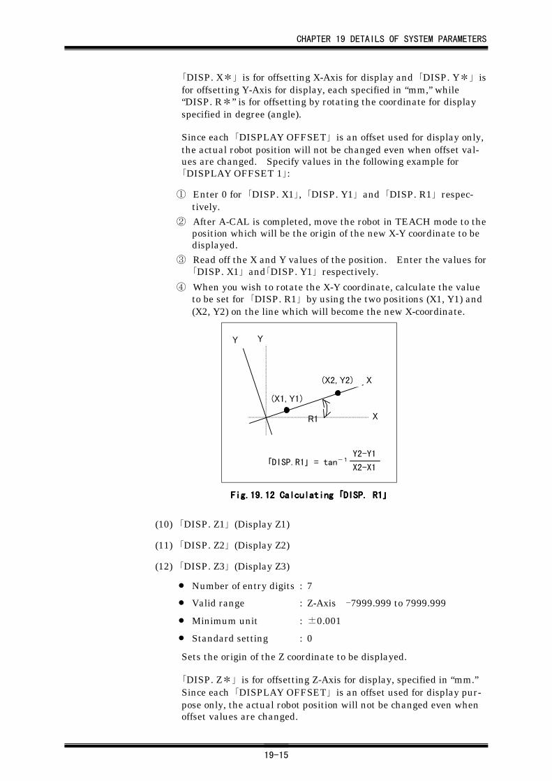
CHAPTER 19 DETAILS OF SYSTEM PARAMETERS
19-15
「DISP. X*」 is for offsetting X-Axis for display and 「DISP. Y*」 isfor offsetting Y-Axis for display, each specified in “mm,” while“DISP. R*” is for offsetting by rotating the coordinate for displayspecified in degree (angle).
Since each 「DISPLAY OFFSET」 is an offset used for display only,the actual robot position will not be changed even when offset val-ues are changed. Specify values in the following example for「DISPLAY OFFSET 1」:
① Enter 0 for 「DISP. X1」, 「DISP. Y1」 and 「DISP. R1」 respec-tively.
② After A-CAL is completed, move the robot in TEACH mode to theposition which will be the origin of the new X-Y coordinate to bedisplayed.
③ Read off the X and Y values of the position. Enter the values for「DISP. X1」 and「DISP. Y1」 respectively.
④ When you wish to rotate the X-Y coordinate, calculate the valueto be set for 「DISP. R1」 by using the two positions (X1, Y1) and(X2, Y2) on the line which will become the new X-coordinate.
「DISP.R1」 = tan-1Y2-Y1
X2-X1
(X2, Y2)
(X1, Y1)
R1
Y Y
X
X
Fig.19.Fig.19.Fig.19.Fig.19.12121212 Calculating Calculating Calculating Calculating 「「「「DISP. R1DISP. R1DISP. R1DISP. R1」」」」
(10) 「DISP. Z1」 (Display Z1)
(11) 「DISP. Z2」 (Display Z2)
(12) 「DISP. Z3」 (Display Z3)
• Number of entry digits : 7
• Valid range : Z-Axis -7999.999 to 7999.999
• Minimum unit : ±0.001
• Standard setting : 0
Sets the origin of the Z coordinate to be displayed.
「DISP. Z*」 is for offsetting Z-Axis for display, specified in “mm.”Since each 「DISPLAY OFFSET」 is an offset used for display pur-pose only, the actual robot position will not be changed even whenoffset values are changed.
CHAPTER 19 DETAILS OF SYSTEM PARAMETERS
19-16
(13) 「DISP. W1」 (Display W1)
(14) 「DISP. W2」 (Display W2))
(15) 「DISP. W3」 (Display W3)
• Number of entry digits : 7
• Valid range : W-Axis -540.000 to 540.000
• Minimum unit : ±0.001
• Standard setting : 0
Offset value of W-Axis from X-Y coordinate.
A value for W-Axis is an angle displayed based on the X-Y coordi-nates. After an X-Y coordinate system is specified by display off-setting, the operating direction of the W-Axis and the display will beconstant on the X-Y coordinate system.
「DISP. W*」 is for setting the origin on W-Axis for the setting co-ordinate. Since each 「DISPLAY OFFSET」 is an offset used fordisplay purpose only, the actual robot position will not be changedeven when offset values are changed.
Specify values in the following example for 「DISPLAY OFFSET 1」:
① Enter system data for 「DISP. X1」, 「DISP. Y1」 and 「DISP. R1」respectively to specify the X-Y coordinate system.
② Enter 0 for 「DISP. W1」.
③ After A-CAL is completed, rotate the robot in TEACH mode tothe position where the origin of the new coordinate will be set.
④ Read off the W1 value of the position. Enter the value for「DISP. W1」.
Since 「DISP. W1」 is an offset value for the display purpose only, themechanical working area will not be changed. Because of this, if the workcoordinate system is newly changed, entering data of W-Axis may not be ac-cepted even though the values are identical with those of the former coordi-nate system, “AREA ERROR” being caused.
(16) 「TOOL X1」
(17) 「TOOL Y1」
(18) 「TOOL Z1」
(19) 「TOOL X2」
(20) 「TOOL Y2」
(21) 「TOOL Z2」
(22) 「TOOL X3」
(23) 「TOOL Y3」
CHAPTER 19 DETAILS OF SYSTEM PARAMETERS
19-17
(24) 「TOOL Z3」
Currently not supported.
Specify data to switch display referenced with a coordinate systemwith the origin at the tool’s working center.
Three types are available, allowing three different displays for thethree tools. These items are used in combination with the 「DISP.**」 items described before.
19.419.419.419.4 SET-UPSET-UPSET-UPSET-UP「SET-UP」 contains data areas for expansion. There are two groups,「EXPANSION A」 and 「EXPANSION B」.
19.4.119.4.119.4.119.4.1 EXPANSION AEXPANSION AEXPANSION AEXPANSION A
Used for expansion.
(1) 「Pass PTP Select」
Currently not supported.
Switches from pass PTP operation, in which the robot does not stopat the passing position, to continuous pass PTP operation, in whichregular PTP operation is continued without communication withexternal units when M-data values in the thirties (30-39) are used.
Values 0 : Specifies pass PTP operation where robot does notstop at the passing position.
1 : Enables continuous PTP operation without com-munication with external devices. Stops the robottemporarily at the passing position.
(2) 「Base Pos Addr1」 (Base Position Address 1)
(3) 「Base Pos Addr2」 (Base Position Address 2)
(4) 「Base Pos Addr3」 (Base Position Address 3)
(5) 「Base Pos Addr4」 (Base Position Address 4)
• Number of entry digits : 3
• Valid range : 0 to the value specified for 「ADDRESSMAX」 i
• Minimum unit : 1
• Standard setting : 0
Specifies the address for the reference base position of the robot(Robot origin).
i: 「LIMIT」→「ADDRESS MAX」→「ADRRESS MAX」 in System Generation menu.
CHAPTER 19 DETAILS OF SYSTEM PARAMETERS
19-18
With 「I/O ASSIGNMENT」 set to 4, by selecting 「ORIGIN」→「SET-UP SYSTEM」→「I/O ASSIGNMENT」 in System Generationmenu, and when the robot is positioned at one of the addressesspecified for the items above, OUT4 is output. You can specify fourpoints. OUT4 turns ON when the robot positions at one of the fourpoints specified.
By using this output, interlock system can be established to givepermission of start to the externally controlled units. To give someallowance in stopping position, set a value for the next item 「BasePos Pulse」.
(6) 「Base Pos Pulse」 (Base Position Pulse)
• Number of entry digits : 5
• Valid range : 0 to 99999
• Minimum unit : 1
• Standard setting : 0
Specifies the allowable variation range(±number of pulses), whereOUT4 turns ON, for the address specified for 「Base Pos Addr」above. Specify a value that is a number of pulses.
(7) 「Safety select」
Specifies reference base position for 「ARCH UP」 i and 「SAFE.ZONE」 ii settings. Currently the setting for this item is fixed to 0.
Values 0 : Specifies the origin of Z-Axis as the reference posi-tion, validating absolute values of 「ARCH UP」 and「SAFE. ZONE」.
1 : Specifies the position currently located as the refer-ence, turning OUT5 signal (ZONE output) ON whenZ-Axis rises by a value specified for 「SAFE.ZONE」.
2 : Specifies the position currently located as the refer-ence, starting to move A and B-Axes (X and Y-Axes)when Z-Axis rises by a value specified for 「ARCHUP」.
19.4.219.4.219.4.219.4.2 EXPANSION BEXPANSION BEXPANSION BEXPANSION B
(1) 「SENS. OFF」 (Sensor Offset)
Currently not supported. Specifies an offset upon stop of W-Axissensor.
(2) 「SENS. SKIP」 (Sensor Skip)
Currently not supported. Specifies an area where W-Axis sensor isignored upon stop of W-Axis sensor.
i : 「MOTION」→「MOTION」→「ARCH UP」 in System Parameter menuii : 「RESPONSE」→「RESPONSE」→「SAFE.ZONE」 in System Parameter menu
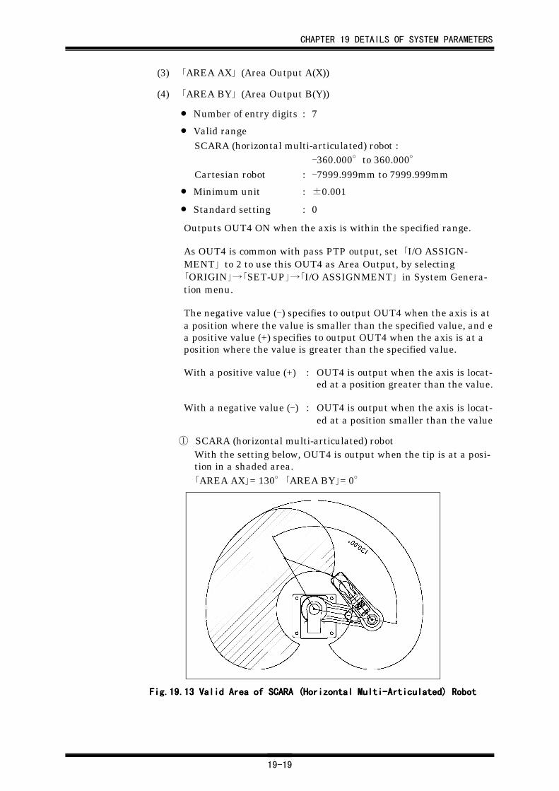
CHAPTER 19 DETAILS OF SYSTEM PARAMETERS
19-19
(3) 「AREA AX」 (Area Output A(X))
(4) 「AREA BY」 (Area Output B(Y))
• Number of entry digits : 7
• Valid rangeSCARA (horizontal multi-articulated) robot :
-360.000°to 360.000°Cartesian robot : -7999.999mm to 7999.999mm
• Minimum unit : ±0.001
• Standard setting : 0
Outputs OUT4 ON when the axis is within the specified range.
As OUT4 is common with pass PTP output, set 「I/O ASSIGN-MENT」 to 2 to use this OUT4 as Area Output, by selecting「ORIGIN」→「SET-UP」→「I/O ASSIGNMENT」 in System Genera-tion menu.
The negative value (-) specifies to output OUT4 when the axis is ata position where the value is smaller than the specified value, and ea positive value (+) specifies to output OUT4 when the axis is at aposition where the value is greater than the specified value.
With a positive value (+) : OUT4 is output when the axis is locat-ed at a position greater than the value.
With a negative value (-) : OUT4 is output when the axis is locat-ed at a position smaller than the value
① SCARA (horizontal multi-articulated) robotWith the setting below, OUT4 is output when the tip is at a posi-tion in a shaded area.「AREA AX」= 130°「AREA BY」= 0°
Fig.19.Fig.19.Fig.19.Fig.19.13131313 Valid Area of SCARA (Horizontal Multi-Articulated) Robot Valid Area of SCARA (Horizontal Multi-Articulated) Robot Valid Area of SCARA (Horizontal Multi-Articulated) Robot Valid Area of SCARA (Horizontal Multi-Articulated) Robot
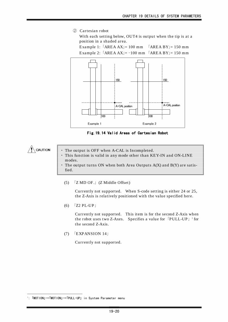
CHAPTER 19 DETAILS OF SYSTEM PARAMETERS
19-20
② Cartesian robotWith each setting below, OUT4 is output when the tip is at aposition in a shaded area.Example 1: 「AREA AX」= 100 mm 「AREA BY」= 150 mmExample 2: 「AREA AX」= -100 mm 「AREA BY」= 150 mm
A-CAL position
100
150
A-CAL position
100
150
Example 1 Example 2
Fig.19.Fig.19.Fig.19.Fig.19.14141414 Valid Areas of Cartesian Robot Valid Areas of Cartesian Robot Valid Areas of Cartesian Robot Valid Areas of Cartesian Robot
・ The output is OFF when A-CAL is Incompleted.・ This function is valid in any mode other than KEY-IN and ON-LINE
modes.・ The output turns ON when both Area Outputs A(X) and B(Y) are satis-
fied.
(5) 「Z MD OF.」 (Z Middle Offset)
Currently not supported. When S-code setting is either 24 or 25,the Z-Axis is relatively positioned with the value specified here.
(6) 「Z2 PL-UP」
Currently not supported. This item is for the second Z-Axis whenthe robot uses two Z-Axes. Specifies a value for 「PULL-UP」 i forthe second Z-Axis.
(7) 「EXPANSION 14」
Currently not supported.
i: 「MOTION」→「MOTION」→「PULL-UP」 in System Parameter menu
CHAPTER 19 DETAILS OF SYSTEM PARAMETERS
19-21
19.519.519.519.5 REMOTEREMOTEREMOTEREMOTEThe groups in REMOTE display data set by S command (SAVE) of theHRCS-RⅣ i . You cannot enter data for items in these groups.
Data that can be displayed are those in 「MOTION」 and 「RESPONSE」groups. For details, refer to each group.
19.5.119.5.119.5.119.5.1 MOTIONMOTIONMOTIONMOTION
(1) 「PULL-UP」
(2) 「ARCH UP」
(3) 「ARCH DOWN」
(4) 「INS DIS. 」
(5) 「INS SPEED」
(6) 「UP DIS. 」
(7) 「UP SPEED」
19.5.219.5.219.5.219.5.2 SPEED/ACCEL/INPOSSPEED/ACCEL/INPOSSPEED/ACCEL/INPOSSPEED/ACCEL/INPOS
(1) 「SPEED A,B(X,Y)W」
(2) 「SPEED B」
(3) 「SPEED Z」
(4) 「SPEED W」
(5) 「EXPANSION 1」
(6) 「EXPANSION 2」
(7) 「ACCEL A,B(X,Y)W」
(8) 「ACCEL ABW(PASS)」
(9) 「ACCEL Z」
(10) 「ACCEL Z(PASS)」
(11) 「EXPANSION 3」
(12) 「EXPANSION 4」
(13) 「INP PULSE A,B」
(14) 「INP PULSE B」
(15) 「INP PULSE Z」
(16) 「INP PULSE W」
(17) 「EXPANSION 5」
(18) 「EXPANSION 6」
i : HRCS-RⅣ: Communication protocol of our company. Used to control robot with RS-232C from the higher
computer (PC, or the like). For details, refer to separate volume, "HRCS-RⅣ Operation Manual."
CHAPTER 19 DETAILS OF SYSTEM PARAMETERS
19-22
19.5.319.5.319.5.319.5.3 REMOTE MOTIONREMOTE MOTIONREMOTE MOTIONREMOTE MOTION
(1) 「CPC SPEED」
(2) 「CPC F.F.GAIN」
(3) 「SPLINE SPEED」
(4) 「A-CAL SPEED」
(5) 「INCHING SPEED」
(6) 「EXPANSION 1」
(7) 「PTP WEIGHT」
(8) 「EXPANSION 2」
(9) 「LOCAL COORDINATE」
(10) 「W AXIS ACCEL」
(11) 「W AXIS DECEL」
(12) 「OPTION DATA 1」
(13) 「OPTION DATA 2」
(14) 「OPTION DATA 3」
(15) 「EXPANSION 3」
(16) 「EXPANSION 4」
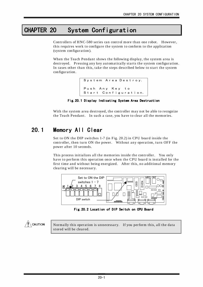
CHAPTER 20 SYSTEM CONFIGURATION
20-1
CHAPTER 20CHAPTER 20CHAPTER 20CHAPTER 20 System ConfigurationSystem ConfigurationSystem ConfigurationSystem Configuration
Controllers of HNC-580 series can control more than one robot. However,this requires work to configure the system to conform to the application(system configuration).
When the Teach Pendant shows the following display, the system area isdestroyed. Pressing any key automatically starts the system configuration.In cases other than this, take the steps described below to start the systemconfiguration.
System Area Destroy.
Push Any Key to
Start Configuration.
Fig.20.Fig.20.Fig.20.Fig.20.1111 Display Indicating System Area Destruction Display Indicating System Area Destruction Display Indicating System Area Destruction Display Indicating System Area Destruction
With the system area destroyed, the controller may not be able to recognizethe Teach Pendant. In such a case, you have to clear all the memories.
20.120.120.120.1 Memory All ClearMemory All ClearMemory All ClearMemory All ClearSet to ON the DIP switches 1-7 (in Fig. 20.2) in CPU board inside thecontroller, then turn ON the power. Without any operation, turn OFF thepower after 10 seconds.
This process initializes all the memories inside the controller. You onlyhave to perform this operation once when the CPU board is installed for thefirst time and without being energized. After this, no additional memoryclearing will be necessary.
DIP switch
NO
→
Set to ON the DIP
switches 1 - 7
OD
D
HPC-767
EV
EN
2 3 4 5 6 7 81
Fig.20.Fig.20.Fig.20.Fig.20.2222 Location of DIP Switch on CPU Board Location of DIP Switch on CPU Board Location of DIP Switch on CPU Board Location of DIP Switch on CPU Board
Normally this operation is unnecessary. If you perform this, all the datastored will be cleared.
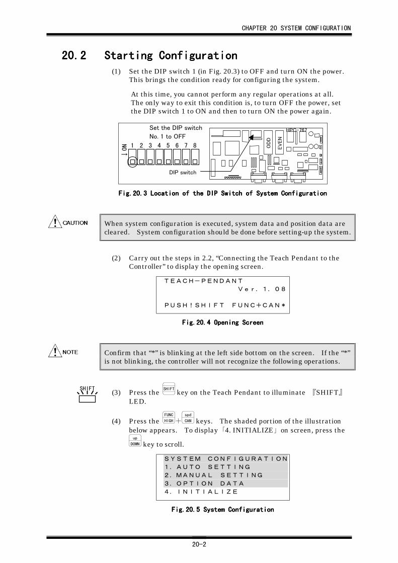
CHAPTER 20 SYSTEM CONFIGURATION
20-2
20.220.220.220.2 Starting ConfigurationStarting ConfigurationStarting ConfigurationStarting Configuration(1) Set the DIP switch 1 (in Fig. 20.3) to OFF and turn ON the power.
This brings the condition ready for configuring the system.
At this time, you cannot perform any regular operations at all.The only way to exit this condition is, to turn OFF the power, setthe DIP switch 1 to ON and then to turn ON the power again.
DIP switch
2 3 4 5 6 7 81
NO
→
Set the DIP switch
No. 1 to OFF
OD
D
HPC-767
EV
EN
Fig.20.Fig.20.Fig.20.Fig.20.3333 Location of the DIP Switch of System Configuration Location of the DIP Switch of System Configuration Location of the DIP Switch of System Configuration Location of the DIP Switch of System Configuration
When system configuration is executed, system data and position data arecleared. System configuration should be done before setting-up the system.
(2) Carry out the steps in 2.2, “Connecting the Teach Pendant to theController” to display the opening screen.
TEACH-PENDANT
Ver.1.08
PUSH!SHIFT FUNC+CAN*
Fig.20.Fig.20.Fig.20.Fig.20.4444 Opening Screen Opening Screen Opening Screen Opening Screen
Confirm that “*” is blinking at the left side bottom on the screen. If the “*”is not blinking, the controller will not recognize the following operations.
(3) Press the SHIFT
key on the Teach Pendant to illuminate 『SHIFT』LED.
(4) Press the FUNC
HIGH+spd
CAN keys. The shaded portion of the illustrationbelow appears. To display 「4. INITIALIZE」 on screen, press theup
DOWN key to scroll.
SYSTEM CONFIGURATION
1.AUTO SETTING
2.MANUAL SETTING
3.OPTION DATA
4.INITIALIZE
Fig.20.Fig.20.Fig.20.Fig.20.5555 System Configuration System Configuration System Configuration System Configuration
SHIFT
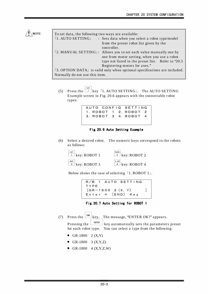
CHAPTER 20 SYSTEM CONFIGURATION
20-3
To set data, the following two ways are available:「1. AUTO SETTING」 : Sets data when you select a robot type/model
from the preset robot list given by thecontroller.
「2. MANUAL SETTING」 : Allows you to set each value manually one byone from motor setting, when you use a robottype not listed in the preset list. Refer to “20.3Registering motors for axes.”
「3. OPTION DATA」 is valid only when optional specifications are included.Normally do not use this item.
(5) Press the cal
1 key 「1. AUTO SETTING」. The AUTO SETTINGExample screen in Fig. 20.6 appears with the connectable robottypes.
AUTO CONFIG SETTING
1.ROBOT 1 2.ROBOT 2
3.ROBOT 3 4.ROBOT 4
Fig.20.Fig.20.Fig.20.Fig.20.6666 Auto Setting Example Auto Setting Example Auto Setting Example Auto Setting Example
(6) Select a desired robot. The numeric keys correspond to the robotsas follows:
cal
1 key: ROBOT 1task
2 key: ROBOT 2mot
3 key: ROBOT 3s.ed
4 key: ROBOT 4
Below shows the case of selecting 「1. ROBOT 1」.
R/B 1 AUTO SETTING
TYPE
[GR-1800 2(X,Y) ]
Enter = [END] Key
Fig.20.Fig.20.Fig.20.Fig.20.7777 Auto Setting for ROBOT 1 Auto Setting for ROBOT 1 Auto Setting for ROBOT 1 Auto Setting for ROBOT 1
(7) Press the END key. The message, “ENTER OK?” appears.
Pressing the ENTER key automatically sets the parameters presetfor each robot type. You can select a type from the following:
• GR-1800 2 (X,Y)
• GR-1800 3 (X,Y,Z)
• GR-1800 4 (X,Y,Z,W)
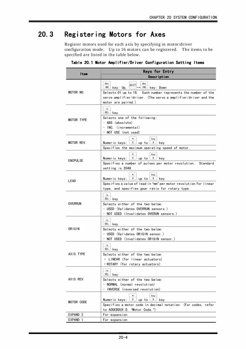
CHAPTER 20 SYSTEM CONFIGURATION
20-4
20.320.320.320.3 Registering Motors for AxesRegistering Motors for AxesRegistering Motors for AxesRegistering Motors for AxesRegister motors used for each axis by specifying in motor/driverconfiguration mode. Up to 16 motors can be registered. The items to bespecified are listed in the table below.
Table 20.Table 20.Table 20.Table 20.1111 Motor Amplifier/Driver Configuration Setting Items Motor Amplifier/Driver Configuration Setting Items Motor Amplifier/Driver Configuration Setting Items Motor Amplifier/Driver Configuration Setting Items
Keys for EntryKeys for EntryKeys for EntryKeys for EntryItemItemItemItem
DescriptionDescriptionDescriptionDescription
dec
INC key: Up, SHIFT→
dec
INC key: Down
MOTOR NO. Selects 01 up to 16. Each number represents the number of the
servo amplifier/driver. (The servo a amplifier/driver and the
motor are paired.)
io
SEL key
MOTOR TYPESelects one of the following:
・ ABS (absolute)
・ INC. (incremental)
・ NOT USE (not used)
Numeric keys: *
0 up to key
9 keyMOTOR REV.
Specifies the maximum operating speed of motor.
Numeric keys: *
0 up to key
9 keyENCPULSE
Specifies a number of pulses per motor revolution. Standard
setting is 2048.
Numeric keys: *
0 up to key
9 keyLEAD
Specifies a value of lead in “mm” per motor revolution for lineartype, and specifies gear ratio for rotary type.
io
SEL key
OVERRUN Selects either of the two below:
・ USED (Validates OVERRUN sensors.)
・ NOT USED (Invalidates OVERUN sensors.)
io
SEL key
ORIGIN Selects either of the two below:
・ USED (Validates ORIGIN sensor.)
・ NOT USED (Invalidates ORIGIN sensor.)
io
SEL key
AXIS TYPE Selects either of the two below:
・ LINEAR (for linear actuators)
・ROTARY (for rotary actuators)
io
SEL key
AXIS REV. Selects either of the two below:
・ NORMAL (normal revolution)
・ INVERSE (reversed revolution)
Numeric keys: *
0 up to key
9 keyMOTOR CODE
Specifies a motor code in decimal notation. (For codes, refer
to AOOEBDUX D, “Motor Code.”)EXPAND 2 For expansion
EXPAND 1 For expansion
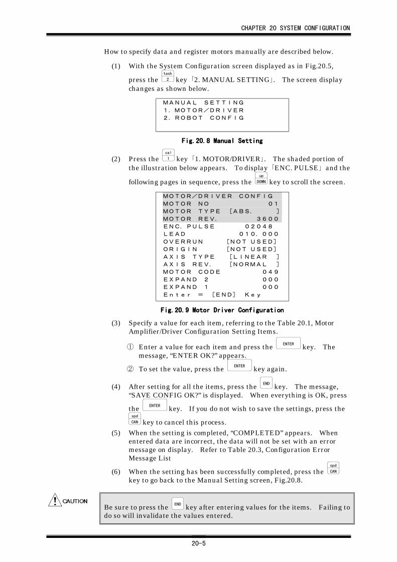
CHAPTER 20 SYSTEM CONFIGURATION
20-5
How to specify data and register motors manually are described below.
(1) With the System Configuration screen displayed as in Fig.20.5,
press the task
2 key 「2. MANUAL SETTING」. The screen displaychanges as shown below.
MANUAL SETTING
1.MOTOR/DRIVER
2.ROBOT CONFIG
Fig.20.Fig.20.Fig.20.Fig.20.8888 Manual Setting Manual Setting Manual Setting Manual Setting
(2) Press the cal
1 key 「1. MOTOR/DRIVER」. The shaded portion ofthe illustration below appears. To display 「ENC. PULSE」 and the
following pages in sequence, press the up
DOWN key to scroll the screen.
MOTOR/DRIVER CONFIG
MOTOR NO 01
MOTOR TYPE [ABS. ]
MOTOR REV. 3600
ENC.PULSE 02048
LEAD 010.000
OVERRUN [NOT USED]
ORIGIN [NOT USED]
AXIS TYPE [LINEAR ]
AXIS REV. [NORMAL ]
MOTOR CODE 049
EXPAND 2 000
EXPAND 1 000
Enter = [END] Key
Fig.20.Fig.20.Fig.20.Fig.20.9999 Motor Driver Configuration Motor Driver Configuration Motor Driver Configuration Motor Driver Configuration
(3) Specify a value for each item, referring to the Table 20.1, MotorAmplifier/Driver Configuration Setting Items.
① Enter a value for each item and press the ENTER key. Themessage, “ENTER OK?” appears.
② To set the value, press the ENTER key again.
(4) After setting for all the items, press the END key. The message,“SAVE CONFIG OK?” is displayed. When everything is OK, press
the ENTER key. If you do not wish to save the settings, press thespd
CAN key to cancel this process.(5) When the setting is completed, “COMPLETED” appears. When
entered data are incorrect, the data will not be set with an errormessage on display. Refer to Table 20.3, Configuration ErrorMessage List
(6) When the setting has been successfully completed, press the spd
CAN
key to go back to the Manual Setting screen, Fig.20.8.
Be sure to press the END key after entering values for the items. Failing todo so will invalidate the values entered.
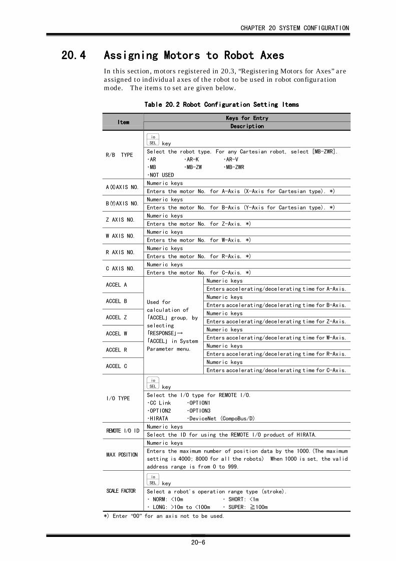
CHAPTER 20 SYSTEM CONFIGURATION
20-6
20.420.420.420.4 Assigning Motors to Robot AxesAssigning Motors to Robot AxesAssigning Motors to Robot AxesAssigning Motors to Robot AxesIn this section, motors registered in 20.3, “Registering Motors for Axes” areassigned to individual axes of the robot to be used in robot configurationmode. The items to set are given below.
Table 20.Table 20.Table 20.Table 20.2222 Robot Configuration Setting Items Robot Configuration Setting Items Robot Configuration Setting Items Robot Configuration Setting Items
Keys for EntryKeys for EntryKeys for EntryKeys for EntryItemItemItemItem
DescriptionDescriptionDescriptionDescription
io
SEL key
R/B TYPESelect the robot type. For any Cartesian robot, select [MB-ZWR].
・AR ・AR-K ・AR-V
・MB ・MB-ZW ・MB-ZWR
・NOT USED
Numeric keysA(X)AXIS NO.
Enters the motor No. for A-Axis (X-Axis for Cartesian type). *)
Numeric keysB(Y)AXIS NO.
Enters the motor No. for B-Axis (Y-Axis for Cartesian type). *)
Numeric keysZ AXIS NO.
Enters the motor No. for Z-Axis. *)
Numeric keysW AXIS NO.
Enters the motor No. for W-Axis. *)
Numeric keysR AXIS NO.
Enters the motor No. for R-Axis. *)
Numeric keysC AXIS NO.
Enters the motor No. for C-Axis. *)
Numeric keysACCEL A
Enters accelerating/decelerating time for A-Axis.
Numeric keysACCEL B
Enters accelerating/decelerating time for B-Axis.
Numeric keysACCEL Z
Enters accelerating/decelerating time for Z-Axis.
Numeric keysACCEL W
Enters accelerating/decelerating time for W-Axis.
Numeric keysACCEL R
Enters accelerating/decelerating time for R-Axis.
Numeric keysACCEL C
Used for
calculation of
「ACCEL」 group, by
selecting
「RESPONSE」→
「ACCEL」 in System
Parameter menu.
Enters accelerating/decelerating time for C-Axis.
io
SEL key
I/O TYPESelect the I/O type for REMOTE I/O.
・CC Link ・OPTION1
・OPTION2 ・OPTION3
・HIRATA ・DeviceNet (CompoBus/D)
Numeric keysREMOTE I/O ID
Select the ID for using the REMOTE I/O product of HIRATA.
Numeric keys
MAX POSITIONEnters the maximum number of position data by the 1000.(The maximum
setting is 4000; 8000 for all the robots) When 1000 is set, the valid
address range is from 0 to 999.
io
SEL key
SCALE FACTOR Select a robot's operation range type (stroke).
・ NORM: <10m ・ SHORT: <1m
・ LONG: >10m to <100m ・ SUPER: ≧100m
*) Enter “00” for an axis not to be used.
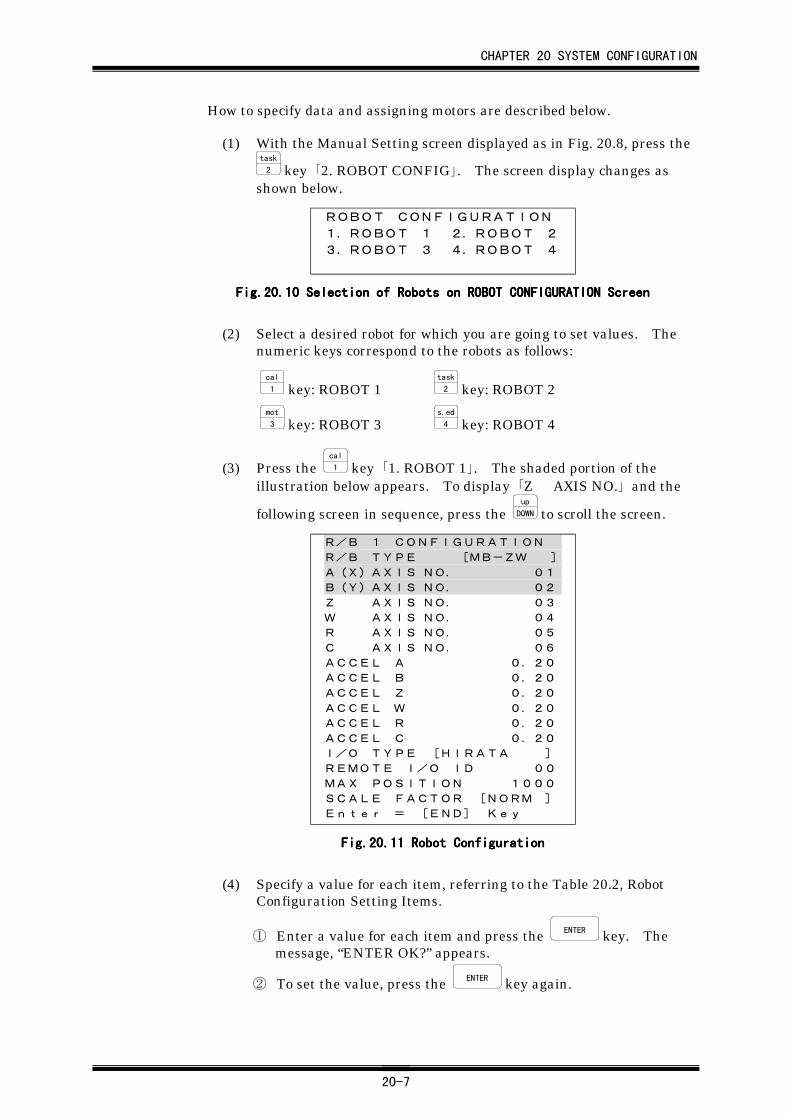
CHAPTER 20 SYSTEM CONFIGURATION
20-7
How to specify data and assigning motors are described below.
(1) With the Manual Setting screen displayed as in Fig. 20.8, press thetask
2 key 「2. ROBOT CONFIG」. The screen display changes asshown below.
ROBOT CONFIGURATION
1.ROBOT 1 2.ROBOT 2
3.ROBOT 3 4.ROBOT 4
Fig.20.Fig.20.Fig.20.Fig.20.10101010 Selection of Robots on ROBOT CONFIGURATION Screen Selection of Robots on ROBOT CONFIGURATION Screen Selection of Robots on ROBOT CONFIGURATION Screen Selection of Robots on ROBOT CONFIGURATION Screen
(2) Select a desired robot for which you are going to set values. Thenumeric keys correspond to the robots as follows:
cal
1 key: ROBOT 1task
2 key: ROBOT 2mot
3 key: ROBOT 3s.ed
4 key: ROBOT 4
(3) Press the cal
1 key 「1. ROBOT 1」. The shaded portion of theillustration below appears. To display 「Z AXIS NO.」 and the
following screen in sequence, press the up
DOWN to scroll the screen.
R/B 1 CONFIGURATION
R/B TYPE [MB-ZW ]
A(X)AXIS NO. 01
B(Y)AXIS NO. 02
Z AXIS NO. 03
W AXIS NO. 04
R AXIS NO. 05
C AXIS NO. 06
ACCEL A 0.20
ACCEL B 0.20
ACCEL Z 0.20
ACCEL W 0.20
ACCEL R 0.20
ACCEL C 0.20
I/O TYPE [HIRATA ]
REMOTE I/O ID 00
MAX POSITION 1000
SCALE FACTOR [NORM ]
Enter = [END] Key
Fig.20.Fig.20.Fig.20.Fig.20.11111111 Robot Configuration Robot Configuration Robot Configuration Robot Configuration
(4) Specify a value for each item, referring to the Table 20.2, RobotConfiguration Setting Items.
① Enter a value for each item and press the ENTER key. Themessage, “ENTER OK?” appears.
② To set the value, press the ENTER key again.
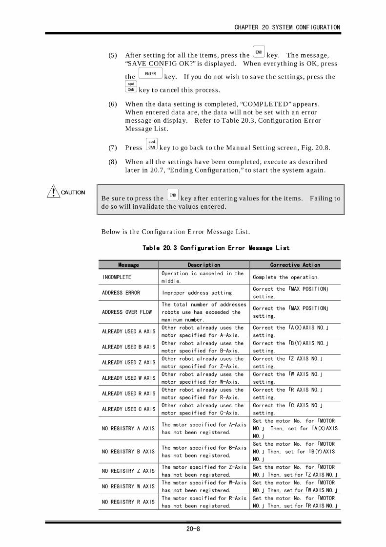
CHAPTER 20 SYSTEM CONFIGURATION
20-8
(5) After setting for all the items, press the END key. The message,“SAVE CONFIG OK?” is displayed. When everything is OK, press
the ENTER key. If you do not wish to save the settings, press thespd
CAN key to cancel this process.
(6) When the data setting is completed, “COMPLETED” appears.When entered data are, the data will not be set with an errormessage on display. Refer to Table 20.3, Configuration ErrorMessage List.
(7) Press spd
CAN key to go back to the Manual Setting screen, Fig. 20.8.
(8) When all the settings have been completed, execute as describedlater in 20.7, “Ending Configuration,” to start the system again.
Be sure to press the END key after entering values for the items. Failing todo so will invalidate the values entered.
Below is the Configuration Error Message List.
Table 20.Table 20.Table 20.Table 20.3333 Configuration Error Message List Configuration Error Message List Configuration Error Message List Configuration Error Message List
MessageMessageMessageMessage DescriptionDescriptionDescriptionDescription Corrective ActionCorrective ActionCorrective ActionCorrective Action
INCOMPLETEOperation is canceled in the
middle.Complete the operation.
ADDRESS ERROR Improper address settingCorrect the 「MAX POSITION」
setting.
ADDRESS OVER FLOW
The total number of addresses
robots use has exceeded the
maximum number.
Correct the 「MAX POSITION」
setting.
ALREADY USED A AXISOther robot already uses the
motor specified for A-Axis.
Correct the 「A(X)AXIS NO.」
setting.
ALREADY USED B AXISOther robot already uses the
motor specified for B-Axis.
Correct the 「B(Y)AXIS NO.」
setting.
ALREADY USED Z AXISOther robot already uses the
motor specified for Z-Axis.
Correct the 「Z AXIS NO.」
setting.
ALREADY USED W AXISOther robot already uses the
motor specified for W-Axis.
Correct the 「W AXIS NO.」
setting.
ALREADY USED R AXISOther robot already uses the
motor specified for R-Axis.
Correct the 「R AXIS NO.」
setting.
ALREADY USED C AXISOther robot already uses the
motor specified for C-Axis.
Correct the 「C AXIS NO.」
setting.
NO REGISTRY A AXISThe motor specified for A-Axis
has not been registered.
Set the motor No. for 「MOTOR
NO.」 Then, set for 「A(X)AXIS
NO.」
NO REGISTRY B AXISThe motor specified for B-Axis
has not been registered.
Set the motor No. for 「MOTOR
NO.」 Then, set for 「B(Y)AXIS
NO.」
NO REGISTRY Z AXISThe motor specified for Z-Axis
has not been registered.
Set the motor No. for 「MOTOR
NO.」 Then, set for 「Z AXIS NO.」
NO REGISTRY W AXISThe motor specified for W-Axis
has not been registered.
Set the motor No. for 「MOTOR
NO.」 Then, set for 「W AXIS NO.」
NO REGISTRY R AXISThe motor specified for R-Axis
has not been registered.
Set the motor No. for 「MOTOR
NO.」 Then, set for 「R AXIS NO.」
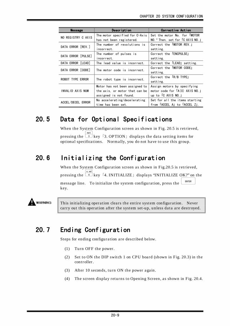
CHAPTER 20 SYSTEM CONFIGURATION
20-9
MessageMessageMessageMessage DescriptionDescriptionDescriptionDescription Corrective ActionCorrective ActionCorrective ActionCorrective Action
NO REGISTRY C AXISThe motor specified for C-Axis
has not been registered.
Set the motor No. for 「MOTOR
NO.” Then, set for 「C AXIS NO.」
DATA ERROR [REV.]The number of revolutions is
incorrect.
Correct the 「MOTOR REV.」
setting.
DATA ERROR [PULSE]The number of pulses is
incorrect.
Correct the 「ENCPULSE」
setting.
DATA ERROR [LEAD] The lead value is incorrect. Correct the 「LEAD」 setting.
DATA ERROR [CODE] The motor code is incorrect.Correct the 「MOTOR CODE」
setting.
ROBOT TYPE ERROR The robot type is incorrect.Correct the 「R/B TYPE」
setting.
INVALID AXIS NUM
Motor has not been assigned to
the axis, or motor that can be
assigned is not found.
Assign motors by specifying
motor code for 「A(X) AXIS NO.」
up to 「C AXIS NO.」
ACCEL/DECEL ERRORNo accelerating/decelerating
time has been set.
Set for all the items starting
from 「ACCEL A」 to 「ACCEL Z」.
20.520.520.520.5 Data for Optional SpecificationsData for Optional SpecificationsData for Optional SpecificationsData for Optional SpecificationsWhen the System Configuration screen as shown in Fig. 20.5 is retrieved,
pressing the mot
3 key 「3. OPTION」 displays the data setting items foroptional specifications. Normally, you do not have to use this group.
20.620.620.620.6 Initializing the ConfigurationInitializing the ConfigurationInitializing the ConfigurationInitializing the ConfigurationWhen the System Configuration screen as shown in Fig.20.5 is retrieved,
pressing the s.ed
4 key 「4. INITIALIZE」 displays “INITIALIZE OK?” on the
message line. To initialize the system configuration, press the ENTER
key.
This initializing operation clears the entire system configuration. Nevercarry out this operation after the system set-up, unless data are destroyed.
20.720.720.720.7 Ending ConfigurationEnding ConfigurationEnding ConfigurationEnding ConfigurationSteps for ending configuration are described below.
(1) Turn OFF the power.
(2) Set to ON the DIP switch 1 on CPU board (shown in Fig. 20.3) in thecontroller.
(3) After 10 seconds, turn ON the power again.
(4) The screen display returns to Opening Screen, as shown in Fig. 20.4.
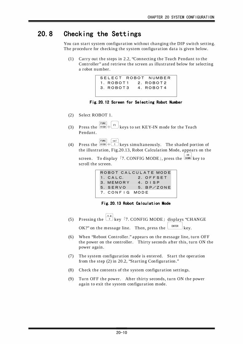
CHAPTER 20 SYSTEM CONFIGURATION
20-10
20.820.820.820.8 Checking the SettingsChecking the SettingsChecking the SettingsChecking the SettingsYou can start system configuration without changing the DIP switch setting.The procedure for checking the system configuration data is given below.
(1) Carry out the steps in 2.2, “Connecting the Teach Pendant to theController” and retrieve the screen as illustrated below for selectinga robot number.
SELECT ROBOT NUMBER
1.ROBOT1 2.ROBOT2
3.ROBOT3 4.ROBOT4
Fig.20.Fig.20.Fig.20.Fig.20.12121212 Screen for Selecting Robot Number Screen for Selecting Robot Number Screen for Selecting Robot Number Screen for Selecting Robot Number
(2) Select ROBOT 1.
(3) Press the FUNC
HIGH+F1 keys to set KEY-IN mode for the Teach
Pendant.
(4) Press the FUNC
HIGH+cal
1 keys simultaneously. The shaded portion ofthe illustration, Fig.20.13, Robot Calculation Mode, appears on the
screen. To display 「7. CONFIG MODE」, press the up
DOWN key toscroll the screen.
ROBOT CALCULATE MODE1.CALC. 2.OFFSET
3.MEMORY 4.DISP
5.SERVO 5.BP/ZONE7.CONFIG MODE
Fig.20.Fig.20.Fig.20.Fig.20.13131313 Robot Calculation Mode Robot Calculation Mode Robot Calculation Mode Robot Calculation Mode
(5) Pressing the s.g
7 key 「7. CONFIG MODE」 displays “CHANGE
OK?” on the message line. Then, press the ENTER key.
(6) When “Reboot Controller.” appears on the message line, turn OFFthe power on the controller. Thirty seconds after this, turn ON thepower again.
(7) The system configuration mode is entered. Start the operationfrom the step (2) in 20.2, “Starting Configuration.”
(8) Check the contents of the system configuration settings.
(9) Turn OFF the power. After thirty seconds, turn ON the poweragain to exit the system configuration mode.
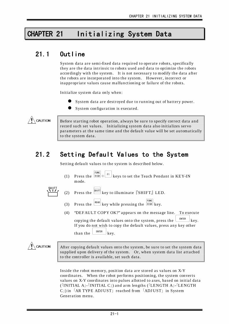
CHAPTER 21 INITIALIZING SYSTEM DATA
21-1
CHAPTER 21CHAPTER 21CHAPTER 21CHAPTER 21 Initializing System DataInitializing System DataInitializing System DataInitializing System Data
21.121.121.121.1 OutlineOutlineOutlineOutlineSystem data are semi-fixed data required to operate robots, specificallythey are the data intrinsic to robots used and data to optimize the robotsaccordingly with the system. It is not necessary to modify the data afterthe robots are incorporated into the system. However, incorrect orinappropriate values cause malfunctioning or failure of the robots.
Initialize system data only when:
System data are destroyed due to running out of battery power.
System configuration is executed.
Before starting robot operation, always be sure to specify correct data andrecord such set values. Initializing system data also initializes servoparameters at the same time and the default value will be set automaticallyto the system data.
21.221.221.221.2 Setting Default Values to the SystemSetting Default Values to the SystemSetting Default Values to the SystemSetting Default Values to the SystemSetting default values to the system is described below.
(1) Press the FUNC
HIGH+F1 keys to set the Teach Pendant in KEY-IN
mode.
(2) Press the SHIFT
key to illuminate『SHIFT』LED.
(3) Press the READ key while pressing the FUNC
HIGH key.
(4) “DEFAULT COPY OK?” appears on the message line. To execute
copying the default values onto the system, press the ENTER key.If you do not wish to copy the default values, press any key other
than the ENTER key.
After copying default values onto the system, be sure to set the system datasupplied upon delivery of the system. Or, when system data list attachedto the controller is available, set such data.
Inside the robot memory, position data are stored as values on X-Ycoordinates. When the robot performs positioning, the system convertsvalues on X-Y coordinates into pulses allotted to axes, based on initial data(「INITIAL A」-「INITIAL C」) and arm lengths (「LENGTH A」-「LENGTHC」) in 「AR TYPE ADJUST」 reached from 「ADJUST」 in SystemGeneration menu.
SHIFT
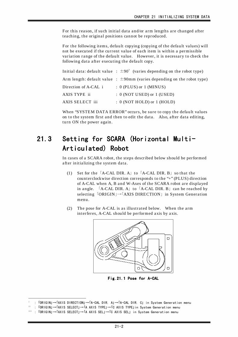
CHAPTER 21 INITIALIZING SYSTEM DATA
21-2
For this reason, if such initial data and/or arm lengths are changed afterteaching, the original positions cannot be reproduced.
For the following items, default copying (copying of the default values) willnot be executed if the current value of each item is within a permissiblevariation range of the default value. However, it is necessary to check thefollowing data after executing the default copy.
Initial data: default value : ±90°(varies depending on the robot type)
Arm length: default value : ±90mm (varies depending on the robot type)
Direction of A-CAL i : 0 (PLUS) or 1 (MINUS)
AXIS TYPE ii : 0 (NOT USED) or 1 (USED)
AXIS SELECT iii : 0 (NOT HOLD) or 1 (HOLD)
When “SYSTEM DATA ERROR” occurs, be sure to copy the default valueson to the system first and then to edit the data. Also, after data editing,turn ON the power again.
21.321.321.321.3 Setting for SCARA (Horizontal Multi-Setting for SCARA (Horizontal Multi-Setting for SCARA (Horizontal Multi-Setting for SCARA (Horizontal Multi-
Articulated) RobotArticulated) RobotArticulated) RobotArticulated) RobotIn cases of a SCARA robot, the steps described below should be performedafter initializing the system data.
(1) Set for the 「A-CAL DIR. A」 to 「A-CAL DIR. B」 so that thecounterclockwise direction corresponds to the “+” (PLUS) directionof A-CAL when A, B and W-Axes of the SCARA robot are displayedin angle. 「A-CAL DIR. A」 to 「A-CAL DIR. B」 can be reached byselecting 「ORIGIN」→「AXIS DIRECTION」 in System Generationmenu.
(2) The pose for A-CAL is as illustrated below. When the arminterferes, A-CAL should be performed axis by axis.
Fig.21.Fig.21.Fig.21.Fig.21.1111 Pose for A-CAL Pose for A-CAL Pose for A-CAL Pose for A-CAL
i : 「ORIGIN」→「AXIS DIRECTION」→「A-CAL DIR. A」→「A-CAL DIR. C」 in System Generation menuii : 「ORIGIN」→「AXIS SELECT」→「A AXIS TYPE」→「C AXIS TYPE」in System Generation menuiii : 「ORIGIN」→「AXIS SELECT」→「A AXIS SEL」→「C AXIS SEL」 in System Generation menu
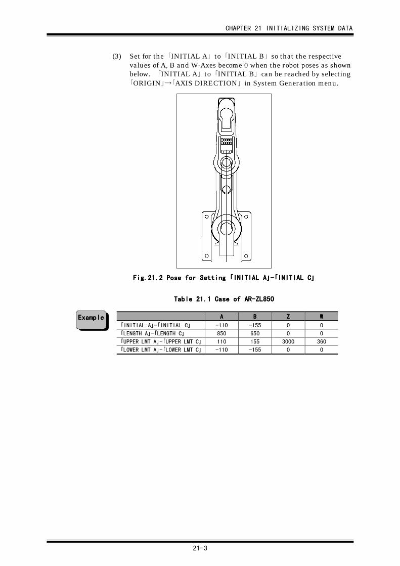
CHAPTER 21 INITIALIZING SYSTEM DATA
21-3
(3) Set for the 「INITIAL A」 to 「INITIAL B」 so that the respectivevalues of A, B and W-Axes become 0 when the robot poses as shownbelow. 「INITIAL A」 to 「INITIAL B」 can be reached by selecting「ORIGIN」→「AXIS DIRECTION」 in System Generation menu.
Fig.21.Fig.21.Fig.21.Fig.21.2222 Pose for Setting Pose for Setting Pose for Setting Pose for Setting 「「「「INITIAL AINITIAL AINITIAL AINITIAL A」」」」----「「「「INITIAL CINITIAL CINITIAL CINITIAL C」」」」
Table 21.Table 21.Table 21.Table 21.1111 Case of AR-ZL850 Case of AR-ZL850 Case of AR-ZL850 Case of AR-ZL850
AAAA BBBB ZZZZ WWWW
「INITIAL A」-「INITIAL C」 -110 -155 0 0
「LENGTH A」-「LENGTH C」 850 650 0 0
「UPPER LMT A」-「UPPER LMT C」 110 155 3000 360
「LOWER LMT A」-「LOWER LMT C」 -110 -155 0 0
ExampleExampleExampleExample
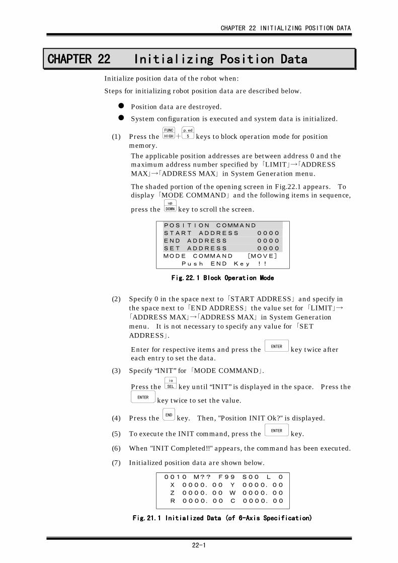
CHAPTER 22 INITIALIZING POSITION DATA
22-1
CHAPTER 22CHAPTER 22CHAPTER 22CHAPTER 22 Initializing Position DataInitializing Position DataInitializing Position DataInitializing Position Data
Initialize position data of the robot when:
Steps for initializing robot position data are described below.
Position data are destroyed.
System configuration is executed and system data is initialized.
(1) Press the FUNC
HIGH+p.ed
5 keys to block operation mode for positionmemory.The applicable position addresses are between address 0 and themaximum address number specified by 「LIMIT」→「ADDRESSMAX」→「ADDRESS MAX」 in System Generation menu.
The shaded portion of the opening screen in Fig.22.1 appears. Todisplay 「MODE COMMAND」 and the following items in sequence,
press the up
DOWN key to scroll the screen.
POSITION COMMAND
START ADDRESS 0000
END ADDRESS 0000
SET ADDRESS 0000
MODE COMMAND [MOVE]
Push END Key !!
Fig.22.Fig.22.Fig.22.Fig.22.1111 Block Operation Mode Block Operation Mode Block Operation Mode Block Operation Mode
(2) Specify 0 in the space next to 「START ADDRESS」 and specify inthe space next to 「END ADDRESS」 the value set for 「LIMIT」→「ADDRESS MAX」→「ADDRESS MAX」 in System Generationmenu. It is not necessary to specify any value for 「SETADDRESS」.
Enter for respective items and press the ENTER key twice aftereach entry to set the data.
(3) Specify “INIT” for 「MODE COMMAND」.
Press the io
SEL key until “INIT” is displayed in the space. Press theENTER key twice to set the value.
(4) Press the END key. Then, "Position INIT Ok?" is displayed.
(5) To execute the INIT command, press the ENTER key.
(6) When "INIT Completed!!" appears, the command has been executed.
(7) Initialized position data are shown below.
0010 M?? F99 S00 L 0
X 0000.00 Y 0000.00
Z 0000.00 W 0000.00
R 0000.00 C 0000.00
Fig.21.Fig.21.Fig.21.Fig.21.1111 Initialized Data (of 6-Axis Specification) Initialized Data (of 6-Axis Specification) Initialized Data (of 6-Axis Specification) Initialized Data (of 6-Axis Specification)
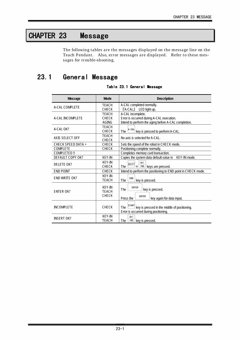
CHAPTER 23 MESSAGE
23-1
CHAPTER 23CHAPTER 23CHAPTER 23CHAPTER 23 MessageMessageMessageMessage
The following tables are the messages displayed on the message line on theTeach Pendant. Also, error messages are displayed. Refer to these mes-sages for trouble-shooting.
23.123.123.123.1 General MessageGeneral MessageGeneral MessageGeneral MessageTable 23.Table 23.Table 23.Table 23.1111 General Message General Message General Message General Message
Message Mode Description
A-CAL COMPLETE TEACHCHECK
A-CAL completed normally.『A-CAL』 LED light up.
A-CAL INCOMPLETETEACHCHECKAGING
A-CAL incomplete.Error is occurred during A-CAL execution.Intend to perform the aging before A-CAL completion.
A-CAL OK? TEACHCHECK The A-CAL key is pressed to perform A-CAL.
AXIS SELECT OFF TEACHCHECK No axis is selected for A-CAL.
CHECK SPEED DATA > CHECK Sets the speed of the robot in CHECK mode.COMPLETE CHECK Positioning complete normally.COMPLETED !! Completes memory card transaction.DEFAULT COPY OK? KEY-IN Copies the system data default value in KEY-IN mode.
DELETE OK? KEY-INCHECK The
SHIFT+
del
INS keys are pressed.END POINT CHECK Intend to perform the positioning to END point in CHECK mode.
END WRITE OK? KEY-INTEACH The END key is pressed.
ENTER OK?KEY-INTEACHCHECK
The ENTER key is pressed.
Press the ENTER key again for data input.
INCOMPLETE CHECK The START key is pressed in the middle of positioning.Error is occurred during positioning.
INSERT OK? KEY-INTEACH The
del
INS key is pressed.
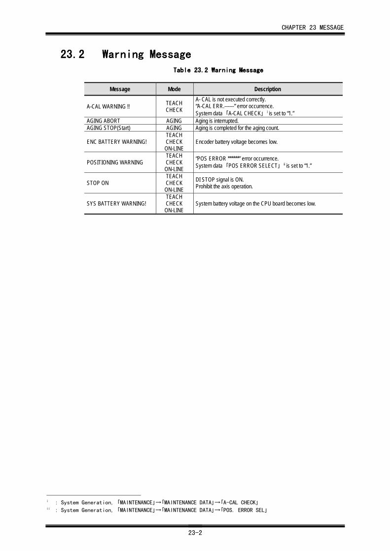
CHAPTER 23 MESSAGE
23-2
23.223.223.223.2 Warning MessageWarning MessageWarning MessageWarning MessageTable 23.Table 23.Table 23.Table 23.2222 Warning Message Warning Message Warning Message Warning Message
Message Mode Description
A-CAL WARNING !! TEACHCHECK
A- CAL is not executed correctly.“A-CAL ERR.------” error occurrence.System data 「A-CAL CHECK」 i is set to “1.”
AGING ABORT AGING Aging is interrupted.AGING STOP(Start) AGING Aging is completed for the aging count.
ENC BATTERY WARNING!TEACHCHECKON-LINE
Encoder battery voltage becomes low.
POSITIONING WARNINGTEACHCHECKON-LINE
“POS ERROR ******” error occurrence.System data 「POS ERROR SELECT」 ii is set to “1.”
STOP ONTEACHCHECKON-LINE
DI STOP signal is ON.Prohibit the axis operation.
SYS BATTERY WARNING!TEACHCHECKON-LINE
System battery voltage on the CPU board becomes low.
i : System Generation, 「MAINTENANCE」→「MAINTENANCE DATA」→「A-CAL CHECK」ii : System Generation, 「MAINTENANCE」→「MAINTENANCE DATA」→「POS. ERROR SEL」
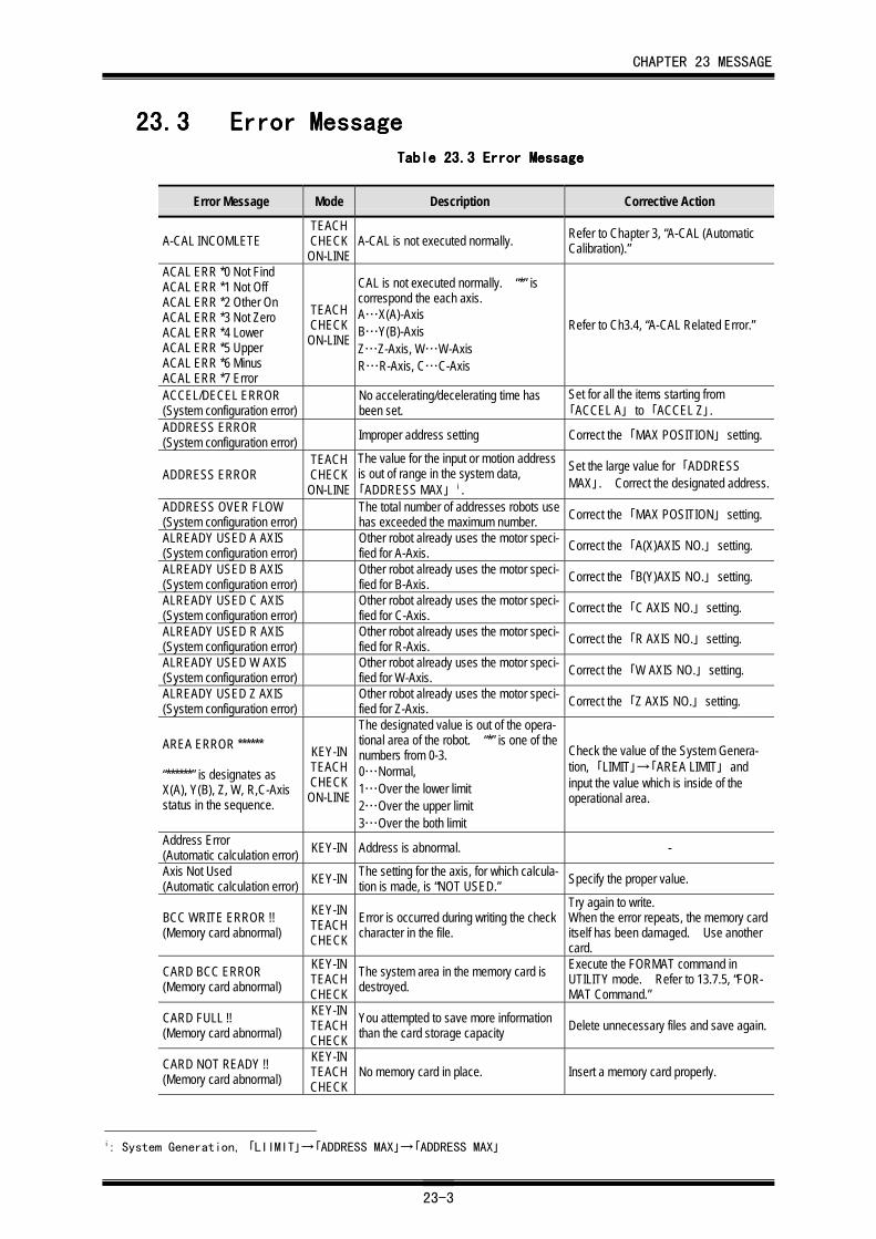
CHAPTER 23 MESSAGE
23-3
23.323.323.323.3 Error MessageError MessageError MessageError MessageTable 23.Table 23.Table 23.Table 23.3333 Error Message Error Message Error Message Error Message
Error Message Mode Description Corrective Action
A-CAL INCOMLETETEACHCHECKON-LINE
A-CAL is not executed normally. Refer to Chapter 3, “A-CAL (AutomaticCalibration).”
ACAL ERR *0 Not FindACAL ERR *1 Not OffACAL ERR *2 Other OnACAL ERR *3 Not ZeroACAL ERR *4 LowerACAL ERR *5 UpperACAL ERR *6 MinusACAL ERR *7 Error
TEACHCHECKON-LINE
CAL is not executed normally. “*” iscorrespond the each axis.A…X(A)-AxisB…Y(B)-AxisZ…Z-Axis, W…W-AxisR…R-Axis, C…C-Axis
Refer to Ch3.4, “A-CAL Related Error.”
ACCEL/DECEL ERROR(System configuration error)
No accelerating/decelerating time hasbeen set.
Set for all the items starting from「ACCEL A」 to 「ACCEL Z」.
ADDRESS ERROR(System configuration error) Improper address setting Correct the 「MAX POSITION」 setting.
ADDRESS ERRORTEACHCHECKON-LINE
The value for the input or motion addressis out of range in the system data,「ADDRESS MAX」 i .
Set the large value for 「ADDRESSMAX」. Correct the designated address.
ADDRESS OVER FLOW(System configuration error)
The total number of addresses robots usehas exceeded the maximum number. Correct the 「MAX POSITION」 setting.
ALREADY USED A AXIS(System configuration error)
Other robot already uses the motor speci-fied for A-Axis. Correct the 「A(X)AXIS NO.」 setting.
ALREADY USED B AXIS(System configuration error)
Other robot already uses the motor speci-fied for B-Axis. Correct the 「B(Y)AXIS NO.」 setting.
ALREADY USED C AXIS(System configuration error)
Other robot already uses the motor speci-fied for C-Axis. Correct the 「C AXIS NO.」 setting.
ALREADY USED R AXIS(System configuration error)
Other robot already uses the motor speci-fied for R-Axis. Correct the 「R AXIS NO.」 setting.
ALREADY USED W AXIS(System configuration error)
Other robot already uses the motor speci-fied for W-Axis. Correct the 「W AXIS NO.」 setting.
ALREADY USED Z AXIS(System configuration error)
Other robot already uses the motor speci-fied for Z-Axis. Correct the 「Z AXIS NO.」 setting.
AREA ERROR ******
“******” is designates asX(A), Y(B), Z, W, R,C-Axisstatus in the sequence.
KEY-INTEACHCHECKON-LINE
The designated value is out of the opera-tional area of the robot. “*” is one of thenumbers from 0-3.0…Normal,1…Over the lower limit2…Over the upper limit3…Over the both limit
Check the value of the System Genera-tion, 「LIMIT」→「AREA LIMIT」 andinput the value which is inside of theoperational area.
Address Error(Automatic calculation error) KEY-IN Address is abnormal. -
Axis Not Used(Automatic calculation error) KEY-IN The setting for the axis, for which calcula-
tion is made, is “NOT USED.” Specify the proper value.
BCC WRITE ERROR !!(Memory card abnormal)
KEY-INTEACHCHECK
Error is occurred during writing the checkcharacter in the file.
Try again to write.When the error repeats, the memory carditself has been damaged. Use anothercard.
CARD BCC ERROR(Memory card abnormal)
KEY-INTEACHCHECK
The system area in the memory card isdestroyed.
Execute the FORMAT command inUTILITY mode. Refer to 13.7.5, “FOR-MAT Command.”
CARD FULL !!(Memory card abnormal)
KEY-INTEACHCHECK
You attempted to save more informationthan the card storage capacity Delete unnecessary files and save again.
CARD NOT READY !!(Memory card abnormal)
KEY-INTEACHCHECK
No memory card in place. Insert a memory card properly.
i: System Generation, 「LIIMIT」→「ADDRESS MAX」→「ADDRESS MAX」
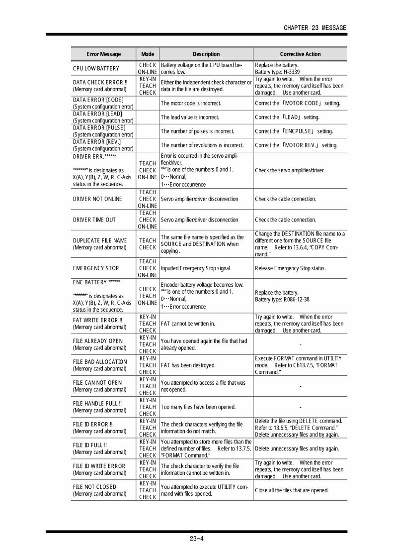
CHAPTER 23 MESSAGE
23-4
Error Message Mode Description Corrective Action
CPU LOW BATTERY CHECKON-LINE
Battery voltage on the CPU board be-comes low.
Replace the battery.Battery type: H-3339
DATA CHECK ERROR !!(Memory card abnormal)
KEY-INTEACHCHECK
Either the independent check character ordata in the file are destroyed.
Try again to write. When the errorrepeats, the memory card itself has beendamaged. Use another card.
DATA ERROR [CODE](System configuration error) The motor code is incorrect. Correct the 「MOTOR CODE」 setting.
DATA ERROR [LEAD](System configuration error) The lead value is incorrect. Correct the 「LEAD」 setting.
DATA ERROR [PULSE](System configuration error) The number of pulses is incorrect. Correct the 「ENCPULSE」 setting.
DATA ERROR [REV.](System configuration error) The number of revolutions is incorrect. Correct the 「MOTOR REV.」 setting.
DRIVER ERR.******
“******” is designates asX(A), Y(B), Z, W, R, C-Axisstatus in the sequence.
TEACHCHECKON-LINE
Error is occurred in the servo ampli-fier/driver.“*” is one of the numbers 0 and 1.0…Normal,1…Error occurrence
Check the servo amplifier/driver.
DRIVER NOT ONLINETEACHCHECKON-LINE
Servo amplifier/driver disconnection Check the cable connection.
DRIVER TIME OUTTEACHCHECKON-LINE
Servo amplifier/driver disconnection Check the cable connection.
DUPLICATE FILE NAME(Memory card abnormal)
TEACHCHECK
The same file name is specified as theSOURCE and DESTINATION whencopying .
Change the DESTINATION file name to adifferent one form the SOURCE filename. Refer to 13.6.4, “COPY Com-mand.”
EMERGENCY STOPTEACHCHECKON-LINE
Inputted Emergency Stop signal Release Emergency Stop status.
ENC BATTERY ******
“******” is designates asX(A), Y(B), Z, W, R, C-Axisstatus in the sequence.
CHECKTEACH
ON-LINE
Encoder battery voltage becomes low.“*” is one of the numbers 0 and 1.0…Normal,1…Error occurrence
Replace the battery.Battery type: R086-12-38
FAT WRITE ERROR !!(Memory card abnormal)
KEY-INTEACHCHECK
FAT cannot be written in.Try again to write. When the errorrepeats, the memory card itself has beendamaged. Use another card.
FILE ALREADY OPEN(Memory card abnormal)
KEY-INTEACHCHECK
You have opened again the file that hadalready opened. -
FILE BAD ALLOCATION(Memory card abnormal)
KEY-INTEACHCHECK
FAT has been destroyed.Execute FORMAT command in UTILITYmode. Refer to Ch13.7.5, “FORMATCommand.”
FILE CAN NOT OPEN(Memory card abnormal)
KEY-INTEACHCHECK
You attempted to access a file that wasnot opened. -
FILE HANDLE FULL !!(Memory card abnormal)
KEY-INTEACHCHECK
Too many files have been opened. -
FILE ID ERROR !!(Memory card abnormal)
KEY-INTEACHCHECK
The check characters verifying the fileinformation do not match.
Delete the file using DELETE command.Refer to 13.6.5, “DELETE Command.”Delete unnecessary files and try again.
FILE ID FULL !!(Memory card abnormal)
KEY-INTEACHCHECK
You attempted to store more files than thedefined number of files. Refer to 13.7.5,“FORMAT Command.”
Delete unnecessary files and try again.
FILE ID WRITE ERROR(Memory card abnormal)
KEY-INTEACHCHECK
The check character to verify the fileinformation cannot be written in.
Try again to write. When the errorrepeats, the memory card itself has beendamaged. Use another card.
FILE NOT CLOSED(Memory card abnormal)
KEY-INTEACHCHECK
You attempted to execute UTILITY com-mand with files opened. Close all the files that are opened.
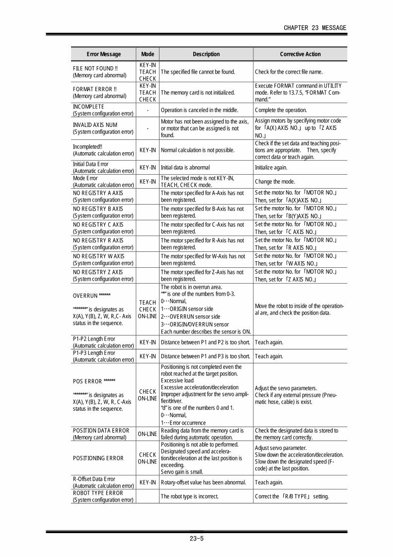
CHAPTER 23 MESSAGE
23-5
Error Message Mode Description Corrective Action
FILE NOT FOUND !!(Memory card abnormal)
KEY-INTEACHCHECK
The specified file cannot be found. Check for the correct file name.
FORMAT ERROR !!(Memory card abnormal)
KEY-INTEACHCHECK
The memory card is not initialized.Execute FORMAT command in UTILITYmode. Refer to 13.7.5, “FORMAT Com-mand.”
INCOMPLETE(System configuration error) - Operation is canceled in the middle. Complete the operation.
INVALID AXIS NUM(System configuration error) -
Motor has not been assigned to the axis,or motor that can be assigned is notfound.
Assign motors by specifying motor codefor 「A(X) AXIS NO.」 up to 「Z AXISNO.」
Incompleted!!(Automatic calculation error) KEY-IN Normal calculation is not possible.
Check if the set data and teaching posi-tions are appropriate. Then, specifycorrect data or teach again.
Initial Data Error(Automatic calculation error) KEY-IN Initial data is abnormal Initialize again.
Mode Error(Automatic calculation error) KEY-IN The selected mode is not KEY-IN,
TEACH, CHECK mode. Change the mode.
NO REGISTRY A AXIS(System configuration error)
The motor specified for A-Axis has notbeen registered.
Set the motor No. for 「MOTOR NO.」Then, set for 「A(X)AXIS NO.」
NO REGISTRY B AXIS(System configuration error)
The motor specified for B-Axis has notbeen registered.
Set the motor No. for 「MOTOR NO.」Then, set for 「B(Y)AXIS NO.」
NO REGISTRY C AXIS(System configuration error)
The motor specified for C-Axis has notbeen registered.
Set the motor No. for 「MOTOR NO.」Then, set for 「C AXIS NO.」
NO REGISTRY R AXIS(System configuration error)
The motor specified for R-Axis has notbeen registered.
Set the motor No. for 「MOTOR NO.」Then, set for 「R AXIS NO.」
NO REGISTRY W AXIS(System configuration error)
The motor specified for W-Axis has notbeen registered.
Set the motor No. for 「MOTOR NO.」Then, set for 「W AXIS NO.」
NO REGISTRY Z AXIS(System configuration error)
The motor specified for Z-Axis has notbeen registered.
Set the motor No. for 「MOTOR NO.」Then, set for 「Z AXIS NO.」
OVERRUN ******
“******” is designates asX(A), Y(B), Z, W, R,C- Axisstatus in the sequence.
TEACHCHECKON-LINE
The robot is in overrun area.“*” is one of the numbers from 0-3.0…Normal,1…ORIGIN sensor side2…OVERRUN sensor side3…ORIGIN/OVERRUN sensorEach number describes the sensor is ON.
Move the robot to inside of the operation-al are, and check the position data.
P1-P2 Length Error(Automatic calculation error) KEY-IN Distance between P1 and P2 is too short. Teach again.
P1-P3 Length Error(Automatic calculation error) KEY-IN Distance between P1 and P3 is too short. Teach again.
POS ERROR ******
“******” is designates asX(A), Y(B), Z, W, R, C-Axisstatus in the sequence.
CHECKON-LINE
Positioning is not completed even therobot reached at the target position.Excessive loadExcessive acceleration/decelerationImproper adjustment for the servo ampli-fier/driver.“d” is one of the numbers 0 and 1.0…Normal,1…Error occurrence
Adjust the servo parameters.Check if any external pressure (Pneu-matic hose, cable) is exist.
POSITION DATA ERROR(Memory card abnormal) ON-LINE Reading data from the memory card is
failed during automatic operation.Check the designated data is stored tothe memory card correctly.
POSITIONING ERROR CHECKON-LINE
Positioning is not able to performed.Designated speed and accelera-tion/deceleration at the last position isexceeding.Servo gain is small.
Adjust servo parameter.Slow down the acceleration/deceleration.Slow down the designated speed (F-code) at the last position.
R-Offset Data Error(Automatic calculation error) KEY-IN Rotary-offset value has been abnormal. Teach again.
ROBOT TYPE ERROR(System configuration error) The robot type is incorrect. Correct the 「R/B TYPE」 setting.
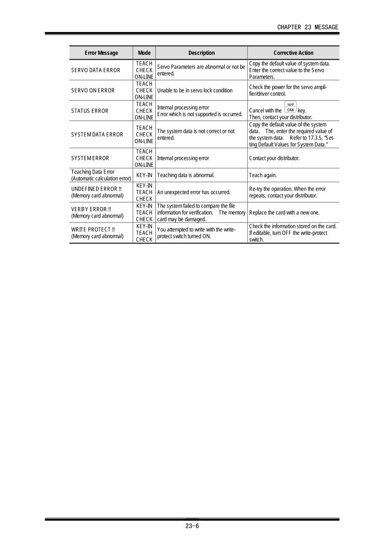
CHAPTER 23 MESSAGE
23-6
Error Message Mode Description Corrective Action
SERVO DATA ERRORTEACHCHECKON-LINE
Servo Parameters are abnormal or not beentered.
Copy the default value of system data.Enter the correct value to the ServoParameters.
SERVO ON ERRORTEACHCHECKON-LINE
Unable to be in servo lock condition Check the power for the servo ampli-fier/driver control.
STATUS ERRORTEACHCHECKON-LINE
Internal processing errorError which is not supported is occurred. Cancel with the
spd
CAN key.Then, contact your distributor.
SYSTEM DATA ERRORTEACHCHECKON-LINE
The system data is not correct or notentered.
Copy the default value of the systemdata. The, enter the required value ofthe system data. Refer to 17.3.5, “Set-ting Default Values for System Data.”
SYSTEM ERRORTEACHCHECKON-LINE
Internal processing error Contact your distributor.
Teaching Data Error(Automatic calculation error) KEY-IN Teaching data is abnormal. Teach again.
UNDEFINED ERROR !!(Memory card abnormal)
KEY-INTEACHCHECK
An unexpected error has occurred. Re-try the operation. When the errorrepeats, contact your distributor.
VERIFY ERROR !!(Memory card abnormal)
KEY-INTEACHCHECK
The system failed to compare the fileinformation for verification. The memorycard may be damaged.
Replace the card with a new one.
WRITE PROTECT !!(Memory card abnormal)
KEY-INTEACHCHECK
You attempted to write with the write-protect switch turned ON.
Check the information stored on the card.If editable, turn OFF the write-protectswitch.
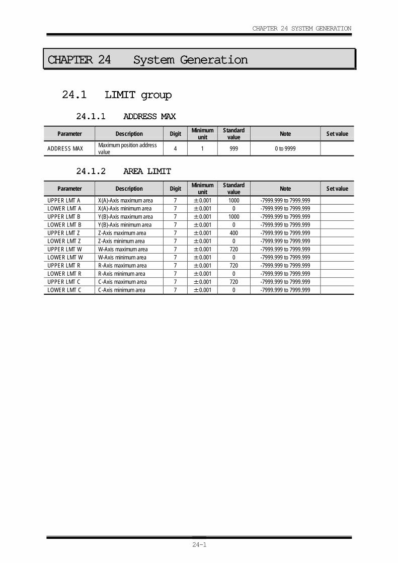
CHAPTER 24 SYSTEM GENERATION
24-1
CHAPTER 24CHAPTER 24CHAPTER 24CHAPTER 24 System GenerationSystem GenerationSystem GenerationSystem Generation
24.124.124.124.1 LIMIT groupLIMIT groupLIMIT groupLIMIT group
24.1.124.1.124.1.124.1.1 ADDRESS MAXADDRESS MAXADDRESS MAXADDRESS MAX
Parameter Description Digit Minimumunit
Standardvalue Note Set value
ADDRESS MAX Maximum position addressvalue 4 1 999 0 to 9999
24.1.224.1.224.1.224.1.2 AREA LIMITAREA LIMITAREA LIMITAREA LIMIT
Parameter Description Digit Minimumunit
Standardvalue Note Set value
UPPER LMT A X(A)-Axis maximum area 7 ±0.001 1000 -7999.999 to 7999.999LOWER LMT A X(A)-Axis minimum area 7 ±0.001 0 -7999.999 to 7999.999UPPER LMT B Y(B)-Axis maximum area 7 ±0.001 1000 -7999.999 to 7999.999LOWER LMT B Y(B)-Axis minimum area 7 ±0.001 0 -7999.999 to 7999.999UPPER LMT Z Z-Axis maximum area 7 ±0.001 400 -7999.999 to 7999.999LOWER LMT Z Z-Axis minimum area 7 ±0.001 0 -7999.999 to 7999.999UPPER LMT W W-Axis maximum area 7 ±0.001 720 -7999.999 to 7999.999LOWER LMT W W-Axis minimum area 7 ±0.001 0 -7999.999 to 7999.999UPPER LMT R R-Axis maximum area 7 ±0.001 720 -7999.999 to 7999.999LOWER LMT R R-Axis minimum area 7 ±0.001 0 -7999.999 to 7999.999UPPER LMT C C-Axis maximum area 7 ±0.001 720 -7999.999 to 7999.999LOWER LMT C C-Axis minimum area 7 ±0.001 0 -7999.999 to 7999.999
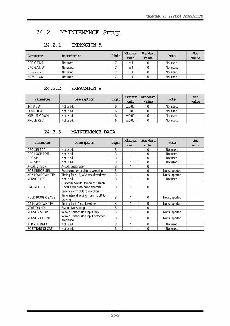
CHAPTER 24 SYSTEM GENERATION
24-2
24.224.224.224.2 MAINTENANCE GroupMAINTENANCE GroupMAINTENANCE GroupMAINTENANCE Group
24.2.124.2.124.2.124.2.1 EXPANSION AEXPANSION AEXPANSION AEXPANSION A
ParameterParameterParameterParameter DescriptionDescriptionDescriptionDescription DigitDigitDigitDigitMinimumMinimumMinimumMinimum
unitunitunitunit
StandardStandardStandardStandard
valuevaluevaluevalueNoteNoteNoteNote
SetSetSetSet
valuevaluevaluevalue
CPC GAIN Z Not used. 7 ±1 0 Not used.CPC GAIN W Not used. 7 ±1 0 Not used.DOWN CNT. Not used. 7 ±1 0 Not used.PRIV. FLAG Not used. 7 ±1 0 Not used.
24.2.224.2.224.2.224.2.2 EXPANSION BEXPANSION BEXPANSION BEXPANSION B
ParameterParameterParameterParameter DescriptionDescriptionDescriptionDescription DigitDigitDigitDigitMinimumMinimumMinimumMinimum
unitunitunitunit
StandardStandardStandardStandard
valuevaluevaluevalueNoteNoteNoteNote
SetSetSetSet
valuevaluevaluevalue
INITIAL W Not used. 6 ±0.001 0 Not used.LENGTH W Not used. 6 ±0.001 0 Not used.AXIS UP/DOWN Not used. 6 ±0.001 0 Not used.ANGLE REV. Not used. 6 ±0.001 0 Not used.
24.2.324.2.324.2.324.2.3 MAINTENANCE DATAMAINTENANCE DATAMAINTENANCE DATAMAINTENANCE DATA
ParameterParameterParameterParameter DescriptionDescriptionDescriptionDescription DigitDigitDigitDigitMinimumMinimumMinimumMinimum
unitunitunitunit
StandardStandardStandardStandard
valuevaluevaluevalueNoteNoteNoteNote
SetSetSetSet
valuevaluevaluevalue
CPC SELECT Not used. 3 1 0 Not used.CPC LOOP TIME Not used. 3 1 0 Not used.CPC SP1 Not used. 3 1 0 Not used.CPC SP2 Not used. 3 1 0 Not used.A-CAL CHECK A-CAL designation 3 1 0POS.ERROR SEL Positioning error detect selection 3 1 0 Not supportedAB SLOWDOWN TIM Timing for A, B, W-Axes slow down 3 1 0 Not supportedSERVO TYPE Not used. 3 1 0 Not used.
EMP SELECT(Encoder Monitor Program Select)Driver error detect and encoderbattery alarm detect selection
3 1 0
HOLD POWER SAVE Time interval setting from HOLD tobraking 3 1 0 Not supported
Z SLOWDOWN TIM Timing for Z-Axis slow down 3 1 0 Not supportedSTATION NO Station No. setting 3 1 0SENSOR STOP SEL W-Axis sensor stop input logic 3 1 0 Not supported
SENSOR COUNT W-Axis sensor stop input detectionamplitude 3 1 0 Not supported
PTP Z IN DATA Not used. 3 1 0 Not used.POSITIONING CNT Not used. 3 1 0 Not used.
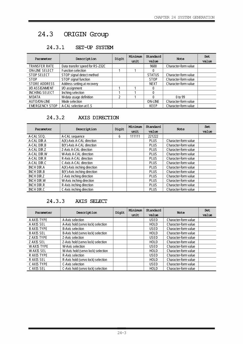
CHAPTER 24 SYSTEM GENERATION
24-3
24.324.324.324.3 ORIGIN GroupORIGIN GroupORIGIN GroupORIGIN Group
24.3.124.3.124.3.124.3.1 SET-UP SYSTEMSET-UP SYSTEMSET-UP SYSTEMSET-UP SYSTEM
ParameterParameterParameterParameter DescriptionDescriptionDescriptionDescription DigitDigitDigitDigitMinimumMinimumMinimumMinimum
unitunitunitunit
StandardStandardStandardStandard
valuevaluevaluevalueNoteNoteNoteNote
SetSetSetSet
valuevaluevaluevalue
TRANSFER RATE Data transfer speed for RS-232C 9600 Character-form valueON-LINE SELECT Function selection 1 1 0STOP SELECT STOP signal detect method STATUS Character-form valueSTOP STOP signal function STOP Character-form valueSTORE ADDRESS Address setting at recovery NEXT Character-form valueI/O ASSIGNMENT I/O assignment 1 1 0INCHING SELECT Inching selection 1 1 0M DATA M-data usage definition 2 1 0 0 to 99AUTO/ON-LINE Mode selection ON-LINE Character-form valueEMERGENCY STOP A-CAL selection at E.S KEEP Character-form value
24.3.224.3.224.3.224.3.2 AXIS DIRECTIONAXIS DIRECTIONAXIS DIRECTIONAXIS DIRECTION
ParameterParameterParameterParameter DescriptionDescriptionDescriptionDescription DigitDigitDigitDigitMinimumMinimumMinimumMinimum
unitunitunitunit
StandardStandardStandardStandard
valuevaluevaluevalueNoteNoteNoteNote
SetSetSetSet
valuevaluevaluevalue
A-CAL SEQ. A-CAL sequence 6 111111 221222A-CAL DIR.A A(X)-Axis A-CAL direction PLUS Character-form valueA-CAL DIR.B B(Y)-Axis A-CAL direction PLUS Character-form valueA-CAL DIR.Z Z-Axis A-CAL direction PLUS Character-form valueA-CAL DIR.W W-Axis A-CAL direction PLUS Character-form valueA-CAL DIR.R R-Axis A-CAL direction PLUS Character-form valueA-CAL DIR.C C-Axis A-CAL direction PLUS Character-form valueINCH DIR.A A(X)-Axis inching direction PLUS Character-form valueINCH DIR.B B(Y)-Axis inching direction PLUS Character-form valueINCH DIR.Z Z-Axis inching direction PLUS Character-form valueINCH DIR.W W-Axis inching direction PLUS Character-form valueINCH DIR.R R-Axis inching direction PLUS Character-form valueINCH DIR.C C-Axis inching direction PLUS Character-form value
24.3.324.3.324.3.324.3.3 AXIS SELECTAXIS SELECTAXIS SELECTAXIS SELECT
ParameterParameterParameterParameter DescriptionDescriptionDescriptionDescription DigitDigitDigitDigitMinimumMinimumMinimumMinimum
unitunitunitunit
StandardStandardStandardStandard
valuevaluevaluevalueNoteNoteNoteNote
SetSetSetSet
valuevaluevaluevalue
A AXIS TYPE A-Axis selection USED Character-form valueA AXIS SEL A-Axis hold (servo lock) selection HOLD Character-form valueB AXIS TYPE B-Axis selection USED Character-form valueB AXIS SEL B-Axis hold (servo lock) selection HOLD Character-form valueZ AXIS TYPE Z-Axis selection USED Character-form valueZ AXIS SEL Z-Axis hold (servo lock) selection HOLD Character-form valueW AXIS TYPE W-Axis selection USED Character-form valueW AXIS SEL W-Axis hold (servo lock) selection HOLD Character-form valueR AXIS TYPE R-Axis selection USED Character-form valueR AXIS SEL R-Axis hold (servo lock) selection HOLD Character-form valueC AXIS TYPE C-Axis selection USED Character-form valueC AXIS SEL C-Axis hold (servo lock) selection HOLD Character-form value
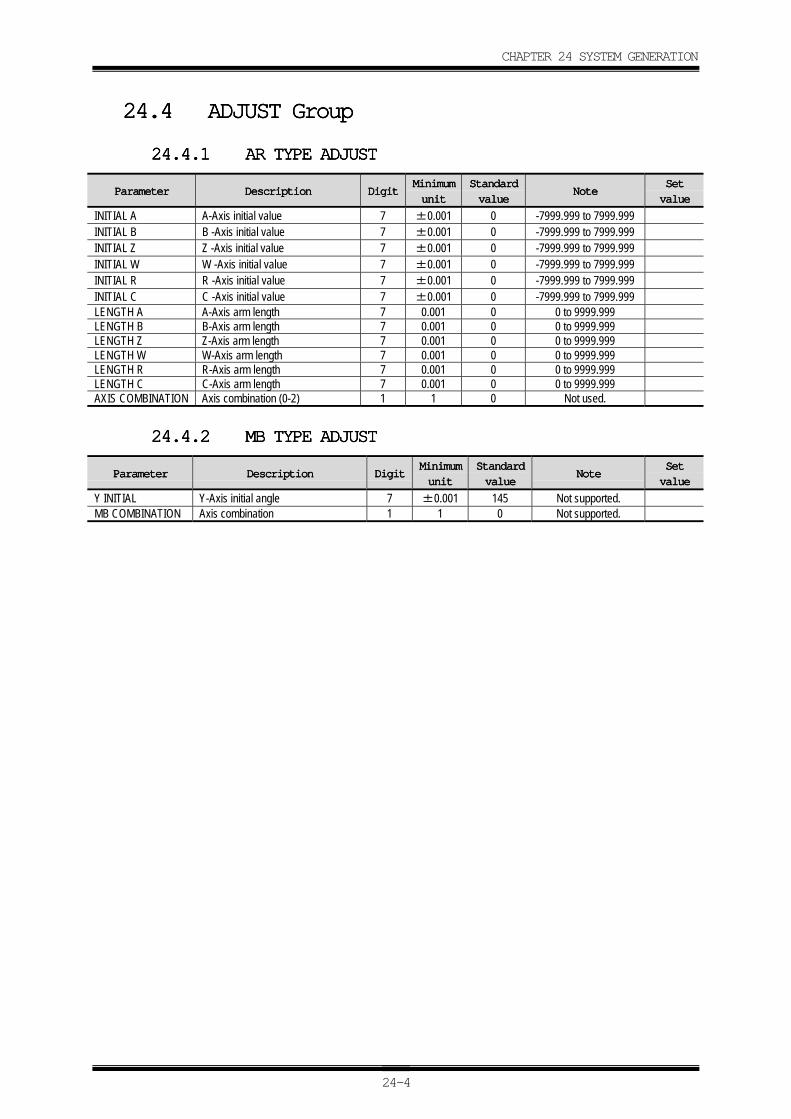
CHAPTER 24 SYSTEM GENERATION
24-4
24.424.424.424.4 ADJUST GroupADJUST GroupADJUST GroupADJUST Group
24.4.124.4.124.4.124.4.1 AR TYPE ADJUSTAR TYPE ADJUSTAR TYPE ADJUSTAR TYPE ADJUST
ParameterParameterParameterParameter DescriptionDescriptionDescriptionDescription DigitDigitDigitDigitMinimumMinimumMinimumMinimum
unitunitunitunit
StandardStandardStandardStandard
valuevaluevaluevalueNoteNoteNoteNote
SetSetSetSet
valuevaluevaluevalue
INITIAL A A-Axis initial value 7 ±0.001 0 -7999.999 to 7999.999INITIAL B B -Axis initial value 7 ±0.001 0 -7999.999 to 7999.999INITIAL Z Z -Axis initial value 7 ±0.001 0 -7999.999 to 7999.999INITIAL W W -Axis initial value 7 ±0.001 0 -7999.999 to 7999.999INITIAL R R -Axis initial value 7 ±0.001 0 -7999.999 to 7999.999INITIAL C C -Axis initial value 7 ±0.001 0 -7999.999 to 7999.999LENGTH A A-Axis arm length 7 0.001 0 0 to 9999.999LENGTH B B-Axis arm length 7 0.001 0 0 to 9999.999LENGTH Z Z-Axis arm length 7 0.001 0 0 to 9999.999LENGTH W W-Axis arm length 7 0.001 0 0 to 9999.999LENGTH R R-Axis arm length 7 0.001 0 0 to 9999.999LENGTH C C-Axis arm length 7 0.001 0 0 to 9999.999AXIS COMBINATION Axis combination (0-2) 1 1 0 Not used.
24.4.224.4.224.4.224.4.2 MB TYPE ADJUSTMB TYPE ADJUSTMB TYPE ADJUSTMB TYPE ADJUST
ParameterParameterParameterParameter DescriptionDescriptionDescriptionDescription DigitDigitDigitDigitMinimumMinimumMinimumMinimum
unitunitunitunit
StandardStandardStandardStandard
valuevaluevaluevalueNoteNoteNoteNote
SetSetSetSet
valuevaluevaluevalue
Y INITIAL Y-Axis initial angle 7 ±0.001 145 Not supported.MB COMBINATION Axis combination 1 1 0 Not supported.
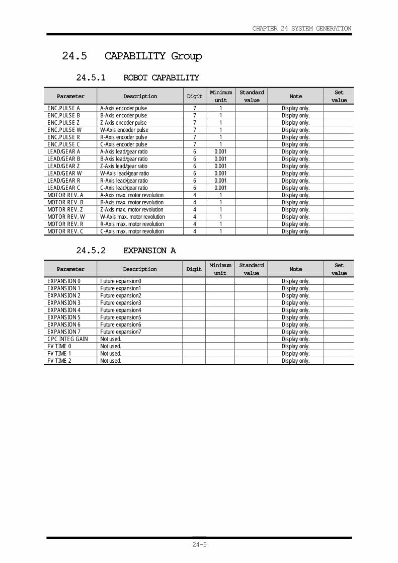
CHAPTER 24 SYSTEM GENERATION
24-5
24.524.524.524.5 CAPABILITY GroupCAPABILITY GroupCAPABILITY GroupCAPABILITY Group
24.5.124.5.124.5.124.5.1 ROBOT CAPABILITYROBOT CAPABILITYROBOT CAPABILITYROBOT CAPABILITY
ParameterParameterParameterParameter DescriptionDescriptionDescriptionDescription DigitDigitDigitDigitMinimumMinimumMinimumMinimum
unitunitunitunit
StandardStandardStandardStandard
valuevaluevaluevalueNoteNoteNoteNote
SetSetSetSet
valuevaluevaluevalue
ENC.PULSE A A-Axis encoder pulse 7 1 Display only.ENC.PULSE B B-Axis encoder pulse 7 1 Display only.ENC.PULSE Z Z-Axis encoder pulse 7 1 Display only.ENC.PULSE W W-Axis encoder pulse 7 1 Display only.ENC.PULSE R R-Axis encoder pulse 7 1 Display only.ENC.PULSE C C-Axis encoder pulse 7 1 Display only.LEAD/GEAR A A-Axis lead/gear ratio 6 0.001 Display only.LEAD/GEAR B B-Axis lead/gear ratio 6 0.001 Display only.LEAD/GEAR Z Z-Axis lead/gear ratio 6 0.001 Display only.LEAD/GEAR W W-Axis lead/gear ratio 6 0.001 Display only.LEAD/GEAR R R-Axis lead/gear ratio 6 0.001 Display only.LEAD/GEAR C C-Axis lead/gear ratio 6 0.001 Display only.MOTOR REV. A A-Axis max. motor revolution 4 1 Display only.MOTOR REV. B B-Axis max. motor revolution 4 1 Display only.MOTOR REV. Z Z-Axis max. motor revolution 4 1 Display only.MOTOR REV. W W-Axis max. motor revolution 4 1 Display only.MOTOR REV. R R-Axis max. motor revolution 4 1 Display only.MOTOR REV. C C-Axis max. motor revolution 4 1 Display only.
24.5.224.5.224.5.224.5.2 EXPANSION AEXPANSION AEXPANSION AEXPANSION A
ParameterParameterParameterParameter DescriptionDescriptionDescriptionDescription DigitDigitDigitDigitMinimumMinimumMinimumMinimum
unitunitunitunit
StandardStandardStandardStandard
valuevaluevaluevalueNoteNoteNoteNote
SetSetSetSet
valuevaluevaluevalue
EXPANSION 0 Future expansion0 Display only.EXPANSION 1 Future expansion1 Display only.EXPANSION 2 Future expansion2 Display only.EXPANSION 3 Future expansion3 Display only.EXPANSION 4 Future expansion4 Display only.EXPANSION 5 Future expansion5 Display only.EXPANSION 6 Future expansion6 Display only.EXPANSION 7 Future expansion7 Display only.CPC INTEG GAIN Not used. Display only.FV TIME 0 Not used. Display only.FV TIME 1 Not used. Display only.FV TIME 2 Not used. Display only.
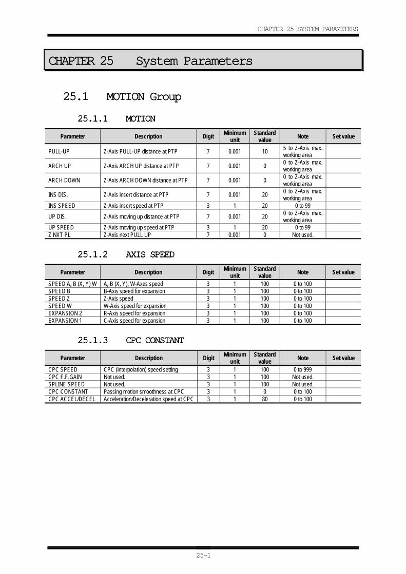
CHAPTER 25 SYSTEM PARAMETERS
25-1
CHAPTER 25CHAPTER 25CHAPTER 25CHAPTER 25 System ParametersSystem ParametersSystem ParametersSystem Parameters
25.125.125.125.1 MOTION GroupMOTION GroupMOTION GroupMOTION Group
25.1.125.1.125.1.125.1.1 MOTIONMOTIONMOTIONMOTION
Parameter Description Digit Minimumunit
Standardvalue Note Set value
PULL-UP Z-Axis PULL-UP distance at PTP 7 0.001 10 5 to Z-Axis max.working area
ARCH UP Z-Axis ARCH UP distance at PTP 7 0.001 0 0 to Z-Axis max.working area
ARCH DOWN Z-Axis ARCH DOWN distance at PTP 7 0.001 0 0 to Z-Axis max.working area
INS DIS. Z-Axis insert distance at PTP 7 0.001 20 0 to Z-Axis max.working area
INS SPEED Z-Axis insert speed at PTP 3 1 20 0 to 99
UP DIS. Z-Axis moving up distance at PTP 7 0.001 20 0 to Z-Axis max.working area
UP SPEED Z-Axis moving up speed at PTP 3 1 20 0 to 99Z NXT PL Z-Axis next PULL UP 7 0.001 0 Not used.
25.1.225.1.225.1.225.1.2 AXIS SPEEDAXIS SPEEDAXIS SPEEDAXIS SPEED
Parameter Description Digit Minimumunit
Standardvalue Note Set value
SPEED A, B (X, Y) W A, B (X, Y), W-Axes speed 3 1 100 0 to 100SPEED B B-Axis speed for expansion 3 1 100 0 to 100SPEED Z Z-Axis speed 3 1 100 0 to 100SPEED W W-Axis speed for expansion 3 1 100 0 to 100EXPANSION 2 R-Axis speed for expansion 3 1 100 0 to 100EXPANSION 1 C-Axis speed for expansion 3 1 100 0 to 100
25.1.325.1.325.1.325.1.3 CPC CONSTANTCPC CONSTANTCPC CONSTANTCPC CONSTANT
Parameter Description Digit Minimumunit
Standardvalue Note Set value
CPC SPEED CPC (interpolation) speed setting 3 1 100 0 to 999CPC F.F.GAIN Not used. 3 1 100 Not used.SPLINE SPEED Not used. 3 1 100 Not used.CPC CONSTANT Passing motion smoothness at CPC 3 1 0 0 to 100CPC ACCEL/DECEL Acceleration/Deceleration speed at CPC 3 1 80 0 to 100
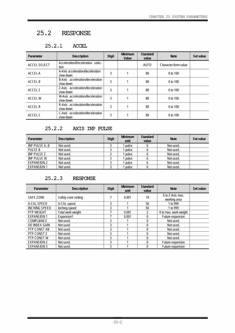
CHAPTER 25 SYSTEM PARAMETERS
25-2
25.225.225.225.2 RESPONSERESPONSERESPONSERESPONSE
25.2.125.2.125.2.125.2.1 ACCELACCELACCELACCEL
Parameter Description Digit MinimumValue
Standardvalue Note Set value
ACCEL SELECT Acceleration/Deceleration selec-tion AUTO Character-form value
ACCEL A A-Axis acceleration/decelerationslow down 3 1 80 0 to 100
ACCEL B B-Axis acceleration/decelerationslow down 3 1 80 0 to 100
ACCEL Z Z-Axis acceleration/decelerationslow down 3 1 80 0 to 100
ACCEL W W-Axis acceleration/decelerationslow down 3 1 80 0 to 100
ACCEL R R-Axis acceleration/decelerationslow down 3 1 80 0 to 100
ACCEL C C-Axis acceleration/decelerationslow down 3 1 80 0 to 100
25.2.225.2.225.2.225.2.2 AXIS INP PULSEAXIS INP PULSEAXIS INP PULSEAXIS INP PULSE
Parameter Description Digit Minimumunit
Standardvalue Note Set value
INP PULSE A, B Not used. 3 1 pulse 6 Not used.PULSE B Not used. 3 1 pulse 6 Not used.INP PULSE Z Not used. 3 1 pulse 6 Not used.INP PULSE W Not used. 3 1 pulse 6 Not used.EXPANSION 2 Not used. 3 1 pulse 6 Not used.EXPANSION 1 Not used. 3 1 pulse 6 Not used.
25.2.325.2.325.2.325.2.3 RESPONSERESPONSERESPONSERESPONSE
Parameter Description Digit Minimumunit
Standardvalue Note Set value
SAFE.ZONE Safety zone setting 7 0.001 10 0 to Z-Axis max.working area
A-CAL SPEED A-CAL speed 3 1 50 1 to 999INCHING SPEED Inching speed 3 1 50 1 to 999PTP WEIGHT Total work weight 7 0.001 2 0 to max. work weightEXPANSION 1 Expansion1 7 0.001 0 Future expansionCOMPLIANCE Not used. 3 1 0 Not used.DD INDEX GAIN Not used. 3 1 0 Not used.PTP CONST AB Not used. 3 1 0 Not used.PTP CONST Z Not used. 3 1 0 Not used.PTP CONST W Not used. 3 1 0 Not used.EXPANSION 2 Not used. 3 1 0 Future expansionEXPANSION 3 Not used. 3 1 0 Future expansion
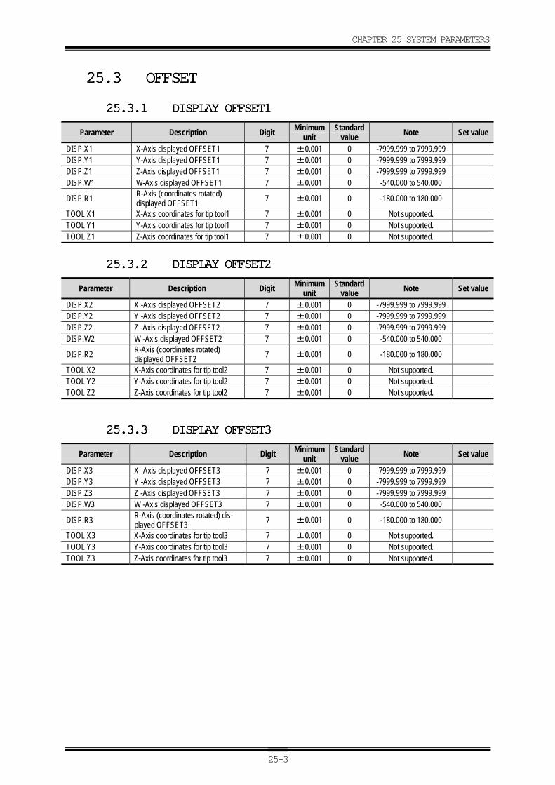
CHAPTER 25 SYSTEM PARAMETERS
25-3
25.325.325.325.3 OFFSETOFFSETOFFSETOFFSET
25.3.125.3.125.3.125.3.1 DISPLAY OFFSET1DISPLAY OFFSET1DISPLAY OFFSET1DISPLAY OFFSET1
Parameter Description Digit Minimumunit
Standardvalue Note Set value
DISP.X1 X-Axis displayed OFFSET1 7 ±0.001 0 -7999.999 to 7999.999DISP.Y1 Y-Axis displayed OFFSET1 7 ±0.001 0 -7999.999 to 7999.999DISP.Z1 Z-Axis displayed OFFSET1 7 ±0.001 0 -7999.999 to 7999.999DISP.W1 W-Axis displayed OFFSET1 7 ±0.001 0 -540.000 to 540.000
DISP.R1 R-Axis (coordinates rotated)displayed OFFSET1 7 ±0.001 0 -180.000 to 180.000
TOOL X1 X-Axis coordinates for tip tool1 7 ±0.001 0 Not supported.TOOL Y1 Y-Axis coordinates for tip tool1 7 ±0.001 0 Not supported.TOOL Z1 Z-Axis coordinates for tip tool1 7 ±0.001 0 Not supported.
25.3.225.3.225.3.225.3.2 DISPLAY OFFSET2DISPLAY OFFSET2DISPLAY OFFSET2DISPLAY OFFSET2
Parameter Description Digit Minimumunit
Standardvalue Note Set value
DISP.X2 X -Axis displayed OFFSET2 7 ±0.001 0 -7999.999 to 7999.999DISP.Y2 Y -Axis displayed OFFSET2 7 ±0.001 0 -7999.999 to 7999.999DISP.Z2 Z -Axis displayed OFFSET2 7 ±0.001 0 -7999.999 to 7999.999DISP.W2 W -Axis displayed OFFSET2 7 ±0.001 0 -540.000 to 540.000
DISP.R2 R-Axis (coordinates rotated)displayed OFFSET2 7 ±0.001 0 -180.000 to 180.000
TOOL X2 X-Axis coordinates for tip tool2 7 ±0.001 0 Not supported.TOOL Y2 Y-Axis coordinates for tip tool2 7 ±0.001 0 Not supported.TOOL Z2 Z-Axis coordinates for tip tool2 7 ±0.001 0 Not supported.
25.3.325.3.325.3.325.3.3 DISPLAY OFFSET3DISPLAY OFFSET3DISPLAY OFFSET3DISPLAY OFFSET3
Parameter Description Digit Minimumunit
Standardvalue Note Set value
DISP.X3 X -Axis displayed OFFSET3 7 ±0.001 0 -7999.999 to 7999.999DISP.Y3 Y -Axis displayed OFFSET3 7 ±0.001 0 -7999.999 to 7999.999DISP.Z3 Z -Axis displayed OFFSET3 7 ±0.001 0 -7999.999 to 7999.999DISP.W3 W -Axis displayed OFFSET3 7 ±0.001 0 -540.000 to 540.000
DISP.R3 R-Axis (coordinates rotated) dis-played OFFSET3 7 ±0.001 0 -180.000 to 180.000
TOOL X3 X-Axis coordinates for tip tool3 7 ±0.001 0 Not supported.TOOL Y3 Y-Axis coordinates for tip tool3 7 ±0.001 0 Not supported.TOOL Z3 Z-Axis coordinates for tip tool3 7 ±0.001 0 Not supported.
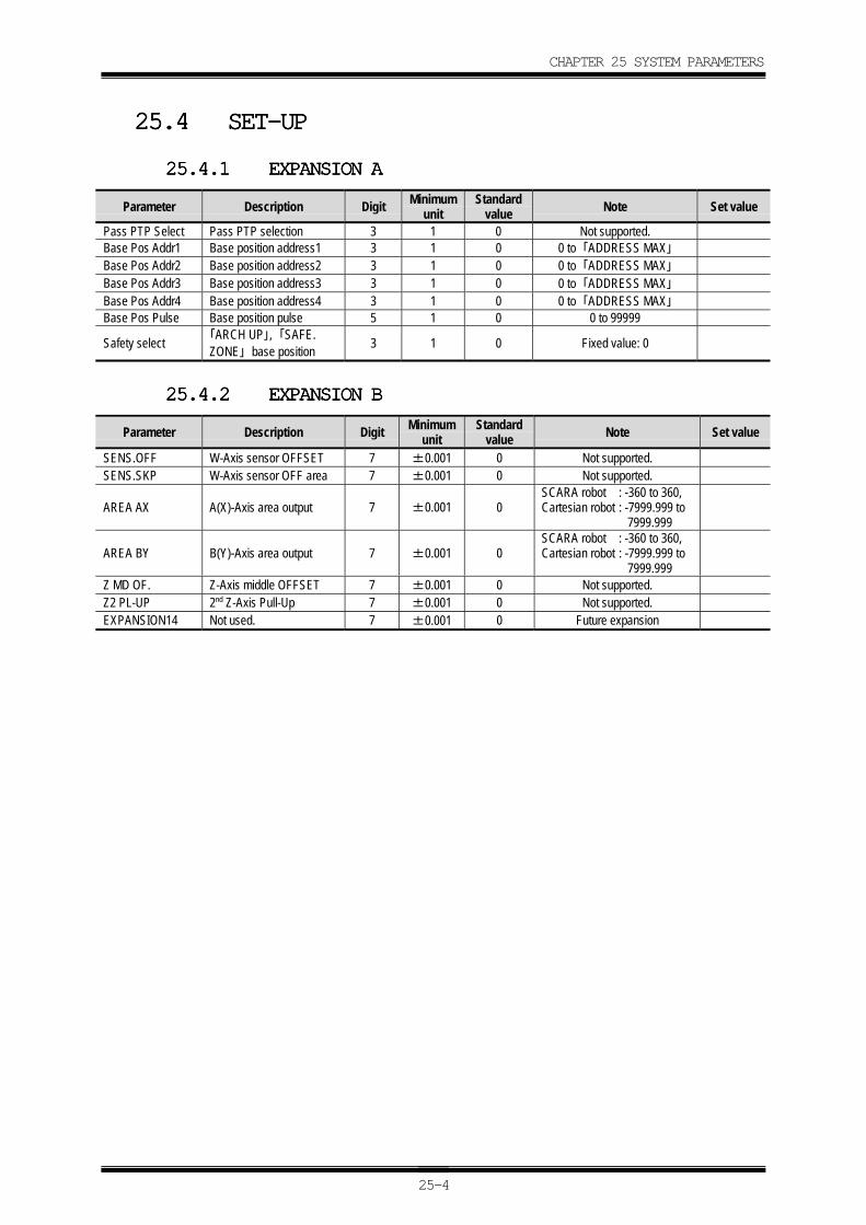
CHAPTER 25 SYSTEM PARAMETERS
25-4
25.425.425.425.4 SET-UPSET-UPSET-UPSET-UP
25.4.125.4.125.4.125.4.1 EXPANSION AEXPANSION AEXPANSION AEXPANSION A
Parameter Description Digit Minimumunit
Standardvalue Note Set value
Pass PTP Select Pass PTP selection 3 1 0 Not supported.Base Pos Addr1 Base position address1 3 1 0 0 to 「ADDRESS MAX」Base Pos Addr2 Base position address2 3 1 0 0 to 「ADDRESS MAX」Base Pos Addr3 Base position address3 3 1 0 0 to 「ADDRESS MAX」Base Pos Addr4 Base position address4 3 1 0 0 to 「ADDRESS MAX」Base Pos Pulse Base position pulse 5 1 0 0 to 99999
Safety select 「ARCH UP」, 「SAFE.ZONE」 base position 3 1 0 Fixed value: 0
25.4.225.4.225.4.225.4.2 EXPANSION BEXPANSION BEXPANSION BEXPANSION B
Parameter Description Digit Minimumunit
Standardvalue Note Set value
SENS.OFF W-Axis sensor OFFSET 7 ±0.001 0 Not supported.SENS.SKP W-Axis sensor OFF area 7 ±0.001 0 Not supported.
AREA AX A(X)-Axis area output 7 ±0.001 0SCARA robot : -360 to 360,Cartesian robot : -7999.999 to
7999.999
AREA BY B(Y)-Axis area output 7 ±0.001 0SCARA robot : -360 to 360,Cartesian robot : -7999.999 to
7999.999Z MD OF. Z-Axis middle OFFSET 7 ±0.001 0 Not supported.Z2 PL-UP 2nd Z-Axis Pull-Up 7 ±0.001 0 Not supported.EXPANSION14 Not used. 7 ±0.001 0 Future expansion
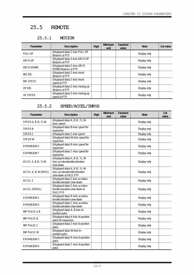
CHAPTER 25 SYSTEM PARAMETERS
25-5
25.525.525.525.5 REMOTEREMOTEREMOTEREMOTE
25.5.125.5.125.5.125.5.1 MOTIONMOTIONMOTIONMOTION
Parameter Description Digit Minimumunit
Standardvalue Note Set value
PULL-UP (Displayed data) Z-Axis PULL-UPdistance at PTP Display only
ARCH UP (Displayed data) Z-Axis ARCH UPdistance at PTP Display only
ARCH DOWN (Displayed data) Z-Axis ARCHDOWN distance at PTP Display only
INS DIS. (Displayed data) Z-Axis insertdistance at PTP Display only
INS SPEED (Displayed data) Z-Axis insertspeed at PTP Display only
UP DIS. (Displayed data) Z-Axis moving updistance at PTP Display only
UP SPEED (Displayed data) Z-Axis moving upspeed at PTP Display only
25.5.225.5.225.5.225.5.2 SPEED/ACCEL/INPOSSPEED/ACCEL/INPOSSPEED/ACCEL/INPOSSPEED/ACCEL/INPOS
Parameter Description Digit Minimumunit
Standardvalue Note Set
value
SPEED A, B (X, Y) W (Displayed data) A, B (X, Y), W-Axes speed Display only
SPEED B (Displayed data) B-Axis speed forexpansion Display only
SPEED Z (Displayed data) Z-Axis speed Display only
SPEED W (Displayed data) W-Axis speed forexpansion Display only
EXPANSION 2 (Displayed data) R-Axis speed forexpansion Display only
EXPANSION 1 (Displayed data) C-Axis speed forexpansion Display only
ACCEL A, B (X, Y) W(Displayed data) A, B (X, Y), W-Axis acceleration/decelerationslow down
Display only
ACCEL A, B, W (PASS)(Displayed data) A, B (X, Y), W-Axis acceleration/decelerationslow down at PASS PTP
Display only
ACCEL Z (Displayed data) Z-Axis accelera-tion/deceleration slow down Display only
ACCEL Z(PASS)(Displayed data) Z-Axis accelera-tion/deceleration slow down atPASS PTP
Display only
EXPANSION 3 (Displayed data) R-Axis accelera-tion/deceleration slow down Display only
EXPANSION 4 (Displayed data) C-Axis accelera-tion/deceleration slow down Display only
INP PULSE A B (Displayed data) A, B-Axis In-position pulse Display only
INP PULSE B (Displayed data) A-Axis In-positionpulse for expansion Display only
INP PULSE Z (Displayed data) Z-Axis In-positionpulse Display only
INP PULSE W (Displayed data) W-Axis In-position pulse Display only
EXPANSION 5 (Displayed data) R-Axis In-positionpulse Display only
EXPANSION 6 (Displayed data) C-Axis In-positionpulse Display only
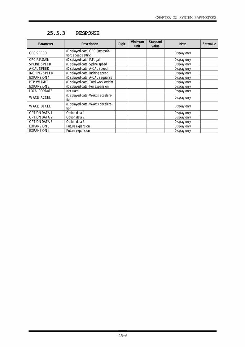
CHAPTER 25 SYSTEM PARAMETERS
25-6
25.5.325.5.325.5.325.5.3 RESPONSERESPONSERESPONSERESPONSE
Parameter Description Digit Minimumunit
Standardvalue Note Set value
CPC SPEED (Displayed data) CPC (interpola-tion) speed setting Display only
CPC F.F.GAIN (Displayed data) F.F. gain Display onlySPLINE SPEED (Displayed data) Spline speed Display onlyA-CAL SPEED (Displayed data) A-CAL speed Display onlyINCHING SPEED (Displayed data) Inching speed Display onlyEXPANSION 1 (Displayed data) A-CAL sequence Display onlyPTP WEIGHT (Displayed data) Total work weight Display onlyEXPANSION 2 (Displayed data) For expansion Display onlyLOCAL CODINATE Not used. Display only
W AXIS ACCEL (Displayed data) W-Axis accelera-tion Display only
W AXIS DECEL (Displayed data) W-Axis decelera-tion Display only
OPTION DATA 1 Option data 1 Display onlyOPTION DATA 2 Option data 2 Display onlyOPTION DATA 3 Option data 3 Display onlyEXPANSION 3 Future expansion Display onlyEXPANSION 4 Future expansion Display only
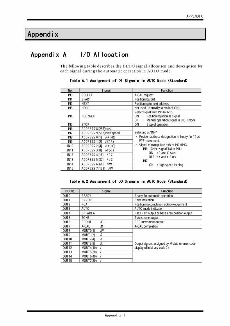
APPENDIX
Appendix-1
AppendixAppendixAppendixAppendix
Appendix AAppendix AAppendix AAppendix A I/O AllocationI/O AllocationI/O AllocationI/O Allocation
The following table describes the DI/DO signal allocation and description foreach signal during the automatic operation in AUTO mode.
Table A.Table A.Table A.Table A.1111 Assignment of DI Signals in AUTO Mode (Standard) Assignment of DI Signals in AUTO Mode (Standard) Assignment of DI Signals in AUTO Mode (Standard) Assignment of DI Signals in AUTO Mode (Standard)
No. Signal FunctionIN0 SELECT A-CAL requestIN1 START Positioning startIN2 NEXT Positioning to next addressIN3 HOLD Not used. (Normally servo lock ON)
IN4 POS/INCHSelect signal from IN6 to IN15ON : Positioning address signalOFF : Manual operation signal in INCH mode
IN5 STOP ON : Stop of operationIN6 ADDRESS 8 [256]/axisIN7 ADDRESS 9 [512]/high speedIN8 ADDRESS 0 [1] /+X(+R)IN9 ADDRESS 1 [2] /-X(-R)IN10 ADDRESS 2 [4] /+Y(+C)IN11 ADDRESS 3 [8] /-Y(-C)IN12 ADDRESS 4 [16] /↑ZIN13 ADDRESS 5 [32] /↓ZIN14 ADDRESS 6 [64] /+WIN15 ADDRESS 7 [128] /-W
Selecting at “IN4”・ Position address designation in binary (in [ ]) at
PTP movement.・ Signal to manipulate axis at INCHING.
IN6: Select signal IN8 to IN11ON : R and C-AxesOFF : X and Y-Axes
IN7ON : High-speed inching
Table A.Table A.Table A.Table A.2222 Assignment of DO Signals in AUTO Mode (Standard) Assignment of DO Signals in AUTO Mode (Standard) Assignment of DO Signals in AUTO Mode (Standard) Assignment of DO Signals in AUTO Mode (Standard)
DO No. Signal FunctionOUT0 READY Ready for automatic operationOUT1 ERROR Error indicationOUT2 PCA Positioning completion acknowledgementOUT3 AUTO AUTO mode indicationOUT4 BP・AREA Pass PTP output or base area position outputOUT5 ZONE Z-Axis zone outputOUT6 CPOUT /C CPC movement outputOUT7 A-CAL /R A-CAL completionOUT8 MOUT0(1) /WOUT9 MOUT1(2) /ZOUT10 MOUT2(4) /YOUT11 MOUT3(8) /XOUT12 MOUT4(10) /OUT13 MOUT5(20) /OUT14 MOUT6(40) /OUT15 MOUT7(80) /
Output signals assigned by M-data or error codedisplayed in binary code ( ).
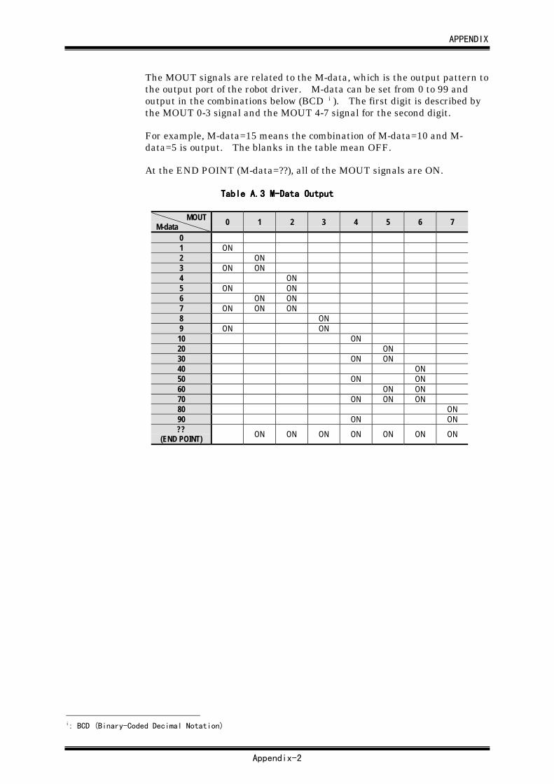
APPENDIX
Appendix-2
The MOUT signals are related to the M-data, which is the output pattern tothe output port of the robot driver. M-data can be set from 0 to 99 andoutput in the combinations below (BCD i ). The first digit is described bythe MOUT 0-3 signal and the MOUT 4-7 signal for the second digit.
For example, M-data=15 means the combination of M-data=10 and M-data=5 is output. The blanks in the table mean OFF.
At the END POINT (M-data=??), all of the MOUT signals are ON.
Table A.Table A.Table A.Table A.3333 M-Data Output M-Data Output M-Data Output M-Data Output
MOUTM-data 0 1 2 3 4 5 6 7
01 ON2 ON3 ON ON4 ON5 ON ON6 ON ON7 ON ON ON8 ON9 ON ON10 ON20 ON30 ON ON40 ON50 ON ON60 ON ON70 ON ON ON80 ON90 ON ON??
(END POINT) ON ON ON ON ON ON ON
i: BCD (Binary-Coded Decimal Notation)
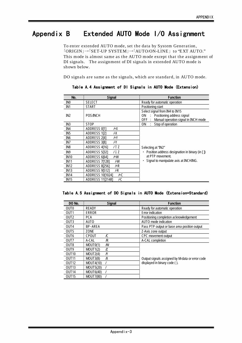
APPENDIX
Appendix-3
Appendix BAppendix BAppendix BAppendix B Extended AUTO Mode I/O AssignmentExtended AUTO Mode I/O AssignmentExtended AUTO Mode I/O AssignmentExtended AUTO Mode I/O Assignment
To enter extended AUTO mode, set the data by System Generation,「ORIGIN」→「SET-UP SYSTEM」→「AUTO/ON-LINE」 to “EXT AUTO.”This mode is almost same as the AUTO mode except that the assignment ofDI signals. The assignment of DI signals in extended AUTO mode isshown below.
DO signals are same as the signals, which are standard, in AUTO mode.
Table A.Table A.Table A.Table A.4444 Assignment of DI Signals in AUTO Mode (Extension) Assignment of DI Signals in AUTO Mode (Extension) Assignment of DI Signals in AUTO Mode (Extension) Assignment of DI Signals in AUTO Mode (Extension)
No. Signal FunctionIN0 SELECT Ready for automatic operationIN1 START Positioning start
IN2 POS/INCHSelect signal from IN4 to IN15ON : Positioning address signalOFF : Manual operation signal in INCH mode
IN3 STOP ON : Stop of operationIN4 ADDRESS 0[1] /+XIN5 ADDRESS 1[2] /-XIN6 ADDRESS 2[4] /+YIN7 ADDRESS 3[8] /-YIN8 ADDRESS 4[16] /↑ZIN9 ADDRESS 5[32] /↓ZIN10 ADDRESS 6[64] /+WIN11 ADDRESS 7[128] /-WIN12 ADDRESS 8[256] /+RIN13 ADDRESS 9[512] /-RIN14 ADDRESS 10[1024] /+CIN15 ADDRESS 11[2148] /-C
Selecting at “IN2”・ Position address designation in binary (in [ ])
at PTP movement.・ Signal to manipulate axis at INCHING.
Table A.Table A.Table A.Table A.5555 Assignment of DO Signals in AUTO Mode (Extension=Standard) Assignment of DO Signals in AUTO Mode (Extension=Standard) Assignment of DO Signals in AUTO Mode (Extension=Standard) Assignment of DO Signals in AUTO Mode (Extension=Standard)
DO No. Signal FunctionOUT0 READY Ready for automatic operationOUT1 ERROR Error indicationOUT2 PCA Positioning completion acknowledgementOUT3 AUTO AUTO mode indicationOUT4 BP・AREA Pass PTP output or base area position outputOUT5 ZONE Z-Axis zone outputOUT6 CPOUT /C CPC movement outputOUT7 A-CAL /R A-CAL completionOUT8 MOUT0(1) /WOUT9 MOUT1(2) /ZOUT10 MOUT2(4) /YOUT11 MOUT3(8) /XOUT12 MOUT4(10) /OUT13 MOUT5(20) /OUT14 MOUT6(40) /OUT15 MOUT7(80) /
Output signals assigned by M-data or error codedisplayed in binary code ( ).
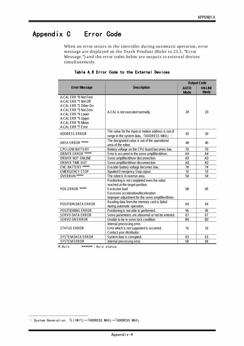
APPENDIX
Appendix-4
Appendix CAppendix CAppendix CAppendix C Error CodeError CodeError CodeError Code
When an error occurs in the controller during automatic operation, errormessage are displayed on the Teach Pendant (Refer to 23.3, “ErrorMessage.”) and the error codes below are outputs to external devicessimultaneously.
Table A.Table A.Table A.Table A.6666 Error Code to the External Devices Error Code to the External Devices Error Code to the External Devices Error Code to the External Devices
Output CodeError Message Description AUTO
ModeON-LINEMode
A-CAL ERR *0 Not FindA-CAL ERR *1 Not OffA-CAL ERR *2 Other OnA-CAL ERR *3 Not ZeroA-CAL ERR *4 LowerA-CAL ERR *5 UpperA-CAL ERR *6 MinusA-CAL ERR *7 Error
A-CAL is not executed normally. 2# 20
ADDRESS ERROR The value for the input or motion address is out ofrange in the system data, 「ADDRESS MAX」 i. 30 30
AREA ERROR ****** The designated value is out of the operationalarea of the robot. 4# 40
CPU LOW BATTERY Battery voltage on the CPU board becomes low. 70 70DRIVER ERROR ****** Error is occurred in the servo amplifier/driver. A# A#DRIVER NOT ONLINE Servo amplifier/driver disconnection A0 A0DRIVER TIME OUT Servo amplifier/driver disconnection A0 A0ENC BATTERY ****** Encoder battery voltage becomes low. 7# 7#EMERGENCY STOP Inputted Emergency Stop signal. 10 10OVERRUN ****** The robot is in overrun area. 5# 5#
POS.ERROR ******
Positioning is not completed even the robotreached at the target position.Excessive loadExcessive acceleration/decelerationImproper adjustment for the servo amplifier/driver.
0# 09
POSITION DATA ERROR Reading data from the memory card is failedduring automatic operation. 64 64
POSITIONING ERROR Positioning is not able to performed. 96 96SERVO DATA ERROR Servo parameters are abnormal or not be entered. 67 67SERVO ON ERROR Unable to be in servo lock condition B0 B0
STATUS ERRORInternal processing error.Error which is not supported is occurred.Contact your distributor.
16 16
SYSTEM DATA ERROR System data is corrupted. 63 63SYSTEM ERROR Internal processing error. 68 68
#:Axis ******:Axis status
i: System Generation, 「LIIMIT」→「ADDRESS MAX」→「ADDRESS MAX」
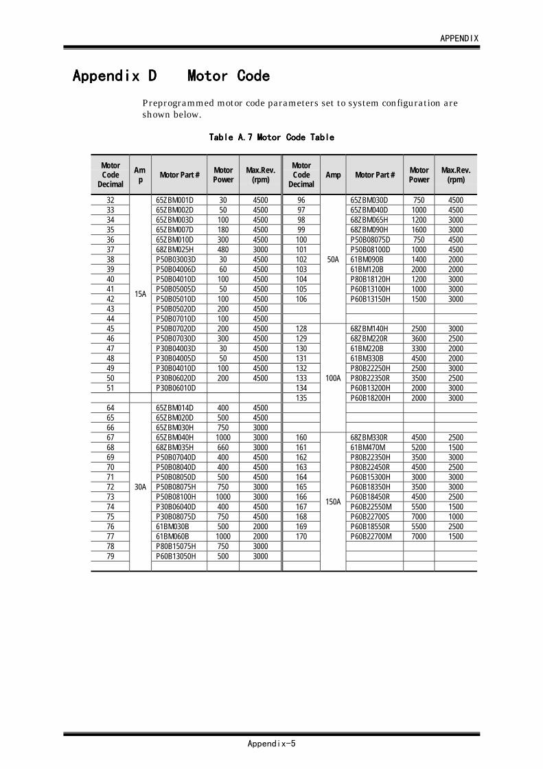
APPENDIX
Appendix-5
Appendix DAppendix DAppendix DAppendix D Motor CodeMotor CodeMotor CodeMotor Code
Preprogrammed motor code parameters set to system configuration areshown below.
Table A.Table A.Table A.Table A.7777 Motor Code Table Motor Code Table Motor Code Table Motor Code Table
MotorCode
DecimalAm
p Motor Part # MotorPower
Max.Rev.(rpm)
MotorCode
DecimalAmp Motor Part # Motor
PowerMax.Rev.
(rpm)
32 65ZBM001D 30 4500 96 65ZBM030D 750 450033 65ZBM002D 50 4500 97 65ZBM040D 1000 450034 65ZBM003D 100 4500 98 68ZBM065H 1200 300035 65ZBM007D 180 4500 99 68ZBM090H 1600 300036 65ZBM010D 300 4500 100 P50B08075D 750 450037 68ZBM025H 480 3000 101 P50B08100D 1000 450038 P50B03003D 30 4500 102 61BM090B 1400 200039 P50B04006D 60 4500 103 61BM120B 2000 200040 P50B04010D 100 4500 104 P80B18120H 1200 300041 P50B05005D 50 4500 105 P60B13100H 1000 300042 P50B05010D 100 4500 106 P60B13150H 1500 300043 P50B05020D 200 450044 P50B07010D 100 4500
50A
45 P50B07020D 200 4500 128 68ZBM140H 2500 300046 P50B07030D 300 4500 129 68ZBM220R 3600 250047 P30B04003D 30 4500 130 61BM220B 3300 200048 P30B04005D 50 4500 131 61BM330B 4500 200049 P30B04010D 100 4500 132 P80B22250H 2500 300050 P30B06020D 200 4500 133 P80B22350R 3500 250051
15A
P30B06010D 134 P60B13200H 2000 3000135 P60B18200H 2000 3000
64 65ZBM014D 400 450065 65ZBM020D 500 450066 65ZBM030H 750 3000
100A
67 65ZBM040H 1000 3000 160 68ZBM330R 4500 250068 68ZBM035H 660 3000 161 61BM470M 5200 150069 P50B07040D 400 4500 162 P80B22350H 3500 300070 P50B08040D 400 4500 163 P80B22450R 4500 250071 P50B08050D 500 4500 164 P60B15300H 3000 300072 P50B08075H 750 3000 165 P60B18350H 3500 300073 P50B08100H 1000 3000 166 P60B18450R 4500 250074 P30B06040D 400 4500 167 P60B22550M 5500 150075 P30B08075D 750 4500 168 P60B22700S 7000 100076 61BM030B 500 2000 169 P60B18550R 5500 250077 61BM060B 1000 2000 170 P60B22700M 7000 150078 P80B15075H 750 300079 P60B13050H 500 3000
30A
150A

APPENDIX
Appendix-6
Appendix EAppendix EAppendix EAppendix E Data Backup and Data LoadData Backup and Data LoadData Backup and Data LoadData Backup and Data Load
Table A.Table A.Table A.Table A.8888 Back Up and Data Load Back Up and Data Load Back Up and Data Load Back Up and Data Load
Data StoredLocation Backup Default Value Setting Data Load
System Data(System Generation,System Parameters)
RAM Memory card Refer to Chapter 21, “InitializingSystem Data.”
Download from thememory card.
Servo Parameters RAM Memory card Refer to Chapter 21, “InitializingSystem Data.”
Download from thememory card.
Position data RAM Memory card Refer to Chapter 22, “InitializingPosition Data.”
Download from thememory card.
Configuration EE-PROM None None Replace EE-PROM.