Embed Size (px)
Citation preview
Operation Manual
Dual 31-Band Graphic Equalizer
EQ-2231A
DUAL 31- BAND GRAPHIC EQUALIZER
WelcomeWelcomeA personal welcome to you from the management and employees of Inter-M
All of the co-workers here at Inter-M are dedicated to providing excellent products with inherently good value,and we are delighted you have purchased one of our products.
We sincerely trust this product will provide years of satisfactory service, but if anything is not to your completesatisfaction, we will endeavor to make things right.
Welcome to Inter-M, and thank you for becoming part of our worldwide extended family!
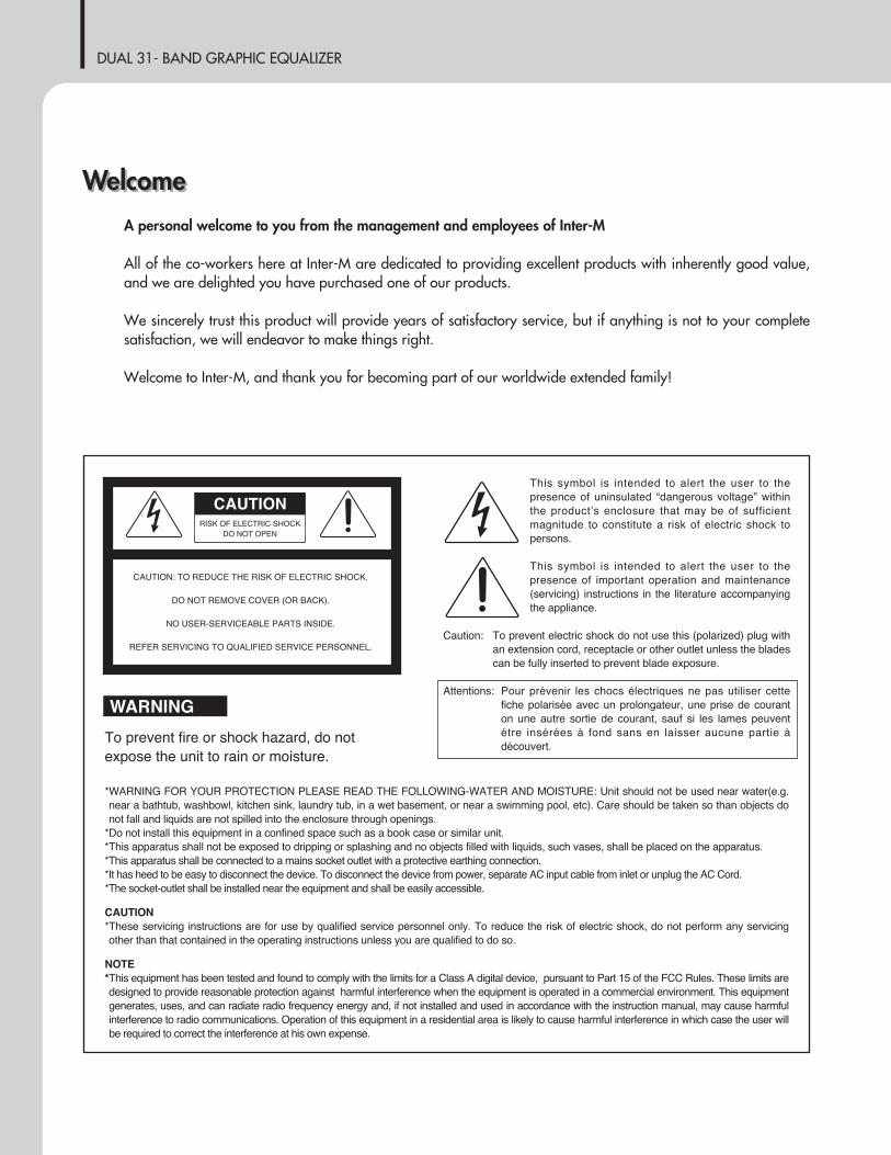
RISK OF ELECTRIC SHOCKDO NOT OPEN
CAUTION
CAUTION: TO REDUCE THE RISK OF ELECTRIC SHOCK.
DO NOT REMOVE COVER (OR BACK).
NO USER-SERVICEABLE PARTS INSIDE.
REFER SERVICING TO QUALIFIED SERVICE PERSONNEL.
WARNINGTo prevent fire or shock hazard, do notexpose the unit to rain or moisture.
*WARNING FOR YOUR PROTECTION PLEASE READ THE FOLLOWING-WATER AND MOISTURE: Unit should not be used near water(e.g.near a bathtub, washbowl, kitchen sink, laundry tub, in a wet basement, or near a swimming pool, etc). Care should be taken so than objects donot fall and liquids are not spilled into the enclosure through openings.
*Do not install this equipment in a confined space such as a book case or similar unit.*This apparatus shall not be exposed to dripping or splashing and no objects filled with liquids, such vases, shall be placed on the apparatus.*This apparatus shall be connected to a mains socket outlet with a protective earthing connection.*It has heed to be easy to disconnect the device. To disconnect the device from power, separate AC input cable from inlet or unplug the AC Cord.*The socket-outlet shall be installed near the equipment and shall be easily accessible.
CAUTION*These servicing instructions are for use by qualified service personnel only. To reduce the risk of electric shock, do not perform any servicingother than that contained in the operating instructions unless you are qualified to do so.
NOTE*This equipment has been tested and found to comply with the limits for a Class A digital device, pursuant to Part 15 of the FCC Rules. These limits aredesigned to provide reasonable protection against harmful interference when the equipment is operated in a commercial environment. This equipmentgenerates, uses, and can radiate radio frequency energy and, if not installed and used in accordance with the instruction manual, may cause harmfulinterference to radio communications. Operation of this equipment in a residential area is likely to cause harmful interference in which case the user willbe required to correct the interference at his own expense.
This symbol is intended to alert the user to thepresence of uninsulated “dangerous voltage” withinthe products enclosure that may be of sufficientmagnitude to constitute a risk of electric shock topersons.
This symbol is intended to alert the user to thepresence of important operation and maintenance(servicing) instructions in the literature accompanyingthe appliance.
Caution: To prevent electric shock do not use this (polarized) plug withan extension cord, receptacle or other outlet unless the bladescan be fully inserted to prevent blade exposure.
Attentions: Pour prévenir les chocs électriques ne pas utiliser cettefiche polarisée avec un prolongateur, une prise de couranton une autre sortie de courant, sauf si les lames peuventétre insérées à fond sans en laisser aucune partie àdécouvert.

DUAL 31- BAND GRAPHIC EQUALIZER
1EQ-2231A
ContentsContentsUnpacking .......................................................................................................................................2
InstallationEnvironment....................................................................................................................................2Important Safety Instructions.............................................................................................................2Short Form Instructions.....................................................................................................................3
Features............................................................................................................................................4Accessories.....................................................................................................................................4
Front Panel ......................................................................................................................................5
Rear Panel .......................................................................................................................................7
Applications ....................................................................................................................................8
Operation ........................................................................................................................................9Treating Feedback...........................................................................................................................9System Tuning...............................................................................................................................10
Troubleshooting ............................................................................................................................11Assistance.....................................................................................................................................11
Block Diagram ..............................................................................................................................12
Specifications ................................................................................................................................13
ServiceProcedures....................................................................................................................................15Schematic .....................................................................................................................................15Parts List .......................................................................................................................................15
Variations and Options ...............................................................................................................15
Warranty .......................................................................................................................................15

DUAL 31- BAND GRAPHIC EQUALIZER
2 EQ-2231A
Installation
UnpackingUnpackingAlthough your EQ-2231A is neither complicated nor difficult to operate, we recommend you take a few minutesto read this brief manual and familiarize yourself with the important information regarding product features,setup and operation.
As with most electronic devices, we strongly recommend you to retain the original packaging. In the unlikelyevent the product must be returned for servicing, the original packaging (or reasonable equivalent) is required.
InstallationEnvironmentNever place this product in an environment which could alter its performance or reduce its service life. Suchenvironments usually include high levels of heat, dust, moisture, and vibration.
IMPORTANT SAFETY INSTRUCTIONS1. Read these instructions.2. Keep these instructions.3. Heed all warnings.4. Follow all instructions.5. Do not use this apparatus near water.6. Clean only with dry cloth.7. Do not block any ventilation openings. Install in accordance with the manufacturer’s instructions.8. Do not install near any heat sources such as radiators, heat registers, stoves, or other apparatus (including
amplifiers) that produce heat.9. Do not defeat the safety purpose of the polarized or grounding-type plug. A polarized plug has two blades
with one wider than the other. A grounding type plug has two blades and a third grounding prong. The wideblade or the third prong are provided for your safety. If the provided plug does not fit into your outlet, consultan electrician for replacement of the obsolete outlet.
10. Protect the power cord from being walked on or pinched particularly at plugs, convenience receptacles, andthe point where they exit from the apparatus.
11. Only use attachments/accessories specified by the manufacturer.12. Use only with the cart, stand, tripod, bracket, or table specified by the manufacturer, or sold with the apparatus.
When a cart is used, use caution when moving the cart/apparatus combination to avoid injury from tip-over.13. Unplug this apparatus during lightning storms or when unused for long periods of time.14. Refer all servicing to qualified service personnel. Servicing is required when the
apparatus has been damaged in any way, such as power-supply cord or plug isdamaged, liquid has been spilled or objects have fallen into the apparatus, theapparatus has been exposed to rain or moisture, does not operate normally, or hasbeen dropped.
S3125A
S3125A
DUAL 31- BAND GRAPHIC EQUALIZER
3EQ-2231A
Short Form Instructions1. Prior to connecting the AC or DC power, adjust the LEVEL slider control to the fully attenuated position (all
the way down).
2. All other sliders should be set to the “0” or center position.
3. The BYPASS switch should be in the OFF position.
4. Connect an appropriate line level input signal to either the balanced XLR or the balanced Euroblockconnector marked INPUTS.
5. Connect the OUTPUTS using either the balanced XLR or the balanced Euroblock connector to anappropriate device.
6. With the power switch in the OFF position, plug in the supplied Universal AC power cord to the productand an appropriate AC source.
7. Depress the power switch to the ON position. The power indicator will illuminate.
8. The product is ready for operation. Slowly increase the LEVEL slider to the desired operating level withoutexceeding “0”, then make other adjustments as necessary.
9. Operate the product and the system in a manner which DOES NOT illuminate the PEAK warning indicator.
DUAL 31- BAND GRAPHIC EQUALIZER
4 EQ-2231A
FeaturesFeatures- Dual channel, 31 band graphic equalizer.- Constant Q (Constant Bandwidth) filter design.- Long throw (45mm) slider controls.- Balanced XLR and balanced Euroblock input and output connectors.- Selectable adjustment range of ±6dB or ±12dB.- Signal Bypass switch allows for a quick assessment of the effect of the equalizer’s settings.- Peak warning indicator (active 6dB below peak).- Selectable, Cut Only or Boost/Cut, operation.- Selectable 80Hz high pass filter to reduce frequency response below 80Hz.- Rack Ears for permanent installation in a standard 19” (rack mount width) enclosure.- Detachable AC power cord.- DC 24V power input.
AccessoriesOne detachable AC power cord and EURO BLOCKS are provided for use with this product.
DUAL 31- BAND GRAPHIC EQUALIZER
5EQ-2231A
Front PanelFront Panel
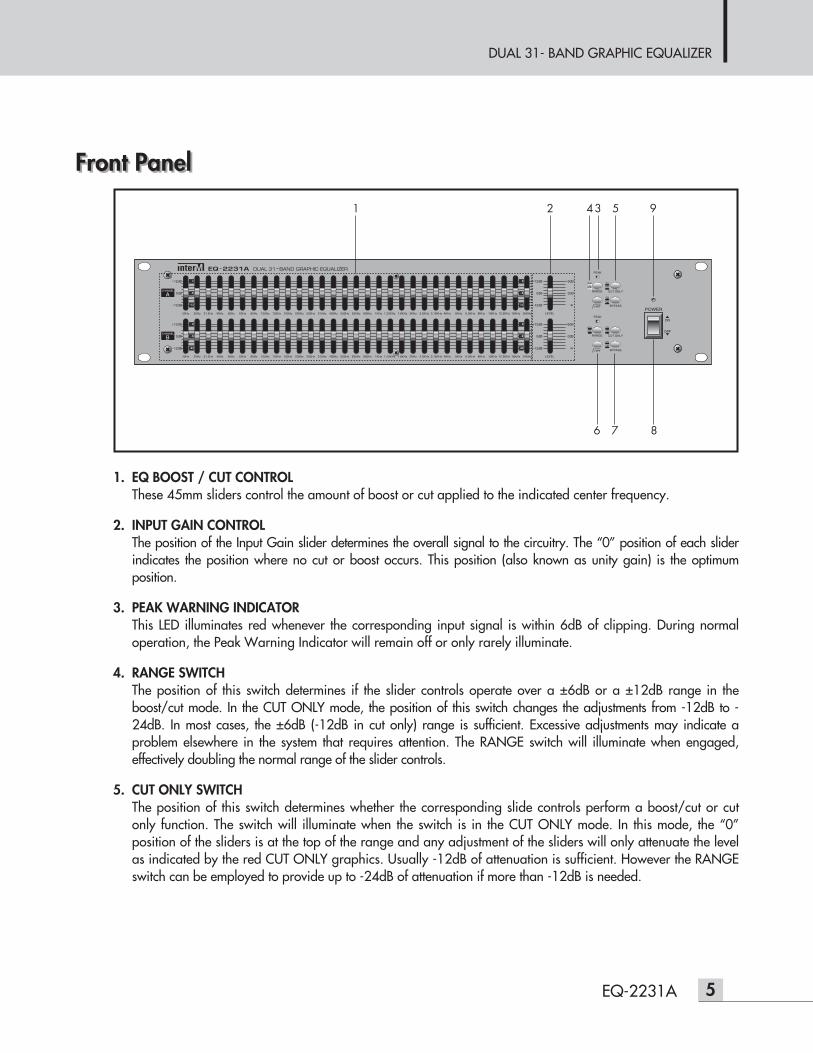
1. EQ BOOST / CUT CONTROLThese 45mm sliders control the amount of boost or cut applied to the indicated center frequency.
2. INPUT GAIN CONTROLThe position of the Input Gain slider determines the overall signal to the circuitry. The “0” position of each sliderindicates the position where no cut or boost occurs. This position (also known as unity gain) is the optimumposition.
3. PEAK WARNING INDICATORThis LED illuminates red whenever the corresponding input signal is within 6dB of clipping. During normaloperation, the Peak Warning Indicator will remain off or only rarely illuminate.
4. RANGE SWITCHThe position of this switch determines if the slider controls operate over a ±6dB or a ±12dB range in theboost/cut mode. In the CUT ONLY mode, the position of this switch changes the adjustments from -12dB to -24dB. In most cases, the ±6dB (-12dB in cut only) range is sufficient. Excessive adjustments may indicate aproblem elsewhere in the system that requires attention. The RANGE switch will illuminate when engaged,effectively doubling the normal range of the slider controls.
5. CUT ONLY SWITCHThe position of this switch determines whether the corresponding slide controls perform a boost/cut or cutonly function. The switch will illuminate when the switch is in the CUT ONLY mode. In this mode, the “0”position of the sliders is at the top of the range and any adjustment of the sliders will only attenuate the levelas indicated by the red CUT ONLY graphics. Usually -12dB of attenuation is sufficient. However the RANGEswitch can be employed to provide up to -24dB of attenuation if more than -12dB is needed.
1 2 34 5
6 7 8
9
DUAL 31- BAND GRAPHIC EQUALIZER
6 EQ-2231A
6. HIGH PASS FILTERThe position of this switch determines if the 80Hz High Pass Filter is applied to the signal. The switch will illuminatewhen the High Pass Filter is engaged. This feature is effective at removing rumble or other low frequencyinformation (below 80Hz) which may be undesirable.
7. BYPASS SWITCHThe position of this switch determines whether the product operates normally or allows the signal to bypassall equalization settings and pass through unaffected. The switch will illuminate when it is in the BYPASSmode. In the event of a loss of power, the product will default to BYPASS mode allowing the signal to pass.
8. POWER SWITCHThe position of this switch determines whether the power is ON or OFF. In the OFF position, the input(s) arehard bypassed to the output(s) to allow the signal to pass through unaffected as it does in BYPASS.
9. POWER INDICATORDisplay the power ON/OFF.
DUAL 31- BAND GRAPHIC EQUALIZER
7EQ-2231A
Rear PanelRear Panel
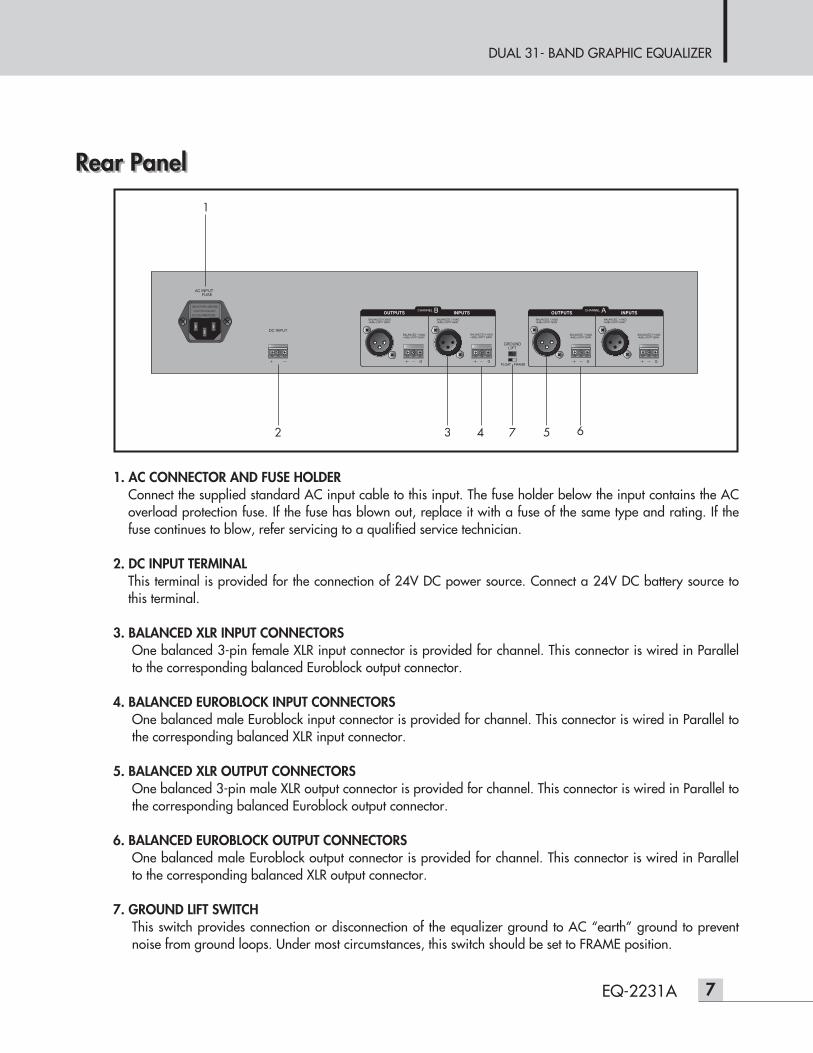
1. AC CONNECTOR AND FUSE HOLDERConnect the supplied standard AC input cable to this input. The fuse holder below the input contains the ACoverload protection fuse. If the fuse has blown out, replace it with a fuse of the same type and rating. If thefuse continues to blow, refer servicing to a qualified service technician.
2. DC INPUT TERMINALThis terminal is provided for the connection of 24V DC power source. Connect a 24V DC battery source tothis terminal.
3. BALANCED XLR INPUT CONNECTORSOne balanced 3-pin female XLR input connector is provided for channel. This connector is wired in Parallelto the corresponding balanced Euroblock output connector.
4. BALANCED EUROBLOCK INPUT CONNECTORSOne balanced male Euroblock input connector is provided for channel. This connector is wired in Parallel tothe corresponding balanced XLR input connector.
5. BALANCED XLR OUTPUT CONNECTORSOne balanced 3-pin male XLR output connector is provided for channel. This connector is wired in Parallel tothe corresponding balanced Euroblock output connector.
6. BALANCED EUROBLOCK OUTPUT CONNECTORSOne balanced male Euroblock output connector is provided for channel. This connector is wired in Parallelto the corresponding balanced XLR output connector.
7. GROUND LIFT SWITCHThis switch provides connection or disconnection of the equalizer ground to AC “earth” ground to preventnoise from ground loops. Under most circumstances, this switch should be set to FRAME position.
1
2 3 4 5 67
DUAL 31- BAND GRAPHIC EQUALIZER
8 EQ-2231A
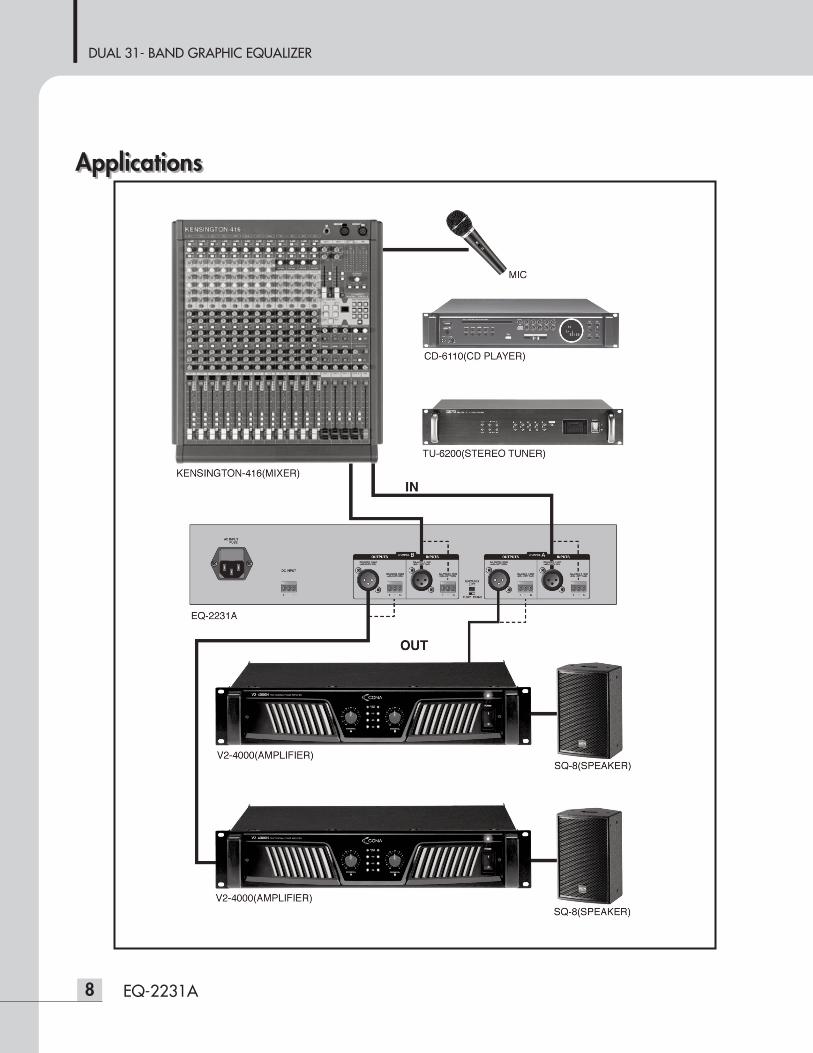
ApplicationsApplications
DUAL 31- BAND GRAPHIC EQUALIZER
9EQ-2231A
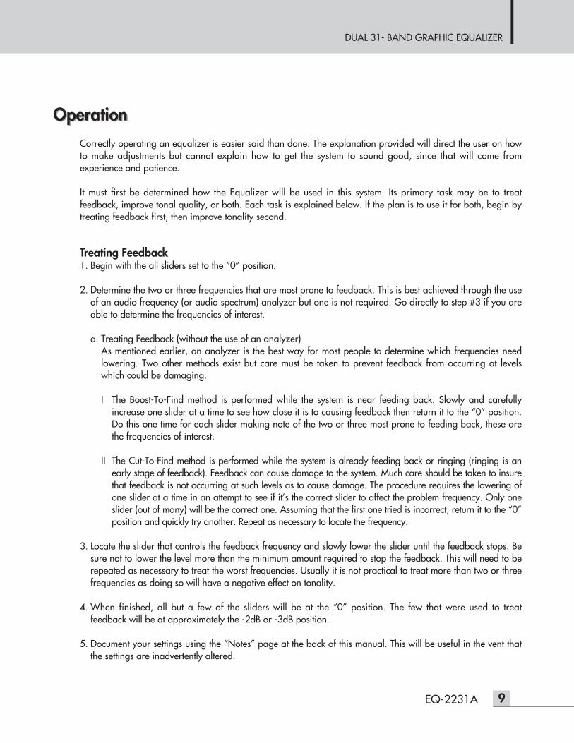
OperationOperationCorrectly operating an equalizer is easier said than done. The explanation provided will direct the user on howto make adjustments but cannot explain how to get the system to sound good, since that will come fromexperience and patience.
It must first be determined how the Equalizer will be used in this system. Its primary task may be to treatfeedback, improve tonal quality, or both. Each task is explained below. If the plan is to use it for both, begin bytreating feedback first, then improve tonality second.
Treating Feedback1. Begin with the all sliders set to the “0” position.
2. Determine the two or three frequencies that are most prone to feedback. This is best achieved through the useof an audio frequency (or audio spectrum) analyzer but one is not required. Go directly to step #3 if you areable to determine the frequencies of interest.
a. Treating Feedback (without the use of an analyzer)As mentioned earlier, an analyzer is the best way for most people to determine which frequencies needlowering. Two other methods exist but care must be taken to prevent feedback from occurring at levelswhich could be damaging.
I The Boost-To-Find method is performed while the system is near feeding back. Slowly and carefullyincrease one slider at a time to see how close it is to causing feedback then return it to the “0” position.Do this one time for each slider making note of the two or three most prone to feeding back, these arethe frequencies of interest.
II The Cut-To-Find method is performed while the system is already feeding back or ringing (ringing is anearly stage of feedback). Feedback can cause damage to the system. Much care should be taken to insurethat feedback is not occurring at such levels as to cause damage. The procedure requires the lowering ofone slider at a time in an attempt to see if it’s the correct slider to affect the problem frequency. Only oneslider (out of many) will be the correct one. Assuming that the first one tried is incorrect, return it to the “0”position and quickly try another. Repeat as necessary to locate the frequency.
3. Locate the slider that controls the feedback frequency and slowly lower the slider until the feedback stops. Besure not to lower the level more than the minimum amount required to stop the feedback. This will need to berepeated as necessary to treat the worst frequencies. Usually it is not practical to treat more than two or threefrequencies as doing so will have a negative effect on tonality.
4. When finished, all but a few of the sliders will be at the “0” position. The few that were used to treatfeedback will be at approximately the -2dB or -3dB position.
5. Document your settings using the “Notes” page at the back of this manual. This will be useful in the vent thatthe settings are inadvertently altered.
DUAL 31- BAND GRAPHIC EQUALIZER
10 EQ-2231A
System Tuning1. Begin with the all sliders set to the “0” position unless adjustments have been made to treat feedback.
2. Have a Plan. Identify what improvements the system needs and which of those are capable of beingaddressed through equalization. System design, not equalization, determines the general parameters ofsystem performance. Do not attempt to counteract design shortfalls with an equalizer. An equalizer is theperfect tool for making frequency specific adjustments which improve overall system performance.
3. Make the necessary adjustments remembering two important items.a. Proper equalization is achieved with minimal equalization.b. Better to cut than to boost. Cut excessive frequencies rather than boost weak frequencies.
4. Document your settings.

DUAL 31- BAND GRAPHIC EQUALIZER
11EQ-2231A
TroubleshootingTroubleshooting
AssistanceThis section assumes that the product functions properly and that one or more product features or functions havebeen engaged, defeated, or not properly adjusted.
Begin troubleshooting by taking a moment to review the “Short Form Instructions” portion of this manual. It mayhelp to identify a feature that has been overlooked and related to the problem.
Symptom:None of the frequency related slide controls have any affect.Probable cause#1: The BYPASS switch is engaged, confirmed by illumination.Probable cause#2: Loss of power, either the POWER switch is in the OFF position, or the product is not
connected to an AC or DC source. The POWER LED will illuminate when the POWER switchis in the ON position and AC or DC power is available.
Symptom:The frequency related slide controls below 80Hz have little or no affect.Probable cause: The HPF has been engaged as confirmed by the illuminated corresponding LED.
Symptom:Low output even with reasonable settings (approximately “0”)Probable cause#1: The CUT ONLY switch is engaged as confirmed by the corresponding LED. With the CUT
ONLY switch engaged the red graphics are used and indicate that the 0 position (unity) hasmoved from the middle to the top of the slider. The RANGE switch will magnify this effect if itis engaged as confirmed by the corresponding LED.
Probable cause#2: Incompatible signal to or from other devices in the system.
Symptom:Distorted sound and/or the PEAK LED is illuminated.Probable cause#1: Too much boost because the RANGE switch is doubling the amount of boost.Probable cause#2: Too much boost is occurring due the position of the sliders (above “0”).Probable cause#3: Incorrect or overdriven input signal being received from another product. Be sure that this
product is only receiving one input signal per channel, XLR or euroblock, not both.
DUAL 31- BAND GRAPHIC EQUALIZER
12 EQ-2231A
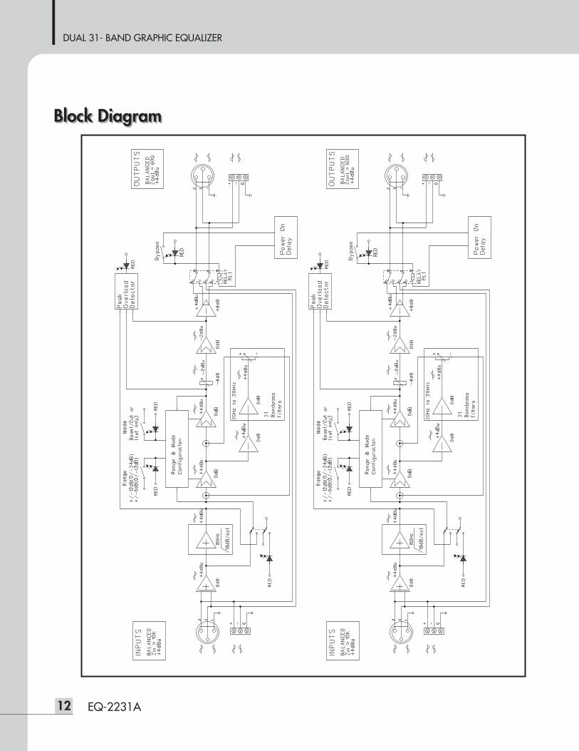
Block DiagramBlock Diagram
DUAL 31- BAND GRAPHIC EQUALIZER
13EQ-2231A
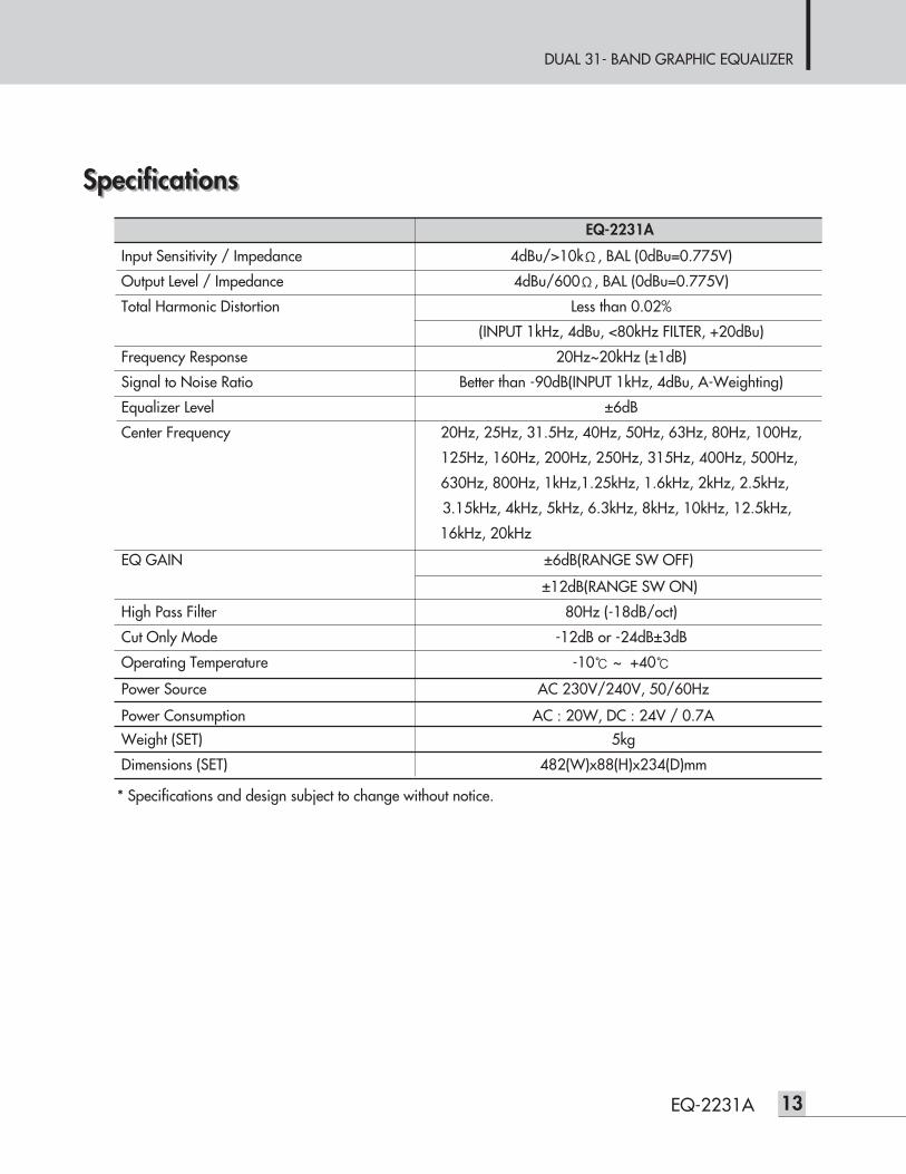
Input Sensitivity / Impedance 4dBu/>10kΩ, BAL (0dBu=0.775V)
Output Level / Impedance 4dBu/600Ω, BAL (0dBu=0.775V)
Total Harmonic Distortion Less than 0.02%
(INPUT 1kHz, 4dBu, <80kHz FILTER, +20dBu)
Frequency Response 20Hz~20kHz (±1dB)
Signal to Noise Ratio Better than -90dB(INPUT 1kHz, 4dBu, A-Weighting)
Equalizer Level ±6dB
Center Frequency 20Hz, 25Hz, 31.5Hz, 40Hz, 50Hz, 63Hz, 80Hz, 100Hz,
125Hz, 160Hz, 200Hz, 250Hz, 315Hz, 400Hz, 500Hz,
630Hz, 800Hz, 1kHz,1.25kHz, 1.6kHz, 2kHz, 2.5kHz,
3.15kHz, 4kHz, 5kHz, 6.3kHz, 8kHz, 10kHz, 12.5kHz,
16kHz, 20kHz
EQ GAIN ±6dB(RANGE SW OFF)
±12dB(RANGE SW ON)
High Pass Filter 80Hz (-18dB/oct)
Cut Only Mode -12dB or -24dB±3dB
Operating Temperature -10℃ ~ +40℃
Power Source AC 230V/240V, 50/60Hz
Power Consumption AC : 20W, DC : 24V / 0.7AWeight (SET) 5kg
Dimensions (SET) 482(W)x88(H)x234(D)mm
* Specifications and design subject to change without notice.
SpecificationsSpecifications
EQ-2231A
DUAL 31- BAND GRAPHIC EQUALIZER
14 EQ-2231A
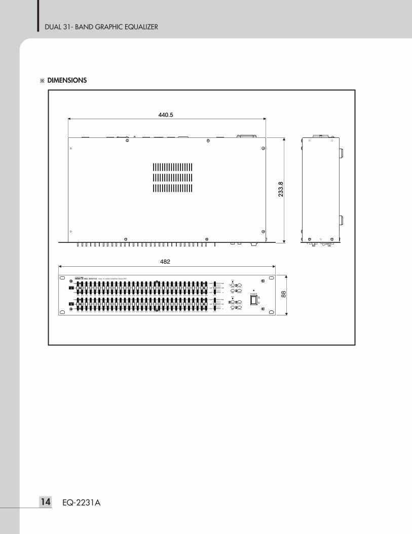
※ DIMENSIONS
440.5
DUAL 31- BAND GRAPHIC EQUALIZER
15EQ-2231A
ServiceService
ProceduresTake steps to insure the problem is not related to operator error or other products within the system. Informationprovided in the troubleshooting portion of this manual may help with this process. Once it is certain that theproblem is related to the product contact your warranty provider as described in the warranty section of thismanual.
SchematicA Schematic is available by contacting your warranty provider.
Parts ListA Parts List is available by contacting your warranty provider.
Variations and OptionsVariations and Options
VariationsProducts supplied through legitimate sources are compatible with local AC power requirements.
Options No optional items are available for this product.
WarrantyWarranty
Warranty terms and conditions vary by country and may not be the same for all products. Terms and conditionsof warranty for a given product may be determined first by locating the appropriate country which the productwas purchased in, then by locating the product type.
To obtain specific warranty information and available service locations contact Inter-M directly or the authorizedInter-M Distributor for your specific country or region.

NOTE

MADE IN KOREAJuly 2012 131168
Inter-M, Ltd. (Korea) began operations in 1983.
Since then, Inter-M has grown to become one of the largest manufacturers of professional audio and commercial sound electronics equipment in the world.
Inter-M has gained worldwide recognition for its own branded products, as well as private label manufacturing of electronics sold under other names (OEM).
The company is no longer just a Korean company, but rather a global company that is truly international in scope, with factories and offices in Korea and China, and sales and marketing operations located in Japan, Europe, and the U.S.A.
With more than 850 employees around the globe,Inter-M is well-poised for further growth and expansion.
Inter-M Americas, INC. 13875 Artesia Blvd. Cerritos, CA 90703 USATEL : +1-562-921-0313, FAX : +1-562-921-0370Home Page : http://www.inter-m.net, E-mail : [email protected]
Inter-M CorporationSeoul OFFICE:653-5 BANGHAK-DONG, DOBONG-KU, SEOUL, KOREA TEL : +82-2-2289-8140~8, FAX : +82-2-2289-8149Home Page : http://www.inter-m.com, E-mail : [email protected]