Embed Size (px)
Citation preview
Installation2 HDLink Pro DVI Digital2 HDLink Pro 3D DisplayPort2Contents
HDLink Operation Manual
How to Install
Installation 5 Installing and Uninstalling on Mac OS X 5 Installing and Uninstalling on Windows 5
Software
Using HDLink Utility 7
Lookup Tables (LUTs) 8 How to use Lookup Tables in HDLink 8 Importing and exporting 3D LUTs 9 Importing and exporting 1D LUTs 9
Settings 10
HDLink Models
HDLink Pro DVI Digital 13 Connection Diagrams 15
HDLink Pro 3D DisplayPort 16 Connection Diagrams 18 3D Connection Diagrams 19
HDLink Optical Fiber 21 Connection Diagrams 23
04
12
06
Helpful Information
Troubleshooting 25
Support 28
Developer Information
Blackmagic 2K Format 30 Overview 30 Vertical Timing Reference 31 Data Stream Format 32
Previous HDLink models
Using HDLink Utility 34
Lookup Tables (LUTs) 35
Settings 36
HDLink and HDLink 2 37
Connection Diagrams 39
Troubleshooting 40
3 Year Limited Warranty
Warranty Terms and Conditions 45
33
44
29
24
Welcome3
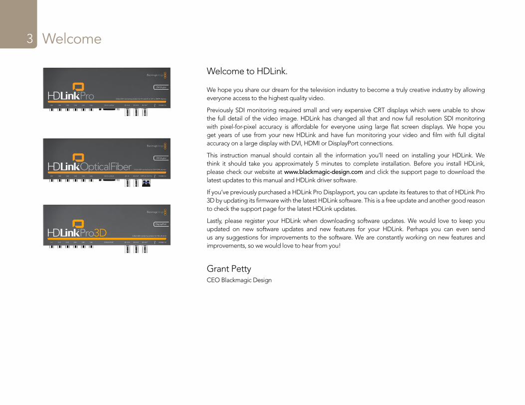
Welcome to HDLink.
We hope you share our dream for the television industry to become a truly creative industry by allowing everyone access to the highest quality video.
Previously SDI monitoring required small and very expensive CRT displays which were unable to show the full detail of the video image. HDLink has changed all that and now full resolution SDI monitoring with pixel-for-pixel accuracy is affordable for everyone using large flat screen displays. We hope you get years of use from your new HDLink and have fun monitoring your video and film with full digital accuracy on a large display with DVI, HDMI or DisplayPort connections.
This instruction manual should contain all the information you’ll need on installing your HDLink. We think it should take you approximately 5 minutes to complete installation. Before you install HDLink, please check our website at www.blackmagic-design.com and click the support page to download the latest updates to this manual and HDLink driver software.
If you’ve previously purchased a HDLink Pro Displayport, you can update its features to that of HDLink Pro 3D by updating its firmware with the latest HDLink software. This is a free update and another good reason to check the support page for the latest HDLink updates.
Lastly, please register your HDLink when downloading software updates. We would love to keep you updated on new software updates and new features for your HDLink. Perhaps you can even send us any suggestions for improvements to the software. We are constantly working on new features and improvements, so we would love to hear from you!
Grant PettyCEO Blackmagic Design
How to Install
4
Installation5
HDLink Utility enables you to update your HDLink with the latest firmware. Firmware updates may add new features, support new formats and standards, or provide increased compatibility with other video and audio hardware. It is always best to use the latest version of HDLink Utility so you receive all the latest updates for your HDLink.
The latest version of HDLink Utility can always be downloaded from www.blackmagic-design.com/support/software/.
HDLink Utility runs on the latest Leopard and Snow Leopard versions of Mac OS X. On the Windows platform, HDLink Utility runs on both 32 and 64-bit versions of Windows XP, Windows Vista and Windows 7 with the latest service packs installed. Testing on earlier versions of these operating systems is not conducted so it is always best to keep up to date with the latest versions of Mac OS X, Windows XP and Windows Vista.
Installing and Uninstalling on Mac OS XAfter downloading the latest HDLink software and unzipping the downloaded file, open the resulting HDLink Installer disk image to reveal its contents.
Launch the HDLink Installer and follow the on screen instructions. Restart your Mac when prompted. HDLink is now installed.
To uninstall HDLink from your Mac, open the HDLink Installer disk image and launch the Uninstall HDLink utility. Follow the on screen instructions to remove the software.
Installing and Uninstalling on WindowsAfter downloading the latest HDLink software and unzipping the downloaded file, you should see an HDLink folder containing this PDF manual and the HDLink installer.
Double-click the installer and follow the on screen prompts to complete the installation. When the installation has finished, it will prompt you to restart the computer. The restart will load a USB driver for HDLink Utility so that it can communicate with any HDLink model. Click “Restart” to complete the installation process. Once the computer has restarted, HDLink Utility will be fully installed and ready to use.
To uninstall HDLink from Windows XP, go to the Add or Remove Programs control panel, select Blackmagic HDLink and click on “Remove”.
To uninstall HDLink from Windows Vista or Windows 7, go to the Programs and Features control panel, select Blackmagic HDLink and click on “Uninstall”.

Software
6
Installation7 Using HDLink Utility7
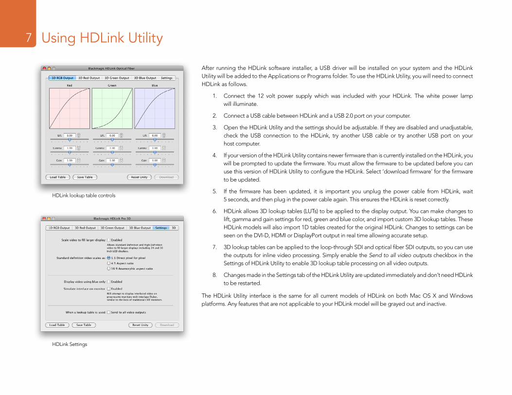
After running the HDLink software installer, a USB driver will be installed on your system and the HDLink Utility will be added to the Applications or Programs folder. To use the HDLink Utility, you will need to connect HDLink as follows.
1. Connect the 12 volt power supply which was included with your HDLink. The white power lamp will illuminate.
2. Connect a USB cable between HDLink and a USB 2.0 port on your computer.
3. Open the HDLink Utility and the settings should be adjustable. If they are disabled and unadjustable, check the USB connection to the HDLink, try another USB cable or try another USB port on your host computer.
4. If your version of the HDLink Utility contains newer firmware than is currently installed on the HDLink, you will be prompted to update the firmware. You must allow the firmware to be updated before you can use this version of HDLink Utility to configure the HDLink. Select ‘download firmware’ for the firmware to be updated.
5. If the firmware has been updated, it is important you unplug the power cable from HDLink, wait 5 seconds, and then plug in the power cable again. This ensures the HDLink is reset correctly.
6. HDLink allows 3D lookup tables (LUTs) to be applied to the display output. You can make changes to lift, gamma and gain settings for red, green and blue color, and import custom 3D lookup tables. These HDLink models will also import 1D tables created for the original HDLink. Changes to settings can be seen on the DVI-D, HDMI or DisplayPort output in real time allowing accurate setup.
7. 3D lookup tables can be applied to the loop-through SDI and optical fiber SDI outputs, so you can use the outputs for inline video processing. Simply enable the Send to all video outputs checkbox in the Settings of HDLink Utility to enable 3D lookup table processing on all video outputs.
8. Changes made in the Settings tab of the HDLink Utility are updated immediately and don’t need HDLink to be restarted.
The HDLink Utility interface is the same for all current models of HDLink on both Mac OS X and Windows platforms. Any features that are not applicable to your HDLink model will be grayed out and inactive.
HDLink lookup table controls
HDLink Settings
Installation8 Lookup Tables (LUTs)8
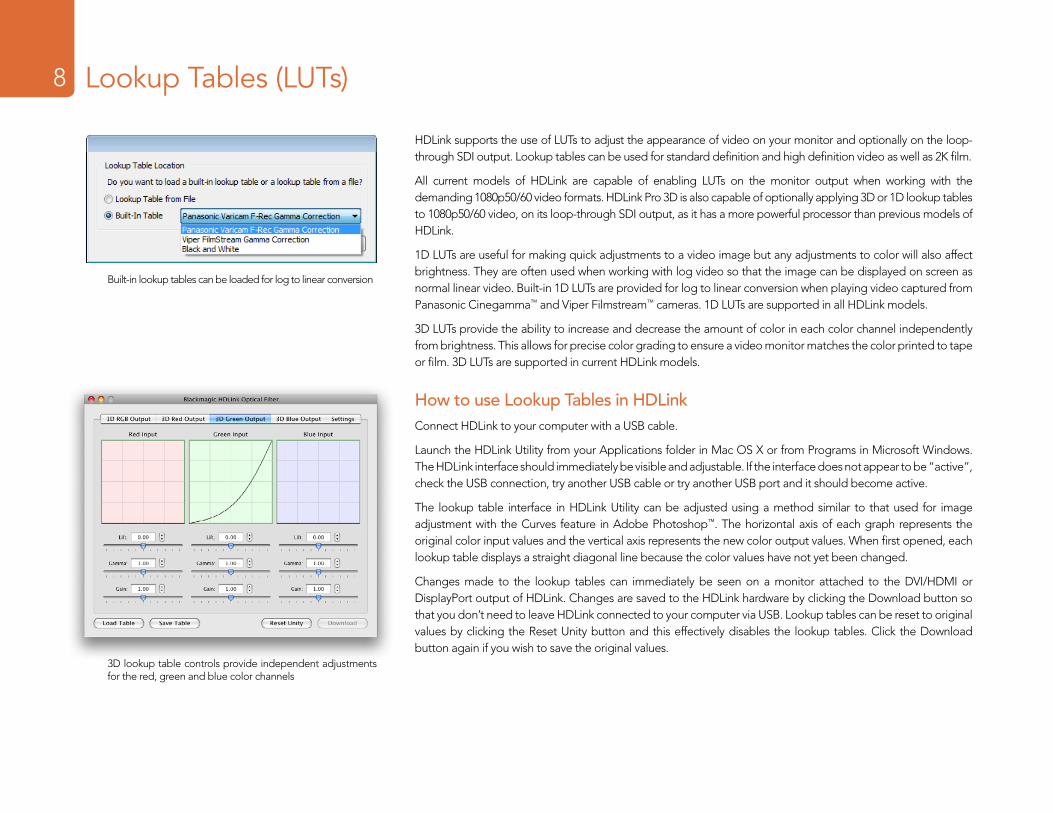
HDLink supports the use of LUTs to adjust the appearance of video on your monitor and optionally on the loop-through SDI output. Lookup tables can be used for standard definition and high definition video as well as 2K film.
All current models of HDLink are capable of enabling LUTs on the monitor output when working with the demanding 1080p50/60 video formats. HDLink Pro 3D is also capable of optionally applying 3D or 1D lookup tables to 1080p50/60 video, on its loop-through SDI output, as it has a more powerful processor than previous models of HDLink.
1D LUTs are useful for making quick adjustments to a video image but any adjustments to color will also affect brightness. They are often used when working with log video so that the image can be displayed on screen as normal linear video. Built-in 1D LUTs are provided for log to linear conversion when playing video captured from Panasonic Cinegamma™ and Viper Filmstream™ cameras. 1D LUTs are supported in all HDLink models.
3D LUTs provide the ability to increase and decrease the amount of color in each color channel independently from brightness. This allows for precise color grading to ensure a video monitor matches the color printed to tape or film. 3D LUTs are supported in current HDLink models.
How to use Lookup Tables in HDLinkConnect HDLink to your computer with a USB cable.
Launch the HDLink Utility from your Applications folder in Mac OS X or from Programs in Microsoft Windows. The HDLink interface should immediately be visible and adjustable. If the interface does not appear to be “active”, check the USB connection, try another USB cable or try another USB port and it should become active.
The lookup table interface in HDLink Utility can be adjusted using a method similar to that used for image adjustment with the Curves feature in Adobe Photoshop™. The horizontal axis of each graph represents the original color input values and the vertical axis represents the new color output values. When first opened, each lookup table displays a straight diagonal line because the color values have not yet been changed.
Changes made to the lookup tables can immediately be seen on a monitor attached to the DVI/HDMI or DisplayPort output of HDLink. Changes are saved to the HDLink hardware by clicking the Download button so that you don’t need to leave HDLink connected to your computer via USB. Lookup tables can be reset to original values by clicking the Reset Unity button and this effectively disables the lookup tables. Click the Download button again if you wish to save the original values.
Built-in lookup tables can be loaded for log to linear conversion
3D lookup table controls provide independent adjustments for the red, green and blue color channels
Installation9 Lookup Tables (LUTs)9
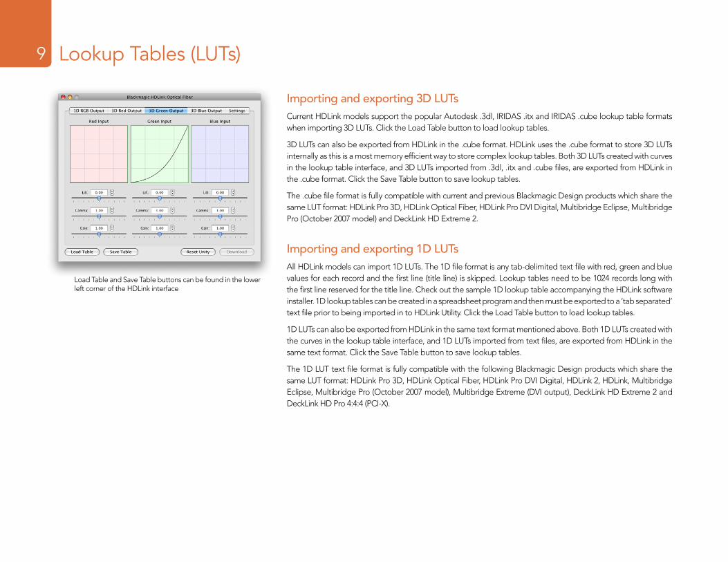
Importing and exporting 3D LUTsCurrent HDLink models support the popular Autodesk .3dl, IRIDAS .itx and IRIDAS .cube lookup table formats when importing 3D LUTs. Click the Load Table button to load lookup tables.
3D LUTs can also be exported from HDLink in the .cube format. HDLink uses the .cube format to store 3D LUTs internally as this is a most memory efficient way to store complex lookup tables. Both 3D LUTs created with curves in the lookup table interface, and 3D LUTs imported from .3dl, .itx and .cube files, are exported from HDLink in the .cube format. Click the Save Table button to save lookup tables.
The .cube file format is fully compatible with current and previous Blackmagic Design products which share the same LUT format: HDLink Pro 3D, HDLink Optical Fiber, HDLink Pro DVI Digital, Multibridge Eclipse, Multibridge Pro (October 2007 model) and DeckLink HD Extreme 2.
Importing and exporting 1D LUTsAll HDLink models can import 1D LUTs. The 1D file format is any tab-delimited text file with red, green and blue values for each record and the first line (title line) is skipped. Lookup tables need to be 1024 records long with the first line reserved for the title line. Check out the sample 1D lookup table accompanying the HDLink software installer. 1D lookup tables can be created in a spreadsheet program and then must be exported to a ‘tab separated’ text file prior to being imported in to HDLink Utility. Click the Load Table button to load lookup tables.
1D LUTs can also be exported from HDLink in the same text format mentioned above. Both 1D LUTs created with the curves in the lookup table interface, and 1D LUTs imported from text files, are exported from HDLink in the same text format. Click the Save Table button to save lookup tables.
The 1D LUT text file format is fully compatible with the following Blackmagic Design products which share the same LUT format: HDLink Pro 3D, HDLink Optical Fiber, HDLink Pro DVI Digital, HDLink 2, HDLink, Multibridge Eclipse, Multibridge Pro (October 2007 model), Multibridge Extreme (DVI output), DeckLink HD Extreme 2 and DeckLink HD Pro 4:4:4 (PCI-X).
Load Table and Save Table buttons can be found in the lower left corner of the HDLink interface
Welcome10 Settings10
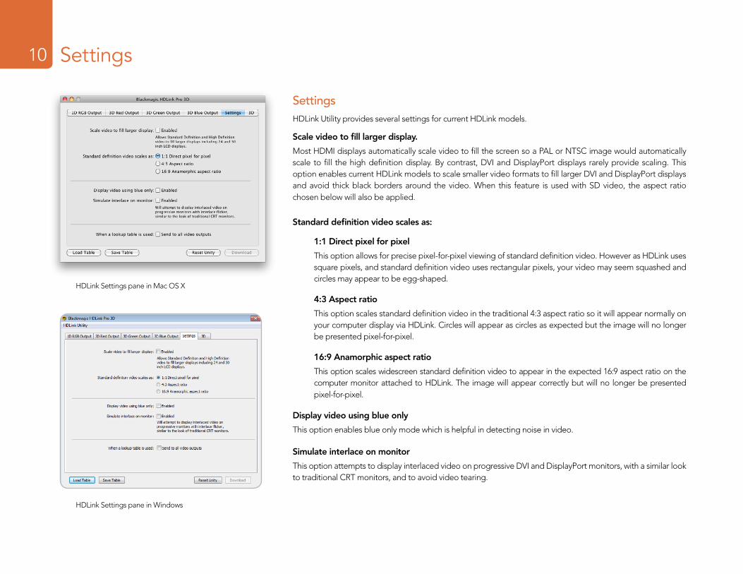
SettingsHDLink Utility provides several settings for current HDLink models.
Scale video to fill larger display.
Most HDMI displays automatically scale video to fill the screen so a PAL or NTSC image would automatically scale to fill the high definition display. By contrast, DVI and DisplayPort displays rarely provide scaling. This option enables current HDLink models to scale smaller video formats to fill larger DVI and DisplayPort displays and avoid thick black borders around the video. When this feature is used with SD video, the aspect ratio chosen below will also be applied.
Standard definition video scales as:
1:1 Direct pixel for pixel
This option allows for precise pixel-for-pixel viewing of standard definition video. However as HDLink uses square pixels, and standard definition video uses rectangular pixels, your video may seem squashed and circles may appear to be egg-shaped.
4:3 Aspect ratio
This option scales standard definition video in the traditional 4:3 aspect ratio so it will appear normally on your computer display via HDLink. Circles will appear as circles as expected but the image will no longer be presented pixel-for-pixel.
16:9 Anamorphic aspect ratio
This option scales widescreen standard definition video to appear in the expected 16:9 aspect ratio on the computer monitor attached to HDLink. The image will appear correctly but will no longer be presented pixel-for-pixel.
Display video using blue only
This option enables blue only mode which is helpful in detecting noise in video.
Simulate interlace on monitor
This option attempts to display interlaced video on progressive DVI and DisplayPort monitors, with a similar look to traditional CRT monitors, and to avoid video tearing.
HDLink Settings pane in Mac OS X
HDLink Settings pane in Windows
Welcome11 Settings11
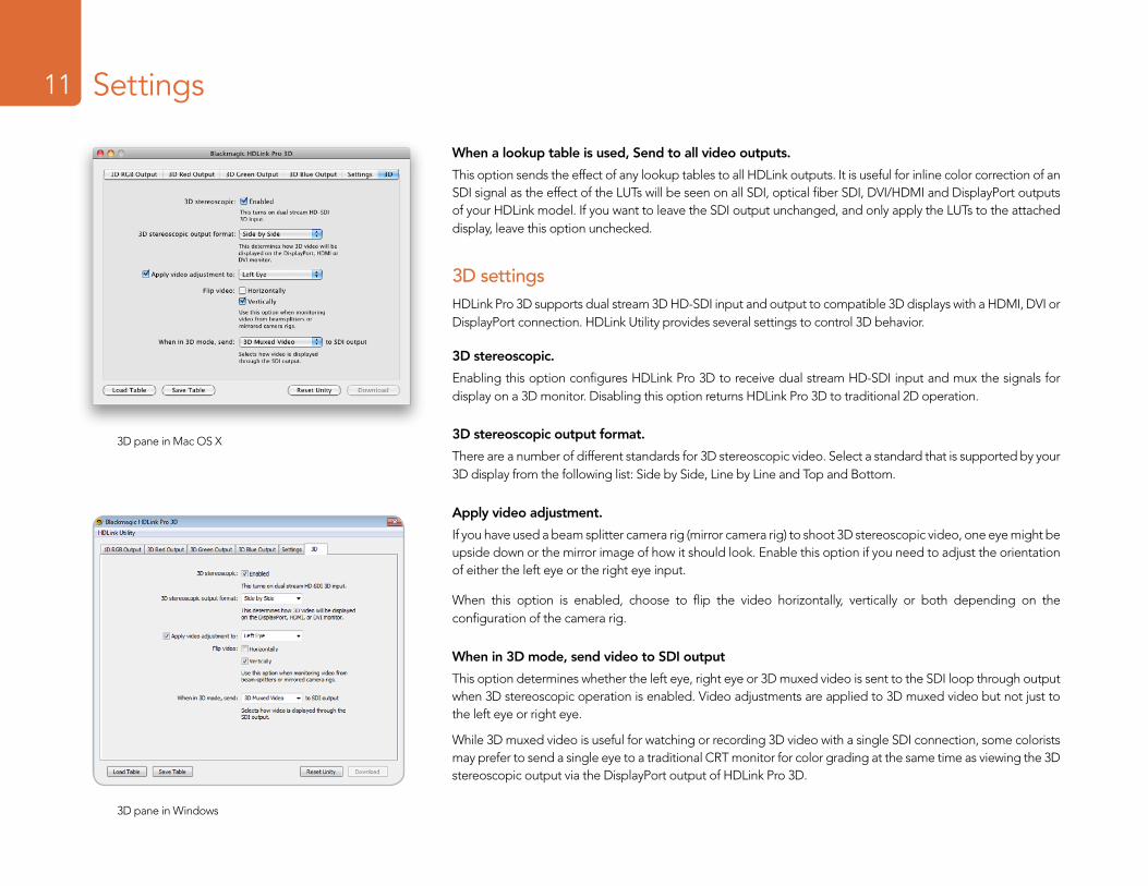
When a lookup table is used, Send to all video outputs.
This option sends the effect of any lookup tables to all HDLink outputs. It is useful for inline color correction of an SDI signal as the effect of the LUTs will be seen on all SDI, optical fiber SDI, DVI/HDMI and DisplayPort outputs of your HDLink model. If you want to leave the SDI output unchanged, and only apply the LUTs to the attached display, leave this option unchecked.
3D settingsHDLink Pro 3D supports dual stream 3D HD-SDI input and output to compatible 3D displays with a HDMI, DVI or DisplayPort connection. HDLink Utility provides several settings to control 3D behavior.
3D stereoscopic.
Enabling this option configures HDLink Pro 3D to receive dual stream HD-SDI input and mux the signals for display on a 3D monitor. Disabling this option returns HDLink Pro 3D to traditional 2D operation.
3D stereoscopic output format.
There are a number of different standards for 3D stereoscopic video. Select a standard that is supported by your 3D display from the following list: Side by Side, Line by Line and Top and Bottom.
Apply video adjustment.
If you have used a beam splitter camera rig (mirror camera rig) to shoot 3D stereoscopic video, one eye might be upside down or the mirror image of how it should look. Enable this option if you need to adjust the orientation of either the left eye or the right eye input.
When this option is enabled, choose to flip the video horizontally, vertically or both depending on the configuration of the camera rig.
When in 3D mode, send video to SDI output
This option determines whether the left eye, right eye or 3D muxed video is sent to the SDI loop through output when 3D stereoscopic operation is enabled. Video adjustments are applied to 3D muxed video but not just to the left eye or right eye.
While 3D muxed video is useful for watching or recording 3D video with a single SDI connection, some colorists may prefer to send a single eye to a traditional CRT monitor for color grading at the same time as viewing the 3D stereoscopic output via the DisplayPort output of HDLink Pro 3D.
3D pane in Mac OS X
3D pane in Windows
HDLink Models
12
Installation13 HDLink Pro DVI Digital13
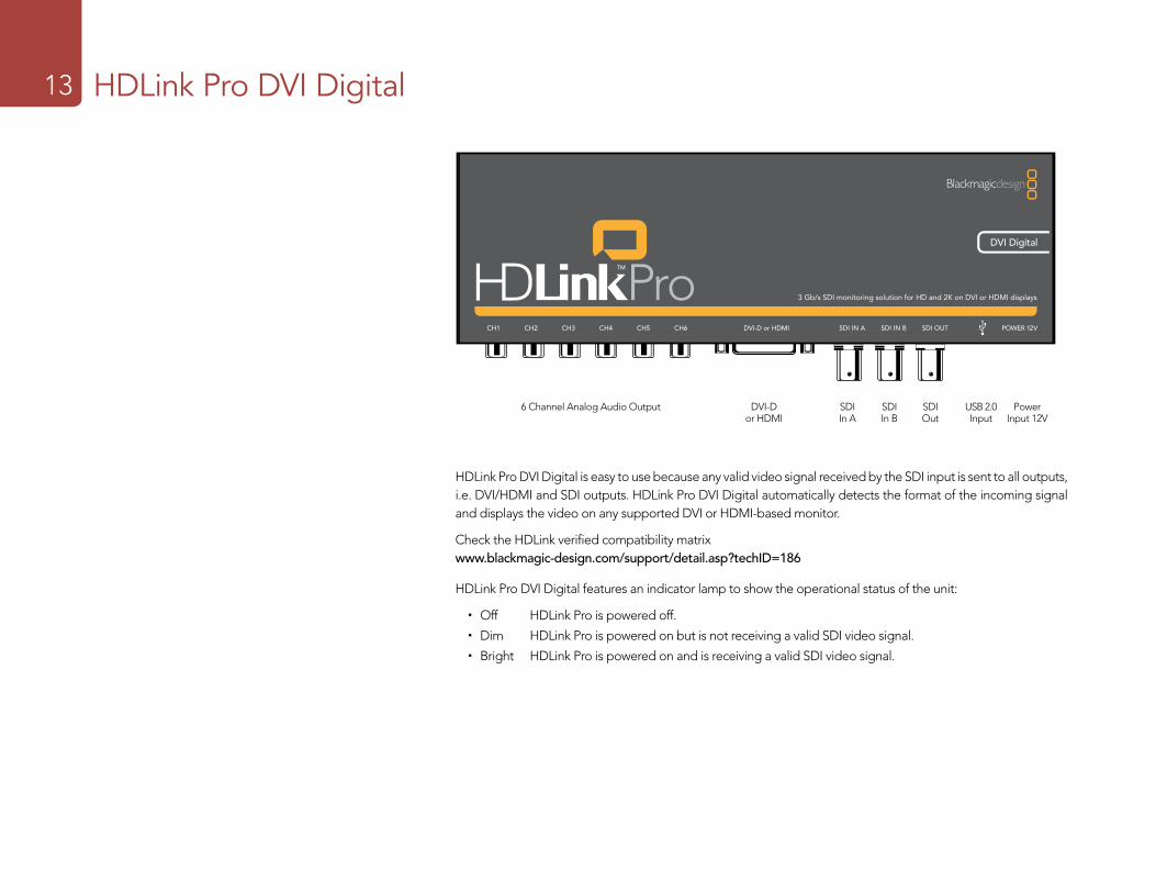
CH1 CH2 CH3 CH4 CH5 CH6 SDI IN SDI OUT OPTICAL OUT/IN POWER 12V
3 Gb/s SDI monitoring for DVI/HDMI displays
DVI-D or HDMI
HDLink Pro DVI Digital is easy to use because any valid video signal received by the SDI input is sent to all outputs, i.e. DVI/HDMI and SDI outputs. HDLink Pro DVI Digital automatically detects the format of the incoming signal and displays the video on any supported DVI or HDMI-based monitor.
Check the HDLink verified compatibility matrix www.blackmagic-design.com/support/detail.asp?techID=186
HDLink Pro DVI Digital features an indicator lamp to show the operational status of the unit:
� Off HDLink Pro is powered off.
� Dim HDLink Pro is powered on but is not receiving a valid SDI video signal.
� Bright HDLink Pro is powered on and is receiving a valid SDI video signal.
6 Channel Analog Audio Output DVI-D or HDMI
SDI In A
SDI In B
SDI Out
USB 2.0 Input
Power Input 12V
Installation14 HDLink Pro DVI Digital14
Valid video signals supported by HDLink Pro DVI Digital include 2K, HD1080, HD720, NTSC and PAL. Computer video formats are generally not supported unless they coincidentally match a TV format. HDLink can be used to monitor the output of a Blackmagic Design DVI Extender in either Video or Extender (computer resolution) modes. Detailed information is available in the DVI Extender manual. Please see the following HDLink specifications link on the Blackmagic Design website for a full listing of current formats supported via DVI and HDMI displays. Check www.blackmagic-design.com/products/hdlink/techspecs/
HDLink is preconfigured for you, requiring no initial setup to connect. Your HDLink will simply run without changing any settings, however, if you would like to update the firmware, modify settings or load custom gamma tables, then use the HDLink Utility software. This can be downloaded from the Blackmagic Design web site support page. Check www.blackmagic-design.com/support/
HDLink Pro DVI Digital uses the same software as other HDLink models and shares the same software interface for changing settings including 3D LUTs. 3D and 1D lookup tables can be applied to the DVI/HDMI output of HDLink Pro DVI Digital. If HDLink Pro DVI Digital is configured to send lookup tables to all video outputs, the lookup tables will be applied to the SDI output in addition to the DVI/HDMI output.
DVI-D monitors are shown in most of the connection diagrams shown for this HDLink model. An HDMI display can be used in all cases except for 2K monitoring as HDMI displays do not have sufficient resolution to display a full 2K image. HDMI displays are best for use with HD720p50 as most DVI displays do not support this format. The included DVI-to-HDMI adapter can be used to attach an HDMI display to the DVI output of HDLink Pro DVI Digital.
HDLink Pro DVI Digital provides two SDI inputs which can be used for standard definition SDI, HD-SDI 4:2:2, Dual Link HD-SDI 4:4:4, 3 Gb/s HD-SDI 4:4:4 video or 2K film as shown in the connection diagrams of this manual.
The consumer level analog audio outputs are fully compatible with a wide range of consumer HiFi equipment and are perfect for monitoring of stereo audio or even up to 6 channels of audio. 2 channel audio output via HDMI is provided for maximum compatibility with HDMI TVs and monitors.
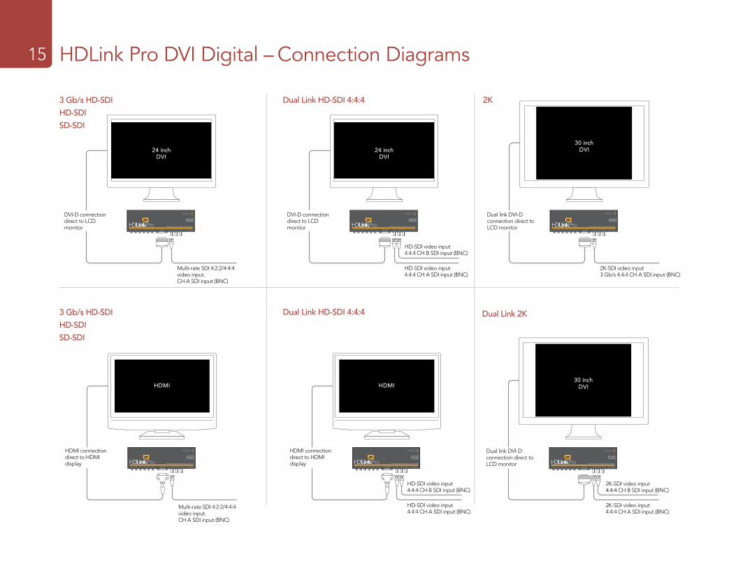
Installation15 HDLink Pro DVI Digital – Connection Diagrams15
Dual Link HD-SDI 4:4:4
24 inchDVI
HD-SDI video input 4:4:4 CH A SDI input (BNC)
HD-SDI video input 4:4:4 CH B SDI input (BNC)
DVI-D connection direct to LCD monitor
24 inchDVI
Multi-rate SDI 4:2:2/4:4:4 video input. CH A SDI input (BNC)
DVI-D connection direct to LCD monitor
2K
30 inchDVI
2K-SDI video input 3 Gb/s 4:4:4 CH A SDI input (BNC)
Dual link DVI-D connection direct to LCD monitor
3 Gb/s HD-SDI
HD-SDI
SD-SDI
3 Gb/s HD-SDI
HD-SDI
SD-SDI
HDMI
HDMI connection direct to HDMI display
Multi-rate SDI 4:2:2/4:4:4 video input. CH A SDI input (BNC)
HDMI
HDMI connection direct to HDMI display
Dual Link HD-SDI 4:4:4
24 inchDVI
HD-SDI video input 4:4:4 CH A SDI input (BNC)
HD-SDI video input 4:4:4 CH B SDI input (BNC)
30 inchDVI
2K-SDI video input 4:4:4 CH A SDI input (BNC)
2K-SDI video input 4:4:4 CH B SDI input (BNC)
Dual Link 2K
Dual link DVI-D connection direct to LCD monitor

Installation16 HDLink Pro DVI Digital16 HDLink Pro 3D DisplayPort16
HDLink Pro 3D is easy to use because any valid video signal received by the SDI input is sent to all outputs, i.e. DisplayPort and SDI outputs. HDLink Pro 3D automatically detects the format of the incoming signal and displays the video on any supported DisplayPort-based monitor.
Check the HDLink verified compatibility matrix www.blackmagic-design.com/support/detail.asp?techID=186
HDLink Pro 3D features an indicator lamp to show the operational status of the unit:
� Off HDLink Pro is powered off.
� Dim HDLink Pro is powered on but is not receiving a valid SDI video signal.
� Bright HDLink Pro is powered on and is receiving a valid SDI video signal.
6 Channel Analog Audio Output DisplayPort SDI In A
SDI In B
SDI Out
USB 2.0 Input
Power Input 12V
Installation17 HDLink Pro DVI Digital17 HDLink Pro 3D DisplayPort17
Valid video signals supported by HDLink Pro 3D include 2K, HD1080, HD720, NTSC and PAL. Computer video formats are generally not supported unless they coincidentally match a TV format. HDLink can be used to monitor the output of a Blackmagic Design DVI Extender in either Video or Extender (computer resolution) modes. Detailed information is available in the DVI Extender manual. Please see the following HDLink specifications link on the Blackmagic Design website for a full listing of current formats supported via DisplayPort displays. Check www.blackmagic-design.com/products/hdlink/techspecs/
HDLink is preconfigured for you, requiring no initial setup to connect. Your HDLink will simply run without changing any settings, however, if you would like to update the firmware, enable 3D stereoscopic dual stream input, modify settings or load custom gamma tables, then use the HDLink Utility software. This can be downloaded from the Blackmagic Design web site support page. Check www.blackmagic-design.com/support/
HDLink Pro 3D uses the same software as other HDLink models and shares the same software interface for changing settings including 3D LUTs. 3D and 1D lookup tables can be applied to the DisplayPort output of HDLink Pro 3D. If HDLink Pro 3D is configured to send lookup tables to all video outputs, the lookup tables will be applied to the SDI output in addition to the DisplayPort output.
DisplayPort monitors are shown in all of the connection diagrams for this HDLink model. However HDLink Pro 3D supports the use of DisplayPort, DVI-D and HDMI displays. In order to connect to DVI-D or HDMI displays, a third party DisplayPort-to-DVI-D, DisplayPort-to-Dual Link DVI-D or DisplayPort-to-HDMI adapter is required.
An HDMI display can be used in all cases except for 2K monitoring as HDMI displays do not have sufficient resolution to display a full 2K image. HDMI displays are also best for use with HD720p50 as most DisplayPort and DVI displays do not support this format.
A single-link DVI-D display can be used in all cases except for 2K monitoring as DVI-D displays do not have sufficient resolution to display a full 2K image. 30” dual-link DVI-D displays can be used in all cases including 2K monitoring.
HDLink Pro 3D provides two SDI inputs which can be used for standard definition SDI, HD-SDI 4:2:2, Dual Link HD-SDI 4:4:4, 3 Gb/s HD-SDI 4:4:4 video or 2K film as shown in the connection diagrams of this manual.
The consumer level analog audio outputs are fully compatible with a wide range of consumer HiFi equipment and are perfect for monitoring of stereo audio or even up to 6 channels of audio. Audio output via DisplayPort is also supported.
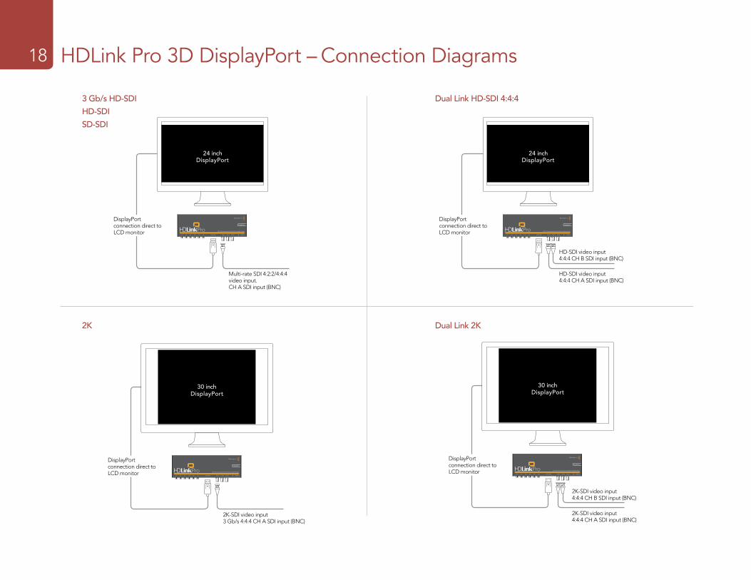
Installation18 HDLink Pro DVI Digital – Connection Diagrams18 HDLink Pro 3D DisplayPort – Connection Diagrams18
24 inchDisplayPort
DisplayPort connection direct to LCD monitor
24 inchDisplayPort
Multi-rate SDI 4:2:2/4:4:4 video input. CH A SDI input (BNC)
DisplayPort connection direct to LCD monitor
30 inchDisplayPort
DisplayPort connection direct to LCD monitor
30 inchDisplayPort
2K-SDI video input 3 Gb/s 4:4:4 CH A SDI input (BNC)
DisplayPort connection direct to LCD monitor
3 Gb/s HD-SDI
HD-SDI
SD-SDI
Dual Link HD-SDI 4:4:4
2K Dual Link 2K
2K-SDI video input 4:4:4 CH A SDI input (BNC)
2K-SDI video input 4:4:4 CH B SDI input (BNC)
HD-SDI video input 4:4:4 CH A SDI input (BNC)
HD-SDI video input 4:4:4 CH B SDI input (BNC)
Installation19 HDLink Pro DVI Digital – Connection Diagrams19 HDLink Pro 3D DisplayPort – 3D Connection Diagrams19
3D
3D
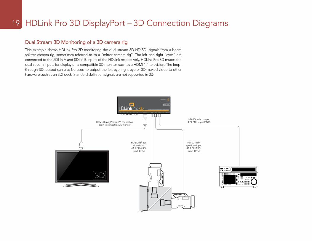
Dual Stream 3D Monitoring of a 3D camera rigThis example shows HDLink Pro 3D monitoring the dual stream 3D HD-SDI signals from a beam splitter camera rig, sometimes referred to as a “mirror camera rig”. The left and right “eyes” are connected to the SDI In A and SDI in B inputs of the HDLink respectively. HDLink Pro 3D muxes the dual stream inputs for display on a compatible 3D monitor, such as a HDMI 1.4 television. The loop-through SDI output can also be used to output the left eye, right eye or 3D muxed video to other hardware such as an SDI deck. Standard definition signals are not supported in 3D.
HDMI, DisplayPort or DVI connection direct to compatible 3D monitor
HD-SDI left eye video input
4:2:2 CH A SDI input (BNC)
HD-SDI right eye video input 4:2:2 CH B SDI
input (BNC)
HD-SDI video output 4:2:2 SDI output (BNC)
Installation20 HDLink Pro DVI Digital – Connection Diagrams20 HDLink Pro 3D DisplayPort – 3D Connection Diagrams20
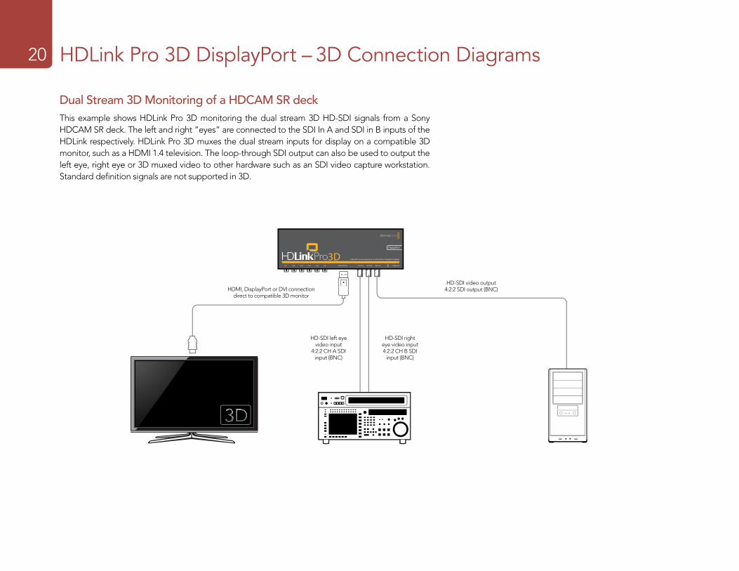
Dual Stream 3D Monitoring of a HDCAM SR deckThis example shows HDLink Pro 3D monitoring the dual stream 3D HD-SDI signals from a Sony HDCAM SR deck. The left and right “eyes” are connected to the SDI In A and SDI in B inputs of the HDLink respectively. HDLink Pro 3D muxes the dual stream inputs for display on a compatible 3D monitor, such as a HDMI 1.4 television. The loop-through SDI output can also be used to output the left eye, right eye or 3D muxed video to other hardware such as an SDI video capture workstation. Standard definition signals are not supported in 3D.
3D
3D
HDMI, DisplayPort or DVI connection direct to compatible 3D monitor
HD-SDI right eye video input 4:2:2 CH B SDI
input (BNC)
HD-SDI video output 4:2:2 SDI output (BNC)
HD-SDI left eye video input
4:2:2 CH A SDI input (BNC)
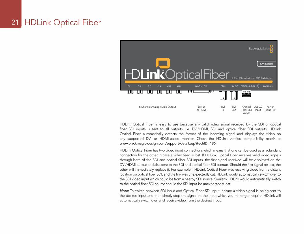
Installation21 HDLink Optical Fiber21
HDLink Optical Fiber is easy to use because any valid video signal received by the SDI or optical fiber SDI inputs is sent to all outputs, i.e. DVI/HDMI, SDI and optical fiber SDI outputs. HDLink Optical Fiber automatically detects the format of the incoming signal and displays the video on any supported DVI or HDMI-based monitor. Check the HDLink verified compatibility matrix at www.blackmagic-design.com/support/detail.asp?techID=186
HDLink Optical Fiber has two video input connections which means that one can be used as a redundant connection for the other in case a video feed is lost. If HDLink Optical Fiber receives valid video signals through both of the SDI and optical fiber SDI inputs, the first signal received will be displayed on the DVI/HDMI output and also sent to the SDI and optical fiber SDI outputs. Should the first signal be lost, the other will immediately replace it. For example if HDLink Optical Fiber was receiving video from a distant location via optical fiber SDI, and the link was unexpectedly cut, HDLink would automatically switch over to the SDI video input which could be from a nearby SDI source. Similarly HDLink would automatically switch to the optical fiber SDI source should the SDI input be unexpectedly lost.
Note: To switch between SDI input and Optical Fiber SDI input, ensure a video signal is being sent to the desired input and then simply stop the signal on the input which you no longer require. HDLink will automatically switch over and receive video from the desired input.
DVI-D or HDMI
SDI In
SDI Out
Optical Fiber SDI
Out/In
CH1 CH2 CH3 CH4 CH5 CH6 SDI IN SDI OUT OPTICAL OUT/IN POWER 12V
3 Gb/s SDI monitoring for DVI/HDMI displays
DVI-D or HDMI
6 Channel Analog Audio Output USB 2.0 Input
Power Input 12V
Installation22 HDLink Optical Fiber22
HDLink Optical Fiber features an indicator lamp to show the operational status of the unit:
� Off HDLink Optical Fiber is powered off. � Dim HDLink Optical Fiber is powered on but is not receiving a valid SDI video signal via either
SDI or Optical Fiber SDI inputs. � Bright HDLink Optical Fiber is powered on and is receiving a valid SDI video signal via either or both
SDI and Optical Fiber SDI inputs.
Valid video signals supported by HDLink Optical Fiber include 2K, HD1080, HD720, NTSC and PAL. Computer video formats are generally not supported unless they coincidentally match a TV format. HDLink can be used to monitor the output of a Blackmagic Design DVI Extender in either Video or Extender (computer resolution) modes. Detailed information is available in the DVI Extender manual. Please see the following HDLink specifications link for a full listing of current formats supported via DVI and HDMI displays. www.blackmagic-design.com/products/hdlink/techspecs/
HDLink is preconfigured for you, requiring no initial setup to connect. Your HDLink will simply run without changing any settings, however, if you would like to update the firmware, modify settings or load custom gamma tables, then use the HDLink Utility software. This can be downloaded from the Blackmagic Design web site support page. Check www.blackmagic-design.com/support/
HDLink Optical Fiber uses the same software as other HDLink models and shares the same software interface for changing settings including 3D LUTs. 3D and 1D lookup tables can be applied to the DVI/HDMI output of HDLink Optical Fiber. If HDLink Optical Fiber is configured to send lookup tables to all video outputs, the lookup tables will be applied to both the SDI and optical fiber SDI outputs in addition to the DVI/HDMI output.
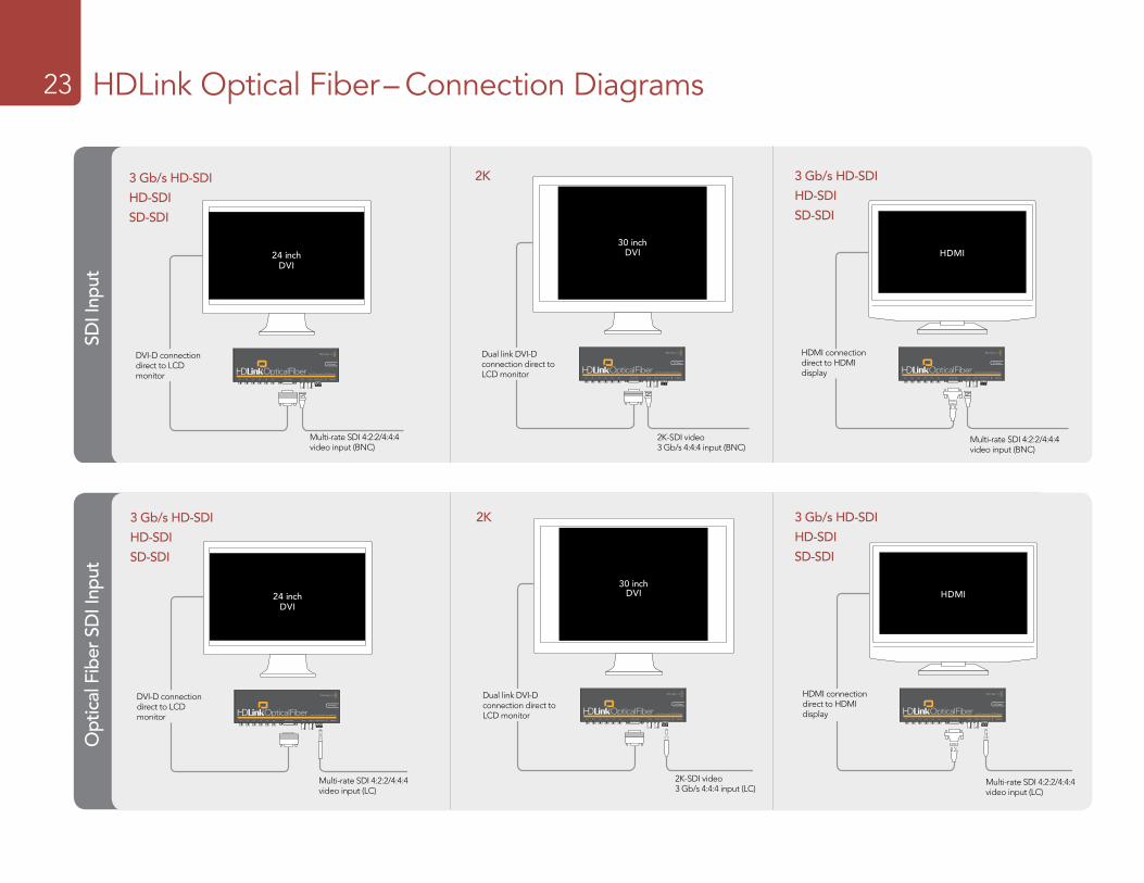
DVI-D monitors are shown in most of the connection diagrams shown for this HDLink model. An HDMI display can be used in all cases except for 2K monitoring as HDMI displays do not have sufficient resolution to display a full 2K image. HDMI displays are best for use with HD720p50 as most DVI displays do not support this format. The included DVI-to-HDMI adapter can be used to attach an HDMI display to the DVI output of HDLink.
HDLink Optical Fiber provides SDI and optical fiber SDI inputs which can be used for standard definition SDI, HD-SDI 4:2:2, 3 Gb/s HD-SDI 4:4:4 video or 2K film.
The fiber optic module, included with HDLink Optical Fiber, is a standard SFP transceiver module which includes an LC connector port for attaching fiber optic cables. While other kinds of optical connectors exist, the SMPTE standard for Optical Fiber SDI specifies that LC type optical fiber connectors be used and this makes it easy for all SMPTE compliant optical equipment to connect together.
The consumer level analog audio outputs are fully compatible with a wide range of consumer HiFi equipment and are perfect for monitoring of stereo audio or even up to 6 channels of audio. 2 channel audio output via HDMI is provided for maximum compatibility with HDMI TVs and monitors.
Installation23 HDLink Optical Fiber– Connection Diagrams23
3 Gb/s HD-SDI
HD-SDI
SD-SDI
24 inch
CH1 CH2 CH3 CH4 CH5 CH6 SDI IN SDI OUT OPTICAL OUT/IN POWER 12V
3 Gb/s SDI monitoring for DVI/HDMI displays
DVI-D or HDMI
DVI
DVI-D connection direct to LCD monitor
2K
30 inch
CH1 CH2 CH3 CH4 CH5 CH6 SDI IN SDI OUT OPTICAL OUT/IN POWER 12V
3 Gb/s SDI monitoring for DVI/HDMI displays
DVI-D or HDMI
DVI
2K-SDI video 3 Gb/s 4:4:4 input (BNC)
Dual link DVI-D connection direct to LCD monitor
CH1 CH2 CH3 CH4 CH5 CH6 SDI IN SDI OUT OPTICAL OUT/IN POWER 12V
3 Gb/s SDI monitoring for DVI/HDMI displays
DVI-D or HDMI
HDMI
HDMI connection direct to HDMI display
SDI I
nput
3 Gb/s HD-SDI
HD-SDI
SD-SDI
24 inch
CH1 CH2 CH3 CH4 CH5 CH6 SDI IN SDI OUT OPTICAL OUT/IN POWER 12V
3 Gb/s SDI monitoring for DVI/HDMI displays
DVI-D or HDMI
DVI
DVI-D connection direct to LCD monitor
2K
30 inch
CH1 CH2 CH3 CH4 CH5 CH6 SDI IN SDI OUT OPTICAL OUT/IN POWER 12V
3 Gb/s SDI monitoring for DVI/HDMI displays
DVI-D or HDMI
DVI
2K-SDI video 3 Gb/s 4:4:4 input (LC)
Dual link DVI-D connection direct to LCD monitor
CH1 CH2 CH3 CH4 CH5 CH6 SDI IN SDI OUT OPTICAL OUT/IN POWER 12V
3 Gb/s SDI monitoring for DVI/HDMI displays
DVI-D or HDMI
HDMI
HDMI connection direct to HDMI display
Opt
ical
Fib
er S
DI I
nput
Multi-rate SDI 4:2:2/4:4:4 video input (BNC)
3 Gb/s HD-SDI
HD-SDI
SD-SDI
Multi-rate SDI 4:2:2/4:4:4 video input (BNC)
Multi-rate SDI 4:2:2/4:4:4 video input (LC)
Multi-rate SDI 4:2:2/4:4:4 video input (LC)
3 Gb/s HD-SDI
HD-SDI
SD-SDI

Helpful Information
24
Troubleshooting25
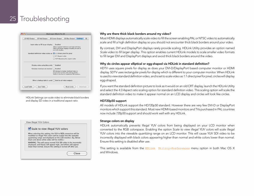
Why are there thick black borders around my video?Most HDMI displays automatically scale video to fill the screen enabling PAL or NTSC video to automatically scale and fill a high definition display so you should not encounter thick black borders around your video.
By contrast, DVI and DisplayPort displays rarely provide scaling. HDLink Utility provides an option named Scale video to fill larger display. This option enables current HDLink models to scale smaller video formats to fill larger DVI and DisplayPort displays and avoid thick black borders around the video.
Why do circles appear elliptical or egg-shaped via HDLink in standard definition?HDTV uses square pixels for display as does your DVI-D/DisplayPort based computer monitor or HDMI display. SDTV uses rectangular pixels for display which is different to your computer monitor. When HDLink is used to view standard definition video, and is set to scale video as 1:1 direct pixel for pixel, circles will display egg-shaped.
If you want the standard definition picture to look as it would on an old CRT display, launch the HDLink Utility and select the 4:3 Aspect ratio scaling option for standard definition video. This scaling option will scale the standard definition video to make it appear normal on an LCD display and circles will look like circles.
HD720p50 supportAll models of HDLink support the HD720p50 standard. However there are very few DVI-D or DisplayPort monitors which support this standard. Most new HDMI-based monitors and TVs purchased in PAL countries now include 720p50 support and should work well with any HDLink.
Strange colors on displayHDLink automatically prevents illegal YUV colors from being displayed on your LCD monitor when converted to the RGB colorspace. Enabling the option Scale to view illegal YUV colors will scale illegal YUV colors into the viewable quantizing range on an LCD monitor. This will cause YUV SDI video to be incorrectly displayed with black colors appearing higher than normal and white colors lower than normal. Ensure this setting is disabled after use.
This setting is available from the HDLink Utility>Preferences menu option in both Mac OS X and Windows.
HDLink Settings can scale video to eliminate black borders and display SD video in a traditional aspect ratio
Troubleshooting26
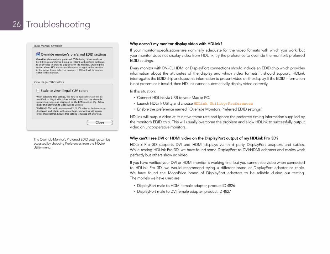
Why doesn’t my monitor display video with HDLink?
If your monitor specifications are nominally adequate for the video formats with which you work, but your monitor does not display video from HDLink, try the preference to override the monitor’s preferred EDID settings.
Every monitor with DVI-D, HDMI or DisplayPort connections should include an EDID chip which provides information about the attributes of the display and which video formats it should support. HDLink interrogates the EDID chip and uses this information to present video on the display. If the EDID information is not present or is invalid, then HDLink cannot automatically display video correctly.
In this situation:
� Connect HDLink via USB to your Mac or PC. � Launch HDLink Utility and choose HDLink Utility>Preferences � Enable the preference named “Override Monitor’s Preferred EDID settings”.
HDLink will output video at its native frame rate and ignore the preferred timing information supplied by the monitor’s EDID chip. This will usually overcome the problem and allow HDLink to successfully output video on uncooperative monitors.
Why can’t I see DVI or HDMI video on the DisplayPort output of my HDLink Pro 3D?
HDLink Pro 3D supports DVI and HDMI displays via third party DisplayPort adapters and cables. While testing HDLink Pro 3D, we have found some DisplayPort to DVI/HDMI adapters and cables work perfectly but others show no video.
If you have verified your DVI or HDMI monitor is working fine, but you cannot see video when connected to HDLink Pro 3D, we would recommend trying a different brand of DisplayPort adapter or cable. We have found the MonoPrice brand of DisplayPort adapters to be reliable during our testing. The models we have used are:
� DisplayPort male to HDMI female adapter, product ID 4826 � DisplayPort male to DVI female adapter, product ID 4827
The Override Monitor’s Preferred EDID settings can be accessed by choosing Preferences from the HDLink Utility menu.
Troubleshooting27
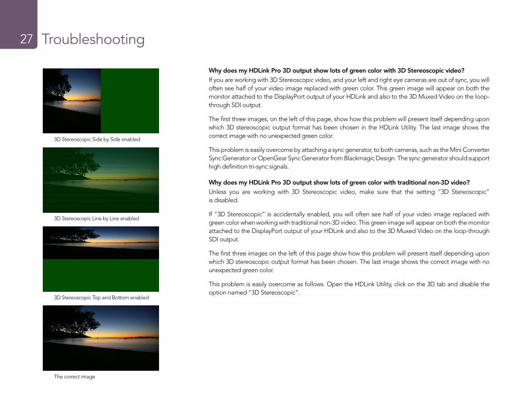
Why does my HDLink Pro 3D output show lots of green color with 3D Stereoscopic video?If you are working with 3D Stereoscopic video, and your left and right eye cameras are out of sync, you will often see half of your video image replaced with green color. This green image will appear on both the monitor attached to the DisplayPort output of your HDLink and also to the 3D Muxed Video on the loop-through SDI output.
The first three images, on the left of this page, show how this problem will present itself depending upon which 3D stereoscopic output format has been chosen in the HDLink Utility. The last image shows the correct image with no unexpected green color.
This problem is easily overcome by attaching a sync generator, to both cameras, such as the Mini Converter Sync Generator or OpenGear Sync Generator from Blackmagic Design. The sync generator should support high definition tri-sync signals.
Why does my HDLink Pro 3D output show lots of green color with traditional non-3D video?Unless you are working with 3D Stereoscopic video, make sure that the setting “3D Stereoscopic” is disabled.
If “3D Stereoscopic” is accidentally enabled, you will often see half of your video image replaced with green color when working with traditional non-3D video. This green image will appear on both the monitor attached to the DisplayPort output of your HDLink and also to the 3D Muxed Video on the loop-through SDI output.
The first three images on the left of this page show how this problem will present itself depending upon which 3D stereoscopic output format has been chosen. The last image shows the correct image with no unexpected green color.
This problem is easily overcome as follows. Open the HDLink Utility, click on the 3D tab and disable the option named “3D Stereoscopic”.
3D Stereoscopic Side by Side enabled
3D Stereoscopic Line by Line enabled
3D Stereoscopic Top and Bottom enabled
The correct image
Support28
If things go wrong
There are four steps to getting help.Step 1. Check out the Blackmagic Design web site www.blackmagic-design.com and click on the “Support” page for the latest support information.
Step 2. Call your dealer.
Your dealer will have the latest technical updates from Blackmagic Design and should be able to give you immediate assistance. We also recommend you check out the support options your dealer offers as they can arrange various support plans based on your workflow requirements.
Step 3. The next option is to email us with your questions using the web form at www.blackmagic-design.com/support/contact
Step 4. Phone a Blackmagic Design support office. Check our web site for current support phone numbers in your area. www.blackmagic-design.com/company.
Please provide us with as much information as possible regarding your technical problem and system specifications so that we may try to respond to your problem as quickly as possible.
Developer Information
29
Developer Information30
Frame Structure
� Transmitted at 23.98, 24 or 25 frames per second as a Progressive Segmented Frame. � Active video is 2048 pixels wide by 1556 lines deep. � Total lines per frame : 1650 � Active words per line are 1535. One word consists of a 10-bit sample for each of the four data streams,
i.e. a total of 40 bits. See the diagram named Blackmagic 2K Format - Data Stream Format. � Total active lines : 1556 � Total words per line : 1875 for 23.98/24Hz and 1800 for 25Hz. � Fields per frame : 2, 825 lines each
� Active lines located on lines 16-793 (field 1) and 841-1618 (field 2).
Transport Structure
� Based on SMPTE 372M Dual Link mapping and SMPTE 425M-B support for mapping SMPTE 372M into a single 3 Gb/s link.
� Timing reference signals, line number and line CRC insertion is the same as above. � Optional ancillary data is inserted into both virtual interfaces. � At present, only audio data is included: as per standard HD audio insertion (SMPTE S299M) the audio
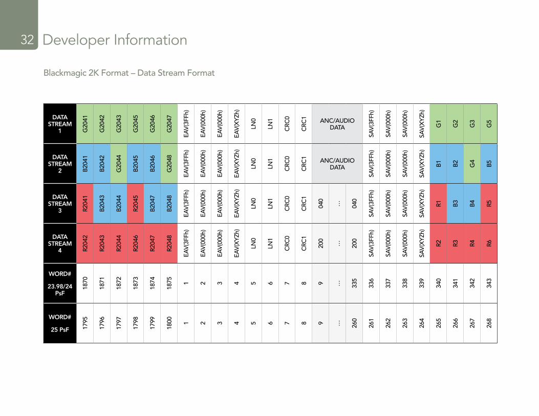
data packets are carried on data stream two and audio control packets are carried on data stream one. � During active video, 10-bit Red, Green and Blue data is sent in the following sequence:
Data stream1: Green_1, Green_2, Green_3, Green_5...Green_2047
Data stream 2: Blue_1, Blue_2, Green_4, Blue_5...Green_2048.
Data stream 3: Red_1, Blue_3, Blue_4, Red_5...Blue_2048.
Data stream 4: Red_2, Red_3, Red_4, Red_6...Red_2048.
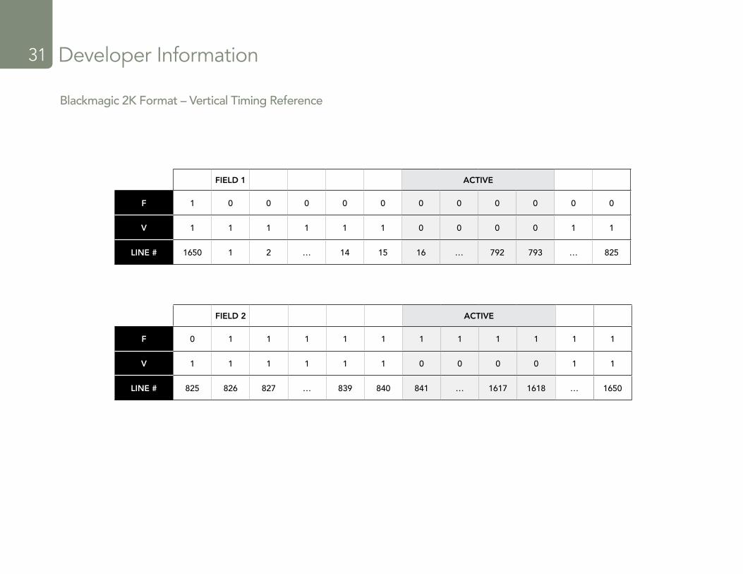
The diagram, Vertical Timing Reference, shows the vertical timing details with line numbers and Field, Vertical and Horizontal bits for the Timing Reference Signal codes.
The diagram, Data Stream Format, shows the data stream formats around the optional ancillary data section of the horizontal line. Note that each active pixel takes up three samples.
Blackmagic 2K Format – OverviewThe latest Blackmagic Design products use the new 3 Gb/s SDI video, which allows twice the data rate of traditional HD-SDI video. We thought it would be a really nice idea to add 2K film support, via this new 3 Gb/s SDI technology, so we could simplify feature film workflows. With the popularity of Blackmagic Design editing systems worldwide, now thousands of people can benefit from a feature film workflow revolution.
This information includes everything product developers need to know for building native 2K SDI equipment. Of course, all Blackmagic products can be updated, so if the television industry adopts an alternative SDI-based film standard, we can add support for that too!
Developer Information31
FIELD 1 ACTIVE
F 1 0 0 0 0 0 0 0 0 0 0 0
V 1 1 1 1 1 1 0 0 0 0 1 1
LINE # 1650 1 2 … 14 15 16 … 792 793 … 825
Blackmagic 2K Format – Vertical Timing Reference
FIELD 2 ACTIVE
F 0 1 1 1 1 1 1 1 1 1 1 1
V 1 1 1 1 1 1 0 0 0 0 1 1
LINE # 825 826 827 … 839 840 841 … 1617 1618 … 1650
Developer Information32
DATA STREAM
1 G20
41
G20
42
G20
43
G20
45
G20
46
G20
47
EAV
(3FF
h)
EAV
(000
h)
EAV
(000
h)
EAV
(XYZ
h)
LN0
LN1
CRC
0
CRC
1 ANC/AUDIO DATA
SAV
(3FF
h)
SAV
(000
h)
SAV
(000
h)
SAV
(XYZ
h)
G1
G2
G3
G5
DATA STREAM
2 B20
41
B20
42
G20
44
B20
45
B20
46
G20
48
EAV
(3FF
h)
EAV
(000
h)
EAV
(000
h)
EAV
(XYZ
h)
LN0
LN1
CRC
0
CRC
1 ANC/AUDIO DATA
SAV
(3FF
h)
SAV
(000
h)
SAV
(000
h)
SAV
(XYZ
h)
B1
B2
G4
B5
DATA STREAM
3 R204
1
B20
43
B20
44
R204
5
B20
47
B20
48
EAV
(3FF
h)
EAV
(000
h)
EAV
(000
h)
EAV
(XYZ
h)
LN0
LN1
CRC
0
CRC
1
040
… 040
SAV
(3FF
h)
SAV
(000
h)
SAV
(000
h)
SAV
(XYZ
h)
R1 B3
B4 R5
DATA STREAM
4 R204
2
R204
3
R204
4
R204
6
R204
7
R204
8
EAV
(3FF
h)
EAV
(000
h)
EAV
(000
h)
EAV
(XYZ
h)
LN0
LN1
CRC
0
CRC
1
200
… 200
SAV
(3FF
h)
SAV
(000
h)
SAV
(000
h)
SAV
(XYZ
h)
R2 R3 R4 R6
WORD#
23.98/24 PsF
1870
1871
1872
1873
1874
1875 1 2 3 4 5 6 7 8 9 … 335
336
337
338
339
340
341
342
343
WORD#
25 PsF 1795
1796
1797
1798
1799
1800 1 2 3 4 5 6 7 8 9 … 260
261
262
263
264
265
266
267
268
Blackmagic 2K Format – Data Stream Format
Previous HDLink Models
33
Installation34 Using HDLink Utility34
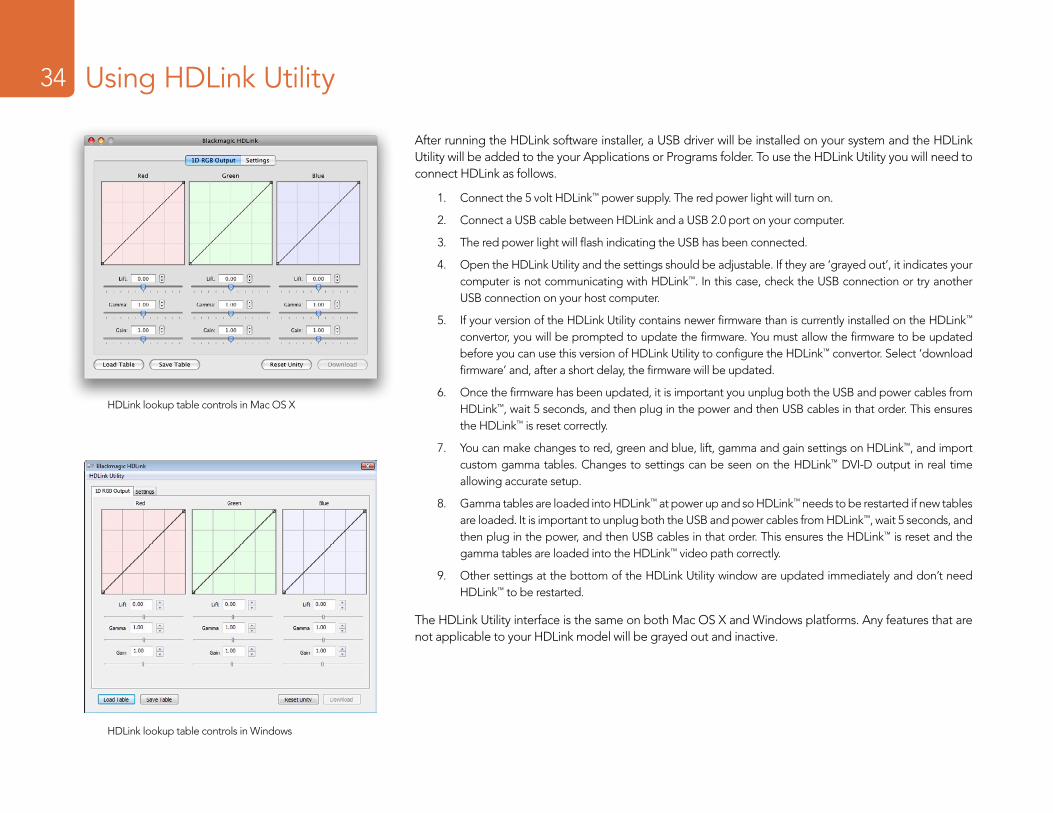
After running the HDLink software installer, a USB driver will be installed on your system and the HDLink Utility will be added to the your Applications or Programs folder. To use the HDLink Utility you will need to connect HDLink as follows.
1. Connect the 5 volt HDLink™ power supply. The red power light will turn on.
2. Connect a USB cable between HDLink and a USB 2.0 port on your computer.
3. The red power light will flash indicating the USB has been connected.
4. Open the HDLink Utility and the settings should be adjustable. If they are ‘grayed out’, it indicates your computer is not communicating with HDLink™. In this case, check the USB connection or try another USB connection on your host computer.
5. If your version of the HDLink Utility contains newer firmware than is currently installed on the HDLink™ convertor, you will be prompted to update the firmware. You must allow the firmware to be updated before you can use this version of HDLink Utility to configure the HDLink™ convertor. Select ‘download firmware’ and, after a short delay, the firmware will be updated.
6. Once the firmware has been updated, it is important you unplug both the USB and power cables from HDLink™, wait 5 seconds, and then plug in the power and then USB cables in that order. This ensures the HDLink™ is reset correctly.
7. You can make changes to red, green and blue, lift, gamma and gain settings on HDLink™, and import custom gamma tables. Changes to settings can be seen on the HDLink™ DVI-D output in real time allowing accurate setup.
8. Gamma tables are loaded into HDLink™ at power up and so HDLink™ needs to be restarted if new tables are loaded. It is important to unplug both the USB and power cables from HDLink™, wait 5 seconds, and then plug in the power, and then USB cables in that order. This ensures the HDLink™ is reset and the gamma tables are loaded into the HDLink™ video path correctly.
9. Other settings at the bottom of the HDLink Utility window are updated immediately and don’t need HDLink™ to be restarted.
The HDLink Utility interface is the same on both Mac OS X and Windows platforms. Any features that are not applicable to your HDLink model will be grayed out and inactive.
HDLink lookup table controls in Mac OS X
HDLink lookup table controls in Windows
Installation35 Lookup Tables (LUTs)35
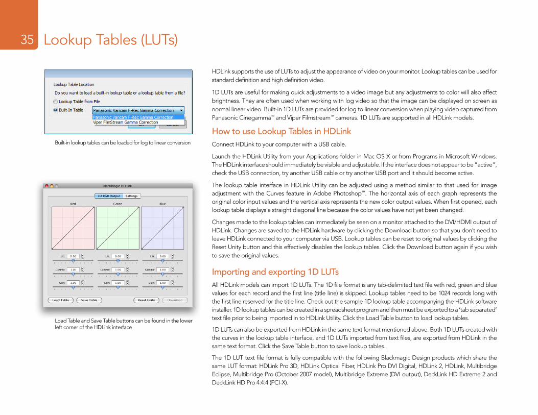
HDLink supports the use of LUTs to adjust the appearance of video on your monitor. Lookup tables can be used for standard definition and high definition video.
1D LUTs are useful for making quick adjustments to a video image but any adjustments to color will also affect brightness. They are often used when working with log video so that the image can be displayed on screen as normal linear video. Built-in 1D LUTs are provided for log to linear conversion when playing video captured from Panasonic Cinegamma™ and Viper Filmstream™ cameras. 1D LUTs are supported in all HDLink models.
How to use Lookup Tables in HDLinkConnect HDLink to your computer with a USB cable.
Launch the HDLink Utility from your Applications folder in Mac OS X or from Programs in Microsoft Windows. The HDLink interface should immediately be visible and adjustable. If the interface does not appear to be “active”, check the USB connection, try another USB cable or try another USB port and it should become active.
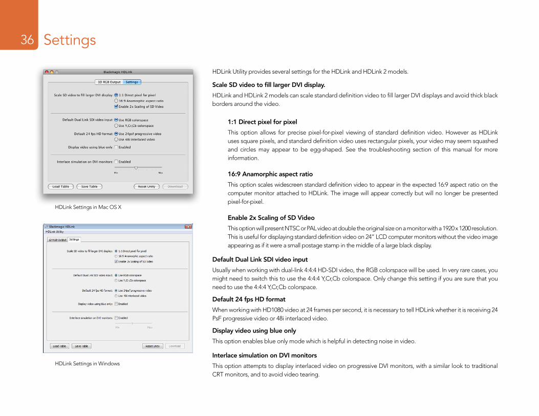
The lookup table interface in HDLink Utility can be adjusted using a method similar to that used for image adjustment with the Curves feature in Adobe Photoshop™. The horizontal axis of each graph represents the original color input values and the vertical axis represents the new color output values. When first opened, each lookup table displays a straight diagonal line because the color values have not yet been changed.
Changes made to the lookup tables can immediately be seen on a monitor attached to the DVI/HDMI output of HDLink. Changes are saved to the HDLink hardware by clicking the Download button so that you don’t need to leave HDLink connected to your computer via USB. Lookup tables can be reset to original values by clicking the Reset Unity button and this effectively disables the lookup tables. Click the Download button again if you wish to save the original values.
Importing and exporting 1D LUTsAll HDLink models can import 1D LUTs. The 1D file format is any tab-delimited text file with red, green and blue values for each record and the first line (title line) is skipped. Lookup tables need to be 1024 records long with the first line reserved for the title line. Check out the sample 1D lookup table accompanying the HDLink software installer. 1D lookup tables can be created in a spreadsheet program and then must be exported to a ‘tab separated’ text file prior to being imported in to HDLink Utility. Click the Load Table button to load lookup tables.
1D LUTs can also be exported from HDLink in the same text format mentioned above. Both 1D LUTs created with the curves in the lookup table interface, and 1D LUTs imported from text files, are exported from HDLink in the same text format. Click the Save Table button to save lookup tables.
The 1D LUT text file format is fully compatible with the following Blackmagic Design products which share the same LUT format: HDLink Pro 3D, HDLink Optical Fiber, HDLink Pro DVI Digital, HDLink 2, HDLink, Multibridge Eclipse, Multibridge Pro (October 2007 model), Multibridge Extreme (DVI output), DeckLink HD Extreme 2 and DeckLink HD Pro 4:4:4 (PCI-X).
Built-in lookup tables can be loaded for log to linear conversion
Load Table and Save Table buttons can be found in the lower left corner of the HDLink interface
Installation36 Settings36
HDLink Settings in Mac OS X
HDLink Settings in Windows
HDLink Utility provides several settings for the HDLink and HDLink 2 models.
Scale SD video to fill larger DVI display.
HDLink and HDLink 2 models can scale standard definition video to fill larger DVI displays and avoid thick black borders around the video.
1:1 Direct pixel for pixel
This option allows for precise pixel-for-pixel viewing of standard definition video. However as HDLink uses square pixels, and standard definition video uses rectangular pixels, your video may seem squashed and circles may appear to be egg-shaped. See the troubleshooting section of this manual for more information.
16:9 Anamorphic aspect ratio
This option scales widescreen standard definition video to appear in the expected 16:9 aspect ratio on the computer monitor attached to HDLink. The image will appear correctly but will no longer be presented pixel-for-pixel.
Enable 2x Scaling of SD Video
This option will present NTSC or PAL video at double the original size on a monitor with a 1920 x 1200 resolution. This is useful for displaying standard definition video on 24” LCD computer monitors without the video image appearing as if it were a small postage stamp in the middle of a large black display.
Default Dual Link SDI video input
Usually when working with dual-link 4:4:4 HD-SDI video, the RGB colorspace will be used. In very rare cases, you might need to switch this to use the 4:4:4 Y,Cr,Cb colorspace. Only change this setting if you are sure that you need to use the 4:4:4 Y,Cr,Cb colorspace.
Default 24 fps HD format
When working with HD1080 video at 24 frames per second, it is necessary to tell HDLink whether it is receiving 24 PsF progressive video or 48i interlaced video.
Display video using blue only
This option enables blue only mode which is helpful in detecting noise in video.
Interlace simulation on DVI monitors
This option attempts to display interlaced video on progressive DVI monitors, with a similar look to traditional CRT monitors, and to avoid video tearing.
Installation37 HDLink and HDLink 237
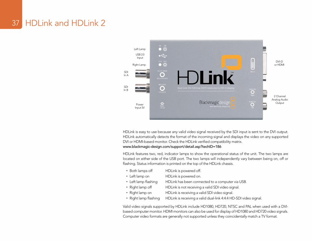
HDLink is easy to use because any valid video signal received by the SDI input is sent to the DVI output. HDLink automatically detects the format of the incoming signal and displays the video on any supported DVI or HDMI-based monitor. Check the HDLink verified compatibility matrix.www.blackmagic-design.com/support/detail.asp?techID=186
HDLink features two, red, indicator lamps to show the operational status of the unit. The two lamps are located on either side of the USB port. The two lamps will independently vary between being on, off or flashing. Status information is printed on the top of the HDLink chassis.
� Both lamps off HDLink is powered off. � Left lamp on HDLink is powered on. � Left lamp flashing HDLink has been connected to a computer via USB. � Right lamp off HDLink is not receiving a valid SDI video signal. � Right lamp on HDLink is receiving a valid SDI video signal. � Right lamp flashing HDLink is receiving a valid dual-link 4:4:4 HD-SDI video signal.
Valid video signals supported by HDLink include HD1080, HD720, NTSC and PAL when used with a DVI-based computer monitor. HDMI monitors can also be used for display of HD1080 and HD720 video signals. Computer video formats are generally not supported unless they coincidentally match a TV format.
2 Channel Analog Audio
Output
DVI-D or HDMI
SDI In A
SDI In B
USB 2.0 Input
Power Input 5V
Left Lamp
Right Lamp
Installation38 HDLink and HDLink 238
HDLink is preconfigured for you, requiring no initial setup to connect. Your HDLink will simply run without changing any settings, however, if you would like to update the firmware, modify settings or load custom gamma tables, then use the HDLink Utility software. This can be downloaded from the Blackmagic Design web site support page. Check www.blackmagic-design.com/support/
1D lookup tables can be applied to the DVI/HDMI output of HDLink.
DVI-D monitors are shown in most of the connection diagrams shown for this HDLink model. An HDMI display can be used in all cases except for standard definition monitoring. HDMI displays are best for use with HD720p50 as most DVI displays do not support this format. The included DVI-to-HDMI adapter can be used to attach an HDMI display to the DVI output of HDLink. Third party DVI to HDMI adapters can also be used if your HDLink shipped before the addition of HDMI support.
HDLink provides two SDI inputs which can be used for standard definition SDI, HD-SDI 4:2:2 and Dual Link HD-SDI 4:4:4 as shown in the connection diagrams of this manual.
The consumer level analog audio outputs are fully compatible with a wide range of consumer HiFi equipment and are perfect for monitoring of stereo audio.
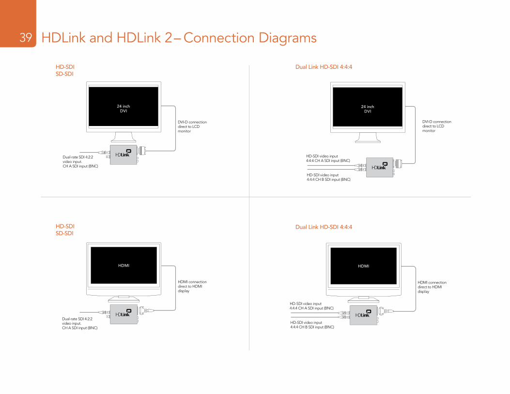
Installation39 HDLink and HDLink 2– Connection Diagrams39
HD-SDISD-SDI
24 inchDVI
DVI-D connection direct to LCD monitor
Dual-rate SDI 4:2:2 video input. CH A SDI input (BNC)
Dual Link HD-SDI 4:4:4
24 inchDVI
HD-SDI video input 4:4:4 CH A SDI input (BNC)
HD-SDI video input 4:4:4 CH B SDI input (BNC)
DVI-D connection direct to LCD monitor
HDMI
HDMI connection direct to HDMI display
HD-SDISD-SDI
Dual-rate SDI 4:2:2 video input. CH A SDI input (BNC)
HDMI
HDMI connection direct to HDMI display
Dual-rate SDI 4:2:2 video input. CH A SDI input (BNC)
Dual Link HD-SDI 4:4:4
24 inchDVI
HD-SDI video input 4:4:4 CH A SDI input (BNC)
HD-SDI video input 4:4:4 CH B SDI input (BNC)
Troubleshooting40 Troubleshooting40
Why can’t I see standard definition on my HDMI-based TV?The HDLink and HDLink 2 models were originally designed for use with DVI displays before HDMI was widely available. HDMI support was subsequently added with a HDLink software update which upgraded the firmware in both the HDLink and HDLink 2 models. This firmware update exclusively supported high definition video formats and not standard definition. If you need to monitor standard definition with these models of HDLink, you will need to use a DVI-based monitor. If your DVI monitor supports 1920 x 1200 resolution, you may wish to use the Enable 2x Scaling of SD Video setting in order to mostly fill the display with your video. This will minimize the black borders around your standard definition video. Blackmagic Design has newer HDLink models which support standard definition via HDMI.
Why can’t I hear audio on my HDMI TV?The original HDLink and HDLink 2 were originally designed for use with DVI displays and the DVI standard does not support audio. That is why stereo, analog, RCA ports are provided on the HDLink for low cost, 2-channel monitoring of SDI audio. HDMI support was subsequently added with a HDLink software update which upgraded the firmware in both the HDLink and HDLink 2 models. This firmware update exclusively supported high definition video formats via HDMI but audio must still be monitored via the analog outputs. Analog audio can be connected to an amplifier for audio monitoring and some HDMI-based TVs also provide analog, RCA audio inputs which makes it even easier to connect the HDMI video and analog audio directly to the TV. Blackmagic Design has newer HDLink models which support 2-channel audio monitoring via HDMI.
Why can’t I use a 30” DVI monitor?HDLink and HDLink 2 models connect to DVI-based monitors via a single-link DVI-D connection. This includes LCD computer monitors with a resolution of up to 1920 x 1200 pixels. Larger monitors, such as 30” LCD computer monitors, support higher resolutions but require a dual-link DVI-D connection. Blackmagic Design has newer HDLink models which support 30” dual-link DVI-D LCD computer monitors as well as smaller single-link DVI-D monitors.
Troubleshooting41 Troubleshooting41
Some or all video formats fail to work with a DVI display
The following information relates to the use of DVI-D displays with HDLink and HDLink 2. It does not apply to HDMI displays used with HDLink.
1. Check the DVI-D cableDVI-D cables are usually reliable but there are many different brands and lengths and it is wise to test with another cable if you have poor video or no video output. Try using a good quality cable which is of a standard length, i.e. around 6 feet or 2 meters. While long DVI-D cables are available, some work better than others and so we recommend the use of the standard length cables, i.e. around 6 feet or 2 meters.
2. Check the specifications of your display.HDLink supports single-link DVI-D displays. It does not support dual-link DVI-D displays such as the Apple Cinema HD 30” display. Blackmagic Design has newer HDLink models which support both single-link and dual-link DVI-D displays.
Next, check that your DVI-D display has an adequate resolution to support the video formats with which you work. HDLink is designed to display video pixel-for-pixel and does not scale down to fit lower resolution displays. HDLink supports video formats including:
� NTSC, 720 x 486 pixels � PAL, 720 x 576 pixels � HDTV 720p, 1280 x 720 pixels � HDTV 1080, 1920 x 1080
Numerous 23” and 24” DVI-D displays support 1920 x 1200 resolution and these are excellent for use with HDTV 1080 material. The resolution of these displays is high enough for HDLink to display NTSC and PAL at x2 resolution. This is nice as standard definition video almost fills these displays at x2 resolution.
If your display is of a lower resolution than the video format with which you are working, your video will not display correctly. For example, you cannot output 1920 x 1080 video to a 1280 x 720 display.
Similarly, a 1280 x 720 display is more than adequate to display NTSC and PAL video but it will not support x2 display of these formats.
Troubleshooting42 Troubleshooting42
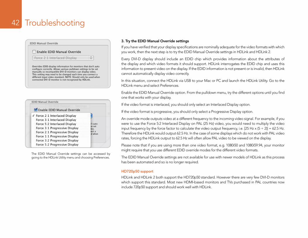
3. Try the EDID Manual Override settings
If you have verified that your display specifications are nominally adequate for the video formats with which you work, then the next step is to try the EDID Manual Override settings in HDLink and HDLink 2.
Every DVI-D display should include an EDID chip which provides information about the attributes of the display and which video formats it should support. HDLink interrogates the EDID chip and uses this information to present video on the display. If the EDID information is not present or is invalid, then HDLink cannot automatically display video correctly.
In this situation, connect the HDLink via USB to your Mac or PC and launch the HDLink Utility. Go to the HDLink menu and select Preferences.
Enable the EDID Manual Override option. From the pulldown menu, try the different options until you find one that works with your display.
If the video format is interlaced, you should only select an Interlaced Display option.
If the video format is progressive, you should only select a Progressive Display option.
An override mode outputs video at a different frequency to the incoming video signal. For example, if you were to use the Force 5:2 Interlaced Display on PAL (25 Hz) video, you would need to multiply the video input frequency by the force factor to calculate the video output frequency, i.e. [25 Hz x (5 ÷ 2)] = 62.5 Hz. Therefore the HDLink would output 62.5 Hz. In the case of some displays which do not work with PAL video rates, forcing the HDLink output to 62.5 Hz will often allow PAL video to be viewed on the display.
Please note that if you are using more than one video format, e.g. 1080i50 and 1080i59.94, your monitor might require that you use different EDID override modes for the different video formats.
The EDID Manual Override settings are not available for use with newer models of HDLink as this process has been automated and so is no longer required.
HD720p50 support
HDLink and HDLink 2 both support the HD720p50 standard. However there are very few DVI-D monitors which support this standard. Most new HDMI-based monitors and TVs purchased in PAL countries now include 720p50 support and should work well with HDLink.
The EDID Manual Override settings can be accessed by going to the HDLink Utility menu and choosing Preferences.
Troubleshooting43 Troubleshooting43
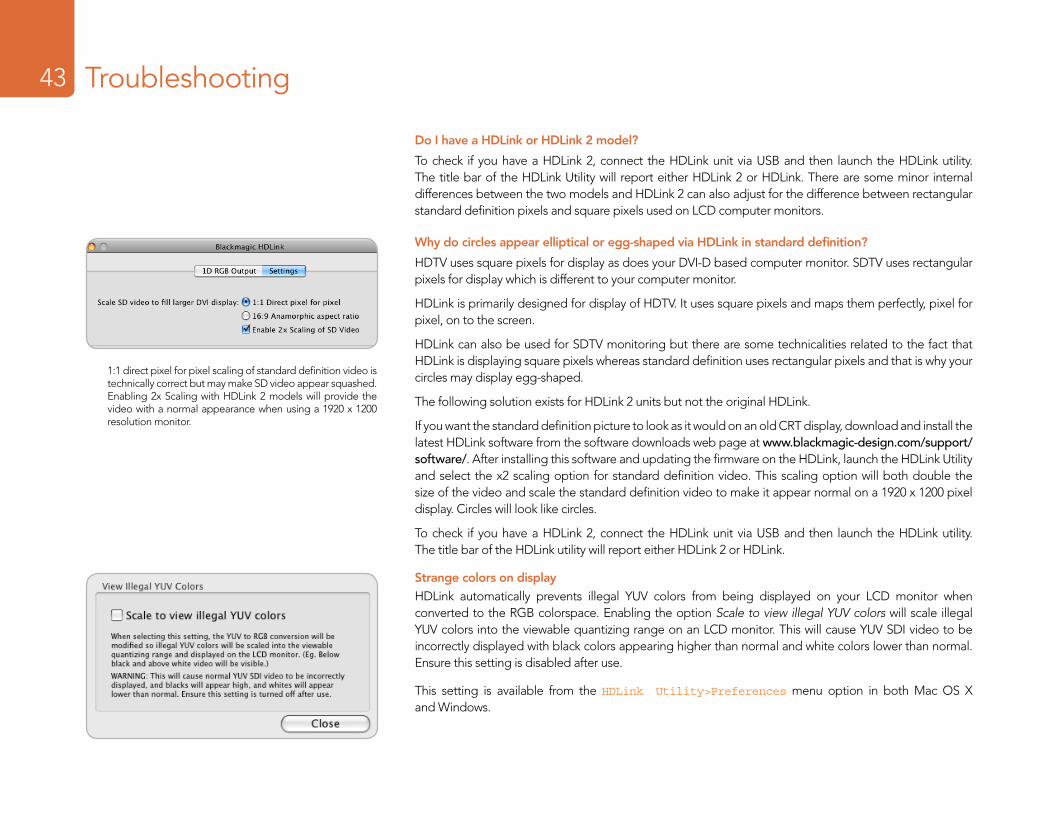
Do I have a HDLink or HDLink 2 model?
To check if you have a HDLink 2, connect the HDLink unit via USB and then launch the HDLink utility. The title bar of the HDLink Utility will report either HDLink 2 or HDLink. There are some minor internal differences between the two models and HDLink 2 can also adjust for the difference between rectangular standard definition pixels and square pixels used on LCD computer monitors.
Why do circles appear elliptical or egg-shaped via HDLink in standard definition?
HDTV uses square pixels for display as does your DVI-D based computer monitor. SDTV uses rectangular pixels for display which is different to your computer monitor.
HDLink is primarily designed for display of HDTV. It uses square pixels and maps them perfectly, pixel for pixel, on to the screen.
HDLink can also be used for SDTV monitoring but there are some technicalities related to the fact that HDLink is displaying square pixels whereas standard definition uses rectangular pixels and that is why your circles may display egg-shaped.
The following solution exists for HDLink 2 units but not the original HDLink.
If you want the standard definition picture to look as it would on an old CRT display, download and install the latest HDLink software from the software downloads web page at www.blackmagic-design.com/support/software/. After installing this software and updating the firmware on the HDLink, launch the HDLink Utility and select the x2 scaling option for standard definition video. This scaling option will both double the size of the video and scale the standard definition video to make it appear normal on a 1920 x 1200 pixel display. Circles will look like circles.
To check if you have a HDLink 2, connect the HDLink unit via USB and then launch the HDLink utility. The title bar of the HDLink utility will report either HDLink 2 or HDLink.
Strange colors on displayHDLink automatically prevents illegal YUV colors from being displayed on your LCD monitor when converted to the RGB colorspace. Enabling the option Scale to view illegal YUV colors will scale illegal YUV colors into the viewable quantizing range on an LCD monitor. This will cause YUV SDI video to be incorrectly displayed with black colors appearing higher than normal and white colors lower than normal. Ensure this setting is disabled after use.
This setting is available from the HDLink Utility>Preferences menu option in both Mac OS X and Windows.
1:1 direct pixel for pixel scaling of standard definition video is technically correct but may make SD video appear squashed. Enabling 2x Scaling with HDLink 2 models will provide the video with a normal appearance when using a 1920 x 1200 resolution monitor.

Warranty
44
Warranty45
3 Year Limited WarrantyBlackmagic Design warrants that this product will be free from defects in materials and workmanship for a period of 36 months from the date of purchase excluding user-servicable fiber optic modules which will be free from defects in materials and workmanship for a period of 12 months from the date of purchase. If a product proves to be defective during this warranty period, Blackmagic Design, at its option, either will repair the defective product without charge for parts and labor, or will provide a replacement in exchange for the defective product.
In order to obtain service under this warranty, you the Customer, must notify Blackmagic Design of the defect before the expiration of the warranty period and make suitable arrangements for the performance of service. The Customer shall be responsible for packaging and shipping the defective product to a designated service center nominated by Blackmagic Design, with shipping charges pre paid. Customer shall be responsible for paying all shipping changes, insurance, duties, taxes, and any other charges for products returned to us for any reason.
This warranty shall not apply to any defect, failure or damage caused by improper use or improper or inadequate maintenance and care. Blackmagic Design shall not be obligated to furnish service under this warranty: a) to repair damage resulting from attempts by personal other than Blackmagic Design representatives to install, repair or service the product, b) to repair damage resulting from improper use or connection to incompatible equipment, c) to repair any damage or malfunction caused by the use of non Blackmagic Design parts or supplies, or d) to service a product that has been modified or integrated with other products when the effect of such a modification or integration increases the time or difficulty of servicing the product. THIS WARRANTY IS GIVEN BY BLACKMAGIC DESIGN IN LIEU OF ANY OTHER WARRANTIES, EXPRESS OR IMPLIED. BLACKMAGIC DESIGN AND ITS VENDORS DISCLAIM ANY IMPLIED WARRANTIES OF MERCHANTABILITY OR FITNESS FOR A PARTICULAR PURPOSE. BLACKMAGIC DESIGN’S RESPONSIBILITY TO REPAIR OR REPLACE DEFECTIVE PRODUCTS IS THE WHOLE AND EXCLUSIVE REMEDY PROVIDED TO THE CUSTOMER FOR ANY INDIRECT, SPECIAL, INCIDENTAL OR CONSEQUENTIAL DAMAGES IRRESPECTIVE OF WHETHER BLACKMAGIC DESIGN OR THE VENDOR HAS ADVANCE NOTICE OF THE POSSIBILITY OF SUCH DAMAGES. BLACKMAGIC DESIGN IS NOT LIABLE FOR ANY ILLEGAL USE OF EQUIPMENT BY CUSTOMER. BLACKMAGIC IS NOT LIABLE FOR ANY DAMAGES RESULTING FROM USE OF THIS PRODUCT. USER OPERATES THIS PRODUCT AT OWN RISK.
Copyright 2010 Blackmagic Design. All rights reserved. ‘Blackmagic Design’, ‘DeckLink’, ‘HDLink’, ‘Workgroup Videohub’, ‘ Videohub’, ‘DeckLink’, ‘Intensity’ and ‘Leading the creative video revolution’ are registered trademarks in the US and other countries. All other company and product names may be trade marks of their respective companies with which they are associated.