Embed Size (px)
Citation preview

OPERATION MANUAL
FOR PEMSERTER® SERIES P3 PRESS
PennEngineering® 5190 OLD EASTON ROAD
DANBORO, PENNSYLVANIA 18916
1-800-523-5321 • 1-215-766-8853
Document No. 8008891
Revision L JUN 2019
1
Read Manual Before Operating Press!
FOREWORD Thank you for purchasing a PEMSERTER® SERIES P3™ PRESS. With the proper care and
maintenance, your press will install millions of fasteners safely, quickly and with consistent
quality.
The PRESS is covered with a one (1) year warranty.
Should any questions or problems arise concerning your SERIES P3™ PRESS contact
PennEngineering® Service department. The toll free number is 800-523-5321 (in North
America) or 215-766-8853.
Set-up, Training and Repair Service is available to you as long as you are the owner of the press.
Free telephone instruction and service are also available for the lifetime of your press by calling
the PennEngineering® Service Department.
SHIPPING DAMAGE
The PEMSERTER® SERIES P3™ press has been shipped to you packaged to withstand
normal handling during transit. Upon receipt, the unit should be checked for any damage
that may have occurred during shipment due to improper handling. Should any damage
be found, immediately notify the PennEngineering® Service Department.
PEMSERTER® SERIES P3™ PNEUMATIC PRESS
The PEMSERTER® SERIES P3™ press is shipped ready to operate and complete with the
standard tooling accessories.
• Metric press kit (P/N 981820003) contains punches and anvils to install nuts (S, CLS and
CLA) ranging from M2 thru M5 thread sizes and studs (FH, FHS and FHA up to 12mm in
length) ranging from M2.5 thru M5 thread sizes.
• Unified press kit (P/N 981820002) contains punches and anvils to install nuts (S, CLS and
CLA) ranging from #2-56 thru #10-32 thread sizes and studs (FH, FHS and FHA up to 1/2”
in length) ranging from #2-56 thru #10-32 thread sizes.
• The Series P3™ press can be bench-mounted. The backside of the yoke has two (2)
predrilled and tapped holes for bench mounting. Mounting bracket is included (P/N
981820007).
SPECIFICATIONS:
Ram Force ................................................................400 to 5,000 lbs. (1.8 to 22.2 kN)
Air Requirements ................................90 to 100 PSI (6 to 7 BAR)
Air Line ................................................................½” (12mm) I.D. Minimum line flow
Throat Depth ................................................................3” (7.6 cm)
Weight ................................................................10 lbs. (4.6 kg)
Length ................................................................16” (40.6 cm)
Yoke Depth ................................................................6.2” (15.8 cm)
Air Consumption ................................Approx. 15 cu in (.25 liters) per cycle
2
Please read and follow the safety precautions listed below.
SAFETY PRECAUTIONS
♦ Always use safety goggles when operating or maintaining the press.
♦ Ear Protection is recommended.
♦ Before using the press, make sure that a shutoff device has been fitted on the air supply line
and the location is easily accessible, so that the air supply to the press can be shut off in an
emergency.
♦ Check the air hose and fittings regularly for wear.
♦ Use only approved parts for maintenance and repairs.
♦ Do not use chipped, cracked or damaged accessories and tools.
♦ Attach air line securely.
♦ Keep body parts away from moving parts.
♦ Never wear jewelry, loose clothing or anything that could get caught in moving parts.
♦ If a new user is operating the press, be sure these instructions are readily available.
♦ Do not use the press in any way other than for its intended purposes.
♦ Do not modify the press.
WARRANTY
PennEngineering® warrants that this product, when correctly used according to directions and
under normal operating conditions, will be free from defects in material and workmanship for a
period of one (1) year from the date of purchase.
This warranty shall not apply to any product which has been altered, changed or repaired, normal
maintenance excluded, except as authorized by PennEngineering®. This warranty shall not apply
to any product that has been subject to misuse, negligence or accident.
The purchaser’s exclusive and sole remedy shall be limited to repair, modification or
replacement at the discretion of PennEngineering®. In no event shall PennEngineering® be liable
for the cost of any indirect or consequential damage. In no case shall PennEngineering®’s
liability exceed the purchase price of the product.
This warranty is exclusive and in lieu of all other warranties. No oral or written information by
PennEngineering®, its employees, representatives, distributors or agents shall increase the scope
of the above warranty or create any new warranty.
3
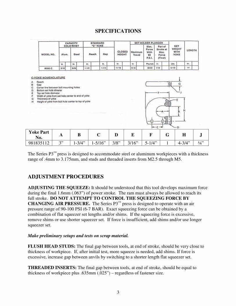
SPECIFICATIONS
Yoke Part
No. A B C D E F G H J
981835112 3” 1-3/4” 1-5/16” 3/8” 3/16” 5-1/4” 1 4-3/4” ¼”
The Series P3™ press is designed to accommodate steel or aluminum workpieces with a thickness
range of .4mm to 3.175mm, and studs and threaded inserts from M2.5 through M5.
ADJUSTMENT PROCEDURES
ADJUSTING THE SQUEEZE: It should be understood that this tool develops maximum force
during the final 1.6mm (.063”) of power stroke. The ram must always be allowed to reach its
full stroke. DO NOT ATTEMPT TO CONTROL THE SQUEEZING FORCE BY
CHANGING AIR PRESSURE. The Series P3™ press is designed to operate with an air
pressure range of 90-100 PSI (6-7 BAR). Exact squeezing force can be obtained by a
combination of flat squeezer set lengths and/or shims. If the squeezing force is excessive,
remove shims or use shorter squeezer set. If force is insufficient, add shims and/or use longer
squeezer set.
Make preliminary setups and tests on scrap material.
FLUSH HEAD STUDS: The final gap between tools, at end of stroke, should be very close to
thickness of workpiece. If, after initial test, more squeeze is needed, add shims. If force is
excessive, increase gap between anvils by switching to a shorter length flat squeezer set.
THREADED INSERTS: The final gap between tools, at end of stroke, should be equal to
thickness of workpiece plus .635mm (.025”) – regardless of fastener size.

4
IDENTIFICATION DRAWING

5
IDENTIFICATION DRAWING BOM:
ITEM Qty PEM Part No. Description ITEM Qty PEM Part No. Description
1 1 981835112 YOKE, STANDARD 27 1 982035103 FORK,6000A/6000C 05
2 1 982035142 SPRING,SET HOLDER 2 28 1 982035126 ASM,PISTON
3 1 982035119 SET HOLDER STANDARD 29 2 9800391924 PISTON CUP G/P
4 2 9800392003 NUT,YOKE BOLT 30 2 982035141 PLATE, PISTON LEATH
5 2 982035107 YOKE, PLATE 3C/6C 0 31 1 982035111 SHAFT, PISTON 6000C
6 2 982035121 WEDGE, GUIDE 32 2 982035149 SNAP RING 6A/6C 230
7 2 982035125 ASM,PLATE ROLLER 33 1 982035134 ORING,SPACER INNER
7a 4 8025104 THRUST WASHER 34 1 982035108 SPACER, CLYINDER 05
7b 2 8025105 ROLLER, OUTER 35 1 982035135 ORING,SPACER OUTER
7c 2 982035162 SHAFT, ROLLER 36
7d 40 8025106 NEEDLE ROLLERS 37 1 982035155 PISTON REAR
8 1 982035100 ASM, PLATE ROLLER 1 38 1
9 2 9800392002 BOLT,YOKE 6C 39 1 982035140 NUT, LOCK 3/8-24 18
10 1 982035115 SET LEVER 3C/6C 40 1 9800391925 GASKET CYL HD G/P 1
11 1 982035147 SHAFT, LEVER BEARING 41 1 982035130 ASM,CYLINDER HD SAF
12 1 982035127 ASM,LEVER BEARING 42 6 982035136 SCREW, CLYINDER HEA
12a 1 982035164 OUTER ROLLER 43 1 982035138 SCREW, LEVER ARM
12b 1 982035165 INNER ROLLER 44 1 982035145 SPRING,THROTTLE LEV
12c 25 982035166 NEEDLE ROLLERS 45 1 982035123 LEVER, ARM
13 1 982035129 ASM,LEVER COMPLETE 46 1 982035109 VALVE
14 1 982035124 THROTTLE, LEVER G.P 47 1 982035131 ORING,VALVE
15 1 982035132 ORING,SWIVEL BOLT 1 48 1 982035146 SPRING,VALVETLE LEV
16 1 982035105 WASHER, SHAFT 49 1 982035168 O' RING BUSHING
17 1 982035139 SCREW, ROLLER GUARD 50 1 982035117 BUSHING, VALVE SAFE
18 1 982035122 GUARD, ROLLER 3C/6C 51 1 982035102 CYLINDER HEAD BARE
19 1 982035106 SPACER,GUARD BLOCK 52
20 1 9800392004 SHAFT,LEVER ECCENTR 53 1 982035132 ORING,SWIVEL BOLT
21 1 982035103 FORK,6000A/6000C 54 1 982035113 SWIVEL
22 1 982035167 HOUSING, CYLINDER, BARE 55 1 982035133 ORING,SWIVEL NUT
23 2 982035143 SPRING,INNER 56 1 982035110 NUT,SWIVEL
24 2 982035144 SPRING,OUTER 57 1 982035112 ELBOW, INLET 1/4 PI
25 1 982035114 WEDGE /6000C 58 1 982035099 ASM, SWIVEL
26 1 982035148 PIN, FORK 3000A/300 59 1 982035128 ASSY, CYL HEAD W/O
SWIVEL
6
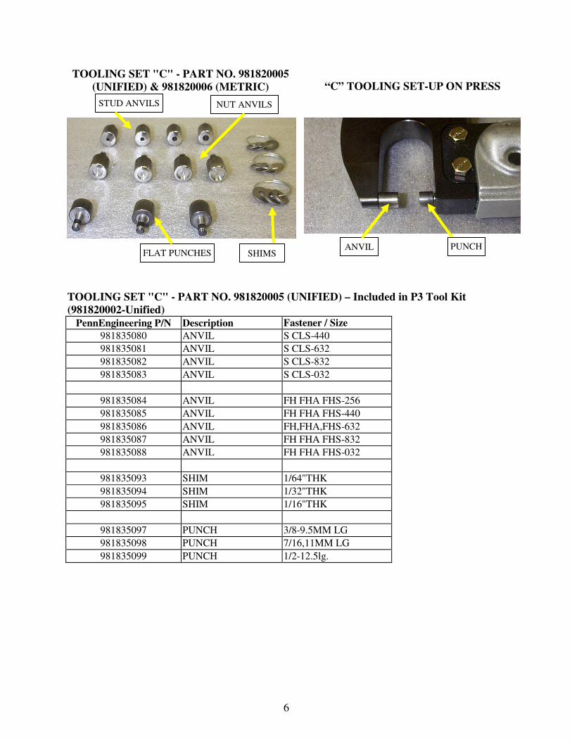
TOOLING SET "C" - PART NO. 981820005
(UNIFIED) & 981820006 (METRIC)
“C” TOOLING SET-UP ON PRESS
TOOLING SET "C" - PART NO. 981820005 (UNIFIED) – Included in P3 Tool Kit
(981820002-Unified)
PennEngineering P/N Description Fastener / Size
981835080 ANVIL S CLS-440
981835081 ANVIL S CLS-632
981835082 ANVIL S CLS-832
981835083 ANVIL S CLS-032
981835084 ANVIL FH FHA FHS-256
981835085 ANVIL FH FHA FHS-440
981835086 ANVIL FH,FHA,FHS-632
981835087 ANVIL FH FHA FHS-832
981835088 ANVIL FH FHA FHS-032
981835093 SHIM 1/64"THK
981835094 SHIM 1/32"THK
981835095 SHIM 1/16"THK
981835097 PUNCH 3/8-9.5MM LG
981835098 PUNCH 7/16,11MM LG
981835099 PUNCH 1/2-12.5lg.
ANVIL FLAT PUNCHES
NUT ANVILS STUD ANVILS
PUNCH SHIMS
7
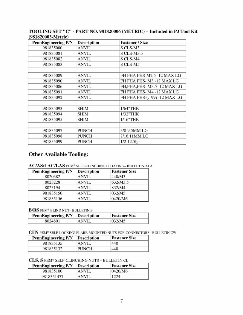
TOOLING SET "C" - PART NO. 981820006 (METRIC) – Included in P3 Tool Kit
(981820003-Metric)
PennEngineering P/N Description Fastener / Size
981835080 ANVIL S CLS-M3
981835081 ANVIL S CLS-M3.5
981835082 ANVIL S CLS-M4
981835083 ANVIL S CLS-M5
981835089 ANVIL FH FHA FHS-M2.5 -12 MAX LG
981835090 ANVIL FH FHA FHS- M3 -12 MAX LG
981835086 ANVIL FH,FHA,FHS- M3.5 -12 MAX LG
981835091 ANVIL FH FHA FHS- M4 -12 MAX LG
981835092 ANVIL FH FHA FHS-(.199) -12 MAX LG
981835093 SHIM 1/64"THK
981835094 SHIM 1/32"THK
981835095 SHIM 1/16"THK
981835097 PUNCH 3/8-9.5MM LG
981835098 PUNCH 7/16,11MM LG
981835099 PUNCH 1/2-12.5lg.
Other Available Tooling:
AC/AS/LAC/LAS PEM® SELF-CLINCHING FLOATING– BULLETIN ALA
PennEngineering P/N Description Fastener Size
8020382 ANVIL 440/M3
8023228 ANVIL 632/M3.5
8023194 ANVIL 832/M4
981835150 ANVIL 032/M5
981835156 ANVIL 0420/M6
B/BS PEM® BLIND NUT– BULLETIN B
PennEngineering P/N Description Fastener Size
8024801 ANVIL 032/M5
CFN PEM® SELF-LOCKING FLARE-MOUNTED NUTS FOR CONNECTORS– BULLETIN CW
PennEngineering P/N Description Fastener Size
981835135 ANVIL 440
981835132 PUNCH 440
CLS, S PEM® SELF-CLINCHING NUTS – BULLETIN CL
PennEngineering P/N Description Fastener Size
981835100 ANVIL 0420/M6
9818351477 ANVIL 1224
8
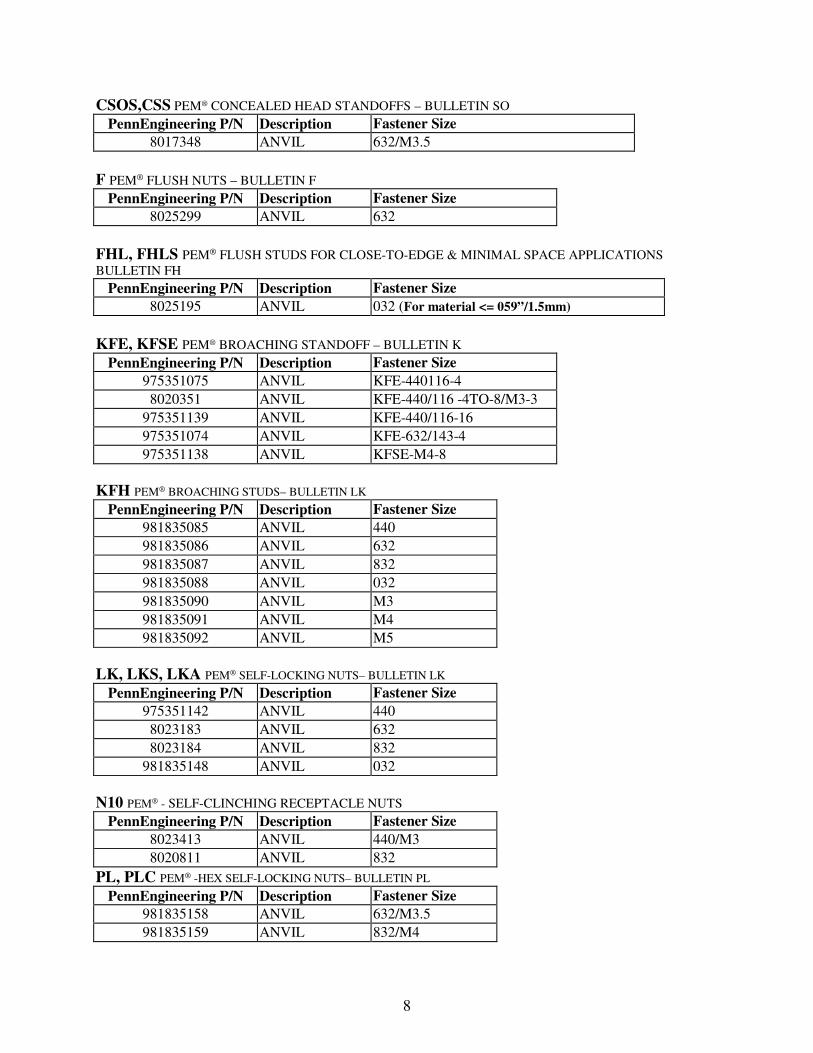
CSOS,CSS PEM® CONCEALED HEAD STANDOFFS – BULLETIN SO
PennEngineering P/N Description Fastener Size
8017348 ANVIL 632/M3.5
F PEM® FLUSH NUTS – BULLETIN F
PennEngineering P/N Description Fastener Size
8025299 ANVIL 632
FHL, FHLS PEM® FLUSH STUDS FOR CLOSE-TO-EDGE & MINIMAL SPACE APPLICATIONS
BULLETIN FH
PennEngineering P/N Description Fastener Size
8025195 ANVIL 032 (For material <= 059”/1.5mm)
KFE, KFSE PEM® BROACHING STANDOFF – BULLETIN K
PennEngineering P/N Description Fastener Size
975351075 ANVIL KFE-440116-4
8020351 ANVIL KFE-440/116 -4TO-8/M3-3
975351139 ANVIL KFE-440/116-16
975351074 ANVIL KFE-632/143-4
975351138 ANVIL KFSE-M4-8
KFH PEM® BROACHING STUDS– BULLETIN LK
PennEngineering P/N Description Fastener Size
981835085 ANVIL 440
981835086 ANVIL 632
981835087 ANVIL 832
981835088 ANVIL 032
981835090 ANVIL M3
981835091 ANVIL M4
981835092 ANVIL M5
LK, LKS, LKA PEM® SELF-LOCKING NUTS– BULLETIN LK
PennEngineering P/N Description Fastener Size
975351142 ANVIL 440
8023183 ANVIL 632
8023184 ANVIL 832
981835148 ANVIL 032
N10 PEM® - SELF-CLINCHING RECEPTACLE NUTS
PennEngineering P/N Description Fastener Size
8023413 ANVIL 440/M3
8020811 ANVIL 832
PL, PLC PEM® -HEX SELF-LOCKING NUTS– BULLETIN PL
PennEngineering P/N Description Fastener Size
981835158 ANVIL 632/M3.5
981835159 ANVIL 832/M4
9
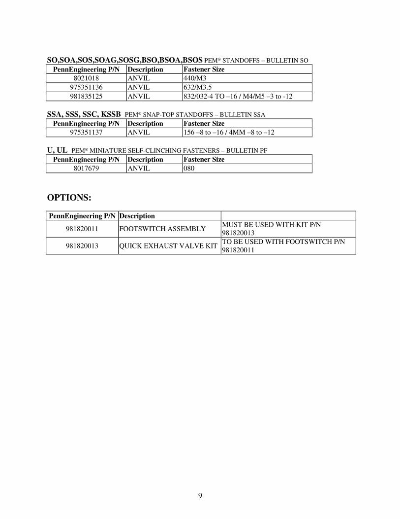
SO,SOA,SOS,SOAG,SOSG,BSO,BSOA,BSOS PEM® STANDOFFS – BULLETIN SO
PennEngineering P/N Description Fastener Size
8021018 ANVIL 440/M3
975351136 ANVIL 632/M3.5
981835125 ANVIL 832/032-4 TO –16 / M4/M5 –3 to -12
SSA, SSS, SSC, KSSB PEM® SNAP-TOP STANDOFFS – BULLETIN SSA
PennEngineering P/N Description Fastener Size
975351137 ANVIL 156 –8 to –16 / 4MM –8 to –12
U, UL PEM® MINIATURE SELF-CLINCHING FASTENERS – BULLETIN PF
PennEngineering P/N Description Fastener Size
8017679 ANVIL 080
OPTIONS:
PennEngineering P/N Description
981820011 FOOTSWITCH ASSEMBLY MUST BE USED WITH KIT P/N
981820013
981820013 QUICK EXHAUST VALVE KIT TO BE USED WITH FOOTSWITCH P/N
981820011