Embed Size (px)
Citation preview

EMISSION MONITORING SYSTEMS
Operation Manual
Flue Gas Analyzer Spectra 2000 Read carefully before putting into service!
G:\TECH-DOC\S 2000\ENG\S2000_ENG.
MRU Nr. 58301 ENGLISCH
TÜV By Rg G 208

MRU GmbH Operating manual Spectra 2000
2
1 Contents
1 Contents 2
2 Notice 7
3 Introduction 8
3.1 The Flue Gas Analyzer Spectra 2000................................................................ 8
3.2 The Company MRU GmbH................................................................................. 8
3.3 Important Instructions regarding the Operation Manual ................................ 8
4 Safety Regulations 9
4.1 Safety Instructions................................................................................................ 9
4.2 Specific Safety Instructions .................................................................................. 9
5 Functional Description 10
5.1 Main Menus of Spectra 2000 ........................................................................... 11
5.2 Device Illustrations........................................................................................... 12 5.2.1 Perspectiv View ....................................................................................... 12 5.2.2 Connection plate...................................................................................... 12 5.2.3 Probe ....................................................................................................... 13 5.2.4 Insert of the condensate trap ................................................................... 13 5.2.5 Keyboard ................................................................................................. 14
5.3 Operation of device.......................................................................................... 14 5.3.1 The keyboard ........................................................................................... 14 5.3.2 Power supply ........................................................................................... 15
6 Operation 16
6.1 Preparation for Measurement.......................................................................... 16 6.1.1 Getting Started......................................................................................... 16 6.1.2 Calibration Phase..................................................................................... 16
6.2 Measurements .................................................................................................. 18 6.2.1 Pressure measurement (option) .............................................................. 18
6.2.1.1 Pressure measurement before flue gas measurement ...........................18 6.2.1.2 Pressure measurement when saving the measured values ...................19 6.2.1.3 Pressure values in data storage ................................................................19 6.2.1.4 Print pressure values..................................................................................19
6.2.2 Flue gas measurement ............................................................................ 20 6.2.2.1 Temporary change of CO cut-off limit .......................................................21 6.2.2.2 Save measurement.....................................................................................22 6.2.2.3 Input of boiler temperature, soot values and oil derivative ......................23 6.2.2.4 Four-window-row when saving ..................................................................24 6.2.2.5 Customer search and customer new entry when saving.........................25 6.2.2.6 Temporary buffer ........................................................................................26 6.2.2.7 Chimney draft respectively fine draft measurement ................................27

MRU GmbH Operating manual Spectra 2000
3
6.2.3 Huge indication of the measured values.................................................. 27 6.2.4 Fuel selection / Measurement program selection .................................... 28 6.2.5 Annular-gap check................................................................................... 29 6.2.6 View last values ....................................................................................... 30 6.2.7 Recalibration............................................................................................ 30
6.3 Customer administration ................................................................................. 31 6.3.1 Customer selection / customer search..................................................... 32 6.3.2 Customer data base................................................................................. 34
6.3.2.1 Customer new entry....................................................................................34 6.3.2.2 Customer modifications ..............................................................................35 6.3.2.3 Customer deletion.......................................................................................35
6.3.3 Customers memory occupation ............................................................... 36 6.3.4 Deletion of all saved customers ............................................................... 36 6.3.5 Transmission of customers from the PC.................................................. 37
6.4 Data Administration ......................................................................................... 39 6.4.1 View stored data ...................................................................................... 39
6.4.1.1 Data search.................................................................................................40 6.4.1.2 Four views of a measuring data block ......................................................40 6.4.1.3 Deletion of a measuring data block...........................................................41
6.4.2 Measurement memory occupation........................................................... 41 6.4.3 Deletion of all saved measuring data blocks............................................ 42 6.4.4 Transmission of measuring data to PC.................................................... 42
6.5 EXTRA / Device configurations....................................................................... 44 6.5.1 Fuel type chart / User definable fuel types / Fuel type pre-selection........ 44 6.5.2 Configure measurement programs (name, CO-limit, printout, indication) 45 6.5.3 Set Date and time.................................................................................... 48 6.5.4 Settings.................................................................................................... 49 6.5.5 Change the current language .................................................................. 50 6.5.6 Service values ......................................................................................... 51 6.5.7 Adjustment............................................................................................... 51 6.5.8 Illumination............................................................................................... 52
6.6 Input of text ....................................................................................................... 52
6.7 Printing procedure with the Infrared-printer HP 82240B(option) ................. 53
6.8 Switch Spectra 2000 On / Off........................................................................... 55 6.8.1 Switch On /Off with main supply is impossible......................................... 55 6.8.2 Switch On / Off with battery operation...................................................... 55
6.8.2.1 Switch on .....................................................................................................55 6.8.2.2 Manual switch Off .......................................................................................55 6.8.2.3 Manual switch off in case of emergency...................................................56 6.8.2.4 Automatically switch off..............................................................................56
7 Battery maintenance (charge and conditioning) 56
7.1 Charge............................................................................................................... 57
7.2 Discharge.......................................................................................................... 58

MRU GmbH Operating manual Spectra 2000
4
7.3 Conditioning ..................................................................................................... 58
7.4 Compensation Charge (Trickle Charge) ......................................................... 59
8 AUX input (option) 60
8.1 Connection thermo couple .............................................................................. 60
8.2 Connection sensor with 0 – 10 V signal ......................................................... 60
8.3 Connection sensor wíth 4-20 mA signal........................................................ 60
8.4 Adjustment of the Aux input ........................................................................... 61
9 Device heating 63
9.1 Adjustment of operational temperature ......................................................... 63
9.2 Prevention of condensate inside the device.................................................. 64
10 Calculation basis 65
10.1 Analysis and calculation.................................................................................. 65 10.1.1 Formula of Siegert ................................................................................... 66
11 Technical specifications 67
12 Storage 69
12.1 Operational and storage temperature............................................................. 69
13 Errors 70
13.1 Error diagnosis regarding the measuring device.......................................... 70
13.2 Error diagnosis regarding the condensats trap ............................................ 71
14 Maintenance and After-Sales Service 72
14.1 Cleaning and Maintenance .............................................................................. 72
14.2 Self Diagnosis................................................................................................... 73 14.2.1 T-Sensor.................................................................................................. 74 14.2.2 PT2000 .................................................................................................... 74
14.3 Service-Maintenance Plan ............................................................................... 74
14.4 Spare Parts, Accessories and Wearing Parts ................................................ 76
14.5 Repair Slip......................................................................................................... 78
15 Packing and Removal 79
15.1 Packing degree................................................................................................. 79
15.2 Return of Hazardous Waste............................................................................. 79
16 Appendix 79
16.1 Adresses ”Your contacts to MRU” ................................................................. 79
16.2 Accessory ......................................................................................................... 80 16.2.1 Multihole Probe........................................................................................ 80

MRU GmbH Operating manual Spectra 2000
5
16.2.1.1 Multihole Probe Cap ...................................................................................80 16.2.1.2 Multihole Probe with Tube..........................................................................80
16.2.2 High temperature probe tube................................................................... 81 16.2.3 Adapter cable to cigar jack of a vehicle.................................................... 81
16.3 Bar code scanner (option) ............................................................................... 82
16.4 Lists of Fuel Types........................................................................................... 83

Attention! Inspect shipments in the presence of deliverer. If necessary remove packaging material and have damages to packaging and goods confirmed on the packing slip. Any such notice must be received by MRU within 3 days upon receipt of package.
Otherwise they could not admit!
Important notice!
Only for use with the delivered line power Art.-No. 55490! Therefore it is absolutely necessary to recharge this analyzer at least every four to six weeks for at
least 12 hours with the MRU line power – also if the analyzer is not used.
Not keeping to this rule will void your warranty.
Save the original box and the packing material to protect the device in case you have to ship or transport it.

MRU GmbH Operating manual Spectra 2000
7
2 Notice
The products described in this manual are subject to continuous development and improvement and it is therefore acknowledged that this manual may contain errors or omissions. MRU encour-age customer feedback and welcome any comments or suggestions relating to the product or documentation. These should be forwarded to the Customer Feedback Department at the address given below.
MRU GmbH Fuchshalde 8
74172 Neckarsulm / Obereisesheim GERMANY
Phone: +49 71 32 99 62 0 Fax: +49 71 32 99 62 20
Email: [email protected] Homepage: www.mru.de
This manual is intended as a guide to use the product.
MRU shall not be liable for any loss or damage whatsoever arising from the wrong comment / in-terpretation of informations from this manual or any mis-use come out of this manual.
MRU GmbH Operating manual Spectra 2000
8
3 Introduction
3.1 The Flue Gas Analyzer Spectra 2000
The Flue Gas Analyzer Spectra 2000 is used for the following purposes :
• Precise control and adjustment measurement regarding gas and oil firings
• Inspection of gas firing locations
• Control of modern combustion plants
3.2 The Company MRU GmbH
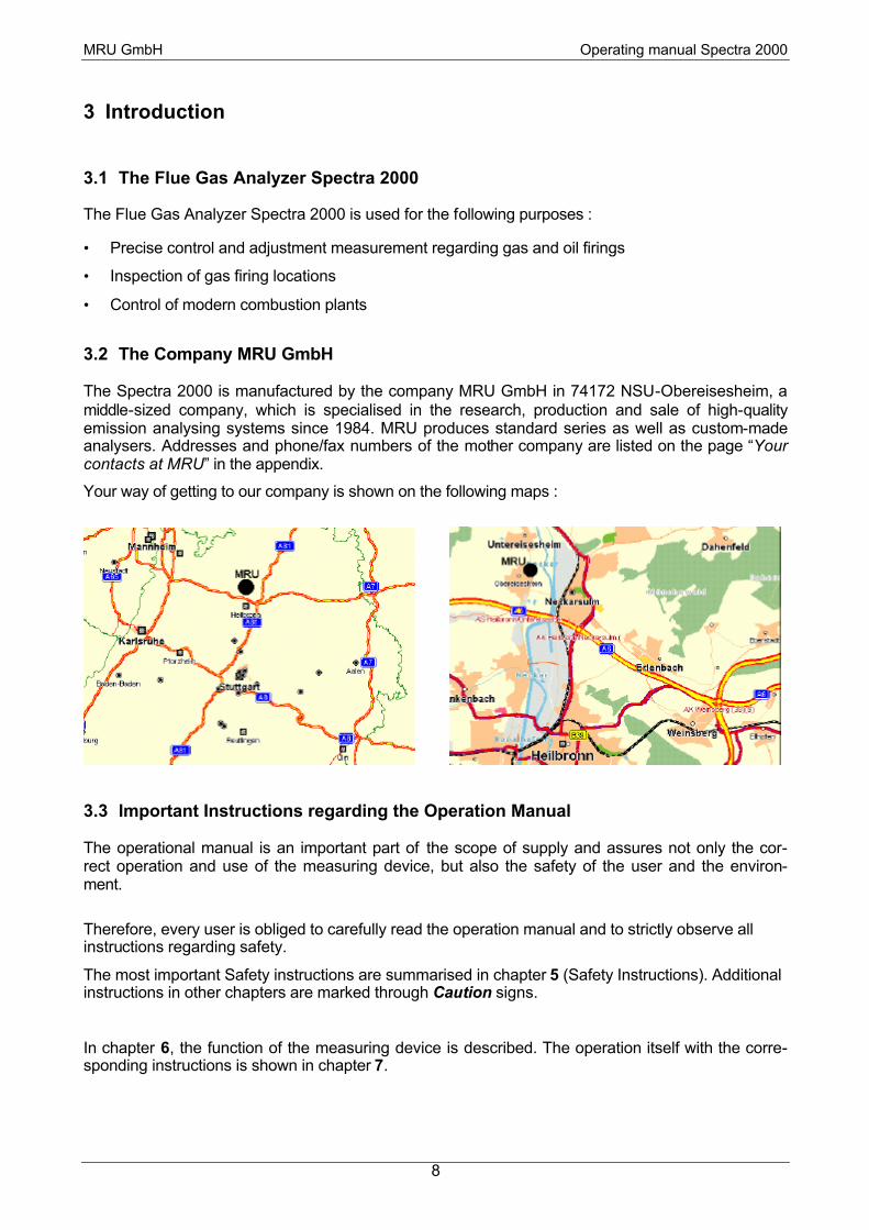
The Spectra 2000 is manufactured by the company MRU GmbH in 74172 NSU-Obereisesheim, a middle-sized company, which is specialised in the research, production and sale of high-quality emission analysing systems since 1984. MRU produces standard series as well as custom-made analysers. Addresses and phone/fax numbers of the mother company are listed on the page “Your contacts at MRU” in the appendix.
Your way of getting to our company is shown on the following maps :
3.3 Important Instructions regarding the Operation Manual
The operational manual is an important part of the scope of supply and assures not only the cor-rect operation and use of the measuring device, but also the safety of the user and the environ-ment.
Therefore, every user is obliged to carefully read the operation manual and to strictly observe all instructions regarding safety.
The most important Safety instructions are summarised in chapter 5 (Safety Instructions). Additional instructions in other chapters are marked through Caution signs.
In chapter 6, the function of the measuring device is described. The operation itself with the corre-sponding instructions is shown in chapter 7.

MRU GmbH Operating manual Spectra 2000
9
4 Safety Regulations
The following Safety instructions have to be strictly observed.
They are an essential and indispensable part of the user documentation.
Not observing can mean loss of warranty claims.
4.1 Safety Instructions
• The device Spectra 2000 is only to be used for its indicated purpose : the measurement of smoke and flue gases, of combustion air and gas temperature as well as for differential pressure measurement.
• The devices leaving the works of MRU GmbH are tested according to the regulations VDE 0411 (EN 61010) as well as DIN VDE 0701.
• The general basic principles for safety-relevant design of technical products according to DIN 31000/ VDE 1000 and the respective UVV = VBG 4 of the professional guilds for fine mechanics and electrical engineering are observed.
• The MRU GmbH assures that the device corresponds to the essential requirements of the legal regulations of the member states of the electro-magnetic compatibility ( 89/336/EWG) and to the low-voltage regulations ( 73/23/EWG).
4.2 Specific Safety Instructions
• The device is only to be used with the indicated power supply (230 V, 50 Hz). Should the bat-tery catch fire due to an operating error or a technical defect, the fire should only be extin-guished with the corresponding fire extinguishing equipment.
• The metal tube of the probe as well as any other metal parts / accessories are not to be used as electric conductors.
• The device is not to be used in and under water.
• The device is not to be placed near or directly at open fire or heat.
• The indicated range of temperature of the probe is not to be exceeded, as the probe, tempera-ture sensory mechanism and sensor could be destroyed.
• Plunges of the electronic measuring device have to be avoided.
• Caution: Moisture, being pumped out of the condensats trap can be slightly acidic.
• In case of skin contact IMMEDIATELY: clean respective parts of the body! Avoid contact of eyes with liquid! Please clean carefully all parts that were in contact with the condensats.
• After measurement, vent the device with fresh air and see to it that the probe is getting cold. As long as it is hot, the tube of the probe could burn persons or cause fire damages on inflammable underground.
• The exhalations of alcoholic combinations (f. ex. attenuation, petrol, spirit, varnish…) may be damage the sensors of the analyzer. Therefore it’s forbidden to preserve or use these fluids near by the device.
Quality Control Department MRU GmbH

MRU GmbH Operating manual Spectra 2000
10
5 Functional Description

MRU GmbH Operating manual Spectra 2000
11
5.1 Main Menus of Spectra 2000
The structure of this operational manual is based upon the structure of the main menus (see chap-ter 6.2bis 6.5).
The display of the device shows always one of the four main menus::
By means of the keys F1, F2, F3 and F4.the requested main menu can directly be selected.
MRU GmbH Operating manual Spectra 2000
12
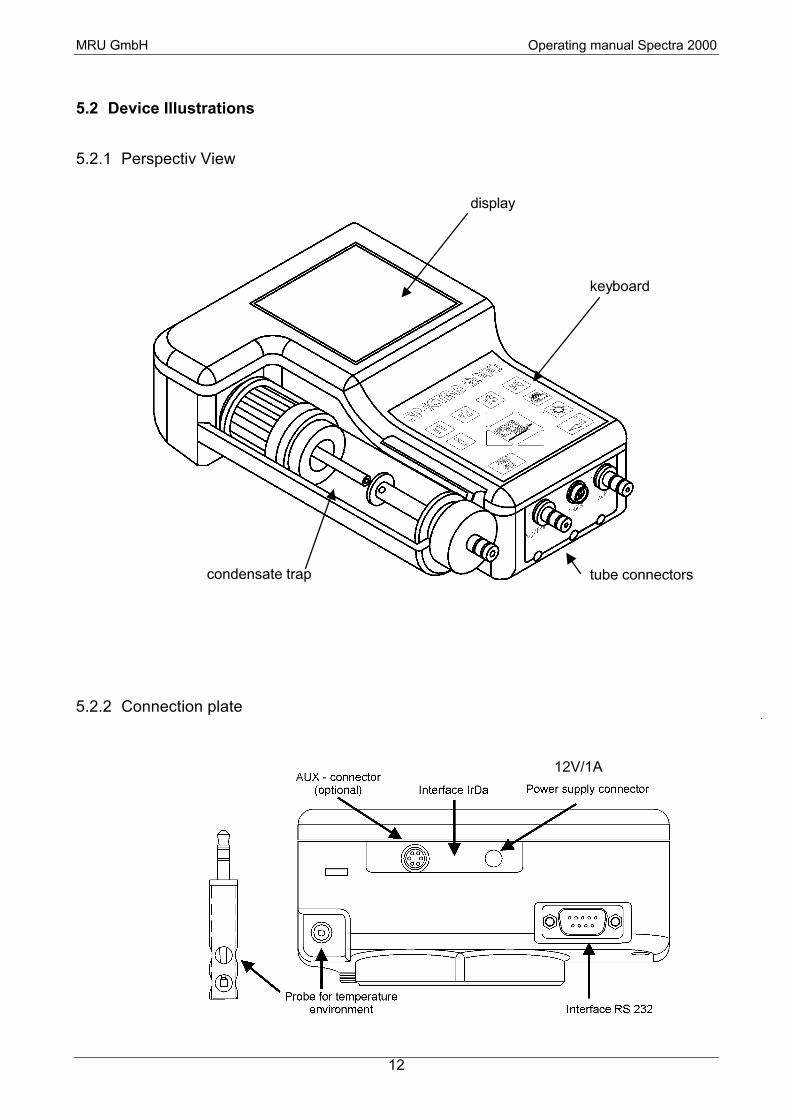
5.2 Device Illustrations
5.2.1 Perspectiv View
5.2.2 Connection plate
condensate trap
display
keyboard
tube connectors
12V/1A

MRU GmbH Operating manual Spectra 2000
13
5.2.3 Probe
5.2.4 Insert of the condensate trap
To remove, pull only the knurled part of the plug (2) in arrow head (3), to detach the latching device (1)
The ball with O-ring has to lead oblique in-side to the funnel (2) of the Spectra 2000.
Next to press down the condensate trap as far as the stopper (4) is clicking in the casing (3).

MRU GmbH Operating manual Spectra 2000
14
5.2.5 Keyboard
5.3 Operation of device
5.3.1 The keyboard
: switch measuring device on respectively off (see chapter 6.8)
The main menus (see chapter 5.1) can be reached as follows:
: the measurement menu (see chapter 6.2)
: the customer menu (see chapter 6.3)
: the data menu (see chapter 6.4)
: the extra menu (see chapter 6.5)
to start the function selected by the cursor
functional keys F1, F2, F3 and F4
info key (help) printer key
illumination
key
enter key power key
(on / off)
scroll keys
left, right, up, down

MRU GmbH Operating manual Spectra 2000
15
In other menus, the meaning of the functional keys differs and can be read in small texts in the function row in the bottom of the display.
The functional keys allow quick changes of device functions. The meaning of the functional keys are shown in the function row in the bottom of the display..
: mostly: change value, sometimes move cursor
: mostly: move cursor, sometimes change value
: to leave the current window, back to the last window
: start print (what will be printed depends on the context)
: switch on / off display illumination
: show operational instructions regarding the menu item
5.3.2 Power supply
The Spectra 2000 can be driven by:
1. MRU -internal battery (standard scope of supply)
2. MRU – line power (standard scope of supply) 12V / 1A
Measurements with line power:
When driven by line power, the device battery will be charged.
(see chapter:6.8)
It’s possible to take measurements while charging the battery.
Measurements with battery operation (battery control):
In the main menu the battery symbol shows the approximate remaining capacity of the battery.
0% 100%
In the other menus appears following flashing symbol if the battery is discharged up to
10% capacity:
When the battery is discharged, the following flashing message appears:
“Battery Empty”. If within one minute, the device will not be connected to the main supply circuit the device switches off.
MRU GmbH Operating manual Spectra 2000
16
6 Operation
6.1 Preparation for Measurement
Line Power Operation Spectra 2000
Only for use WITH the delivered line power Art.-No. 55490! The MRU – line power of the main supply circuit is to be connected to the Spectra 2000. Battery operation:
Battery capacity:
App. 8 hours (max.) with temperature of + 20°C (without illumination).
With lower temperatures, capacity reduces.
Operating temperature: (+5 °C bis +45°C)
CondensateTrap
• Mount condensate trap with filter like drawing chapter 5.2.4)
• Please check, if the condensate trap is empty and the filter is still white.
white ready for operation dark = replacement necessary
Connections and Tightness
• Check all plugged and screwed connections regarding their tight and correct fit.
• Check tightness of all tubes, tube connections and condensate trap (from probe tip to gas con-nection on device).
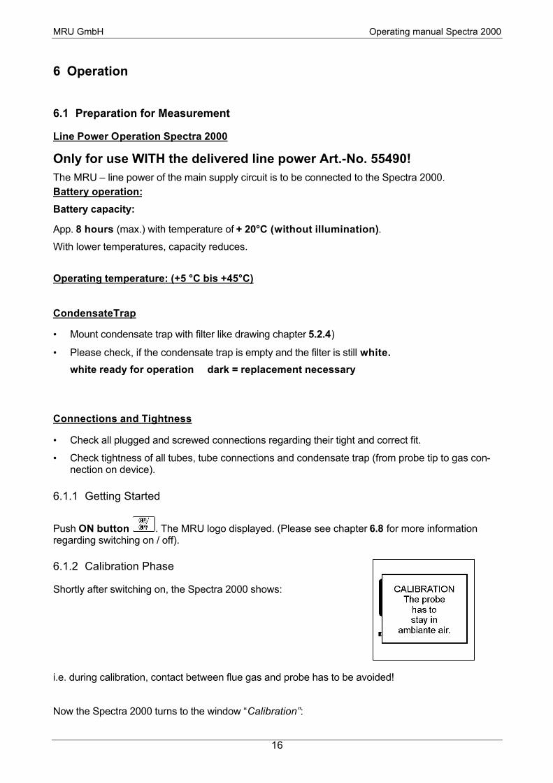
6.1.1 Getting Started
Push ON button . The MRU logo displayed. (Please see chapter 6.8 for more information regarding switching on / off).
6.1.2 Calibration Phase
Shortly after switching on, the Spectra 2000 shows:
i.e. during calibration, contact between flue gas and probe has to be avoided!
Now the Spectra 2000 turns to the window “Calibration”:

MRU GmbH Operating manual Spectra 2000
17
window “Calibration” “Measuring menu”
In the left upper corner a row is displayed, which shows the status of calibration..
In the right upper corner the battery symbol is shown, which indicates the approximate remaining battery capacity.
Calibration is effected in the background less for 2 minutes, max. 4 minutes. During this period of time, the flue gas measurement cannot be started. All other menu items can be selected.
You can use the calibration time in a reasonable way, e.g.
• by preparing your measuring instruments
• by choosing the correct fuel type (see chapter 6.2.4)
• by selecting the desired measurement program (see chapter 6.2.4)
• by making a (differential) pressure measurement (see chapter 6.2.1.1)
when calibration is finished,
the measuring device shows:
Now the Spectra 2000 is ready to effect flue gas measurements.
When the calibration is
terminated, the window
Measurement menu
appears.

MRU GmbH Operating manual Spectra 2000
18
6.2 Measurements
6.2.1 Pressure measurement (option)
In the menu „Pressure measurement“ four kinds of pressure (e.g. differential pressure, gas flow pressure etc.) and their corresponding denominations (max. 15 digits) can be entered manually.
All four values will be saved with the other measuring values and / or printed. The pressure meas-urements can be effected before flue gas measurements as well as afterwards when saving the measuring values.
Please connect tubes to - (blue) and + (yellow).
6.2.1.1 Pressure measurement before flue gas measurement
Change to “Measuring menu” (see chapter 5.1 )
window
“Measuring menu”
Move cursor with scroll keys in order to select menu item
“Pressure measurements” and press ENTER
window
“Pressure measurements“
Select via cursor the pressure, which should be measured next.
Start: start / Stop pressure measurement (“Stop“ will then be shown here)
Text: Input window will be opened (see chapter “) and denomination of the selected pressure can be modified (will be saved in device configurations)
all = 0:: Reset of all four pressures to 0.00 mbar in a fast and easy way
End: back to the “measuring menu” (pressure values will be saved).
If calibration is not yet finished, first the zero point is determined:
Disconnect the tubes at
- (blue) and + (yellow).
Then press
ENTER key:

MRU GmbH Operating manual Spectra 2000
19
6.2.1.2 Pressure measurement when saving the measured values
When saving measuring data, pressure measurements can equally be effected. With key F2
the window „Pressure meas-urements“ can be selected (as described in chapter 6.2.2.2)
Window: “Save measuring data /
pressure measurements”
Pressure measurements can now be effected as described in chapter 6.2.1.1.However, the two functions “edit” and “all=0” are not available here.
Select via cursor the pressure to be measured next
Start: start / stop pressure measurement (“stop” will then be shown here)
Customer: to the customer data (Four-window-row see chapter 6.2.2.4)
Save: end saving.
End: back to the “Measuring menu” without saving
6.2.1.3 Pressure values in data storage
In the window „Data view“ (see chapter 6.4.1)a change be-tween four windows is possible with key F2 same as in window “Save measuring data”: “Cus-tomer data”, “S&BT data”, “Measuring data” and “Pressure Measurement”
window “Data view / Pressure Meas.“
6.2.1.4 Print pressure values
Printing the measured pressures has not to be activated or deactivated by print selection.
When starting the print in the windows “Measurement”, “Last measured values” or “Data view”, all measured (i.e. not equal 0,00 mbar) pressure values are printed together with the measured val-ues.
However, the continuous differential pressure is activated respectively deactivated by print selec-tion.

MRU GmbH Operating manual Spectra 2000
20
6.2.2 Flue gas measurement
Change to the “Measurement menu“ (see chapter 5.1 )
Move cursor with scroll keys in order to select menu item „Soot measurement” and press Enter.
window
“Measuring menu”
Now the Spectra 2000 asks you to effect a central current search
window
“central current search“
End: end (respectively skip) central current search and go on with measurement
Positioning of the probe in the flow:
Slowly pass the cross section of the gas duct with the probe. The maximum gas temperature is found, when the probe tip is at the horizontal line and no more signal is audible. As soon as the maximum gas temperature is left, the arrow tip leaves the horizontal line and a signal is audible within certain time intervals. The further the maximal gas temperature is left, the shorter is interval of the signal. As soon as the flow is found, please fix the probe with the cone in this position.
The window “Measurement” can be adjusted individually, for 6 sec. the fuel/measuring which is selected appears at the dis-play(see chapter 6.5.2) e.g.:
window
“Measurement“
Change the visible page
switch to huge indication (see chapter 6.2.3)
Stop / start: Stop respectively start measurement (Start will be shown here)
COcut: modify CO cut-off limit temporarily (see chapter 6.2.2.1 and 6.5.2)
Save: to the “Save menu” (see chapter 6.2.2.2)
End: end measurement, back to the “Measuring menu”
Print momentary measuring values
set momentary values into the temporary buffer (see chapter 6.2.2.6)

MRU GmbH Operating manual Spectra 2000
21
6.2.2.1 Temporary change of CO cut-off limit
Press F2 = CO cut-off in the window: “Measurement”, the following window appears:
window:
“CO Cutoff”
Adjustment of the value in 100ppm steps from 0 ppm to 4000 ppm. The adjusted value determines the CO cut-off limit. If the value reaches this limit, the second pump is acti-vated in order to vent with fresh air and the CO sensor will be cut off from the gas line by a valve. If the limit value falls short by 20% during venting, measuring gas is newly ad-mitted to the CO sensor.
set 0: Set cut-off limit to 0, CO sensor is cut off from the gas line by a valve, then back to the measurement.
stand: Adjust standard limit value, which is allocated to the momentary measurement
program (see chapter 6.5.2)
End: back to measurement

MRU GmbH Operating manual Spectra 2000
22
6.2.2.2 Save measurement
If a measurement is to be saved, it has to be allocated to a customer. Thus you have four possibili-ties:
• To read in a customers number with the bar-code-scanner (option)
• select an existent customer by paging or searching (see chapter 6.2.2.5)
• new entry of a customer (see chapter 6.2.2.5)
• the device generates a customer (only with empty customer list), the customer number then is:
<0000001>.
By pressing F3 = Save in the window “Measurement”, the following window appears:
window
“Save / Customer data“
Paging backward / forward in the customers list (only in the window “Save / Customer data”
choice: to Customer search and customer new entry (see chapter 6.2.2.5)
S&BT: to the window (see chapter 6.2.2.3), Four-window-row (see chapter 6.2.2.4)
store: all measuring values will be saved and allocated to the selected customer. A mes-sage “measuring values saved” follows, then the window “Data view” opens (see chapter 6.4.1)
end: back to the “Measuring menu” without saving
: Print measuring values,
First you will reach the window “Soot and boiler temperature input” (see chapter 6.2.2.3), then press printer key once more.

MRU GmbH Operating manual Spectra 2000
23
6.2.2.3 Input of boiler temperature, soot values and oil derivative
In fact, the Spectra 2000 has no soot measurement, but you can nevertheless insert, save and print soot data.
There a different way of getting to this window:
• press key F2 = S&BT in the window “Save / customer data” (see chapter 6.2.2.2
• press printer key in the window “Measurements”(see chapter 6.2.2)
window ”Soot and Boiler temperature (S&BT)”
Move cursor
Change value of the selected field
Meas.: to the measuring values (Four-window-row see chapter 6.2.2.4)
Save: save momentary measuring values (see chapter 6.2.2)
End: back to the measuring menu (values are not saved)
: Print momentary measuring values

MRU GmbH Operating manual Spectra 2000
24
6.2.2.4 Four-window-row when saving
If saving has been started with key F3=store in the window measurement, you can change be-tween the following 4 windows with the F2 key before ending saving process:
Note:
The window
“Pressure measurement data” will not be shown, if your device does not have the pressure measuring option.
The row then limited to a three –window-row.
In all four windows, saving can be terminated with F3 and / or printing can be started with the printer key. The particular possibilities in these four windows are:
• Customer data: Paging, search, new entry in list of customers for co-ordination to a customer.
• Soot and boiler temperature input: Input of the soot numbers, of the oil derivate and the boiler temperature (see chapter 6.2.2.3)
• Flue gas measuring data:: Paging of the measuring indication
• Pressure measuring data: View and effect pressure measurements (see chapter 6.2.1.2)
MRU GmbH Operating manual Spectra 2000
25
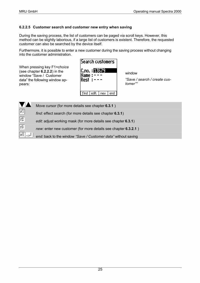
6.2.2.5 Customer search and customer new entry when saving
During the saving process, the list of customers can be paged via scroll keys. However, this method can be slightly laborious, if a large list of customers is existent. Therefore, the requested customer can also be searched by the device itself.
Furthermore, it is possible to enter a new customer during the saving process without changing into the customer administration.
When pressing key F1=choice (see chapter 6.2.2.2) in the window “Save / Customer data” the following window ap-pears:
window
“Save / search / create cus-tomer”“
Move cursor (for more details see chapter 6.3.1 )
find: effect search (for more details see chapter 6.3.1)
edit: adjust working mask (for more details see chapter 6.3.1)
new: enter new customer (for more details see chapter 6.3.2.1 )
end: back to the window “Save / Customer data” without saving

MRU GmbH Operating manual Spectra 2000
26
6.2.2.6 Temporary buffer
The Spectra 2000 gives the possibility to set the momentary values into a temporary buffer during effecting and continuing the measurement. Later on, the values can be brought back from the tem-porary buffer to the measuring window in order to print them out or / and to save them
To set the measuring values into the temporary buffer:
In order to set the measuring values into the temporary buffer, please press during meas-urement this key:
The device gives a short audible signal and continues with the measurement. In right lower corner of the display a twinkling “M” is shown for “Memory”:
measuring window with twinkling “M“ (values in temporary buffer)By pressing once more the key F4 during measurement, the values in the temporary buffer will be always overwrites with the current values.
To bring values back from the temporary buffer:
In order to bring the values back from the temporary buffer to the measuring window, please press first the key F1=stop
to stop the measurement.
Now you can change the current values and the values of the temporary buffer with the key F4 to compare both measurements.
Now it is possible to print and save as usual one of both measurements.

MRU GmbH Operating manual Spectra 2000
27
6.2.2.7 Chimney draft respectively fine draft measurement
The Chimney draft measurement is created as continuous measurement. I.e. the draft is meas-ured, indicated and printed in the same time as the flue gas values.
The gas sampling probe is equipped with a double tube. Connect the centred tube to the draft con-nection (green).
Important notes:
1.)
The Chimney draft measurement is subject to a minimal temperature drift. After 2-3 hours of con-tinuous measurement ( i.e. measurement without new zero point adjustment or calibration) the indicated chimney draft value can slightly, but increasingly drift away.
2.)
Determined by physical, every draft sensor has a zero point dependent on his position. This means, You should perform the calibration or the zero point adjustment in the same position, you intend to take the measurements.
Zero point adjustment:
During calibration, the Spectra 2000 automatically determines the zero point of the draft sensor. After 1 –3 hours, a new zero point determination may be necessary.
Procedure:
• Disconnect the fine draft tube from the draft connection (green) of the device.
• Press key on / off. The Spectra 2000 now changes to the power-off-window. Press now key F1=draft the device determines the zero point and changes back into operation mode.
• Reconnect the fine-draft-tube to the fine-draft-tube-connector (green).
6.2.3 Huge indication of the measured values
By pressing arrow-keys up /down in the window “Measure” (see chapter 6.2.2) to switch to a huge indication of a measure value.
window
“Huge indication”
back to normal view
change the measure value
direct selection of a measure value

MRU GmbH Operating manual Spectra 2000
28
6.2.4 Fuel selection / Measurement program selection
Change to the “Measuring menu” (see chapter 5.1):
window
“Measuring menu”
move cursor to the row Fuel selection or Measurement program selection
change the momentary fuel or the momentary Measurement program selection
starting measurement The fuels offered for selection correspond to those, which have been activated in the fuel preselec-tion (see chapter 6.5.1)
A list of fuel types in Germany and other countries can be found in the Appendix (Chapter 16.4
MRU GmbH Operating manual Spectra 2000
29
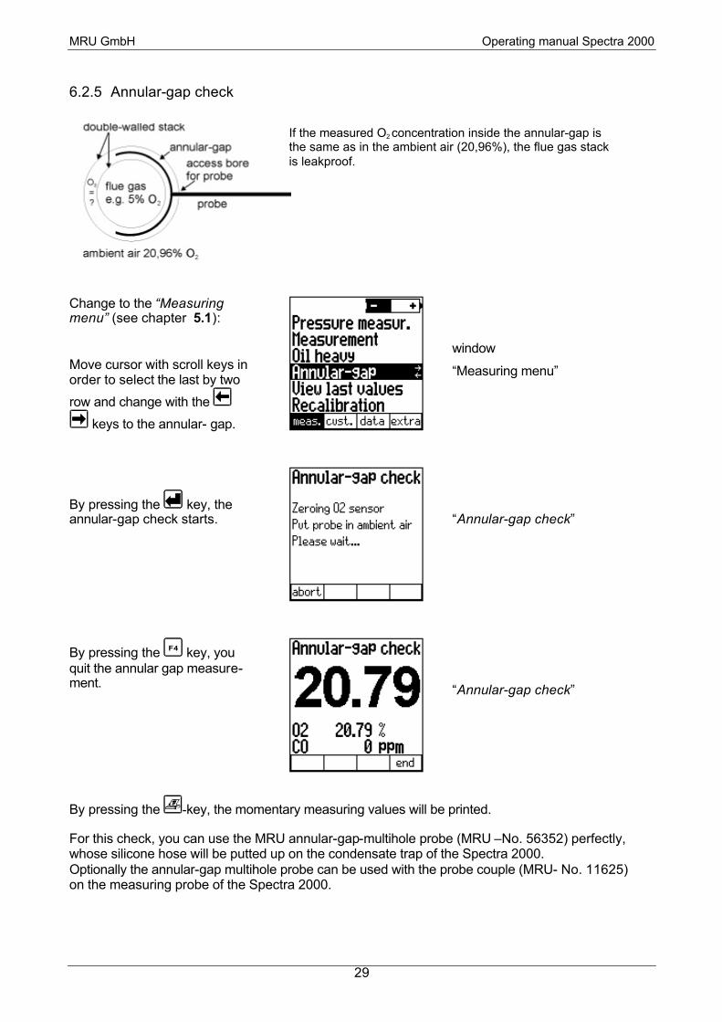
6.2.5 Annular-gap check
Change to the “Measuring menu” (see chapter 5.1):
Move cursor with scroll keys in order to select the last by two
row and change with the
keys to the annular- gap.
window
“Measuring menu”
By pressing the key, the annular-gap check starts.
“Annular-gap check”
By pressing the F4 key, you quit the annular gap measure-ment.
“Annular-gap check”
By pressing the -key, the momentary measuring values will be printed. For this check, you can use the MRU annular-gap-multihole probe (MRU –No. 56352) perfectly, whose silicone hose will be putted up on the condensate trap of the Spectra 2000. Optionally the annular-gap multihole probe can be used with the probe couple (MRU- No. 11625) on the measuring probe of the Spectra 2000.
If the measured O2 concentration inside the annular-gap is the same as in the ambient air (20,96%), the flue gas stack is leakproof.

MRU GmbH Operating manual Spectra 2000
30
6.2.6 View last values
Change to the “Measuring menu” (see chapter 5.1):
Move cursor with scroll keys in order to select menu item “view last values” and press ENTER
Window
“Measuring menu”
The window “Measurement” is now reached without starting the measurement. I.e. last measured values can be reviewed, saved and / or printed.
Above key F1, Start is now shown instead of Stop. When pressing the key, the measurement is started the same way as if it would have been started via the menu item “Measurement”.
6.2.7 Recalibration
Change to the “Measuring menu” (see chapter 5.1):
Move cursor with scroll keys in order to select menu item “Re-calibration” and press ENTER
Window
“Measuring menu”
The window “Recalibration” is now reached
Now the device asks you, if a restart and a calibration should be performed.
Window
“Recalibration”

MRU GmbH Operating manual Spectra 2000
31
6.3 Customer administration
The storage organisation inside the Spectra 2000 is created in a way, that in order to mark a saved measurement, a so-called customer must be existent, to whom the measurement can be allocated. The Spectra 2000 disposed of a customer’s storage of 300 (optional 3000) customers.
A customers data block consists of::
Field name Field size Input
Customers No. 15 necessary
Name 15 not necessary
2nd name 15 not necessary
Street and number 15 not necessary
ZIP code / city 15 not necessary
Phone #r 15 not necessary
An unlimited number of measuring data blocks (only limited by size of the storage) can be saved under one customer. When saving the measuring data, the corresponding customer has to be se-lected
Hint:
If generally, the customer administration is not used, but data nevertheless be saved, a customer should be created (see chapter 6.3.2.1), inserting one blank in the corresponding customer num-ber. In the future, the device saves all measuring data blocks without visible customer number and co-ordinates them to the pseudo customer.
MRU GmbH Operating manual Spectra 2000
32
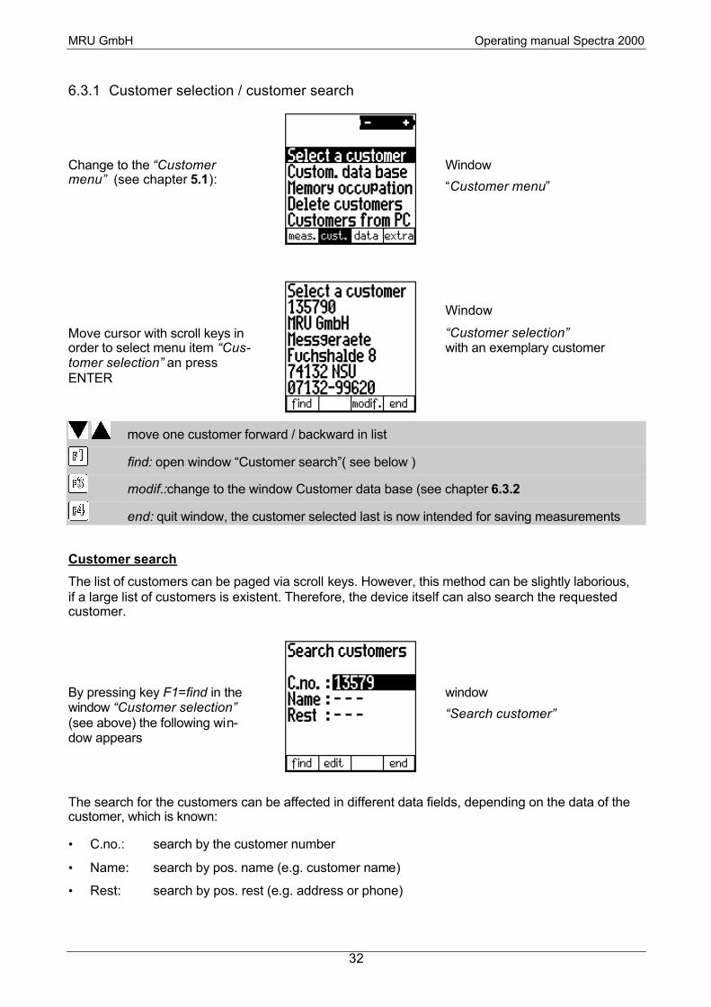
6.3.1 Customer selection / customer search
Change to the “Customer menu” (see chapter 5.1):
Window
“Customer menu”
Move cursor with scroll keys in order to select menu item “Cus-tomer selection” an press ENTER
Window
“Customer selection” with an exemplary customer
move one customer forward / backward in list
find: open window “Customer search”( see below )
modif.:change to the window Customer data base (see chapter 6.3.2
end: quit window, the customer selected last is now intended for saving measurements
Customer search
The list of customers can be paged via scroll keys. However, this method can be slightly laborious, if a large list of customers is existent. Therefore, the device itself can also search the requested customer.
By pressing key F1=find in the window “Customer selection” (see above) the following win-dow appears
window
“Search customer”
The search for the customers can be affected in different data fields, depending on the data of the customer, which is known:
• C.no.: search by the customer number
• Name: search by pos. name (e.g. customer name)
• Rest: search by pos. rest (e.g. address or phone)

MRU GmbH Operating manual Spectra 2000
33
Move cursor, the selected field determines, in which data fields the customer should be searched
find: effect search in the selected data field with the inserted search mask (more details see below). The previous window will be opened. If the search is successful, the found customer will be shown there, if not the note “search not successful” appears.
edit: open text input (see chapter 6.6) in order to modify the selected search mask.
end: quit window without effecting a search.
Explications and examples of a search
The device looks for customers in the complete customer list, which contains the inserted search mask in the selected data field. Majuscule and minuscule writing will be ignored during the search-ing process.
Here some search examples, which would find the exemplary customer on the left side:
C.no.: 135
C.no.: 9
Name: mru
Name: GmbH
Rest: 32-
Rest: HALDE
Here some search examples, which would not find the exemplary customer on the left side:
C.no.: 567
C.no.: 9962
Name: mrugmbh
Rest: 74172-99
(number does not contain “567”)
(“9962” is contained, but not in customer number)
(there is a blank between “mru” and “gmbh”
(contained, but not in one line)
Hint:
If after an effected search, you would like to keep on searching (i.e. in the same data field with the same search mask), please press key F1 twice.
MRU GmbH Operating manual Spectra 2000
34
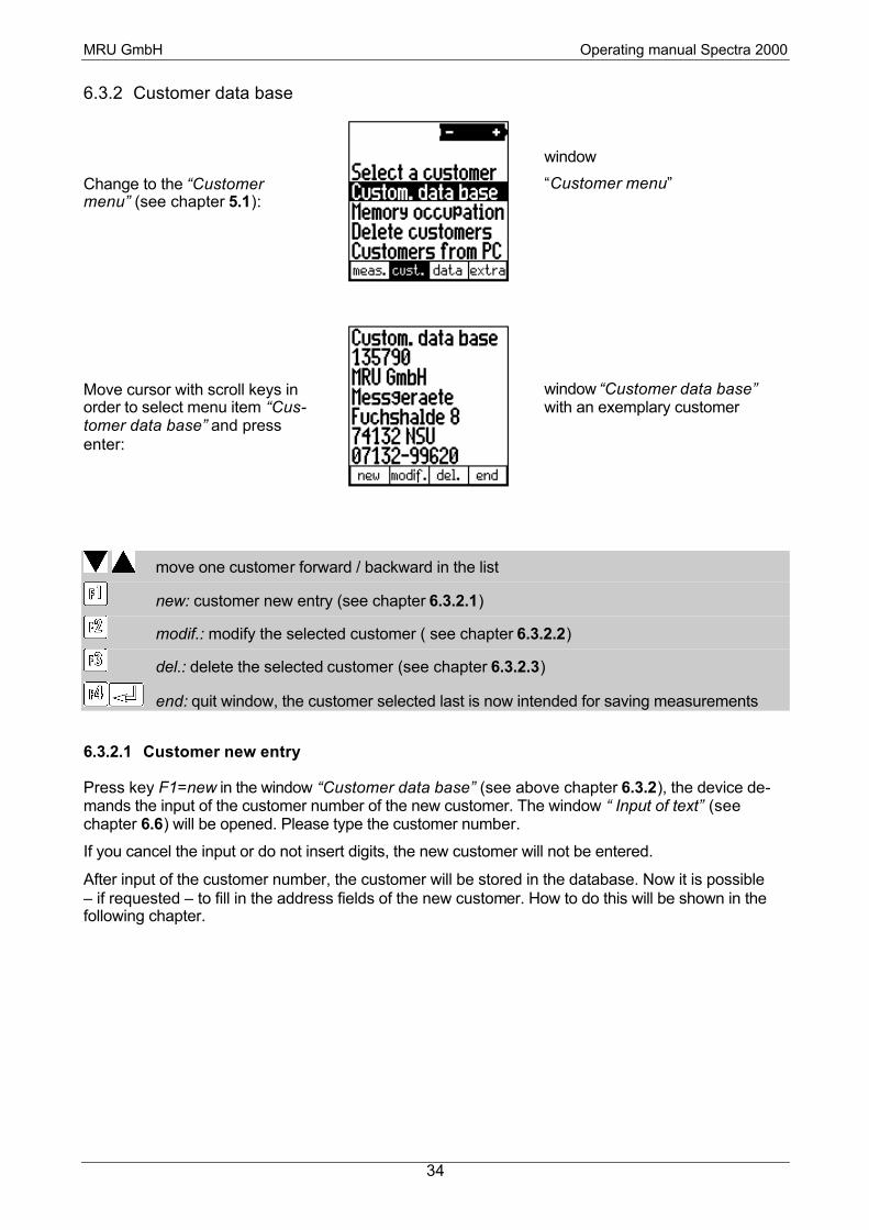
6.3.2 Customer data base
Change to the “Customer menu” (see chapter 5.1):
window
“Customer menu”
Move cursor with scroll keys in order to select menu item “Cus-tomer data base” and press enter:
window “Customer data base” with an exemplary customer
move one customer forward / backward in the list
new: customer new entry (see chapter 6.3.2.1)
modif.: modify the selected customer ( see chapter 6.3.2.2)
del.: delete the selected customer (see chapter 6.3.2.3)
end: quit window, the customer selected last is now intended for saving measurements
6.3.2.1 Customer new entry
Press key F1=new in the window “Customer data base” (see above chapter 6.3.2), the device de-mands the input of the customer number of the new customer. The window “ Input of text” (see chapter 6.6) will be opened. Please type the customer number.
If you cancel the input or do not insert digits, the new customer will not be entered.
After input of the customer number, the customer will be stored in the database. Now it is possible – if requested – to fill in the address fields of the new customer. How to do this will be shown in the following chapter.

MRU GmbH Operating manual Spectra 2000
35
6.3.2.2 Customer modifications
By pressing key F3=delete in the window “Customer data base” (see above chapter 6.3.2)
The following window appears:
window
"Customer modification" with an exemplary customer
move cursor in order to select another data field
edit: open input of text (see chapter 6.6) in order to modify the selected data field
end: quit window, the modification will be saved, the modified customer is now intended for saving measurements.
6.3.2.3 Customer deletion
By pressing key F3=delete in the window “Customer data base” (see above chapter 6.3.2)
the following window appears:
window
"Customer deletion" with an exemplary customer number
yes: the selected customer and all allocated measurements will be deleted from the storage. Afterwards back to the window “Customer data base”.
esc.: back to the window “Customer data base” without deletion.

MRU GmbH Operating manual Spectra 2000
36
6.3.3 Customers memory occupation
In the window “storage information”, the number of all, the occupied and free customer storage blocks will be indicated.
Change to the ”Customer-menu”(see chapter 5.1):
Window:
“Customer menu”
Move cursor with scroll keys in order to select menu item “Memory occupation” and press enter:
window
“Customer memory occupation”
end: back to the Customer menu
6.3.4 Deletion of all saved customers
Change to the “Customer me-nu“ (see chapter 5.1):
window
“Customer menu”
Move cursor with scroll keys in order to select menu item “De-lete customers” and press en-ter:
window
“Delete all customers”
yes: all saved customers and all measuring data will be deleted.
no: back to the “customer menu” without deletion

MRU GmbH Operating manual Spectra 2000
37
6.3.5 Transmission of customers from the PC
Via the RS 232 or infrared interface (IrDa) the Spectra 2000 is able to receive customer numbers including addresses from a (handheld) PC. For this, the necessary PC software (e.g. MRU Online View) has to be installed.
The necessary connection between the MRU measuring device and the PC or handheld PC has to be effected before transmission and is not to be disconnected during transmission:
• RS232: connect data transmission cable to the RS 232 interface of the PC and the Spectra 2000. (only when devices are switched off)
• IrDa: adjust infrared windows of both devices towards each other
Change to the ”Customer menu” (see chapter 5.1):
window:
“Customer menu”
window:
“Customers from PC”
abort
start:: the device asks, if you want to delete all stored measurements and customers
move cursor in order to select another field
Now the device asks you, if all saved customers and all meas-uring data will be deleted
window
“All customer and all measurements will be deleted”

MRU GmbH Operating manual Spectra 2000
38
yes: all saved customers and all measuring data will be deleted. The received cus-tomers from the new customer list.
no: no deletion, the received customers will be added to the customers list
If the customers number is already assigned the existing customer will be make topical with the new name / address and the potential measuring data remains allocated.
Now you will have to decide, which interface should be used for transmission:
window
“Interface selection“
RS 232 (cable): data will be received via RS 232 interface (cable)
IrDa 9600 Baud: data will be received via infrared interface (cordless)
data will be expected with 9600 baud (MRU-Pedias for Windows CE)
IrDa 1200 Baud: data will be received via infrared interface (cordless)
data will be expected with 1200 baud (other programs)
Now the Spectra 2000 waits for customer data at the selected interface and speed and shows this with the following window:
window
“Wait for customer data”
Now the data transmission at the PC can be started.
After transmission, the Spectra 2000 informs you, if the transmission was successful.
Transmission can be interrupted at any time with key F4=esc.

MRU GmbH Operating manual Spectra 2000
39
6.4 Data Administration
The Spectra 2000 disposes of a measuring data storage of 300 (optional 3000) measurements. A measurement has to be allocated to a customer when saving. Several measurements can be allo-cated to one single customer. In the measuring data storage measurements of one customer are listed directly one after the other, as measurements are arranged with respect to the customer.
When the measuring data storage is full, no more measurements can be saved without previously deleting the storage or parts of it.
A measuring data block (i.e. a saved measurement) consists of:
• Date and time of the measurement
• Customer number and address
• Values of the flue gas measurement (incl. AUX)
• Values of the soot measurement
• Values of the differential pressure measurement(s)
6.4.1 View stored data
Change to the “Data menu” (see chapter 5.1):
window
“Data menu”
Move cursor with scroll keys in order to sellect menu item “Customers from PC” and press ENTER
window
“View stored data,
,subview customer“”
in subview “Customer”: page one measurement forward / backward in subview “Measuring data”: change measurement page (see chapter 6.5.2)
find: search a measurement regarding customer number (see chapter 6.4.1.1)
S&BT: go to subview “Soot & Boiler temp” (see 4-window-row in chapter 6.4.1.2)
del..: delete the selected measurement (see chapter 6.4.1.3)
end: quit window, back to the “Date menu”
: print selected measurement

MRU GmbH Operating manual Spectra 2000
40
6.4.1.1 Data search
In the window “View stored data” (see chapter 6.4.1) all saved measurements can be paged via scroll keys. However, this method can be slightly laborious, if a large number of measurements is existent. Therefore, the requested measurement can also be searched by the device itself.
By pressing key F1=find in the window “View stored data” (see chapter 6.4.1), the following window opens:
window
“Data search”
find: effect search in the selected data field with the inserted search mask. The previous window will be opened. If the search is successful, the found customer will be shown, if no, the note "search not successful” appears.
edit: open text input (see chapter 6.6) in order to modify the selected search mask
end: quit window effecting a search It is not necessary that the search mask contains the complete customer number. Measurements will be searched in which the inputted search string is contained in the allocated customer number. Majuscule and minuscule writing will be ignored.
Hint:
If after an effected search, you would like to keep on searching (i.e. in the same data field with the same search mask) please press key F1 twice.
6.4.1.2 Four views of a measuring data block
The four views in the window “View stored data” (see chapter 6.4.1) shows the following:
Note:
The window “Pressure measuring data” will not be shown, if your device does not have the Pres-sure measuring option.
The row is then limited to a 3-window-row.

MRU GmbH Operating manual Spectra 2000
41
6.4.1.3 Deletion of a measuring data block
By pressing key F3=delete in the window “View stored data” (see chapter 6.4.1) the follow-ing window opens:
window
“Delete measuring data block”
yes: the selected measuring data block will be deleted. The customer data and other measurements of the same customer will be maintained. Then, the window “View stored data” opens again.
no: back to the window “View stored data” without deletion.
6.4.2 Measurement memory occupation
In the window “Measurement memory occupation” the number of all, the occupied and free meas-urement data storage blocks will be indicated.
Change to the “Data menu”
(see chapter 5.1):
window
“Data menu”
Move cursor with scroll keys in order to select menu item “Memory occupation” an press ENTER:
window
“Measurement data mempory
cccupation”
end: back to the “Data menu”

MRU GmbH Operating manual Spectra 2000
42
6.4.3 Deletion of all saved measuring data blocks
Change to the “Data menu”
(see chapter 5.1):
window
“Data menu”
Move cursor with scroll keys in order to select menu item “De-lete all data” and press ENTER:
window
“Delete all data”
yes: all saved measurements will be deleted. The customer data will be maintained.
Then the “Data menu” opens again.
no: back to the “Data menu“ without deletion.
6.4.4 Transmission of measuring data to PC
Change to the “Data menu”
(see chapter 5.1):
window
“Data menu”
Move cursor with scroll keys in order to select menu item “Send data to PC” and press ENTER:
Window
“Send data to PC”
move cursor in order to select the requested data transmission mode.
start: data transmission will be started
esc.: back to the “Data menu” without data transmission
MRU GmbH Operating manual Spectra 2000
43
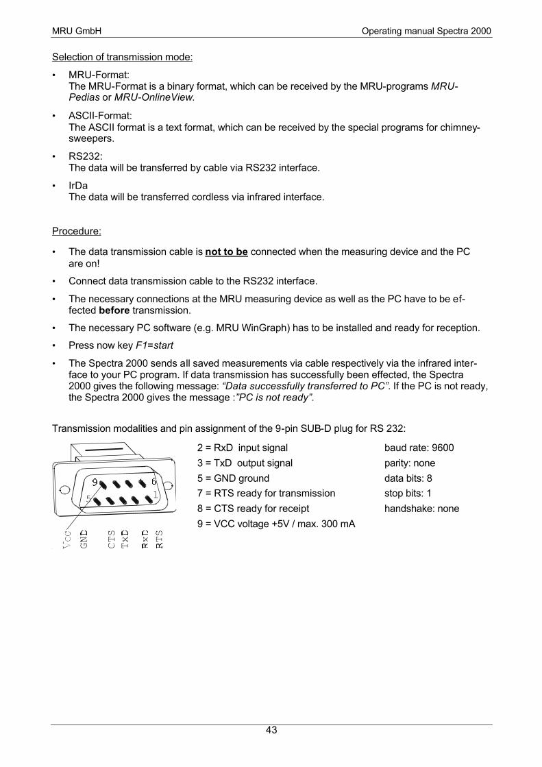
Selection of transmission mode:
• MRU-Format: The MRU-Format is a binary format, which can be received by the MRU-programs MRU-Pedias or MRU-OnlineView.
• ASCII-Format: The ASCII format is a text format, which can be received by the special programs for chimney-sweepers.
• RS232: The data will be transferred by cable via RS232 interface.
• IrDa The data will be transferred cordless via infrared interface.
Procedure:
• The data transmission cable is not to be connected when the measuring device and the PC are on!
• Connect data transmission cable to the RS232 interface.
• The necessary connections at the MRU measuring device as well as the PC have to be ef-fected before transmission.
• The necessary PC software (e.g. MRU WinGraph) has to be installed and ready for reception.
• Press now key F1=start
• The Spectra 2000 sends all saved measurements via cable respectively via the infrared inter-face to your PC program. If data transmission has successfully been effected, the Spectra 2000 gives the following message: “Data successfully transferred to PC”. If the PC is not ready, the Spectra 2000 gives the message :”PC is not ready”.
Transmission modalities and pin assignment of the 9-pin SUB-D plug for RS 232:
2 = RxD input signal
3 = TxD output signal
5 = GND ground
7 = RTS ready for transmission
8 = CTS ready for receipt
9 = VCC voltage +5V / max. 300 mA
baud rate: 9600
parity: none
data bits: 8
stop bits: 1
handshake: none

MRU GmbH Operating manual Spectra 2000
44
6.5 EXTRA / Device configurations
With delivery, the Spectra 2000 disposes of a standard pre-adjusted software, which should cover your needs in the most cases. However, the configuration is highly flexible and individually adjust-able.
If you would like to modify different configurations, we recommend to do this in a reasonable way. The better the configuration modification is planned, the lesser corrective action must be taken and the easier you are able to work with the device.
Take advantage of the possibility to individually adjust measurement programs, measuring indica-tion, printing outputs and self-selection fuel in a way, that all of your needs in practice are covered. Then less corrections regarding the configurations have to be effected.
After modifying the configurations, the device should be turned off for a short time, so that the modifications are saved and usable when turning on again.
6.5.1 Fuel type chart / User definable fuel types / Fuel type pre-selection
Change to the “EXTRA menu”
(see chapter 5.1):
window
“Extra-menu”
Move cursor with scroll keys in order to select menu item
„Fuel type chart“ and press
ENTER
window
“Fuel type chart”
select fuel type, also scroll up / down the fuel chart (more fuels are available than visible on one window)
same as F1: add or remove selected fuel to the pre-selected fuel types (selected = '∗')
+/-: add or remove selected fuel to the pre-selected fuel types (selected = '∗')
undiv.: to the window “User definable fuel types (see below
to change the O2ref. of the selected fuel with the keys .
end: back to the “EXTRA menu” Here, the customer can effect a fuel type pre-selection. The needed fuel types are selected and the superfluous ones are left out. In the “Measuring menu”, section “Fuel type”, only the pre-selected fuel types will appear.

MRU GmbH Operating manual Spectra 2000
45
User definable fuel types
Here, four fuels are adjusted individually. The name as well as all parameters (CO2max., O2 refer-ence values and the calculation parameters A1 and B) are adjustable. As the other fuel types, they can be pre-selected or left out.
move cursor in order to select a fuel type
same as F3: add or remove selected fuel to the pre-selected fuel types (selected = '∗')
modif.: modifiy fuel type parameters (see right illustration)
info: parameters of the fuel will be shown
+/-.: add or remove selected fuel to the pre-selected fuel types (selected = '∗')
end: back to the window “Fuel type chart”
In the right illustration “User definable fuel type” as usual with the scroll keys, the cursor can be moved and the values can be modified, with F1, the text input can be started and with F4 the win-dow will be closed..
6.5.2 Configure measurement programs (name, CO-limit, printout, indication)
Change to the “EXTRA menu” (see chapter 5.1 )
window
“Extra-Menü”
Move cursor with scroll keys in order to select menu item
“Program configuration” and press ENTER
window
“Program configuration”
window
“User definable
fuel types”
window
“Modify user definable fuel type”

MRU GmbH Operating manual Spectra 2000
46
select measurement program
change CO cut-off limit of the selected measurement program
edit: change name of the measurement program (Input of text see chapter 6.6)
print: print adjustment of the selected measurement program (see below)
indic.: adjustment of the measuring indication of the selected measurement program (see below)
end: back to the “EXTRA menu” Adjustment of the measuring indication
For every measurement program it is possible to adjust, which values should be visible in the measuring window during measurement. Each measurement program disposes of 6 pages à 7 lines which can be adjusted individually. During measurement, pages can be paged forward and backward
By pressing key F3=indic. in the window “Program configuration”, the measuring indication can be adjusted.
The following illustrations are examples for an adjustment of the measuring indication. In the lower left corner of the window, the current measurement program and page number (1…6) are shown:
Examples for "Adjustment of measuring indication"
move selection rows (in the first and last row, the page will be turned)
change measuring value to be indicated at the selected position
end: back to the window “Program configuration”
1st hint:
There is no problem in indication one measuring value on several pages. If e.g. T-Gas should al-ways be visible, it can be indicated e.g. on every page in the first line.
2nd hint:
If a page only consists of blank lines, it will not be visible when paging during measurement. If e.g. not more than 2 pages are needed, this way it can be avoided to page through 6 pages.
MRU GmbH Operating manual Spectra 2000
47
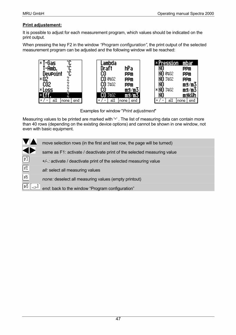
Print adjustement:
It is possible to adjust for each measurement program, which values should be indicated on the print output.
When pressing the key F2 in the window “Program configuration”, the print output of the selected measurement program can be adjusted and the following window will be reached:
Examples for window "Print adjustment"
Measuring values to be printed are marked with '∗' . The list of measuring data can contain more than 40 rows (depending on the existing device options) and cannot be shown in one window, not even with basic equipment.
move selection rows (in the first and last row, the page will be turned)
same as F1: activate / deactivate print of the selected measuring value
+/-.: activate / deactivate print of the selected measuring value
all: select all measuring values
none: deselect all measuring values (empty printout)
end: back to the window “Program configuration”

MRU GmbH Operating manual Spectra 2000
48
6.5.3 Set Date and time
Change to the “EXTRA menu” (see chapter 5.1):
window
“EXTRA-menu”
Move cursor with scroll keys in order to select menu item
“Set date and time” and press ENTER
window
“Set date and time”
change digit selected by cursor
move cursor
end: back to the “EXTRA menu” It is never possible (not even temporarily during adjustment process) to insert an impossible time or date.
Example: Month is 03 and should be modified to 11. It is not possible to increase 0 to 1 while the 3 is still there, as a month 13 does not exist. First, 3 has to be decreased to 1, then 0 increased to 1.

MRU GmbH Operating manual Spectra 2000
49
6.5.4 Settings
Change to the “EXTRA menu” (see chapter 5.1):
window
“EXTRA menu”
Move cursor with scroll keys in order to select menu item
“Settings” and press ENTER
window
“Settings”
select a device setting to be modified
modify selected device setting (see chart below)
aux.: to adjust the AUX input (see chapter 8.4),
lang.: to change the current country (language)(see chapter 6.5.5
end: back to the “EXTRA menu”
Position Possible adjustments Meaning
Speaker ON / OFF Audible sound when pressing a key
Contrast -50 % to 50 %.
(in paces of 5%)
Display contrast, 0% are normal with a tempera-ture of 20°C and depending on the individual sensation of the operator.
Helping hints. ON / OFF Explanation see below
Central current. ON / OFF Search of central current before measurement
Explanation of the setting “Helping hints”
There are a couple of messages which are generated automatically by the analyzer and which helps a beginner, but which may annoy an experience user:
• Calibration, the probe has to stay in ambient air • Calibration finished, sensors ready, device ready for measurement • Sensors free of gas, pump switched off for battery protection • Measurement values stored • Measurement started / stopped • Draft zero point follows, are both nozzles free of pressure?

MRU GmbH Operating manual Spectra 2000
50
6.5.5 Change the current language
window „Set the country (language)“
change the current country (language)
After the selection of a new language for the device there follows a warning, that some user set-tings will get lost.
change the current country (language) and restart
abort

MRU GmbH Operating manual Spectra 2000
51
6.5.6 Service values
If a device malfunction should occur (e. g. message during calibration: “O2 sensor not OK”), the malfunction can mostly be localised in the service window. The analogous values (= not calculated raw values) of all sensors will be displayed.
Please contact our after-sales service in case of a fault information (address / phone number see chapter 16.1). In order to localise the default, our technicians may ask you some service values
Change to the “EXTRA menu” (see chapter 5.1):
window
“EXTRA menu”
Move cursor with scroll keys in order to select menu item
“Service values” and press ENTER
window
“Service values”
scroll the service values single
scroll the service values one page up/down
temp.: see internal temperatures
info: see unit information (serial number, production date and software version)
end: back to the “EXTRA menu”
print service values, serial number, production date and software version
6.5.7 Adjustment
The adjustment menu is protected against use of non-authorised persons by a pin code.
If by accident, the PIN code log-in has been started, just press to return to the
“EXTRA menu”

MRU GmbH Operating manual Spectra 2000
52
6.5.8 Illumination
Illumination ON / OFF: By pressing key the background illumination of the display can be turned on and off.
Automatic OFF: As soon as the battery symbol starts flashing, the illumi-nation is switched off (for reasons of battery protection).
The display illumination can be re-activated by pressing key .
6.6 Input of text
A number of texts and denominations can be inputted in the Spectra 2000 (e.g. the name of the user definable fuel types, customer numbers, names of pressure). When starting the input, the following window always appears:
window "Input of text"
It is able to feed a chain of signs up to 15 sign max. The input follows in the way of overwriting.
move the sign cursor or the input cursor (if the sign cursor is not visible)
abort: cancel, input will not be taken
del.: the character selected by cursor will be deleted
ins.: a blank will be inserted
OK: end text, input will be saved
Enter: insert the character below the sign cursor
After the input of text, you will get back to the window, where you started the text input. If the input was not cancelled with F=esc, the new text will be shown at the corresponding place now.

MRU GmbH Operating manual Spectra 2000
53
6.7 Printing procedure with the Infrared-printer HP 82240B(option)
• Switch-on infrared (IR) printer (option). Optical connection between infrared (IR) printer and Spectra 2000 has to be provided and must not to be interrupted during printing procedure.
Protect infrared (IR) printer against direct ray of sunshine (detailed description about max. dis-tance and transmission angle please see manual of Hewlett Packard).
• Printing procedure is started in window “Measure”, “Last measuring values”, ”Store measure-ment”, “View data” or “Service”.
• Press printing key
Note: The number of prints can be determined by pressing the printer key (e.g. pressing key twice = 2 prints).
Print out values (e.g.):
Your company address can be saved upon request.
Customer: _ _ _ _ _ _ _ _ _ _ _ _
****************************** * M R U Spectra 2000 * * 000 000 * ****************************** 12:08:00 09:07 Nat. gas light 15,4 % Program 2 T-das 37.3 °C T-air 18.7 °C Dew point -.- °C O2 21.0 % CO2 7.0 % Losses 15.2 % Eff. 84.8 % Excess air -.- Fine draft 0.00 hPa CO 0 ppm CO un. 0 ppm CO 3%O2 0 ppm CO 0 mg/m3
CO 3%O2 0 mg/m3 CO 0 mgkWh CO 0 mg/MJ ABC 28.0 °C Oil 65°C
MRU GmbH Fuchshalde 8
74172 Obereisesheim Tel. 07132/9962-0 Fax. 07132/9962-20

MRU GmbH Operating manual Spectra 2000
54
4
5
1
2
3
6
End of printer paper roll: Do not use printer paper until paper end, in case that the paper end is pasted to the inner body (HP paper is not pasted).
Please see to it that printing is only started with enough paper inserted. Printing without paper
reduces lifetime of your printer !
1 – OFF / ON
2 – Print contrast
3 – Paper advance
4 - Door
5 – Paper slot
6 – IR-receiver
Insert printer paper roll:
Cut end of paper properly.
Do not use paper with wrinkles or bad paper edges.
Avoid any obstructions of the printer mechanism!
Open paper protection flap.
Position paper like illustrated (see printer manual of Hew-lett Packard).
Pull paper through lid of printer.
Press (3) until paper is coming out.
In case of paper jam, pull paper back very carefully!
Insert printer paper roll and close protection flap.
Never operate printer without paper!
Do not pull paper from the front press (3)
MRU GmbH Operating manual Spectra 2000
55
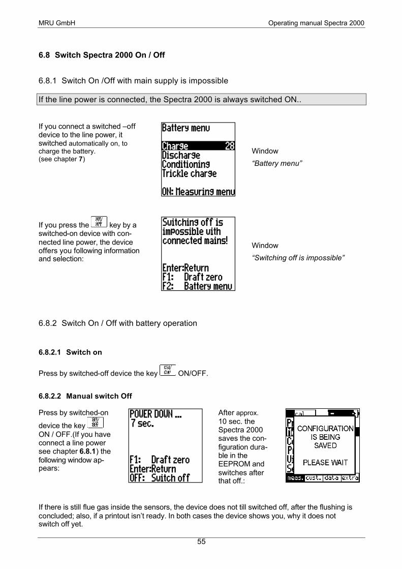
6.8 Switch Spectra 2000 On / Off
6.8.1 Switch On /Off with main supply is impossible
If the line power is connected, the Spectra 2000 is always switched ON..
If you connect a switched –off device to the line power, it switched automatically on, to charge the battery. (see chapter 7)
Window
“Battery menu”
If you press the key by a switched-on device with con-nected line power, the device offers you following information and selection:
Window
“Switching off is impossible”
6.8.2 Switch On / Off with battery operation
6.8.2.1 Switch on
Press by switched-off device the key ON/OFF.
6.8.2.2 Manual switch Off
Press by switched-on
device the key ON / OFF.(If you have connect a line power see chapter 6.8.1) the following window ap-pears:
After approx. 10 sec. the Spectra 2000 saves the con-figuration dura-ble in the EEPROM and switches after that off.:
If there is still flue gas inside the sensors, the device does not till switched off, after the flushing is concluded; also, if a printout isn’t ready. In both cases the device shows you, why it does not switch off yet.

MRU GmbH Operating manual Spectra 2000
56
6.8.2.3 Manual switch off in case of emergency
In cause of, it is not possible to switch off the device on the ‘normal way’ (e.g. the software is ‘hanging’ or ‘plunge down’, you can switch off the device by pressing simultaneously the keys F4 and light. Attention:
The configuration (user settings) does not getting stored and there is no checking about the flush-ing of the sensors.
6.8.2.4 Automatically switch off
If the following circumstances are coming true, the device powered down independent: • The line power is not connected
• The device is not in the measurement
• The device is not in the adjustment
• Since the last pressing of a key pasted approx. 5 min.
• The sensors are flushed (CO low and O2 high)
To prevent a deep discharging by mistake, the device switch off, independent of the circumstances above in case of the battery capacitance reached a critical low.
7 Battery maintenance (charge and conditioning)
The Spectra 2000 has intelligent processor controlled functions, to ensure the maximum of endur-ance (operation time between the charge) and the maximum service life of the selected NiCd-high- powered battery.
For a NiCd - battery you have to notice following points:
• Avoid overloading, the temperature of the battery becomes high and the battery can be dam-aged.
• The battery should be complete charge and complete discharge from time to time, to avoid the so-called “memory-effect”
For the fulfilment of both demands the Spectra 2000 independent ensured:
• By charge of the device, the voltage and the temperature of the battery become monitored and the process will be finished, as soon as the battery has reached the maximum capacitance, but before the battery is getting overloaded.
• The device offers you the function “Conditioning“ (see chapter 7.3). On the occasion the battery will be completely charged, after that completely discharged and after that completely charged again. Next the device passes over to the “Trickle charge” (see chapter 7.4)
This process fulfils the above-described condition. The device suggests you this function inde-pendent, if since the last conditioning at least pasts 30 days and you plug in the line power be-tween Friday 16 p.m. and Sunday 17 p.m.

MRU GmbH Operating manual Spectra 2000
57
If you connect a switched –off device to the line power, it switched automatically on, to charge the battery. (see chapter 7)
Window
“Battery menu”
Move the cursor ion order to select a menu item
To start the selected function
To start normally measurement (at the beginning calibration), the battery will be charged in the background to a certain degree.
After switching on, the device suggested independent a useful function, by putting the cursor ap-propriate. On the right edge of the cursor you see a counter running down from 30 to 0. If it reaches zero the momentary selected function will be carried out, unless you are pressing the key ENTER before.
7.1 Charge
If you plug the line power to the switched off device, the Spectra 2000 suggests independent the function charge. The cursor of the window „Battery menu“ selects then menu item “Charge”. Unless you choose another function, the charge starts after 30 seconds.
If in the window “Battery menu” the function “Charge cycle” is selected, then the battery will be full loaded
Window
“Charge cycle”
Stop charge cycle (of course then the battery is not full loaded) The charge cycle takes the maximum of 4 hours. According to the condition of the battery at the beginning the time will be reduced.
The device concludes the charge cycle independent and than follows the “Compensation charge” (see chapter 7.4)

MRU GmbH Operating manual Spectra 2000
58
7.2 Discharge
If you select in the window „Bat-tery cycle“ the function “Dis-charge“ the battery will be dis-charged ( and following inde-pendently charged):
Window
“Discharge cycle“”
to break off the discharging (after that follows none independent charge!) The discharging is a part of the “Conditioning” (see chapter 7.3) and will be executed of which course independently of the between the charges.
However there is one case, it is useful to trigger this process manually:
If you would like to conditionate the battery, but still you need the device during the next 12 hours (max. period of a conditioning) you should be select the function “Discharge”. Next the device in-dependently selected the function “Charge” (see chapter). At the latest of 8 hours the battery is completely charged and the previous discharge does her well.
The discharging takes maximum four hours. According to the condition of the battery at the begin-ning, the time will be reduced.
The device concludes the discharge cycle independently and than follows the “Charging“ (see chapter7.1) and after that to the “Trickle charge” (see chapter 7.4)
Note: The device will be warm up during the discharging, especially at the back of the device. This is standard on no reason of concern. During the discharging the electrical power will be transformed by means of the device heating in heat. The temperatures will be shown as information on the dis-play.
7.3 Conditioning
Like above in the introductory sentences of the chapter “Battery maintenance (charge and condi-tioning)“ explained, it is advisable to conditionate the battery from time to time. The device suggested you independently this process, if since the last conditioning at least 30 days are past and if you connect the Spectra 2000 with the line power between Friday 4.00 p.m and Sunday 5.00 p.m. .The row of the window “Battery menu” after that is located on the line “Conditioning”. If you don’t act, the conditioning will be started after 30 seconds. Of course, you can always start manual a conditioning. You should only consider, that this process is able to take up to 12 hours.
If in the window “Battery menu“ the function “Conditioning” is selected (automatically or manual) then the conditioning independent runs in the following phases:

MRU GmbH Operating manual Spectra 2000
59
1.) Charge 2.) Discharge 3.) Charge
The device independently concludes the conditioning – the “Trickle charge” follows (see chapter 7.4)
to abort the respective phase of conditioning (Perhaps the capacitance of the battery is then too low)
7.4 Compensation Charge (Trickle Charge)
The function “Trickle charge“ makes it unable that the capacitance of the battery takes off through self-discharge. The battery will be charged constantly. Tie function can be executed in a long-term basis.
After the functions “Charge” (see chapter 7.1) and “Conditioning” (see chapter 7.3) the Spectra 2000 executes this function independent.
If you select in the window “Bat-tery menu“ the item “Trickle charge” during one of the func-tions “Charge” or “Conditioning“ is concluded,- the “Trickle charge” started
Window
“Trickle charge”
abort “Trickle charge” (alternative you can pull off the connection the line power) If the Spectra 2000 independently pass over after the execution of “Charge” or ”Conditioning” to this function , then the battery is completely loaded.
MRU GmbH Operating manual Spectra 2000
60
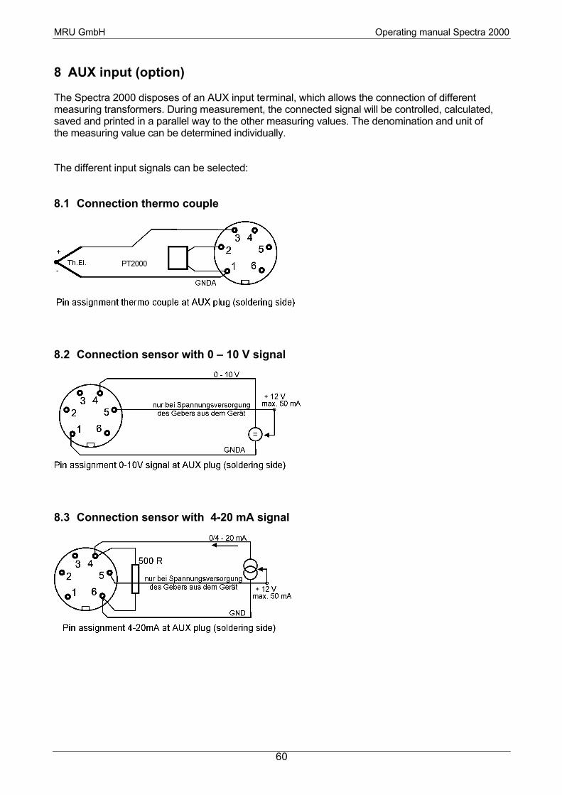
8 AUX input (option)
The Spectra 2000 disposes of an AUX input terminal, which allows the connection of different measuring transformers. During measurement, the connected signal will be controlled, calculated, saved and printed in a parallel way to the other measuring values. The denomination and unit of the measuring value can be determined individually.
The different input signals can be selected:
8.1 Connection thermo couple
8.2 Connection sensor with 0 – 10 V signal
8.3 Connection sensor wíth 4-20 mA signal
PT2000

MRU GmbH Operating manual Spectra 2000
61
8.4 Adjustment of the Aux input
Change to the “EXTRA menu” (see chapter 5.1):
Move cursor with scroll keys in order to select menu item “Device settings” and press ENTER:
By pressing key F1 = aux., the following window appears (e.g. for temperature measurement):
Selection of the different positions (kind, name, unit, min., max.)
Modify selected position (kind, min., max.)
edit: modification of the text input
end: quit window, save input, back to window “Device settings”

MRU GmbH Operating manual Spectra 2000
62
Explanation of the positions to be adjusted
Position Explanation
Kind Thermo:
A connected Thermo couple will be read (see illustration chapter 8.1) The positions unit, min. and max. are pre-set by the device. Now it is possible to measure a tem-perature from –40°C to +1000°C.
4...20mA:
A connected 4-20mA signal sensor will be read (see illustration chapter 8.3)
0...10V:
A connected 0-10V signal sensor will be read (see illustration chapter 8.2)
OFF:
No signal of the AUX input will be read..
Name Name of the measuring item:
With means of key F1 = edit, the name of the measuring item to appear in the meas-uring window and on the print can be inputted. (e.g. T- suppl.)
Unit Name of the measuring unit (only with 0…10V or 4…20mA)
With means of key F1 = edit, the name of the measuring unit to appear in the measur-ing window and on the print can be inputted (e.g. “°F”
Min. Lower measuring range limit (only with 0…10V or 4…20mA)
Please indicate here, which measured result corresponds to the lowest signal (0V or 4mA)
Max Upper measuring range limit (only with 0…10V or 4…20mA)
Please indicate here, which measured result corresponds to the highest signal (10V or 20mA)
Resolut. Fineness of measurement (only indication, will be calculated by the device)
Examples for the resolution calculated by the device
Difference “Max. – Min” “Resolution” Ex. “Min” Ex. “Max.”
<= 100 (1 - 100) 0.01 0 100
<= 1000 (101 - 1000) 0.1 500 1500
<= 10000 (1001 - 10000) 1.0 -5000 +5000
> 10000 (10001 - 100000) 10.0 -5000 +5001

MRU GmbH Operating manual Spectra 2000
63
9 Device heating
The Spectra 2000 disposed of an internal device heating, which heats the inside of the device.
The device heating needs an external power supply:
• Connection of the line power to 230 V
• Connection to the machine’s mains (12 V DC) of a vehicle (cigar jack) with a corresponding adapter cable (option).
Both ways of external voltage supply allow an adjustment of the internal temperature of the device in order to avoid overheating.
The device heating accomplishes two jobs:
• Quick adjustment of the device is lower than ( > 5 °C) in winter time, if the device was stored in cold ambience for a longer time (for more details, see chapter 9.1)
• Avoids formation of condensats inside the device (for more details, see chapter 9.2)
9.1 Adjustment of operational temperature
If the inside temperature of the device is lower than +5°C when switching it on, it should be heated before being able to make measurements:
Although the display is temperature compensated, it can be black with temperature below zero inside the device. Therefore, in this case, also fluorescent diodes and speakers are used for your information.
If the line power is connected, the following window appears:
The device beeps in short intervals; in order to communicate is opera-tional condition also in an audible way.
The device heating works. As soon as a temperature of +10°C is rea-ched, the device automatically reboots and starts with the calibration.
If no line power is connected, the following window appears:
The device beeps in short intervals; in order to communicate is opera-tional condition also in an audible way.
If the device is connected to the vehicle’s mains, the device heating works and the temperature will increase.

MRU GmbH Operating manual Spectra 2000
64
9.2 Prevention of condensate inside the device
Combustion’s of hydrocarbons provokes formation of water, which is contained in hot flue gas. As soon as the flue gas cools down, water condensats and becomes liquid.
The flue gas will be cooled down to the ambient temperature from the probe and especially in the condensate trap during the transport. Therefore, it concentrates in the condensate trap.
After passing the condensate trap, the flue gas still contains water. If the inside temperature of the device would keep on decreasing, also the gas parts of the measuring device (tubes, pumps, sen-sors) would collect water.
The device heating makes sure, that the inside temperature of the device is least as high as the flue gas temperature. This means, that the flue gas temperature cannot keep on decreasing.
The inside temperature of the Spectra 2000 is adjusted to app. 27°C.
We recommend, especially in wintertime, when the device may have been stored in a cold place, to connect the mains power cable to make the device heating work.
Attention:
Also when operated with line power – so with device heating – the condensate trap of the Spectra 2000 has to be emptied and checked in regular intervals!

MRU GmbH Operating manual Spectra 2000
65
10 Calculation basis
10.1 Analysis and calculation
Continuously measured items Unit Standard Option
O2 [%] X
Air temperature (thermo couple)) [°C] X
Flue gas temperature (thermo couple) [°C] X
CO [ppm] X
Fine draft [hPa] X
Differential pressure [mbar] X
NO [ppm] X
AUX user defined X
Via the microprocessor the following is measured (standard and optional):
Continuous transformation to CO and NO CO NO NOx
[ ppm ] (calculated from NO) X
[ ppm ] in reference to 0% rest O2 (not diluted) X X X
[ ppm ] in reference to O2 reference value dep. on fuel X X X
[ mg/m3 ] X X X
[ mg/m3 ] in reference to O2 reference value dep. on fuel X X X
[ mg/kWh ] X X X
[ mg / MJ ] X X X
More continuously calculated measuring items Unit
CO2 [%]
Efficiency [%]
Losses [%]
Excess air -
Dew Point [°C]

MRU GmbH Operating manual Spectra 2000
66
10.1.1 Formula of Siegert
The calculation of ETA and the exhaust losses is carried out according to the formula of Siegert.
CO2, Excess air, Losses, ETA
−⋅=
max2
21max22
O
OCOCO
2max2
max2
2
max2
OO
O
CO
CO
−==λ
( )
+⋅−= B
CO
ATTlosses ambgas
2
1 (Temp. in °C, A1 and B inclined of fuel type))
lossesETA −= %100
Not continuously measured items Unit Option 4 user definable difference pressures [mbar] X
Flow rate [m/s] X

MRU GmbH Operating manual Spectra 2000
67
11 Technical specifications
Standard equip. : - continuous measurement of O2, CO, flue gas temp., air temp., draft - calculation of CO2, excess air, losses etc. - CO cut-off via solenoid valve and purge via pump - gas sampling probe, Ø 8 mm, length 300 mm - removable probe tube with inner tube and connector - 2,7 m gas sampling and fine draft tube, with temperature adjustment (NiCrNi) - short combustion’s air sensitive element - condensate trap with filter (star filter) - robust leathercase with additional compartments
Indication: LCD graphical display (65 mm x 65 mm) illuminated, 7-row display,
Power supply: MRU line power 12V / 1A
Operational temp.: +5°C to +45°C Storage temp.: -20°C to +50°C
Temperature Measuring
Range of probe: 650°C, max. 1100°C with high temperature probe tube (option)
Measuring ranges: Oxygen (O2) 0 - 21,0% vol. Carbon monoxide (CO) 0 - 10000 ppm (H2 compensated)
long duration less 25 % Carbon dioxide (CO2) 0 - 20% (calculated) Nitrogen monoxide (NO) 0 - 2000 ppm (optional) combustion air temperature 0 - 150°C gas temperature 0 - 650°C fine draft -100,00 hPa to +100,00 hPa differential pressure -100 mbar to + 100 mbar efficiency / ETA 0% - 100% losses 0% - 100% excess air is calculated
Accuracy: oxygen (O2) ± 0,2 % absolute carbon monoxide (CO) ± 10 ppm or ± 5% of measuring value carbon dioxide (CO2) ± 0,3 % absolute nitrogen monoxide (NO) ± 10 ppm or ± 5% of measuring value temperature ± 1°C for T< 50°C; ± 2°C for T< 125°C; ± 3°C for T< 250°C; ± 4°C for T> 250°C; fine draft / differential pressure ± 0,3 mbar or ± 1% of measuring value
Resolution: oxygen (O2) 0,1 % carbon monoxide (CO) 1 ppm carbon dioxide (CO2) 0,1 % nitrogen monoxide (NO) 1 ppm temperature 0,1°C fine draft 0,5 Pa differential pressure 0,01 hPa
Sensors: oxygen (O2) electrochemical cell carbon monoxide (CO) electrochemical cell

MRU GmbH Operating manual Spectra 2000
68
nitrogen monoxide (NO) electrochemical cell temperature NiCrNi-thermo element + KTY fine draft / differential pressure expansive measuring bridge sensor
Special Equipment:
• Continuous measurement of NO.
• Measurement of differential pressure (4 x individually nameable)
• Measurement of the dynamic pressure with means of the Prandlt tube and measurement of the flow speed and the flue gas volume
• serial data transmission via RS232 interface or infrared (IrDa)
• Barcode Reader
• adapter cable to the cigarette lighter of a vehicle
• High temperature probe tube with screwed sintered metal filter
• PC software Online View
• AUX Plug for the connection of thermo couple or 0 – 10 V signal or 4 – 20 mA signal
• continuous measurement via AUX input of: 1. temperature (PT 2000 sensitive element) or 2. standard signal 0...10 V or 0...5 V or 3. standard signal 4-20mA
• Infrared data transmission (IrDa-format)
• Continuous transmission in MRU format during measurement (over RS 232 interface)
Data storage: Standard: 300 memory locations Option: 3000 memory locations
Printer: - thermo printer, infrared - thermo print paper, paper width: 58 mm, paper length: 15 m - number of prints: depending on the print adjustment (app. 125 prints)
Case: robust plastic case, coloured
Dimensions: width x length x height: 150 x 200 x 70 mm
Weight (without access.) app.. 1000 g
Protetive system: IP 21

MRU GmbH Operating manual Spectra 2000
69
12 Storage
12.1 Operational and storage temperature
Operational temperature: 5°C to 45°C
The device is equipped with a device heating
It is driven
• Via line power supply 230 V AC/50Hz • Via adapter cable (option) to the cigar jack of a vehicle
After switching it on, the device is not ready for measurement with temperatures below +5°C, but will be heated internally by the device heating.
This is indicated with a double audible tone every 2 seconds as well as with a display indication until a device temperature of app. +15°C is reached.
If no mains power supply is available, the device indicates this with an audible tone every second as well as with a display indication.
Storage temperature : -20°C to +50°C.
Long-term non-operation and storage:
1. charge battery every 4 weeks at the line power
2. store in a dry place.
If the above mentioned points should not be respected, the Spectra 2000 can be damaged by a total discharge of the battery and by oxidation inside the device.
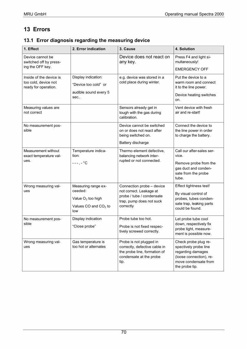
MRU GmbH Operating manual Spectra 2000
70
13 Errors
13.1 Error diagnosis regarding the measuring device
1. Effect 2. Error indication 3. Cause 4. Solution
Device cannot be switched off by press-ing the OFF key.
Device does not react on any key.
Press F4 and light si-multaneously!
EMERGENCY OFF
Inside of the device is too cold, device not ready for operation.
Display indication:
“Device too cold” or
audible sound every 5 sec..
e.g. device was stored in a cold place during winter.
Put the device to a warm room and connect it to the line power.
Device heating switches on.
Measuring values are not correct
Sensors already get in tough with the gas during calibration.
Vent device with fresh air and re-start!
No measurement pos-sible
Device cannot be switched on or does not react after being switched on.
Battery discharge
Connect the device to the line power in order to charge the battery.
Measurement without exact temperature val-ues.
Temperature indica-tion:
- - - , - °C
Thermo element defective, balancing network inter-rupted or not connected.
Call our after-sales ser-vice.
Remove probe from the gas duct and conden-sate from the probe tube.
Wrong measuring val-ues
Measuring range ex-ceeded:
Value O2 too high
Values CO and CO2 to low
Connection probe – device not correct. Leakage at probe / tube / condensate trap, pump does not suck correctly
Effect tightness test!
By visual control of probes, tubes conden-sate trap, leaking parts could be found.
No measurement pos-sible
Display indication
“Close probe”
Probe tube too hot.
Probe is not fixed respec-tively screwed correctly.
Let probe tube cool down, respectively fix probe tight, measure-ment is possible now.
Wrong measuring val-ues
Gas temperature is too hot or alternates
Probe is not plugged in correctly, defective cable in the probe line, formation of condensate at the probe tip.
Check probe plug re-spectively probe line regarding damages (loose connection), re-move condensate from the probe tip.

MRU GmbH Operating manual Spectra 2000
71
13.2 Error diagnosis regarding the condensats trap
1. Effet 2. Cause 3. Solution
Dirt and / or humidity inside the device
No filter effect
Sensor failure
Pump failure
Fine filters are wet and / or dirty. Check filters more often
Renew them if neces-sary (white = OK)
Brown-black = renewal
Wrong measuring values Cover, intermediary unit, plexiglas tube and locking pieces are not tightly fixed respectively screwed
Check tightness with every filter change..

MRU GmbH Operating manual Spectra 2000
72
14 Maintenance and After-Sales Service
14.1 Cleaning and Maintenance
• Occasionally: cleaning of the probe and the probe tube
• After each measurement: remove gas-sampling tube from the measuring device in order to dry it.
• Grease connector in order to keep the O-rings supple.
• Charge battery every 4 weeks at the line power in case of long-term non-operation
• Clean and dry or change dirty and wet filters
Illustration
Pos Denomination Ordering No..
1 Stopper 56436
2 Union stem 56375
3 Middle part 56437
4 High-grade steel tube 56545
5 Vessel 56438
6 Cover 56439
7 Ball 56440
8 O-Ring 27 x1 ,5 56476
9 O-Ring 6 x 1 (2X) 13271
10 O-Ring 16 x 3 13273
11 O-Ring 27 x 1,5 56476
12 Star Filter 11165

MRU GmbH Operating manual Spectra 2000
73
14.2 Self Diagnosis
The Spectra 2000 is equipped with a self-diagnosis program.
All internal functions are monitored and displayed if necessary
Switch on device: all values are checked
Error message: In the “Main menu” e.g. “O2 sensor not OK / device not ready for measure-ment” is displayed. Measuring device can be activated in all menus except for menu “Measurement” (measurement cannot be started).
Service program: In case of an error message, change to the “EXTRA menu” and select “Service”. The mV values of e.g. the sensors, the flue gas temperature sensitive element etc. are displayed. Afterwards, the mV values are indi-cated, which restrict the “OK” range:
1. Sensors: ( to fresh air )
O2-sensor: +200 mV to + 500 mV
CO-sensor: -10 mV to + 10 mV
H2 sensor: -20 mV to + 20 mV
3. sensor (option): -20 mV to + 20 mV (NO or Big-CO)
2. The AUX terminal can individually be assigned with sensitive elements, we only indicate here the upper and lower limit in the good range
value in mV Denomination ( 1 AUX possible)
-500mV to +500mV PT2000: (PT2000-sensor AUX-terminal)
-500mV to +500mV Th AUX ( Thermo element AUX-terminal)
-500mV to +500mV mA-AUX: ( signal input AUX-terminal)
-500mV to +500mV V AUX : (signal input AUX-terminal)
3. Temperatures:
TH Gas: (Thermo element gas) -500mV to +500mV with room temp.: app.. 0mV
KTY Gas: (reference temp. gas) -500mV to +500mV with room temp.: app.. 200mV
TH air: (Thermo element air) -500mV to +500mV with room temp.: app. 0mV
KTY air reference temp. air) -500mV to +500mV with room temp.: app.. 200mV
KTY-Sensor (Temp. of sensors): 0 to 5000mV with room temp.: app. 2000mV
(Appendix 1: chart in mV regarding temp. in °C)
4. Fine Draft
Draft: -500mV to 500mV not pressurized
-20 mV to + 20mV

MRU GmbH Operating manual Spectra 2000
74
5. Bias-Voltage
Bias: (indication of bias voltage) +2750mV to + 3250mV
If the above-mentioned values are exceeded the allocated ranges, a defect is present.
If no sensitive elements are connected, the corresponding fields in the service print are marked with
- - - - - (Negative service-value) or with + + + + + (positive service-value)
14.2.1 T-Sensor
AD [ mV ] 163 170 177 185 192 200 208 216 225 233 242
T [ °C ] 0 5 10 15 20 25 30 35 40 45 50
14.2.2 PT2000
AD [ mV ] 200 204 208 212 216 219 223 227 231 235 239
T [ °C ] 0 5 10 15 20 25 30 35 40 45 50
Scroll service data: and
Activate printer with: print the current service data, device number and EPROM ver-sion number
Note: The number of prints can be determined by pressing the printer key (e.g. pressing printer key twice = 2 prints
Quit service program: get back to “EXTRA menu” with key .
14.3 Service-Maintenance Plan
A check of Spectra 2000 at our Service Department is necessary:
• after 1000 working hours or
• if the last check of the Spectra 2000 was effected 11 month ago.
As soon as this period is exceeded, Spectra 2000 displays several times after switching on:

MRU GmbH Operating manual Spectra 2000
75
A complete check at our Service Department includes function control and calibration respectively cleaning of the following components:
a) Sensors O2 - CO. if integrated NO.
b) pumps
c) internal / external tubes
d) battery
e) printer (option)
f) fine draft
g) electronics: 1. CPU-printed circuit board
2. mains supply PCB
3. front panel display
4. time and date
5. temperature entries
h) gas sampling probe
i) filter box / condensate trap
Expenditure of repairs higher than DM 500,00 net:
- Cost estimate will be sent by fax or mail. Only upon receipt of your written agreement, repair will be done.
Expenditure of repairs lower than DM 500,00 net:
- No information will be sent, only if it has been required on your repair order.
! ! CAUTION ! !
DUE FOR
SERVICE !
Press Enter

MRU GmbH Operating manual Spectra 2000
76
Replacement of wearing parts:
- If a replacement of wearing parts, which are more expensive than DM 5,00 as well as if test gas is necessary, it will be invoiced.
- For repairs, please return your device only in packing protecting the environment.
14.4 Spare Parts, Accessories and Wearing Parts
prices upon demand.
Options:
56523 Expansion with NO-sensor
55425 Infrared thermo printer
56527 3000 Memory locations 56528 Probe with 1,5m, instead of 2,7m gas sampling tube
56529 Probe with 4,0m, instead of 2,7m gas sampling tube 56524 integrated differential pressure measurement +/- 0...100mbar
56109 bar-code scanner incl. software
56525 bi-directional IRDA-interface for the cordless transmission 56526 AUX-terminal for connection for some more input signals
56088 Measurement of the dynamic pressure with means of the Prandlt tube and measurement of the flow speed (option difference pressure necessary)
56521 Practical alu frame case for device and accessories 56522 ABS – case, black
55665 Genuine leather case
Accessories, Replacement 11505 Shoulder strap 55548 Probe tube 180mm, enlighten, incl. cone
51560 Multi-hole probe with 2,5m probe tube
55498 Multi-hole exchangeable probe tube for standard probe handle 11789B Combustion air temperature sensitive element, 65 mm, incl. Rubber cone and solenoid
fixing with cable 2,5 m
12018 Combustion air temperature sensitive element in 300 mm probe tube application
51531 Cable to PC, length 3 m 50648 Probeholder, slewing for Ø 8mm
51833 Hand soot pump 15150 Graphic-Software-Package MRU ONLINE VIEW, for Windows 95/98 and 2000(“basic”
15151 s.a., inc. storage. of the measuring values in any intervals (“profi”).
56533 adapter cable to the cigar jack of a vehicle
Wearing Parts 56548 Service cleaning set contains following parts:
1 Stk. 11165 Star filter
2 pieces 55915 Filtertab for fine filter, screwable, loose 18x15 mm)

MRU GmbH Operating manual Spectra 2000
77
1 piece 51513 Humidity filter PTFE
0,5m 51165 silicone hose 2x1 transparent 1 piece 51548 probe brush 6 mm, length 350mm with nylon border
1 piece 51547 Blow-out ball
1 piece 51596 Bottle of spirit 100ml 1 piece 11627 Cone for probe 8mm Ø
1 piece 51579 Dust cloth MRU 1 piece 51563 Silicone grease 6g tube
1 piece 50970 Control port sealing, 1 sheet = 16 sealing stickers, with MRU-Logo
1 piece 50108 Packing (PE-bag.) for replacement parts. 1 piece 53022 Zweckform Labels Nr. 3666 38x21,2 mm
1 piece 52795 Cone for probe out of silicone, 5mm drilling for combustion air tem-perature sensitive element
2 pieces 56476 O-Ring 27x1,5 mm 1 piece 51517 O-Ring 32x1,5 mm
1 piece 13273 O-Ring 16x3 mm
4 pieces 13271 O-Ring 6x1 mm tube bushing 4 pieces 52369 O-Ring 5x1 mm tube bushing
11165 Star filter, for washing out
56116 Spare printer rolls (1selling unit = 5 rolls à 25 m)
50970 Control port sealing (1 sheet = 16 sealing stickers) 11700 Soot paper (1 bag contains 200 pieces)
11701 Soot comparison scale 51867 Transparent envelope for measuring protocol (minimum delivery: 10 pieces)

MRU GmbH Operating manual Spectra 2000
78
14.5 Repair Slip

MRU GmbH Operating manual Spectra 2000
79
15 Packing and Removal
15.1 Packing degree
Packing degree dated July 12, 1991
Should the local waste disposal establishment not accept MRU packing material, there is of course the possibility to give it back to our works or operational staff.
However, please understand, that the transport costs resulting from the return cannot be our cost.
15.2 Return of Hazardous Waste
-Disposal-return-garantee-
MRU is engaged to take back all delivered parts of hazardous waste, which cannot be disposed “in a normal way”.
The return has to be effected free of charge for our company. Hazardous parts are e.g. sensors.
16 Appendix
16.1 Adresses ”Your contacts to MRU”
manufacturer
Address: M R U Messgeräte für Rauchgase und Umweltschutz GmbH Fuchshalde 8 D-74172 Neckarsulm-Obereisesheim
Phone.: +49 71 32 – 99 62 - 0 Fax: +49 71 32 – 99 62 - 20 Service-Hotline: +49 71 32 – 99 62 -59
E-Mail: [email protected] Web-Site: www.mru.de
Mail Address: P.O Box 2736
D-74017 Heilbronn
Expree Station: Heilbronn-Main station
self collect

MRU GmbH Operating manual Spectra 2000
80
16.2 Accessory
16.2.1 Multihole Probe
16.2.1.1 Multihole Probe Cap
Mounting of the multihole probe cap MRU No. 55498:
1. Unscrew the knurled nut at the probe tube; remove probe tube from probe handle.
2. Unscrew the protective cap of the multihole probe cap..
3. Fit the multihole probe cap in the probe handle and screw with the knurled nut.
Protective cap knurled nut
16.2.1.2 Multihole Probe with Tube
Connect the tube of the multihole probe according to illustration.
multihole probe with
tube line MRU No.51560

MRU GmbH Operating manual Spectra 2000
81
16.2.2 High temperature probe tube
High temperature probe tube with sintered metal filter MRU No. 56768
16.2.3 Adapter cable to cigar jack of a vehicle
MRU No.56533

MRU GmbH Operating manual Spectra 2000
82
16.3 Bar code scanner (option)
A bar code scanner in conjunction with the corresponding softwate-option (MRU – No.:56109) in Verbindung mit einer entsprechenden Gerätesoftware-Option (MRU-Nr. 56109), makes the search of customers or the customers new entry considerable easier
The bar code scanner will be connected at the RS 232 interface, automatically recognized by the device and is able to read bar codes from index cards or stickers.
Possibilities of application:
1. storage of measuring values to existing customers in the device
2. new entry of customers in the device and following storage of measuring values.
3. Customer search in the device memory.

MRU GmbH Operating manual Spectra 2000
83
16.4 Lists of Fuel Types
A1 = corrective factor based upon fuel
B = corrective factor
Fuel CO2max A1 B
Germany
Butan 14,1 % 0,45 0,007
Erdgas E (H) 12,1 % 0,37 0,009
Erdgas LL (L) 11,8 % 0,37 0,009
Flüssiggas P 13,7 % 0,42 0,008
Heizöl EL 15,4 % 0,50 0,007
Heizöl S 15,9 % 0,50 0,007
Holz 20,3 % 0,60 0,009
Kohle 19,1 % 0,59 0,009
Kokereigas 10,8 % 0,29 0,011
Propan 13,7 % 0,43 0,007
Stadtgas 11,7 % 0,35 0,011
Braunkohle 19,4 % 0,39 0,009
Austria
Heizöl EL 15,3 % 0,52 0,007
Heizöl L 15,8 % 0,53 0,007
Heizöl M+S 16,1 % 0,54 0,007
Erdgas H 11,9 % 0,39 0,009
Erdgas H Gebl. 11,9 % 0,41 0,009
Propangas g31 13,7 % 0,45 0,007
Prop.g31 Gebl. 13,7 % 0,47 0,007
Butan 14,1 % 0,45 0,007
Zechenkoks 20,6 % 0,74 0,001
Holz trocken 19,4 % 0,60 0,009
Belgium
Algerise 12,0 % 0,37 0,009
Antracite Koke 18,1 % 0,64 0,009
Butaan 14,1 % 0,45 0,007
Coke 18,8 % 0,64 0,009
Droog Hout 19,4 % 0,60 0.009
Extra Zw. Stook 15,9 % 0,50 0,007
Cokesgas 10,1 % 0,35 0,011
Lichte Stook 15,4 % 0,50 0,007
Fuel CO2max A1 B
Propaan 13,8 % 0,47 0,011
Vette Kolen 17,6 % 0,59 0,009
Noordzee Gas 12,1 % 0,37 0,009
Van Slochteren 11,9 % 0,37 0,009
Zware Stook 15,7 % 0,50 0,007
Czechia
Topny Olej 15,4 % 0,50 0,007
Zemni Plyn 11,8 % 0,37 0,009
G20 12,1 % 0,37 0,009
Svitiplyn 12,8 % 0,35 0,011
Propan-butan 13,8 % 0,42 0,008
Propan 13,7 % 0,43 0,007
Uhli 19,1 % 0,59 0,009
Suche Drevo 20,5 % 0,60 0,009
France
Gasoil 15,3 % 0,50 0,007
Fioul lourd 15,7 % 0,50 0,007
Extra lourd 15,9 % 0,50 0,007
Gaz Nat. Slocht. 11,9 % 0,37 0,009
Gaz Nat. MD.Nord 12,1 % 0,37 0,009
Gaz Nat. Algeri. 12,0 % 0,37 0,009
Propane 13,8 % 0,47 0,011
Butane 14,1 % 0,45 0,007
Gaz de Coke 10,1 % 0,35 0,011
Charbon Anthra. 18,1 % 0,64 0,009
Charbon gras 17,6 % 0,59 0,009
Coke 18,8 % 0,64 0,009
Bois sec. 19,4 % 0,60 0,009
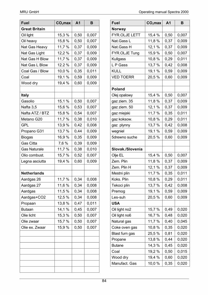
MRU GmbH Operating manual Spectra 2000
84
Fuel CO2max A1 B
Great Britain
Oil light 15,3 % 0,50 0,007
Oil heavy 15,8 % 0,50 0,007
Nat Gas Heavy 11,7 % 0,37 0,009
Nat Gas Light 12,2 % 0,37 0,009
Nat Gas H Blow 11,7 % 0,37 0,009
Nat Gas L Blow 12.2 % 0,37 0,009
Coal Gas / Blow 10,0 % 0,35 0,011
Coal 19,1 % 0,59 0,009
Wood dry 19,4 % 0,60 0,009
Italy
Gasolio 15,1 % 0,50 0,007
Nafta 3,5 15,6 % 0,53 0,007
Nafta ATZ / BTZ 15,8 % 0,54 0,007
Metano G20 11,7 % 0,38 0,010
GPL 13,9 % 0,42 0,008
Propano G31 13,7 % 0,44 0,009
Biogas 16,9 % 0,35 0,009
Gas Citta 7,6 % 0,39 0,009
Gas Naturale 11,7 % 0,38 0,010
Olio combust. 15,7 % 0,52 0,007
Legna asciutta 19,4 % 0,60 0,009
Netherlands
Aardgas 26 11,7 % 0,34 0,008
Aardgas 27 11,6 % 0,34 0,008
Aardgas 11,5 % 0,34 0,008
Aardgas+CO2 12,5 % 0,34 0,008
Propaan 13,8 % 0,47 0,011
Butaan 14,1 % 0,45 0,007
Olie licht 15,3 % 0,50 0,007
Olie zwaar 15,7 % 0,50 0,007
Olie ex. Zwaar 15,9 % 0,50 0,007
Fuel CO2max A1 B
Norway
FYR.OLJE LETT 15,4 % 0,50 0,007
Nat.Gass L 11,8 % 0,37 0,009
Nat.Gass H 12,1 % 0,37 0,009
FYR.OLJE Tung 15,9 % 0,50 0,007
Kullgass 10,8 % 0,29 0,011
L P Gass 13,7 % 0,42 0,008
KULL 19,1 % 0,59 0,009
VED TOERR 20,5 % 0,60 0,009
Poland
Olej opalowy 15,4 % 0,50 0,007
gaz ziem. 35 11,8 % 0,37 0,009
gaz ziem. 50 12,1 % 0,37 0,009
gaz miejski 11,7 % 0,35 0,011
gaz koksow. 10,8 % 0,29 0,011
gaz plynny 13,7 % 0,42 0,008
wegniel 19,1 % 0,59 0,009
5drewno suche 20,5 % 0,60 0,009
Slovak./Slovenia
Olje EL 15,4 % 0,50 0,007
Zem. Plin 11,8 % 0,37 0,009
Zem. Plin H 12,1 % 0,37 0,009
Mestni plin 11,7 % 0,35 0,011
Koks. Plin 10,8 % 0,29 0,011
Tekoci plin 13,7 % 0,42 0,008
Premog 19,1 % 0,59 0,009
Les-suh 20,5 % 0,60 0,009
USA
Oil light no2 15,7 % 0,49 0,020
Oil light no6 16,7 % 0,48 0,020
Natural gas 11,7 % 0,40 0,045
Coke oven gas 10,8 % 0,35 0,020
Blast furn gas 25,5 % 0,81 0,020
Propane 13,8 % 0,44 0,020
Butane 14,3 % 0,45 0,020
Coal 19,2 % 0,50 0,015
Wood dry 19,4 % 0,60 0,020
Manufact. Gas 10,0 % 0,35 0,020