Embed Size (px)
Citation preview
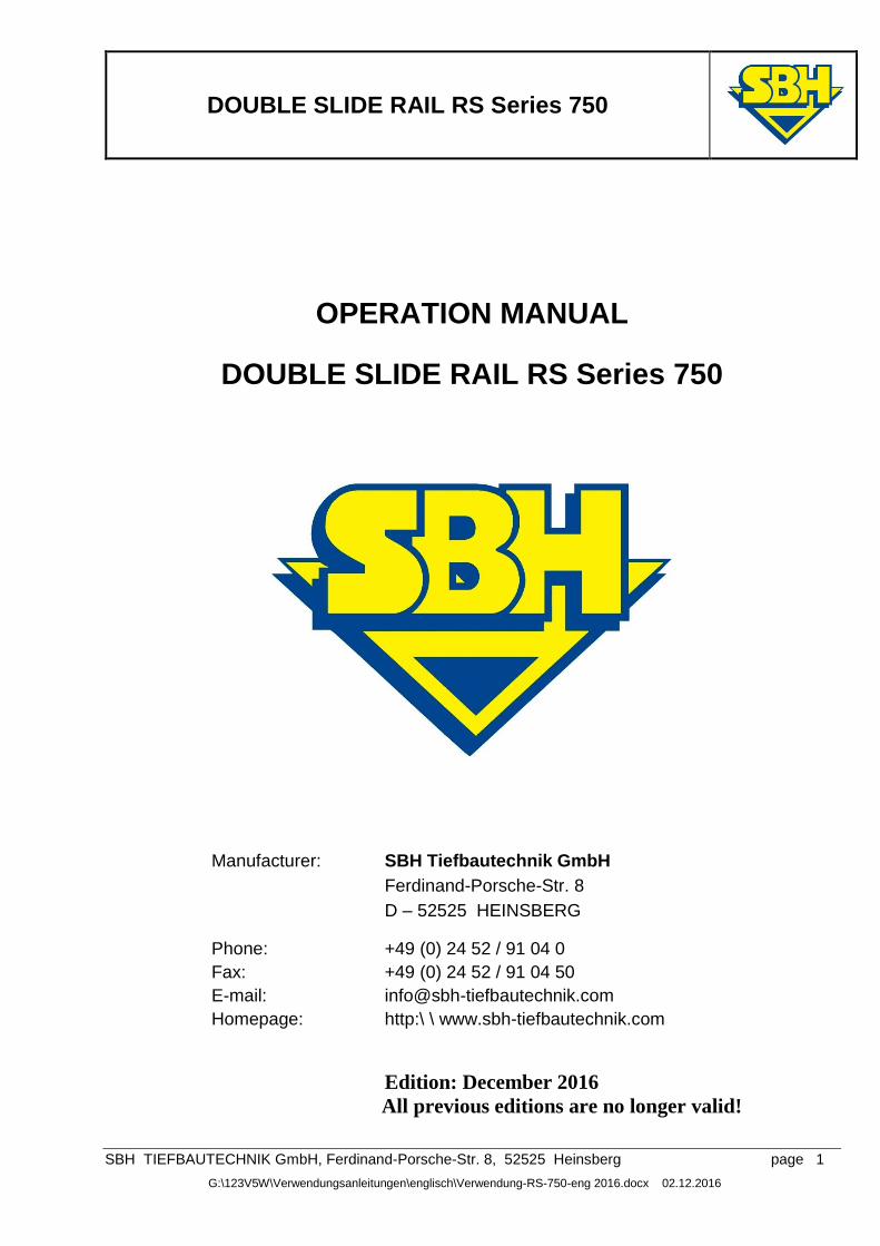
DOUBLE SLIDE RAIL RS Series 750
SBH TIEFBAUTECHNIK GmbH, Ferdinand-Porsche-Str. 8, 52525 Heinsberg page 1
G:\123V5W\Verwendungsanleitungen\englisch\Verwendung-RS-750-eng 2016.docx 02.12.2016
OPERATION MANUAL
DOUBLE SLIDE RAIL RS Series 750
Manufacturer: SBH Tiefbautechnik GmbH
Ferdinand-Porsche-Str. 8
D – 52525 HEINSBERG
Phone: +49 (0) 24 52 / 91 04 0
Fax: +49 (0) 24 52 / 91 04 50
E-mail: [email protected]
Homepage: http:\ \ www.sbh-tiefbautechnik.com
Edition: December 2016
All previous editions are no longer valid!
DOUBLE SLIDE RAIL RS Series 750
SBH TIEFBAUTECHNIK GmbH, Ferdinand-Porsche-Str. 8, 52525 Heinsberg page 2
G:\123V5W\Verwendungsanleitungen\englisch\Verwendung-RS-750-eng 2016.docx 02.12.2016
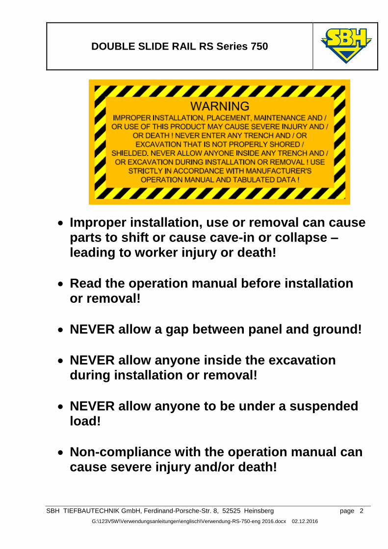
Improper installation, use or removal can cause parts to shift or cause cave-in or collapse – leading to worker injury or death!
Read the operation manual before installation or removal!
NEVER allow a gap between panel and ground!
NEVER allow anyone inside the excavation during installation or removal!
NEVER allow anyone to be under a suspended load!
Non-compliance with the operation manual can cause severe injury and/or death!
DOUBLE SLIDE RAIL RS Series 750
SBH TIEFBAUTECHNIK GmbH, Ferdinand-Porsche-Str. 8, 52525 Heinsberg page 3
G:\123V5W\Verwendungsanleitungen\englisch\Verwendung-RS-750-eng 2016.docx 02.12.2016
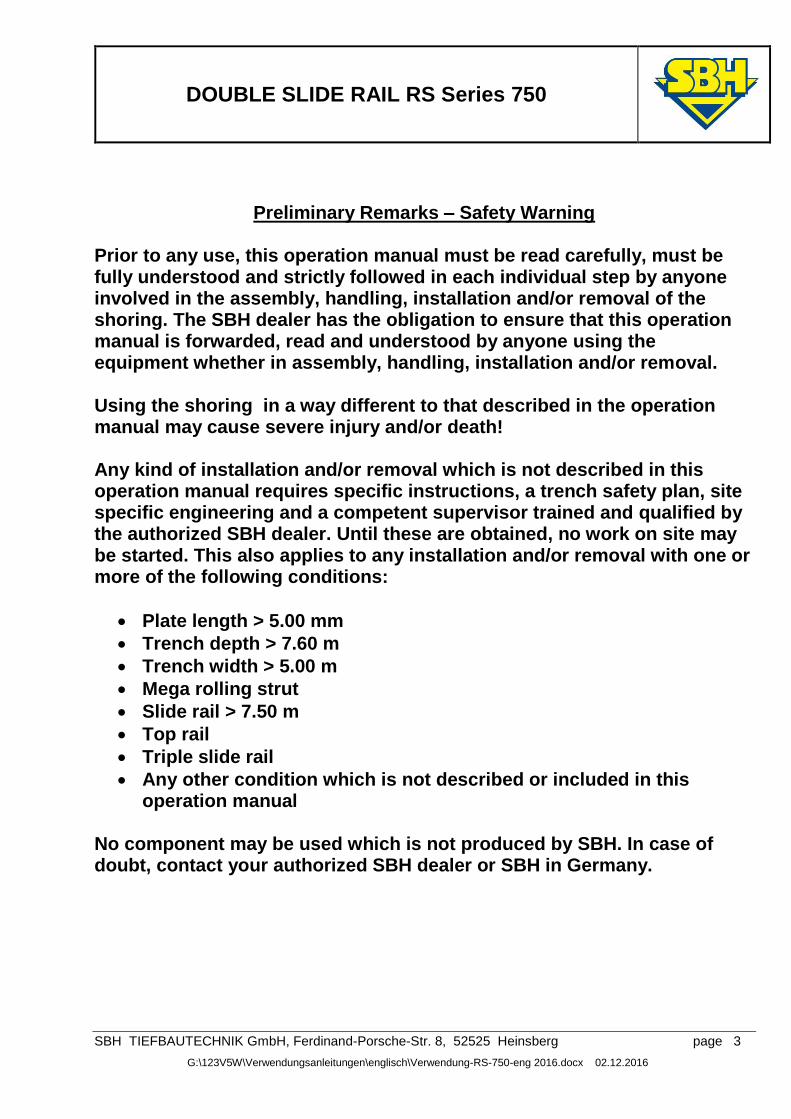
Preliminary Remarks – Safety Warning
Prior to any use, this operation manual must be read carefully, must be fully understood and strictly followed in each individual step by anyone involved in the assembly, handling, installation and/or removal of the shoring. The SBH dealer has the obligation to ensure that this operation manual is forwarded, read and understood by anyone using the equipment whether in assembly, handling, installation and/or removal. Using the shoring in a way different to that described in the operation manual may cause severe injury and/or death! Any kind of installation and/or removal which is not described in this operation manual requires specific instructions, a trench safety plan, site specific engineering and a competent supervisor trained and qualified by the authorized SBH dealer. Until these are obtained, no work on site may be started. This also applies to any installation and/or removal with one or more of the following conditions:
Plate length > 5.00 mm
Trench depth > 7.60 m
Trench width > 5.00 m
Mega rolling strut
Slide rail > 7.50 m
Top rail
Triple slide rail
Any other condition which is not described or included in this operation manual
No component may be used which is not produced by SBH. In case of doubt, contact your authorized SBH dealer or SBH in Germany.
DOUBLE SLIDE RAIL RS Series 750
SBH TIEFBAUTECHNIK GmbH, Ferdinand-Porsche-Str. 8, 52525 Heinsberg page 4
G:\123V5W\Verwendungsanleitungen\englisch\Verwendung-RS-750-eng 2016.docx 02.12.2016
Contents
General instructions
Lifting & transporting 5
Measures to reduce hazards 5
Maintenance & repair 6
Technical description 7
System drawings
Mini - RS 8
Standard - RS 9
Mega - RS 10
Technical parameters
Shoring plates 11
Rolling struts (RS) and distance pieces 12
RS slide rails 13
Accessories 14
Assembly instructions 15
Assembly help 17
Assembly of top rails 17
Installation instructions
Permitted tensile forces 18
Alignment of the initial shoring bay 18
Installation of top rails 19
Removal 23
Bottom support 24
Adjustable clamping device
System drawing 25
Technical parameters 26
Installation instructions 26
Shafts
System drawing 27
Installation instructions 28
Installation of top rails 30
DOUBLE SLIDE RAIL RS Series 750
SBH TIEFBAUTECHNIK GmbH, Ferdinand-Porsche-Str. 8, 52525 Heinsberg page 5
G:\123V5W\Verwendungsanleitungen\englisch\Verwendung-RS-750-eng 2016.docx 02.12.2016
General instructions The double slide rail RS series 750 is strictly and exclusively authorised for the dig and push method (also known as cut and lower method). The shoring must be without gap and close to the ground. Gaps are NOT permitted behind the plates! The limiting values for the max. loads are to be observed strictly. Single shoring sections (boxes) may only be used if the front and rear faces are properly secured.
The folllowing rules and regulations are to be applied in their respective valid version:
Regulations of the BG-Fachausschuss Tiefbau (Technical Commitee Civil Engineering)
DIN 4124 Baugruben und Gräben (Excavation pits and trenches) [Not available in English]
DIN EN 13331 Part 1 & 2 Trench lining systems (Part 1: Product specifications; Part 2: Assessment by calculation or test)
Regeln für Sicherheit und Gesundheit bei der Arbeit (German rules for safety and health at work)
Unfallverhütungsvorschriften / Arbeitsschutzvorschriften (German accident prevention regulations / Health and safety at work regulations)
Local rules and regulations in their valid version, e.g. OSHA regulations for US market
Our shoring components carry the GS-Sign “Certified Safety”.
For assembly, installation and removal, the instructions of this operation manual are to be followed.
Lifting & Transporting
The shoring may only be attached at the designated eyes and openings and/or lifting accessories.
The lifting accessories must be adjusted to the weight which is to be transported.
For safety reasons, load hooks with hook safety must be used exclusively.
The permitted tensile forces are to be observed without exception.
The transporting is to be carried out as close as possible to the ground and unnecessary pendulum movements are to be avoided.
It is forbidden to enter the swivel range of the lifting device and to stay under suspended loads.
Attention is to be paid to overhead electrical lines.
Eye contact is to be maintained between machine operator and banksman.
Measures to reduce hazards
The construction site is to be secured and signed adequately.
Neighbouring traffic flow is to be ensured, if necessary through additional security personnel.
All personnel are to wear protective clothing (helmet / safety shoes / gloves).
Possible instabilities as a result of wind loads during assembly and installation, are to be taken into account.
Store shoring components as far as possible horizontal on firm ground.
In the case of slopes particular attention is to be paid to the stable storage of pre-assembled components.
DOUBLE SLIDE RAIL RS Series 750
SBH TIEFBAUTECHNIK GmbH, Ferdinand-Porsche-Str. 8, 52525 Heinsberg page 6
G:\123V5W\Verwendungsanleitungen\englisch\Verwendung-RS-750-eng 2016.docx 02.12.2016
Maintenance & repair
As a matter of principle, the operability of all shoring components must be checked before use. Prior to use, ensure a thorough visual inspection of all components by a competent person. In case of doubt, contact your authorized SBH dealer.
Defective or deformed components may not be employed.
Repairs are to be carried out by your authorized SBH dealer or by SBH Germany only. Own repairs are not permitted.
Use only original spare parts from SBH.
Depending on the intensity of use, components should be painted with anti-corrosive paint every 2 years.
DOUBLE SLIDE RAIL RS Series 750
SBH TIEFBAUTECHNIK GmbH, Ferdinand-Porsche-Str. 8, 52525 Heinsberg page 7
G:\123V5W\Verwendungsanleitungen\englisch\Verwendung-RS-750-eng 2016.docx 02.12.2016
Technical description
end-supported, slide rail guided shoring
for trench depths down to 7.60 m without top rail
for trench depths down to 9.00 m with top rail
in plate lengths up to 6.00 m
in plate heights of 2.40 m
in top plate heights of 1.40 m
for working widths up to 6.24 m
The great advantages of this system:
Easy installation and removal, since plates, rails and rolling struts can be positioned individually
Continuously variable adjustment of strut clearance heights
Robust distance pieces in 0.25 / 0.50 / 0.75 / 1.00 / 2.00 & 3.00 m Upon request we would be happy also to manufacture special dimensions.
easy flange-mounting of the distance pieces using M30 bolts of quality 10.9
DOUBLE SLIDE RAIL RS Series 750
SBH TIEFBAUTECHNIK GmbH, Ferdinand-Porsche-Str. 8, 52525 Heinsberg page 8
G:\123V5W\Verwendungsanleitungen\englisch\Verwendung-RS-750-eng 2016.docx 02.12.2016
System drawing: Mini - RS I Slide rail II Rolling Strut (RS) III Distance piece IV Limit pin V Bolting M30 VI Base plate b Trench width
bC Working width bRS Rolling Strut width bT Slide rail height = type hC Strut clearance height hF Flange height L Plate height LS System length
LC Pipe clearance length LRS Rolling strut length LT Slide rail length LZ Distance piece length
DOUBLE SLIDE RAIL RS Series 750
SBH TIEFBAUTECHNIK GmbH, Ferdinand-Porsche-Str. 8, 52525 Heinsberg page 9
G:\123V5W\Verwendungsanleitungen\englisch\Verwendung-RS-750-eng 2016.docx 02.12.2016
System drawing: Standard - RS
I Slide rail II Rolling Strut (RS) III Distance piece IV Limit pin V Bolting M30 VI Base plate
b Trench width bC Working width bRS Rolling Strut width bT Slide rail height = type hC Strut clearance height hF Flange height L Plate height
LS System length LC Pipe clearance length LRS Rolling strut length LT Slide rail length LZ Distance piece length
VII Top plate
DOUBLE SLIDE RAIL RS Series 750
SBH TIEFBAUTECHNIK GmbH, Ferdinand-Porsche-Str. 8, 52525 Heinsberg page 10
G:\123V5W\Verwendungsanleitungen\englisch\Verwendung-RS-750-eng 2016.docx 02.12.2016
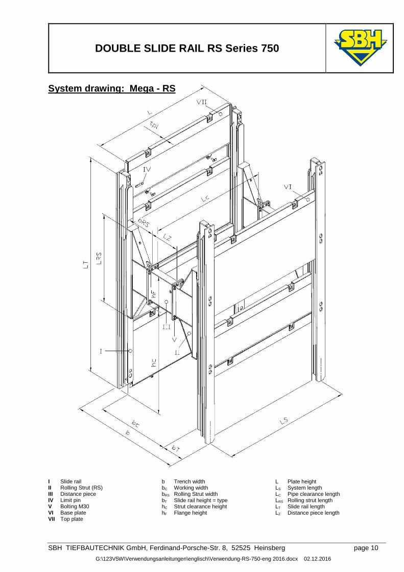
System drawing: Mega - RS
I Slide rail II Rolling Strut (RS) III Distance piece IV Limit pin V Bolting M30 VI Base plate
b Trench width bC Working width bRS Rolling Strut width bT Slide rail height = type hC Strut clearance height hF Flange height
L Plate height LS System length LC Pipe clearance length LRS Rolling strut length LT Slide rail length LZ Distance piece length
VII Top plate
DOUBLE SLIDE RAIL RS Series 750
SBH TIEFBAUTECHNIK GmbH, Ferdinand-Porsche-Str. 8, 52525 Heinsberg page 11
G:\123V5W\Verwendungsanleitungen\englisch\Verwendung-RS-750-eng 2016.docx 02.12.2016
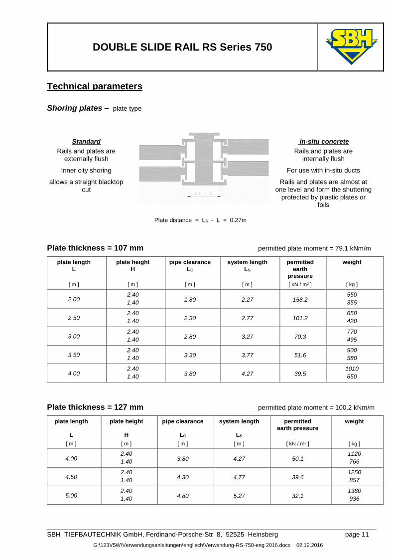
Technical parameters
Shoring plates – plate type
Standard
in-situ concrete
Rails and plates are externally flush
Rails and plates are internally flush
Inner city shoring For use with in-situ ducts
allows a straight blacktop cut
Rails and plates are almost at one level and form the shuttering
protected by plastic plates or foils
Plate distance = LS - L = 0.27m
Plate thickness = 107 mm permitted plate moment = 79.1 kNm/m
plate length plate height pipe clearance system length permitted weight
L H LC LS earth pressure
[ m ] [ m ] [ m ] [ m ] [ kN / m² ] [ kg ]
2.00 2.40
1.80 2.27 158.2 550
1.40 355
2.50 2.40
2.30 2.77 101.2 650
1.40 420
3.00 2.40
2.80 3.27 70.3 770
1.40 495
3.50 2.40
3.30 3.77 51.6 900
1.40 580
4.00 2.40
3.80 4.27 39.5 1010
1.40 650
Plate thickness = 127 mm permitted plate moment = 100.2 kNm/m
plate length plate height pipe clearance system length permitted earth pressure
weight
L H LC LS
[ m ] [ m ] [ m ] [ m ] [ kN / m² ] [ kg ]
4.00 2.40
3.80 4.27 50.1 1120
1.40 766
4.50 2.40
4.30 4.77 39.6 1250
1.40 857
5.00 2.40
4.80 5.27 32,1 1380
1,40 936
DOUBLE SLIDE RAIL RS Series 750
SBH TIEFBAUTECHNIK GmbH, Ferdinand-Porsche-Str. 8, 52525 Heinsberg page 12
G:\123V5W\Verwendungsanleitungen\englisch\Verwendung-RS-750-eng 2016.docx 02.12.2016
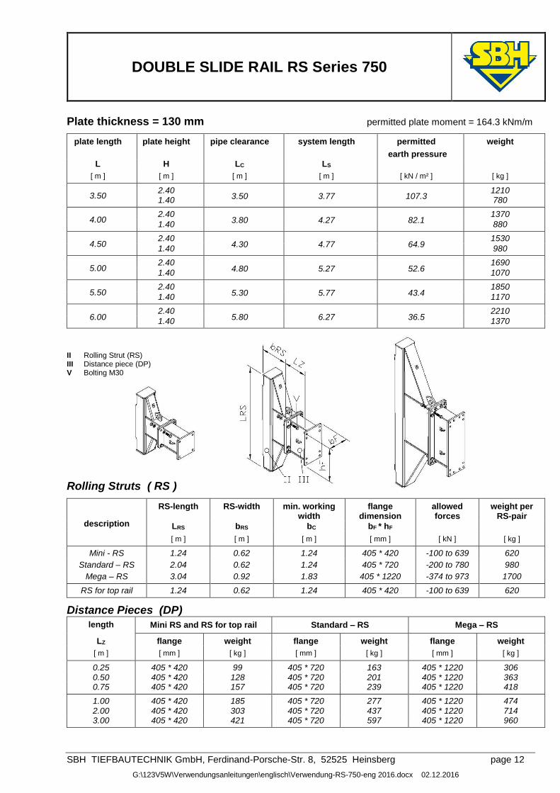
Plate thickness = 130 mm permitted plate moment = 164.3 kNm/m
plate length plate height pipe clearance system length permitted
earth pressure
weight
L H LC LS
[ m ] [ m ] [ m ] [ m ] [ kN / m² ] [ kg ]
3.50 2.40 1.40 3.50 3.77 107.3
1210 780
4.00 2.40
3.80 4.27 82.1 1370
1.40 880
4.50 2.40
4.30 4.77 64.9 1530
1.40 980
5.00 2.40
4.80 5.27 52.6 1690
1.40 1070
5.50 2.40
5.30 5.77 43.4 1850
1.40 1170
6.00 2.40
5.80 6.27 36.5 2210
1.40 1370
II Rolling Strut (RS) III Distance piece (DP) V Bolting M30
Rolling Struts ( RS )
description
RS-length RS-width min. working width
flange dimension
allowed forces
weight per RS-pair
LRS bRS bC bF * hF
[ m ] [ m ] [ m ] [ mm ] [ kN ] [ kg ]
Mini - RS 1.24 0.62 1.24 405 * 420 -100 to 639 620
Standard – RS 2.04 0.62 1.24 405 * 720 -200 to 780 980
Mega – RS 3.04 0.92 1.83 405 * 1220 -374 to 973 1700
RS for top rail 1.24 0.62 1.24 405 * 420 -100 to 639 620
Distance Pieces (DP)
length Mini RS and RS for top rail Standard – RS Mega – RS
LZ flange weight flange weight flange weight
[ m ] [ mm ] [ kg ] [ mm ] [ kg ] [ mm ] [ kg ]
0.25 405 * 420 99 405 * 720 163 405 * 1220 306 0.50 405 * 420 128 405 * 720 201 405 * 1220 363 0.75 405 * 420 157 405 * 720 239 405 * 1220 418
1.00 405 * 420 185 405 * 720 277 405 * 1220 474 2.00 405 * 420 303 405 * 720 437 405 * 1220 714 3.00 405 * 420 421 405 * 720 597 405 * 1220 960
DOUBLE SLIDE RAIL RS Series 750
SBH TIEFBAUTECHNIK GmbH, Ferdinand-Porsche-Str. 8, 52525 Heinsberg page 13
G:\123V5W\Verwendungsanleitungen\englisch\Verwendung-RS-750-eng 2016.docx 02.12.2016
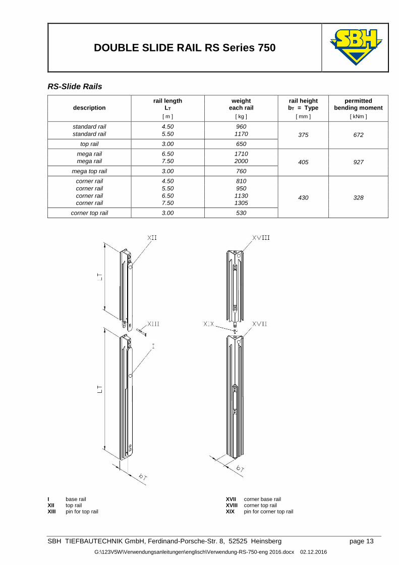
RS-Slide Rails
rail length weight rail height permitted description LT each rail bT = Type bending moment
[ m ] [ kg ] [ mm ] [ kNm ]
standard rail 4.50 960
375
672 standard rail 5.50 1170
top rail 3.00 650
mega rail 6.50 1710
405
927 mega rail 7.50 2000
mega top rail 3.00 760
corner rail 4.50 810
430
328
corner rail 5.50 950
corner rail 6.50 1130
corner rail 7.50 1305
corner top rail 3.00 530
I base rail XII top rail XIII pin for top rail
XVII corner base rail XVIII corner top rail XIX pin for corner top rail
DOUBLE SLIDE RAIL RS Series 750
SBH TIEFBAUTECHNIK GmbH, Ferdinand-Porsche-Str. 8, 52525 Heinsberg page 14
G:\123V5W\Verwendungsanleitungen\englisch\Verwendung-RS-750-eng 2016.docx 02.12.2016
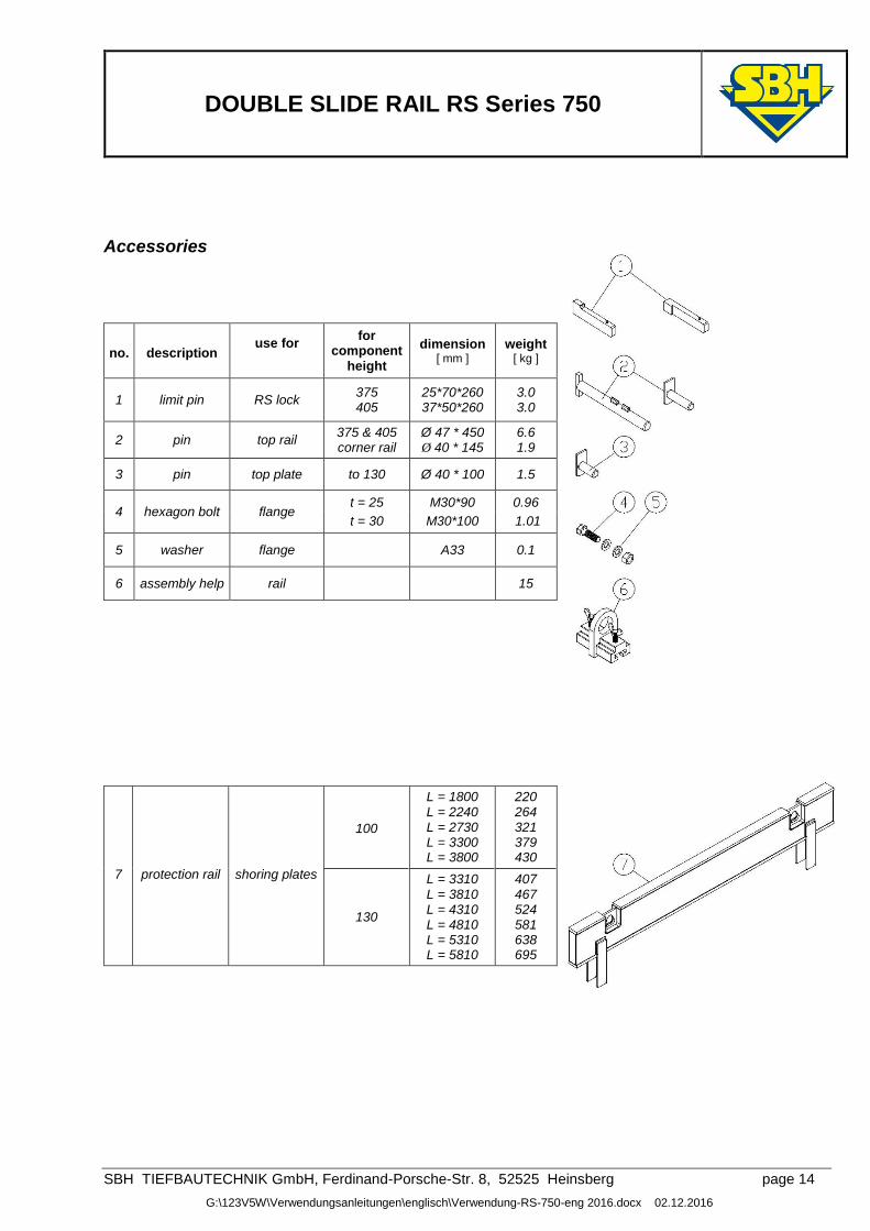
Accessories
no. description use for
for component
height
dimension [ mm ]
weight [ kg ]
1 limit pin RS lock 375 405
25*70*260 37*50*260
3.0 3.0
2 pin top rail 375 & 405 corner rail
Ø 47 * 450 Ø 40 * 145
6.6 1.9
3 pin top plate to 130 Ø 40 * 100 1.5
4 hexagon bolt flange t = 25 M30*90 0.96
t = 30 M30*100 1.01
5 washer flange A33 0.1
6 assembly help rail 15
7 protection rail shoring plates
100
L = 1800 L = 2240 L = 2730 L = 3300 L = 3800
220 264 321 379 430
130
L = 3310 L = 3810 L = 4310 L = 4810 L = 5310 L = 5810
407 467 524 581 638 695
DOUBLE SLIDE RAIL RS Series 750
SBH TIEFBAUTECHNIK GmbH, Ferdinand-Porsche-Str. 8, 52525 Heinsberg page 15
G:\123V5W\Verwendungsanleitungen\englisch\Verwendung-RS-750-eng 2016.docx 02.12.2016
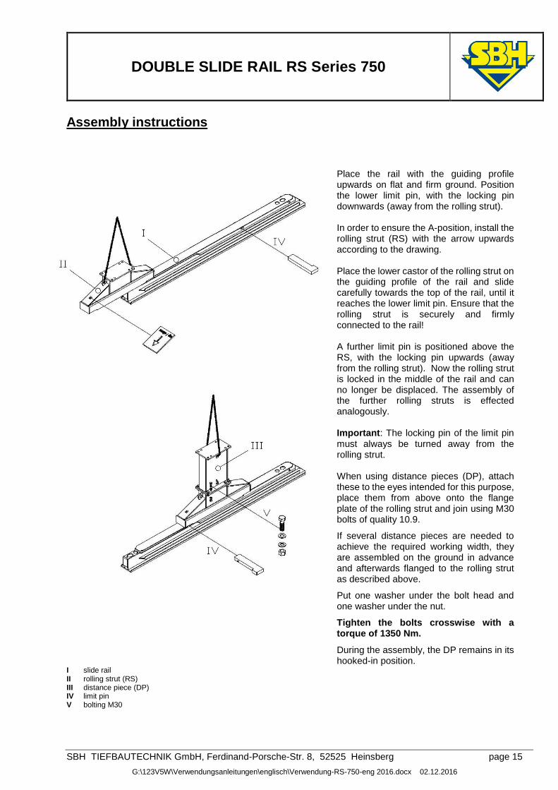
Assembly instructions
Place the rail with the guiding profile upwards on flat and firm ground. Position the lower limit pin, with the locking pin downwards (away from the rolling strut). In order to ensure the A-position, install the rolling strut (RS) with the arrow upwards according to the drawing. Place the lower castor of the rolling strut on the guiding profile of the rail and slide carefully towards the top of the rail, until it reaches the lower limit pin. Ensure that the rolling strut is securely and firmly connected to the rail! A further limit pin is positioned above the RS, with the locking pin upwards (away from the rolling strut). Now the rolling strut is locked in the middle of the rail and can no longer be displaced. The assembly of the further rolling struts is effected analogously. Important: The locking pin of the limit pin must always be turned away from the rolling strut. When using distance pieces (DP), attach these to the eyes intended for this purpose, place them from above onto the flange plate of the rolling strut and join using M30 bolts of quality 10.9.
If several distance pieces are needed to achieve the required working width, they are assembled on the ground in advance and afterwards flanged to the rolling strut as described above.
Put one washer under the bolt head and one washer under the nut.
Tighten the bolts crosswise with a torque of 1350 Nm.
During the assembly, the DP remains in its hooked-in position.
I slide rail II rolling strut (RS) III distance piece (DP) IV limit pin V bolting M30
DOUBLE SLIDE RAIL RS Series 750
SBH TIEFBAUTECHNIK GmbH, Ferdinand-Porsche-Str. 8, 52525 Heinsberg page 16
G:\123V5W\Verwendungsanleitungen\englisch\Verwendung-RS-750-eng 2016.docx 02.12.2016
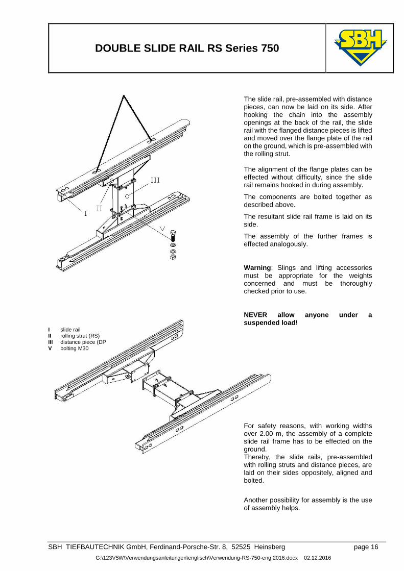
The slide rail, pre-assembled with distance pieces, can now be laid on its side. After hooking the chain into the assembly openings at the back of the rail, the slide rail with the flanged distance pieces is lifted and moved over the flange plate of the rail on the ground, which is pre-assembled with the rolling strut. The alignment of the flange plates can be effected without difficulty, since the slide rail remains hooked in during assembly.
The components are bolted together as described above.
The resultant slide rail frame is laid on its side.
The assembly of the further frames is effected analogously.
Warning: Slings and lifting accessories must be appropriate for the weights concerned and must be thoroughly checked prior to use.
NEVER allow anyone under a suspended load!
I slide rail II rolling strut (RS) III distance piece (DP V bolting M30
For safety reasons, with working widths over 2.00 m, the assembly of a complete slide rail frame has to be effected on the ground. Thereby, the slide rails, pre-assembled with rolling struts and distance pieces, are laid on their sides oppositely, aligned and bolted.
Another possibility for assembly is the use of assembly helps.
DOUBLE SLIDE RAIL RS Series 750
SBH TIEFBAUTECHNIK GmbH, Ferdinand-Porsche-Str. 8, 52525 Heinsberg page 17
G:\123V5W\Verwendungsanleitungen\englisch\Verwendung-RS-750-eng 2016.docx 02.12.2016
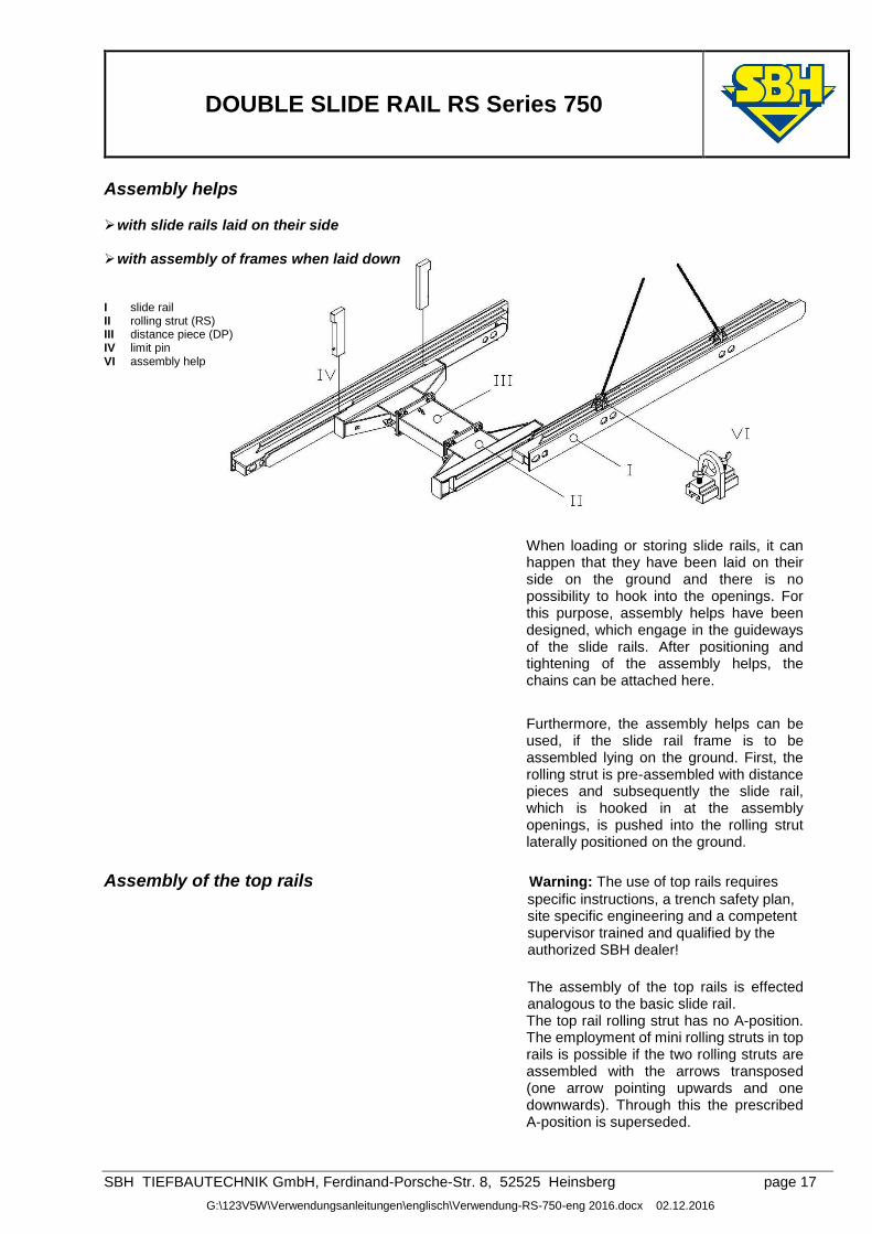
Assembly helps
with slide rails laid on their side
with assembly of frames when laid down I slide rail II rolling strut (RS) III distance piece (DP) IV limit pin VI assembly help
When loading or storing slide rails, it can happen that they have been laid on their side on the ground and there is no possibility to hook into the openings. For this purpose, assembly helps have been designed, which engage in the guideways of the slide rails. After positioning and tightening of the assembly helps, the chains can be attached here.
Furthermore, the assembly helps can be used, if the slide rail frame is to be assembled lying on the ground. First, the rolling strut is pre-assembled with distance pieces and subsequently the slide rail, which is hooked in at the assembly openings, is pushed into the rolling strut laterally positioned on the ground.
Assembly of the top rails Warning: The use of top rails requires
specific instructions, a trench safety plan, site specific engineering and a competent supervisor trained and qualified by the authorized SBH dealer!
The assembly of the top rails is effected analogous to the basic slide rail.
The top rail rolling strut has no A-position. The employment of mini rolling struts in top rails is possible if the two rolling struts are assembled with the arrows transposed (one arrow pointing upwards and one downwards). Through this the prescribed A-position is superseded.
DOUBLE SLIDE RAIL RS Series 750
SBH TIEFBAUTECHNIK GmbH, Ferdinand-Porsche-Str. 8, 52525 Heinsberg page 18
G:\123V5W\Verwendungsanleitungen\englisch\Verwendung-RS-750-eng 2016.docx 02.12.2016
Installation instructions Warning: NEVER allow anyone to be inside excavations during installation! NEVER allow anyone under a suspended load! Non-compliance can cause severe injury and/or death!
Permitted tensile forces At the individual attachment points the
following tensile forces can be accepted:
slide rail
per lifting eye = 196 kN per guiding profile opening = 164 kN
plates
per lifting eye = 196 kN per eye at cutting edge = 49 kN
rolling strut
per lifting eye = 164 kN
distance piece
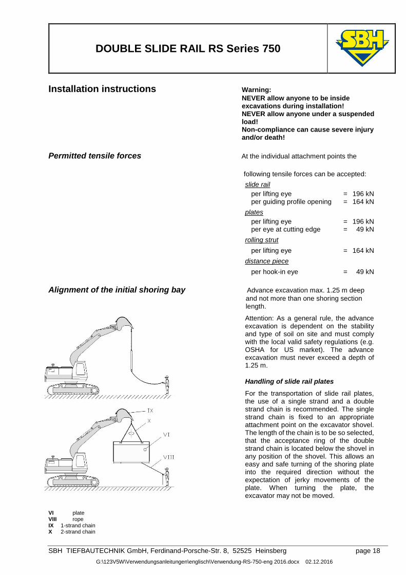
per hook-in eye = 49 kN Alignment of the initial shoring bay Advance excavation max. 1.25 m deep
and not more than one shoring section length.
Attention: As a general rule, the advance excavation is dependent on the stability and type of soil on site and must comply with the local valid safety regulations (e.g. OSHA for US market). The advance excavation must never exceed a depth of 1.25 m.
Handling of slide rail plates
For the transportation of slide rail plates, the use of a single strand and a double strand chain is recommended. The single strand chain is fixed to an appropriate attachment point on the excavator shovel. The length of the chain is to be so selected, that the acceptance ring of the double strand chain is located below the shovel in any position of the shovel. This allows an easy and safe turning of the shoring plate into the required direction without the expectation of jerky movements of the plate. When turning the plate, the excavator may not be moved.
VI plate VIII rope IX 1-strand chain X 2-strand chain
DOUBLE SLIDE RAIL RS Series 750
SBH TIEFBAUTECHNIK GmbH, Ferdinand-Porsche-Str. 8, 52525 Heinsberg page 19
G:\123V5W\Verwendungsanleitungen\englisch\Verwendung-RS-750-eng 2016.docx 02.12.2016
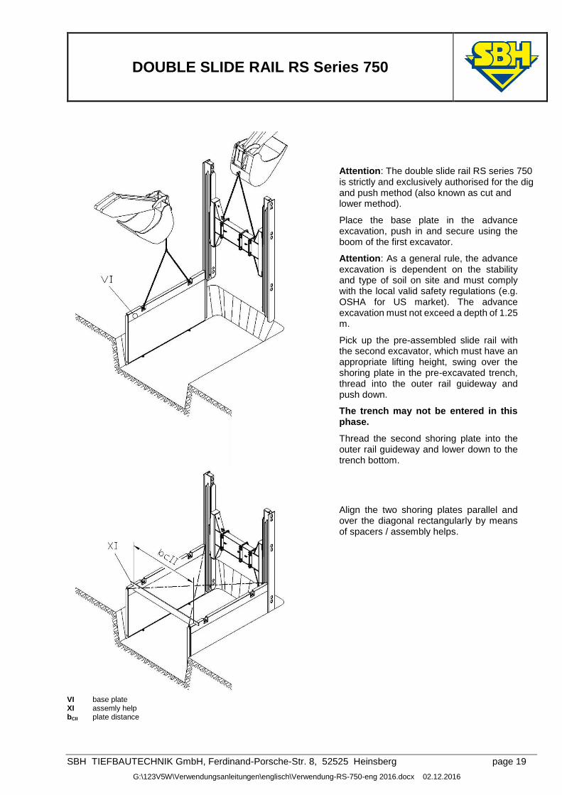
Attention: The double slide rail RS series 750 is strictly and exclusively authorised for the dig and push method (also known as cut and lower method).
Place the base plate in the advance excavation, push in and secure using the boom of the first excavator.
Attention: As a general rule, the advance excavation is dependent on the stability and type of soil on site and must comply with the local valid safety regulations (e.g. OSHA for US market). The advance excavation must not exceed a depth of 1.25 m.
Pick up the pre-assembled slide rail with the second excavator, which must have an appropriate lifting height, swing over the shoring plate in the pre-excavated trench, thread into the outer rail guideway and push down.
The trench may not be entered in this phase.
Thread the second shoring plate into the outer rail guideway and lower down to the trench bottom.
Align the two shoring plates parallel and over the diagonal rectangularly by means of spacers / assembly helps.
VI base plate XI assemly help bCII plate distance
DOUBLE SLIDE RAIL RS Series 750
SBH TIEFBAUTECHNIK GmbH, Ferdinand-Porsche-Str. 8, 52525 Heinsberg page 20
G:\123V5W\Verwendungsanleitungen\englisch\Verwendung-RS-750-eng 2016.docx 02.12.2016
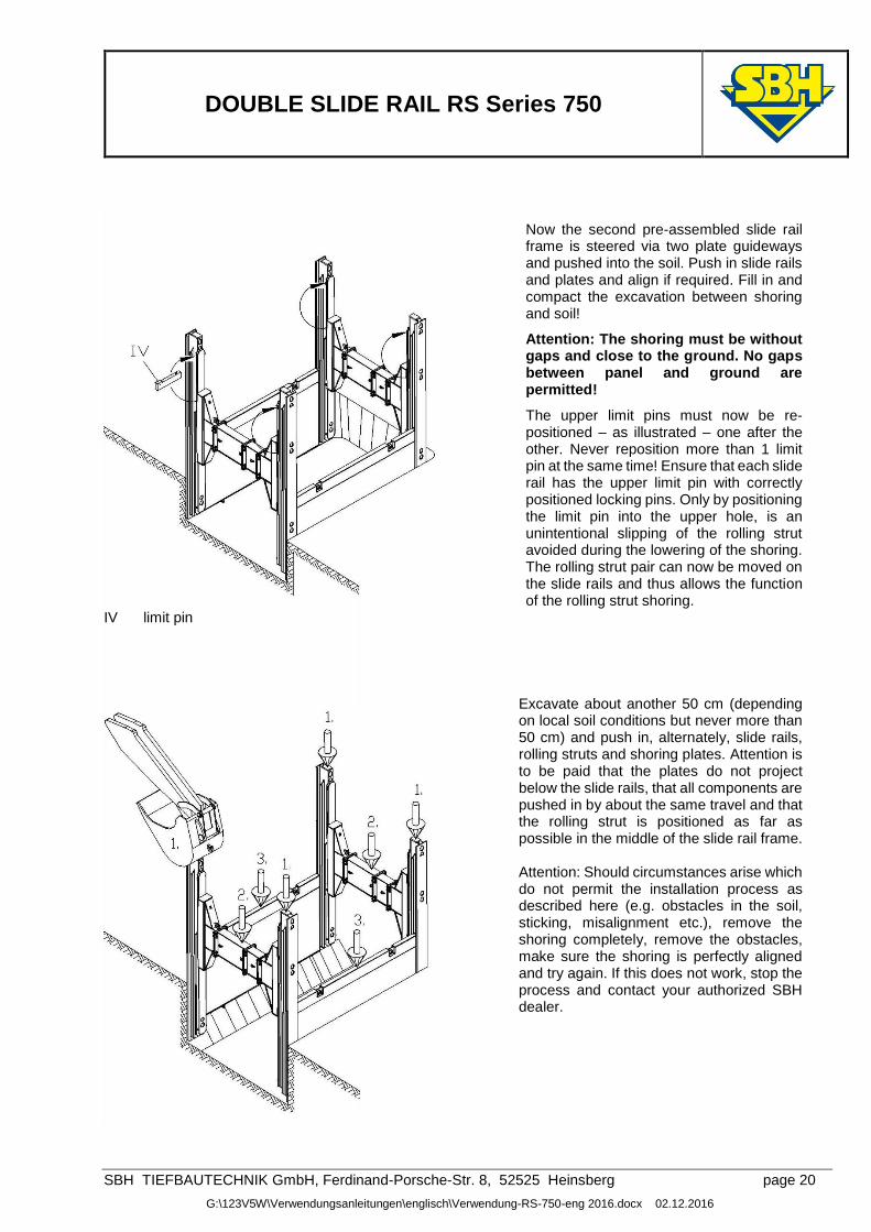
Now the second pre-assembled slide rail frame is steered via two plate guideways and pushed into the soil. Push in slide rails and plates and align if required. Fill in and compact the excavation between shoring and soil!
Attention: The shoring must be without gaps and close to the ground. No gaps between panel and ground are permitted!
The upper limit pins must now be re-positioned – as illustrated – one after the other. Never reposition more than 1 limit pin at the same time! Ensure that each slide rail has the upper limit pin with correctly positioned locking pins. Only by positioning the limit pin into the upper hole, is an unintentional slipping of the rolling strut avoided during the lowering of the shoring. The rolling strut pair can now be moved on the slide rails and thus allows the function of the rolling strut shoring.
IV limit pin
Excavate about another 50 cm (depending on local soil conditions but never more than 50 cm) and push in, alternately, slide rails, rolling struts and shoring plates. Attention is to be paid that the plates do not project below the slide rails, that all components are pushed in by about the same travel and that the rolling strut is positioned as far as possible in the middle of the slide rail frame. Attention: Should circumstances arise which do not permit the installation process as described here (e.g. obstacles in the soil, sticking, misalignment etc.), remove the shoring completely, remove the obstacles, make sure the shoring is perfectly aligned and try again. If this does not work, stop the process and contact your authorized SBH dealer.
DOUBLE SLIDE RAIL RS Series 750
SBH TIEFBAUTECHNIK GmbH, Ferdinand-Porsche-Str. 8, 52525 Heinsberg page 21
G:\123V5W\Verwendungsanleitungen\englisch\Verwendung-RS-750-eng 2016.docx 02.12.2016
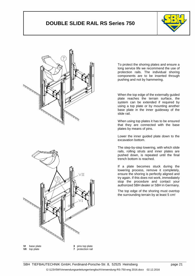
To protect the shoring plates and ensure a long service life we recommend the use of protection rails. The individual shoring components are to be inserted through pushing and not by hammering. When the top edge of the externally guided plate reaches the terrain surface, the system can be extended if required by using a top plate or by mounting another base plate in the inner guideway of the slide rail. When using top plates it has to be ensured that they are connected with the base plates by means of pins. Lower the inner guided plate down to the excavation bottom. The step-by-step lowering, with which slide rails, rolling struts and inner plates are pushed down, is repeated until the final trench bottom is reached. If a plate becomes stuck during the lowering process, remove it completely, ensure the shoring is perfectly aligned and try again. If this does not work, immediately stop the procedure and contact your authorized SBH dealer or SBH in Germany.
The top edge of the shoring must overtop the surrounding terrain by at least 5 cm!
VI base plate 3 pins top plate VII top plate 7 protection rail
DOUBLE SLIDE RAIL RS Series 750
SBH TIEFBAUTECHNIK GmbH, Ferdinand-Porsche-Str. 8, 52525 Heinsberg page 22
G:\123V5W\Verwendungsanleitungen\englisch\Verwendung-RS-750-eng 2016.docx 02.12.2016
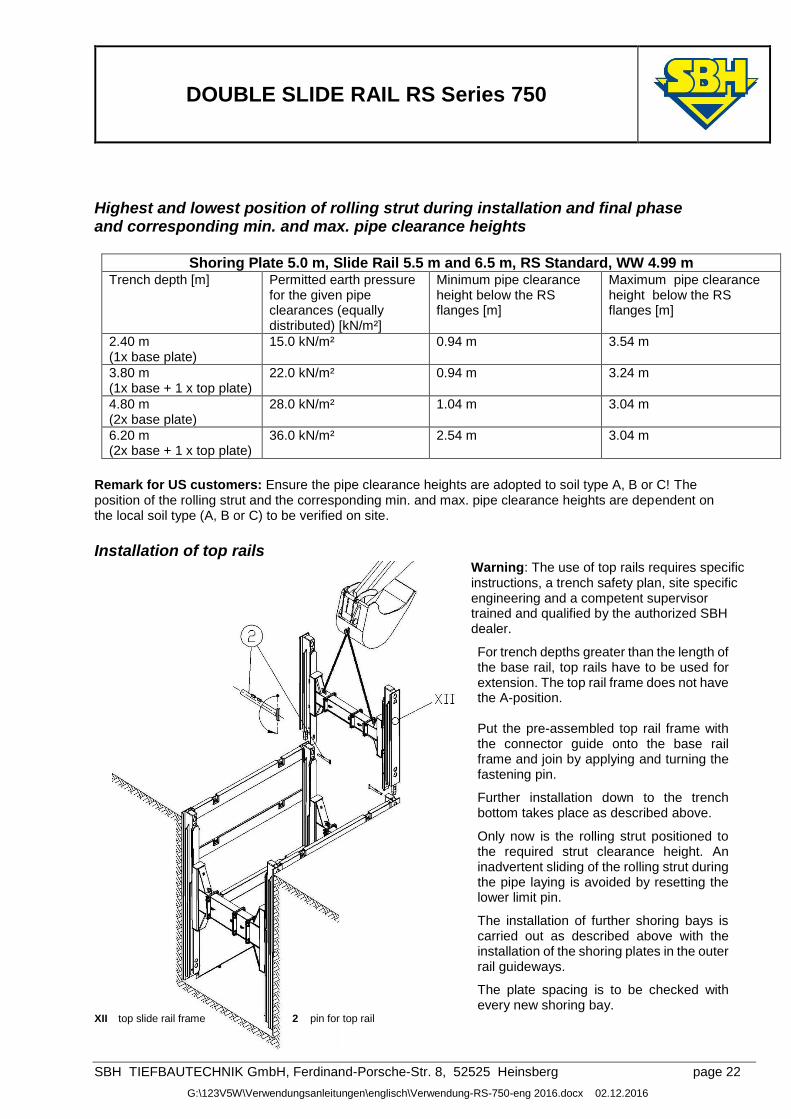
Highest and lowest position of rolling strut during installation and final phase and corresponding min. and max. pipe clearance heights
Shoring Plate 5.0 m, Slide Rail 5.5 m and 6.5 m, RS Standard, WW 4.99 m
Trench depth [m] Permitted earth pressure for the given pipe clearances (equally distributed) [kN/m²]
Minimum pipe clearance height below the RS flanges [m]
Maximum pipe clearance height below the RS flanges [m]
2.40 m (1x base plate)
15.0 kN/m² 0.94 m 3.54 m
3.80 m (1x base + 1 x top plate)
22.0 kN/m² 0.94 m 3.24 m
4.80 m (2x base plate)
28.0 kN/m² 1.04 m 3.04 m
6.20 m (2x base + 1 x top plate)
36.0 kN/m² 2.54 m 3.04 m
Remark for US customers: Ensure the pipe clearance heights are adopted to soil type A, B or C! The position of the rolling strut and the corresponding min. and max. pipe clearance heights are dependent on the local soil type (A, B or C) to be verified on site. Installation of top rails
Warning: The use of top rails requires specific instructions, a trench safety plan, site specific engineering and a competent supervisor trained and qualified by the authorized SBH dealer.
For trench depths greater than the length of the base rail, top rails have to be used for extension. The top rail frame does not have the A-position. Put the pre-assembled top rail frame with the connector guide onto the base rail frame and join by applying and turning the fastening pin.
Further installation down to the trench bottom takes place as described above.
Only now is the rolling strut positioned to the required strut clearance height. An inadvertent sliding of the rolling strut during the pipe laying is avoided by resetting the lower limit pin.
The installation of further shoring bays is carried out as described above with the installation of the shoring plates in the outer rail guideways.
The plate spacing is to be checked with every new shoring bay.
XII top slide rail frame 2 pin for top rail
DOUBLE SLIDE RAIL RS Series 750
SBH TIEFBAUTECHNIK GmbH, Ferdinand-Porsche-Str. 8, 52525 Heinsberg page 23
G:\123V5W\Verwendungsanleitungen\englisch\Verwendung-RS-750-eng 2016.docx 02.12.2016
Removal Warning: NEVER allow anyone to be inside excavations during installation! NEVER allow anyone under a suspended load! Non-compliance can cause severe injury and/or death!
At the beginning of the removal, remove the lower limit pins on the rolling strut. Depending on the compacting capabilities, fill in with max. 50 cm backfill.
Ensure that there is no gap between shoring and soil! No gaps between panel and ground are permitted! If present all gaps behind the plates must be filled.
Warning: Slings and lifting accessories must be appropriate for the weights and loads concerned and must be thoroughly checked prior to use.
NEVER allow anyone under a suspended load!
IV limit pin
Lift the shoring components (in the following order: plates, rolling struts and slide rails) to the filled height. Attention: Do not exceed a maximum of 50 cm! Lift the shoring plates side by side, never lift plates on opposite sides of the trench at the same time!
Finally compact the backfill.
Attention: Repeat this procedure as described until the shoring can be lifted out of the trench taking into account the safety instructions. Ensure that the shoring components are never lifted by more than 50 cm.! Use the designated lifting eyes only for lifting the shoring components.
We explicitly advise that it is not permitted to enter the danger area during both installation and removal.
Never allow anyone inside the trench during removal. It may cause severe injury and/or death!
Warning: If a shoring component gets stuck during the removal process, immediately stop the procedure and contact your authorized SBH dealer. Do not enter the trench! Entering the trench during removal may cause severe injury and/or death!
DOUBLE SLIDE RAIL RS Series 750
SBH TIEFBAUTECHNIK GmbH, Ferdinand-Porsche-Str. 8, 52525 Heinsberg page 24
G:\123V5W\Verwendungsanleitungen\englisch\Verwendung-RS-750-eng 2016.docx 02.12.2016
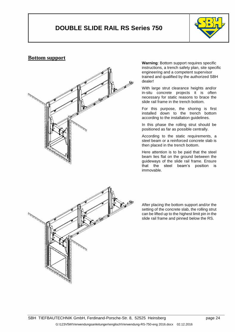
Bottom support
Warning: Bottom support requires specific instructions, a trench safety plan, site specific engineering and a competent supervisor trained and qualified by the authorized SBH dealer!
With large strut clearance heights and/or in-situ concrete projects it is often necessary for static reasons to brace the slide rail frame in the trench bottom.
For this purpose, the shoring is first installed down to the trench bottom according to the installation guidelines.
In this phase the rolling strut should be positioned as far as possible centrally.
According to the static requirements, a steel beam or a reinforced concrete slab is then placed in the trench bottom.
Here attention is to be paid that the steel beam lies flat on the ground between the guideways of the slide rail frame. Ensure that the steel beam’s position is immovable.
After placing the bottom support and/or the setting of the concrete slab, the rolling strut can be lifted up to the highest limit pin in the slide rail frame and pinned below the RS.
DOUBLE SLIDE RAIL RS Series 750
SBH TIEFBAUTECHNIK GmbH, Ferdinand-Porsche-Str. 8, 52525 Heinsberg page 25
G:\123V5W\Verwendungsanleitungen\englisch\Verwendung-RS-750-eng 2016.docx 02.12.2016
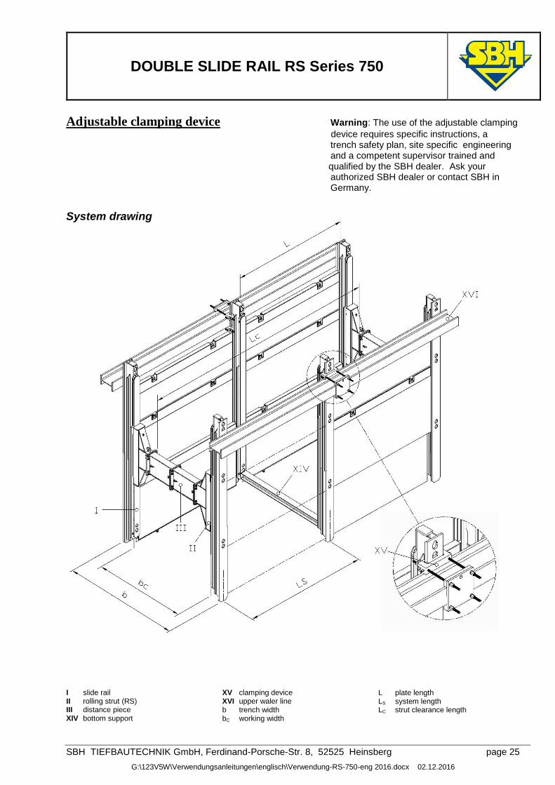
Adjustable clamping device Warning: The use of the adjustable clamping
device requires specific instructions, a trench safety plan, site specific engineering and a competent supervisor trained and
qualified by the SBH dealer. Ask your authorized SBH dealer or contact SBH in Germany.
System drawing I slide rail II rolling strut (RS) III distance piece XIV bottom support
XV clamping device XVI upper waler line b trench width bC working width
L plate length LS system length LC strut clearance length
DOUBLE SLIDE RAIL RS Series 750
SBH TIEFBAUTECHNIK GmbH, Ferdinand-Porsche-Str. 8, 52525 Heinsberg page 26
G:\123V5W\Verwendungsanleitungen\englisch\Verwendung-RS-750-eng 2016.docx 02.12.2016
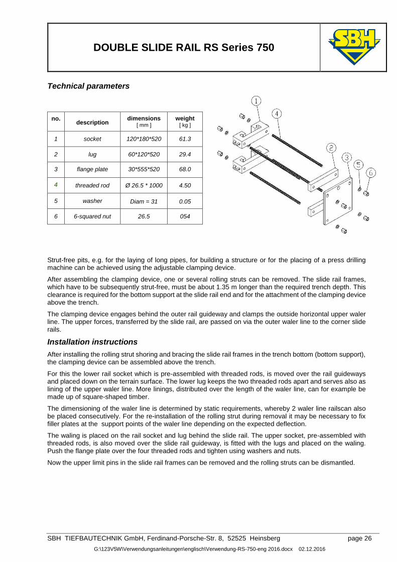
Technical parameters
no.
description
dimensions [ mm ]
weight [ kg ]
1 socket 120*180*520 61.3
2 lug 60*120*520 29.4
3 flange plate 30*555*520 68.0
4 threaded rod Ø 26.5 * 1000 4.50
5 washer Diam = 31 0.05
6 6-squared nut 26.5 054
Strut-free pits, e.g. for the laying of long pipes, for building a structure or for the placing of a press drilling machine can be achieved using the adjustable clamping device.
After assembling the clamping device, one or several rolling struts can be removed. The slide rail frames, which have to be subsequently strut-free, must be about 1.35 m longer than the required trench depth. This clearance is required for the bottom support at the slide rail end and for the attachment of the clamping device above the trench.
The clamping device engages behind the outer rail guideway and clamps the outside horizontal upper waler line. The upper forces, transferred by the slide rail, are passed on via the outer waler line to the corner slide rails.
Installation instructions
After installing the rolling strut shoring and bracing the slide rail frames in the trench bottom (bottom support), the clamping device can be assembled above the trench.
For this the lower rail socket which is pre-assembled with threaded rods, is moved over the rail guideways and placed down on the terrain surface. The lower lug keeps the two threaded rods apart and serves also as lining of the upper waler line. More linings, distributed over the length of the waler line, can for example be made up of square-shaped timber.
The dimensioning of the waler line is determined by static requirements, whereby 2 waler line railscan also be placed consecutively. For the re-installation of the rolling strut during removal it may be necessary to fix filler plates at the support points of the waler line depending on the expected deflection.
The waling is placed on the rail socket and lug behind the slide rail. The upper socket, pre-assembled with threaded rods, is also moved over the slide rail guideway, is fitted with the lugs and placed on the waling. Push the flange plate over the four threaded rods and tighten using washers and nuts.
Now the upper limit pins in the slide rail frames can be removed and the rolling struts can be dismantled.
DOUBLE SLIDE RAIL RS Series 750
SBH TIEFBAUTECHNIK GmbH, Ferdinand-Porsche-Str. 8, 52525 Heinsberg page 27
G:\123V5W\Verwendungsanleitungen\englisch\Verwendung-RS-750-eng 2016.docx 02.12.2016
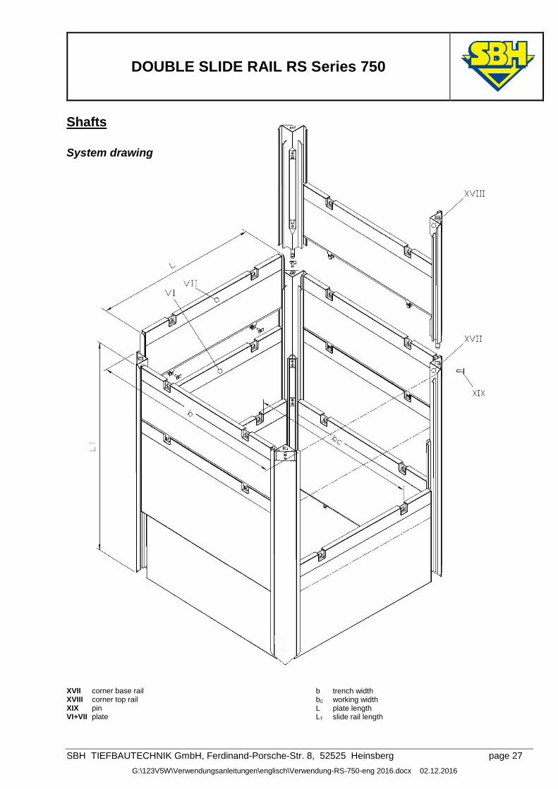
Shafts
System drawing
XVII corner base rail XVIII corner top rail XIX pin VI+VII plate
b trench width bC working width L plate length LT slide rail length
DOUBLE SLIDE RAIL RS Series 750
SBH TIEFBAUTECHNIK GmbH, Ferdinand-Porsche-Str. 8, 52525 Heinsberg page 28
G:\123V5W\Verwendungsanleitungen\englisch\Verwendung-RS-750-eng 2016.docx 02.12.2016
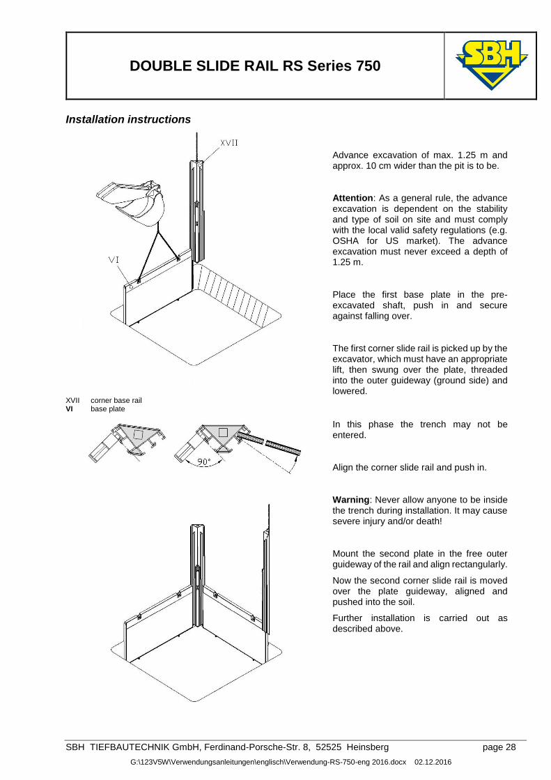
Installation instructions
Advance excavation of max. 1.25 m and approx. 10 cm wider than the pit is to be.
Attention: As a general rule, the advance excavation is dependent on the stability and type of soil on site and must comply with the local valid safety regulations (e.g. OSHA for US market). The advance excavation must never exceed a depth of 1.25 m.
Place the first base plate in the pre-excavated shaft, push in and secure against falling over.
The first corner slide rail is picked up by the excavator, which must have an appropriate lift, then swung over the plate, threaded into the outer guideway (ground side) and lowered.
XVII corner base rail VI base plate
In this phase the trench may not be entered.
Align the corner slide rail and push in.
Warning: Never allow anyone to be inside the trench during installation. It may cause severe injury and/or death!
Mount the second plate in the free outer guideway of the rail and align rectangularly.
Now the second corner slide rail is moved over the plate guideway, aligned and pushed into the soil.
Further installation is carried out as described above.
DOUBLE SLIDE RAIL RS Series 750
SBH TIEFBAUTECHNIK GmbH, Ferdinand-Porsche-Str. 8, 52525 Heinsberg page 29
G:\123V5W\Verwendungsanleitungen\englisch\Verwendung-RS-750-eng 2016.docx 02.12.2016
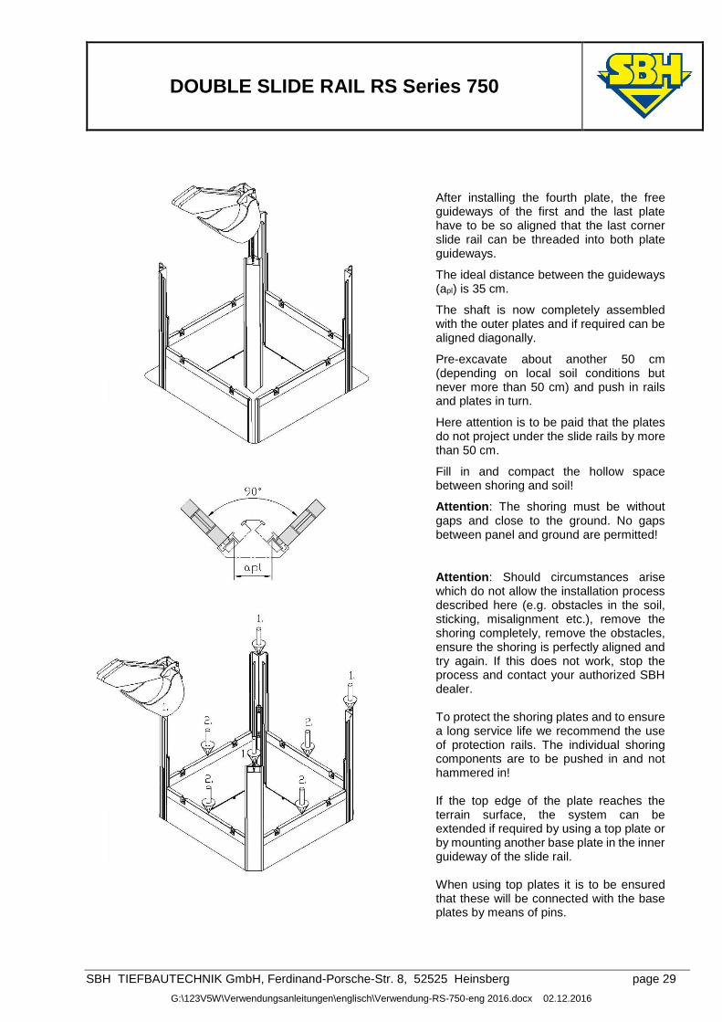
After installing the fourth plate, the free guideways of the first and the last plate have to be so aligned that the last corner slide rail can be threaded into both plate guideways.
The ideal distance between the guideways (apl) is 35 cm.
The shaft is now completely assembled with the outer plates and if required can be aligned diagonally.
Pre-excavate about another 50 cm (depending on local soil conditions but never more than 50 cm) and push in rails and plates in turn.
Here attention is to be paid that the plates do not project under the slide rails by more than 50 cm.
Fill in and compact the hollow space between shoring and soil!
Attention: The shoring must be without gaps and close to the ground. No gaps between panel and ground are permitted!
Attention: Should circumstances arise which do not allow the installation process described here (e.g. obstacles in the soil, sticking, misalignment etc.), remove the shoring completely, remove the obstacles, ensure the shoring is perfectly aligned and try again. If this does not work, stop the process and contact your authorized SBH dealer. To protect the shoring plates and to ensure a long service life we recommend the use of protection rails. The individual shoring components are to be pushed in and not hammered in! If the top edge of the plate reaches the terrain surface, the system can be extended if required by using a top plate or by mounting another base plate in the inner guideway of the slide rail. When using top plates it is to be ensured that these will be connected with the base plates by means of pins.
DOUBLE SLIDE RAIL RS Series 750
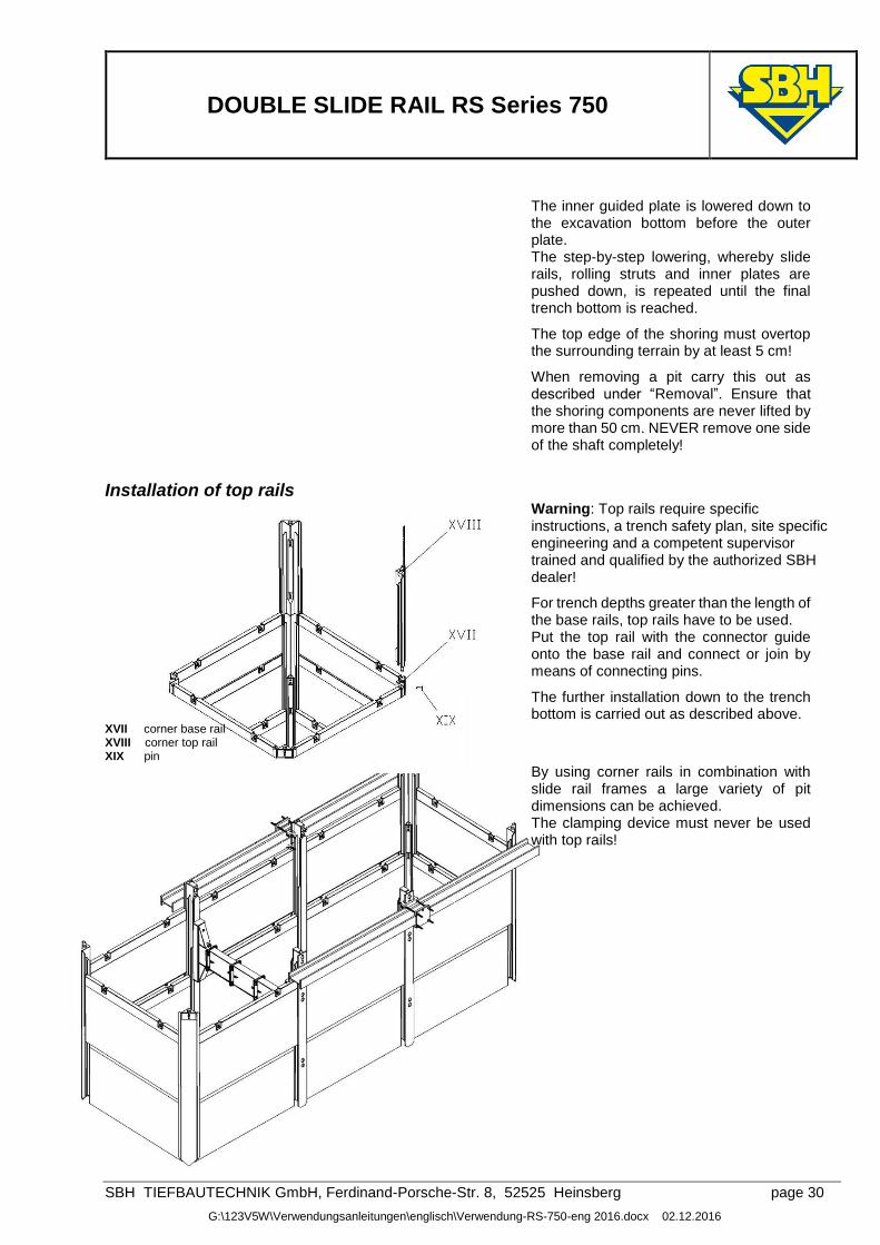
SBH TIEFBAUTECHNIK GmbH, Ferdinand-Porsche-Str. 8, 52525 Heinsberg page 30
G:\123V5W\Verwendungsanleitungen\englisch\Verwendung-RS-750-eng 2016.docx 02.12.2016
The inner guided plate is lowered down to the excavation bottom before the outer plate. The step-by-step lowering, whereby slide rails, rolling struts and inner plates are pushed down, is repeated until the final trench bottom is reached.
The top edge of the shoring must overtop the surrounding terrain by at least 5 cm!
When removing a pit carry this out as described under “Removal”. Ensure that the shoring components are never lifted by more than 50 cm. NEVER remove one side of the shaft completely!
Installation of top rails
Warning: Top rails require specific instructions, a trench safety plan, site specific engineering and a competent supervisor trained and qualified by the authorized SBH dealer!
For trench depths greater than the length of the base rails, top rails have to be used. Put the top rail with the connector guide onto the base rail and connect or join by means of connecting pins.
The further installation down to the trench bottom is carried out as described above.
XVII corner base rail XVIII corner top rail XIX pin
By using corner rails in combination with slide rail frames a large variety of pit dimensions can be achieved. The clamping device must never be used with top rails!