Embed Size (px)
Citation preview

G-862RBS
High Performance Base Station
Operation Manual
COPYRIGHT © MAR 2014
P/N 27922-OM Rev. B
GEOMETRICS, INC.
2190 Fortune Drive, San Jose, CA 95131 USA
Phone: (408) 954-0522
Fax: (408) 954-0902
We, Geometrics, Inc. Geometrics Europe 2190 Fortune Drive
San Jose, CA 95131 USA ph: (408) 954-0522 FAX: (408) 954-0902
declare under our sole responsibility that our marine magnetometers, models G-862 and G-862RBS to which this declaration relates are in conformity with the following standards: EN 55022: 1995, EN50082-2 : 1995, ENV 50140: 1994, ENV 50141 : 1994, EN 61000-4-2: 1995, EN 61000-4-4: 1995 per the provisions of the Electromagnetic Compatibility Directive 89/336/EEC of May 1989 as Amended by
92131/EEC of 28 April 1992 and 93/68-EEC, Article 5 of 22 July 1993.
The Technical documentation required by Annex IV(3) of the Low Voltage Directive is maintained by Christopher Leech of Geometrics Europe (address below). The authorized representative located within the Community is:
Geometrics Europe Christopher Leech 20 Eden Way Leighton Buzzard Beds LU7 4TZ, U.K. ph: +44 01525 383438 FAX: +44 01525 382200
Mark Prouty, President San Jose, CA, USA
CE March 14, 2003
Sunnyvale, California, USA
EC DECLARATION OF CONFORMITY
03

Warning
This is a Class A product. In a domestic environment this product may cause radio interference in which case the user may be required to take adequate measures.

G-862RBS Manual Operators Manual
Table of Contents
CHAPTER 1: INTRODUCTION ........................................................................... 4
Overview .................................................................................................................................................... 4
Applications ............................................................................................................................................... 5
Features ..................................................................................................................................................... 5
Open Source: ............................................................................................................................................. 6
Important Note Concerning Memory Sticks: ......................................................................................... 6
CHAPTER 2: INSTRUMENT ASSEMBLY ........................................................... 7
G-862RBS Assembly ................................................................................................................................. 7
Unpacking the G-862RBS ........................................................................................................................ 7
Attaching Sensor Bottle ............................................................................................................................ 9
Attaching Data Storage Box................................................................................................................... 11
Sensor Clamp .......................................................................................................................................... 12
Sensor Orientation .................................................................................................................................. 13
Cable Connections .................................................................................................................................. 20
CHAPTER 3: G-862RBS OPERATION .............................................................. 23
Turning on the System ........................................................................................................................... 23
The Processor Status Lights on the Front Panel: ................................................................................. 23
Logging Data with the Dogcatcher logging Module: ........................................................................... 24
Exchanging USB Thumb Drive ............................................................................................................. 25
Turning off the System ........................................................................................................................... 26
The Dogcatcher Logging Module Error Status Lights:....................................................................... 26
The Logged Data Format: ...................................................................................................................... 27
The Status Byte: ...................................................................................................................................... 29
GPS/Magnetometer Timing: .................................................................................................................. 32
Using the Bluetooth Port with an Android Phone/Tablet: ...................... Error! Bookmark not defined.

G-862RBS Manual Operators Manual
CHAPTER 4: MAGMONITOR SMARTPHONE APP ......................................... 39
Installation ............................................................................................................................................... 39
Bluetooth connection .............................................................................................................................. 40
Magnetometer Trace .............................................................................................................................. 42
GPS Track Plot ....................................................................................................................................... 44
GPS Serial Data Screen .......................................................................................................................... 45
Composite Screen.................................................................................................................................... 47
Settings ..................................................................................................................................................... 49
CHAPTER 5: DATA DOWNLOAD ..................................................................... 51
Read RBS data into MagMap2000. ....................................................................................................... 53
APPENDIX 1: G-862RBS CONFIGURATION .................................................... 57
Data Collection Set Up ........................................................................................................................... 57
G-862RBS Commands Via the Front Panel Monitor Port: ................................................................ 59
APPENDIX 2: GPS AND MAGNETOMETER PROGRAMMING ....................... 63
Overview .................................................................................................................................................. 63
Collecting GPS Data ............................................................................................................................... 63
Tallysman TW5310 GPS Setup ............................................................................................................. 64
G-862 Magnetometer Setup ................................................................................................................... 71
APPENDIX 3: CESIUM-VAPOR SENSOR THEORY ......................................... 73
APPENDIX 4: CSAZ ........................................................................................... 77
APPENDIX 5: INSTRUMENT SPECIFICATIONS .............................................. 78
Magnetometer: ......................................................................................................................................... 78
GPS Receiver ........................................................................................................................................... 78
Data Logger ............................................................................................................................................. 78
Mechanical / Environmental ................................................................................................................... 78

G-862RBS Manual Operators Manual
Power: ...................................................................................................................................................... 78
Standard Accessories: .............................................................................................................................. 78

G-862RBS Manual Operators Manual
Page 4 of 81
Chapter 1: Introduction
Overview
The model G-862RBS is a quality professional
magnetic base station tool offering the highest
performance base station recordings on the market
today. This system provides extremely accurate
magnetic readings at a high sample rate, stored on a
USB thumb drive recorder and sent to a computer or
external device for display through Bluetooth or RS-
232 connections. A GPS message is integrated into
the magnetic data to provide accurate time stamps that
are synced to a high degree of precision with a mobile
magnetometer using a GPS as well. This reduces the
need to sync the clocks on the base station and mobile
magnetometer instrument, and ensures a high degree
of accuracy when removing the diurnal variations in
the magnetic field during your survey.
Data is stored as a .TXT file on the USB
thumb drive or external device for quick entry into the MagMap2000 data software for applying
diurnal corrections to the survey data. The rate of data recording is fixed at 10 Hz sample rate.
Geometrics provide a 1 Gbyte USB thumb drive to store this base station data. A 1 Gbyte thumb
drive will allow for 22 days of continuous data at 10 Hz before needing to exchange thumb
drives.
The increased accuracy in synchronization between the mobile magnetometer system and
the base station will remove any phase differences in the data. This allows for a more robust
removal of time variations prominent in the surveying data, providing a more exact data set to
examine and process for publication.

G-862RBS Manual Operators Manual
Page 5 of 81
Applications
The G-862RBS has two potential purposes. The first purpose is to provide highly precise
and accurate magnetic readings for diurnal corrections to mobile magnetometers. A larger
storage space allows the magnetometer to record data at 10 Hz for weeks at a time without
needing to download. Synchronizing data streams of two instruments produces a more accurate
removal of the time variation seen in both instruments without introducing a phase shift
exhibited in poorly coordinated instrument clocks.
The second potential purpose is to act as a magnetic screening bench to test the magnetic
cleanliness of materials prior to survey. It is important to test any object that is located close to
the sensor during the survey for any magnetic properties so that it can be removed from the area.
If a screw or common instrument part is lost or missing it is possible to replace this piece. Any
part that is not supplied by Geometrics should be properly screened before use. Geometrics
screens each component separately to make sure only magnetically clean parts are used in the
sensor to ensure the highest quality data is possible.
Features
The G-862RBS is designed to greatly improve the quality and application of base station
data in all survey applications. Each feature is intended to more accurately record the magnetic
field strength at a single location as well as more precisely remove the time variations in the data
from a surveying magnetometer by synchronized time stamps using a GPS.
Continuous base station readings, where the unit automatically records data at a preset rate,
up to 10 magnetometer readings per second.
Integrated GPS data for accurate time stamps and exact coordination with a mobile
magnetometer also using a GPS device.
Storage capacity for more than 22 days of readings and positions at 10 Hz, each recorded
with the time of the event.

G-862RBS Manual Operators Manual
Page 6 of 81
Open Source:
This is something new for Geometrics. We have made the G-862 data logger box an
open source project. It uses an open source hardware platform (an Arduino Mega 2560 with a
RISC 32 bit processor), the Arduino open source development system, and open source libraries.
The schematics of the data logger and the source code (written in C) are available on our ftp site
at ftp:\\geom.geometrics.com/pub/mag/G862RBS. The schematic of the Arduino Mega 2560,
libraries, and development software are all available at (or through) www.arduino.cc.
Important Note Concerning Memory Sticks:
All memory sticks are not created equal. In fact many are marginal at best even at room
temperature. They often fail completely at temperature extremes. It is imperative that you do
not use consumer grade memory sticks. Instead use industrial grade memory sticks that are
guaranteed over the full temperature range of -40 to +85 degrees C such as ATP NANODURA.
P/N AF1GUFNDNC(I)-AABXX Available at www.avnet.com. They are more expensive than
consumer grade memory sticks – a 1 gigabyte memory stick is about $30 USD, but this is minor
compared to the cost of a corrupted/lost survey data file. 1 gigabyte is a lot of memory – about
22 days when recording continuously 24 hours a day.

G-862RBS Manual Operators Manual
Page 7 of 81
Chapter 2: Instrument Assembly
G-862RBS Assembly
This section details unpacking and assembling the instrument. Later sections will describe steps
to configure, operate and download the data.
Unpacking the G-862RBS
The G-862RBS is shipped in a rugged, hard plastic shipping container, with each element
carefully packed (Figure 1). Unlock the case by unbuckling the clasps and lifting the lid.
Figure 1: Shipping case with instrument enclosed
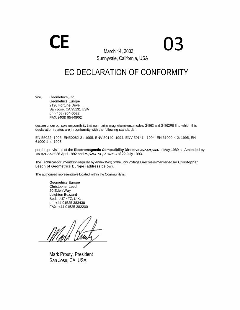
Carefully remove all instrument pieces and lay on a flat surface for assembly (Figure 2). A list of
all the required assembly pieces can be found in Table 1 below.
G-862RBS Manual Operators Manual
Page 8 of 81
Figure 2: Assembly pieces
Table 1: Parts list for G-862RBS
Part Number Name Description
27921-32 G-862 Sensor with cable Main instrument sensor with electronics boards attached
by 3 foot long cable
56145-01 Base Station Data Logger Dogcatcher Data logger console to record data on USB
thumb drive
24810-59 AC/DC 24V Supply Power box to supply the instrument with an outlet plug
20-650-239 USB Thumb Drive 2 ea 1GB Industrial USB thumb drives
65631-01 Tallysman TW5310 Tallysman TW5310 non-magnetic GPS with power
supply and 1PPS interface.
65602-03 Carrying case Heavy plastic carrying/shipping case
65544-02 Padded instrument bag Padded green tote bag to protect sensor through transit
16708-16 Base Station Tripod Kit 5 ea aluminum staff sections, sensor holder and pyramid
staff section
27611-33 G-860 Power/Data cable Power and communications between the magnetometer
and the data logger.
25379-03 Battery Jumper Cable Cable to allow instrument to be powered from 12VDC
battery
27922-OM Operation Manual This document
26648-01 MagMap2000 PC
Software Used to open and manipulate base station data
G-862RBS Manual Operators Manual
Page 9 of 81
Attaching Sensor Bottle
The sensor bottle attaches to one of the three tripod legs which removes the electronics and
magnetic materials used in the sensor bottle far enough away from the magnetic sensor that they
will not interfere with the base station readings. When attaching the bottle assembly to the leg of
the tripod stand make sure that the sensor cable is pointed up so that you have more cable for a
greater distance between the sensor and electronics.
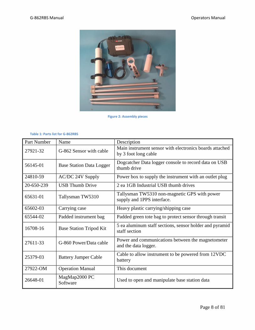
Attach the sensor bottle to the leg by first removing the rubber crutch tip on one of the leg pieces.
3 Remove crutch tip on base station tripod leg to attach the sensor electronics bottle and data storage box
Loosen the knobs on the two black plastic bottle clamps to allow the aluminum rod to slide
through the smaller hole more easily. Slide the aluminum rod into the hole and tighten the knobs
to secure the sensor bottle in place.

G-862RBS Manual Operators Manual
Page 10 of 81
4 Diagram of sensor electronics bottle clamp. The staff section fits through the small hole and is clamped tight
by the two black knobs.
It might be necessary to alternate tightening each knob since tightening one sensor bottle clamp
will cause a looser fit at the other knob. Ensure that the electronics bottle is not able to swing
around freely. This instrument is sensitive enough that it could detect the motion of the
electronics, and contaminate the base station readings. When the electronics bottle is secured
place the rubber crutch tip back on the staff section. Slide the end with the black knob through
one of the bottom three slits on the base station tripod kit and tighten the staff section in place.

G-862RBS Manual Operators Manual
Page 11 of 81
5 Attaching the tripod leg to the base station tripod kit.
Attaching Data Storage Box
To attach the data storage box to the staff section, first completely loosen the latch on the back of
the box by unscrewing the two bolt locks. Place the rubber jackets around the staff section and
align them with the two latches. Close and tighten the latches by screwing the two bolts back
down.
Again you may need to alternate tightening each knob for a firm connection so the box is not
able to move freely. When the box is secured place the rubber crutch tip back on the staff
section. Slide the end with the black knob through one of the bottom three slits on the base
station tripod kit and tighten the staff section in place.

G-862RBS Manual Operators Manual
Page 12 of 81
6 Attaching the data storage box to a second base station leg piece.
Attach the remaining staff section with the crutch tip attached to the last bottom slit of the base
station tripod kit and tighten the staff section in place.
Sensor Clamp
The sensor clamp is designed to allow the operator to adjust the vertical location of the sensor on
the base station to sufficiently remove it from the influences of the GPS above and the
electronics and battery below. Loosen the knob on the sensor clamp to allow the aluminum staff
section to fit through the hole.

G-862RBS Manual Operators Manual
Page 13 of 81
7 Sensor clamp. A) Clamps to secure the sensor in place. B) Rotates the sensor for different orientations. C)
Fixes the sensor clamp assembly on the base station tripod.
Sensor Orientation
The particular installation requirements for each system component must be met in order to
obtain the best performance from the system. It is important to remember that the sensor driver
circuit receives a signal from the sensor whose amplitude is normally one milli-volt as it delivers
both heater and lamp oscillator power to the sensor. Anything that increases the cross-talk
between the power and signal circuits or introduces noise into the power circuit can degrade the
sensor output signal and affect system performance. A Bendix connector terminated multi-
conductor cable is used to supply power to, and data connections to, the matching connector on
the G-862 sensor driver module.

G-862RBS Manual Operators Manual
Page 14 of 81
Magnetic fields are vector fields. At any point they are defined by their magnitude and direction.
If the G-862 sensor is going to accurately measure the local magnetic field magnitude, it must be
properly oriented relative to the local magnetic field direction.
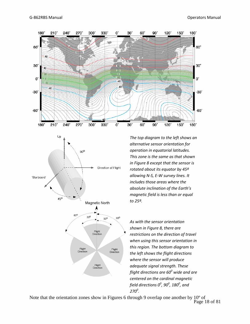
Figure 8: Epoch 2000, 2 degree contour interval
Epoch 2000, 2º contour interval.

G-862RBS Manual Operators Manual
Page 15 of 81
The sensor head must be oriented so that the local field impinges at an angle of from 30º to 60º to
the cylindrical axis of the sensor, for all platform attitudes. Alignments that produce a field/axis
angle less than 15º place the magnetic field within the sensor’s “polar dead zone". Similarly,
alignments that produce a field/axis angle greater than 75º place the magnetic field within the
sensor’s “equatorial dead zone". The sensor will not produce usable data when the angle between
the earth's field and the cylindrical axis falls within one of these two zones.
Unless the sensor is quite near very magnetic objects, the local magnetic field will be almost
entirely due to the earth’s magnetic field. So, in latitudes where the inclination of the earth's field
vector is 45º, vertical orientation of the sensor’s axis will allow operation in all practical flight
attitudes. In equatorial regions it may be necessary to orient the sensor horizontally and at an
angle to the flight path. In Polar Regions the sensor may be mounted with its major axis tilted
east or west to obtain the desired angle.
Figure 9: Magnetic field intensity at the Earth’s surface.
Figure 10: Epoch 2000, 1000 nT contour interval
Epoch 2000, 1000 nT contour interval.

G-862RBS Manual Operators Manual
Page 16 of 81
The maps in Figures 4 and 5 may be used to determine the inclination and total intensity of the
Earth's magnetic field in the intended area of survey. This inclination information should be used
to adjust the sensor orientation for the best performance in the survey area. The intensity
information may be used as a check of the system operation.
In regards to sensor orientation, the Earth’s surface can be divided into three zones based upon
magnetic field inclination: mid-latitude, equatorial, and polar. Within each of these zones there is
a particular sensor orientation that will yield adequate signal strength over the entire zone. These
regions and the corresponding sensor orientations recommended for each region are shown in
Figures 6 through 9.

G-862RBS Manual Operators Manual
Page 17 of 81
The diagram to the left shows the
recommended sensor orientation for
operation in mid-latitudes. This zone is
shown as the shaded regions above
and includes those areas where the
absolute inclination of the Earth’s
magnetic field is greater or equal to
20º and less than or equal to 75º.
There are no restrictions on the
direction of travel when using this
sensor orientation.
The diagram to the left shows the
recommended sensor orientation for
operation in polar latitudes. This zone is
shown as the shaded regions above and
includes those areas where the absolute
inclination of the Earth’s magnetic field is
greater or equal to 65º. There are no
restrictions on the direction of travel when
using this sensor orientation.
G-862RBS Manual Operators Manual
Page 18 of 81
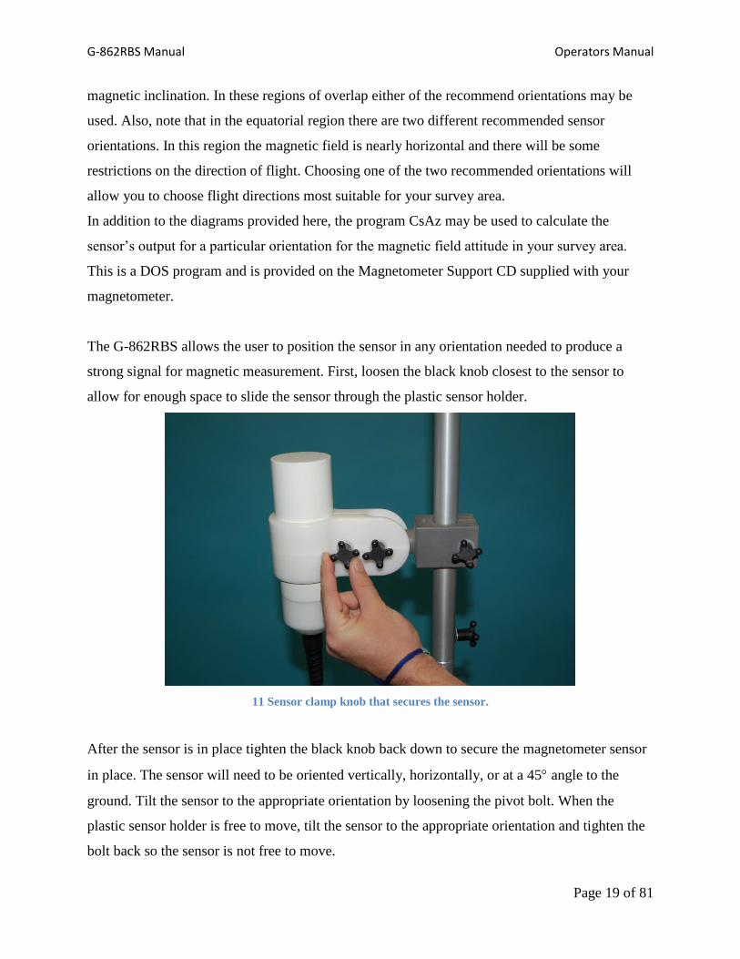
The top diagram to the left shows an
alternative sensor orientation for
operation in equatorial latitudes.
This zone is the same as that shown
in Figure 8 except that the sensor is
rotated about its equator by 45º
allowing N-S, E-W survey lines. It
includes those areas where the
absolute inclination of the Earth’s
magnetic field is less than or equal
to 25º.
As with the sensor orientation
shown in Figure 8, there are
restrictions on the direction of travel
when using this sensor orientation in
this region. The bottom diagram to
the left shows the flight directions
where the sensor will produce
adequate signal strength. These
flight directions are 600 wide and are
centered on the cardinal magnetic
field directions 00, 900, 1800, and
2700.
Note that the orientation zones show in Figures 6 through 9 overlap one another by 10º of
G-862RBS Manual Operators Manual
Page 19 of 81
magnetic inclination. In these regions of overlap either of the recommend orientations may be
used. Also, note that in the equatorial region there are two different recommended sensor
orientations. In this region the magnetic field is nearly horizontal and there will be some
restrictions on the direction of flight. Choosing one of the two recommended orientations will
allow you to choose flight directions most suitable for your survey area.
In addition to the diagrams provided here, the program CsAz may be used to calculate the
sensor’s output for a particular orientation for the magnetic field attitude in your survey area.
This is a DOS program and is provided on the Magnetometer Support CD supplied with your
magnetometer.
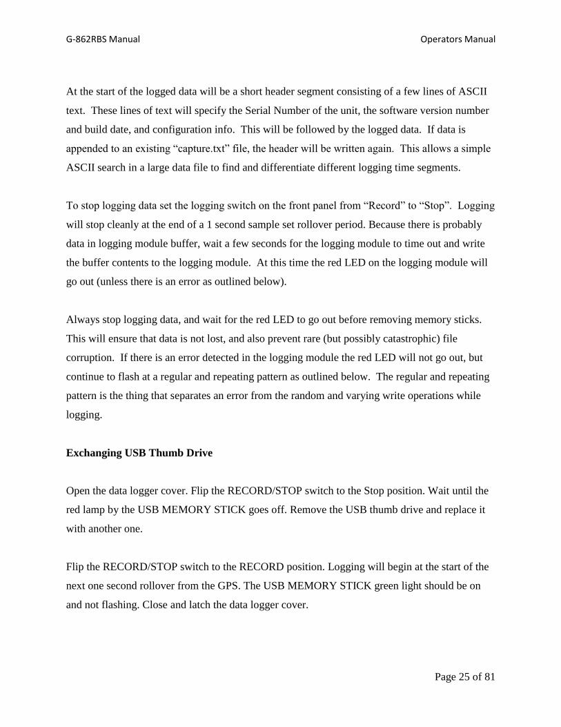
The G-862RBS allows the user to position the sensor in any orientation needed to produce a
strong signal for magnetic measurement. First, loosen the black knob closest to the sensor to
allow for enough space to slide the sensor through the plastic sensor holder.
11 Sensor clamp knob that secures the sensor.
After the sensor is in place tighten the black knob back down to secure the magnetometer sensor
in place. The sensor will need to be oriented vertically, horizontally, or at a 45 angle to the
ground. Tilt the sensor to the appropriate orientation by loosening the pivot bolt. When the
plastic sensor holder is free to move, tilt the sensor to the appropriate orientation and tighten the
bolt back so the sensor is not free to move.

G-862RBS Manual Operators Manual
Page 20 of 81
If you need to rotate the sensor, simply completely unscrew the pivot bolt and rotate the sensor
holder to the appropriate position. Line up the holes of the sensor holder with the holes on the
grey attachment piece and screw the pivot bolt back down until the sensor is not free to rotate.
Once the sensor is in the correct position attach the GPS piece on top of the base station staff
sections by sliding the black knob through the slit and tightening down so it is fixed in place. It is
advised to wrap the GPS cable around the aluminum staff so the cable is not able to move
around, and for a cleaner looking instrument.
Cable Connections
Each cable has a different connector which limits the ability of someone connecting an
instrument into the wrong port. Looking down on the connectors, from left to right, is the port for
the cesium magnetometer electronics bottle, the GPS cable, and then the battery.
Each port connection has a locking ring with keys to make sure the connector is in the right
orientation. The connector will not be allowed to insert if the keys are not correctly aligned.
12 Data Logger box with connectors facing up. The connections, from left to right, are the magnetometer
sensor cable, GPS cable and battery cable.

G-862RBS Manual Operators Manual
Page 21 of 81
This is to ensure that the pins are not bent or damaged. If a pin is bent or snapped, the instrument
will need to be returned to Geometrics for repair. When the keys are aligned, rotate the locking
ring to make a firm connection. Forcing the connector into the port could result in a bent or
snapped pin.
13 GPS cable connector. The keys around the inside must be lined up with the cable connector on the data
storage box. Use the outer locking ring to make the connection.
Once the magnetometer, GPS and battery are connected, turn the power on the box to the on
position. This is done by first pulling the switch out and then moving it to the on position. The
green light next to the switch will turn on if the battery is charged and properly connected.

G-862RBS Manual Operators Manual
Page 22 of 81
14 Power switch is located on the upper left hand side of the front panel. Open the cover and flip the switch
up to turn on the box. The light to the left of the power switch will glow green when correct polarity power is
applied, or will glow red if reverse polarity power is applied.

G-862RBS Manual Operators Manual
Page 23 of 81
Chapter 3: G-862RBS Operation
The G-862RBS has two toggle switches, several LED status lights, a USB port, and a RS 232
port on its front panel.
Turning on the System
Open the data logger cover. Make sure the Record/Stop switch in the USB MEMORY STICK
section is in the STOP position. Insert a USB Thumb Drive into the USB port. Then turn on the
system by flipping the POWER switch towards ON.
Wait for the GPS to find satellites and for the magnetometer to warm up. This should take no
more than 15 minutes in cold weather and could be as short as 5 minutes when the magnetometer
is at room temperature or warmer.
When the system is ready to record, the PROCESSOR STATUS lights should have the following
conditions.
The Processor Status Lights on the Front Panel:
Blue LED:
This Status LED presently does not indicate anything. It may be used for something in the
future.
Yellow LED: The GPS Status Indicator:
1) One flash: Indicates that recognizable GPS serial data characters are being received (i.e.
serial data is recognized and valid carriage returns and line feed are seen). In other words
the baud rate is correct. But no 1PPS pulse is being received.
2) Two flashes: Indicates that 1PPS pulses are being received, but no recognizable GPS serial
data is being received (in other words the baud rate is probably not correct).
3) Three flashes: Indicates that both the GPS serial stream and the 1PPS pulse are being
received, but the GPS stream is not outputting valid location and/or time info. This

G-862RBS Manual Operators Manual
Page 24 of 81
indicates a GPS reception problem, or insufficient time has elapsed to allow the GPS to
lock onto its position.
4) LED on solid: GPS data is reporting valid location/time info and the 1PPS pulse is being
received. The GPS is working correctly.
Green LED: The Mag Data Monitor:
This LED shows that mag data is being received, and flashes at the mag output data rate (10
hertz).
White LED: Phase Lock Indicator:
This LED, when lit, indicates that the magnetometer is being triggered precisely synced to
the GPS 1PPS pulse. This means that the time stamps on the magnetometer data can be
treated with confidence as long as we occasionally get good GPS time info from the
$GPRMC string. The 1PPS tells us the edge of each second transition, but only the GPS
serial data stream tells us which second (of many) that particular one is.
Logging Data with the Dogcatcher logging Module:
Insert a memory stock into the Dog Catcher memory stick slot. The green LED on the logging
module will go from flashing to solid on. This indicates that the memory stick is recognized and
ready to record data.
To log data to Dog Catcher logging module turn the logging switch on the front panel from the
“Stop” position to the “Record” position. Logging to the Dog Catcher will commence at the start
of the next one second rollover (where GPS data is transmitted followed by 10 magnetometer
readings). This allows the recorded data to always start cleanly at the beginning of a 1 second
sample set, as compared to starting in the middle of a sample. As data is written to the memory
stick the red LED on the Dog Catcher logging module will flash on and off. The data is buffered
inside the logging module into 64 byte packets, and is then written in chunks to the memory
stick. The red LED is lit while the writing is taking place.
The data is logged to a file named “capture.txt”. If this file is already present on the memory
stick then all incoming data will be appended to the existing file.
G-862RBS Manual Operators Manual
Page 25 of 81
At the start of the logged data will be a short header segment consisting of a few lines of ASCII
text. These lines of text will specify the Serial Number of the unit, the software version number
and build date, and configuration info. This will be followed by the logged data. If data is
appended to an existing “capture.txt” file, the header will be written again. This allows a simple
ASCII search in a large data file to find and differentiate different logging time segments.
To stop logging data set the logging switch on the front panel from “Record” to “Stop”. Logging
will stop cleanly at the end of a 1 second sample set rollover period. Because there is probably
data in logging module buffer, wait a few seconds for the logging module to time out and write
the buffer contents to the logging module. At this time the red LED on the logging module will
go out (unless there is an error as outlined below).
Always stop logging data, and wait for the red LED to go out before removing memory sticks.
This will ensure that data is not lost, and also prevent rare (but possibly catastrophic) file
corruption. If there is an error detected in the logging module the red LED will not go out, but
continue to flash at a regular and repeating pattern as outlined below. The regular and repeating
pattern is the thing that separates an error from the random and varying write operations while
logging.
Exchanging USB Thumb Drive
Open the data logger cover. Flip the RECORD/STOP switch to the Stop position. Wait until the
red lamp by the USB MEMORY STICK goes off. Remove the USB thumb drive and replace it
with another one.
Flip the RECORD/STOP switch to the RECORD position. Logging will begin at the start of the
next one second rollover from the GPS. The USB MEMORY STICK green light should be on
and not flashing. Close and latch the data logger cover.
G-862RBS Manual Operators Manual
Page 26 of 81
Turning off the System
Flip the RECORD/STOP switch to the STOP position. Wait until the red light in the USB
MEMORY STICK section goes out before removing the USB thumb drive or turning off power.
The Dogcatcher Logging Module Error Status Lights:
If the Dog Catcher logging module detects an error it will set a red LED flash pattern which will
be displayed after the logging has stopped. This flashing pattern will be regular and repeating as
compared to the random and varying flash pattern as data is being logged and written to the
memory stick. These are the error codes:
Rapidly Blinking Data: Data has been received and buffered inside the logging module,
but memory stick is recognized. Data will continue to be buffered until a memory stick is
inserted. If the 13K byte buffer overflows, the oldest data is discarded in favor of new
data.
One Blink and a Pause: Buffer has been overrun. This could happen if something is
wrong with the flash drive, or the flash drive is badly fragmented. Try starting off with a
blank flash drive.
Two Blinks and a Pause: The memory stick is full.
Three Blinks and a Pause: The memory stick, or the “capture.txt” file is set to ‘read
only’.
Five Blinks and a Pause: Communications error: If a byte is received with a framing
error this error gets set. Check the data. If it is only one byte then it isn’t so serious. If it
is every byte then the baud rate to the logging module nay not be right. Lots of data
errors indicate a hardware problem.

G-862RBS Manual Operators Manual
Page 27 of 81
Seven Blinks and a Pause: Hardware within the logging module: Try cycling the
power. If the problem persists the logging module will have to be replaced.
The Logged Data Format:
Standard Format:
This is an example of the standard format of the logged data (minus the header information
which is described below):
$GPRMC,015738.000,A,3724.00107,N,12153.35969,W,0.0,0.0,110314,0.0,W*66
$ 30530.813,0068,01:57:39.055,03/11/14,00
$ 30530.634,0071,01:57:39.155,03/11/14,00
$ 30530.690,0071,01:57:39.255,03/11/14,00
$ 30530.925,0068,01:57:39.355,03/11/14,00
$ 30530.772,0071,01:57:39.455,03/11/14,00
$ 30530.787,0071,01:57:39.555,03/11/14,00
$ 30530.689,0068,01:57:39.655,03/11/14,00
$ 30530.607,0071,01:57:39.755,03/11/14,00
$ 30530.773,0071,01:57:39.855,03/11/14,00
$ 30530.578,0068,01:57:39.955,03/11/14,00
$GPRMC,015739.000,A,3724.00107,N,12153.35969,W,0.0,0.0,110314,0.0,W*67
$ 30530.744,0071,01:57:40.055,03/11/14,00
$ 30530.703,0071,01:57:40.155,03/11/14,00
$ 30530.635,0068,01:57:40.255,03/11/14,00
$ 30530.621,0071,01:57:40.355,03/11/14,00
$ 30530.413,0071,01:57:40.455,03/11/14,00
$ 30530.676,0071,01:57:40.555,03/11/14,00
$ 30530.772,0071,01:57:40.655,03/11/14,00
$ 30530.662,0071,01:57:40.755,03/11/14,00
$ 30530.483,0071,01:57:40.855,03/11/14,00
$ 30530.358,0071,01:57:40.955,03/11/14,00
$GPRMC,015740.000,A,3724.00107,N,12153.35969,W,0.0,0.0,110314,0.0,W*69

G-862RBS Manual Operators Manual
Page 28 of 81
The data sentence begins with the GPRMC message from the GPS. The parts of the GPRMC
message are as follows:
$GPRMC,015738.000,A,3724.00107,N,12153.35969,W,0.0,0.0,110314,0.0,W*66
015738.000 Time of fix 22:54:46 UTC
A Navigation receiver warning A = OK, V = warning
3724.00107,N Latitude 37 deg. 24.00107 min North
12153.35969,W Longitude 121 deg. 53.35969 min West
0.0 Speed over ground, Knots
0.0 Course Made Good, True
110314 Date of fix 11 March 2014
0.0, W Magnetic variation 0.0 West
*68 Mandatory checksum
The magnetometer sentence is as follows:
$ 30530.813,0068,0112,1904,01:57:39.055,03/11/14,00
30530.813 Magnetic Field Reading
0068 Signal Level
01:57:39.155 UTC Time
03/11/14 Date in US Format
00 Status Byte
Magnetometer Only Data Format:
$ 30530.744,0071,01:57:40.055,03/11/14,00
$ 30530.703,0071,01:57:40.155,03/11/14,00
$ 30530.635,0068,01:57:40.255,03/11/14,00
$ 30530.621,0071,01:57:40.355,03/11/14,00
$ 30530.413,0071,01:57:40.455,03/11/14,00
$ 30530.676,0071,01:57:40.555,03/11/14,00
$ 30530.772,0071,01:57:40.655,03/11/14,00
$ 30530.662,0071,01:57:40.755,03/11/14,00
G-862RBS Manual Operators Manual
Page 29 of 81
$ 30530.483,0071,0112,1904,01:57:40.855,03/11/14,00
$ 30530.358,0071,0112,1902,01:57:40.955,03/11/14,00
The Status Byte:
Each magnetometer sample in the output data stream includes the contents of the status
byte. The status byte is an 8 bit number and is output as a two character hexadecimal number.
Currently only the upper 4 bits of the 8 bit number are being used.
The same information in the status byte is also encodes into a flash sequence for the front panel
Status LEDs.
If there are no errors the status byte will be “00”. Anything other than that indicates and error.
There may be more than one error. Each bit of the 8 bit number has a meaning that is defined
below:
80 [hex] or 10000000 [binary]:
This bit is set whenever the G-862 RBS CPU board does not receive a recognizable serial
data stream from the GPS within a 1 second time frame. “Recognizable” means it received a
carriage return and line feed. This error could indicate that there is no GPS data arriving at
the G-862 RBS GPS serial port, or it could indicate that the GPS baud rate and the G-862
serial port baud rate are not set to the same value. In the absence of GPS data, the G-862
RBS will make up a GPS RMC string as a token place holder. All the data fields within this
made up string will be nulls.
40 [hex] or 01000000 [binary]:
This bit is set whenever the GPS data does not contain a valid fix and is therefore suspect.
This can be due to not enough satellites, no clear view of the sky, GPS hasn’t acquired the
satellites yet, no GPS serial data being received (which would also set the 0x80 bit), or a
defective GPS.
G-862RBS Manual Operators Manual
Page 30 of 81
20 [hex] or 00100000 [binary]:
This bit is set whenever the 1 PPS pulse is not received. This could be due to a GPS
reception problem, the GPS hasn’t acquired the satellites yet, or a defective GPS.
10 [hex] or 00010000 [binary]:
This bit is set whenever the 1 PPS phase locked loop has not closed. It means that the
magnetometer trigger is not phase locked to the 1 PPS pulse. This will always be the case
upon power up. Once the 1 PPS pulses start to arrive from the GPS, it takes about 15-20
seconds for the phase locked loop to synchronize with the 1PPS pulses. At that time this bit
will be cleared.
If more than one error is occurring then the individual bits will add in a hexadecimal fashion.
For example, if no GPS serial data stream is received both the 80 [hex] and the 40 [hex] bits will
be set. The status byte in the log file would be the sum of those two, or C0 [hex].
The Logging Header:
Each data logging is started a block of header information is written such as follows:
# Software Version: 01.00.00
# Build Date: Mar 10 2014 15:22:00
# Output Baud Rate = 19200
# Mag Baud Rate = 19200
# GPS Baud Rate = 19200
# Debug Port Baud Rate = 19200
# 1 PPS Edge = positive edge
# Auto 1 PPS Edge Detect = true
# Log GPS Data with Mag Data = true
Each line of the header block is described below:

G-862RBS Manual Operators Manual
Page 31 of 81
# Software Version: 01.00.00
This is the G-862 RBS CPU software version number.
# Build Date: Mar 10 2014 15:22:00
This is the time and date that the software was compiled and loaded into the G-862 RBS
CPU board.
# Output Baud Rate = 19200
This is the serial output port baud rate from the Arduino CPU. It feeds the Monitor port,
the Bluetooth port, and the Dogcatcher Logger port.
# Mag Baud Rate = 19200
This is the baud rate of the Arduino serial port that is connected with the magnetometer.
# GPS Baud Rate = 19200
This is the baud rate of the Arduino serial port that is connected with the GPS.
# Debug Port Baud Rate = 19200
This is the baud rate of the Arduino serial port that is connected to the Arduino USB
connector. This serial to USB port is used to download and debug the software via the
development software running on a Windows PC.
# 1 PPS Edge = positive edge
This defines which edge of the 1 PPS pulse is being used for the one second rollover. It
is either “positive edge” or “negative edge”. If “Auto 1 PPS Edge Detect” = true, this is
the edge that the Auto detect routine chose after analyzing the 1 PPS waveform. If the
“Auto 1 PPS Edge Detect” = false, this was set directly by firmware.
# Auto 1 PPS Edge Detect = true
When true, the 1PPS rollover edge is selected by analyzing the 1 PPS waveform on start
up. It works by assuming that a positive edge 1 PPS pulse will have a duty cycle that is

G-862RBS Manual Operators Manual
Page 32 of 81
mostly low, with a with a relatively narrow positive pulse at the 1 PPS time. In contrast,
a negative edge 1 PPS waveform will have a duty cycle that is mostly high, with a
relatively narrow negative going pulse at the 1 PPS time.
# Log GPS Data with Mag Data = true
If true then both magnetometer and GPS data are logged together. If false, only the
magnetometer data is logged (along with GPS functionality and health info in the Status
Byte).
GPS/Magnetometer Timing:
It is not necessary to understand this section to use the G-862 RBS. If you accept the time
stamps on the data in the logged data file as being absolutely correct then you do not need to read
further into this section. But if you study the format of the logged data questions may arise, like:
“Why is the GPS data at time hh:mm:22 seconds appear after the magnetometer data time
stamped at hh:mm:23.xxx seconds? Shouldn’t data in a logged file be time sequential?”
Or
“Why is the magnetometer data have funny time stamps such as hh:mm:23.155 seconds? Why
not even 100 mS time stamp values?”
Or
“What does the time stamp signify? ”
The timing of the data synchronization and collection is a little tricky. The following diagram
and description will hopefully make it clearer:

G-862RBS Manual Operators Manual
Page 33 of 81
Figure 15: GPS and Magnetometer Timing Diagram

G-862RBS Manual Operators Manual
Page 34 of 81
Everything is synchronized to the 1PPS leading edge. The 1PPS pulse is used to generate a
phase locked 10 hertz signal to externally trigger the magnetometer such that its cycling is also
phase locked to the 1PPS pulse. The 1PPS pulse from the GPS precisely defines that a 1 second
rollover has happened, but which second that happens to be is not transmitted for many hundreds
of milliseconds later. Worse, the exact timing of that transmitted time information varies from
sample to sample, with the number of satellites, and with location. In the previous timing
diagram note the 1PPS pulse on the top waveform. The 1PPS critical time in this case is on
positive going edge of the pulse. The left side of the diagram is arbitrarily defined as second [T
= 0]. The second waveform from the top shows the outline of the serial transmission from the
GPS to the G-862 (and to the Arduino CPU serial port 2). Inside this data packet is the exact
time of the 1PPS edge that happened a few hundred milliseconds ago. Because the timing of this
serial data is not defined and highly variable, and because we want to have a regular defined
output format, the GPS data is buffered inside the G-862 Arduino CPU and is always output
between the last magnetometer sample (of a batch of ten) and the first sample of the next batch
of ten. Thus the GPS data gets recorded later about one second behind the magnetometer data
which is time stamped ahead of the delayed GPS.
The magnetometer is triggered by sending a “$” trigger command via the serial port. There is
more detail on this in the “Block Diagram Section” section. This trigger waveform is seen in the
third waveform down in the diagram below. This trigger is generated by the Arduino CPU on
serial port 1from a software phase locked loop driven by the 1PPS edge. Both the 1PPS PLL and
the 10 hertz trigger routines are interrupt driven. To keep the timing as accurate as possible we
make the interrupts happen at different times so they can never be simultaneous. The time offset
in this case is 5 mS. Thus the timing of the magnetometer trigger for sample one and (of a batch
of ten) [T=0], happens at [T=0.005] seconds. The end of magnetometer sample one happens
when the next trigger to start sample two arrives at [T=0.105] seconds. The magnetometer value
for sample one is the average of the magnetic field from [T=0.005] seconds to [T=0.105]. The
average of that time span is [T=0.055] seconds. Sample two would be [T=0.155] seconds,
sample three would be [T=0.255] seconds and so on. The time stamp reflects the exact center of
each magnetometer cycle period. This is why the time stamps for the magnetometer data appear
in the data file as they do.
G-862RBS Manual Operators Manual
Page 35 of 81
Even though the time stamp information in the data file is logged with a 1 mS resolution, the
actual accuracy of that time stamp is much better at about 10 µS. Thus a time stamp of
23:10:45.055 seconds in the log is more like 23:10:45.05500 seconds accuracy.
As mentioned above the delayed GPS data is always inserted between magnetometer sample ten
(of the previous batch of ten), and the first sample of the next batch of ten. The data for
magnetometer sample one is calculated after the sample period is over and sample two has been
started. At this time the GPS data is written out to the logger/monitor/Bluetooth serial port
following directly be the data for magnetometer sample one. In waveforms 4 and 5 on the timing
diagram you can see the transmitted magnetometer data going into the Arduino CPU serial port 1
(the GPS data comes in on serial port 2) and the combined data (GPS and magnetometer) goes
out on serial port 3 – and on to the data logger/monitor ports Because the GPS and
Magnetometer data are all buffered on the Arduino CPU, if the magnetometer data has to be
delayed by a bit to allow the GPS data to insert itself beforehand it won’t cause a problem.
You may also note that the GPS transmission time going out the Arduino CPU is much shorter
than the time it took coming into the Arduino CPU. In this particular example, the input baud
rate on serial port 2 is 4800 baud, while the outgoing baud rate is 19200 baud. This may or may
not be the case in a particular G-862 RBS system – the GPS, Magnetometer, and output baud
rates are configurable. All that is required is that the Arduino CPU baud rates match the baud
rates of the devices feed them. This is covered in more detail in the “G-862 RBS Commands Via
the Monitor Port” in Appendix 1.
Block Diagram:
The CPU:
The heart of the G-862 RBS data logger is the Arduino Mega 2560 CPU board. It contains a
RISC based 32 bit microprocessor running at 16 Megahertz. The CPU has four independent
serial ports. The first serial port (#0) is used for downloading the software from the
development system running on a PC (via a USB port). It also allow for software debugging.
Serial port 1 is used to trigger and receive data from the magnetometer. Serial port #2 is used
G-862RBS Manual Operators Manual
Page 36 of 81
to send commands to and receive data from the GPS. Serial port #3 is used to output the
synchronized and combined GPS and mag data to the Data Monitor connector on the front
panel, to the Bluetooth port, and to the Dog Catcher data logging module (if logging is
enabled via the logging on/off switch). In addition, commands can be sent to the Arduino
CPU, to the GPS, or to the Magnetometer. See the section on “G-862 RBS Commands via
the Monitor Port” in Appendix 1 for more details.
In addition to the four serial ports there are several digital input/output pins. These are used
for various functions such as driving the LEDs, reading the four factory test configuration
jumpers, reading the logging on/off switch position, and sensing the GPS 1 PPS signal.
The serial and digital ports at the Arduino board are buffered on a Geometrics designed
“shield” board which sits between the vulnerable Arduino pins and the outside world. In
addition to buffering and protecting the CPU, the four serial ports are level shifted to make
full plus and minus RS-232 serial data voltage swings.
The 1 PPS Phase Locked Loop:
In order to keep the magnetometer synchronized to the GPS one PPS pulse it must be
externally triggered by a ten hertz clock that is phase locked to the one PPS pulse. This is
done using a software digital phase lock loop in the Arduino microprocessor. The one PPS
pulse comes in through a digital I/O line and interrupts the CPU. The timing of this pulse is
compared to a timer count inside the microprocessor, and that timer period is adjusted
up/down as needed to keep the two in lock step with one another. That same timer is used to
generate the trigger timing to the magnetometer.
In actual fact, the phase locked loop generates a 100 hertz phase locked output. This gets
divided by ten to make the 10 hertz mag cycle rate. The reason for this is that it allows for
better resolution for controlling the PLL timer and increases the phase accuracy of the PLL.
In addition it should be noted that the 100 hertz phase locked timer is offset from the 1 PPS
edge by a constant 5 milliseconds (half of the 10 millisecond period of 100 hertz). The
reason for this is that both the 1 PPS detect and 100 hertz timer rollover routines are interrupt
G-862RBS Manual Operators Manual
Page 37 of 81
driven. By having them offset it guarantees that they can never happen on top of one
another. This removes any timing variation caused by one interrupt happening before or
after the other. This 5 mS offset can be seen in the time stamped magnetometer data.
When power is first applied the 1 PPS pulse from the GPS and the timer that triggers the
magnetometer are asynchronous. About 15 seconds or so after the G-862 RBS starts
receiving the 1 PPS pulse from the GPS the digital phase locked loop adjusts the timer into
synch with the 1 PPS pulse. When this happens the PLL LED on the front panel is lit up
solid indicating that the two are phase locked. This phase locked status is also reflected in
the status byte which is logged with the mag data.
The phase lock loop keeps the mag triggered in synch with the 1 PPS pulse to a within +/- 5
microseconds. The time stamp in the data is only printed out to a 1 millisecond resolution,
but you could safely add another couple zeroes to the time stamp after the one mS digit.
Magnetometer Trigger:
Geometrics’ cesium magnetometers are designed such that they can be wired together such
that you get one data stream with the mag data concatenated one after the other. Thus if you
wired three magnetometers together this way you would get a serial data stream with data
from magnetometer 1, a comma delimiter, followed by magnetometer 2 data, a comma, and
then magnetometer 3 data. In this mode the magnetometers are wired such that the serial
output of the first is connected to the serial command input of the second, and so on. The
serial output for the last magnetometer in the chain will contain all the magnetometers data
concatenated together. When a “$” character is received by a magnetometer in the chain it
knows it is receiving magnetometer data. The incoming “$” character is passed through to
the next magnetometer immediately (and so on down the chain), while the rest of the
incoming magnetometer data follows thereafter. When the current magnetometer sees the
incoming carriage return / line feed it strips it off and replaces it with a comma, then appends
its own magnetometer data behind it (adding a carriage return / line feed at the end.
The Arduino uses this concatenation feature of Geometrics cesium magnetometers to
externally trigger (and synchronize) the magnetometer to the 1PPS pulse of the GPS. At
G-862RBS Manual Operators Manual
Page 38 of 81
trigger time, the Arduino CPU sends a “$” out serial port #1 triggering the magnetometer.
The magnetometer has actually already been triggered by its own internal free running cycle
time counter. What the “$” trigger actually does is cram into the cycle time counter what the
timer count should be based on a cycle time that began one serial character transmission time
ago. Remember is takes a fixed (and predictable) amount of time to transmit the “$”
character at the current baud rate, and this method of cramming in the proper count
compensates for this character transmission time and keeps the mag trigger phase locked to
the trigger time – not when the “$” character is received. This “$” character is followed by a
carriage return and line feed sent from the Arduino to the magnetometer.
The “$” and carriage line feed gets converted by the magnetometer as though it is previous
magnetometer data in a chain of magnetometers. Thus the “$” gets passed through, and the
carriage return / line feed is stripped and replaced with a comma. Then the magnetometer
appends its own data and sends it out the magnetometer serial port back to serial port #1 on
the Arduino board. Thus the Arduino CPU board receives from the magnetometer a data
string like:
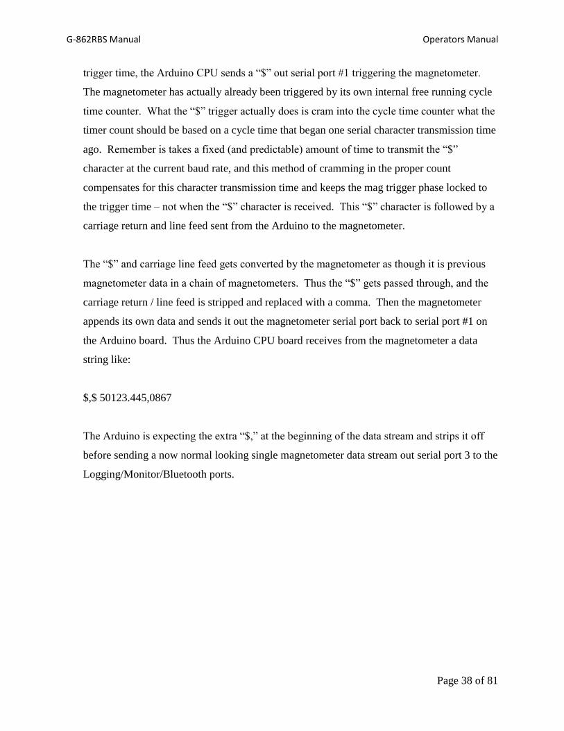
$,$ 50123.445,0867
The Arduino is expecting the extra “$,” at the beginning of the data stream and strips it off
before sending a now normal looking single magnetometer data stream out serial port 3 to the
Logging/Monitor/Bluetooth ports.

G-862RBS Manual Operators Manual
Page 39 of 81
Chapter 4: MagMonitor Smartphone App
Geometrics has designed and implemented an installable application for Android smartphones
and tablets to monitor the data streams as they are being recorded in the Dogcatcher data logger.
This allows the operator to have a visual representation of the data at a safe distance from the
base station so the base station data is not contaminated. This application is found on
Geometrics’ website and can be uploaded to your Android device through USB connection,
email or internet download. This application is not found in the Android marketplace.
Installation
The installation process of the MagMonitor App is very simple through two methods: direct
download from E-mail or file transfer over the micro-USB cable. Before transferring or
downloading the file make sure that your Android device allows applications that do not appear
on the Google Market to be installed. This is not a default feature of the Android tablets or
smartphones, so to do this you must go to Settings and then select Applications. In this screen
there will be a check box or setting to allow installation of non-Market applications. Make sure
that this is checked or turned on, or else you will not be able to install and run the MagMonitor
application.
On your Android device, open the E-mail with the attached application file, format is .APK.
Select the attachment for download and a security screen will appear to make sure you want to
install this program. Select yes and the application will be installed. Go to your applications and
select MagMonitor to start the application.
USB transfer
Connect your Android device to the computer through the micro-USB cable. When the device is
found select the option to mount the device as a Disk Drive on the “Connect to PC” screen. This

G-862RBS Manual Operators Manual
Page 40 of 81
will allow you to transfer the MagMonitor Application file onto your Android device. Open a
Windows explorer window and navigate to the Disk Drive associated with the Android device.
Select yes and the application will be installed. Go to your applications and select MagMonitor
to start the application. Upon start-up the application will see if the Bluetooth is turned on, and if
not will ask you if you want to turn the Bluetooth on. Once the Bluetooth is turned on select the
Menu button (the triple bar) and select Connect. You can now “Scan for Devices” to find the
Bluetooth transmitter from the G-862RBS. Once the G-862RBS is found select this Bluetooth
device to pair the base station with your Android device and ready to use.
Bluetooth connection
The Bluetooth provided by Geometrics has a working range of about 10 meters. Stand a
reasonable distance away from the base station such that the presence of the phone or tablet is
not detected in the magnetic data but can still communicate with the Bluetooth transmitter. Each
device has different magnetic signatures so it is good practice to first determine the magnetic
cleanliness of the Android device prior to surveying. This is done by slowly moving the Android
device to see if there is a magnetic response from the magnetometer. If there is, move farther
away before you start recording.
Upon start-up the application will see if the Bluetooth is turned on, and if not will ask you if you
want to turn the Bluetooth on.

G-862RBS Manual Operators Manual
Page 41 of 81
Figure 16: Initial screen to indicate Bluetooth usage
Once the Bluetooth is turned on select the Menu button (the triple bar) and select Connect. You can
now “Scan for Devices” to find the Bluetooth transmitter from the G-862RBS.

G-862RBS Manual Operators Manual
Page 42 of 81
Figure 17: Scan for devices page
Once the G-862RBS is found select this Bluetooth device to pair the base station with your
Android device and ready to use.
Magnetometer Trace
The first screen shown when the MagMonitor Application is running is the Magnetometer Trace window
that shows an analog trace of the magnetometer data, see Figure 17.

G-862RBS Manual Operators Manual
Page 43 of 81
Figure 18: Magnetometer Trace Screen
A multiple line header displays a digital output of the magnetometer data readings as well as signal level.
The signal level is a gauge of the quality of the magnetic readings, with values lower than 500 being
questionable. This is a good check that the instrument is working properly and that the sensor is not
operating in a dead zone. At initial start up the signal level will be in the first decades, but after the sensor
has warmed up the readings should range from 600-2000, eventually stabilizing at a near constant
number.
GPS Latitude/ Longitude
The second line shows the GPS Latitude and Longitude readings in decimal form. These fields use
positive or negative numbers to show the correct hemisphere you are working in. In Figure 18 it shows a
positive number for the Latitude which corresponds to the Northern Hemisphere, and a negative
Longitude which corresponds to the Western Hemisphere.

G-862RBS Manual Operators Manual
Page 44 of 81
Date and Time
The date is displayed in the mm/dd/yy format standard in the United States. This is currently the
only date format available, but future versions of this program will allow for the European
convention of dd/mm/yy.
Time is displayed in UTC time, the standard for GPS units. The time format is hh:mm:ss.(ms). It
is important to note what the difference between the local time and UTC time for downloading
the data. This is discussed in greater detail in the following chapter.
Scale
The scale bar for the analog trace is shown in the bottom left-hand corner of the screen. You can
increase and decrease the scale by selecting the Enlarge and Reduce buttons at the bottom of the
screen.
GPS Track Plot
The GPS track plot screen is shown in Figure 19. This screen was added as a way to visually show the
accuracy of the GPS. This screen also helps show if the GPS loses satellites such that it cannot generate a
3-D fix. This will be shown by a drastic change in the GPS location accuracy on the track plot. Select the
enlarge or reduce button to zoom in or out on the track plot to see the overall accuracy of the instrument.
The red dot is the location of the latest GPS message received, with the black and grey dots representing
past locations.

G-862RBS Manual Operators Manual
Page 45 of 81
Figure 19: GPS track plot
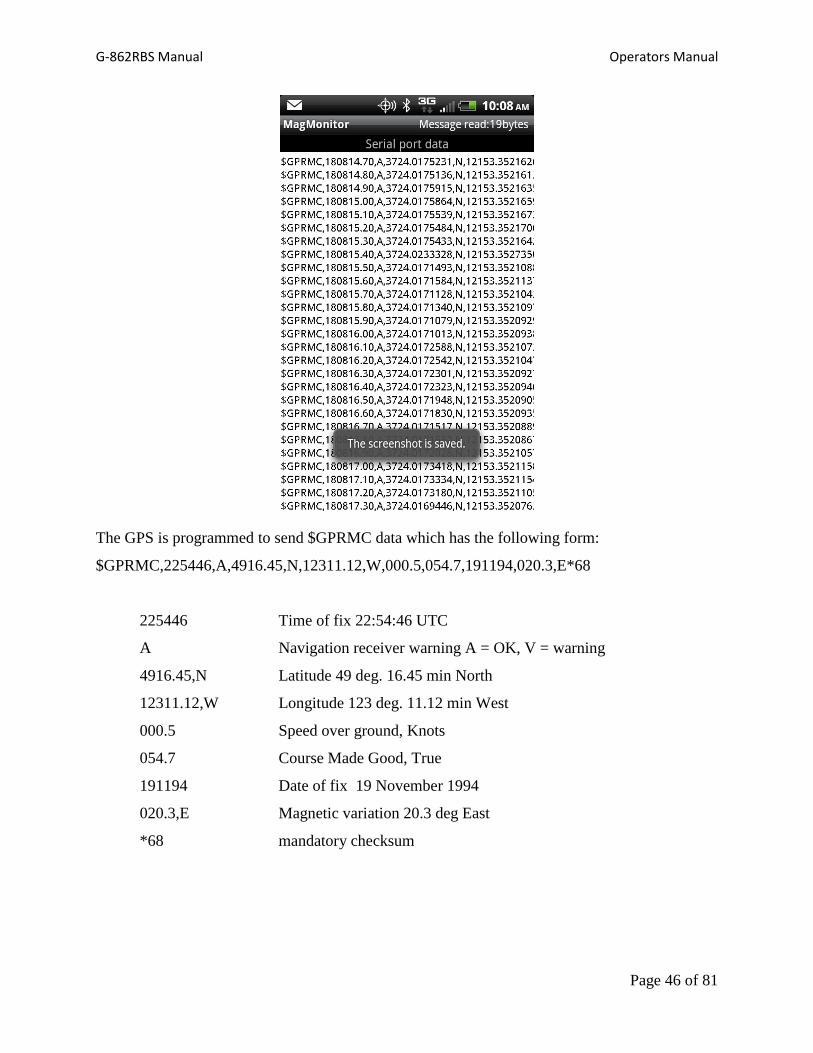
GPS Serial Data Screen
The GPS data screen is a terminal emulation screen that shows the full GPS messages as they are
logged by the DogCatcher.
G-862RBS Manual Operators Manual
Page 46 of 81
The GPS is programmed to send $GPRMC data which has the following form:
$GPRMC,225446,A,4916.45,N,12311.12,W,000.5,054.7,191194,020.3,E*68
225446 Time of fix 22:54:46 UTC
A Navigation receiver warning A = OK, V = warning
4916.45,N Latitude 49 deg. 16.45 min North
12311.12,W Longitude 123 deg. 11.12 min West
000.5 Speed over ground, Knots
054.7 Course Made Good, True
191194 Date of fix 19 November 1994
020.3,E Magnetic variation 20.3 deg East
*68 mandatory checksum
G-862RBS Manual Operators Manual
Page 47 of 81
Currently the entire string might not fit on the screen depending on the orientation and screen
size. Further efforts are being made to adjust for the screen size so that the entire string can be
examined for quality control purposes.
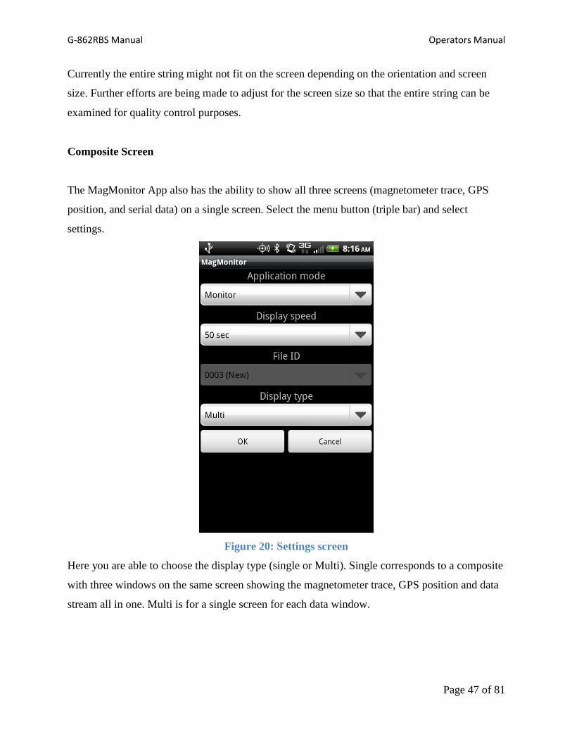
Composite Screen
The MagMonitor App also has the ability to show all three screens (magnetometer trace, GPS
position, and serial data) on a single screen. Select the menu button (triple bar) and select
settings.
Figure 20: Settings screen
Here you are able to choose the display type (single or Multi). Single corresponds to a composite
with three windows on the same screen showing the magnetometer trace, GPS position and data
stream all in one. Multi is for a single screen for each data window.

G-862RBS Manual Operators Manual
Page 48 of 81
Figure 21: Selection between Single or Multi screen types
An example of the Single screen is shown below:
G-862RBS Manual Operators Manual
Page 49 of 81
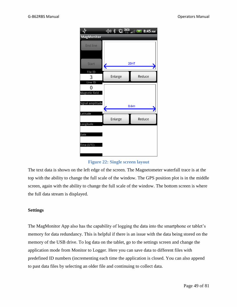
Figure 22: Single screen layout
The text data is shown on the left edge of the screen. The Magnetometer waterfall trace is at the
top with the ability to change the full scale of the window. The GPS position plot is in the middle
screen, again with the ability to change the full scale of the window. The bottom screen is where
the full data stream is displayed.
Settings
The MagMonitor App also has the capability of logging the data into the smartphone or tablet’s
memory for data redundancy. This is helpful if there is an issue with the data being stored on the
memory of the USB drive. To log data on the tablet, go to the settings screen and change the
application mode from Monitor to Logger. Here you can save data to different files with
predefined ID numbers (incrementing each time the application is closed. You can also append
to past data files by selecting an older file and continuing to collect data.

G-862RBS Manual Operators Manual
Page 50 of 81
Display speed dictates how quickly the magnetometer waterfall trace goes down its window. A
50 s display speed means that 50 seconds worth of data will be displayed on the screen.

G-862RBS Manual Operators Manual
Page 51 of 81
Chapter 5: Data Download
Uploading G-862RBS into MagMap2000
To use the data recorded by the G-862RBS to diurnally correct the magnetic readings of a mobile
magnetometer system the files must be reconfigured to the necessary time stamp form for the
MagMap2000 software to properly read the information.
MagMap2000 software provides RBS data download interface consistent with G-856 / G-858 /
G-859 data download. The difference is that in case of RBS data is simply copied from the RBS
USB stick onto host computer, and new file name is assigned based on UTC data of RBS data
set.
To download RBS data make sure that RBS data stick is plugged in the available USB port and
recognized by the PC, and press “Import” button from MagMap2000 tool bar.
Program display import dialog with RBS data selection at the bottom:
Select “RBS data” from dialog above.
Alternatively user can select “File / Import RBS data” from the main menu.
G-862RBS Manual Operators Manual
Page 52 of 81
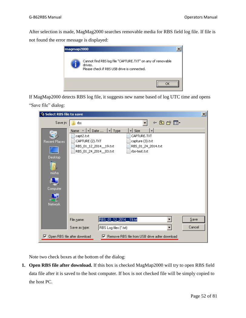
After selection is made, MagMag2000 searches removable media for RBS field log file. If file is
not found the error message is displayed:
If MagMap2000 detects RBS log file, it suggests new name based of log UTC time and opens
“Save file” dialog:
Note two check boxes at the bottom of the dialog:
1. Open RBS file after download. If this box is checked MagMap2000 will try to open RBS field
data file after it is saved to the host computer. If box is not checked file will be simply copied to
the host PC.

G-862RBS Manual Operators Manual
Page 53 of 81
2. Remove RBS file from USB drive after download. If this box is checked MagMag2000
removes RBS field file from the USB drive after it is copied into PC, to free space for new data.
Additional confirmation dialog is displayed before file is actually removed.
After user presses “Save” button MagMap2000 copies field from USB stick to host PC under
selected name, opens it if requested and removes from USB storage. The next section explains in
detail how the RBS file is loaded.
To read already saved RBS files use “File / Open” dialog as explained below.
Read RBS data into MagMap2000.
Geometrics Remote Base Station data is presented with file with extension .txt. The file holds
mixture of raw GPS messages, such as RMC and magnetometer readings, accurately time
stamped with the UTC time using GPS serial and PPS (pulse per second) output. Thus data is
already has UTC time stamp. The typical example of RBS data is presented below:
$ 42204.989,1277,03:07:16.955,01/16/14,00
$GPRMC,030716,A,3724.0098,N,12153.3513,W,000.0,000.0,160114,013.7,E*62
$ 42205.009,1277,03:07:17.055,01/16/14,00
$ 42204.947,1274,03:07:17.155,01/16/14,00
$ 42205.028,1277,03:07:17.255,01/16/14,00
$ 42204.894,1274,03:07:17.355,01/16/14,00
$ 42204.894,1274,03:07:17.455,01/16/14,00
$ 42205.161,1274,03:07:17.555,01/16/14,00
$ 42204.932,1277,03:07:17.655,01/16/14,00
$ 42204.627,1274,03:07:17.755,01/16/14,00
$ 42204.970,1277,03:07:17.855,01/16/14,00
$ 42204.928,1277,03:07:17.955,01/16/14,00
$GPRMC,030717,A,3724.0098,N,12153.3514,W,000.0,000.0,160114,013.7,E*64
$ 42204.970,1277,03:07:18.055,01/16/14,00
The magnetometer readings start with “$” and consist of total magnetic field, signal strength,
UTC time and date, and hexadecimal status flag. All fields are comma separated. The status flag
is zero if no errors were detected.
RBS file can be treated as Base Station data; in this case GPS raw messages are not used, and
MagMap2000 opens one standard base station data. Data can be also treated as rover; in this

G-862RBS Manual Operators Manual
Page 54 of 81
case MagMap2000 parses raw GPS messages to extract positions. In latter case it opens two
windows: readings view and GPS view, similar to data loaded as SURFER or airborne
magnetometer. Please do not close any of these windows while working on the data.
MagMap2000 does not allow opening of multiple RBS or GPS data in rover mode, but data from
another RBS file from stationary magnetometer could be open as base station.
Note that RBS data is complementary in case of Base Station mode. Other rover data such as
airborne, marine or land should be loaded before or after RBS base data is loaded.
RBS rover mode is self-sufficient, assuming RBS was moved to perform magnetometer survey.
In this case data can be exported into SURFER or Geosoft formats for further processing.
To open RBS file select File / Open from MagMap2000 main menu and select filter settings as
Remote Base Station (RBS) data as it is shown on the picture below, and select file to open.

G-862RBS Manual Operators Manual
Page 55 of 81
Program starts reading RBS file as shown below:
After reading is completed, RBS status dialog is displayed:

G-862RBS Manual Operators Manual
Page 56 of 81
The following controls are available:
1. How to use RBS data. Possible selections are “Use as Base Station” or “Use as Rover
(GPS+data)” In first case program opens base station window, in second case two windows
(similar to airborne or SURFER data) with magnetometer readings and positions.
2. Adjust RBS time stamps to the time zone: RBS data always recorded in UTC time. Therefore
it could be desirable to adjust then to the local time zone. Checking this box enables time zone
selection below. In case of rover mode both magnetometer and GPS positions times are adjusted
to local time zone.
3. RBS flags. Reports number of readings with specific flags set. These indicate problems with
RBS and/or GPS. For the normal operation all flags should be 0.
4. Correct RBS errors automatically. This check box is enabled only if some of the RBS flags is
not zero. Program will try to restore missing time stamps in this case.
After the “Ok” button is clicked program creates one or two windows, depending on the mode
selection.
G-862RBS Manual Operators Manual
Page 57 of 81
Appendix 1: G-862RBS Configuration
The G-862RBS is made up from a Geometrics G-862 magnetometer, a Tallysman TW5310 GPS
receiver, a Dogcatcher USB thumb drive recorder in a weatherproof enclosure with power
supplies and Bluetooth transmitter, a non-magnetic tripod, and cable set.
In operation data from the GPS is used to trigger the magnetometer, which is synchronized to the
GPS 1PPS output. The GPS is configured to transmit NMEA $GPRMC messages at 1 Hz. This
GPS message setting was chosen because it contains the date with the time stamping. The system
Baud rate is set to 19,200. Each magnetometer sample is time stamped with GPS UTC date and
time.
Data Collection Set Up
After the G-862RBS is completely assembled and power is running connect the data logger
DATA Monitor port to your computer using an RS-232 extension cable. You may need to use
the USB-RS232 adapter provided by Geometrics to successfully connect to your computer.
You can download the most recent version of Tera Term for the operating system you are using
here:
http://logmett.com/
After installing Tera Term you can run the executable file and a command window appears:

G-862RBS Manual Operators Manual
Page 58 of 81
Figure 23: Serial connection screen in Tera Term
The data logger DATA Monitor port connects and streams the data to the computer through an
RS-232 serial port. So we must select the radio button Serial at the bottom of the window.
Figure 24: Serial Port Setup

G-862RBS Manual Operators Manual
Page 59 of 81
Upon initial startup Tera Term will assume a baud rate of 9600. However, each piece of
equipment in the G-862RBS is preset at the factory to send out data at 19,200 baud. With the
computer and the data box operating at different baud rates you will see random characters
populating the screen, which can be seen in the background of Figure 22. To change the baud
rate go to Setup/Serial Port… and the window shown above will appear. Choose the 19,200 baud
rate in the list in the drop down menu. The other options should remain the same, with Data at 8
bit, Parity at none, Stop is 1 bit and Flow control is none. Make sure that the correct COM port is
selected and then click OK.
G-862RBS Commands Via the Front Panel Monitor Port:
The G-862 can be configured into many different operating modes by sending commands to it
using a terminal emulation program via the Monitor port on the front panel. The commands fall
into three groups. There are commands that configure the Arduino CPU, commands that get
routed through to configure the GPS, and commands that get routed through to the
Magnetometer.
Note that these commands are used to set up the G-862 RBS, GPS, and Magnetometer, but once
the system is set up and the configuration saved you probably never need to use these
commands. If you bring in a different GPS, or swap to another magnetometer then these
commands will be useful to get the new components set up.
All the commands are sent by typing them into a terminal emulation program which in turn sends
those typed characters into the Monitor port on the G-862. Each command string is followed by
pressing the <enter> key. Note that all commands are lower case letters, and there are no spaces.
Arduino Commands:
Most of the commands are used to set up the Arduino CPU board. They all have the command
preamble of “*ard:” signifying that the command will be received and acted on by the Arduino
CPU itself. Below is a list of those commands and their functions:

G-862RBS Manual Operators Manual
Page 60 of 81
*ard:saveconfig
This command takes the current setup and store it to EEPROM (non-volatile memory) so that the
G-862 RBS will record this configuration on power up.
*ard:loadconfig
This command will reload the configuration from EEPROM. This allows you to undo any
changes made to the configuration since the last power up (assuming you have not saved them).
The same thing could be accomplished by cycling the power, but this command allows the
configuration to be restored without powering down the GPS and magnetometer.
*ard:gpsbaud=4800
*ard:gpsbaud=9600
*ard:gpsbaud=19200
*ard:gpsbaud=38400
*ard:gpsbaud=57600
*ard:gpsbaud=115200
These commands set the baud rate of the GPS serial port on the Arduino CPU board. The
Arduino board baud rate must match the GPS baud rate. The baud rates denoted in the above
command list are all the possible baud rates for the Arduino GPS serial port.
*ard:magbaud=19200
Currently 19200 is the only baud rate available for the magnetometer. It is the fastest baud rate
that the magnetometer can output. In future releases of the software we will be adding a
command to be able to set the Arduino magnetometer serial port to 9600 baud.
*ard:loggps=true
*ard:loggps=false

G-862RBS Manual Operators Manual
Page 61 of 81
When loggps=true the output data stream has both magnetometer and GPS data combined
together. When false the GPS data is stripped off and just magnetometer data is logged.
However the functionality and health of the GPS data is reflected in the status byte at the end of
every magnetometer sample.
*ard:gpsdirect
This invokes a special operation mode that forms a direct pathway between the GPS and a
computer through the G-862 RBS console. Once invoked the only way to exit this mode is by
powering down and then powering back up.
In this mode every character that is sent by the computer to the monitor port on the G-862 RBS
is echoed directly to the GPS. Every character sent out the GPS is echoed through to the monitor
port (and on to the computer). Some GPS units are not configured via command line instructions
– but rather use graphical user interface programs to set them up (like the Tallysman). This
mode allows the GUI configuration program to set up the GPS as though the computer was
directly wired into the GPS serial port.
Even though all characters out of the computer and/or out of the GPS are echoed on through,
keep in mind that inside the G-862 RBS they are entirely separate serial ports and may be
running at different baud rates. Any baud rate translation is done by the Arduino as required.
In the gpsdirect mode everything other than the special data pathway works normally. The
interrupt routines still function, the magnetometer gets triggered, etc.
See Appendix 2 on “Configuring the GPS via the Monitor Port of the G=862RBS” for an
example on configuring a Tallysman GPS using this mode.
*ard:magdirect
This mode is identical to the gpsdirect mode above except it opens a direct pathway to the
magnetometer instead of the GPS. This is a handy way to configure the magnetometer directly.
G-862RBS Manual Operators Manual
Page 62 of 81
In this mode, all characters entered at the computer are echoed directly to the magnetometer, and
all character sent by the magnetometer are sent out the Monitor port and on to the computer.
For a list of the magnetometer commands please refer to the G-862 magnetometer manual.
There is one non-obvious caveat when sending commands directly to the magnetometer. The
method used to trigger the magnetometer puts it from master mode into slave mode and changes
its magnetometer number from “0” to “1”. Usually when setting up a single magnetometer there
is no need to specify the magnetometer number in the magnetometer commands since it assumes
it is magnetometer zero when a number isn’t specified. But in this case the all commands must
be entered with a magnetometer number of “01” added. For example, to turn on the
magnetometer signal level channel you need the command “A1001” instead of “A10” or
“A1000”. This is covered in detail in the G-862 magnetometer manual.
Once entered the only way out of the magdirect mode is to power down, then power back up.

G-862RBS Manual Operators Manual
Page 63 of 81
Appendix 2: GPS and Magnetometer Programming
Overview
The G-862RBS is designed to simultaneously acquire GPS positions while it is acquiring
magnetic data. The Tallysman TW5310 GPS is preset at the Geometrics factory to send the
$GPRMC position and time string in order to provide automatic date and time stamps. The G-
862RBS uses the integrated GPS data to produce a highly accurate and precise time stamp which
will be able to synchronize the data of both the base station and a mobile magnetometer for more
accurate diurnal corrections.
All communication with the GPS takes place through the RS-232 extension on the data cable
provided.
Collecting GPS Data
The G-862RBS is equipped with either a Tallysman TW5310 GPS mounted on the top of the
base station assembly. These GPS units are cabled to the G-862RBS data logging box. All
necessary wiring connections are in the power cable supplied with the battery box. The GPS is
pre-configured by Geometrics to provide the $GPRMC NMEA sentence only at 1 Hz, and to
output 1PPS timing pulse.
There is no need to program the Tallysman TW5310 GPS unless the GPS memory has become
corrupted and it has lost its programming. If that were to occur it could start sending improper
GPS serial data. If so, we recommend the following procedure:

G-862RBS Manual Operators Manual
Page 64 of 81
Tallysman TW5310 GPS Setup
Required Equipment:
1. Windows XP - 8 PC with RS 232 Serial port
2. Tera Term or HyperTerminal software
3. Tallysman TW5X10Configurator.exe software installed on the Windows computer
4. P/N 60-230-237 RS 232 Extension Cable
Procedure:
1. Open the data logger cover and turn off the G-862RBS power switch.
2. Connect the 60-230-237 cable between the G-862RBS datalogger DATA Monitor
RS-232 connector on the front panel, and a serial port on the computer.
3. Turn on the G-862RBS power switch
4. Start the Tera Term or HyperTerminal software.
5. Set communications to 8 data bits, No parity, 1 stop bit, and 19,200 baud.
The Tallysman GPS uses a special Windows configuration program called
“TW5X10Configurator.exe” to setup the GPS. In order to use this program the Windows
computer has to interface directly to the GPS via a serial port. In the normal operating mode the
GPS get combined with magnetometer data and sent to the logger. To allow the configuration
mode to work we must first invoke a special mode in the G-862 which forms a direct path
between the computer and the GPS. To invoke this special mode we start up a terminal
emulation program such as TeraTerm and monitor the serial output from the G-862. If logging is
enabled turn it off. Then type the following command to the G-862 using TeraTerm:
*ard:gpsdirect
Followed by the <enter> key. Note that the characters are all lower case and there are no spaces
in the command (see the section on G-862 Commands for details on all the possible commands
that can be sent to the G-862 RBS).
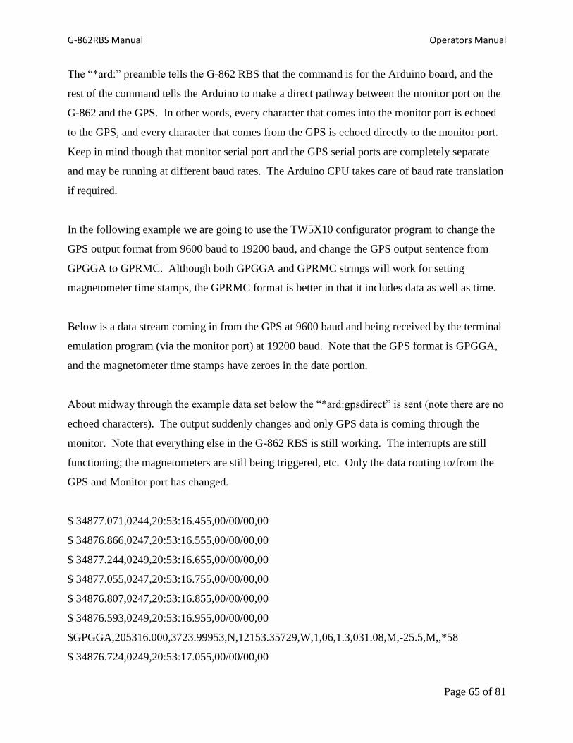
G-862RBS Manual Operators Manual
Page 65 of 81
The “*ard:” preamble tells the G-862 RBS that the command is for the Arduino board, and the
rest of the command tells the Arduino to make a direct pathway between the monitor port on the
G-862 and the GPS. In other words, every character that comes into the monitor port is echoed
to the GPS, and every character that comes from the GPS is echoed directly to the monitor port.
Keep in mind though that monitor serial port and the GPS serial ports are completely separate
and may be running at different baud rates. The Arduino CPU takes care of baud rate translation
if required.
In the following example we are going to use the TW5X10 configurator program to change the
GPS output format from 9600 baud to 19200 baud, and change the GPS output sentence from
GPGGA to GPRMC. Although both GPGGA and GPRMC strings will work for setting
magnetometer time stamps, the GPRMC format is better in that it includes data as well as time.
Below is a data stream coming in from the GPS at 9600 baud and being received by the terminal
emulation program (via the monitor port) at 19200 baud. Note that the GPS format is GPGGA,
and the magnetometer time stamps have zeroes in the date portion.
About midway through the example data set below the “*ard:gpsdirect” is sent (note there are no
echoed characters). The output suddenly changes and only GPS data is coming through the
monitor. Note that everything else in the G-862 RBS is still working. The interrupts are still
functioning; the magnetometers are still being triggered, etc. Only the data routing to/from the
GPS and Monitor port has changed.
$ 34877.071,0244,20:53:16.455,00/00/00,00
$ 34876.866,0247,20:53:16.555,00/00/00,00
$ 34877.244,0249,20:53:16.655,00/00/00,00
$ 34877.055,0247,20:53:16.755,00/00/00,00
$ 34876.807,0247,20:53:16.855,00/00/00,00
$ 34876.593,0249,20:53:16.955,00/00/00,00
$GPGGA,205316.000,3723.99953,N,12153.35729,W,1,06,1.3,031.08,M,-25.5,M,,*58
$ 34876.724,0249,20:53:17.055,00/00/00,00
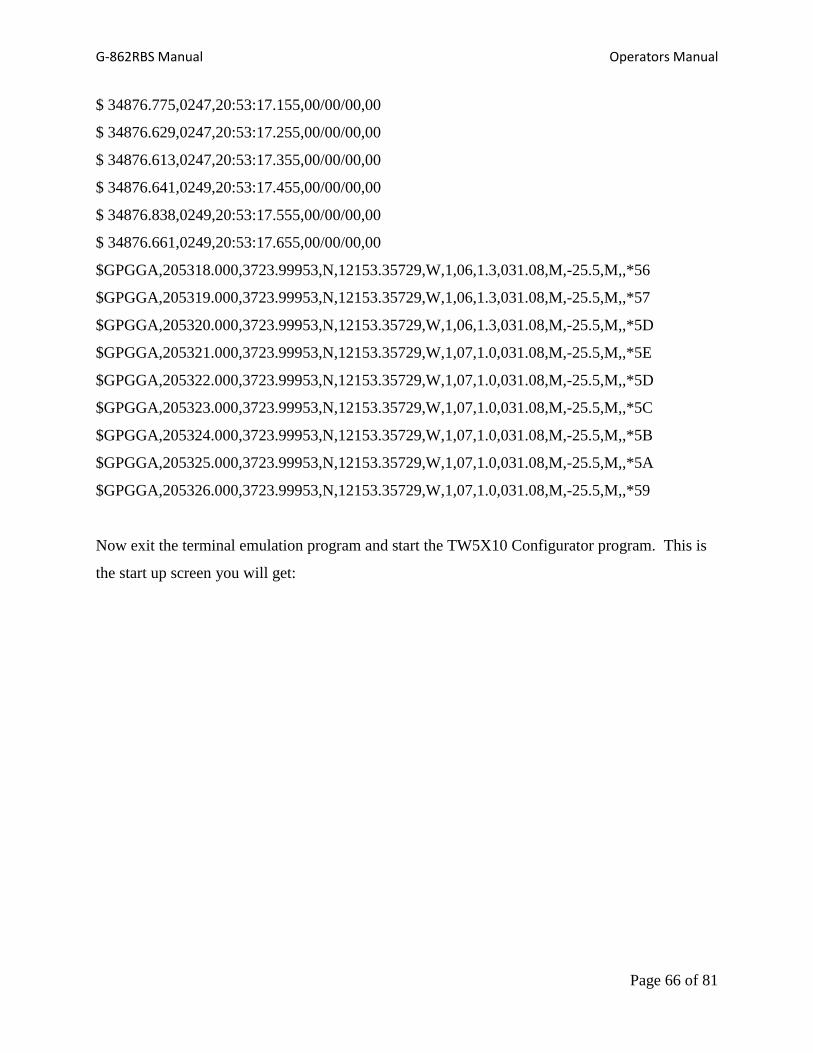
G-862RBS Manual Operators Manual
Page 66 of 81
$ 34876.775,0247,20:53:17.155,00/00/00,00
$ 34876.629,0247,20:53:17.255,00/00/00,00
$ 34876.613,0247,20:53:17.355,00/00/00,00
$ 34876.641,0249,20:53:17.455,00/00/00,00
$ 34876.838,0249,20:53:17.555,00/00/00,00
$ 34876.661,0249,20:53:17.655,00/00/00,00
$GPGGA,205318.000,3723.99953,N,12153.35729,W,1,06,1.3,031.08,M,-25.5,M,,*56
$GPGGA,205319.000,3723.99953,N,12153.35729,W,1,06,1.3,031.08,M,-25.5,M,,*57
$GPGGA,205320.000,3723.99953,N,12153.35729,W,1,06,1.3,031.08,M,-25.5,M,,*5D
$GPGGA,205321.000,3723.99953,N,12153.35729,W,1,07,1.0,031.08,M,-25.5,M,,*5E
$GPGGA,205322.000,3723.99953,N,12153.35729,W,1,07,1.0,031.08,M,-25.5,M,,*5D
$GPGGA,205323.000,3723.99953,N,12153.35729,W,1,07,1.0,031.08,M,-25.5,M,,*5C
$GPGGA,205324.000,3723.99953,N,12153.35729,W,1,07,1.0,031.08,M,-25.5,M,,*5B
$GPGGA,205325.000,3723.99953,N,12153.35729,W,1,07,1.0,031.08,M,-25.5,M,,*5A
$GPGGA,205326.000,3723.99953,N,12153.35729,W,1,07,1.0,031.08,M,-25.5,M,,*59
Now exit the terminal emulation program and start the TW5X10 Configurator program. This is
the start up screen you will get:
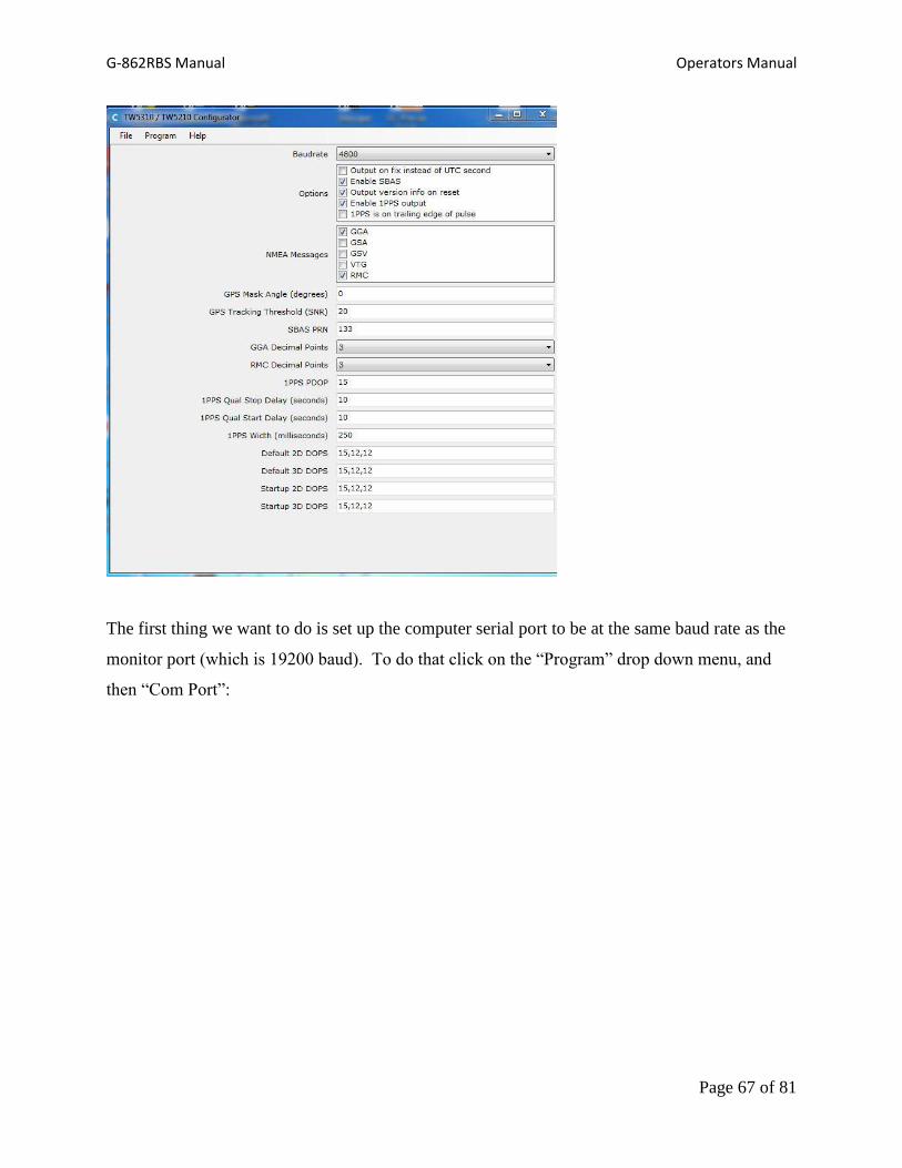
G-862RBS Manual Operators Manual
Page 67 of 81
The first thing we want to do is set up the computer serial port to be at the same baud rate as the
monitor port (which is 19200 baud). To do that click on the “Program” drop down menu, and
then “Com Port”:
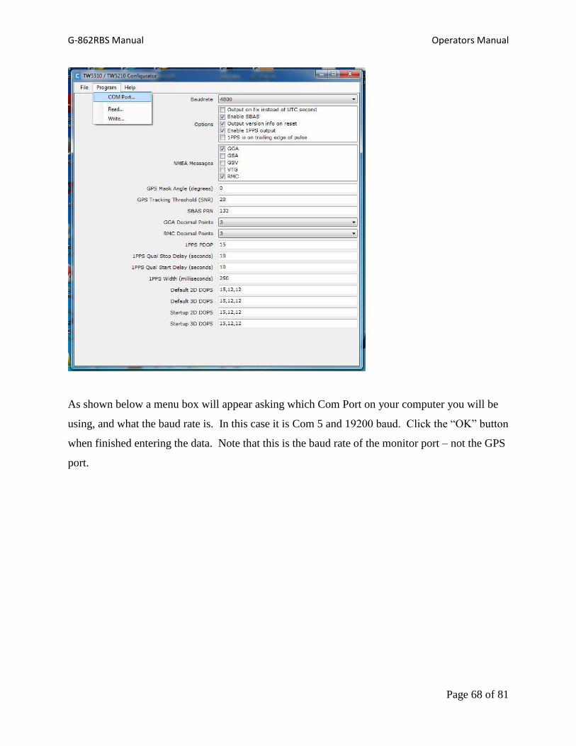
G-862RBS Manual Operators Manual
Page 68 of 81
As shown below a menu box will appear asking which Com Port on your computer you will be
using, and what the baud rate is. In this case it is Com 5 and 19200 baud. Click the “OK” button
when finished entering the data. Note that this is the baud rate of the monitor port – not the GPS
port.

G-862RBS Manual Operators Manual
Page 69 of 81
Then go back to the “Program” drop down menu and click on “Read” as shown below:
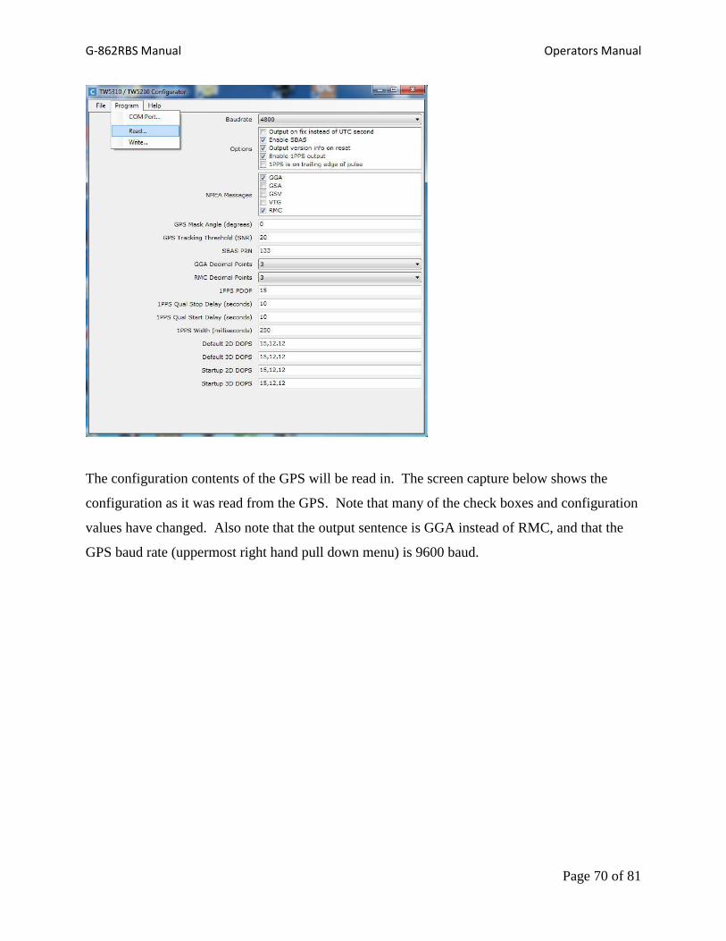
G-862RBS Manual Operators Manual
Page 70 of 81
The configuration contents of the GPS will be read in. The screen capture below shows the
configuration as it was read from the GPS. Note that many of the check boxes and configuration
values have changed. Also note that the output sentence is GGA instead of RMC, and that the
GPS baud rate (uppermost right hand pull down menu) is 9600 baud.

G-862RBS Manual Operators Manual
Page 71 of 81
Now we want to change the GPS baud rate (upper right pull down menu) to 19200 baud, and
change the NMEA message from GGA to RMC. In the screen capture below this has been
performed:
G-862 Magnetometer Setup
Magnetometer cycle rate is fixed at 10 Hz. Magnetometer timing should not be changed, but it is
possible to change magnetometer Baud Rate and enable or disable internal analog channels so
that diagnostic information can be recorded. Enabling internal analog channels will reduce
maximum recording time.
Required Equipment:
1. Windows XP - 8 PC with RS 232 Serial port
2. Tera Term or HyperTerminal software
3. Optional CM201CFG software (installs automatically with MagLog)
G-862RBS Manual Operators Manual
Page 72 of 81
4. P/N 60-230-237 RS 232 Extension Cable
Procedure
1. Open the data logger cover and turn off the G-862RBS power switch.
2. Connect the 60-230-237 cable between the G-862RBS datalogger DATA Monitor
RS-232 connector on the front panel, and a serial port on the computer.
3. Turn on the G-862RBS power switch
4. Start the Tera Term or HyperTerminal software. Then select the appropriate computer
COM port.
5. Set communications to 8 data bits, No parity, 1 stop bit, and 19,200 baud.
6. Type *ard:magdirect to form a direct pathway between the magnetometer and your
computer.
7. When using terminal software set the magnetometer cycle rate, type the command,
C001001, to set the time to 0.1 second (10 Hz). Analog channels 0 through 7 can be enabled by
typing A1x01 followed by the <enter> key (where x is the analog channel number). Analog
channels 0 through 7 can be disabled by typing A0x01 followed by the <enter> key (where x is
the analog channel number). You should always enable analog channel 0, which is
magnetometer sensor signal amplitude. Finally type the command, UPDATE, to store the new
setting as the power on default.

G-862RBS Manual Operators Manual
Page 73 of 81
Appendix 3: CESIUM-VAPOR SENSOR THEORY
Note: The following section is provided for information purposes only. Understanding this
theoretical discussion is not required for proper operation of the magnetometer.
For purposes of this discussion, the ambient magnetic field or earth's magnetic field is called H0.
A separate magnetic field generated by an AC signal applied to a coil inside the sensor is called
H1. This coil is shown cross-section along with the other sensor components in Figure A11.
To initiate operation of the sensor, the lamp oscillator's RF power increases until the lamp strikes
(plasma ignites and fluoresces). The lamp oscillator then reduces its power to produce the
regulated amount of light. The heater warms the absorption cell until a Cesium vapor is formed.
A lens bends the light from the lamp to parallel rays. The lamp produces many spectral lines but
only one line in the infrared region is employed. All of the other light is blocked by a high grade
optical filter.
The infrared line of interest is then passed through a split-circular polarizer. On one side of the
polarizer the transmitted light has an electrostatic vector that advances with a right-handed
rotation. For conceptual purposes, it can be said that all of the photons in this light have the
Figure A11. G-862RBS cesium-vapor
Lamp
Lens
Filter
Polarizer
Photocell
Lens
H1 Coil
Absorption
Cell
G-862RBS Manual Operators Manual
Page 74 of 81
same right-hand spin direction. The light transmitted through the other side of the split-circular
polarizer produces light in which the vector advances with a left-handed rotation, therefore
having the opposite spin. Both circular polarized light beams pass through the absorption cell.
Because there is a buffer gas in the cell, the single cell can be considered as two separate cells,
each having the opposite sense polarized light passed through it. Both light beams exit the cell
and pass to a second lens. This lens focuses the light onto an infrared photo detector.
Because Cesium is an alkali metal, the outer most electron shell (orbit) has only one electron. It
is the presence of this single electron that makes the Cesium atom well-suited for optical
pumping and therefore magnetometry.
The Cesium atom has a net magnetic dipole moment. This net dipole moment, termed F, is the
sum of the nuclear dipole moment, called I, and the electron's angular momentum, called J.
In a Cesium atom:
I = 7/2
J = 1/2
and thus F can have two values depending on whether the electron's angular momentum adds to
or subtracts from the nuclear dipole moment. Therefore, F can have the value of 3 or 4. These
values are called the hyperfine energy levels of the ground state of Cesium.
Normally the net dipole moments are randomly distributed about the direction (vector sum of the
3 axial components) of the ambient magnetic field (H0). Any misalignment between the net
atomic dipole moment and the ambient field vector causes the Cesium atom to be at a higher
energy level than if the vectors were aligned. These small differences are called Zeeman
splitting of the base energy level.
The laws of quantum electrodynamics limit the inhabitable atomic magnetic dipole orientations
and therefore the atomic excitation energy to several discrete levels: 9 levels for the F=4 state

G-862RBS Manual Operators Manual
Page 75 of 81
and 7 levels for the F=3 state. It is this variation in electron energy level state that is measured
to compute the ambient magnetic field strength.
When a photon of the infrared light strikes a Cesium atom in the absorption cell, it may be
captured and drive the atom from its present energy level to a higher energy level. To be
absorbed the photon must not only have the exact energy of the Cesium band gap (therefore the
narrow IR line) but must also have the correct spin orientation for that atom.
There is a high probability that the atom will immediately decay back to the initial energy level
but its original orientation to the ambient field is lost and it assumes a random orientation. An
atom that returns to the base level aligned such that it can absorb another photon, will be driven
back to the higher state. Alternately, if the atom returns to the base level with an orientation that
does not allow it to absorb an incoming photon, then it will remain at that level and in that
orientation. Atoms will be repeatedly driven to the higher state until they happen to fall into the
orientation that cannot absorb a photon. Consequently, the circularly polarized light will
depopulate either the aligned or inverse aligned energy states depending on the orientation (spin)
of light polarization. Remember that one side of the cell is right-hand polarized and the other
left-hand polarized to minimize sensor rotational light shifts and subsequent heading errors.
Once most of the Cesium atoms have absorbed photons and are in a state that does not allow
them to absorb another photon, the light absorption of the cell is greatly reduced, i.e., more light
hits the photo detector. If an oscillating electromagnetic field of the correct radio frequency is
introduced into the cell, the atoms will be driven back (depopulating the energy level) into an
orientation that will allow them to absorb photons again. This frequency is called the Larmor
frequency and is exactly proportional to the energy difference caused by the Zeeman splitting
mentioned previously. This energy splitting is in turn directly proportional to the ambient
magnetic field strength. The relationship between frequency and energy is given by:
E = f
Where:

G-862RBS Manual Operators Manual
Page 76 of 81
E is the Zeeman energy difference
f is the frequency of the Larmor
is Planck's constant
In Cesium this Larmor frequency is exactly 3.49872 times the ambient field measured in nano-
Teslas (gammas). In the G-862RBS this radio frequency field is generated by a coil, called the
H1 coil that is wound around the tube holding the optical components. When the R.F. field is
present the total light passing through the cell is reduced because atoms are in an energy state in
which they can again absorb the infrared light.
There is a small variation in the atomic light absorption at the frequency of the applied H1
depopulation signal. This variation in light intensity appears on the photo-detector as a small AC
signal (micro-volts). If this AC signal is amplified and shifted to the correct phase, it can be fed
back to the H1 coil to produce a self-sustaining oscillation. In practice, simply connecting the
90° phase shifted and amplified signal to the H1 coil will cause the oscillation to spontaneously
start. Reversing the direction of the earth field vector (H0) through the sensor requires the drive
to the H1 coil to be inverted to obtain oscillation.

G-862RBS Manual Operators Manual
Page 77 of 81
Appendix 4: CSAZ
Cesium Sensor Azimuth Program
CSAZ is a program written by Geometrics for users of Cesium magnetometers. The purpose of
the program is to determine the proper orientation of the Cesium sensor at various Earth field dip
angles (field inclination). AZ stands for azimuth or inclination.
The program is located on the MagMap2000 install disk included with the G-862RBS. Once
MagMap2000 is installed, CSAZ will also be installed.
The CSAZ program is available from our FTP site at
ftp://geom.geometrics.com/pub/mag/software
Please read the manual that is included with the program for complete instructions on how to use
the CSAZ program for sensor orientation solutions at various locations on the globe. Note that
you should use the “generic” CSAZ mode for G-862RBS solutions.

G-862RBS Manual Operators Manual
Page 78 of 81
Appendix 5: Instrument Specifications
Magnetometer:
Self-oscillating split-beam Cesium Vapor (non-radioactive)
MAGNETOMETER OPERATING RANGE: 20,000 to 100,000 nT
OPERATING ZONES:
The earth’s field vector should be at an angle greater than 10 from the
sensor’s equator and greater than 10 from the sensor’s long axis.
Automatic hemisphere switching.
SENSITIVITY: < 0.004 nT/Hz rms. Typically 0.02 nT P-P at a 0.1 second sample rate
(90% of all readings falling within the P-P envelope)
ABSOLUTE ACCURACY: < 3 nT throughout range
GPS Receiver Time accuracy; 20ns, RMS, max. data rate; 1 Hz
Data Logger Serial logger, removable USB thumb drive.
Data Format ASCII, MS Windows PC compatible, FAT32 file format.
Capacity
22 days using 1Gbyte USB thumb drive while recording magnetometer at
10 Hz rate with GPS receiver output set to provide GPRMC data sentence
(UTC) at 1 Hz rate. Logger will accept 0.5 to 8 Gbyte USB thumb drive
with FAT32 file format.
Mechanical / Environmental Shipping weight: 12.7kg (28Lbs.)
OPERATING TEMPERATURE: -30 F to +122 F (-35 C to +50 C)
STORAGE TEMPERATURE: -48 F to +158 F (-45 C to +70 C)
ALTITUDE: Up to 30,000 ft (9,000 m)
WEATHERPROOF: O-Ring sealed for operation in the rain and/or 100% humidity
Power: 10 to 36 VDC, 30 Watt. or 110-220VAC (50-60hz)
Standard Accessories: 110-220 VAC (50-60hz) power supply, Flash card reader, shipping/storage
case, Geometrics MagMap2000 data processing and display software.
SPECIFICATIONS SUBJECT TO CHANGE WITHOUT NOTICE