Embed Size (px)
Citation preview

Product Code: L2062
Issue June 2017
GB
Operation Manual and Parts BookWFM-115 and WFM-130 Flail Mowers


CONTENTS
Welcome to your new Wessex Product . . . . . . . . . . . . . . . . . . . . . . . . . . . . . . . . . . . . . . . . .3
Safety Decals . . . . . . . . . . . . . . . . . . . . . . . . . . . . . . . . . . . . . . . . . . . . . . . . . . . . . . . . . . .4, 5
Important Safety Warnings . . . . . . . . . . . . . . . . . . . . . . . . . . . . . . . . . . . . . . . . . . . . . . . . . . .6
Warranty . . . . . . . . . . . . . . . . . . . . . . . . . . . . . . . . . . . . . . . . . . . . . . . . . . . . . . . . . . . . . . . . .7
Main parts description . . . . . . . . . . . . . . . . . . . . . . . . . . . . . . . . . . . . . . . . . . . . . . . . . . . . . .8
Configurations . . . . . . . . . . . . . . . . . . . . . . . . . . . . . . . . . . . . . . . . . . . . . . . . . . . . . . . . . . . . 9
Configurations - Technical Specifications . . . . . . . . . . . . . . . . . . . . . . . . . . . . . . . . . . . . . . .10
Safety / General Safety Instructions . . . . . . . . . . . . . . . . . . . . . . . . . . . . . . . . . . . . . . . . . . .11
Safety / Equipment Safety Instructions . . . . . . . . . . . . . . . . . . . . . . . . . . . . . . . . . . . . . . . . .12
Safety / Operating Safety Instructions . . . . . . . . . . . . . . . . . . . . . . . . . . . . . . . . . . . . . . . . .13
Safety / Transporting Safety Instructions . . . . . . . . . . . . . . . . . . . . . . . . . . . . . . . . . . . .14, 15
Maintenance Safety Instructions . . . . . . . . . . . . . . . . . . . . . . . . . . . . . . . . . . . . . . . . . . . . . .15
Storage Safety Instructions / Safety Labels . . . . . . . . . . . . . . . . . . . . . . . . . . . . . . . . . . . . .16
Set Up / Connecting to the Tractor . . . . . . . . . . . . . . . . . . . . . . . . . . . . . . . . . . . . . . . . . . . .17
Driveline Installation / Driveline Length Check . . . . . . . . . . . . . . . . . . . . . . . . . . . . . . . .18, 19
Tractor Flail Mower Stability . . . . . . . . . . . . . . . . . . . . . . . . . . . . . . . . . . . . . . . . . . . . . . . . .20
Operating / Start-up . . . . . . . . . . . . . . . . . . . . . . . . . . . . . . . . . . . . . . . . . . . . . . . . . . . . .21, 22
Cutting Height Adjustments . . . . . . . . . . . . . . . . . . . . . . . . . . . . . . . . . . . . . . . . . . . . . . .23, 24
Rake Adjustment . . . . . . . . . . . . . . . . . . . . . . . . . . . . . . . . . . . . . . . . . . . . . . . . . . . . . . . . . .25
Side Shift Adjustment . . . . . . . . . . . . . . . . . . . . . . . . . . . . . . . . . . . . . . . . . . . . . . . . . . . . . .26
Belt Tensioning Adjustment . . . . . . . . . . . . . . . . . . . . . . . . . . . . . . . . . . . . . . . . . . . .27, 28, 29
Stopping and Disconnection . . . . . . . . . . . . . . . . . . . . . . . . . . . . . . . . . . . . . . . . . . . . . . . . .30
Transporting / Maintenance . . . . . . . . . . . . . . . . . . . . . . . . . . . . . . . . . . . . . . . . . . . . . . . . . .31
Rotor Tools Replacement . . . . . . . . . . . . . . . . . . . . . . . . . . . . . . . . . . . . . . . . . . . . . . . . . . .32
Maintenance . . . . . . . . . . . . . . . . . . . . . . . . . . . . . . . . . . . . . . . . . . . . . . . . . . . .33, 34, 35, 36
Storage / Scrapping . . . . . . . . . . . . . . . . . . . . . . . . . . . . . . . . . . . . . . . . . . . . . . . . . . . . . . . .37
Troubleshooting . . . . . . . . . . . . . . . . . . . . . . . . . . . . . . . . . . . . . . . . . . . . . . . . . . . . . . . . . . .38

CONTENTS
Torque Values Table / Spare Parts . . . . . . . . . . . . . . . . . . . . . . . . . . . . . . . . . . . . . . . . . . . .39
Parts Illustration - Main Frame and Rotor Assembly . . . . . . . . . . . . . . . . . . . . . . . . . . .40, 42
Parts List - Main Frame and Rotor Assembly . . . . . . . . . . . . . . . . . . . . . . . . . . . . . . . .41, 43
Parts Illustration - Transmission and Skid . . . . . . . . . . . . . . . . . . . . . . . . . . . . . . . . . . . . . . .44
Parts List - Transmission and Skid . . . . . . . . . . . . . . . . . . . . . . . . . . . . . . . . . . . . . . . . . . . .45
Parts Illustration - Gearbox . . . . . . . . . . . . . . . . . . . . . . . . . . . . . . . . . . . . . . . . . . . . . . . . . .46
Parts List - Gearbox . . . . . . . . . . . . . . . . . . . . . . . . . . . . . . . . . . . . . . . . . . . . . . . . . . . . . . .47
Parts Illustration - 3 Point Mast Assembly . . . . . . . . . . . . . . . . . . . . . . . . . . . . . . . . . . .48, 50
Parts List - 3 Point Mast Assembly . . . . . . . . . . . . . . . . . . . . . . . . . . . . . . . . . . . . . . . . .49, 51
Parts Illustration - Shield, Front Plates, Parking Stand . . . . . . . . . . . . . . . . . . . . . . . . . . . . .52
Parts List - Shield, Front Plates, Parking Stand . . . . . . . . . . . . . . . . . . . . . . . . . . . . . . . . . .53
Parts Illustration - Rear Cover . . . . . . . . . . . . . . . . . . . . . . . . . . . . . . . . . . . . . . . . . . . . . . .54
Parts List - Rear Cover . . . . . . . . . . . . . . . . . . . . . . . . . . . . . . . . . . . . . . . . . . . . . . . . . . . .55
Parts Illustration - Rear Roller Assembly . . . . . . . . . . . . . . . . . . . . . . . . . . . . . . . . . . . . . . .56
Parts List - Rear Roller Assembly . . . . . . . . . . . . . . . . . . . . . . . . . . . . . . . . . . . . . . . . . . . . .57
Parts Illustration - Rear Cover with Racks . . . . . . . . . . . . . . . . . . . . . . . . . . . . . . . . . . . . . .58
Parts List - Rear Cover with Racks . . . . . . . . . . . . . . . . . . . . . . . . . . . . . . . . . . . . . . . . . . . .59
P.T.O. Shaft - Operation and Maintenance . . . . . . . . . . . . . . . . . . . . . . . . . . . . . . . . . . .60, 61
Safety Training Induction . . . . . . . . . . . . . . . . . . . . . . . . . . . . . . . . . . . . . . . . . . . . . . . . . . . .62
Daily Inspection Record . . . . . . . . . . . . . . . . . . . . . . . . . . . . . . . . . . . . . . . . . . . . . . . . . . . .63
CE Certificate . . . . . . . . . . . . . . . . . . . . . . . . . . . . . . . . . . . . . . . . . . . . . . . . . . . . . . . . . . . . .6

3
WELCOME TO YOUR NEW WESSEX PRODUCT
Thank you for purchasing a Wessex product. As a Wessex customer, you now number among themost important people of our business and we will endeavour to give you the best service availablethrough our dealer network.
Please read this Manual carefully and familiarise yourself and other persons that will be using themachine with its contents, to ensure the optimum performance and working life of your machine. Itis advisable that a copy of this Manual is kept in the workshop and one copy with the machine.Further copies are available through your dealer.
On delivery, your dealer should go through the workings of the machine with you, explaining thesetting up procedures, all of which are contained in this manual for further reference. The WarrantyRegistration Form must also be completed and returned to us within 7 days of delivery in orderto validate the Warranty.
PLEASE READ THE FOLLOWING PAGES CAREFULLY BEFORE USING YOUR MACHINEAND KEEP THIS MANUAL IN A SAFE PLACE.
THIS SAFETY SYMBOL IS TO ALERT OPERATORS OF A HAZARDTHAT MAY RESULT IN INJURY.
ALWAYS FOLLOW INSTRUCTIONS CAREFULLY

4
SAFETY DECALS
GB ATTENTION Description of pictograms.
F ATTENTION Description des pictogrammes.
D VORSICH Beschreibung von Piktogrammen.
GB Read Operating manual before use.
F Lire le Manuel d’utilisation avant l’utilisation.
D Vor Benutzung Betriebsanleitung lesen.
GB Ear defenders must be worn.
F Porter des protections d’oreilles.
D Gehörschutz muss getragen werden.
GB Never remove guards or attempt adjustment until rotor has stopped.
F Ne jamais retirer les protections ni tenter des ajustements si les rotors sont en mouvement.
D Niemals Schutzvorrichtungen abnehmen oder eine Einstellung versuchen, bevor der Rotor stillsteht.
GB Bystanders must be at least 20 metres from machine range of action.
F Les personnes présentes doivent s’écarter d’au moins 20 mètres du rayon d’action de la machine.
D Umstehende müssen mindestens 20 m vom Wirkungsbereich der Maschine entfernt sein.
GB Stand clear. Flying objects possible.
F S’éloigner ! Possibilité d’objets volants.
D Zurückbleiben! Herumfliegende Objekte möglich.
GB Examine blades regularly. The operator is responsible for machine damage caused by unbalanced rotors.F Examiner les lames régulièrement. L’opérateur est responsable des dommages à la machine provoqués par
des rotors mal équilibrés.D Die Messer regelmäßig untersuchen. Der Bediener ist für Maschinenschäden verantwortlich, die durch
unwuchtige Spindeln entstehen.
GB Keep hands and feet clear
F Ne pas approcher les mains et les pieds.
D Hände und Füße fernhalten.
GB Grease points
F Points de graissage.
D Schmierpunkte.
GB Lift Machine before turning
F Soulever la machine avant les virages.
D Die Maschine vor dem Wenden anheben.

IMPORTANT NOTICE
FITTING P.T.O. SHAFT TO MACHINE & TRACTOR
All safety chains must be anchored tight enough to allow a small amount of movement, but notenough to wrap around the P.T.O. Shaft.
Ensure that the shaft and guard is regulary greased to avoid overheating and to givelubrication.
Important: Thoroughly read through the manufacturers instruction book before using the P.T.O.Shaft.
P.T.O.Shafts are not covered by the Wessex Warranty.
SAFETY DECALS
GB CORRECT BELT TENSION: Check belt tension regulary: 10mm of belt deflection at thumb pressure between pulleys.
F TENSIONNEMENT CORRECT DE LA COURROIE : Contrôler le tensionnement régulièrement :la déflexion de la courroie sous la pression du pouce entre les deux poulies doit être de 10 mm.
D KORREKTE RIEMENSPANNUNG: Riemenspannung regelmäßig überprüfen:10 mm Eindrücktiefe bei Daumenduck zwischen Riemenscheiben.
GB Lifting Point
F Point de levage
D Hebepunkt
GB Always lock all cutter decks in the up position when travelling on the highway.
F Toujours verrouiller les plateaux de coupe en position verticale lors du transport sur les routes.
D Beim Transport auf der Straße immer alle Mähdecks in der oberen Stellung verriegeln.
GB Stand clear of lowering cutting decks.
F S’écarter des plateaux de coupe lorsqu’ils s’abaissent.
D Von Mähdecks, die abgesenkt werden, fernhalten.
GB Caution, Pinch Points.
F Attention, points de pincement.
D Vorsicht, Einklemmgefahr.

6
IMPORTANT SAFETY WARNINGS
Wessex machines are guarded for your protection, but you must always observe certainelementary precautions. Machines are potentially dangerous and should be used with the greatestrespect and ALL OPERATORS MUST read this manual and be are aware of all safetyprecautions.
1. NEVER attempt any adjustment whatsoever, unless the machine is COMPLETELY at astandstill and the P.T.O. drive and blades have stopped turning. Stop Engine and removeTractor Key.
2. NEVER attempt to clear any obstructions around the mower unless the machine isCOMPLETELY at a standstill and the P.T.O. drive and blades have been stopped. StopEngine and remove Tractor Key.
3. NEVER remove belt guards unless the machine is COMPLETELY at a standstill. StopEngine and remove Tractor Key.
4. NEVER remove safety guards which are provided for your protection.
5. NEVER operate the mower with people around, keep everybody (especially children andanimals) at a safe distance, minimum 20 metres.
6. Stand well back from the machine when cutters are spinning.
7. Regularly inspect the BLADES AND FIXING BOLTS to ensure that they are in excellentcondition. Replace blades IMMEDIATELY if any signs of fracture or excess wear becomesapparent. Serious damage, which is excluded from our warranty conditions, may result fromusing your mower with an unbalanced rotor. When replacing blades, always fit newmounting bolts and nuts to ensure that the rotor is balanced and running smoothly.
HEALTH AND SAFETY - Noise at Work Regulations
READING AT THE OPERATORS EARWessex WFM Flail mower: Approximately 95 D.B.A
Depending on conditions and material being cut, this reading may alter, it is therefore advisable forusers to do their own assessment.
In compliance with the above regulations, Ear Protectors must be worn whenoperating machinery.

7
WARRANTY
Your Wessex product or equipment is warranted free from defect in workmanship or manufacturefor one year from date of purchase. Any parts which appear to us to be defective, either in materialor workmanship shall be replaced or repaired at no cost to the purchaser, subject to the followingconditions:
1. The registration card enclosed with this booklet must be returned to us within seven days ofpurchase. Alternatively if you prefer, you may register your product via our Website.http://www.wessexintl.com/warranty-registration
2. Any failure in the machine should be reported in the first instance immediately to yourdealer, who will act on your behalf to resolve the matter to your satisfaction.
3. The defective parts will be returned by your dealer to us, accompanied by a full statementdescribing the failure and the circumstances and conditions in which the failure occurred.
4. The following are specifically excluded from our terms of warranty:
a) Fair wear and tear, especially to belts, blades, bearings and bushes.
b) Damage caused through incorrect adjustment (see instructions).
c) Damage caused by neglect or lack of lubrication.
d) Damage caused by misuse or abuse, including impact damage to blades.
e) Damage caused whilst the machine is in transit.
f) Damage caused to the frame of the machine by running the machine withunbalanced rotors, blades or blade bars.
g) Damage caused to the machine by use with loose nuts, bolts, screws or any other typeof fittings.
h) Please note that P.T.O. Shafts are not covered by the Wessex warranty.
i) Damage caused to the machine by impact or collision to the machine . Howsoevercaused.
5. The warranty is for the benefit of the first user only.
6. Wessex International decisions will be final and binding.
Note:It is recommended that every machine is inspected after one hour of operation to check thatall nuts, bolts, screws or any other types of fixings are tight and any loose fixings orcomponents should be rectified as appropriate. Further inspections should be carried out at regular intervals thereafter.

8
MAIN PARTS DESCRIPTION
NOTETo make the illustrations clearer, some images in this manual may refer to machines without somecomponents (e.g. safety devices and barriers).
1. Flail Mower frame 10. Rakes
2. Lower hitch 11. Shredding room
3. Lower hitch pin 12. Roller
4. Upper hitch pin 13. Parking stand
5. Upper hitch 14. Side skid
6. P.T.O. shield 15. P.T.O. driveshaft
7. Implement Input Connection 16. Driveshaft support
8. Gearbox with free wheel inside 17. Tie-rod
9. Side transmission case 18. Hydraulic hoses

9
The FLAIL MOWER can be set in different configurations.The standard configuration can be changed applying one or more optional parts, listed below:
STANDARD CONFIGURATION
• Mobile arc with hydraulic cylinder• Rear roller• Standard rear cover• “Y” blades or hammers
• Rear floating wheels (instead of rear roller)
CONFIGURATIONS

TECHNICAL SPECIFICATIONS
10
CONFIGURATIONS - TECHNICAL SPECIFICATIONS
115 130
Overall Dimensions cm 1130 x 850x 1130 1130 x 850 x 1450
Working widthcm
inches
115
45”
130
51”
Recommended tractor HP HP 25 30
3-point hitch type - Cat.I Cat.I
Number of blades N. 28 32
Number of hammers N. 14 16
PTO input speed rpm 540 540
Rotor speed rpm 2083 2083
Side transmission - 3 BeltsBX Type
3 BeltsBX Type
Side shift (max) cm N/A 30
Rotor diameterinches
mm
6.25”
160
6.25”
160
Rotor swing diameter mm 378 378
Weight (driveline not included) kg 280 305

Proper use of the equipment, a strict observance of the safety messages listed below andapplication of all reasonable practices to avoid any risks, prevents accidents or injury, allows themachine working better and longer, and minimise the failures.The manufacturer assumes no liability for any damage resulting from not applying the behaviouralrules indicated into the manual.
GENERAL SAFETY INSTRUCTION
DANGERThe machine must be used only by authorised and well trained operators. The operator must haveread and understood the instructions of this manual, it must make adequate preparation for theproper use of the machine and must hold a driving license. In case of doubt about the use of themachine and/or the interpretation of this manual, the operator must contact the Manufacturer or theDealer.
WARNINGThe manual must always remain with the machine. In case of loss or damage, request a new copyto the Manufacturer or your Dealer.
WARNINGFollow strictly the rules prescribed by the safety pictograms applied to the machine.
WARNINGBe sure that all safety pictograms are legible. If pictograms are worn, they must be replaced withothers obtained from the Manufacturer, and placed in the position indicated by this manual.
DANGERBefore using the machine, make sure that all safety devices are installed and in good workingconditions. In case of damage of guards, replace them immediately.
DANGERIs absolutely forbidden to remove or alter safety devices.
DANGERBefore starting, and during operation of the Flail Mower, make sure there are no people or animalsin the operation area: the machine can project material from the rear, with risks of serious injury ordeath.
DANGERPay maximum attention to avoid any accidental contact with rotating parts of the machine.
DANGERDuring operation, adjustment, maintenance, repairing or transportation of the machine, the operatormust always use appropriate Personal Protective Equipment (PPE).
DANGERDo not operate the implement while wearing loose fitting clothing that can give rise toentanglement in parts of the machine.
11
SAFETY

DANGERDo not operate the implement when tired, not in good physical condition or under the influence ofalcohol or drugs.
CAUTIONIf the use of the machine is required at night or in conditions of reduced visibility, use the lightingsystem of the tractor and possibly an auxiliary lighting system.
EQUIPMENT SAFETY INSTRUCTION
WARNINGUse the Flail Mower for its intended purpose only. Improper use can damage the Flail Mower andcause serious injury or even death to both people and animals.
DANGERThe machine should be used by a single operator driving the tractor.
WARNINGAny unauthorised modification of the machine may cause problems in safety and relieves theManufacturerFrom any liability for damages or injuries that may result to operators, third parties and objects.
WARNINGBefore using the machine, familiarise yourself with its controls and its working capacity.
WARNINGDo not leave the Flail Mower unattended with tractor engine running.
WARNINGKeep the machine clean from debris and foreign objects which may damage functioning or causeinjury.
WARNINGDo not use the machine if the category of the connecting pins of the Flail Mower does not matchthat of the tractor hitch system.
WARNINGDo not use the machine with missing bolts, screws, pins or safety pins, safety guards etc.
WARNINGNever use the machine to transport or lift people, animals or objects.
WARNINGMake certain, by adding front ballast, that at least 20% of the total weight (tractor, implement andballast) is on the front axle of the tractor, to ensure stability.
12
SAFETY

WARNINGBefore engaging the tractor P.T.O., make sure the tractor P.T.O. speed is set as required for theFlail Mower (540 rpm). Do not over speed P.T.O. or machine breakage may result.
DANGERDo not operate the Flail Mower if the P.T.O. driveshaft is damaged. The driveshaft could be subjectto breakage during operation, causing serious injury or death. Remove the driveshaft and replace itwith an undamaged one.
WARNINGWith Flail Mower disconnected from tractor, rest the driveline on the provided support of the FlailMower.
OPERATING SAFETY INSTRUCTION
WARNINGBefore using the machine, be sure to have cleared the operating area from obstacles (stones,branches, debris, etc...). Mark all the obstacles that cannot be eliminated (e.g. by means flags).
DANGERNever engage the tractor P.T.O. in the presence of people close to the driveshaft. The body, hair orclothing of a person can get caught in rotating parts, causing serious injury or death.
DANGERBefore engaging the P.T.O. and during all operations, make sure that no person or animal is inimmediate area of action of the machine. Never use the Flail Mower if people are in his workingarea.
DANGERIt’s absolutely forbidden to stand near the Flail Mower with moving parts.
WARNINGThe operator must operate machine lifting/lowering only from the driving seat of the tractor. Do notperform lifting manoeuvres on side or behind the tractor.
WARNINGBefore making changes in direction, turns or going in reverse, slightly lift the Flail Mower from theground after disengaging the power take-off, to avoid damage to the machine.
DANGERIn presence of steep slopes (greater than 15 degrees) operating the mower may cause instabilityof the tractor with risk of serious injury or death hazard. Consult the manual for the tractor todetermine the maximum slope that the tractor is able to deal with.
DANGERAlways disengage the P.T.O. before raising the Flail Mower, and never engage the P.T.O. with theFlail Mower in the raised position. The machine might throw objects at high speed, causing seriousinjury or death.
13
SAFETY
WARNINGNever leave the driver’s seat when the tractor is turned on. Before leaving the tractor, lower theFlail Mower tothe ground, disengage the P.T.O., insert the parking brake, stop engine and remove the key fromthe control panel.
DANGERThe P.T.O. shields of tractor and implement side, the driveshaft shielding and the driveshaftretaining chains must be properly installed and in good condition, to avoid risk of entanglementwith serious injury or death.
DANGERBefore engaging the P.T.O. of the tractor, always make sure that the driveshaft is mounted in thecorrect direction, and that its clamping elements are properly connected both to tractor side and toFlail Mower side.
WARNINGStop operating immediately if blades strike a foreign object. Repair all damage and make certainrotor and blades are in good condition before resuming operation.
WARNINGAlways disengage the tractor P.T.O. when the driveshaft exceed an angle of 10 degrees up ordown whileoperating. An excessive angle with driveshaft rotating can break the driveshaft and cause flyingprojectiles.
CAUTIONProlonged use of the Flail Mower can cause overheating of the gearbox. Do not touch the gearboxduring use and immediately after, it could be extremely hot and cause severe burns.
WARNINGAll adjustment operations on the Flail Mower must be performed by qualified and trained operators,with the tractor engine off, the P.T.O. disengaged, the Flail Mower lowered to the ground or onsecurity stands, the ignition key off and the parking brake set.
TRANSPORTING SAFETY INSTRUCTION
WARNING
Before transporting the machine, determine the stopping characteristics of the tractor andimplement.
WARNINGTransport only at speeds where you can maintain control of the equipment.
WARNINGWhen driving on roads, the implement must be in transport position adequately raised from theroad surface, with tractor lifting hydraulics locked so that the Flail Mower cannot be loweredaccidentally.
14
SAFETY

DANGERThe implement may be wider than the tractor. Pay attention during transporting to persons, animalsor obstacles exposed.
WARNINGWhen turning, use extreme care and reduce tractor speed.
WARNINGDo not operate the tractor with weak or faulty brakes or worn tires.
CAUTIONAlways use tractor lighting system and auxiliary lighting system for an adequate warning tooperators of other vehicles, especially when transporting at night or in conditions of reducedvisibility.
LIFTINGIn case it is required to lift the machine, make sure that the lifting device chosen is suitable toperform the operation safely, and use only the lifting points prescribed on the Flail Mower.
MAINTENANCE SAFETY INSTRUCTION
WARNINGAll maintenance and repairing operations must be performed by qualified and trained operators,with the tractor engine off, the P.T.O. disengaged, the Flail Mower lowered to the ground or onsecurity stands, the ignition key off and the parking brake set.
WARNINGPerform repairs and replacements necessary to the machine using only original spare partsprovided by the manufacturer or your Dealer.
DANGERPerform maintenance operations always using appropriate Personal Protective Equipment(protective eye glasses, hard hat, hearing protection, safety shoes, overalls and work gloves).
CAUTIONBefore any maintenance operation, make sure that the parts which may become hot during use(gear box) have cooled.
WARNINGRepairs, always follow the manual instructions and in case of doubt contact the Manufacturer oryour Dealer.
DANGERDo not swallow fuels or lubricants. In case of accidental contact with eyes, rinse well with waterand consult a doctor.
15
SAFETY
WARNINGNever leave the tractor unattended with the mower in lifted position. Accidental operation of liftinglever or a hydraulic failure may cause sudden drop of unit with injury or death by crushing.
DANGERFollowing operation, or before unhooking the tiller, stop the tractor, set the brakes, disengage theP.T.O., lower the attached tiller to the ground, shut off the engine, remove the ignition key and waitfor all moving parts to stop.
DANGERMake sure when parking the mower to do so on a hard, level surface and engage all safetydevices and stands.
CAUTIONWhen parking place support blocks under the mower as needed to prevent unit from tipping overonto a child and/or an adult. An implement that tips over can result in injury or death.
CAUTIONStore the unit in an area away from human activity.
SAFETY LABELS
The safety labels applied on the machine give fundamental information for using the machinesafely.Make sure safety labels are in good conditions. If pictograms are worn, they must be replaced withothers obtained from the manufacturer and placed in the position indicated by this manual.Make sure the safety labels are legible. If necessary, wipe them by a cloth, with soap and water.
16
STORAGE SAFETY INSTRUCTIONS

The Flail Mower is delivered equipped with a P.T.O. driveshaft and related operating manual.When the machine is delivered, check that there is no damage to the Flail Mower or driveshaft. Incase of damage or missing parts immediately notify Wessex International or your Dealer.Because of his size, the machine could be delivered with some parts to be assembled.In this case, the assembly of such parts is an owner’s task, and must be performed carefully, withreference to the tables of the Spare parts section.
WARNINGFor proper tightening torques of bolts and screws, refer to the table in this manual.
CONNECTING TO THE TRACTOR
The Flail Mower is designed to be mounted on tractors equipped with Category 1, 3-point Hitch(ISO 730 standard).
To connect the Flail Mower to the tractor the operator must do the following:• Drive the tractor in reverse, up to align the rear lifting arms to lower hitches of the Flail Mower in
parking.(see picture below)
• Set the tractor’s parking brake, stop engine, remove the ignition key and get off the tractor.• Connect the lifting arms of the tractor to the lower hitches of the Flail Mower, and the 3-point top
link to the upper hitch of the Flail Mower, through the use of the pins and the relative safety splitpins.
• Raise the Flail Mower until P.T.O.s of tractor and machine are at the same height, then adjustthe 3-point top link so that the front of the machine is levelled to the back (the axis of the FlailMower P.T.O. must be parallel to the ground), in order to limit stress transmitted to the FlailMower through the cardan shaft.
• Make sure that left side of the Flail Mower is levelled with the right, by adjusting the tractor liftingarms, then lock the arms to prevent swinging that could compromise the stability of tractor andmachine.
• Finally adjust the parking stand, placing it at the highest point by means of the related elastic pin.
17
SET UP

WARNINGBefore connecting the Flail Mower to the tractor, make sure that tractor and Flail Mower are on aflat, stable and dry surface.
DRIVELINE INSTALLATION
The gearbox unit is equipped with a free wheel inside, able to absorb the rotor inertia duringstopping, and to prevent possible damage to the transmission system that would be caused by aninstantaneous stop of the rotor.Consequently, the use of a P.T.O. Shaft with free wheel is not required.
Before installing the driveshaft, the operator must read the manuals of driveshaft and tractor,checking in particular that rpm and direction of rotation of the tractor P.T.O. match those of the FlailMower.If the direction of rotation of the P.T.O. tractor does not match that of the machine, contact theManufacturer or your Dealer.To connect the driveshaft to the tractor and implement, the operator must:-
• Park tractor and Flail Mower on a flat surface, with parking brake set, engine off, and ignition keyremoved.
• Check that safety devices of driveshaft, Flail Mower and tractor are in good condition, otherwiseprovide for their replacement.
• Remove the P.T.O. shield of the Flail Mower through the fixing screws.• Position the driveshaft turned towards the implement side.• Insert the hub on the Flail Mower P.T.O., then ensure its tightening onto shaft through its
fastener.• Replace the P.T.O. shield of the Flail Mower through the fixing screws.• Insert the driveshaft yoke on the tractor P.T.O., then ensure its tightening onto shaft through its
fastener.• Hook to the tractor and Flail Mower the two retaining chains of the the driveline shielding, to
prevent shielding rotation during functioning of the machine.
DRIVELINE LENGTH CHECK
Before operating the Flail Mower, ensure that the size of driveshaft is adequate. The driveshaftsupplied with the machine has a standard length, therefore it may need an adaptation of thelength, depending of the tractor which the Flail Mower is combined.
The length of the driveshaft must be such to:-• Avoid bottoming out of the transmission tubes, when the driveshaft is in compressed position
(when Flail Mower is raised up off the ground).• Ensure an overlapping of the transmission tubes enough to transmit the torque required, when
the driveshaft is in max extension (when Flail Mower is in its lowest position in the ground).
When the driveshaft is at its minimum length (max compressed position), there must be at least a2 cm of distance between the ends of each transmission tube and the yokes side.When the driveshaft is at its maximum operational extension, there must be an overlap betweenthe tubes profiles of 15 cm at least.
18
SET UP

A driveshaft that is too long may cause structural damages to the tractor and machine. If thedriveshaft is too long, it may be adapted by removing it and shortening the tubes according to theinstructions provided by the Manufacturer in its use and maintenance manual.
A driveshaft that is too short can cause disengaging of the tubes during operation, with severehazard for the operator and structural damage to the tractor and machine. If the driveshaft is tooshort, it must be replaced with a longer one. In this case contact the Manufacturer or your Dealer.
IMPORTANT
• Before operating the Flail Mower the first time, make sure that the driveshaft is lubricated inaccordance with how indicated in the instruction booklet.
• Before operating the Flail Mower the first time, and after long periods of inactivity, make sure thatthe driveline clutch has run a short “run in” in accordance with what indicated in the instructionmanual of the Manufacturer, removing the possible oxidation of the components that maycompromise the correct slipping during the usage (see also section “Maintenance”).
• Always engage the tractor P.T.O. at low rpm to minimise the effect of the peak torque on thedriveline and the machine.
19
SET UP

The weight of the machine modifies the stability of the system tractor-Flail Mower, resulting inpossible loss of steering control and braking.
The front axle of the tractor should always loaded with at least 20% of the overall weight of thesystem tractor-Flail Mower.
CAUTIONCheck the lifting capacity and stability of the tractor making sure the following relations arecomplied with(see table below for definitions):-
• M x (S1+S2) ? 0.2 x T x i + Z x (d+i)• M ? 0.3T
If this does not occur, apply the front ballast required. To determine the appropriate characteristicsof the ballast, refer to the manual of the tractor.
i = Tractor wheelbase (cm)
d = Distance between front axle and ballast centre of mass (cm) T = Weight of tractor + operator(75 kg)
Z = Ballast weight (kg)M = Implement weight (kg).s1 = Distance between rear axle and lower hitch points (cm).s2 = Distance between lower hitch points and implement centre of mass = 61 cm.
20
TRACTOR-FLAIL MOWER STABILITY
Before operate the Flail Mower, make sure you have read and understood the operating manualsof the Flail Mower, tractor and P.T.O. shaft, and followed what is described in the section “Set Up”.
DANGERDuring operation, adjustment, maintenance, repairing or transportation of the machine, the operatormust always use appropriate Personal Protective Equipment (PPE).
Before starting work, ensure that all machine guards are in good conditions and fully functional.
During operation, the machine can throw material from the rear: prevent people and animals fromapproaching the operational area.
START-UP
WARNINGBefore conducting the above inspections and service, make sure the tractor engine is off, allrotation parts are completely stopped and the tractor is in park with the parking brake engaged.Make sure the machine is resting on the ground or securely blocked up and the tractor liftinghydraulics locked.
Before the start up and before each use, perform the following pre-operation inspections andservice of the implement:
• Check that the machine has not damaged functional parts and has all mechanical parts in goodcondition. Repair and / or replace the damaged parts.
• Check that the machine has no missing parts (pins, safety pins, plugs oil ...). Restore themissing parts.
• Check that all guards and safety devices have no damages and are properly positioned. Repairand / or replace the damaged shielding, restore the correct position.
• Verify that the P.T.O. driveshaft is properly installed (see section: Connection of the drive shaft);• Check the presence of lubricant in all greasing points of the machines (driveshaft, supports...)
(see sections: Maintenance / Driveline and Maintenance / Support rotor).• check for oil leaks from the gearbox or the transmission side cover. Identify the reason of loss,
then repair and / or replace the damaged components;• Check the correct oil level in the gearbox and in transmission side box (see section
maintenance).• Check that blades are not excessively worn and the relating hardware is correctly tightened (see
section Maintenance).• Check that all the machine hardware is properly tightened. Refer to the tightening table in the
manual for proper torque values.• Check that all safety decals are correctly positioned, in good condition and legible. Replace any
damaged decals.• Check that there is no constraints that may prevent the movement of equipment. Remove any
constraint.Before the start up and before each use, make the following checks on the operating areaidentified for shredding:
• Check that area is clear of foreign objects (rocks, branches or debris). Remove any obstacle andvisibly highlight obstacles that cannot be eliminated (e.g. by means flags).
• Make sure that there are no people or animals within the working area.
21
OPERATING
Once all the checks above have been done, start the tractor and the Flail Mower as follows:-
• Start the tractor and engage the P.T.O. at low rpm, making sure that the Flail Mower is NOT inthe raised position but close to the ground, then increase the speed of the engine to 540 rpm; atthe P.T.O.
• Lower the machine on the ground and simultaneously start driving the tractor at low speed.Subsequently increase the ground speed depending on ground conditions.
• If the environmental temperature is extremely cold, it’s recommended to wait a few minutes withthe P.T.O. of the tractor at low rate before lowering the Flail Mower completely on the ground.
• Drive for a while operating the Flail Mower, then stop the tractor to check the quality of the workperformed. If you need to get off the tractor, lift the Flail Mower just out of the ground, reduceengine speed and disengage P.T.O., set the parking brake, stop engine and remove the ignitionkey.
If the cutting height and/or the quality of the shredding are not as desired, correct them byadjusting the roller or the wheels (see sections “Adjustments”).
OPERATING INSTRUCTIONS
During operations:
• Always keep the tractor engine at rpm rate ensuring to the Flail Mower the right power requiredfor the use.
• Always keep a tractor speed adequate to working conditions (from 2 to 10 km/h approx.).• Choose a driving pattern that provides the maximum pass length and minimises turning.• When working in the hills, in any case avoid working along the hillsides, making the cuts from
top to bottom. Where possible always try to work up the slope.• Always perform changes and reverse of direction with P.T.O. disengaged and the Flail Mower
slightly lifted from the ground to avoid damage to the machine.• Periodically check for foreign objects wrapped around the rotor shaft and remove them, after
disengaging P.T.O., turning off tractor engine, and removing ignition key.• If the rotor strikes a foreign object, stop operating immediately, idle the engine speed and
disengage the P.T.O.. Wait for stopping of all rotating parts, then raise the implement andproceed to check and remove the object, after stopping the tractor, set the parking brake,stopped engine and removed the ignition key. Repair any damage immediately, and make surerotor is in good condition before restarting operation.
Typical problems that may occur operating the Flail Mower are described into Troubleshootingsection, together with their solutions.
22
OPERATING

WARNINGAll adjustment operations must be performed with the tractor engine off, the P.T.O. disengaged, theFlail Mower lowered to the ground or on security stands, the parking brake set and the ignition keyoff.
CUTTING HEIGHT ADJUSTMENT
The cutting height of the Flail Mower is determined by the vertical position of the rear roller on themachine.Lifting up the roller the blades of the rotor get closer to the ground, reducing the cutting height. Onthe contrary, lowering the roller (or the wheels) the blades increase their distance from the ground,increasing the cutting height.After changing the working height, make sure that the blades of the rotor are not interfering withthe soil as direct contact with the ground would cause rapid wearing of the blades.
If the Flail Mower is provided with a roller, to adjust the cutting height:-
Lift the Flail Mower, put it on safety stands, then turn off the tractor engine, disengage the P.T.O.,set the parking brake and remove the key from the panel.Remove the bolts (1) that secure the roller supports to the frame on the both sides.Position the roller according to the height required.Replace and tighten the bolts (for the correct torque value refer to the torque table of the manual).
Depending on the different roller positions, it is possible to set four different cutting heights: 32-57-82 and 107 mm.
When finished, make sure that the roller supports are positioned at the same height, and check,with the Flail Mower resting on the ground, that the front of the machine is levelled with the back. Ifnecessary, adjust the level through the 3-point top link of the tractor.
23
ADJUSTMENTS

The position of the skids can be adjusted by:-
Loosening and removing the bolts (1) that clamp the skids to the side plates of the frame.Reposition the skids according to the needs, and retightening the bolts (1).
The skids can be placed in 3 different positions but, in the presence of the stabiliser roller or thepivoting wheels, they have the unique function of protecting the side plates of the frame from anydirect contact with the ground.Therefore, make sure the skids are not positioned below the roller or wheels, because the lattertwo are the devices holding the Flail Mower lifted off the ground (and not the skid).
24
SKID ADJUSTMENT

The function of the optional rear rakes is to obtain a more fine crushing by holding the materialwithin the shredding room.It is therefore recommend to perform the racks adjustment immediately after executing the cuttingheight adjustment.
To do this follow these steps:-
• Remove the upper and lower cotter pins (1) from one of the rakes.• Push the rake downwards in order to retain more material inside the shredding chamber and
obtain a more fine crushing. Vice-versa, pull the rake upwards to retain less material inside theshredding chamber and to obtain a more coarse crushing.
• Insert the split pins (1) on the holes of the rake closest to rear bar.• Repeat the procedures adjusting all other rakes to the same height of the first one.
25
RAKES ADJUSTMENT
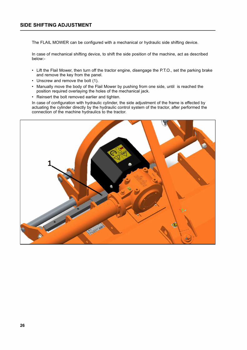
The FLAIL MOWER can be configured with a mechanical or hydraulic side shifting device.
In case of mechanical shifting device, to shift the side position of the machine, act as describedbelow:-
• Lift the Flail Mower, then turn off the tractor engine, disengage the P.T.O., set the parking brakeand remove the key from the panel.
• Unscrew and remove the bolt (1).• Manually move the body of the Flail Mower by pushing from one side, until is reached the
position required overlaying the holes of the mechanical jack.• Reinsert the bolt removed earlier and tighten.In case of configuration with hydraulic cylinder, the side adjustment of the frame is effected byactuating the cylinder directly by the hydraulic control system of the tractor, after performed theconnection of the machine hydraulics to the tractor.
26
SIDE SHIFTING ADJUSTMENT
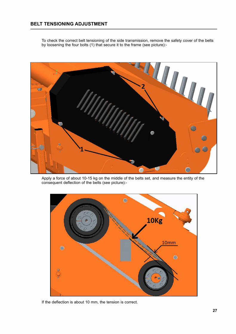
To check the correct belt tensioning of the side transmission, remove the safety cover of the beltsby loosening the four bolts (1) that secure it to the frame (see picture):-
Apply a force of about 10-15 kg on the middle of the belts set, and measure the entity of theconsequent deflection of the belts (see picture):-
If the deflection is about 10 mm, the tension is correct.
27
BELT TENSIONING ADJUSTMENT

28
BELT TENSIONING ADJUSTMENT
If is not so, proceed with the adjustment in the following way (see picture below):-
• Loosen the four nuts (1) under the gearbox which lock it to the frame.• Loosen the two bolts (2) fixing the extension tube to the side plate of the frame.• While holding the screw (3), loosen the lock nuts (4).• Tighten the tension nut (5) if the tensioning found is too low (deflection of belts higher than 10 mm).
unscrew the tension nut (5) if the tensioning found is too high (deflection of belts lower than 10 mm).• Retighten the two bolts (2) fixing the extension tube to the side plate of the frame.• Move the gearbox in order to restore the position of the extension tube perpendicular to the side
plate of the Flail Mower.• Retighten the four nuts (1) under the gearbox.• Reposition the safety cover in his original place.

29
BELT TENSIONING ADJUSTMENT
If the replacement of the set of belts is required:-
• Remove the safety cover of the belts by loosening the four bolts that secure it to the frame.• Loosen the four nuts (1) under the gearbox which lock it to the frame.• Loosen the two bolts (2) fixing the extension tube to the side plate of the frame.• Loosen the lock nuts (4) and the tension nut (5) until the extraction of the belts from their seats • Reinsert the new belts in succession contrary to what done for the disassembly.• Adjust the belt tension according to the indications done above.• Retighten the two bolts (2) fixing the extension tube to the side plate of the frame.• Move the gearbox in order to restore the position of the extension tube perpendicular to the side
plate of the Flail Mower.• Retighten the four nuts (1) under the gearbox.• Reposition the safety cover in his original place.
a

30
To stop the Flail Mower at the end of a working session:-
• Bring the tractor to a complete stop.• Place the transmission in park or neutral.• Reduce the engine speed, then disengage the P.T.O.• Wait for stopping of all rotating parts.• Lower the implement to the ground.• Set the parking brake.• Shut down the engine and remove the key before exiting the tractor.• Do the cleaning and maintenance required to make the machine ready for later use (see section
Maintenance).
WARNINGNever leave the tractor unattended with the implement in the lifted position.
To disconnect the Flail Mower from the tractor (e.g. to make a change of implement):
Adjust the parking stand to the lowest position, through the use of relative retaining pin.Park the tractor on a dry and level surface.Reduce the engine speed, then disengage P.T.O.Wait for stopping of all rotating parts.Lower the implement to the ground.Set the parking brake.Shut down the engine and remove the key before exiting the tractor.Place safety blocks under Flail Mower to prevent unit from tipping over onto a child and/or an adult.A Flail Mower that tips over can result in injury or death.Disconnect the driveline from the tractor P.T.O. and rest it on the provided support of the FlailMower.Disconnect the top link and rear lifting arms of the tractor from the Flail Mower hitches.Check the Flail Mower stability. If needed, place additional safety blocks.Get on the tractor, start the engine and move away from the Flail Mower slowly.Make sure the Flail Mower remains stored in a protected area, to prevent any unauthorisedpersonnel from approaching it.
Before a long term storage (e.g. at seasonal end), do cleaning and maintenance operations asspecified in sections MAINTENANCE and STORAGE.
STOPPING AND DISCONNECTION

31
To set the Flail Mower for transportation, perform the following steps:-
• Idle tractor engine, disengage tractor P.T.O., and wait for stopping of all rotating parts.• Lift the Flail Mower until the transport position, making sure the driveline transmission tubes
does not contact tractor or Flail Mower. A minimum gap of 2 cm should be leaved between thetubes and tractor and Flail Mower (see also section Driveline installation).
• Lock the tractor lifting hydraulics, turn off the engine, set the parking brake, remove ignition keyand get off the tractor.
• Adjust the parking stand to the highest position, through the use of relative retaining pin, toprevent its possible damage during transport.
When driving on public roads, follow strictly all local laws and traffic regulations.
WARNINGWhen driving on public roads, reduce your speed, be aware of traffic around you and proceed insuch a way that faster moving vehicles may pass you safely.
MAINTENANCE
Proper and regular maintenance ensures a long life of the equipment, avoids failures and savestime and repair costs.Periodic inspections and maintenance operations described in this section must be performed byoperator in the times and terms prescribed. Failure to comply with maintenance prescriptions cancompromise the functioning and duration of the machine, and consequently invalidate the warranty.The frequency of maintenance indicated refers to normal conditions of use: it must be intensified insevere operating conditions (frequent stops and starts, prolonged winter season etc ...).Repairs, maintenance and modifications other than those mentioned in this paragraph should NOTbe performed without consulting the Manufacturer or your Dealer. Manufacturer, as the case, maygive the authorisation to proceed with the repair together with all necessary instructions.Wrong or inappropriate repairs or maintenance may generate abnormal operating conditions,equipment damage and generate risks for the operator.
WARNINGFor safety reasons, all maintenance operations must be performed with tractor P.T.O. disengaged,Flail Mower stopped and completely lowered to the ground or onto support blocks, parking brakeset, tractor engine shut off, and ignition key removed.
IMPORTANTRespect the environment. Store or dispose of unused chemicals as specified by the chemicalManufacturer.
TRANSPORTING

Frequently check the wear condition of the blades on the rotor (Y blades or hammers) throughvisual inspection. The wear of the blades is very variable depending on the type of trash.Replacement of the blades is necessary when the operator notices increase of power absorptionduring operations, or when the blades or hammers dimension is significantly reduced compared tothe original.The use of the machine with blades in bad condition compromises the quality of the work.
Before replacing the blades:-Idle tractor engine, set the parking brake, disengage tractor P.T.O., and wait for all moving parts tocome to a complete stop.Place the machine slightly lifted from the ground on safety blocks or mechanical stands;lock the control lever of the hydraulic lift of the tractor.Turn off the tractor and remove the key from the control panel.
To perform the replacement of blades:• Remove the bolt that locks the couple of Y blades (or the hammer) in the rotor. For the Y blades,
two bushing are placed on the bolt to fill the gap between the blades and the holders of therotor.
• Place the new blade, and tighten the bolts with washers, referring to the torque values shown in“Table torques” in the manual.
• For the rotor with blades don’t forget to place the related bushings between the blades and theholders.
• For the rotor with hammers be sure to install the cutting edge facing in the direction of rotation ofthe rotor;
• Repeat this process for all the blades.
IMPORTANTRemove and install one blade/hammer at a time to ensure blades/hammers are correctly orientedwhen installed.Replace worn blades only with original parts.
WARNINGWhen the blades/hammers are worn out it is necessary to replace the full set of tools.Replacement of only some of the tools is certainly cause of the rotor unbalance, machinevibrations and can compromise the reliability of the Flail Mower and generate risks to the operator.
CAUTIONWorn blades and hammers may be very sharp!
ROTOR TOOLS REPLACEMENT
32

33
GEARBOX LUBRICATIONLubricant: SAE 85W/140 oil gear or equivalent
CAUTIONBefore touching the gearbox wait until it has cooled sufficiently.
Check the oil level every 50 hours, making sure the level is aligned with the level plug (1).To perform the check, it is necessary to remove the screws (2) holding the safety cover on thegearbox, which prevents access to the plug.
If the oil level is below the line of the level plug, it’s necessary fill up oil till restore the correct level.
The oil change must be performed:
• After the first 50 working hours.• Each 500 working hours.
To make the oil change:
• Unscrew the level plug (1).• Place a tank under the oil drain plugs (3) and (4).• Unscrew the oil drain plugs (3) and (4) and drain oil completely into the tank.• Retighten the drain plug (4).• Unscrew the oil filling plug (5) on the top of gearbox.• Fill up oil till the level reach the hole of the level plug (1).• Retighten level plug (1) and the filling plug (5).• Replace the safety cover retightening the screws (2).• Dispose the discharged oil into containers for used oil and dispose of responsibly.
IMPORTANTFrequently check possible oil leaks from the Flail Mower through visual inspection, and in case ofleakage provide immediately proper maintenance.Avoid oil leaks onto the ground when restoring the oil level or making oil changes.
MAINTENANCE

ROTOR BEARINGS LUBRICATIONLubricant: Wessex Prolube EP 2 lithium-type grease (or equivalent)Frequency: each 20 working hours
To perform lubrication (see pictures):-• Turn the cover (1) and inject grease through the nipple (2).• Inject grease through the nipple (3).
IMPORTANTMake sure to clean the fitting nipple before using the grease gun.Do not let excess grease collect on or around parts, particularly when operating in sandy areas.
ROLLER BEARINGS LUBRICATIONLubricant: Wessex Prolube EP 2 lithium-type grease (or equivalent)Frequency: each 20 working hours To perform lubrication, inject grease into the nipples (1) and (2), located on the upper part of theroller bearing supports (see pictures).
34
MAINTENANCE

3-POINT HITCH LUBRICATIONLubricant: Wessex Prolube EP 2 lithium-type grease (or equivalent).Frequency: each 20 working hours.
To perform lubrication of the shifting parts of the 3-point hitch (see pictures):-• Inject grease into the nipples (2), located on the lower part of the shifting tube of the hitch.• Inject grease into the nipples (3), located on the rod-tie of the hitch.
35
MAINTENANCE

DRIVE BELTS REPLACEMENT
Frequently check the wear of the belts, and if one or more of these appears worn replace the fullset. To replace the drive belts, refer to the section “Belts tensioning adjustment”.
DRIVESHAFT MAINTENANCE
Lubricant: Wessex Prolube EP 2 lithium-type grease (or equivalent).Frequency: each 20 working hours.
Grease crosses, sliding parts of protective shielding and driveshaft transmission tubes.
IMPORTANTFor details about maintenance and lubrication of the driveshaft, refer to the user manual of thedriveshaft Manufacturer.
NOTEFor the driveshaft service parts, refer to the user manual of the driveshaft Manufacturer.
36
MAINTENANCE
Before leaving the machine unused for a long time, it’s necessary to perform following tasks topreserve the appearance and functionality of the machine, and to make easier the restart at lateruse:-
• Park the Flail Mower on a flat surface, in a place dry and protected from exposition to theelements.
• Possibly with storage temperature between 0 and 50 °C (see section Stopping anddisconnection).
• Thoroughly clean the machine, removing from the rotor all residues due to shredding, in order toavoid damage from grass and stagnant water.
• Carefully inspect the machine, checking for worn and/or damaged parts. Perform immediately allrepairs, and/or replacements needed, in order to make the machine ready for restarting.
• In case of abrasion of painted surfaces, provide restoring the surface protection through touchuppaint.
To prevent rust:-• Make sure the safety decals are in their original positions, intact and legible. When required,
replace the decals immediately.• Lubricate properly all grease points, and restore the oil levels as indicated in the Maintenance
section. Use protective oil to coat the exposed mechanical components and to protect themagainst rust.
SCRAPPING
In case of scrapping, the machine must be disposed in appropriate and authorised sites, accordingto local legislation.Before scrapping, separate plastic parts from rubber parts, aluminum, steel, etc. Recover anddispose any exhausted oils to authorised centres for oil collecting.
37
STORAGE

38
TROUBLESHOOTING
PROBLEM POSSIBLE CAUSE POSSIBLE SOLUTION
Oil leaking from gearbox/transmission case
• Gearbox Overfilled• Loose filling/drain/levelplug• Damaged breather plug• Damaged Seals
• Drain to proper level• Replace breather plug• Tighten filling/drain/levelplug• Replace seals
Shredding not uniform
• Worn blades/hammers• Roller set at wrong height• Ground speed too fast
• Replace blades/hammers• Set the roller correctly• Reduce the ground speed
Gearbox overheating
• Low oil level• Dense material
• Add oil• Reduce forward cutting
speed
Blades/hammers frequentlywearing • Cutting height too low
• Check the soil in advance• Increase the cutting height
Noise and vibration for FlailMower noticeable and contstant
• Unbalanced roller
• Worn bearings• Blades/hammers worn,
damaged or missing
• Balance the roller inauthorised shop
• Replace bearings• Replace blades/hammers

Frequently check the Flail Mower hardware to ensure that all screws and bolts are tightenedaccording to torque values listed in the table below:-
SPARE PARTS
All repairs and replacements on the machine must be performed only by using original spare parts,which must be obtained from the Wessex International or your Dealer.This section contains the information needed to identify the parts of FLAIL MOWER that may beordered from the Manufacturer.
When requesting spare parts from the Manufacturer, always give the following information:
• Type of machine;• Serial number of Flail Mower• Part number and description.• Quantity required.
NOTEFor identification of part numbers and description of safety decals refer to the Section Safetylabels. For identification of part numbers and description of P.T.O. driveline parts, refer to themanual of the driveshaft Manufacturer.
The Manufacturer reserves the right to substitute a required part with an equivalent part, ifapplicable.
39
TORQUE VALUES TABLE
8.8 GRADE 10.9 GRADE
BOLT SIZE (METRIC) Nm Nm
M6 11 15
M8 26 36
M10 52 72
M12 91 125
M14 145 200
M16 225 315
M18 310 405
M20 440 610

4040
PARTS ILLUSTRATION - MAIN FRAME & ROTOR ASSEMBLY

41
PARTS LIST - MAIN FRAME & ROTOR ASSEMBLY
Item No. Part No. Description Qty1 SS-17334 Frame Weldment - Flail Mower - 115 11 SS-17336 Frame Weldment - Flail Mower - 130 12 SS-17142 Closing Plate - Weldment 13 SS-17270 Hex Bolt - M10 x 1.50 x 25 24 SS-8078 Plain Washer - 10mm 25 SS-17272 Hex Nut - M10 x 1.5 26 SS-17280 Hex Bolt - M14 x 2 x 30 107 SS-1272 Plain Washer - 14mm 108 SS-17400 Rotor Assembly - Y Blade - Flail Mower 115 18 SS-17399 Rotor Assembly - Y Blade - Flail Mower 130 18 SS-17341 Rotor Assembly - Hammer Blade - Flail Mower 115 18 SS-17340 Rotor Assembly - Hammer Blade - Flail Mower 130 19 SS-17338 Rotor Weldment - Flail Mower 115 19 SS-17337 Rotor Weldment - Flail Mower 130 110 SS-17149 Rotor Hub - Transmission Side 211 SS-17150 Oil Seal - 47 x 70 x 8 212 SS-17151 Bearing - 22208 213 SS-17152 Ring - Rotary Seal 114 SS-17153 Oil Seal - 50 x 72 x 8 115 SS-17154 Spacer - Driven Pulley 116 SS-12090 Grub Screw - M 6 x 1 x 10 117 SS-20272 Grease Nipple M10 x 1.5 (Straight) 218 SS-8027 External Circlip - 40mm 119 SS-17279 Hex Bolt - M16 x 2 x 90 - Flail Mower 115 1419 SS-17279 Hex Bolt - M16 x 2 x 90 - Flail Mower 130 1620 SS-1231 Nylock Nut - M16 x 2 - Flail Mower 115 1420 SS-1231 Nylock Nut - M16 x 2 - Flail Mower 130 1621 SS-17382 Set of Hammer Blades - Flail Mower 115 121 SS-17381 Set of Hammer Blades - Flail Mower 130 122 SS-17229 Blade Spacer - Flail Mower 115 2822 SS-17229 Blade Spacer - Flail Mower 130 3223 SS-17407 Set of Y Blades - Flail Mower 115 123 SS-17406 Set of Y Blades - Flail Mower 130 124 SS-17410 Hex Holder - Flail Mower 115 1424 SS-17410 Hex Holder - Flail Mower 130 1625 SS-17411 Round Holder - Flail Mower 115 1425 SS-17411 Round Holder - Flail Mower 130 1626 SS-1130 Circlip Internal - 80mm 1

42
PARTS ILLUSTRATION - TRANSMISSION AND SKID

43
Item No. Part No. Description Qty.1 SS-17374 Gearbox Assembly (345mm) 540 RPM - Flail Mower 115 11 SS-17373 Gearbox Assembly (420mm) 540 RPM - Flail Mower 130 12 SS-7018 Stud - M12 x 50 43 SS-17269 Plain Washer - 30 x 12 x 3 64 SS-1209 Nylock Nut - M12 x 1.75 85 SS-17275 Hex Bolt - M12 x 1.75 x 30 26 SS-17273 Hex Nut - M12 x 1.75 27 SS-17281 Hex Bolt - M10 x 1.50 x 60 18 SS-8078 Plain Washer 10mm 19 SS-17272 Hex Nut - M10 x 1.5 2
10 SS-17405 SPB Type Pulley - Pitch Dia 180 - 3 Grooves 111 SS-17037 Clamp Outer 212 SS-17036 Clamp Inner 213 SS-17035 Allen Bolt - M8 x 1.25 x 35 (FT) (8.8) 1414 SS-17404 SPB Type Pulley - Pitch Dia 140 - 3 Grooves 115 SS-17699 Set of V Belts - BX 47 (3 Nos) 416 SS-17403 Guard - Belt Transmission - 3 Grooves 117 SS-17165 Plate - Protection Grease Nipple 118 SS-8040 Hex Bolt - M8 x 1.25 x 20 519 SS-8064 Plain Washer - 8mm 520 SS-1297 Nylock Nut - M8 x 1.25 121 SS-8181 Hex Bolt - M8 x 1.25 422 SS-17166 Skid Weldment 223 SS-17166 Hex Bolt M12 x 1.75 x 35 424 SS-17300 Plate Weldment, Belt Tensioning 1
PARTS LIST - TRANSMISSION AND SKID

44
PARTS ILLUSTRATION - GEARBOX

45
Item No. Part No. Description Qty. 1 SS-17001 Gearbox - 540 RPM (SRM) 50HP 12 SS-17244 Input Shaft (SRM) 540 RPM 13 SS-17577 Crown - 36 Teeth - Free Wheel 14 SS-17576 Pinion Shaft - 12 Teeth (SRM) 50HP 15 SS- 17230 Ratchet - 28mm 26 SS-8027 Circlip External - 40mm 17 SS-1131 Bearing - 6307 28 SS-17002 Gearbox Flange 540 RPM (SRM) 50HP 19 SS-1130 Circlip Internal - 80mm 2
10 SS-17329 Oil Seal - 35 x 80 x 10 111 SS-17167 Shims (Dia 80 x 65) (0.5mm) 612 SS-17633 Oil Seal - 80 x 10 213 SS-17054 Bearing - 32207B 114 SS-10143 Bearing - 6207 115 SS-1424 Shims (Dia 44.5 x 35.7) (0.50mm) 216 SS-6024 Circlip External 35mm 117 SS-14309 Oil Seal - 35 x 72 x 8 118 SS-14311 Air Breather 3/8” BSP 219 SS-17258 Plug 220 SS-17083 Circlip Internal - 32mm 121 SS-17025 Shaft Connector (SRM) 122 SS-11077 Parallel Key 10 x 8 x 56 123 SS-17363 Jack Shaft - 335mm - Flail Mower 115 123 SS-17362 Jack Shaft - 410mm - Flail Mower 130 124 SS-11076 Parallel Key 12 x 8 x 40 125 SS-17366 Jack Shaft Housing Weldment - 345mm - Flail Mower 115 125 SS-17365 Jack Shaft Housing Weldment - 420mm - Flail Mower 130 126 SS-8036 Bearing - 6308 127 SS-3027 Circlip Internal - 90mm 128 SS-17026 Oil Seal 90 x 40 x 8 (SKF) 129 SS-17027 Allen Bolt - M12 x 1.75 x 30 (FT) (8.8) 430 SS-17270 Hex Bolt - M10 x 1.50 x 25 831 SS-1425 Shims (Dia 45 x 35) (1.0mm) 132 SS-17076 Leaf Spring (SRM) 233 SS-17677 Gearbox Assembly - 50HP 134 SS-17675 Plastic Cap M12 x 1.75 835 SS-17785 Jack Shaft Housing Assembly - 335mm - Flail Mower 115 135 SS-17784 Jack Shaft Housing Assembly - 410mm - Flail Mower 130 1
PARTS LIST - GEARBOX

46
PARTS ILLUSTRATION - 3 POINT MAST ASSEMBLY

47
Item No. Part No. Description Qty. 1 SS-17180 Mast Weldment - Hydraulic (SFM) 12 SS-17181 Bushing - (Dia = 40, Depth = 60, L=60) (SFM) 23 SS-12127 ‘O’ Ring - 52 x 3.5 44 SS-17182 Oil Seal - 40 x 55 x 7 25 SS-8120 Circlip Internal - 62mm 26 SS-17183 Guide Bar - (L=1080mm) (SFM) 17 SS-17184 Bracket - Left Hand - (SFM) 18 SS-17185 Bracket Weldment - (SFM) 19 SS-17277 Hex Bolt - M16 x 1.50 x 45 210 SS-17578 Hydraulic Jack (Stroke 300) 111 SS-17417 Hex Bolt - M14 x 1.5 x 65 (8.8) DIN 931 212 SS-1302 Nylock Nut - M14 x 1.5 213 SS-17278 Hex Bolt - M16 x 2 x 50 414 SS-1078 Plain Washer - 16mm 415 SS-1231 Nylock Nut - M16 x 2 416 SS-17188 Hydraulic Pipe - Complete - 2000mm 117 SS-17189 Hydraulic Pipe - Complete - 2400mm 118 SS-8290 Quick Coupling 1/2” Male 219 SS-18269 QRC Plastic Cap (1/2” BSP) Female 220 SS-20148 Grease Nipple - M8 221 SS-17266 Manual Jack Assembly 122 SS-17264 Outer Pipe Manual Jack Complete 123 SS-17265 Inner Pipe Manual Jack Complete 124 SS-17301 Hex Bolt - M10 x 1.50 x 55 (8.8) DIN 931 125 SS-17272 Hex Nut - M10 x 1.50 - DIN 934 126 SS-23146 Driveline Hook - Jumbo 127 SS-23147 Plate - Hook Holding - Jumbo 128 SS-23029 Hex Bolt - M4 x 0.75 x 10 129 SS-23028 Hex Nut - M4 x 0.75 130 SS-17268 Hydraulic Parts Assembly Kit 131 SS-1308 Spring Washer - 16mm 232 SS-1307 Spring Washer - 14mm 233 SS-26030 Manual Box Cover - 1/2 (SMMSD) 134 SS-8064 Plain Washer - 8mm 335 SS-8190 Hex Bolt - M8 x 1.25 x 15 3
PARTS LIST - 3 POINT MAST ASSEMBLY

48
PARTS ILLUSTRATION - 3 POINT MAST ASSEMBLY

49
PARTS LIST - 3 POINT MAST ASSEMBLY
Item No. Part No. Description Qty. 1 SS-17233 3 Point Mast Hydraulic Assembly 12 SS-17190 Tie Rod With Ball Joints (SFM) 13 SS-17278 Hex Bolt - M16 x 2 x 50 44 SS-1078 Plain Washer - 16mm 45 SS-1231 Nylock Nut - M16 x 2 46 SS-17191 Dowel Pin - (Dia 8 x 36) 27 SS-14015 Hitch Pin - Bottom CAT-I (Dia 22 x 99) 28 SS-14037 Hitch Pin - Top CAT-I (Dia 19 x 98) 19 SS-1218 Lynch Pin 310 SS-17260 3 Point Mast Assembly - Fix Type (SFM) 111 SS-17234 Mast Weldment - Fix Type (SFM) 112 SS-17235 Bracket - Lower 3rd Point Attachment (SFM) 413 SS-18446 Hex Bolt - M16 x 2 x 55 (8.8) 614 SS-14086 Bush - (19.4 x 25.4 x 52L) 115 SS-15069 Bush 2

50
PARTS ILLUSTRATION - SHIELD, FRONT PLATES, PARKING STAND

51
Item No. Part No. Description Qty. 1 SS-1547 Shield Implement Input Connection 12 SS-8190 Hex Bolt - M8 x 1.25 x 15 43 SS-8064 Plain Washer - 8mm 44 SS-17359 Rod - Front Plates - Flail Mower 115 14 SS-17358 Rod - Front Plates - Flail Mower 130 15 SS-17197 Front Plate (L =100) - Flail Mower 115 105 SS-17197 Front Plate (L =100) - Flail Mower 130 116 SS-17198 Front Plate (L =85) - Flail Mower 115 06 SS-17198 Front Plate (L =85) - Flail Mower 130 17 SS-15055 Cotter Pin (Dia 5 x 40) 18 SS-14013 M/C Stand Pipe Complete (U-Series) 19 SS-14267 Square Snapper Pin (D=10, L=70) 110 SS-14266 Square Pipe Plastic Cap - 32mm 111 SS-1545 PTO Shaft Guard 112 SS-1546 PTO Shaft Guard Mount Plate Complete 1
PARTS LIST - SHIELD, FRONT PLATES, PARKING STAND

52
PARTS ILLUSTRATION - REAR COVER

53
PARTS LIST - REAR COVER
Item No. Part No. Description Qty. 1 SS-17344 Standard Rear Cover Weldment - Flail Mower 115 11 SS-17343 Standard Rear Cover Weldment - Flail Mower 130 12 SS-17276 Hex Bolt - M10 x 1.50 x 20 33 SS-8078 Plain Washer - 10mm 34 SS-23318 Hex Bolt - M14 x 1.50 x 40 (8.8) DIN 931 45 SS-1272 Plain Washer - 14mm 66 SS-1302 Nylock Nut - M14 x 1.5 67 SS-17282 Hex Bolt - M4 x 1.50 x 30 (8.8) DIN 933 28 SS-17379 Standard Rear Cover Assembly - Flail Mower 115 18 SS-17378 Standard Rear Cover Assembly - Flail Mower 130 1

54
PARTS ILLUSTRATION - REAR ROLLER ASSEMBLY

55
PARTS LIST - REAR ROLLER ASSEMBLY
Item No. Part No. Description Qty. 1 SS-17356 Rear Roller Assembly - Flail Mower 115 11 SS-17355 Rear Roller Assembly - Flail Mower 130 12 SS-23318 Hex Bolt - M14 x 1.50 x 40 43 SS-1272 Plain Washer - 14mm 44 SS-1302 Nylock Nut - M14 x 1.5 45 SS-17352 Rear Roller Weldment - Flail Mower 115 15 SS-17353 Rear Roller Weldment - Flail Mower 130 16 SS-17214 Bearing - UC - 206mm 27 SS-17215 Roller Mount Weldment - Left Hand 18 SS-17216 Roller Mount Weldment -Right Hand 19 SS-17350 Scraper - Flail Mower 115 19 SS-17349 Scraper - Flail Mower 130 1
10 SS-17274 Hex Bolt - M12 x 1.75 x 35 211 SS-8126 Plain Washer - 12mm 2 12 SS-1209 Nylock Nut - M12 x 1.75 213 SS-20272 Grease Nipple - M10 x 1.5 - (Straight) 214 SS-14119 Oil Seal - 72 x 8 2

56
PARTS ILLUSTRATION - REAR COVER WITH RACKS

57
PARTS LIST - REAR COVER WITH RACKS
Item No. Part No. Description Qty.
1 SS-17347 Racks Rear Cover - Weldment - Flail Mower 115 11 SS-17346 Racks Rear Cover - Weldment - Flail Mower 130 12 SS-23318 Hex Bolt - M14 x 1.50 x 40 63 SS-1272 Plain Washer - 14mm 64 SS-1302 Nylock Nut - M14 x 1.5 65 SS-8010 Hex Bolt - M10 x 1.50 x 20 36 SS-8078 Plain Washer - 10mm 37 SS-17227 Rack - (D=22, L=350) - Flail Mower 115 77 SS-17227 Rack - (D=22, L=350) - Flail Mower 130 88 SS-15055 R-Clip Wire - (Dia 4.00mm) - Flail Mower 115 78 SS-15055 R-Clip Wire - (Dia 4.00mm) - Flail Mower 130 89 SS-17282 Hex Bolt - M14 x 1.5 x 30 (8.8) DIN 933 210 SS-17376 Rear Cover With Racks Assembly- Flail Mower 115 110 SS-17375 Rear Cover With Racks Assembly- Flail Mower 130 1

58
P.T.O. SHAFT OPERATION AND MAINTENANCE
IMPORTANT!
P.T.O. drive shafts must only be used for their intended purpose.
P.T.O. drive shafts are designed for specific machine types and power requirements.They must not be replaced by other models.Ensure that the P.T.O. drive shaft is securely connected.
Only use a completely protected drive system:
P.T.O. drive shaft with complete guard and complementary guard on tractor andimplement. A complete guard is essential in all working positions.
LUBRICATION
Lubricate with quality grease before starting work and every 40 operating hours.
Ensure the P.T.O. guard bearings are lubricated, the end ballshaped covers need retracting to expose all grease nipples.
Clean and grease the P.T.O. drive shaft before each prolonged period of non-use.
Grease the guard tubes in winter to prevent freezing.
COUPLING THE P.T.O. SHAFT
Clean and grease the P.T.O. and PIN
Q.-d pinPress q.-d. pin and simultaneously push P.T.O.drive shaft onto P.T.O. until pin engages.

59
P.T.O. SHAFT OPERATION AND MAINTENANCE
LENGTH ADJUSTMENT
To adjust the length, hold the half-shafts next to each other in theshortest working position and mark them.
Shorten inner and outer guard tubes equally.
Shorten inner and outer sliding profiles by the same length as the guard tubes.
Round off all sharp edges and remove burrs.Grease sliding profiles.
No other changes may be made to the P.T.O. drive shaft and guard.
CHAINS
Chains must be fitted so as to allow sufficient articulation of the shaft in all working positions.
Do not let the chains encircle the P.T.O. guard in use as this willshorten the life of the P.T.O. guard.
The P.T.O. drive shaft must not be suspended from the chains! Please use the P.T.O. Support Hook provided.

60
The undersigned personnel have been trained in the safe use of this Wessex machine and haveunderstood the contents of the Operator’s Manual.
SAFETY TRAINING INDUCTION
OPERATOR INSTRUCTOR/TRAINERDate Name Signature Name Signature

61
DAILY INSPECTION RECORD
OPERATOR’S NAME
DATE OFINSPECTION
HOURS
Spin
dle
Rot
or, r
emov
e ta
ngle
dob
ject
s
Insp
ect c
ondi
tion
of B
lade
s
All b
olts
and
nut
s, re
-tigh
ten
if re
q’d.
Gre
ase
Rot
or B
earin
gs
Gre
ase
Rol
ler B
earin
gs
Che
ck G
earb
ox O
il Le
vel
Insp
ect c
ondi
tion
of B
elts
Insp
ect t
ensi
on o
f Bel
ts

WFM 115, 130
FLAIL MOWER
APRIL 2017

Wessex InternationalCharlton House, Caxton Close, East Portway Industrial Estate, Andover Hampshire. SP10 3QN
Telephone: 01264 345870 Fax 01264 345880e-mail: [email protected]
www.wessexintl.com