Embed Size (px)
Citation preview

Big Lift LLC MANUAL NO. BL-D40-0515 - 11-29-2018www.bigjoeforklifts.com
D40SELF-PROPELLED,
PALLET LIFT TRUCK
U.S. Patents Nos. D739,112; D770,719; D770,720; 9,586,605
Operation
Maintenance
Repair Parts List
NOTE: For the most current parts information and service updates, please refer to the Big JoeSupport site at www.bigjoesupport.com
WARNING
Do not operate this truck unless you have been autho-rized and trained to do so, and have read all warningsand instructions in Operator’s Manual and on thistruck.
Do not operate this truck until you have checked itscondition. Give special attention to wheels, horn, bat-tery, controller, lift system, brakes, steering mecha-nism, guards and safety devices.
Operate truck only from designated operating position.Do not carry passengers. Keep feet clear of truck andwear foot protection.
Observe applicable traffic regulations. Yield right ofway to pedestrians. Slow down and sound horn atcross aisles and wherever vision is obstructed.
Start, stop, travel, steer and brake smoothly. Slowdown for turns and on uneven or slippery surfaces thatcould cause truck to slide or overturn. Use special
care when traveling without load as the risk of overturnmay be greater.
Always look in direction of travel. Keep a clear view,and when load interferes with visibility, travel with loadtrailing.
Use special care when operating on ramps travelslowly, and do not angle or turn. Travel with loaddownhill.
Do not handle loads which are higher than the chassisunless load is secured so that no part of it could fallbackward. Before lifting, be sure load is centered,forks are completely under the chassis backrest.
When leaving truck, neutralize travel control, fullylower lifting mechanism and set brake. When leavingtruck unattended, also shut off power.

TABLE OF CONTENTS
Section Page Section Page
1 LIST OF ILLUSTRATIONS..........................................1-II
1 LIST OF TABLES ........................................................1-II
1DESCRIPTION1-1
1-1. INTRODUCTION. .........................................1-11-2. GENERAL DESCRIPTION. ..........................1-11-3. SAFETY FEATURES....................................1-2
2OPERATION2-1
2-1. GENERAL.....................................................2-12-2. OPERATING PRECAUTIONS......................2-12-3. BEFORE OPERATION.................................2-12-4. GENERAL CONTROL OPERATION............2-42-5. DRIVE AND STOPPING PROCEDURES. ...2-42-6. BELLY-BUTTON SWITCH. ..........................2-42-7. STEERING ARM GAS SPRING. ..................2-52-8. LIFT AND LOWER CONTROLS...................2-52-9. BACKREST. .................................................2-52-10. GUIDE RAILS. ..............................................2-52-11. LOADING AND UNLOADING.......................2-52-12. PARKING......................................................2-5
3PLANNED MAINTENANCE3-1
3-1. GENERAL.....................................................3-13-2. MONTHLY AND QUARTERLY CHECKS.....3-13-3. BATTERY CARE. ........................................3-13-3.1. GENERAL.....................................................3-13-3.2. SAFETY RULES...........................................3-23-3.3. BATTERY CARE AND CHARGING .............3-23-3.4. BATTERY CLEANING..................................3-23-3.5. MAINTENANCE FREE BATTERIES............3-23-4. CHARGING BATTERIES .............................3-33-5. BATTERIES REPLACEMENT......................3-43-6. LUBRICATION..............................................3-5
4TROUBLESHOOTING4-1
4-1. GENERAL.....................................................4-14-2. CONTROLLER TROUBLESHOOTING........4-44-2.1. ZAPI HANDSET............................................4-44-2.2. FAULT DETECTION.....................................4-44-2.3. TESTING TRUCK OPERATION...................4-44-2.4. SETTINGS AND ADJUSTMENTS................4-5
5STEERING ARM, CONTROL HEAD AND COMPART.....5-1
5-1. CONTROL HEAD .........................................5-15-1.1. CONTROL HEAD REMOVAL.......................5-15-1.2. CONTROL HEAD INSTALLATION...............5-35-1.3. CAP ASSEMBLY REMOVAL. ......................5-35-1.4. CAP ASSEMBLY INSTALLATION. ..............5-35-1.5. SPEED POTENT. REPLACEMENT. ...........5-35-1.6. BELLY-BUTTON SWITCH REPLACE..........5-35-1.7. HORN SWITCH REPLACEMENT. ...............5-45-1.8. LIFT / LOWER SWITCH REPLACEMENT...5-5
5-2. COMPARTMENT COVERS......................... 5-65-2.1. REMOVAL.................................................... 5-65-2.2. INSTALLATION............................................ 5-65-3. STEERING ARM.......................................... 5-75-3.1. RETURN SPRING REPLACEMENT. .......... 5-75-3.2. STEERING ARM REMOVAL. ...................... 5-75-3.3. STEERING ARM INSTALLATION. .............. 5-7
6BRAKE SERVICING6-1
6-1. BRAKES....................................................... 6-16-1.1. AIR GAP ADJUSTMENT. ............................ 6-16-1.2. STOPPING DISTANCE ADJUSTMENT. ..... 6-26-1.3. BRAKE ASSEMBLY REPLACEMENT......... 6-2
7TRANSMISSION, DRIVE AND LOAD WHEEL................ 7-1
7-1. LOAD WHEEL.............................................. 7-27-1.1. REMOVAL.................................................... 7-27-1.2. REPAIR....................................................... 7-27-1.3. LOAD WHEEL INSTALLATION................... 7-27-2. DRIVE WHEEL. ........................................... 7-37-3. TRANSMISSION.......................................... 7-3
8ELEVATION SYSTEM SERVICING8-1
8-1. GENERAL.................................................... 8-18-2. LIFT LINKAGE ............................................. 8-18-2.1. REMOVAL.................................................... 8-18-2.2. REPAIR........................................................ 8-28-2.3. INSTALLATION............................................ 8-2
9HYDRAULIC SYSTEM SERVICING9-1
9-1. LINES AND FITTINGS................................. 9-19-2. HYDR. AND ELECTR. ASSY. REMOVAL... 9-29-2.1. REMOVAL.................................................... 9-29-2.2. INSTALLATION............................................ 9-29-3. HYDR. PUMP, MOTOR, AND
RESERVOIR ASSY ..................................... 9-29-3.1. REMOVAL.................................................... 9-29-3.2. DISASSEMBLY AND REASSEMBLY.......... 9-29-3.3. INSTALLATION............................................ 9-49-3.4. LIFT CYLINDER........................................... 9-4
10ELECTRICAL COMPONENTS....................................... 10-1
10-1. ELECTRICAL CONTROL PANEL.............. 10-110-1.1. MAINTENANCE......................................... 10-110-1.2. CLEANING................................................. 10-110-1.3. CONTROLLER REMOVAL. ....................... 10-110-1.4. CONTROLLER INSTALLATION. ............... 10-110-1.5. CHARGER REMOVAL............................... 10-110-1.6. CHARGER INSTALLATION....................... 10-110-1.7. EMERG. DISCONNECT REMOVAL.......... 10-210-1.8. EMERG. DISCONNECT INSTALLATION.. 10-210-1.9. CONTACTOR REMOVAL.......................... 10-210-1.10. CONTACTOR INSTALLATION.................. 10-210-1.11. FUSE REMOVAL. ...................................... 10-2
BL-D40-0515 - 11-29-2018 i

TABLE OF CONTENTS - Continued
10-1.12. FUSE INSTALLATION. .............................. 10-210-1.13. COOLING FAN REMOVAL........................ 10-410-1.14. COOLING FAN INSTALLATION................ 10-410-1.15. BUZZER REMOVAL. ................................. 10-410-1.16. BUZZER INSTALLATION. ......................... 10-410-1.17. KEY SWITCH REMOVAL. ......................... 10-410-1.18. KEY SWITCH INSTALLATION. ................. 10-410-1.19. BATTERY INDICATOR REMOVAL. .......... 10-410-1.20. BATTERY INDICATOR INSTALLATION. .. 10-410-1.21. LIFT LIMIT SWITCH REMOVAL................ 10-610-1.22. LIFT LIMIT SWITCH INSTALLATION........ 10-6
10-2. PUMP MOTOR...........................................10-710-3. DRIVE MOTOR. .........................................10-710-4. DEADMAN SWITCH ..................................10-710-4.1. REPLACEMENT.........................................10-7
11OPTIONAL EQUIPMENT ...............................................11-1
12ILLUSTRATED PARTS BREAKDOWN ..........................12-1
LIST OF ILLUSTRATIONS
Figure Page Figure Page
1-1 NAME PLATE ..................................................... 1-11-2 D40 LIFT TRUCK................................................. 1-12-1 SAMPLE OF OPERATOR CHECK LIST ............. 2-32-2 FORWARD/REVERSE CONTROL...................... 2-42-3 PUSHBUTTON SWITCHES ................................ 2-42-4 BRAKE ACTUATION ........................................... 2-42-5 BELLY-BUTTON SWITCH................................... 2-53-1 CHARGING BATTERY ........................................ 3-33-2 COVER REMOVAL.............................................. 3-43-3 CONTROLLER BOARD REMOVAL .................... 3-43-4 LUBRICATION DIAGRAM ................................... 3-64-1 ZAPI CONTROLLER ........................................... 4-44-2 ZAPI HANDSET................................................... 4-54-3 ZAPI HANDSET................................................... 4-94-4 THROTTLE REGULATION................................ 4-104-5 ZAPI HANDSET................................................. 4-114-6 ZAPI CONTROLLER CONNECTIONS.............. 4-135-1 STEERING ARM.................................................. 5-15-2 CONTROL HEAD ................................................ 5-25-3 EMERGENCY REVERSE SWITCH ASSY. ......... 5-45-4 CAP ASSEMBLY ................................................. 5-55-5 COMPARTMENT COVER ................................... 5-66-1 BRAKE ASSEMBLY ............................................ 6-17-1 WHEEL ASSEMBLY............................................ 7-27-2 TRANSMISSION MOTOR, BRAKE MOUNTING. 7-48-1 FRAME ................................................................ 8-18-2 LIFT LINKAGE ASSEMBLY................................. 8-29-1 HYDRAULIC SYSTEM ........................................ 9-1
9-2 PUMP & MOTOR ASSY....................................... 9-39-3 LIFT CYLINDER................................................... 9-510-1 ELECTRICAL COMPONENTS (SHEET 1) ........ 10-310-2 ELECTRICAL COMPONENTS (SHEET 2) ........ 10-510-3 ELECTRIC SYSTEM.......................................... 10-612-1 STEERING ARM ................................................ 12-212-2 CONTROL HEAD............................................... 12-412-3 CAP ASSEMBLY................................................ 12-812-4 EMERGENCY REVERSE SWITCH
ASSEMBLY ...................................................... 12-1012-5 TRANSMISSION MOTOR, BRAKE
MOUNTING...................................................... 12-1212-6 TRANSMISSION .............................................. 12-1412-7 COMPARTMENT COVERS ............................. 12-1812-8 LOAD BACKREST ........................................... 12-2012-9 FRAME............................................................. 12-2412-10 LIFT LINK ASSEMBLY..................................... 12-2612-11 LOAD WHEEL.................................................. 12-2812-12 CASTER........................................................... 12-3012-13 HYDRAULIC SYSTEM..................................... 12-3212-14 PUMP & MOTOR ASSY................................... 12-3412-15 LIFT CYLINDER............................................... 12-3612-16 ELECTRICAL SYSTEM ................................... 12-3812-17 MOTOR ASSEMBLY........................................ 12-4012-18 ELECTRICAL COMPONENTS (SHEET 1) ...... 12-4212-19 ELECTRICAL COMPONENTS (SHEET 2) ...... 12-4412-20 WIRING HARNESS.......................................... 12-4812-21 WIRING CABLES............................................. 12-50
LIST OF TABLES
Table Page Table Page
2-1 OPERATOR CHECKS ........................................... 2-23-1 MONTHLY AND QUARTERLY INSPECTION
AND SERVICE CHART.......................................... 3-13-2 RECOMMENDED LUBRICANTS........................... 3-53-3 LUBRICATION CHART.......................................... 3-6
4-1 TROUBLESHOOTING CHART ..............................4-14-2 SET OPTIONS........................................................4-54-3 ADJUSTMENTS .....................................................4-94-4 PARAMETER ADJUSTMENTS............................4-114-5 ZAPI CONTROLLER CONNECTOR PINS...........4-13
ii BL-D40-0515 - 11-29-2018

SECTION 1DESCRIPTION
1-1. INTRODUCTION.
This publication describes the 24 volt D40 lift truck dis-tributed by Big Lift LLC. Included are operating instruc-tions, planned maintenance instructions, lubricationprocedures, corrective maintenance procedures and acomplete parts list with part location illustrations.
Users shall comply with all requirements indicated inapplicable OSHA standards and current edition ofA.N.S.I. B56.1 Part II. By following these requirementsand the recommendations contained in this manual,you will receive many years of dependable servicefrom your D40 lift truck.
1-2. GENERAL DESCRIPTION.
The self-propelled D40 truck, Figure 1-2, lifts andtransports payloads up to 4000 pounds on rigid forks.
The forward and reverse motion is controlled by eitherof two controller levers mounted on the control head.Stopping and turning is controlled by the steering arm.Lift and Lower is controlled by pushbuttons on the con-trol head. The battery powered lift truck is quiet andreliable.
The reversible AC motor propels the lift truck in for-ward or reverse direction throughout the availablespeed range. The D40 lift truck can be driven with
forks raised or lowered. The lift truck must be pro-tected from the elements.
The model number will be found on the name plate(Figure 1-1) along with the serial number, lifting capac-ity, and load center. Figure 1-2 shows the locations ofthe truck’s main components and controls.
Figure 1-1 Name Plate
Figure 1-2 . D40 Lift Truck
R6209
D40-9
BL-D40-0515 - 11-29-2018 1-1

1-3. SAFETY FEATURES.
The D40 is designed and engineered to provide maxi-mum safety for operator and payload. Some of thesafety features incorporated into the design are:
• Dead-man brake to apply the brake and cut off drivepower when the steering arm is released.
• Belly-button switch to reverse truck should the oper-ator accidentally pin himself against a wall orobstruction when backing up in slow speed.
• All control functions automatically return to “OFF”when released.
• Emergency Disconnect within operator's reach.
• Readily accessible horn button.
• Handle to provide a firm hand hold for operator.
• Flow control valve regulates maximum loweringspeed within prescribed limits.
• Relief valve maintains hydraulic pressure within pre-scribed limits.
• High visibility color scheme of truck provides visualalert of truck’s presence.
• Battery Indicator.
• Adjustable load backrest.
1-2 BL-D40-0515 - 11-29-2018

SECTION 2OPERATION
2-1. GENERAL.
This section gives detailed operating instructions forthe D40 lift truck. The instructions are divided into thevarious phases of operations, such as operating lift,driving, and stopping. Routine precautions areincluded for safe operation.
2-2. OPERATING PRECAUTIONS.
WARNING: Improper operation of the lift truck mayresult in operator injury, or load and/or lifttruck damage. Observe the followingprecautions when operating the D40 lifttruck.
The following safety precautions must be adhered toat all times.
• Do not operate this truck unless you have beentrained and authorized to do so and have read allwarnings and instructions in this manual and on thetruck.
• All warnings and instructions must be read andunderstood before using the equipment.
• Equipment must be inspected by a qualified personon a regular basis.
• Do not operate this truck until you have checked itscondition. Give special attention to Wheels, Horn,Batteries, Controller, Lift System, Brakes, SteeringMechanism, Guards and Safety Devices
• Operate truck only from designated operating posi-tion. Do not carry passengers. Keep feet clear oftruck and wear foot protection.
• Observe applicable traffic regulations. Yield right ofway to pedestrians. Slow down and sound horn atcross aisles and wherever vision is obstructed.
• Start, stop, travel, steer and brake smoothly. Slowdown for turns and on uneven or slippery surfacesthat could cause truck to slide or overturn. Use spe-cial care when traveling without load as the risk ofoverturn may be greater.
• Always look in direction of travel. Keep a clear view,and when load interferes with visibility, travel withload or lifting mechanism trailing.
• Do not overload truck. Check nameplate for loadweight and load center information.
• Before lifting, be sure load is centered, forks arecompletely under load, and load is as far back aspossible against the chassis.
• Do not handle loads which are higher than the chas-sis unless load is secured so that no part of it couldfall backward.
• When leaving truck, neutralize travel control. Fullylower lifting mechanism and set brake. When leavingtruck unattended, turn off key switch and disconnectswitch, and remove key.
• The lift truck must be protected from the elements.
2-3. BEFORE OPERATION
Table 2-1 covers important inspection points on theD40 lift truck which should be checked prior to opera-tion. Depending on use, some trucks may requireadditional checks.
Figure 2-1 shows a sample format for an OperatorChecklist, which can be modified as necessary to fityour operation.
WARNING: Periodic maintenance of this truck by aQUALIFIED TECHNICIAN is required.
CAUTION: A QUALIFIED SERVICE TECHNICIANshould check the truck monthly forproper lubrication, proper fluid levels,brake operation, motor maintenance andother areas specified in the SECTION 3.
WARNING: If the truck is found to be unsafe and inneed of repair, or contributes to anunsafe condition, report it immediately tothe designated authority. Do not operateit until it has been restored to a safeoperating condition. Do not make anyunauthorized repairs or adjustments. Allservice must be performed by a qualifiedmaintenance technician.
BL-D40-0515 - 11-29-2018 2-1

Table 2-1 Operator Checks
ITEM PROCEDURE
Transmission and hydraulic systems.
Check for signs of fluid leakage.
Forks Check for cracks and damage.
Safety signs Check that warning labels, nameplate, etc., are in good condition and legible.
Horn Check that horn sounds when operated.
Steering Check for binding or looseness in steering arm when steering.
Travel controls Check that speed controls on control head operate in all speed ranges in forward and reverse and that belly button switch functions.
Wheels Check drive wheel for cracks or damage. Move truck to check load for freedom of rotation.
Hydraulic controls
Check operation of lift and lower to their maximum positions.
Brake Check that brake actuates when steering arm is raised to upright position, and when lowered to horizontal position.
Deadman/Parking brake
Check that steering arm raises to upright position when released and brake applies.
Battery disconnect
Check that battery can be disconnected and recon-nected. Check for connector damage.
Battery charge Check the battery indicator.
ITEM PROCEDURE
2-2 BL-D40-0515 - 11-29-2018

Figure 2-1 Sample of Operator Check List
R6479
BL-D40-0515 - 11-29-2018 2-3

2-4. GENERAL CONTROL OPERATION.
The speed control (See Figure 2-2) located on eachside of the control head provides fingertip control fordriving the truck. Rotate the control in the direction youwant to travel. The farther you rotate the control fromthe neutral position, the faster the truck will travel.
Figure 2-2 Forward/Reverse Control
The pushbutton switches (See Figure 2-3), located onthe front of the control head activate the lift-lower con-trols and the horn.
Figure 2-3 Pushbutton Switches
The brake is fully applied by lowering or raising thesteering arm. (See Figure 2-4) All traction controlpower is shut off when the brake is engaged. Whenthe steering arm is in the upright position, the brakeacts as a parking brake. Deadman braking occurswhen the handle is released and spring action raisessteering arm to the upright position.
Figure 2-4 Brake Actuation
2-5. DRIVING AND STOPPING PROCEDURES.
1. Turn on the emergency disconnect and the keyswitch. Grasp the grips of the steering head sothat the speed control can be comfortably oper-ated by either thumb.
2. Lower the steering arm to a comfortable positionabove horizontal to disengage the brake and toenergize the electrical circuits. If the truck is notmoved, the electrical circuits will time out and willdeenergize. See Figure 2-4.
3. To move forward (with load in front), slowly pressthe speed control forward. See Figure 2-2. Pressthe forward speed control farther to increasespeed.
4. To slow down or stop, release the speed controland lower or raise the steering arm to the horizon-tal or vertical position. See Figure 2-4. In thosepositions, the brake engages, slowing or stoppingthe truck.
5. Procedures for movement in reverse are thesame as in the forward direction except slowlypress the speed control backward. See Figure 2-2.
2-6. BELLY-BUTTON SWITCH.
The belly-button switch (Figure 2-5) minimizes thepossibility of the driver being pinned by the steeringarm while driving the lift truck in slow speed. If theswitch presses against the operator while the lift truckis being driven toward the operator, the switchchanges the direction of the lift truck.
R6617
R6618
D40-10
2-4 BL-D40-0515 - 11-29-2018

Figure 2-5 Belly-Button Switch
2-7. STEERING ARM GAS SPRING.
The steering arm gas spring automatically raises thesteering arm to the upright position when the steeringarm is released. If the steering arm does not returnfully, the steering arm gas spring requires replace-ment. Return truck to maintenance for repair.
2-8. LIFT AND LOWER CONTROLS.
Lift/Lower Control buttons are located on the steeringcontrol head. (Figure 2-3)
To lift forks, push in either LIFT button and hold untilforks reach desired height. To lower forks, push ineither LOWER button and hold until forks descend todesired height.
2-9. BACKREST.
A load backrest (Figure 12-9) is optional.
2-10.LOADING AND UNLOADING.
1. Move truck to location where load is to be pickedup.
2. Move the truck into position so forks are withinpallet or skid, and the load is centered over theforks and as far back as possible.
3. Raise forks to lift load.
4. Drive to area where load is to be placed.
5. Move truck to align load with its new position.
6. Lower the load until it rests squarely in place andthe forks are free.
7. Slowly move the truck out from under the load.
2-11.PARKING.
When finished with moving loads, return the truck to itsmaintenance or storage area. Turn off the emergencyDisconnect and the key switch. Charge batteries asnecessary. Refer to battery care instructions, SEC-TION 3.
R6619
BL-D40-0515 - 11-29-2018 2-5

NOTES
2-6 BL-D40-0515 - 11-29-2018

SECTION 3PLANNED MAINTENANCE
3-1. GENERAL.
Planned maintenance consists of periodic visual andoperational checks, parts inspection, lubrication, andscheduled maintenance designed to prevent or dis-cover malfunctions and defective parts. The operatorperforms the checks in SECTION 2, and refers anyrequired servicing to a qualified maintenance techni-cian who performs the scheduled maintenance andany required servicing.
3-2. MONTHLY AND QUARTERLY CHECKS.
Table 3-1 iis a monthly and quarterly inspection andservice chart based on normal usage of equipmenteight hours per day, five days per week. If the lift truckis used in excess of forty hours per week, the fre-quency of inspection and service should be increasedaccordingly. These procedures must be performed bya qualified service technician or your Big Lift LLC Ser-vice Representative.
3-3. BATTERY CARE.
3-3.1. General
The D40 may be equipped with maintenance free orindustrial wet cell batteries.
The care and maintenance of the battery is veryimportant to obtain efficient truck operation and maxi-mum battery life.
CAUTION: Gases produced by a battery can beexplosive. Do not smoke, use an openflame, create an arc or sparks in thevicinity of the battery. Ventilate anenclosed area well when charging.
CAUTION: Batteries contain sulfuric acid which maycause severe burns. Avoid contact witheyes, skin or clothing. In case of contact,flush immediately and thoroughly withclean water. Obtain medical attentionwhen eyes are affected. A baking sodasolution (one pound to one gallon ofwater) applied to spilled acid until bub-bling stops, neutralizes the acid for safehandling and disposal.
Leakage voltage from battery terminals to battery casecan cause misleading trouble symptoms with the truckelectrical system. Since components of the truck elec-trical system are insulated from truck frame, leakagevoltage will not normally affect truck operation unless ashort circuit or breakdown of circuit wire insulation totruck frame occurs.
A voltage check from battery connector terminal tobattery case should indicate near zero volts. Typically,however, the sum of the voltages at both terminals willequal battery volts. This leakage voltage will dischargethe battery. As battery cleanliness deteriorates, theusable charge of the battery decreases due to thisself-discharge.
Table 3-1 Monthly and Quarterly Inspection and Service Chart
VISUAL CHECKS
INTERVAL INSPECTION OR SERVICE
Monthly Check electrical brake for proper operation.
Monthly Check pull rods for proper adjustment.
Monthly Check load wheels for wear. A poly load wheel must be replaced if worn to within 1/16 inch of hub. Check for separation from hub.
Monthly Check drive wheel for wear. A poly drive wheel must be replaced if worn to within 3/4 inch of hub. Check for separation from hub.
Monthly Inspect wiring for loose connections and damaged insulation.
Monthly Inspect contactors for proper operation.
Monthly Check deadman brake switch for proper operation.
Quarterly Check lift cylinder for leakage.
Quarterly Check for excessive jerking of steering arm when stopping or starting.
BL-D40-0515 - 11-29-2018 3-1

Although a leakage voltage reading of zero volts maynot be possible, a cleaner battery will have moreusable charge for truck operation and not affect opera-tion of electronic devices on the unit.
3-3.2. Safety Rules
• Wear protective clothing, such as rubber apron,gloves, boots and goggles when performing anymaintenance on batteries. Do not allow electrolyte tocome in contact with eyes, skin, clothing or floor. Ifelectrolyte comes in contact with eyes, flush immedi-ately and thoroughly with clean water. Obtain medi-cal attention immediately. Should electrolyte bespilled on skin, rinse promptly with clean water andwash with soap. A baking soda solution (one poundto one gallon of water) will neutralize acid spilled onclothing, floor or any other surface. Apply solutionuntil bubbling stops and rinse with clean water.
• If truck is equipped with wet cell batteries, keep ventplugs firmly in place at all times except when addingwater or taking hydrometer readings. Do not allowdirt, cleaning solution or other foreign material toenter cells. Impurities in electrolyte has a neutraliz-ing effect reducing available charge.
• Do not bring any type of flame, spark, etc., near thebattery. Gas formed while the battery is charging, ishighly explosive. This gas remains in cell long aftercharging has stopped.
• Do not lay metallic or conductive objects on battery.Arcing will result.
• Do not touch non-insulated parts of DC output con-nector or battery terminals to avoid possible electri-cal shock.
• De-energize all AC and DC power connectionsbefore servicing battery.
• Do not charge a frozen battery.
• Do not use charger if it has been dropped or other-wise damaged.
3-3.3. Battery Care and Charging
CAUTION: Never smoke or bring open flame nearthe battery. Gas formed during chargingis highly explosive and can cause seri-ous injury.
1. Charge the battery only in areas designated forthat use.
2. Battery terminals should be checked and cleanedof corrosion regularly. Good battery terminal con-tact is essential not only for operation, but also forproper charging of the battery.
3. The charging requirements will vary depending onthe use of the truck. The battery should be givenas equalizing charge on a weekly basis. Thischarge should normally be an additional threehours at the finish rate.
4. Make certain battery used meets weight and sizerequirements of truck. NEVER operate truck withan undersized battery.
3-3.4. Battery Cleaning
Always keep vent plugs tightly in place when cleaningbattery. When properly watered and charged, the bat-tery will remain clean and dry. All that is necessary isto brush or blow off any dust or dirt that may accumu-late on them. However, if electrolyte is spilled or over-flows from a cell, it should be neutralized with asolution of baking soda and water, brushing the sodasolution beneath the connectors and removing grimefrom the covers. Then rinse the battery with cool waterfrom a low pressure supply to remove the soda andloosen dirt. If batteries stay wet consistently, they maybe either overcharged or over filled. This conditionshould be investigated and corrected.
3-3.5. MAINTENANCE FREE BATTERIES
Some trucks may be equipped with optional mainte-nance free batteries. These batteries are completelysealed, will not require any watering and have a full80% discharge available.
Sealed Maintenance Free batteries contain a pressurerelease valve and under normal operating conditionsdo not require any special ventilation.
CAUTION: Do not try to open this battery or removethe pressure release valve.
Only under severe overcharging, such as connectedto an improperly sized charger, will any significantamount of gasses be released from the battery. Also,being a valve regulated battery, it never requireswatering.
3-2 BL-D40-0515 - 11-29-2018

3-4. CHARGING BATTERIES
Charging requirements will vary depending on depth ofdischarge and temperature. Follow safety rules whenplacing a battery on charge.
Proceed as follows:
1. Park truck at charging station with forks loweredand turn the key switch off.
2. Check the condition of the AC cord and batterycables. If there are any cuts in the cable, anyexposed wires, loose plugs or connectors, DONOT attempt to charge the batteries. Contactappropriate personnel for repairs to be made.
3. Pull the charger cord (1, Figure 3-1) out of the topcover and connect to the appropriate power sup-ply.
Figure 3-1 Charging Battery
D40-24
BL-D40-0515 - 11-29-2018 3-3

3-5. BATTERIES REPLACEMENT
Access to the batteries requires moving the controllerboard.
Proceed as follows:
1. Remove two screws (1, Figure 3-2) and removecover (2).
Figure 3-2 Cover Removal
a. Remove the hose and harness (3, Figure 3-3) and battery cable (2). Remove four screws(3) and take out the controller board (4).
Figure 3-3 Controller Board Removal
b. Install in the reverse order of remove. Payattention to battery position and cable con-nection. Position cables to avoid damage.
D40-25
D40-26
3-4 BL-D40-0515 - 11-29-2018
3-6. LUBRICATION.
Refer to Table 3-2 for the recommended types ofgrease and oil. Table 3-3 in conjunction with Figure 3-4identifies the items requiring lubrication.
Table 3-2 Recommended Lubricants(See Table 3-3 for Application)
No. 1 Transmission oil—EP SAE 80W-90Transmission oil—EP SAE 10W-30 (Note)
No. 2 Grease—Lithium base, general purpose.
No. 3 Hydraulic oil-Heavy duty with a viscosity of 150 SUS foam suppressing agent and rust and oxidation inhibitors
Hydraulic oil-Heavy duty with a viscosity of 100 SUS foam suppressing agent and rust and oxidation inhibitors (Note)
No. 4 SAE 30 or 40 Engine lubricating oil
NOTE: USED ON COLD CONDITIONED TRUCKS
BL-D40-0515 - 11-29-2018 3-5
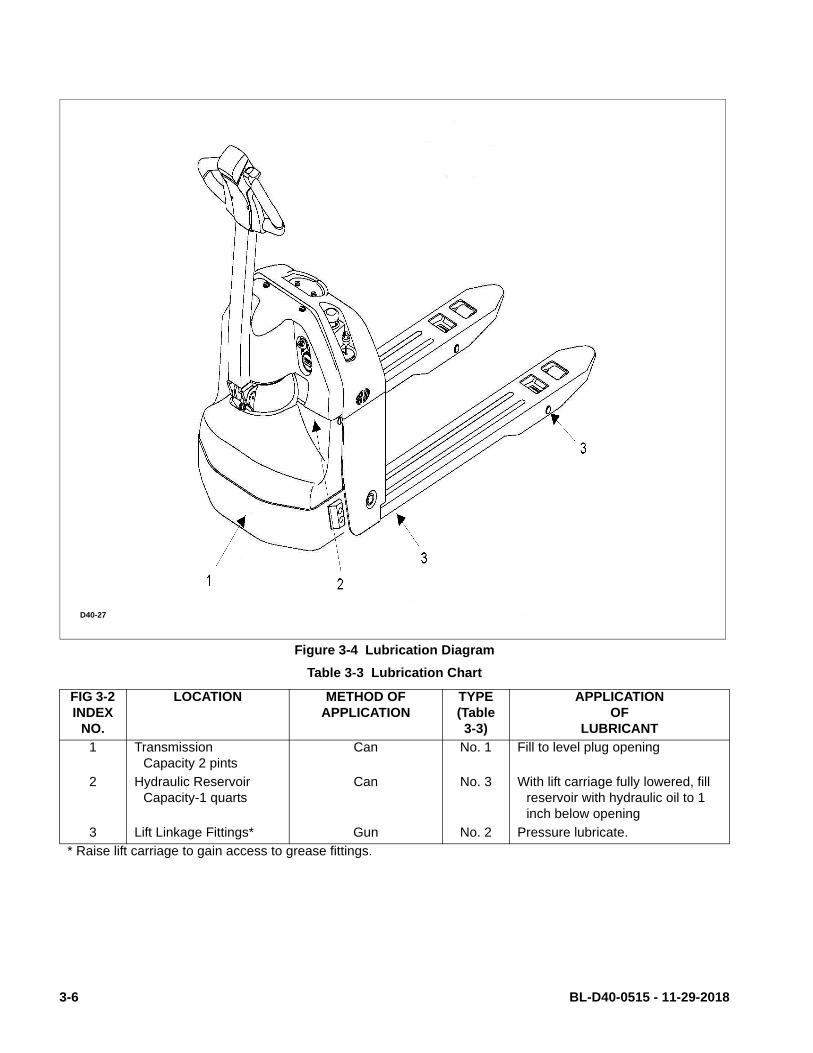
Figure 3-4 Lubrication Diagram
Table 3-3 Lubrication Chart
FIG 3-2 INDEX
NO.
LOCATION METHOD OF APPLICATION
TYPE (Table 3-3)
APPLICATION OF
LUBRICANT
1 TransmissionCapacity 2 pints
Can No. 1 Fill to level plug opening
2 Hydraulic ReservoirCapacity-1 quarts
Can No. 3 With lift carriage fully lowered, fill reservoir with hydraulic oil to 1 inch below opening
3 Lift Linkage Fittings* Gun No. 2 Pressure lubricate.
* Raise lift carriage to gain access to grease fittings.
D40-27
3-6 BL-D40-0515 - 11-29-2018

SECTION 4TROUBLESHOOTING
4-1. GENERAL
Use Table 4-1 as a guide to determine possiblecauses of trouble. The table is divided into five maincategories: Truck and Hydraulic System Will Not Oper-
ate: Truck Does Not Operate Forward or Reverse:Trouble With Braking: Trouble With Lifting Or Lower-ing, and Miscellaneous malfunctions.
Table 4-1 Troubleshooting Chart
MALFUNCTION PROBABLE CAUSE CORRECTIVE ACTION
TRUCK AND HYDRAULIC SYSTEM WILL NOT OPER-ATE
Truck will not travel nor will lift sys-tem operate.
a. Fuse (12, Figure 12-21) blown. Check fuse and replace if necessary.
b. Battery dead or disconnected. Check battery connections and check battery voltage.
c. Keyswitch (20, Figure 12-22) defective.
Bypass keyswitch to determine if it is malfunctioning.
d. Defective wiring. Check for open circuit. Repair as required.
TRUCK DOES NOT OPERATE FORWARD OR REVERSE
Truck does not travel forward or reverse. All other functions operate normally.
a. Check all wiring. A loose con-nection may be the cause of malfunction.
Tighten all loose connections before further troubleshooting.
b. Defective deadman switch (16, Figure 12-1).
Check and replace switch if defective.
c. Defective controller (18, Figure 12-21).
Check for proper operation and replace if necessary.
d. Defective potentiometer (21, Figure 12-2).
Check and replace potentiometer if defective.
Truck travels forward but not in reverse.
Defective potentiometer (21, Fig-ure 12-2) in control head.
Check and replace potentiometer if defective.
Truck travels reverse but not in forward.
Defective potentiometer (21, Fig-ure 12-2) in control head.
Check and replace potentiometer if defective.
Truck travels forward and in reverse at lower speeds; will not travel at high speed.
Defective potentiometer (21, Fig-ure 12-2) in control head.
Check and replace potentiometer if defective.
TROUBLE WITH BRAKINGTruck does not slow with brake, or
brake does not engage.
a. Defective deadman switch (16, Figure 12-1).
Check deadman switch for continuity. If none found when the control arm is in the brake position, replace switch.
b. Defective electric brake (2, Fig-ure 12-5).
Replace brake.
Brake will not release. a. Brake temperature above 281F (140 C).
Allow to cool.
b. Open brake circuitry or wiring. Make voltage checks.
BL-D40-0515 - 11-29-2018 4-1

Table 4-1 Troubleshooting Chart - Continued
MALFUNCTION PROBABLE CAUSE CORRECTIVE ACTION
TROUBLE WITH BRAKING - Continued
Brake drags. Defective electric brake (2, Figure 12-5).
Replace.
Brake grabs. Defective electric brake (2, Figure 12-5).
Replace.
Abnormal noise and chatter when brake is applied.
Defective electric brake (2, Figure 12-5).
Replace.
TROUBLE WITH LIFTING OR LOWERING
.
Oil sprays or flows from the top of the lift cylinder.
Defective packing in lift cylinder Repair lift cylinder.
Squealing sounds when lifting forks.
a. Oil level too low. Identify oil leak.
b. Lift linkage binding. Apply grease.
Forks do not lift to top. Oil level too low. Add oil to reservoir.
Weak, slow or uneven action of hydraulic system.
a. Defective pump or relief valve. Check pressure. Adjust as necessary.
b. Worn lift cylinder. Replace cylinder.
c. Load larger than capacity. Refer to I.D.plate for capacity.
d. Defective lift motor solenoid. Replace solenoid (4, Figure 12-16) on electrical panel.
e. Battery charge low. Charge battery.
Forks do not lift, pump motor does not run.
a. Battery is dead or discon-nected.
Check and recharge if required.
b. Defective wiring. Check and repair as required.
c. Defect in electrical system for operating pump motor.
Check lift switch in control head, as well as the solenoid.
Forks do not lift, motor runs. Defect in hydraulic system. Check the oil level in the reservoir and the oil lines to the lift cylin-der, and repair as required. If normal, check the hydraulic pump, and relief valve. Repair, or adjust.
4-2 BL-D40-0515 - 11-29-2018

Table 4-1 Troubleshooting Chart - Continued
MALFUNCTION PROBABLE CAUSE CORRECTIVE ACTION
TROUBLE WITH LIFTING OR LOWERING - Continued
Forks lift, but will not go down. Defect in hydraulic system Check lowering control switch in control head and lowering sole-noid on valve assembly (17, Figure 12-16). Replace as required.
Load will not hold a. Oil bypassing internally in con-trol valve
Replace valve assembly (4, Fig-ure 12-16).
b. Worn lift cylinder or packing. Repack cylinder.
Platform does not lift to top. Pump motor runs.
a. Oil level too low. Add oil to reservoir.
b. Load larger than capacity. Refer to nameplate on side of mast for maximum load capac-ity.
c. Batteries need charging. Change batteries.
Forks creep downward under load when in a raised position.
Leak in hydraulic system, lift cylin-der or lowering valve.
Check for leaking fitting in hydrau-lic line and repair as required. Repack lift cylinder or replace valve assembly (7, Figure 12-16).
MISCELLANEOUSSteering arm does not return to
the upright position.a. Week return spring. Replace spring.
b. Binding. Check and free the binding item. Verify that the cable has not been damaged. Repair or replace as needed.
Truck moves forward when arm is pulled down.
a. Belly-button switch defective. Check for short, and repair or replace as necessary.
b. Short in control head. Check wiring and repair as required.
Steering arm jerks excessively starting or stopping the truck.
Drive wheel worn. Replace drive wheel if worn to within 3/4 inch of hub.
Drive motor is jerky. Motor internally damaged or worn. Replace motor.
BL-D40-0515 - 11-29-2018 4-3

4-2. CONTROLLER TROUBLESHOOTING
4-2.1. Zapi Handset
The Zapi Handset for use with the Zapi controllerserves multiple functions of reading diagnostic data,testing truck operation, setting options, adjustmentsand parameter changes of the controller. The ZapiHandset is available through your Big Lift LLC dealer.If you require dealer location information, contact BigLift LLC.
Remove the rubber plug from the CNC connector ofthe controller and plug in the Zapi Handset connectoras shown in Figure 4-1.
Figure 4-1 Zapi Controller
4-2.2. Fault Detection.
4-2.2.1. General
The controller provides diagnostics information toassist technicians in troubleshooting problems. Whena fault is detected, an alarm is recorded in the logbook.It has a FIFO (First Input First Output) structure thatmeans the oldest alarm is lost when the database isfull and a new alarm occurs. The logbook is composedof alarms with the following information:
• The alarm code
• The number of times that each alarm occurs consec-utively
• The Hour Meter reading (value) when the latestevent of every alarm occurred
• The invert temperature when the latest event ofevery alarm occurred.
This function permits a deeper diagnosis of problemsas the recent history can be revisited.
4-2.2.2. Logbook Access
To view the alarm logbook proceed as follows:
1. Connect the Zapi Handset, refer to paragraph 4-2.1.
2. Press the ROLL down button (1, Figure 4-2) andthe ENTER button (3) at the same time to enterthe MAIN MENU.
3. Press the ROLL down button (2) or the ROLL upbutton (1) to find the ALARMS display.
4. Press the ENTER button (3) to view the alarms.
5. Press the OUT button (6) to exit the alarms.
NOTE: Refer to bigjoesupport.com for the Zapi sup-plement containing detailed information ofalarm codes. There are two versions shown.The PDS uses the Standard version whichlists the error by: Alarm Name, Repetitions,Temperature and Hour Meter reading.
4-2.3. Testing Truck Operation.
The Zapi Handset can be used to test certain truckoperations as follows:
1. Connect the Zapi Handset, refer to paragraph 4-2.1.
2. Press the ROLL down button (1, Figure 4-2) andthe ENTER button (3) at the same time to enterthe MAIN MENU.
3. Press the ROLL down button (2) or the ROLL upbutton (1) to find the TESTER display.
4. Press the ENTER button (3) to view the tests.
5. To verify various switch functions, locate theswitch on the display and then operate that func-tion to verify operation
6. Press the OUT button (6) to exit the tests.
R6628
4-4 BL-D40-0515 - 11-29-2018

4-2.4. Settings and Adjustments
4-2.4.1. Set Options
To set options proceed as follows and refer to Table 4-2:
1. Connect the Zapi Handset, refer to paragraph 4-2.1.
2. Press the ROLL up button (1, Figure 4-2) and theSET up button (5) at the same time to enter theCONFIG MENU.
3. Press the ROLL down button (1) or the ROLL upbutton (2) to find the SET OPTIONS display.
4. Press the ENTER button (3) to view the options.
5. Press the ROLL down (2) or the ROLL up button(1) to find the option to be changed.
6. Press the SET up button (5) or the SET down but-ton (6) until the desired value setting is reached.The option is now set at the desired value.
7. Press the OUT button (4) to exit the options.
Figure 4-2 Zapi Handset
Table 4-2 Set Options
R6624
Parameter Factory Setting Description
TILLER switch HANDLE This option handles the input CNB#3 (Table 4-5). This input opens when the operator leaves the truck (released). It is connected to a Keyswitch controlled voltage when the operator is present.
SET INPUT #1 OPTION #1 (Standard Version only). This option handles the digital input CNA#15. It can be can be set as:
• OPTION #1: CNA is managed as a cutback speed input (SR#1).• OPTION #2: CNA is managed as a digital handbrake input.• OPTION #3: CNA is managed as an inching backward.The input CNA#15 (Table 4-5) can only be used as Aux Lowering
request when the MDIPRC is PRESENT.This input must be connected to a Keyswitch controlled voltage.The SR#1 becomes active when CNA#15 (Table 4-5) is open.The inching backward becomes active when the CNA#15 (Table 4-
5) is closed to a Keyswitch controlled voltage.
BL-D40-0515 - 11-29-2018 4-5

Table 4-2 Set Options - Continued
Parameter Factory Setting Description
SET INPUT #2 PRESENT It can be can be set as:• PRESENT: CNA#14 (Table 4-5) is managed as a cutback speed
input (SR#2).• OPTION #1: CNA#14 (Table 4-5) is managed as an inching back-
ward.The input CNA#14 (Table 4-5) can only be used as Aux Lifting
request when the MDIPRC is PRESENT.This input must be connected to a Keyswitch controlled voltage.The SR#2 becomes active when CNA#14 (Table 4-5) is open.The inching backward becomes active when the CNA#14 (Table 4-
5) is closed to a Keyswitch controlled voltage.
SET INPUT #4 OPTION #1 This option handles the digital input CNB#7 (Table 4-5). It can be can be set as:
• BELLY CNB#7 (Table 4-5) is managed as a Belly Switch input.• BRAKE CNB#7 (Table 4-5) is managed as service brake input.
This information can be used also to recognize when the operator is driving with a pressed pedal braking.
• EX.HYDRO: CNB#7 (Table 4-5) is managed as Exclusive Hydro.This input must be connected to a Keyswitch controlled voltage.The Belly switch active level is specified on the QUICK INV LOGIC
below.The service brake of the exclusive hydro becomes active when
CNB#7 is opened.
HOUR COUNTER RUNNING This option specifies the hour counter mode. It can be set as:• RUNNING: The counter registers travel time only.• key on: The counter registers when the keyswitch is closed.
BATTERY CHECK Level = 1 This option specifies the handling of the low battery charge detec-tion. It can be set as:
• Level 0: Nothing happens, the battery charge level is ignored.• Level 1: A BATTERY LOW alarm is raised when the battery level
is calculated being less than 10% of the full charge. A BATTERY LOW alarm inhibits the Lifting function.
• Level 2: A BATTERY LOW alarm is raised when the battery level is calculated being less than 10% of the full charge. A BATTERY LOW alarm reduces the maximum truck speed down to 24% of the full truck speed then, if the MDI-PRC is absent, inhibits the Lift-ing function.
• Level 3 Equivalent to Level 1; a BATTERY LOW alarm is raised when the battery level is calculated being less than 10% of the full charge. A BATTERY LOW alarm inhibits the Lifting function.
HYDRO KEY ON OFF ON/OFF: If this options is programmed ON the traction Inverter manages a hydraulic steering function when the keyswitch is switched ON (only if the AUX OUTPUT #1 option is programmed as HYDRO CONTACT or as WXCLUSIVE HYDRO).
STOP ON RAMP OFF Not used.
4-6 BL-D40-0515 - 11-29-2018

Table 4-2 Set Options - Continued
Parameter Factory Setting Description
AUX OUTPUT #1 BRAKE This option handles output CNA#3 (Table 4-5). It can be used as:• BRAKE: CNA#3 (Table 4-5) drives an electromechanical Brake.• HYDROCOMNT: CNA#3 (Table 4-5) drives the contractor for a
hydraulic steering function when the direction input or brake pedal input are active or a movement of the truck is detected.
• EX.HYDRO: CNA#3 (Table 4-5) drives the contractor for a hydrau-lic steering function when the exclusive hydro input is active.
• FREE: CNA#3 (Table 4-5) is not used.The current this output can sink is up to 3Adc.
PEDAL BRAKING NONE The analog input CNA#18 (Table 4-5) has one of two functions:• Pedal Braking input.• Command input for lifting/lowering proportional valves in MDI-
PRC version.To turn from the first to the second function is just enough to set
PEDAL BRAKING to HNONE.This option handles the analog input CNA#18 (Table 4-5) when
used as pedal braking input:• ANALOG: With this setting it is possible to modulate the strength
of the braking when the accelerator is released. The strength of the braking is proportional to the brake pedal potentiometer con-nected to this input. When the pedal potentiometer voltage is equal/less than the SET POT BRK MIN, the minimum release braking strength is applied (following the RELEASE BRAKING setting).When the pedal potentiometer voltage is equal/higher than the SET POT BRK MAX, the maximum release braking strength is applied (following the PEDAL BRAKING setting). In the intermedi-ate position, the electrical braking strength is a linear function between the minimum (RELEASED BRAKING) and maximum (PEDAL BRAKING) intensity. When there is also a switch con-nected to the pedal braking (i.e. SET INPUT #4 to level BRAKE), it must be closed, otherwise the release braking is stuck to the mini-mum strength disregarding the pedal potentiometer position.
• DIGITAL: No pedal potentiometer is expected. Only when both the SET INPUT #4 is Level BRAKE and the brake switch connected to CNB#4 (Table 4-5) is closed, the release electrical braking follows the PEDAL BRAKING setting (maximum strength); in all of the other conditions the release electrical braking follows the RELEASE BRAKING setting (minimum strength).
• NONE: The analog input CNA#18 (Table 4-5) is not used for the release braking modulation.
QUICK INVERSION BELLY This option specifies the quick inversion mode when the SET INPUT #4 is set BELLY. It can be set as:
• NONE: The quick inversion function is not managed (no effect when CNB#7 (Table 4-5) switches over).
• TIMED: The quick inversion function is timed.• BELLY: The quick inversion function is managed but not timed.
Table 4-2 Set Options - Continued
BL-D40-0515 - 11-29-2018 4-7

Parameter Factory Setting Description
AUX VOLTAGE #1 100% This option specifies the percentage of the keyswitch controlled voltage to be applied to the loads on CNA#1 (Table 4-5) (main contactor coil) and CNA#3 (Table 4-5) (electromechanical brake). The voltage modulation is set with a PWM at 1 kHz frequency. After an initial delay of about 1 sec in which the entire keyswitch controlled voltage is applied to the loads, the PWM reduces the voltage at the loads down to the specified percentage.
PERFORMANCE OPTION #1 This option can be set • OPTION#1• OPTION#2
QUICK INV. LOGIC OPTION #1 This option specifies the active level for the Belly switch input (CNB#7)
• OPTION#1: The quick inversion is executed when CNB#7 (Table 4-5) is closed to a Keyswitch controlled voltage.
• OPTION#2: The quick inversion is executed when CNB#7 (Table 4-5) is opened from a Keyswitch controlled voltage.
MDI-PRC ABSENT This option specifies:• PRESENT: The MDI-PRC is connected to the ACO via the CAN
Bus: the handling of the Hydraulics is specified on the TRUCK TYPE setting.
• ABSENT: The MDI-PRC is not connected to the ACO: the TRUCK TYPE disappears from the SET OPTIONS function list.
MOT SET-UP LOCK OFF Not used.
4-8 BL-D40-0515 - 11-29-2018

4-2.4.2. Adjustments
To change an adjustment proceed as follows and referto Table 4-3:
1. Connect the Zapi Handset, refer to paragraph 4-2.1.
2. Press the ROLL up button (1, Figure 4-3) and theSET up button (5) at the same time to enter theCONFIG MENU.
3. Press the ROLL down button (1) or the ROLL upbutton (2) to find the ADJUSTMENTS display.
4. Press the ENTER button (3) to view the adjust-ments.
5. Press the ROLL down button (2) or the ROLL upbutton (1) to find the adjustment to be changed.
6. Press the SET up button (5) or the SET down but-ton (6) until the desired value setting is reached.The adjustment is now set at the desired value.
7. Press the OUT button (4) to exit the adjustments.
Figure 4-3 Zapi Handset
Table 4-3 Adjustments
R6624
Parameter Factory Setting Description
SET POT BRK MIN 0.5 V This setting records the minimum value of braking pedal potentiom-eter when the braking pedal switch is closed; the procedure is similar to the PROGRAM VACC function. This procedure must be carried out only if the PEDAL BRAKING option is programmed as ANALOG. No adjustment is necessary when PEDAL BRAKING options is programmed as NONE.
SET POT BRK MAX 4.5 V This setting records the maximum value of braking pedal potenti-ometer when the braking pedal is fully pressed; the procedure is similar to the PROGRAM VACC function. This procedure must be carried out only if the PEDAL BRAKING option is programmed as ANALOG. No adjustment is necessary when PEDAL BRAKING options is programmed as NONE.
SET BATTERY TYPE 24V Selects the nominal battery voltage.
ADJUST BATTERY XX V Do not modify - Factory adjusted (Fine adjustment of the battery voltage measured by the controller.)
THROTTLE 0 ZONE 9% Establishes a deadband in the accelerator input curve.
Table 4-3 Adjustments - Continued
BL-D40-0515 - 11-29-2018 4-9

Figure 4-4 Throttle Regulation
Parameter Factory Setting Description
THROTTLE X POINT 45% This parameter together with the THROTTLE Y POINT, changes the characteristic of the accelerator input curve: when the acceler-ator is de-pressed to X point percent, the corresponding truck speed is Y point percent of the Maximum truck speed. The rela-tionship between the accelerator position and the truck speed is linear between the THROTTLE 0 ZONE and the X point and also between the X point and the maximum accelerator position but with two different slopes (Figure 4-4).
THROTTLE Y POINT 68% This parameter together with the THROTTLE X POINT, changes the characteristic of the accelerator input curve: when the acceler-ator is de-pressed to X point percent, the corresponding truck speed is Y point percent of the Maximum truck speed. The rela-tionship between the accelerator position and the truck speed is linear between the THROTTLE 0 ZONE and the X point and also between the X point and the maximum accelerator position but with two different slopes (Figure 4-4).
ADJUSTMENT #01 LEVEL = 5 Adjust the upper level of the battery charge table (Level 0 to 9).
ADJUSTMENT #02 LEVEL = 5 Adjust the lower level of the battery charge table (Level 0 to 9).
LOAD HM FROM MDI
OFF When set On, the Hourmeter of the Controller is transferred and recorded on the Hourmeter of the Standard MDI (connected on the Serial Link).
CHECK UP DONE OFF Turn it On when asked Maintenance service has been executed to cancel the CHECK UP NEEDED warning.
CHECK UP TYPE NONE It specifies the handling of the CHECK UP NEEDED warning:• NONE: No CHECK UP NEEDED warning.• OPTION#1: CHECK UP NEEDED warning on the handset and
MDIPRC after 300 hours.• OPTION#2: Equal to OPTION#1 but Speed reduction after 340
hours.• OPTION#3: Equal to OPTION#2 but the truck definitively stops
after 380 hours.
R6642
4-10 BL-D40-0515 - 11-29-2018

4-2.4.3. Parameter Change
To change a parameter proceed as follows and refer toTable 4-4:
1. Connect the Zapi Handset, refer to paragraph 4-2.1.
2. Press the ROLL down button (1, Figure 4-5) andthe ENTER button (3) at the same time to enterthe MAIN MENU.
3. Press the ROLL down button (1) or the ROLL upbutton (2) to find the PARAMETER CHANGE dis-play.
4. Press the ENTER button (3) to view the parame-ters.
5. Press the ROLL down button (2) or the ROLL upbutton (1) to find the parameter to be changed.
6. Press the SET up button (5) or the SET down but-ton (6) until the desired value setting is reached.The parameter is now set at the desired value.
7. Press the OUT button (4) to exit the parameters.
Figure 4-5 Zapi Handset
Table 4-4 Parameter Adjustments
R6624
Parameter Factory Setting Description
ACCELER. DELAY LEVEL = 8 Level 0 to 9. It determines the acceleration ramp. At Level 9 the truck takes a long time to accelerate.
RELEASE BRAKING LEVEL = 5 Level 0 to 9. It controls the deceleration ramp when the travel request is released. At Level 9 the truck brakes abruptly.
INVERS. BRAKING LEVEL = 4 Level 0 to 9. It controls the deceleration ramp when the direction switch is inverted during travel. At Level 9 the truck brakes abruptly.
PEDAL BRAKING LEVEL = 9 Level 0 to 9. It controls the deceleration ramp when the travel request is released and the brake pedal switch is pressed to its maximum. At Level 9 the truck brakes abruptly.
SPEED LIMIT BRK LEVEL = 1 Level 0 to 9. It controls the deceleration ramp when the accelerator has turned down but not completely released. At Level 9 the truck decelerates abruptly.
BRAKE CUTBACK LEVEL = 5 Level 0 to 9. It controls the deceleration ramp when the a speed reduction input becomes active and the motor slows down. At Level 9 the truck decelerates abruptly.
MAX SPEED FORW 100 Hz Typically from 90 Hz to 160 Hz. It determines the maximum speed in forward direction.
MAX SPEED BACK 100 Hz Typically from 90 Hz to 160 Hz. It determines the maximum speed in backward direction.
BL-D40-0515 - 11-29-2018 4-11

Table 4-4 Parameter Adjustments - Continued
Parameter Factory Setting Description
CUTBACK SPEED 100% Typically from 10% to 100%. It determines the percentage of the max speed applied when the cutback switch 1 (SR#1 on CNA#15 (Table 4-5) is active. When set to 100% the speed reduction is ineffective.
CUTBACK SPEED 2 37% Typically from 10% to 100%. It determines the percentage of the max speed applied when the cutback switch 2 (SR#2 on CNA#14 (Table 4-5) is active. When set to 100% the speed reduction is ineffective.
HS CUTBACK 100% Typically from 10% to 100%. It determine the percentage of the max speed applied when the Hard & Soft function (H&S switch on CNB#4 (Table 4-5) is active. When set to 100% the speed reduc-tion is ineffective.
FREQUENCY CREEP
5.00 Hz Hz value. This is the minimum speed applied when the forward or reverse switch is closed, but the accelerator at its minimum. In the ACO sense Coils this setting is higher equal than 5 Hz.
RPM CREEP 100% A Percentage value. Set to 100% and not Used.
MAXIMUM CURRENT
96% It specifies the percentage of the absolute current (150A) at which the current will be limited. Normally MAXIMUM CURRENT is 100%. DO NOT CHANGE.
INCHING SPEED 0 Hz Hz value. It determines the speed when the “Inching function” is active.
INCHING TIME LEVEL = 0 Level 0 to 9. It determines the duration time when the “Inching func-tion” is active.
AUXILIARY TIME 1 Time units value (seconds). For the encoder version, it determines the time duration (in seconds) in which the the frequency was arrived to zero.
ANTIROLLBACK 80% A Percentage of the Maximum Current. This setting increases the phase current when low frequency during starting operation. It is used to push up, in feedforward way, the torque when it is not possible to control the flux, in feedback way, because of the lowfrequency.
4-12 BL-D40-0515 - 11-29-2018

Figure 4-6 Zapi Controller Connections
Table 4-5 Zapi Controller Connector Pins
CNA Connector
PIN ABBREVATION DESCRIPTION
CNA#1 NMC Negative of main contactor coil.
CNA#2 PMC Positive of main contactor coil.
CNA#3 NEB Output for driving the electromechanical brake coil; drives the load to -Batt. Maximum current: 3 A.
CNA#4 NPC Negative of pump contactor soil.
CNA#5 PPC/PEV Positive of pump contactor coil and lowering electrovalve coil.
CNA#6 NEV Negative of the lowering electrovalve coil.
CNA#7 CAN LOW Low level CAN-BUS voltage I/O.
CNA#8 -BAT -Bat.
CNA#9 ENC+ Encoder Positive Supply (+5 or +12 Vdc)
CNA#10 ENC- Encoder Negative Supply (GND to minus battery)
CNA#11 HM(+B) Output for driving an hourmeter; when the hourmeter is active this output provides a +Batt signal; 3 maximum current.
Table 4-5 Zapi Controller Connector Pins - Continued
R6628
BL-D40-0515 - 11-29-2018 4-13

CNA Connector - Continued
PIN ABBREVATION DESCRIPTION
CNA#12 -BATT -Batt.
CNA#13 MOT TH Motor thermal sensor input. The internal pull-up is a fixed 2mA (Max 5V) source current.
CNA#14 SR2 Speed reduction 2 input. Active low (switch opened).
CNA#15 SR1 Speed reduction 1 input. Active low (switch opened).
CNA#16 +12V This output provides a +12V signal for the MDI PRC, it present; mA maximum current.
CNA#17 CAN HIGH High level CAN-BUS voltage I/O.
CNA#18 CPOTB Brake potentiometer wiper.
CNA#19 ENC A Encoder Channel A.
CNA#20 ENC B Encoder Channel B.
CNB Connector
CONNECTOR PIN
ABBREVATION DESCRIPTION
CNB#1 KEY SW Connected to the power supply through a microswitch (KEY) with a 6.3-10 A fuse in series (this could be mounted on the AC-0 cover).
CNB#2 CM Common for FW/BW/SR1/SR2/TILLER/H&S/BELLY/LIFTING/LOWERING microswitches. This connection supplies a keyswitch voltage level.
CNB#3 TILLER SW Tiller request input. Must be connected to the tiller microswitch, active high.
CNB#4 H&S SW Hard & Soft request input. Must be connected to the Hard & Soft microswitch, active high.
CNB#5 BACKWARD SW Backward direction request input. Must be connected to the back-ward direction microswitch, active high.
CNB#6 FORWARD SW Forward direction request input. Must be connected to the forward direction microswitch, active high.
CNB#7 BELLY SW Quick inversion function input; must be connected to the Belly microswitch; it is active high.
CNB#8 LOWERING SW Lowering request input, active high.
CNB#9 LIFTING SW Lifting request input, active high.
CNB#10 CPOT Lifting request input, active high.
CNB#11 NPOT Negative of accelerator unit, tested for wire disconnection diagnosis.
CNB#12 PPOT Potentiometer positive: 10V output; keep load >1k
Table 4-5 Zapi Controller Connector Pins - Continued
4-14 BL-D40-0515 - 11-29-2018

CNC Connector
CONNECTOR PIN
ABBREVATION DESCRIPTION
CNC#1 PCLRXD Positive serial reception.
CNC#2 NCLRXD Negative serial reception.
CNC#3 PCLTXD Positive serial transmission.
CNC#4 NCLTXD Negative serial transmission.
CNC#5 GND Negative console power supply.
CNC#6 +12V Positive console power supply.
CNC#7 FLASH Must be connected to C8 for the Flash memory programming (if used).
CNC#8 FLASH Must be connected to C7 for the Flash memory programming (If used).
BL-D40-0515 - 11-29-2018 4-15

NOTES
4-16 BL-D40-0515 - 11-29-2018

SECTION 5STEERING ARM, CONTROL HEAD AND COMPARTMENT
5-1. CONTROL HEAD
5-1.1. Control Head Removal
1. Turn off key switch and emergency disconnect.
2. Remove the cap assembly as described in para-graph 5-1.3.
3. Disconnect wire harness assembly from potenti-ometer.
Figure 5-1 Steering Arm
DK_0001
BL-D40-0515 - 11-29-2018 5-1

4. Disconnect wire harness assembly from emer-gency reverse switch.
5. Remove two screws, two washers and two flatwashers that holds control head to the steeringarm.
WARNING: When removing the control head in thefollowing steps, be sure to hold it in placeuntil the control harness is disconnected.
6. Remove the remaining two screws, two washersand two flat washers that holds control head tothe steering arm.
7. Remove the control head and handle.
Figure 5-2 Control Head
DK_0002
5-2 BL-D40-0515 - 11-29-2018
5-1.2. Control Head Installation
1. Secure control head and handle with the screws,washers and flat washers that holds the controlhead to the steering arm.
2. Reconnect the wire harness assembly to emer-gency reverse switch.
3. Reconnect the wire harness assembly to potenti-ometer.
4. Install the cap assembly as described in para-graph 5-1.4.
5. Turn on key switch and emergency disconnect.
5-1.3. Cap Assembly Removal.
1. Turn off key switch and emergency disconnect.
2. Remove four screws and lift up cap assembly.
3. Disconnect harness from the wire harness assem-bly and remove cap assembly.
5-1.4. Cap Assembly Installation.
1. Hold cap assembly in place and connect wire har-ness assembly to harness.
2. Position cap assembly on control head and securewith four screws.
1. Turn on key switch and emergency disconnect.
5-1.5. Speed Potentiometer Replacement.
1. Remove the cap assembly as described in para-graph 5-1.3.
2. Disconnect wire harness assembly from potenti-ometer.
3. Remove screw, washer and control knob frompotentiometer.
4. Remove screw, washer and control knob from otherside of potentiometer.
5. Remove screws, lock washers and flat washersthat secure the potentiometer and switch assem-bly to bracket. Remove the potentiometer
6. Position new potentiometer and switch assemblyin bracket and secure with screws, lock washersand flat washers.
7. Install control knob on potentiometer and securewith screw and washer.
8. Install control knob on the other side of potentiom-eter and secure with screw and washer.
9. Reconnect wire harness assembly to potentiome-ter.
10. Install the cap assembly as described in para-graph 5-1.4.
5-1.6. Belly-Button Switch Replacement.
1. Remove the cap assembly as described in para-graph 5-1.3.
2. Disconnect wire harness assembly from emer-gency disconnect switch.
3. Remove screws, lock washers and flat washersthat secure the potentiometer and switch assem-bly to bracket. Remove the potentiometer andemergency disconnect switch.
4. Remove pin, bracket, and spring from button.
5. Remove two pins and switch assembly frombracket.
6. Position the new switch assembly in bracket andsecure with two pins.
7. Position bracket and springs in button and installpin.
8. Position potentiometer and switch assembly inbracket and secure with screws, lock washersand flat washers.
9. Reconnect wire harness assembly to emergencyreverse switch.
10. Install the cap assembly as described in para-graph 5-1.4.
BL-D40-0515 - 11-29-2018 5-3
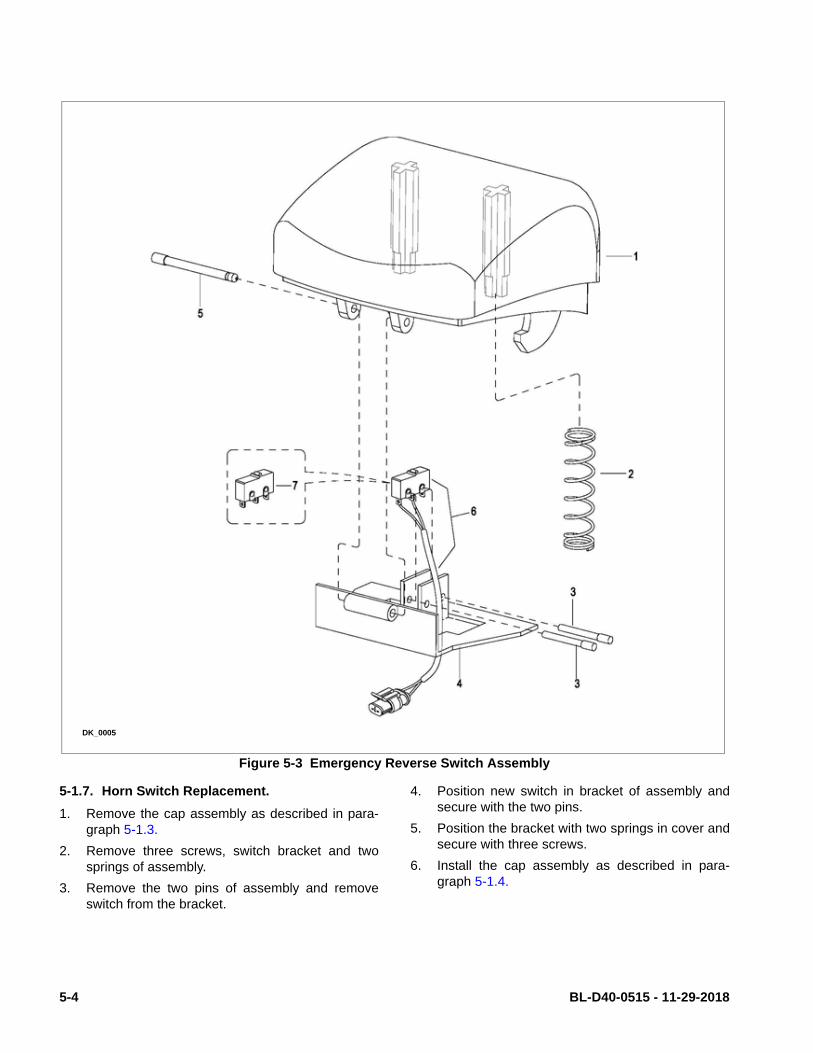
Figure 5-3 Emergency Reverse Switch Assembly
5-1.7. Horn Switch Replacement.
1. Remove the cap assembly as described in para-graph 5-1.3.
2. Remove three screws, switch bracket and twosprings of assembly.
3. Remove the two pins of assembly and removeswitch from the bracket.
4. Position new switch in bracket of assembly andsecure with the two pins.
5. Position the bracket with two springs in cover andsecure with three screws.
6. Install the cap assembly as described in para-graph 5-1.4.
DK_0005
5-4 BL-D40-0515 - 11-29-2018

Figure 5-4 Cap Assembly
5-1.8. Lift and Lower Switch Replacement.
1. Remove the cap assembly as described in para-graph 5-1.3.
2. Remove switch assembly from the cap.
3. Remove pin securing buttons to the bracket andremove the buttons.
4. Remove two pins, two switches and four springsfrom bracket.
5. Position switches and four springs in bracket andsecure with two pins.
6. Position switch assembly in cover and secure withpin.
7. Install the cap assembly as described in para-graph 5-1.4.
DK_0003
BL-D40-0515 - 11-29-2018 5-5
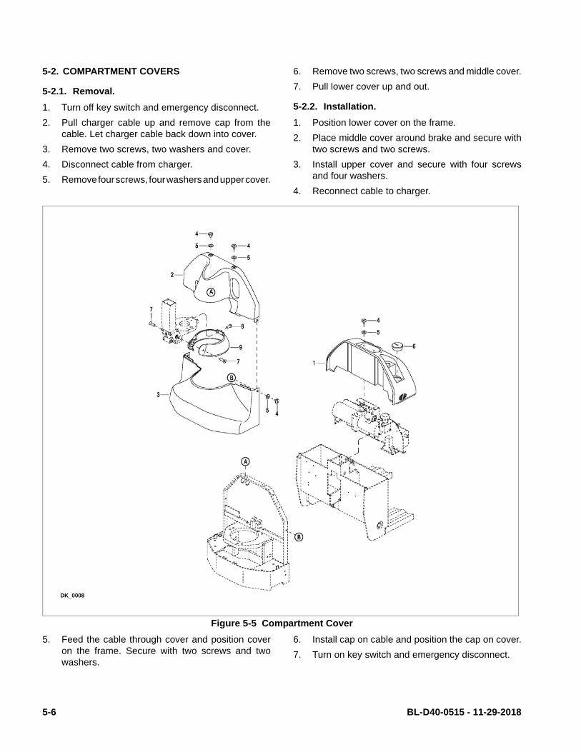
5-2. COMPARTMENT COVERS
5-2.1. Removal.
1. Turn off key switch and emergency disconnect.
2. Pull charger cable up and remove cap from thecable. Let charger cable back down into cover.
3. Remove two screws, two washers and cover.
4. Disconnect cable from charger.
5. Remove four screws, four washers and upper cover.
6. Remove two screws, two screws and middle cover.
7. Pull lower cover up and out.
5-2.2. Installation.
1. Position lower cover on the frame.
2. Place middle cover around brake and secure withtwo screws and two screws.
3. Install upper cover and secure with four screwsand four washers.
4. Reconnect cable to charger.
Figure 5-5 Compartment Cover
5. Feed the cable through cover and position coveron the frame. Secure with two screws and twowashers.
6. Install cap on cable and position the cap on cover.
7. Turn on key switch and emergency disconnect.
DK_0008
5-6 BL-D40-0515 - 11-29-2018
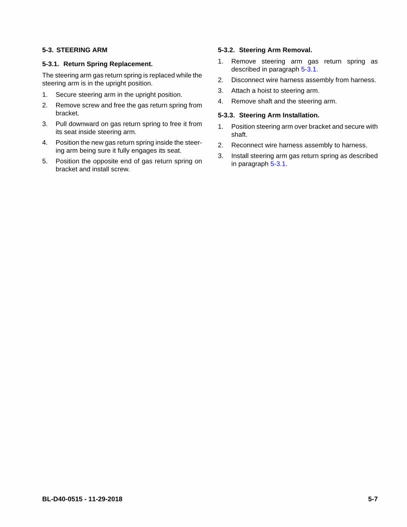
5-3. STEERING ARM
5-3.1. Return Spring Replacement.
The steering arm gas return spring is replaced while thesteering arm is in the upright position.
1. Secure steering arm in the upright position.
2. Remove screw and free the gas return spring frombracket.
3. Pull downward on gas return spring to free it fromits seat inside steering arm.
4. Position the new gas return spring inside the steer-ing arm being sure it fully engages its seat.
5. Position the opposite end of gas return spring onbracket and install screw.
5-3.2. Steering Arm Removal.
1. Remove steering arm gas return spring asdescribed in paragraph 5-3.1.
2. Disconnect wire harness assembly from harness.
3. Attach a hoist to steering arm.
4. Remove shaft and the steering arm.
5-3.3. Steering Arm Installation.
1. Position steering arm over bracket and secure withshaft.
2. Reconnect wire harness assembly to harness.
3. Install steering arm gas return spring as describedin paragraph 5-3.1.
BL-D40-0515 - 11-29-2018 5-7

5-8 BL-D40-0515 - 11-29-2018
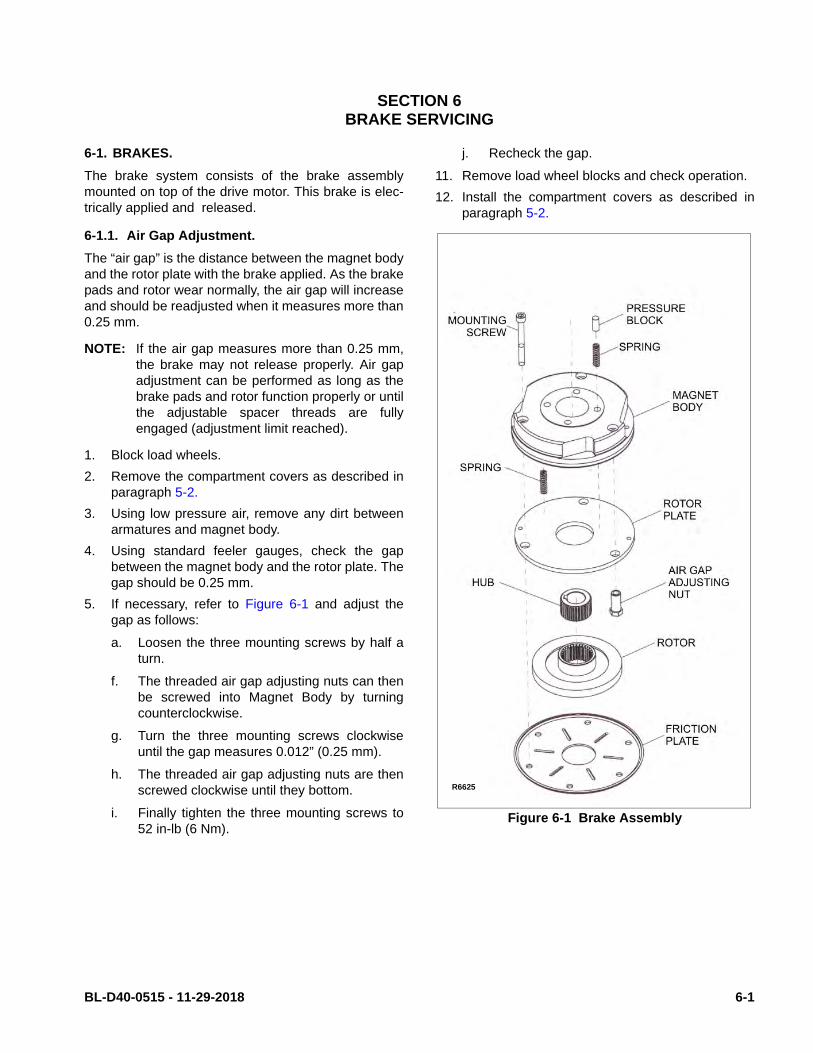
SECTION 6BRAKE SERVICING
6-1. BRAKES.
The brake system consists of the brake assemblymounted on top of the drive motor. This brake is elec-trically applied and released.
6-1.1. Air Gap Adjustment.
The “air gap” is the distance between the magnet bodyand the rotor plate with the brake applied. As the brakepads and rotor wear normally, the air gap will increaseand should be readjusted when it measures more than0.25 mm.
NOTE: If the air gap measures more than 0.25 mm,the brake may not release properly. Air gapadjustment can be performed as long as thebrake pads and rotor function properly or untilthe adjustable spacer threads are fullyengaged (adjustment limit reached).
1. Block load wheels.
2. Remove the compartment covers as described inparagraph 5-2.
3. Using low pressure air, remove any dirt betweenarmatures and magnet body.
4. Using standard feeler gauges, check the gapbetween the magnet body and the rotor plate. Thegap should be 0.25 mm.
5. If necessary, refer to Figure 6-1 and adjust thegap as follows:
a. Loosen the three mounting screws by half aturn.
f. The threaded air gap adjusting nuts can thenbe screwed into Magnet Body by turningcounterclockwise.
g. Turn the three mounting screws clockwiseuntil the gap measures 0.012” (0.25 mm).
h. The threaded air gap adjusting nuts are thenscrewed clockwise until they bottom.
i. Finally tighten the three mounting screws to52 in-lb (6 Nm).
j. Recheck the gap.
11. Remove load wheel blocks and check operation.
12. Install the compartment covers as described inparagraph 5-2.
Figure 6-1 Brake Assembly
R6625
BL-D40-0515 - 11-29-2018 6-1

6-1.2. Stopping Distance Adjustment.
The stopping distance of the truck should require mini-mal adjustment. However, this distance should bechecked with each planned maintenance.
Using an unloaded truck, run truck to its top speed onan even dry concrete surface. Move control handleinto the lower braking position. Measure length ofbraking path from the actuation point of the brakesuntil the truck has stopped. The actual length of thebraking path should be between approximately 1.5 -2.5 ft (0.5-0.7 m).
To adjust stopping distance, proceed as follows:
1. Block load wheels.
2. Remove the compartment covers as described inparagraph 5-2.
3. Rotate the adjusting nut (Figure 6-1) clockwise toSHORTEN the stopping distance or counterclock-wise to LENGTHEN the stopping distance.
4. Remove load wheel blocks and check operation.
5. Install the compartment covers as described inparagraph 5-2.
6-1.3. Brake Assembly Replacement
1. Block load wheels.
2. Remove the compartment covers as described inparagraph 5-2.
3. Disconnect electric brake from harness.
4. Remove the three mounting screws and the brake.
5. Place the new brake into position and secure withthe three mounting screws.
6. Finally tighten the three mounting screws to 52 in-lb (6 Nm).
7. Reconnect electric brake from harness.
8. Remove load wheel blocks and check operation.
9. Install the compartment covers as described inparagraph 5-2.
6-2 BL-D40-0515 - 11-29-2018

SECTION 7TRANSMISSION, DRIVE WHEEL, LOAD WHEEL
7-1. Load Wheel.
7-1.1. Removal
1. Raise forks.
1. Turn off key switch and emergency disconnect.
2. Block the drive wheel to prevent the truck fromrolling.
3. Jack up the forks to raise the load wheels off thefloor. Securely block the forks in the raised posi-tion by positioning supports under both fork tips.
NOTE: When shaft is removed, load wheel assemblywill drop free.
4. Remove pin securing shaft and remove shaft andload wheel assembly.
NOTE: Inspect the load wheel assembly. If the loadwheel is worn within 1/8" of the metal sleeve,or is cracked or damaged, replace the entireload wheel and bearing assembly. Big LiftLLC recommends that both load wheelassemblies be replaced at the same time.
This ensures level and safe operation of thelift truck.
7-1.2. Repair
1. Remove bearings from wheels.
2. Inspect bearings and replace if necessary.
3. Reassemble bearings in wheels.
7-1.3. Load Wheel Installation
1. Position load wheel assembly in wheel bracket.
2. Install shaft and secure with pin.
3. Remove blocking from under the truck.
4. Lower the forks.
5. Turn on key switch and emergency disconnect.
Figure 7-1 Wheel Assembly
DK_0012
BL-D40-0515 - 11-29-2018 7-1

7-2. Drive Wheel.
1. Turn off key switch and emergency disconnect.
2. Remove the compartment covers as described inparagraph 5-2.
3. Loosen but do not remove the five nuts.
4. Jack up the truck so the drive wheel is off theground; then securely block the truck to preventmovement.
5. Remove five nuts, five washers, and drive wheelfrom transmission.
6. Install new drive wheel in reverse order ofremoval.
7. Install the compartment covers as described inparagraph 5-2.
8. Turn on key switch and emergency disconnect.
7-3. Transmission.
1. Turn off key switch and emergency disconnect.
2. Remove the compartment covers as described inparagraph 5-2.
3. Remove the brake as described in paragraph 6-1.3.
4. Remove the steering arm as described in para-graph 5-3.2.
5. Disconnect harness from drive motor.
6. Remove drive motor as described in paragraph10-3.
7. Remove drive wheel as described in paragraph 7-2.
8. Support the transmission and remove five screws,five washers and five flat washers.
9. Slowly lower the transmission out the bottom ofthe frame.
10. Install new transmission by reversing the stepsabove.
7-2 BL-D40-0515 - 11-29-2018

Figure 7-2 Transmission Motor, Brake Mounting
DK_0006
BL-D40-0515 - 11-29-2018 7-3

7-4 BL-D40-0515 - 11-29-2018
SECTION 8ELEVATION SYSTEM SERVICING
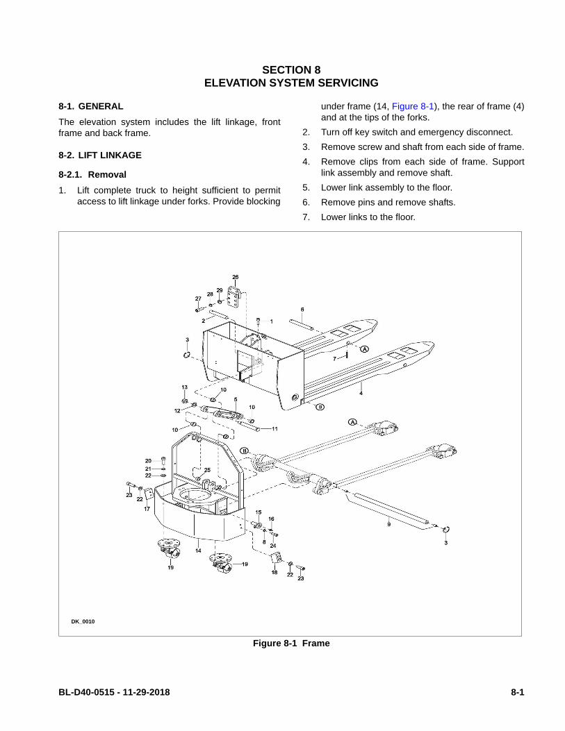
8-1. GENERAL
The elevation system includes the lift linkage, frontframe and back frame.
8-2. LIFT LINKAGE
8-2.1. Removal
1. Lift complete truck to height sufficient to permitaccess to lift linkage under forks. Provide blocking
under frame (14, Figure 8-1), the rear of frame (4)and at the tips of the forks.
2. Turn off key switch and emergency disconnect.
3. Remove screw and shaft from each side of frame.
4. Remove clips from each side of frame. Supportlink assembly and remove shaft.
5. Lower link assembly to the floor.
6. Remove pins and remove shafts.
7. Lower links to the floor.
Figure 8-1 Frame
DK_0010
BL-D40-0515 - 11-29-2018 8-1

8-2.2. Repair
1. Remove pins , shafts and load wheel from wheelbrackets.
2. Remove pins (11) and shafts. Free brackets fromtension bars.
3. Remove bushings from brackets if replacement isnecessary,
4. Remove pins and shafts from connector and freetension bars from connector.
5. Loosen nuts and remove clevises from tension bars.
6. Remove bushings from link if replacement is nec-essary.
7. Install reassemble by reversing the steps above.
8-2.3. Installation
1. Position link assembly under frame.
2. Position wheel brackets in frame and install shafts.Secure shafts with pins.
3. Position link assembly and install shafts. Secureshafts with screws,
4. Remove blocking and lower the truck to the ground.
5. Turn on key switch and emergency disconnect.
Figure 8-2 Lift Linkage Assembly
DK_0011
8-2 BL-D40-0515 - 11-29-2018

SECTION 9HYDRAULIC SYSTEM SERVICING
9-1. LINES AND FITTINGS
WARNING: When forks are raised, pressure exists inthe hydraulic system lines and fittings. Toensure release of pressure, forks mustbe fully lowered before performing anymaintenance on the hydraulic system.
NOTE: Leaking hydraulic fittings may be remedied bysimply tightening fittings. If this does not rem-edy the leak, the fittings or line must bereplaced.
1. Lower forks fully.
2. Turn off key switch and emergency disconnect.
3. Remove the compartment covers as described inparagraph 5-2.
Figure 9-1 Hydraulic System
DK_0014
BL-D40-0515 - 11-29-2018 9-1

CAUTION: Hydraulic oil can damage parts. Wipe offany oil immediately. Provide a containerunder the line or fitting before discon-necting.
4. Refer to Figure 9-1 and remove leaking line or fit-ting and replace it with a new line or fitting. Checklevel of hydraulic oil. With lift carriage fully low-ered, fill reservoir with hydraulic oil to 1 inch belowopening. Use hydraulic oil listed in Table 3-2.
5. Turn on key switch and emergency disconnect.
6. Operate the lift and lower buttons to refill the cylinder and lines with hydraulic oil.
7. Check level of hydraulic oil. Hydraulic oil must be1 inch below opening. If required, add hydraulicoil to bring to proper level. Use hydraulic oil listedin Table 3-2.
8. Install the compartment covers as described inparagraph 5-2.
9-2. HYDRAULIC AND ELECTRICAL ASSEMBLYREMOVAL
The hydraulic system and electrical system can beremoved as an assembly to provide additional clear-ance for various maintenance procedures.
WARNING: When forks are raised, pressure exists inthe hydraulic system lines and fittings. Toensure release of pressure, forks mustbe fully lowered and the batteries discon-nected before performing any mainte-nance on the hydraulic system.
9-2.1. Removal
1. Lower forks fully.
2. Turn off key switch and emergency disconnect.
3. Remove the compartment covers as described inparagraph 5-2.
4. Disconnect hose from pump and motor assembly.
5. Tag and disconnect all harnesses and cables fromelectrical components on board.
6. Support board and remove four screws , four lockwashers and four flat washers.
7. Remove board.
9-2.2. Installation
1. Position board on frame and secure with fourscrews, four lock washers and four flat washers.
2. Reconnect hose to pump and motor assembly.
3. Reconnect all harnesses and cables to electricalcomponents on board.
4. Turn on key switch and emergency disconnect.
5. Install the compartment covers as described inparagraph 5-2.
9-3. HYDRAULIC PUMP, MOTOR, AND RESER-VOIR ASSY
The hydraulic pump/motor assembly can be disas-sembled and repaired. However, a defective pump,valve or motor requires replacement of that compo-nent.
WARNING: When forks are raised, pressure exists inthe hydraulic system lines and fittings. Toensure release of pressure, forks mustbe fully lowered and the batteries discon-nected before performing any mainte-nance on the hydraulic system.
9-3.1. Removal
1. Lower forks fully.
2. Turn off key switch and emergency disconnect.
3. Remove the hydraulic and electrical assembly asdescribed in paragraph 9-2.
NOTE: The reservoir will be filled with hydraulic oil.Place a container under the pump assemblyto catch any hydraulic oil.
4. Remove two screws, lock washers and flat wash-ers and remove pump and motor.
9-3.2. Disassembly and Reassembly
1. Remove the hydraulic pump/motor assembly asdescribed in paragraph 9-3.1.
2. Refer to Figure 9-2 for disassembly and reassem-bly.
9-2 BL-D40-0515 - 11-29-2018
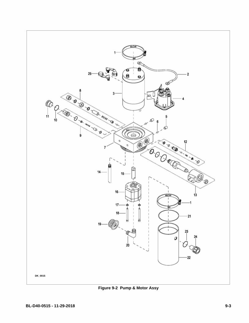
Figure 9-2 Pump & Motor Assy
DK_0015
BL-D40-0515 - 11-29-2018 9-3

9-3.3. Installation
1. Position pump and motor on board and securewith two screws, lock washers and flat washers.
2. Remove the hydraulic and electrical assembly asdescribed in paragraph 9-2.
3. Fill the hydraulic reservoir. Hydraulic oil must be 1inch below opening. If required, add hydraulic oilto bring to proper level. Use hydraulic oil listed inTable 3-2.
4. Turn off key switch and emergency disconnect.
5. Operate the lift and lower buttons to refill the cylinder and lines with hydraulic oil.
6. Check level of hydraulic oil. Hydraulic oil must be1 inch below opening. If required, add hydraulicoil to bring to proper level. Use hydraulic oil listedin Table 3-2.
7. Install the compartment cover as described inparagraph 5-2.
9-3.4. Lift Cylinder
9-3.4.1.Removal
1. Lower forks fully.
2. Turn off key switch and emergency disconnect.
3. Remove the compartment covers as described inparagraph 5-2.
4. Ensure that hydraulic pressure has been relievedfrom the lift circuit. Disconnect the hydraulic linefrom the lift cylinder.
5. Disconnect hose from cylinder.
WARNING: Frame is heavy. Use care while securingand lifting in order to prevent injury.
6. With suitable hoist, carefully raise frame slightly torelieve pressure on the cylinder.
7. Remove retaining rings and pin.
8. Remove cylinder.
9-3.4.2.Repair
1. Secure the lift cylinder in a vise, clamping lightly atthe base of the cylinder.
2. Unscrew gland nut from body.
3. Remove wiper and O-ring from gland nut.
4. Withdraw the cylinder rod from body.
5. Remove bushing, guide ring and seal ring from rod.
NOTE: If the cylinder body or piston rod are dam-aged, the entire lift cylinder must be replaced.
6. Replace guide ring, seal ring, wiper ring and O-ring.
7. Coat all parts with hydraulic oil (Table 3-2).
8. Install new guide ring, seal ring and bushing (8)on rod.
9. Insert piston rod into body.
10. Install wiper and O-ring in gland nut.
11. Install gland nut in body.
9-3.4.3.Installation
1. Position the cylinder on frame and lower theframe onto the cylinder.
2. Install pin and retaining rings.
3. Reconnect the hose to cylinder.
4. Fill the hydraulic reservoir. Hydraulic oil must be 1inch below opening. If required, add hydraulic oilto bring to proper level. Use hydraulic oil listed inTable 3-2.
5. Turn on key switch and emergency disconnect.
6. Operate the lift and lower buttons to refill the cylinder and lines with hydraulic oil.
7. Check level of hydraulic oil. Hydraulic oil must be1 inch below opening. If required, add hydraulicoil to bring to proper level. Use hydraulic oil listedin Table 3-2.
8. Install the compartment cover as described inparagraph 5-2.
9-4 BL-D40-0515 - 11-29-2018

Figure 9-3 Lift Cylinder
DK_0016
BL-D40-0515 - 11-29-2018 9-5

NOTES
9-6 BL-D40-0515 - 11-29-2018

SECTION 10ELECTRICAL COMPONENTS
10-1.ELECTRICAL CONTROL PANEL
10-1.1.Maintenance
NOTE: Erratic operation of the truck may be causedby defective controller components. Beforeremoving the electrical panel, perform trou-bleshooting procedures per SECTION 4, todetermine corrective action to be taken.
There are no user-serviceable parts inside the control-ler. No attempt should be made to open the controller.Opening the controller may damage it and will void thewarranty.
The controller is programmed at the factory specifi-cally for the truck model on which it is equipped. It isimportant to replace the controller with the correct pre-programmed unit to assure proper performance set-tings intended for that particular truck. See Figure 12-21 for the preprogrammed controller number.
It is recommended that the controller exterior becleaned periodically, and if a Zapi Handset is avail-able, this periodic cleaning provides a good opportu-nity to check the controller’s diagnostic history file. It isalso recommended that the controller’s fault detectioncircuitry be checked whenever the vehicle is serviced.
10-1.2.Cleaning
1. Turn off key switch and emergency disconnect.
2. Remove the compartment covers as described inparagraph 5-2.
3. Remove any dirt or corrosion from the bus bararea. The controller should be wiped clean with amoist rag. Allow it to dry before reconnecting thebattery.
4. Make sure the connections to the buss bars aretight. Use two well insulated wrenches for thistask in order to avoid steering the buss bars.
10-1.3.Controller Removal.
1. Turn off key switch and emergency disconnect.
2. Remove the compartment covers as described inparagraph 5-2.
3. Tag and disconnect master wire harness fromcontroller.
4. Remove four screws, lock washers and removecontroller.
10-1.4.Controller Installation.
1. Position controller and the board and secure withfour screws and lock washers.
2. Reconnect master wire harness to controller.
3. Install compartment covers as described in para-graph 5-2.
1. Turn on key switch and emergency disconnect.
10-1.5.Charger Removal.
1. Turn off key switch and emergency disconnect.
2. Remove the compartment covers as described inparagraph 5-2.
3. Tag and disconnect master wire harness fromcharger.
4. Tag and disconnect remaining two charger leadsfrom the pump motor and the fuse.
5. Remove the screws, lock washers, two straps andcharger.
10-1.6.Charger Installation.
1. Position charger on board and secure with thescrews, lock washers and two straps.
2. Reconnect the two charger leads to the pumpmotor and the fuse.
3. Reconnect master wire harness to charger.
4. Install compartment covers as described in para-graph 5-2.
5. Turn on key switch and emergency disconnect.
BL-D40-0515 - 11-29-2018 10-1

10-1.7.Emergency Disconnect Removal.
1. Turn off key switch and emergency disconnect.
2. Remove the compartment covers as described inparagraph 5-2.
3. Tag and disconnect master wire harness from emer-gency disconnect.
4. Remove the knob from the emergency disconnect
5. Remove two screws and remove emergency dis-connect from bracket.
10-1.8.Emergency Disconnect Installation.
1. Position emergency disconnect on bracket andsecure with two screws.
2. Install the knob on the emergency disconnect.
3. Reconnect master wire harness to emergencydisconnect.
4. Install compartment covers as described in para-graph 5-2.
5. Turn on key switch and emergency disconnect.
10-1.9.Contactor Removal.
1. Turn off key switch and emergency disconnect.
2. Remove the compartment covers as described inparagraph 5-2.
3. Tag and disconnect wires from contactor.
4. Remove two screws, lock washers, flat washersand remove contactor.
10-1.10.Contactor Installation.
1. Position contactor on the board and secure withtwo screws, lock washers and flat washers.
2. Reconnect wires to contactor.
3. Install compartment covers as described in para-graph 5-2.
4. Turn on key switch and emergency disconnect.
10-1.11.Fuse Removal.
1. Turn off key switch and emergency disconnect.
2. Remove the compartment covers as described inparagraph 5-2.
3. Loosen two nuts and rotate and remove fuse.
10-1.12.Fuse Installation.
1. Install fuse on the stand and secure two nuts.
2. Install compartment covers as described in para-graph 5-2.
3. Turn on key switch and emergency disconnect.
10-2 BL-D40-0515 - 11-29-2018
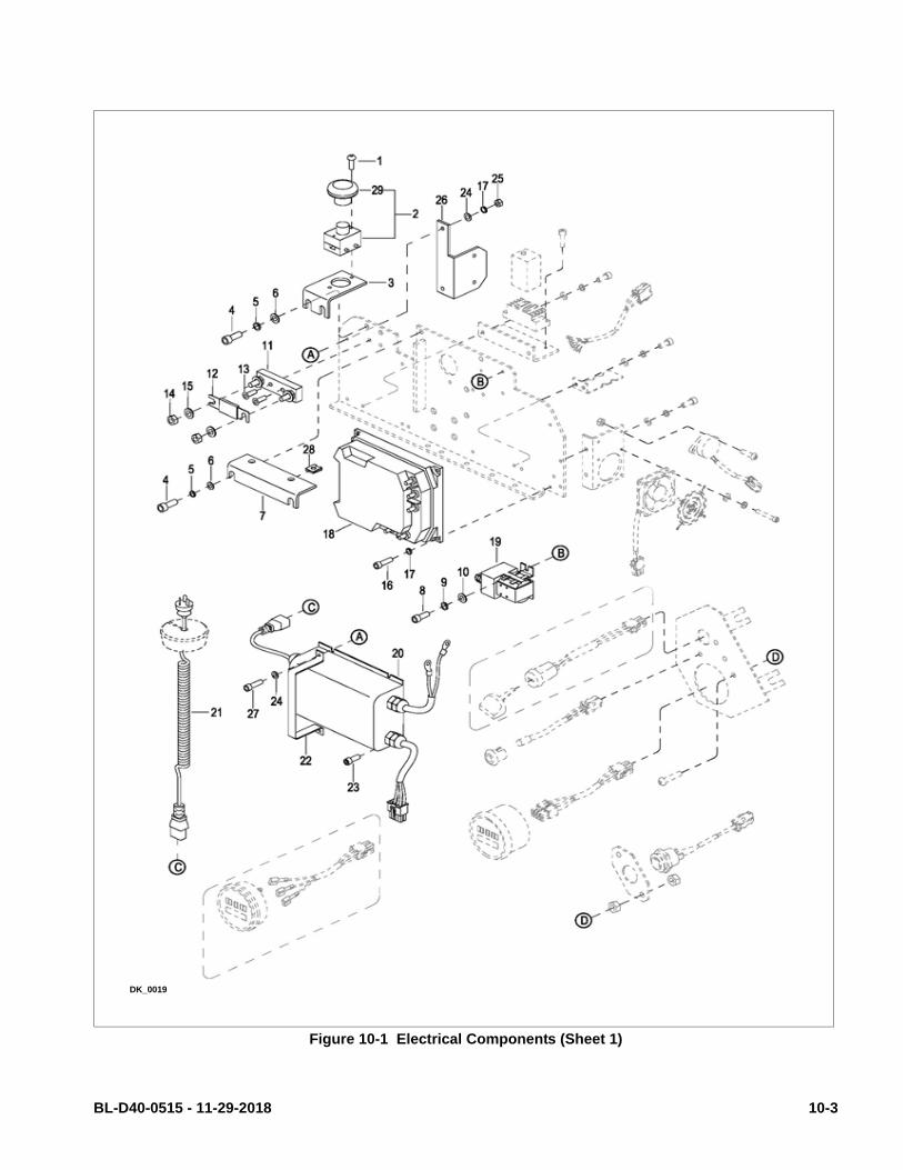
Figure 10-1 Electrical Components (Sheet 1)
DK_0019
BL-D40-0515 - 11-29-2018 10-3

10-1.13.Cooling Fan Removal.
1. Turn off key switch and emergency disconnect.
2. Remove the compartment covers as described inparagraph 5-2.
3. Tag and disconnect master wire harness fromcooling fan.
4. Remove four screws, four lock washers and fourflat washers. Remove cooling fan and guard frombracket.
10-1.14.Cooling Fan Installation.
1. Position cooling fan and guard on bracket andsecure with four screws, four lock washers andfour flat washers.
2. Reconnect master wire harness to cooling fan.
3. Install compartment covers as described in para-graph 5-2.
4. Turn on key switch and emergency disconnect.
10-1.15.Buzzer Removal.
1. Turn off key switch and emergency disconnect.
2. Remove the compartment covers as described inparagraph 5-2.
3. Tag and disconnect master wire harness frombuzzer.
4. Remove two screws and buzzer from bracket.
10-1.16.Buzzer Installation.
1. Position buzzer on bracket and secure with twoscrews.
2. Reconnect master wire harness to buzzer.
3. Install compartment covers as described in para-graph 5-2.
4. Turn on key switch and emergency disconnect.
10-1.17.Key Switch Removal.
1. Turn off key switch and emergency disconnect.
2. Remove the compartment covers as described inparagraph 5-2.
3. Tag and disconnect switch wiring harness fromkey switch.
4. Free key switch from bracket.
10-1.18.Key Switch Installation.
1. Insert key switch in bracket.
2. Reconnect switch wiring harness to key switch.
3. Install compartment covers as described in para-graph 5-2.
4. Turn on key switch and emergency disconnect.
10-1.19.Battery Indicator Removal.
1. Turn off key switch and emergency disconnect.
2. Remove the compartment covers as described inparagraph 5-2.
3. Tag and disconnect switch wiring harness frombattery indicator.
4. Remove mounting nuts and bracket and removebattery indicator from bracket.
10-1.20.Battery Indicator Installation.
1. Position battery indicator on bracket and securewith its mounting bracket and nuts.
2. Reconnect switch wiring harness to battery indi-cator.
3. Install compartment covers as described in para-graph 5-2.
4. Turn on key switch and emergency disconnect.
10-4 BL-D40-0515 - 11-29-2018

Figure 10-2 Electrical Components (Sheet 2)
DK_0020
BL-D40-0515 - 11-29-2018 10-5

10-1.21.Lift Limit Switch Removal.
1. Lower forks fully.
2. Turn off key switch and emergency disconnect.
3. Remove the compartment covers as described inparagraph 5-2.
4. Tag and disconnect master wire harness from limitswitch.
5. Remove two nuts, screws, lock washers and limitswitch from bracket.
10-1.22.Lift Limit Switch Installation.
1. Position limit switch on bracket and secure withtwo screws, lock washers and nuts.
2. Reconnect master wire harness to limit switch.
3. Install compartment covers as described in para-graph 5-2.
4. Turn on key switch and emergency disconnect.
Figure 10-3 Electric System
DK_0017
10-6 BL-D40-0515 - 11-29-2018

10-2.PUMP MOTOR.
The pump motor is replaceable but not repairable.Refer to paragraph 9-3.
10-3.DRIVE MOTOR.
The drive motor exposed surfaces should be cleanedat least once a month to assure proper cooling ofmotor. Use an air hose to blow dust off of motor sur-faces.
The drive motor is replaceable but not repairable.Refer to paragraph 7-3.
10-4.DEADMAN SWITCH
10-4.1.Replacement
1. Turn off key switch and emergency disconnect.
2. Remove the compartment covers as described inparagraph 5-2.
3. Disconnect wiring from the deadman switch.
4. Remove the two screws, lock washers andbracket from bracket.
5. Remove two screws and switch from bracket.
6. Position the new switch on bracket and securewith the two screws.
7. Position bracket on bracket and secure with twoscrews and lock washers.
8. Install compartment covers as described in para-graph 5-2.
9. Turn on key switch and emergency disconnect.
BL-D40-0515 - 11-29-2018 10-7

NOTES
10-8 BL-D40-0515 - 11-29-2018

SECTION 11OPTIONAL EQUIPMENT2
BL-D40-0515 - 11-29-2018 11-1

NOTES
11-2 BL-D40-0515 - 11-29-2018

SECTION 12ILLUSTRATED PARTS BREAKDOWN
Following is an illustrated parts breakdown of assemblies and parts associated with the D40 Lift Truck.
BL-D40-0515 - 11-29-2018 12-1
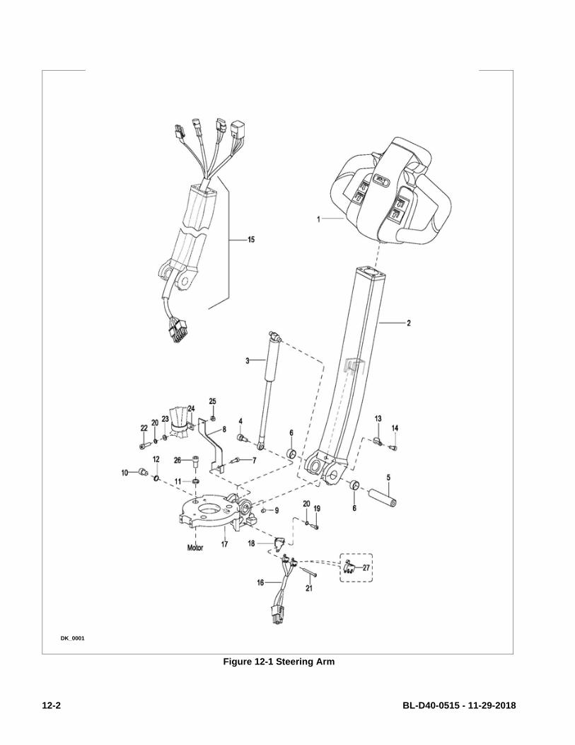
Figure 12-1 Steering Arm
DK_0001
12-2 BL-D40-0515 - 11-29-2018

STEERING ARM
Pos. Part Number DescriptionQty.
Reqd.Notes
1 1120-340000-00-B CONTROL HEAD ASSEMBLY 1Used up to Serial Number 327120792
1a 1115-340000-00-10 CONTROL HEAD ASSEMBLY 1Used from Serial Number 327120793
2 1146-330000-30 CONTROL ARM ASSEMBLY 1
3 1120-320000-00 GAS SPRING 1
4 0000-000151-00 SCREW, M8 X 25 1
5 1120-300003-00 SHAFT 1
6 0000-000011-00 BUSHING, 2015 2
7 0000-000386-00 SCREW, M6 X 20 1
8 1120-300005-00 BRACKET 1
9 0000-000429-00 SCREW, M5 X 8 1
10 0000-000030-00 SCREW, M10 X 16 1
11 0000-000159-00 LOCK WASHER, M8 3
12 0000-000063-00 LOCK WASHER, M10 1
13 0000-000490-00 HARNESS CLAMP 1
14 0000-000031-00 SCREW, M5 X 8 1
15 1118-520003-00 WIRE HARNESS 1
16 1118-520005-10 DEADMAN SWITCH ASSEMBLY 1
17 1120-300001-0A BRAKE BRACKET 1
18 1120-300006-00 SPACER 1
19 0000-000009-00 SCREW, M4 X 12 2
20 0000-000122-00 LOCK WASHER, M4 3
21 0000-000377-00 SCREW, M2 X 20 2
22 0000-000378-00 SCREW, M4 X 16 1
23 0000-000702-00 FLAT WASHER, M4 1
24 0000-000491-00 HARNESS CLAMP 1
25 0000-000139-00 NUT, M4 1
26 0000-000109-00 SCREW, M8 X 16 3
27 1220-560001-00 INCHING SWITCH 2
BL-D40-0515 - 11-29-2018 12-3

Figure 12-2 Steering Arm - Freezer
DK_0029
12-4 BL-D40-0515 - 11-29-2018

STEERING ARM - FREEZER
Pos. Part Number DescriptionQty.
Reqd.Notes
1 1280-360000-20 CONTROL POD ASSEMBLY 1
2 1120-330000-0A CONTROL HANDLE ASSEMBLY 1
3 1120-320000-00 GAS SPRING 1
4 0000-000151-00 SCREW M8×25 1
5 1120-300003-00 SHAFT 1
6 0000-000011-00 BUSHING 2015 2
7 0000-000386-00 SCREW M6×20 1
8 1120-300005-00 BRACKET 1
9 0000-000429-00 SCREW M5×8 1
10 0000-000030-00 SCREW M10×16 1
11 0000-000159-00 LOCK WASHER Ø8 10
12 0000-000063-00 LOCK WASHER Ø10 1
13 0000-000490-00 HARNESS CLAMP 1
14 0000-000031-00 SCREW M5×8 1
15 1118-520003-X0 WIRE HARNESS 1
16 1118-520005-X0 INCHING SWITCH 1
17 1120-300001-0A BRAKE BRACKET 1
18 1120-500002-LK PLATE 1
19 0000-000378-00 SCREW M4×16 2
20 0000-000122-00 LOCK WASHER Ø4 1
21 1120-520005-LK HEATER BAND 1
22 0000-000378-00 SCREW M4×16 1
23 0000-000702-00 FLAT WASHER Ø4 1
24 0000-000491-00 HARNESS CLAMP 1
25 0000-000139-00 NUT M4 1
26 0000-000109-00 SCREW M8×16 3
27 2333-320000-10 CONTROL POD BRACKET 1
28 0000-000321-00 SCREW M8×20 3
29 0000-000176-00 FLAT WASHER Ø8 7
30 0000-000322-00 SCREW M8×25 4
31 0000-001329-10 SCREW M3×16 1
BL-D40-0515 - 11-29-2018 12-5

Figure 12-3 Control Head - Used up to Serial Number 327120792
DK_0002
12-6 BL-D40-0515 - 11-29-2018

CONTROL HEAD - Used up to Serial Number 327120792
Pos. Part Number DescriptionQty.
Reqd.Notes
1 1120-342000-00-B CAP ASSEMBLY 1
2 1120-340005-00 CONTROL KNOB (R) 1
3 0000-000038-00 LOCK WASHER Ø3 2
4 0000-000037-00 SCREW M3×12 2
5 0000-000004-00 SCREW M5×12 2
6 0000-000206-00 LOCK WASHER Ø5 4
7 0000-000390-00 FLAT WASHER Ø5 4
8 0000-000088-00 SCREW M4×8 2
9 0000-000122-00 LOCK WASHER Ø4 2
10 0000-000702-00 FLAT WASHER Ø4 2
11 0000-000322-00 SCREW M8×25 2
12 0000-000159-00 LOCK WASHER Ø8 2
13 0000-000176-00 FLAT WASHER Ø8 2
14 1120-340003-00 CONTROL KNOB (L) 1
15 1120-343000-00-B REVERSING SWITCH ASSEMBLY 1
16 0000-000004-00 SCREW M5×12 2
17 0000-000035-00 SCREW M5×20 4
18 1120-340002-00 COVER 1
19 1120-341000-00 GRIPE 1
20 1120-340001-00 POD 1
21 1220-520008-0C ACCELERATOR ASSEMBLY 1
22 0000-000010-00 SCREW M5×6 1
BL-D40-0515 - 11-29-2018 12-7
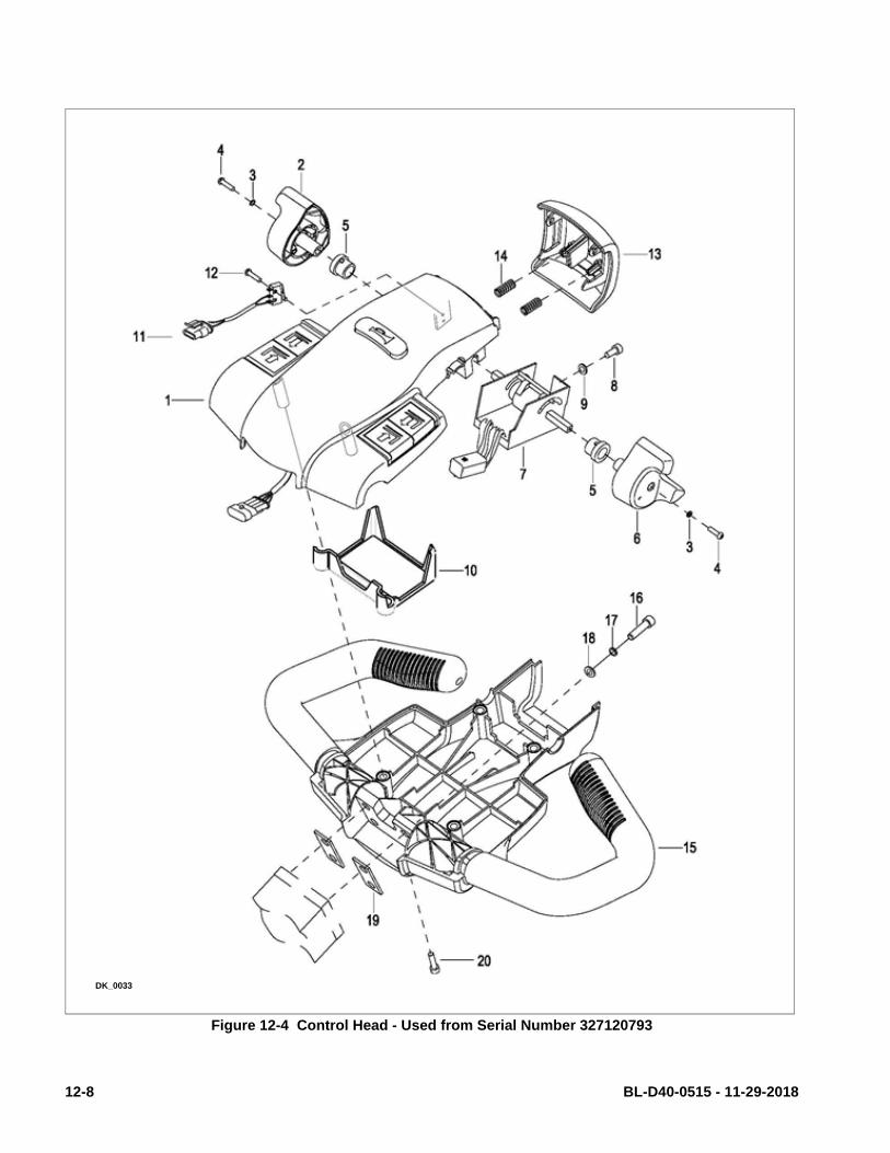
Figure 12-4 Control Head - Used from Serial Number 327120793
DK_0033
12-8 BL-D40-0515 - 11-29-2018

Control Head - Used from Serial Number 327120793
Pos. Part Number DescriptionQty.
Reqd.Notes
1 1115-341000-00-10 CAP ASSEMBLY 1
2 1115-340005-00 CONTROL KNOB (R) 1
3 0000-000038-00 LOCK WASHER Ø3 2
4 1115-340006-00 BUSHING 2
5 0000-000004-00 SCREW M3×12 2
6 1115-340004-00 CONTROL KNOB (L) 1
7 1220-520008-0C ACCELERATOR ASSEMBLY 1
8 0000-000323-00 SCREW M5×16 1
9 0000-000390-00 FLATWASHER Ø5 1
10 1115-340007-00 WIRE HARNESS COVER 1
11 1120-520009-00 REVERSING SWITCH WIRE 1
12 0000-000989-00 SCREW M2×12 2
13 1115-340003-00 COVER 1
14 1121-310004-00 SPRING 2
15 1115-340002-00 COVER 1
16 0000-000322-00 SCREW M8×25 4
17 0000-000159-00 LOCKWASHER Ø8 4
18 0000-000176-00 FLATWASHER Ø8 4
19 1115-340001-00 WASHER 2
20 0000-000035-00 SCREW M5×20 4
BL-D40-0515 - 11-29-2018 12-9

Figure 12-5 Cap Assembly
DK_0003
12-10 BL-D40-0515 - 11-29-2018

CAP ASSEMBLY
Pos. Part Number DescriptionQty.
Reqd.Notes
1 1120-342001-00 UPPER COVER 1Used up to Serial Number 327120792
1a 1115-341001-00 UPPER COVER 1Used from Serial Number 327120793
2 1120-342203-00 BUTTON FOR LIFTING (R) 1
3 1120-342202-00 BUTTON FOR LOWERING (R) 1
4 1120-342102-00 SPRING 8
5 1120-342201-00 BUTTON BRACKET (R) 1
6 1120-342105-00 PIN 6
7 1120-342104-00 BUTTON FOR LIFTING (L) 1
8 1120-342103-00 BUTTON FOR LOWERING (L) 1
9 1120-342101-00 BUTTON BRACKET (L) 1
10 1120-342300-00 HORN BUTTON ASSEMBLY 1
11 0000-000039-00 SCREW ST3.5×9.5 6
12 0000-000490-00 HARNESS CLAMP 3
13 1120-342200-00 LIFT AND LOWER BOX (R) ASSEMBLY 1
14 1120-342100-00 LIFT AND LOWER BOX (L) ASSEMBLY 1
15 1220-520006-0C BUTTONS ASSEMBLY 1
16 1220-560002-00 INCHING SWITCH II 5
17 1120-342002-00 HORN BUTTON 1
18 1120-342005-00 PIN 2
19 1120-342003-00 SPRING 2
20 1120-342004-00 BUTTON BRACKET 1
BL-D40-0515 - 11-29-2018 12-11

Figure 12-5 Control Head - Freezer
DK_0027
12-12 BL-D40-0515 - 11-29-2018

CONTROL HEAD - FREEZER
Pos. Part Number DescriptionQty.
Reqd.Notes
1 2333-340001-00 COVER 1
2 2333-340002-00 CAP 1
3 2333-340003-00 CONTROL KNOB RIGHT SIDE 1
4 2333-340004-00 CONTROL KNOB LEFT SIDE 1
5 2333-340005-00 HORN BUTTON 1
6 2333-340006-00 BUTTON REVERSER COVER 1
7 2333-340015-00 LIFT / LOWER BUTTON 2
8 2333-340013-00 SCREW M5×30 2
9 2333-340014-00 SCREW M5×55 2
10 2333-520004-10 REVERSING SWITCH WIRE 1
11 2333-520003-10 ACCELERATOR ASSEMBLY 1
12 1280-360001-20 BUTTONS ASSEMBLY 1
13 2333-340017-00 CLAMP 4
14 2333-340009-00 MOUNTING SEAT 2
15 2333-340012-00 SCREW ST2.9×9.5 2
16 2333-340010-00 SPRING 1
17 0000-000037-00 SCREW M3×12 2
18 0000-000038-00 LOCK WASHER Ø3 2
19 2333-340018-00 BRACKET 1
20 2333-340019-00 SCREW M3×10 1
21 2333-340020-00 COVER 4
22 2333-340022-00 COVER 1
23 2333-340023-00 BUTTON 1
24 2333-340024-00 SCREW M5×12 2
25 2333-340025-00 SCREW ST2.9×20 2
26 2333-340026-00 BUSHING 2
27 2333-340027-00 BUSHING 2
BL-D40-0515 - 11-29-2018 12-13

Figure 12-6 Emergency Reverse Switch Assembly - Used up to Serial Number 327120792
DK_0005
12-14 BL-D40-0515 - 11-29-2018

EMERGENCY REVERSE SWITCH ASSEMBLY - Used up to Serial Number 327120792
Pos. Part Number DescriptionQty.
Reqd.Notes
1 1120-343002-00 EMERGENCY REVERSE BUTTON 1
2 1120-343003-00 SPRING 2
3 1120-342005-00 PIN 2
4 1120-343001-0A BRACKET 1
5 1120-343004-00 PIN 1
6 1220-520005-0C WIRE HARNESS-REVERSING SWITCH 1
7 1220-560002-00 SWITCH 1
BL-D40-0515 - 11-29-2018 12-15

Figure 12-7 Transmission Motor, Brake Mounting
DK_0006
12-16 BL-D40-0515 - 11-29-2018

TRANSMISSION MOTOR, BRAKE MOUNTING
Pos. Part Number DescriptionQty.
Reqd.Notes
1 0000-000027-00 SCREW, M6 X 55 3
2 1120-210000-00 BRAKE ASSEMBLY 1Used up to serial number 325130008
2a 1120-210000-10 BRAKE ASSEMBLY 1Used from serial number 325130009
3 1120-220000-00 MOTOR ASSEMBLY 1
4 0000-000154-00 SCREW, M8 X 35 8
5 0000-000159-00 LOCK WASHER, M8 8
6 0000-000176-00 FLAT WASHER, M8 8
7 0000-000155-00 SCREW, M10 X 40 5
8 0000-000063-00 LOCK WASHER, M10 5
9 0000-000007-00 FLAT WASHER, M10 5
10 1120-230000-00 BEARING 1
11 0000-000013-00 GREASE FITTING, M8 1
12 4230-210000-10 TRANSMISSION ASSEMBLY 1Used up to Serial # E2219364
12a 1120-240000-30 TRANSMISSION ASSEMBLY 1Used from Serial # E2219365
13 1120-200001-00 DRIVE WHEEL ASSEMBLY 1 Poly (Standard)
13a 506161-10 DRIVE WHEEL ASSEMBLY 1Non Marking Rubber Flat Face
13b 506161-11 DRIVE WHEEL ASSEMBLY 1Non Marking Rubber Dia-mond-X Cut
13c 1120-200001-20 DRIVE WHEEL ASSEMBLY 1 Poly Diamond-X Cut
14 0000-000025-00 LOCK WASHER, M12 5
15 0000-000157-00 NUT, M12 X 1.25 5
16 0000-000070-00 SCREW, M10 X 25 2
17 1120-210002-00 BRAKE PLATE 1
18 1120-240014-30 STUDS 5
BL-D40-0515 - 11-29-2018 12-17

Figure 12-8 Transmission Transmission Used up to Serial # E2219364
DK_0007
12-18 BL-D40-0515 - 11-29-2018
TRANSMISSION USED UP TO SERIAL # E2219364
Pos. Part Number DescriptionQty.
Reqd.Notes
— 4230-210000-10 TRANSMISSION ASSEMBLY 1
1 1120-240001-30 GEAR CASE 1
2 1120-240002-30 PLUG 1
3 0000-000214-00 O-RING 135 X 3.1 1
4 1120-240003-30 COVER 1
5 0000-000056-00 LOCK WASHER, M6 12
6 0000-000259-00 BOLT, M6 X 16 8
7 1120-240019-30 WASHER A.R. As Required
8 0000-000961-00 BEARING 2
9 1120-240005-30 PLUG 1
10 1120-GB30-10 SPIRAL BEVEL GEAR KIT 1 Includes 2 gears
11 1120-240007-30 WASHER 1
12 1120-240008-30 LOCKING PLATE 1
13 0000-000277-00 BOLT, M8 X 25 3
14 0000-001054-00 BEARING 2
15 4230-GB10-00 GEAR KIT 1 Includes 2 gears
16 0000-000379-00 FLAT WASHER, M14 1
17 0000-001055-00 WASHER, M14 1
18 0000-001056-00 NUT, M14 X 1.5 1
19 0000-000211-00 O-RING, 150 X 3.1 1
20 1120-240010-30 COVER 1
21 1120-240011-30 VENT PLUG 1
22 0000-000055-00 SCREW M6 X16 4
23 1120-240017-30 SEAL WASHER, TC80 X 65 X 8 1
24 1120-240013-30 OUTPUT SHAFT 1
BL-D40-0515 - 11-29-2018 12-19

Figure 12-9 Transmission Used from Serial # E2219365
DK_0024
12-20 BL-D40-0515 - 11-29-2018

TRANSMISSION USED FROM SERIAL # E2219365
Pos. Part Number DescriptionQty.
Reqd.Notes
-- 1120-240000-30 TRANSMISSION ASSEMBLY 1
1 1120-240001-30 GEAR CASE 1
2 1120-240002-30 PLUG 1
3 0000-000214-00 O-RING 135×3.1 1
4 1120-240003-30 COVER 1
5 0000-000056-00 LOCK WASHER Ø6 12
6 0000-000259-00 BOLT M6×16 8
7 1120-240019-30 WASHER A.R. As required
8 0000-000961-00 BEARING 2
9 1120-240005-30 PLUG 1
10 1120-GB30-10 SPIRAL BEVEL GEAR KIT 1 Includes 2 gears
11 1120-240007-30 WASHER 1
12 1120-240008-30 LOCKING PLATE 1
13 0000-000277-00 BOLT M8×25 3
14 0000-001054-00 BEARING 2
15 1120-GB30-00 GEAR KIT 1 Includes 2 gears
16 0000-000379-00 FLAT WASHER Ø14 1
17 0000-001055-00 WASHER Ø14 1
18 0000-001056-00 NUT M14×1.5 1
19 0000-000211-00 O-RING 150×3.1 1
20 1120-240010-30 COVER 1
21 1120-240011-30 GAS PLUG 1
22 0000-000055-00 SCREW M6×16 1
23 1120-240017-30 SEAL WASHER TC80×65×8 1
24 1120-240013-30 OUTPUT SHAFT 1
BL-D40-0515 - 11-29-2018 12-21

Figure 12-10 Compartment Covers - Used up to serial number 324180206
DK_0008
12-22 BL-D40-0515 - 11-29-2018

COMPARTMENT COVERS - USED UP TO SERIAL NUMBER 324180206
Pos. Part Number DescriptionQty.
Reqd.Notes
1 1118-100001-00-01 COVER 1Black - Used up to Serial # E2316807
1a 1118-100001-10-01 COVER 1Black - Used between Serial # E2316808 - 324180206
2 1118-100002-00 UPPER COVER 1 Big Joe Yellow
3 1118-100003-00 LOWER COVER 1 Big Joe Yellow
4 0000-000649-00 SCREW, M8 X 20 6
5 2214-150002-00 WASHER 6
6 1118-100005-00 CHARGER CAP 1
7 0000-000126-00 SCREW, M6 X 16 2
8 0000-000119-00 SCREW, M5 X 12 2
9 1118-100004-00-01 MIDDLE COVER 1 Black
BL-D40-0515 - 11-29-2018 12-23
Figure 12-11 Compartment Covers - Used from serial number 324180207
DK_0028
12-24 BL-D40-0515 - 11-29-2018
COMPARTMENT COVERS - USED FROM SERIAL NUMBER 324180207
Pos. Part Number DescriptionQty.
Reqd.Notes
1 1118-100001-00-01 COVER 1 Black
2 1118-100002-10 UPPER COVER 1Used between serial number 324180207-324190035 - Big Joe Yellow
2a 1118-100002-1A UPPER COVER 1Used from serial number 324190036 - Big Joe Yellow
3 1118-100003-10 LOWER COVER 1Used between serial number 324180207-324190035 Big Joe Yellow
3a 1118-100003-1A LOWER COVER 1Used from serial number 324190036 - Big Joe Yellow
4 0000-000649-00 SCREW, M8 X 20 6
5 2214-150002-00 WASHER 6
6 1118-100005-00 CHARGER CAP 1
7 0000-000126-00 SCREW, M6 X 16 2
8 0000-000119-00 SCREW, M5 X 12 2
9 1118-100004-00-01 MIDDLE COVER 1 Black
BL-D40-0515 - 11-29-2018 12-25

Figure 12-12 Load Backrest
DK_0009
12-26 BL-D40-0515 - 11-29-2018
LOAD BACKREST
Pos. Part Number DescriptionQty.
Reqd.Notes
1 1118-151000-00 LOAD BACKREST 1 Height 48” (1220mm)
1a 1118-152000-00 LOAD BACKREST 1 Height 60” (1524mm)
2 0000-000153-00 BOLT M12×20 4
3 0000-000060-00 LOCK WASHER 4
4 0000-000373-00 FLAT WASHER 4
5 1118-682000-00 BASKET 1 Basket Only
6 1115-681000-K0 BRACKET 1
7 0000-000740-00 NUT 2
8 0000-000321-00 SCREW 2
9 0000-000159-00 LOCK WASHER Ø8 6
10 0000-000700-00 SCREW M8 X 16 4
11 0000-000030-00 SCREW 1
12 901803 LOAD RESTRAINT KIT 1 Includes Items 11,12,13, 14, 15
13 -- Included in Item 12
14 0000-000070-00 SCREW 1
15 0000-000054-00 NUT 1
BL-D40-0515 - 11-29-2018 12-27

Figure 12-13 Frame
DK_0010
12-28 BL-D40-0515 - 11-29-2018

FRAME
Pos. Part Number DescriptionQty.
Reqd.Notes
1 0000-000386-00 SCREW M6×20 1
2 1118-130005-00 SHAFT 1
3 0000-000650-00 SNAP RING FOR HOLE Ø25 2
4 1118-110000-20-01 FORK FRAME 1Used up to E2410519. Fork Length 36”, Fork Width 21”
4a 1118-110000-2A-01 FORK FRAME 1Used between E2410520-324180206 . Fork Length 36”, Fork Width 21”
4b 1118-110000-C0-01 FORK FRAME 1Used from 324180207.. Fork Length 36”, Fork Width 21”
4c 1118-110000-20-02 FORK FRAME 1Used up to E2410519. Fork Length 48”, Fork Width 21”
4d 1118-110000-2A-02 FORK FRAME 1Used between E2410520-324180206 . Fork Length 48”, Fork Width 21”
4e 1118-110000-C0-02 FORK FRAME 1Used from 324180207.. Fork Length 48”, Fork Width 21”
4f 1118-110000-40-01 FORK FRAME 1Used up to E2410519. Fork Length 36”, Fork Width 27”
4g 1118-110000-4A-01 FORK FRAME 1Used between E2410520-324180206 . Fork Length 36”, Fork Width 27”
4h 1118-110000-E0-01 FORK FRAME 1Used from 324180207.. Fork Length 36”, Fork Width 27”
4i 1118-110000-40-02 FORK FRAME 1Used up to E2410519. Fork Length 48”, Fork Width 27”
4j 1118-110000-4A-02 FORK FRAME 1Used between E2410520-324180206 . Fork Length 48”, Fork Width 27”
4k 1118-110000-E0-02 FORK FRAME 1Used from 324180207.. Fork Length 48”, Fork Width 27”
5 1118-130003-00 LINK 1
6 1115-130004-0A SHAFT 2
7 0000-000708-00 ROUND PIN Ø5×35 2
8 0000-000056-00 LOCK WASHER Ø6 2
BL-D40-0515 - 11-29-2018 12-29

Figure 12-14 Frame continued
DK_0010
12-30 BL-D40-0515 - 11-29-2018

FRAME - CONTINUED
Pos. Part Number DescriptionQty.
Reqd.Notes
9 1118-130001-10 LONG SHAFT 1With Grease Fitting. Used for Fork Width 21”
9a 1118-130001-20 LONG SHAFT 1With Grease Fitting. Used for Fork Width 27”
10 0000-000677-00 BUSHING 1610F 4
11 1118-130004-00 SHAFT 1
12 0000-000438-00 FLAT WASHER Ø12 1
13 0000-000057-00 NUT M12 1
14 1118-120000-10 BACK FRAME 1Used up to serial number E2410519
14a 1118-120000-70 BACK FRAME 1Used between serial numbers E2410520-324180206
14b 1118-120000-A0-00 BACK FRAME 1Used from serial number 324180207-
15 1220-132000-0A SHAFT 2 Used up to 07-03-2013
15a 1118-133000-00 SHAFT 2 Used from 07-04-2013-
16 0000-000013-00 GREASE FITTING M8 2
17 1118-100006-00 ANTI-COLLISION BLOCK L 1
18 1118-100007-00 ANTI-COLLISION BLOCK R 1
19 1118-140000-00 CASTER ASSEMBLY 2
20 0000-000151-00 SCREW M8×25 6
21 0000-000159-00 LOCK WASHER Ø8 6
22 0000-000176-00 FLAT WASHER Ø8 10
23 0000-000109-00 SCREW M8×16 4
24 0000-000055-00 SCREW M6×16 2
25 0000-001130-00 BUSHING 1612 2 Used from 07-04-2013-
26 1118-101000-10 PLATE 1
Used between serial numbers E2316808-E2410519
27 0000-000008-00 SCREW M10×20 4
28 0000-000063-00 LOCK WASHER Ø10 4
29 0000-000007-00 FLAT WASHER Ø10 4
BL-D40-0515 - 11-29-2018 12-31

Figure 12-15 Lift Link Assembly
DK_0011
12-32 BL-D40-0515 - 11-29-2018

LIFT LINK ASSEMBLY
Pos. Part Number DescriptionQty.
Reqd.Notes
1 1219-141000-00 DOWN LINK 1 Fork width 21” (540mm)
1a 1219-141000-30 DOWN LINK 1 Fork width 27” (685mm)
2 0000-001034-00 BUSHING 2
3 1219-140001-00 SHAFT 2
4 0000-000101-00 NUT, M22 X 1.5 2
5 1219-142200-00 CONNECTOR 2
6 1118-132000-70 LONG LINK 2 Fork length 36”
6a 1118-132000-20 LONG LINK 2 Fork length 48”
7 0000-000907-00 BUSHING 4
8 1115-130005-0B WHEEL BRACKET 2 Used up to Serial # E2219364
8a 1115-130005-4A WHEEL BRACKET 2 Used from Serial # E2219365
9 0000-000908-00 BUSHING 4
10 1115-130003-00 LOAD WHEEL BRACKET PIVOT SHAFT 2
11 0000-000708-00 PIN, M5 X 35 8
12 1115-130007-40 LOAD WHEEL SHAFT 2
13 1115-133000-40 LOAD WHEEL 2
14 0000-000435-00 FLAT WASHER, M20 4
15 1118-132100-70 LONG ROD 2 Fork length 36”
15a 1118-132100-20 LONG ROD 2 Fork length 48”
16 1115-130008-00 WASHER 4
BL-D40-0515 - 11-29-2018 12-33

Figure 12-16 Load Wheel
DK_0012
12-34 BL-D40-0515 - 11-29-2018

LOAD WHEEL
Pos. Part Number DescriptionQty.
Reqd.Notes
— 1115-133000-40 LOAD WHEEL ASSEMBLY 2 Including bearings
1 0000-000020-00 BEARING 2
2 1115-133002-40 LOAD WHEEL 1
BL-D40-0515 - 11-29-2018 12-35

Figure 12-17 Caster
DK_0013
12-36 BL-D40-0515 - 11-29-2018
CASTER
Pos. Part Number DescriptionQty.
Reqd.Notes
— 1118-140000-00 CASTER ASSEMBLY 2
1 0000-000985-00 SCREW, M10 X 20 1
2 1118-140003-00 PLATE 1
3 1118-140001-00 CASTER SUPPORT 1
4 0000-000986-00 BEARING, 6307 1
5 1118-140002-00 CASTER SUPPORT 1
6 0000-000168-00 BOLT, M10 X 90 1
7 1120-140003-00 PU BLOCK 1
8 1120-142000-00 WHEEL BRACKET 1
9 0000-000495-00 BOLT, M12 X 85 1
10 1120-143001-00 SHAFT 1
11 0000-000020-00 BEARING, 6204 2
12 1120-143003-00 PU WHEEL 1
13 0000-000426-00 NUT, M10 1
14 1120-140004-00 SPRING 1
15 0000-000987-00 SNAP RING 1
16 0000-000165-00 NUT, M12 1 Used up to 02-25-2014
16a 0000-000057-00 NUT, M12 1 Used from 02-26-2014
17 0000-000063-00 LOCK WASHER, M10 1
18 0000-000007-00 FLAT WASHER, M10 1
19 0000-000435-00 FLAT WASHER M20 2
20 0000-000060-00 LOCK WASHER, M12 1
21 0000-000373-00 FLAT WASHER, M12 1
22 0000-000004-00 SCREW, M5 X 12 1
BL-D40-0515 - 11-29-2018 12-37

Figure 12-18 Hydraulic System
DK_0014
12-38 BL-D40-0515 - 11-29-2018
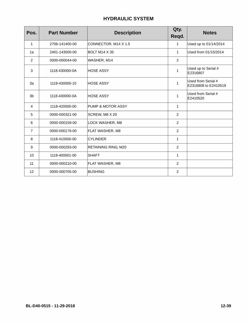
HYDRAULIC SYSTEM
Pos. Part Number DescriptionQty.
Reqd.Notes
1 2706-141400-00 CONNECTOR, M14 X 1.5 1 Used up to 01/14/2014
1a 2401-143500-00 BOLT M14 X 35 1 Used from 01/15/2014
2 0000-000044-00 WASHER, M14 2
3 1118-430000-0A HOSE ASSY 1Used up to Serial # E2316807
3a 1118-430000-10 HOSE ASSY 1Used from Serial # E2316808 to E2410519
3b 1118-430000-0A HOSE ASSY 1Used from Serial # E2410520
4 1118-420000-00 PUMP & MOTOR ASSY 1
5 0000-000321-00 SCREW, M8 X 20 2
6 0000-000159-00 LOCK WASHER, M8 2
7 0000-000176-00 FLAT WASHER, M8 2
8 1118-410000-00 CYLINDER 1
9 0000-000293-00 RETAINING RING, M20 2
10 1118-400001-00 SHAFT 1
11 0000-000210-00 FLAT WASHER, M8 2
12 0000-000705-00 BUSHING 2
BL-D40-0515 - 11-29-2018 12-39

Figure 12-19 Pump & Motor Assy
DK_0015
12-40 BL-D40-0515 - 11-29-2018
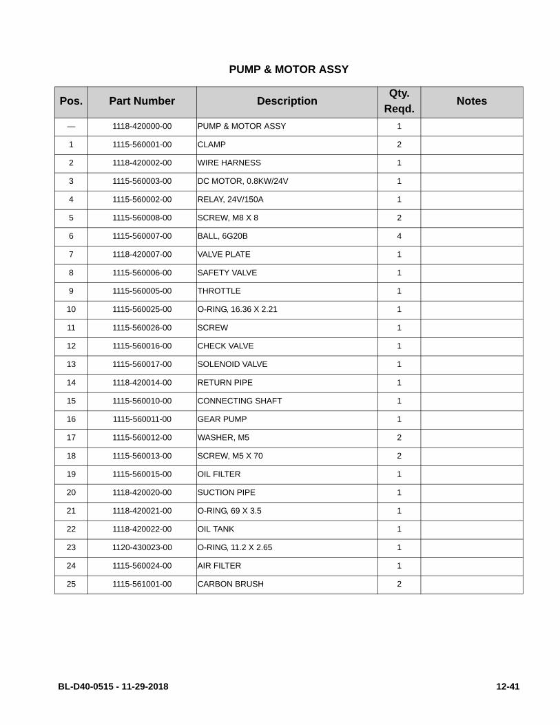
PUMP & MOTOR ASSY
Pos. Part Number DescriptionQty.
Reqd.Notes
— 1118-420000-00 PUMP & MOTOR ASSY 1
1 1115-560001-00 CLAMP 2
2 1118-420002-00 WIRE HARNESS 1
3 1115-560003-00 DC MOTOR, 0.8KW/24V 1
4 1115-560002-00 RELAY, 24V/150A 1
5 1115-560008-00 SCREW, M8 X 8 2
6 1115-560007-00 BALL, 6G20B 4
7 1118-420007-00 VALVE PLATE 1
8 1115-560006-00 SAFETY VALVE 1
9 1115-560005-00 THROTTLE 1
10 1115-560025-00 O-RING, 16.36 X 2.21 1
11 1115-560026-00 SCREW 1
12 1115-560016-00 CHECK VALVE 1
13 1115-560017-00 SOLENOID VALVE 1
14 1118-420014-00 RETURN PIPE 1
15 1115-560010-00 CONNECTING SHAFT 1
16 1115-560011-00 GEAR PUMP 1
17 1115-560012-00 WASHER, M5 2
18 1115-560013-00 SCREW, M5 X 70 2
19 1115-560015-00 OIL FILTER 1
20 1118-420020-00 SUCTION PIPE 1
21 1118-420021-00 O-RING, 69 X 3.5 1
22 1118-420022-00 OIL TANK 1
23 1120-430023-00 O-RING, 11.2 X 2.65 1
24 1115-560024-00 AIR FILTER 1
25 1115-561001-00 CARBON BRUSH 2
BL-D40-0515 - 11-29-2018 12-41

Figure 12-20 Lift Cylinder
DK_0016
12-42 BL-D40-0515 - 11-29-2018
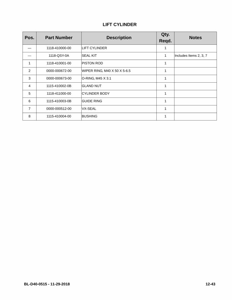
LIFT CYLINDER
Pos. Part Number DescriptionQty.
Reqd.Notes
— 1118-410000-00 LIFT CYLINDER 1
— 1118-QSY-0A SEAL KIT 1 Includes Items 2, 3, 7
1 1118-410001-00 PISTON ROD 1
2 0000-000672-00 WIPER RING, M40 X 50 X 5-6.5 1
3 0000-000673-00 O-RING, M45 X 3.1 1
4 1115-410002-0B GLAND NUT 1
5 1118-411000-00 CYLINDER BODY 1
6 1115-410003-0B GUIDE RING 1
7 0000-000512-00 VX-SEAL 1
8 1115-410004-00 BUSHING 1
BL-D40-0515 - 11-29-2018 12-43

Figure 12-21 Electrical System
DK_0017
12-44 BL-D40-0515 - 11-29-2018

P
ELECTRICAL SYSTEM
os. Part Number DescriptionQty.
Reqd.Notes
1 0000-000030-00 SCREW, M10 X 16 4
2 0000-000063-00 LOCK WASHER, M10 4
3 0000-000007-00 FLAT WASHER, M10 4
4 1118-511000-00 ELECTRICAL MOUNTING PLATE 1 Up to Serial # E2410289
4a 1118-511000-70 ELECTRICAL MOUNTING PLATE 1 From Serial # E2410290
5 0000-000368-00 SCREW, M8 X 12 2
6 2214-150002-00 WASHER 2
7 0000-000108-00 NUT, M6 4 Used up to 04/23/2014
8 1118-540000-00 BOARD 1 Up to Serial # 324170264
8a 1118-540000-70 BOARD 1 From Serial # 324170265
9 0000-000117-00 SCREW, M5 X 10 3
10 0000-000206-00 LOCK WASHER, M5 5
11 0000-000390-00 FLAT WASHER, M5 5
12 0000-001103-00 R HARNESS CLAMP UC-1.5 2
13 0000-001086-00 R HARNESS CLAMP UC-5 2
14 2112-410005-00 RUBBER CUSHION 2 Used up to 10/27/2013
14a 1115-100005-00 RUBBER CUSHION 2 Used from 10/28/2013
15 1118-500002-00 BRACKET 1
16 0000-000004-00 SCREW, M5 X 12 2
17 1120-500006-00 LIFTING LIMIT SWITCH 1
18 1118-520007-10 WIRE HARNESS OF LIMIT SWITCH 1
19 0000-001031-00 SCREW, M4 X 30 2
20 0000-000122-00 LOCK WASHER, M4 2
21 0000-000139-00 NUT, M4 2
22 003231 BATTERY 2 85Ah Battery
22a 1118-560007-00 BATTERY 2 100Ah Battery
23 1118-100011-00 SPACER A.R. As required
24 1118-100010-00 PLATE 2 Used up to 04/23/2014
25 0000-000055-00 SCREW, M6 X 16 4 Used up to 04/23/2014
26 1115-100002-00 SPACER A.R. As required
27 1280-100005-00 FLAT PLUG 1 Up to Serial # 324170264
BL-D40-0515 - 11-29-2018 12-45

Figure 12-22 Drive Motor Assembly
DK_0018
12-46 BL-D40-0515 - 11-29-2018

DRIVE MOTOR ASSEMBLY
Pos. Part Number DescriptionQty.
Reqd.Notes
-- 1120-220000-00 MOTOR ASSEMBLY 1
1 0000-000293-00 RETAINING RING, M20 2
2 0000-000226-00 KEY 1
3 1120-220001-00 TERMINAL BLOCK 1
4 0000-000206-00 LOCK WASHER, M5 17
5 0000-000117-00 SCREW, M5 X 10 2
6 0000-000166-00 NUT, M6 6
7 0000-000056-00 LOCK WASHER, M6 6
8 1120-220002-00 BEARING 1
9 0000-000204-00 KEY 1
10 0000-000409-00 O-RING, M63 X 3.55 1
11 0000-000436-00 NUT, M12 X 1.5 1
12 0000-000323-00 SCREW, M5 X 16 14
BL-D40-0515 - 11-29-2018 12-47

Figure 12-23 Electrical Components (Sheet 1)
DK_0019
12-48 BL-D40-0515 - 11-29-2018
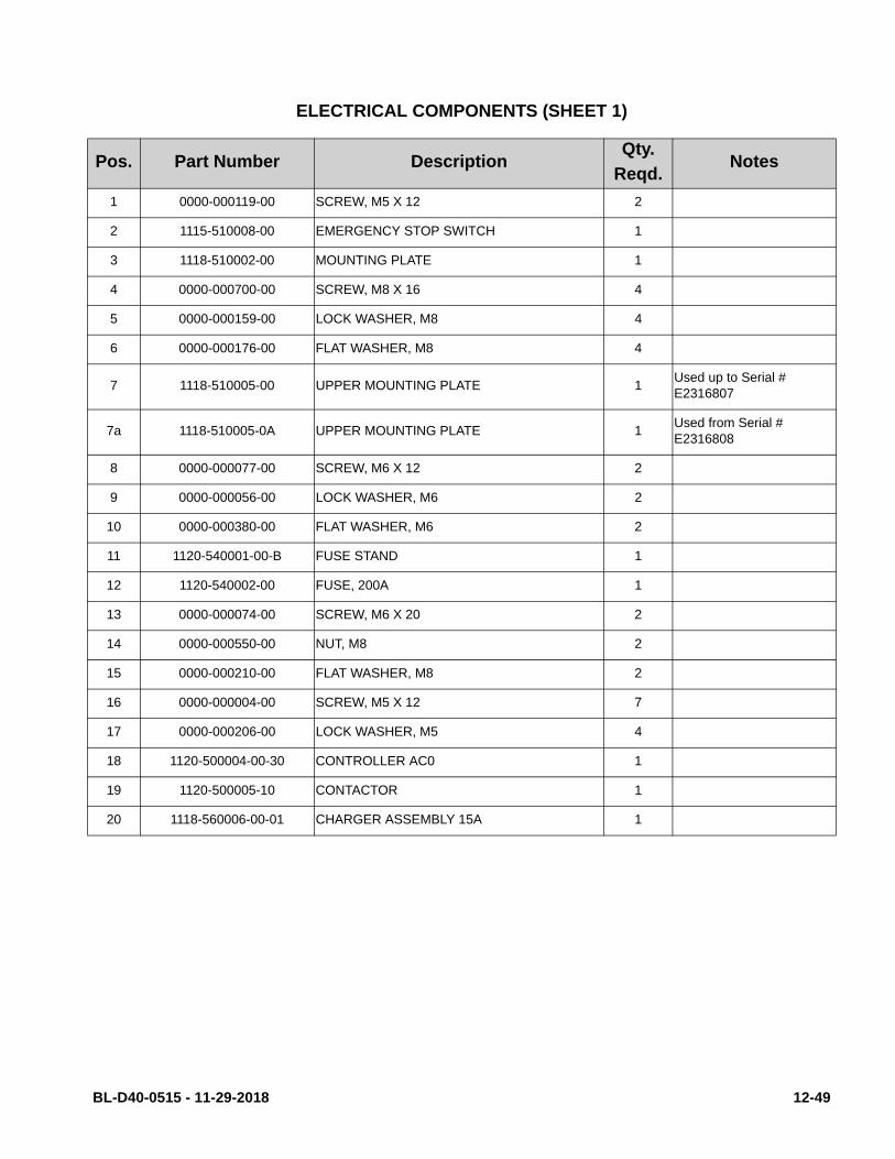
ELECTRICAL COMPONENTS (SHEET 1)
Pos. Part Number DescriptionQty.
Reqd.Notes
1 0000-000119-00 SCREW, M5 X 12 2
2 1115-510008-00 EMERGENCY STOP SWITCH 1
3 1118-510002-00 MOUNTING PLATE 1
4 0000-000700-00 SCREW, M8 X 16 4
5 0000-000159-00 LOCK WASHER, M8 4
6 0000-000176-00 FLAT WASHER, M8 4
7 1118-510005-00 UPPER MOUNTING PLATE 1Used up to Serial # E2316807
7a 1118-510005-0A UPPER MOUNTING PLATE 1Used from Serial # E2316808
8 0000-000077-00 SCREW, M6 X 12 2
9 0000-000056-00 LOCK WASHER, M6 2
10 0000-000380-00 FLAT WASHER, M6 2
11 1120-540001-00-B FUSE STAND 1
12 1120-540002-00 FUSE, 200A 1
13 0000-000074-00 SCREW, M6 X 20 2
14 0000-000550-00 NUT, M8 2
15 0000-000210-00 FLAT WASHER, M8 2
16 0000-000004-00 SCREW, M5 X 12 7
17 0000-000206-00 LOCK WASHER, M5 4
18 1120-500004-00-30 CONTROLLER AC0 1
19 1120-500005-10 CONTACTOR 1
20 1118-560006-00-01 CHARGER ASSEMBLY 15A 1
BL-D40-0515 - 11-29-2018 12-49

Figure 12-23Electrical Components (Sheet 1) - Continued
DK_0019
12-50 BL-D40-0515 - 11-29-2018
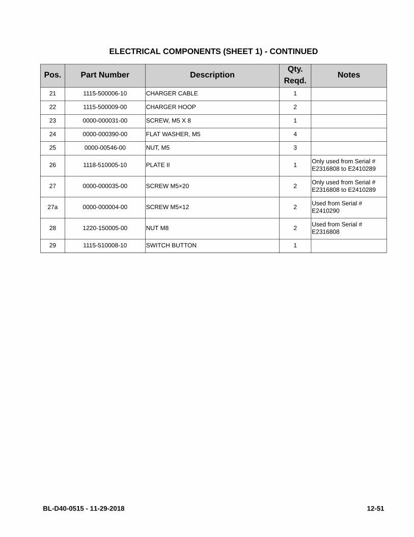
ELECTRICAL COMPONENTS (SHEET 1) - CONTINUED
Pos. Part Number DescriptionQty.
Reqd.Notes
21 1115-500006-10 CHARGER CABLE 1
22 1115-500009-00 CHARGER HOOP 2
23 0000-000031-00 SCREW, M5 X 8 1
24 0000-000390-00 FLAT WASHER, M5 4
25 0000-00546-00 NUT, M5 3
26 1118-510005-10 PLATE II 1Only used from Serial # E2316808 to E2410289
27 0000-000035-00 SCREW M5×20 2Only used from Serial # E2316808 to E2410289
27a 0000-000004-00 SCREW M5×12 2Used from Serial # E2410290
28 1220-150005-00 NUT M8 2Used from Serial # E2316808
29 1115-510008-10 SWITCH BUTTON 1
BL-D40-0515 - 11-29-2018 12-51

Figure 12-24 Electrical Components (Sheet 2)
DK_0020
12-52 BL-D40-0515 - 11-29-2018

ELECTRICAL COMPONENTS (SHEET 2)
Part Number DescriptionQty.
Reqd.Notes
1 1118-560001-00 TIMING RELAY 1
Optional up to serial number 324170264. Standard from serial number 324170265
2 1118-560002-00 TIMING RELAY SET 1
3 1118-510001-00 RELAY BRACKET 1
4 0000-000009-00 SCREW, M4 X 12 2
5 000-000031-00 SCREW, M5 X 8 4
6 0000-000206-00 LOCK WASHER, M5 6
7 0000-000390-00 FLAT WASHER, M5 6
8 1118-520006-10 RELAY WIRE HARNESS 1 See note for pos. 1-4
9 1118-510004-00 TIE PLATE 1
10 0000-000004-00 SCREW, M5 X 12 2
11 1118-510003-00 PLATE 1
12 1115-520015-00 BUZZER ASSEMBLY 1
13 0000-000037-00 SCREW, M3 X 12 2
14 0000-000139-00 NUT, M4 2
15 1115-520007-00 FAN ASSEMBLY 1
16 1115-500007-00 FAN GUARD 1
17 0000-000121-00 SCREW, M4 X 35 4
18 0000-000122-00 LOCK WASHER, M4 4
19 0000-000702-00 FLAT WASHER, M4 4
20 1115-520019-0A 2-WAY SWITCH 1
21 1115-500016-00 2-WAY SWITCH KEY 2
22 1115-520013-00 LED WIRE HARNESS 1
23 1115-510009-00 LAMP HOLDER 1
BL-D40-0515 - 11-29-2018 12-53

Figure 12-24 Electrical Components (Sheet 2) - Continued
DK_0020
12-54 BL-D40-0515 - 11-29-2018

ELECTRICAL COMPONENTS (SHEET 2) - CONTINUED
Part Number DescriptionQty.
Reqd.Notes
24 1118-522000-00 BRAKE RELEASE BUTTON 1
Optional up to serial num-ber 324170264. Standard from serial number 324170265
25 1115-520005-0A BDI WIRE HARNESS 1 Without Hourmeter
25a 1115-520005-20 BDI WIRE HARNESS 1 With Hourmeter
26 0000-000498-00 SCREW M6 X 30 2Used from serial number 324170265
27 1118-540002-70 PLATE 1Used from serial number 324170265
28 1115-510006-00 BDI (BATTERY INDICATOR) 1
Without Hourmeter. Set the BDI dial to the follow-ing: M = Industrial Battery, Q = Maint.Free Battery
28a 1115-510006-20 BDI (BATTERY INDICATOR) 1
With Hourmeter. Set the BDI dial to the following: M = Industrial Battery, Q = Maint.Free Battery
29 1118-510004-10 PLATE I 1Only used from Serial # E2316808 to E2410289
30 0000-000108-00 NUT M6 4Used from serial number 324170265
BL-D40-0515 - 11-29-2018 12-55

Figure 12-24 Electrical Components - Freezer
DK_0030
12-56 BL-D40-0515 - 11-29-2018
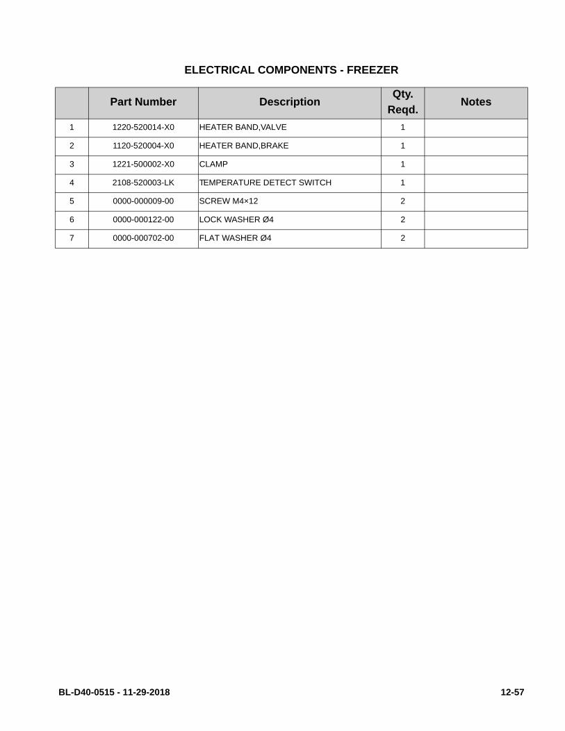
ELECTRICAL COMPONENTS - FREEZER
Part Number DescriptionQty.
Reqd.Notes
1 1220-520014-X0 HEATER BAND,VALVE 1
2 1120-520004-X0 HEATER BAND,BRAKE 1
3 1221-500002-X0 CLAMP 1
4 2108-520003-LK TEMPERATURE DETECT SWITCH 1
5 0000-000009-00 SCREW M4×12 2
6 0000-000122-00 LOCK WASHER Ø4 2
7 0000-000702-00 FLAT WASHER Ø4 2
BL-D40-0515 - 11-29-2018 12-57

Figure 12-25 Wiring Harness
DK_0021
12-58 BL-D40-0515 - 11-29-2018

WIRING HARNESS
Pos. Part Number DescriptionQty.
Reqd.Notes
1 1118-520001-00 MASTER WIRE HARNESS 1
2 1120-500010-00 FUSE 10A 1
3 1118-520002-00 SWITCHING WIRE HARNESS 1
4 1118-520004-00 WIRE HARNESS OF PUMP 1
5 1118-520008-10 SHORT CIRCUIT SWITCH 1Only used up to serial num-ber 324170264 (Optional)
BL-D40-0515 - 11-29-2018 12-59
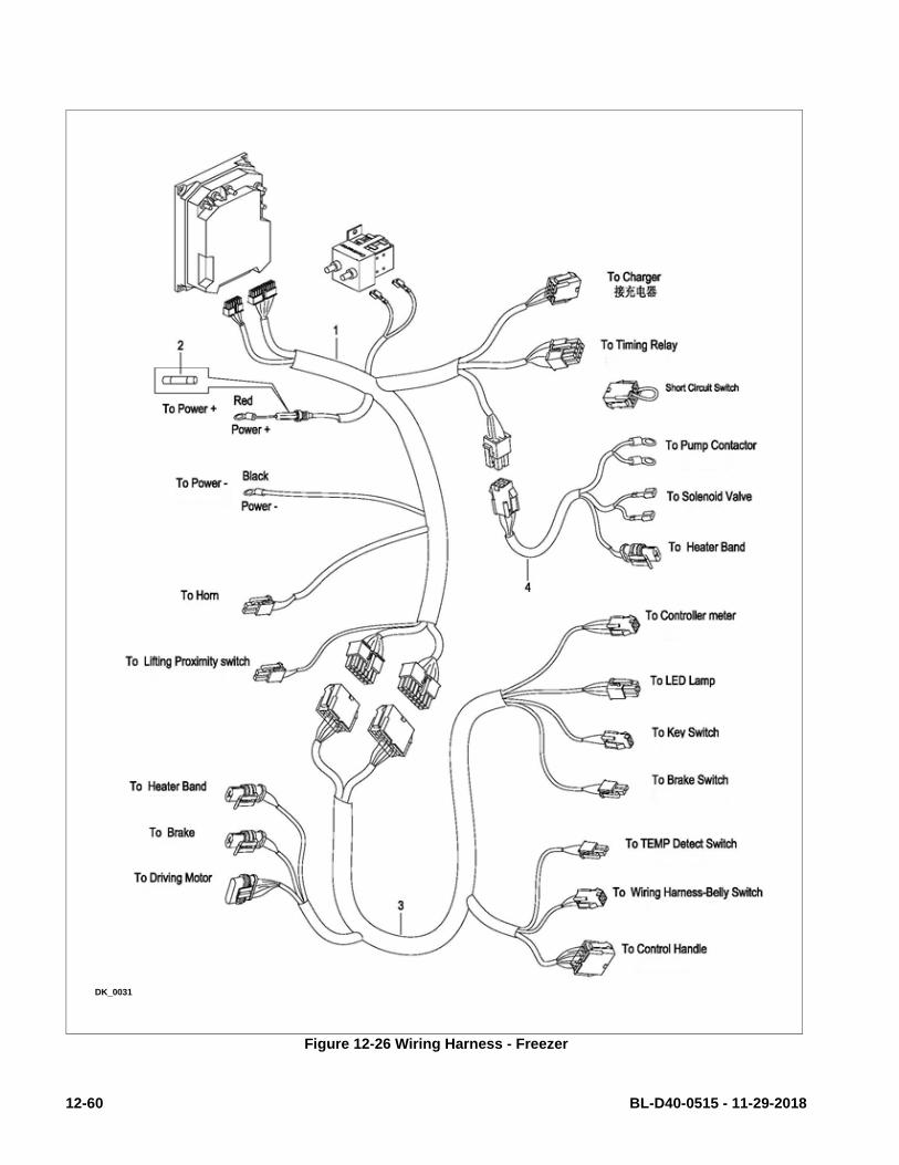
Figure 12-26 Wiring Harness - Freezer
DK_0031
12-60 BL-D40-0515 - 11-29-2018

WIRING HARNESS - FREEZER
Pos. Part Number DescriptionQty.
Reqd.Notes
1 1118-520001-X0 MASTER WIRE HARNESS 1
2 1120-500010-00 FUSE 10A 1
3 1118-520002-X0 SWITCHING WIRE HARNESS 1
4 1118-520004-X0 WIRE HARNESS OF PUMP 1
BL-D40-0515 - 11-29-2018 12-61

Figure 12-27 Wiring Cables
DK_0022
12-62 BL-D40-0515 - 11-29-2018
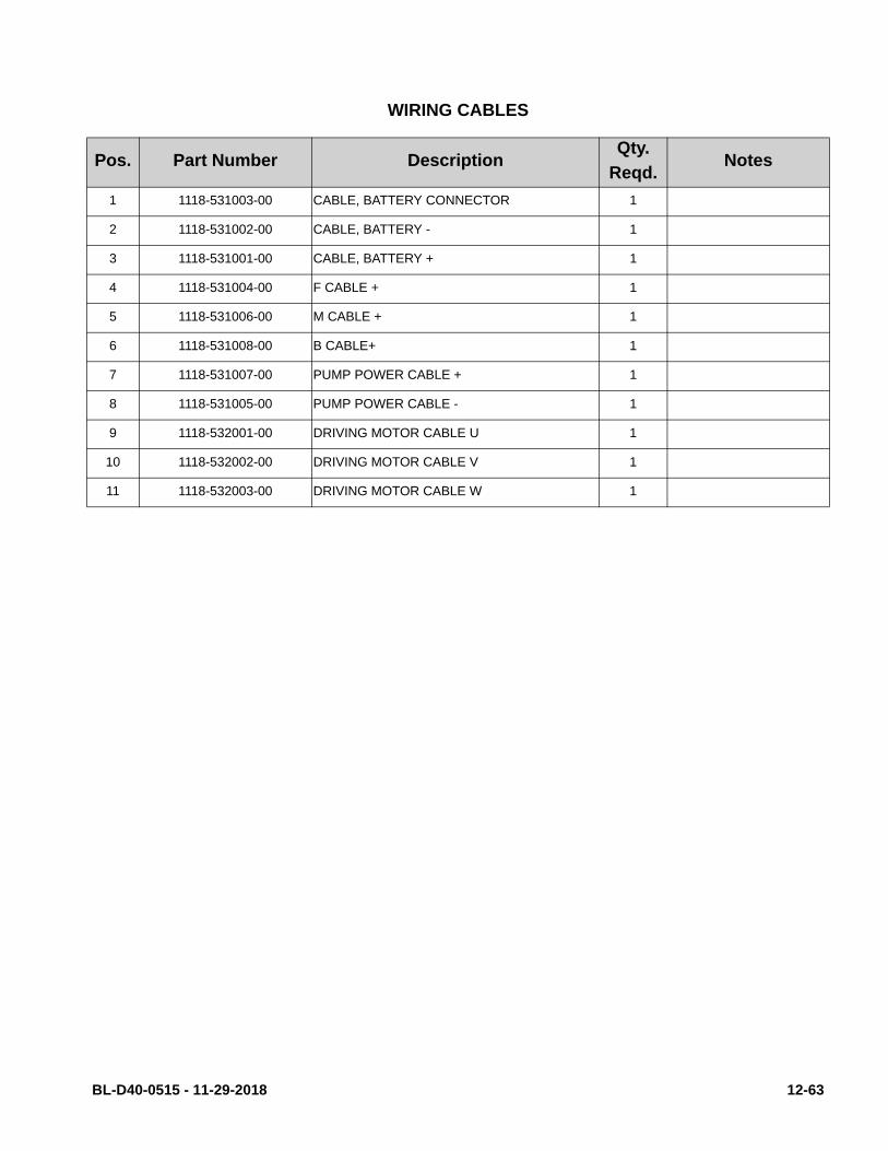
WIRING CABLES
Pos. Part Number DescriptionQty.
Reqd.Notes
1 1118-531003-00 CABLE, BATTERY CONNECTOR 1
2 1118-531002-00 CABLE, BATTERY - 1
3 1118-531001-00 CABLE, BATTERY + 1
4 1118-531004-00 F CABLE + 1
5 1118-531006-00 M CABLE + 1
6 1118-531008-00 B CABLE+ 1
7 1118-531007-00 PUMP POWER CABLE + 1
8 1118-531005-00 PUMP POWER CABLE - 1
9 1118-532001-00 DRIVING MOTOR CABLE U 1
10 1118-532002-00 DRIVING MOTOR CABLE V 1
11 1118-532003-00 DRIVING MOTOR CABLE W 1
BL-D40-0515 - 11-29-2018 12-63

Big Lift LLC